EP3760114B1 - Subcutaneous implantable medical device for processing signals from a subcutaneous implantable medical device - Google Patents
Subcutaneous implantable medical device for processing signals from a subcutaneous implantable medical device Download PDFInfo
- Publication number
- EP3760114B1 EP3760114B1 EP20183499.1A EP20183499A EP3760114B1 EP 3760114 B1 EP3760114 B1 EP 3760114B1 EP 20183499 A EP20183499 A EP 20183499A EP 3760114 B1 EP3760114 B1 EP 3760114B1
- Authority
- EP
- European Patent Office
- Prior art keywords
- dipole
- signals
- subcutaneous implantable
- medical device
- subcutaneous
- Prior art date
- Legal status (The legal status is an assumption and is not a legal conclusion. Google has not performed a legal analysis and makes no representation as to the accuracy of the status listed.)
- Active
Links
- 238000007920 subcutaneous administration Methods 0.000 title claims description 71
- 238000001514 detection method Methods 0.000 claims description 68
- 208000001871 Tachycardia Diseases 0.000 claims description 54
- 206010049447 Tachyarrhythmia Diseases 0.000 claims description 53
- 230000000747 cardiac effect Effects 0.000 claims description 27
- 239000013598 vector Substances 0.000 claims description 20
- 230000033764 rhythmic process Effects 0.000 claims description 19
- 230000000694 effects Effects 0.000 claims description 7
- 238000000718 qrs complex Methods 0.000 claims description 7
- 230000028161 membrane depolarization Effects 0.000 claims description 6
- 230000008859 change Effects 0.000 claims description 4
- 238000000034 method Methods 0.000 description 36
- 239000000523 sample Substances 0.000 description 33
- 238000004458 analytical method Methods 0.000 description 12
- 238000004422 calculation algorithm Methods 0.000 description 12
- 230000006870 function Effects 0.000 description 10
- 238000003672 processing method Methods 0.000 description 10
- 238000004364 calculation method Methods 0.000 description 9
- 206010047302 ventricular tachycardia Diseases 0.000 description 5
- 230000002169 extracardiac Effects 0.000 description 3
- 230000003387 muscular Effects 0.000 description 3
- 230000008569 process Effects 0.000 description 3
- 210000003462 vein Anatomy 0.000 description 3
- 208000003663 ventricular fibrillation Diseases 0.000 description 3
- 208000003734 Supraventricular Tachycardia Diseases 0.000 description 2
- 238000012790 confirmation Methods 0.000 description 2
- 208000015181 infectious disease Diseases 0.000 description 2
- 210000004072 lung Anatomy 0.000 description 2
- 230000036279 refractory period Effects 0.000 description 2
- 230000035939 shock Effects 0.000 description 2
- 230000009885 systemic effect Effects 0.000 description 2
- 230000000472 traumatic effect Effects 0.000 description 2
- 206010065341 Ventricular tachyarrhythmia Diseases 0.000 description 1
- 230000004075 alteration Effects 0.000 description 1
- 239000003242 anti bacterial agent Substances 0.000 description 1
- 229940088710 antibiotic agent Drugs 0.000 description 1
- 206010003119 arrhythmia Diseases 0.000 description 1
- 230000006793 arrhythmia Effects 0.000 description 1
- 239000008280 blood Substances 0.000 description 1
- 210000004369 blood Anatomy 0.000 description 1
- 210000005242 cardiac chamber Anatomy 0.000 description 1
- 238000004141 dimensional analysis Methods 0.000 description 1
- 238000000605 extraction Methods 0.000 description 1
- 238000013213 extrapolation Methods 0.000 description 1
- 238000001914 filtration Methods 0.000 description 1
- 230000001771 impaired effect Effects 0.000 description 1
- 238000002513 implantation Methods 0.000 description 1
- 230000007257 malfunction Effects 0.000 description 1
- 238000005259 measurement Methods 0.000 description 1
- 239000002184 metal Substances 0.000 description 1
- 230000000877 morphologic effect Effects 0.000 description 1
- 210000003205 muscle Anatomy 0.000 description 1
- 210000004165 myocardium Anatomy 0.000 description 1
- 238000010606 normalization Methods 0.000 description 1
- 238000007781 pre-processing Methods 0.000 description 1
- 238000005070 sampling Methods 0.000 description 1
- 230000035945 sensitivity Effects 0.000 description 1
- 210000001321 subclavian vein Anatomy 0.000 description 1
- 230000006794 tachycardia Effects 0.000 description 1
- 230000003442 weekly effect Effects 0.000 description 1
Images


Classifications
-
- A—HUMAN NECESSITIES
- A61—MEDICAL OR VETERINARY SCIENCE; HYGIENE
- A61N—ELECTROTHERAPY; MAGNETOTHERAPY; RADIATION THERAPY; ULTRASOUND THERAPY
- A61N1/00—Electrotherapy; Circuits therefor
- A61N1/18—Applying electric currents by contact electrodes
- A61N1/32—Applying electric currents by contact electrodes alternating or intermittent currents
- A61N1/38—Applying electric currents by contact electrodes alternating or intermittent currents for producing shock effects
- A61N1/39—Heart defibrillators
- A61N1/3956—Implantable devices for applying electric shocks to the heart, e.g. for cardioversion
-
- A—HUMAN NECESSITIES
- A61—MEDICAL OR VETERINARY SCIENCE; HYGIENE
- A61B—DIAGNOSIS; SURGERY; IDENTIFICATION
- A61B5/00—Measuring for diagnostic purposes; Identification of persons
- A61B5/72—Signal processing specially adapted for physiological signals or for diagnostic purposes
- A61B5/7221—Determining signal validity, reliability or quality
-
- A—HUMAN NECESSITIES
- A61—MEDICAL OR VETERINARY SCIENCE; HYGIENE
- A61N—ELECTROTHERAPY; MAGNETOTHERAPY; RADIATION THERAPY; ULTRASOUND THERAPY
- A61N1/00—Electrotherapy; Circuits therefor
- A61N1/18—Applying electric currents by contact electrodes
- A61N1/32—Applying electric currents by contact electrodes alternating or intermittent currents
- A61N1/38—Applying electric currents by contact electrodes alternating or intermittent currents for producing shock effects
- A61N1/39—Heart defibrillators
- A61N1/3925—Monitoring; Protecting
-
- A—HUMAN NECESSITIES
- A61—MEDICAL OR VETERINARY SCIENCE; HYGIENE
- A61B—DIAGNOSIS; SURGERY; IDENTIFICATION
- A61B5/00—Measuring for diagnostic purposes; Identification of persons
- A61B5/24—Detecting, measuring or recording bioelectric or biomagnetic signals of the body or parts thereof
- A61B5/25—Bioelectric electrodes therefor
- A61B5/279—Bioelectric electrodes therefor specially adapted for particular uses
- A61B5/28—Bioelectric electrodes therefor specially adapted for particular uses for electrocardiography [ECG]
- A61B5/283—Invasive
-
- A—HUMAN NECESSITIES
- A61—MEDICAL OR VETERINARY SCIENCE; HYGIENE
- A61B—DIAGNOSIS; SURGERY; IDENTIFICATION
- A61B5/00—Measuring for diagnostic purposes; Identification of persons
- A61B5/24—Detecting, measuring or recording bioelectric or biomagnetic signals of the body or parts thereof
- A61B5/30—Input circuits therefor
-
- A—HUMAN NECESSITIES
- A61—MEDICAL OR VETERINARY SCIENCE; HYGIENE
- A61B—DIAGNOSIS; SURGERY; IDENTIFICATION
- A61B5/00—Measuring for diagnostic purposes; Identification of persons
- A61B5/24—Detecting, measuring or recording bioelectric or biomagnetic signals of the body or parts thereof
- A61B5/316—Modalities, i.e. specific diagnostic methods
- A61B5/318—Heart-related electrical modalities, e.g. electrocardiography [ECG]
- A61B5/346—Analysis of electrocardiograms
- A61B5/349—Detecting specific parameters of the electrocardiograph cycle
- A61B5/352—Detecting R peaks, e.g. for synchronising diagnostic apparatus; Estimating R-R interval
-
- A—HUMAN NECESSITIES
- A61—MEDICAL OR VETERINARY SCIENCE; HYGIENE
- A61B—DIAGNOSIS; SURGERY; IDENTIFICATION
- A61B5/00—Measuring for diagnostic purposes; Identification of persons
- A61B5/24—Detecting, measuring or recording bioelectric or biomagnetic signals of the body or parts thereof
- A61B5/316—Modalities, i.e. specific diagnostic methods
- A61B5/318—Heart-related electrical modalities, e.g. electrocardiography [ECG]
- A61B5/346—Analysis of electrocardiograms
- A61B5/349—Detecting specific parameters of the electrocardiograph cycle
- A61B5/363—Detecting tachycardia or bradycardia
-
- A—HUMAN NECESSITIES
- A61—MEDICAL OR VETERINARY SCIENCE; HYGIENE
- A61B—DIAGNOSIS; SURGERY; IDENTIFICATION
- A61B5/00—Measuring for diagnostic purposes; Identification of persons
- A61B5/72—Signal processing specially adapted for physiological signals or for diagnostic purposes
- A61B5/7271—Specific aspects of physiological measurement analysis
- A61B5/7282—Event detection, e.g. detecting unique waveforms indicative of a medical condition
-
- A—HUMAN NECESSITIES
- A61—MEDICAL OR VETERINARY SCIENCE; HYGIENE
- A61N—ELECTROTHERAPY; MAGNETOTHERAPY; RADIATION THERAPY; ULTRASOUND THERAPY
- A61N1/00—Electrotherapy; Circuits therefor
- A61N1/02—Details
- A61N1/04—Electrodes
- A61N1/05—Electrodes for implantation or insertion into the body, e.g. heart electrode
- A61N1/0504—Subcutaneous electrodes
-
- A—HUMAN NECESSITIES
- A61—MEDICAL OR VETERINARY SCIENCE; HYGIENE
- A61N—ELECTROTHERAPY; MAGNETOTHERAPY; RADIATION THERAPY; ULTRASOUND THERAPY
- A61N1/00—Electrotherapy; Circuits therefor
- A61N1/18—Applying electric currents by contact electrodes
- A61N1/32—Applying electric currents by contact electrodes alternating or intermittent currents
- A61N1/38—Applying electric currents by contact electrodes alternating or intermittent currents for producing shock effects
- A61N1/39—Heart defibrillators
- A61N1/3925—Monitoring; Protecting
- A61N1/3937—Monitoring output parameters
- A61N1/3943—Monitoring output parameters for threshold determination
-
- A—HUMAN NECESSITIES
- A61—MEDICAL OR VETERINARY SCIENCE; HYGIENE
- A61N—ELECTROTHERAPY; MAGNETOTHERAPY; RADIATION THERAPY; ULTRASOUND THERAPY
- A61N1/00—Electrotherapy; Circuits therefor
- A61N1/18—Applying electric currents by contact electrodes
- A61N1/32—Applying electric currents by contact electrodes alternating or intermittent currents
- A61N1/38—Applying electric currents by contact electrodes alternating or intermittent currents for producing shock effects
- A61N1/39—Heart defibrillators
- A61N1/395—Heart defibrillators for treating atrial fibrillation
-
- A—HUMAN NECESSITIES
- A61—MEDICAL OR VETERINARY SCIENCE; HYGIENE
- A61N—ELECTROTHERAPY; MAGNETOTHERAPY; RADIATION THERAPY; ULTRASOUND THERAPY
- A61N1/00—Electrotherapy; Circuits therefor
- A61N1/18—Applying electric currents by contact electrodes
- A61N1/32—Applying electric currents by contact electrodes alternating or intermittent currents
- A61N1/38—Applying electric currents by contact electrodes alternating or intermittent currents for producing shock effects
- A61N1/39—Heart defibrillators
- A61N1/3968—Constructional arrangements, e.g. casings
Definitions
- the present invention relates to a subcutaneous implantable cardiac device, in particular a subcutaneous implantable defibrillator as described in claim 1.
- Conventional implantable automatic defibrillators that is to say of the transvenous type, also abbreviated ICD for “Implantable Cardioverter-Defibrillator” in English, include a defibrillation pulse generator and a microprocessor control unit housed in a metal housing usually implanted subcutaneously in the pectoral pocket. This box is connected to one or more probes which are introduced into the subclavian vein where they ultimately reach the heart. Inside the heart, the distal ends of the leads are attached to the inner walls of the heart chambers, where they can record electrograms (EGMs) reflecting the electrophysiological functioning of the heart.
- EGMs electrograms
- treatment in the form of defibrillation is administered (or interrupted) in order to terminate a life-threatening ventricular tachyarrhythmia, such as ventricular tachycardia and ventricular fibrillation.
- the weakest elements of these transvenous implantable cardioverter defibrillators are the intracardiac leads.
- Lead fracture is one of the most common causes of pacemaker malfunction. Removal of an implanted ICD lead (or pacemaker) is a procedure with high morbidity and mortality, and is therefore usually only performed in cases of serious systemic infection that cannot be treated with antibiotics. In the majority of cases, the fractured leads will be disconnected from the device and left in the heart. A new lead is then implanted next to the old one and connected to the implantable cardioverter defibrillator.
- this solution is only possible if there is still enough space in the vein, as the presence of more probes can lead to vein occlusion. Therefore, the use of intracardiac leads is not ideally suited to young patients, who may require a multitude of leads during their lifetime.
- Subcutaneous implantable devices record subcutaneous electrocardiograms (ECGs) – rather than EGMs – that capture spatially averaged far-field electrophysiological activity. P waves and T waves are then more prominent in subcutaneous signals compared to R waves, making it more difficult to detect the RR interval on which many tachyarrhythmia detection algorithms are based.
- ECGs subcutaneous electrocardiograms
- Non-cardiac noise sources such as myopotentials, can also alter subcutaneous signals and interfere with detection algorithms, disrupting treatment. Additionally, subcutaneous signals tend to be more sensitive to changes in posture than intracardiac signals.
- Algorithms or methods for processing endocavitary electrogram signals are configured to make it possible to discriminate a true ventricular tachycardia (VT) from a supraventricular tachycardia (SVT).
- VT true ventricular tachycardia
- SVT supraventricular tachycardia
- these known algorithms are not suitable for detecting tachyarrhythmia from signals collected subcutaneously.
- subcutaneous defibrillators are more likely to be subject to overdetection of noise and P, T waves; it is necessary, in the particular case of subcutaneous defibrillators, to minimize the risk of diagnosing VT or ventricular fibrillation (VF) when there is overdetection of noise or P, T waves. Erroneous interpretation of the signals collected could lead, for example in an implantable automatic defibrillator, to an inappropriate shock, which could be traumatic or even harmful for the patient.
- VF ventricular fibrillation
- US 8,577,455 B2 discloses a device for detecting arrhythmias in a patient, including subcutaneous electrodes and a processor capable of processing cardiac signals.
- US 2005/049644 A1 discloses an implantable cardiac treatment system, capable of selecting the most appropriate electrode vector for continuous detection and improving the detection of cardiac events.
- the object of the present invention is therefore to improve the processing of signals collected by means of a subcutaneous probe of a subcutaneous medical device, in particular to improve the sensitivity and specificity of the detection and discrimination of tachyarrhythmia episodes recorded from a subcutaneous probe.
- an active subcutaneous implantable medical device in particular a subcutaneous cardiac defibrillator, comprising: a housing, a subcutaneous implantable probe connected to the housing, the subcutaneous implantable probe comprising a plurality of detection electrodes forming at least two dipoles from which at least two electrical signals are concurrently collected; the first dipole having a length less than that of the second dipole; the device further comprising a controller configured to determine the presence or absence of a tachyarrhythmia by determining a similarity criterion from the electrical signals collected concurrently via the first dipole and via the second dipole during a defined series of cardiac cycles, such as the detection of a depolarization peak, corresponding to the detection of an R wave, is carried out via the first dipole.
- the detection of a depolarization peak from the signals collected via the first dipole makes it possible to improve the quality of detection of the R wave subcutaneously because the first dipole is the shorter of the two dipoles of the probe subcutaneous, and is therefore less exposed to the risk of overdetection of noise or error when detecting the QRS complex compared to the second dipole.
- the distance covered between the electrodes of the first dipole is reduced, which reduces the risk of signal alteration by an external source. There is, for example, less muscle mass between the electrodes that can introduce myopotentials.
- the present invention relating to an active medical device implantable under the skin, can be further improved thanks to the following embodiments.
- the signals collected via the first dipole and the second dipole of the subcutaneous implantable probe can be considered over a time window comprising a QRS complex and centered on the detection of the R wave, the detection of the R wave being only carried out via the first dipole.
- the RR interval of the signals collected via the first dipole can be determined and a time window, for example from 80 to 150 milliseconds, in particular 100 milliseconds, can be centered on the detection of the R wave carried out via the first dipole.
- the detection of the R wave is thus not carried out on the second dipole so as not to add further calculation cost.
- the signals from the second dipole collected concurrently with those from the first dipole, in particular only during a time window, can be recorded in the memory of the device.
- the controller is configured to combine the signals collected via the first dipole and the signals collected via the second dipole, and from the representation of the signals collected via the second dipole as a function of the signals collected via the first dipole, to determine a two-dimensional curve parameterized as a function of time representative of the cardiac activity of a patient, the similarity criterion being defined by the comparison, in particular a correlation, between said two-dimensional curve and a two-dimensional reference curve representative in sinus rhythm normal.
- the determination of the two-dimensional curve by the controller makes it possible to combine signals collected according to the first dipole with those collected according to the second dipole: it is thus made possible to simultaneously take into account the information coming from the two dipoles of the subcutaneous probe, in particular by considering - depending on the dipole - different morphologies of electrical signals, which contributes to obtaining more relevant parameters relating to the origin of the signal collected. These parameters relating to the origin of the signal collected participate in particular in determining the similarity criterion.
- the controller can further be configured to identify the presence or absence of unwanted noise in the signals collected as a function of the change in sign of at least one of the coordinates of a tangent vector between each successive point of a plurality of points of said two-dimensional curve. More specifically, the controller can be configured to identify the presence of unwanted noise by determining the number of times that at least one of the coordinates of the tangent vector changes sign between each successive point of the plurality of points of said two-dimensional curve and comparing this number has a predetermined threshold number indicating unwanted noise.
- the two-dimensional curve can be represented erratically.
- Such an erratic representation can be characterized by the number of times that at least one of the coordinates of the tangent vector changes sign between each successive point of the two-dimensional curve.
- the controller is thus adapted to identify the presence of noise in the signals collected by means of a rapid and cost-effective calculation in terms of software resources.
- the controller of the device could be configured to switch to a so-called “noise mode” for a certain period of time, for example for 30 seconds, by increasing the detection threshold of R waves or by lengthening the refractory periods.
- the controller can further be configured to determine the presence or absence of a tachyarrhythmia by determining a majority criterion which is determined from the similarity criterion by calculating the number of similar cycles between the signals collected and reference signals representative of a normal sinus cycle.
- the device is thus configured to be able to differentiate overdetection of T or P waves (or noise) from a tachyarrhythmia; which is necessary in the particular case of subcutaneous defibrillators which are more susceptible to overdetection of noise and/or P, T waves than transvenous defibrillators.
- the subcutaneous implantable probe may further comprise a defibrillation electrode.
- the controller may be configured to trigger a defibrillation operation using the defibrillation electrode when the similarity criterion indicates the presence of a tachyarrhythmia to be treated.
- the subcutaneous implantable medical device is suitable not only for detecting an episode of tachyarrhythmia but also for treating such a condition, by delivering electrical defibrillation pulses if necessary.
- the subcutaneous implantable active medical device further comprises an accelerometer and/or a gyroscope so that the controller is configured to determine the position of the patient by means of the accelerometer or/ and gyroscope; the controller being further configured to determine the similarity criterion by comparing said two-dimensional curve to a two-dimensional reference curve in said determined and representative position in normal sinus rhythm.
- Subcutaneous signals are more sensitive to posture than intracavitary signals. Thus, by allowing the detection of the patient's position, the interpretation of the electrical signals collected can be further refined, and therefore improved.
- Also disclosed here is a method, implemented by the controller, for processing electrical signals collected concurrently on a first dipole and a second dipole formed by electrodes of a subcutaneous implantable probe of a subcutaneous implantable medical device in the time domain during a defined series of cardiac cycles, comprising the steps of: 1) determining a parameterized two-dimensional curve as a function of time representative of the cardiac activity of a patient by plotting the signals collected via the second dipole as a function of the signals collected via the first dipole and determining a tangent vector at a plurality of points of said two-dimensional curve; and 2) identify the presence or absence of unwanted noise in the signals collected as a function of the change in sign of at least one of the coordinates of the tangent vector between each successive point of the plurality of points of said two-dimensional curve; and/or 3) confirm the presence or absence of an episode of tachyarrhythmia according to a criterion of similarity between said two-dimensional curve and a two-dimensional reference curve representative of a normal sinus rhythm.
- Step 1) of determining the two-dimensional curve makes it possible to combine signals collected according to a first dipole with those collected according to a second dipole: it is thus made possible to simultaneously take into account the information coming from two dipoles of a probe under -cutaneous, in particular by considering - depending on the dipole - different morphologies of electrical signals, which contributes to obtaining more relevant parameters relating to the origin of the signal collected. Furthermore, the signals collected subcutaneously being particularly exposed to unwanted noise, step 2) of the method makes it possible to identify the presence or absence of unwanted noise, by means of this same two-dimensional curve, this which makes it possible to reduce calculation costs in terms of software resources, because noisy cycles are not processed or taken into consideration during the processing of the collected signals.
- step 3) of the method makes it possible to discriminate between the presence or absence of a tachyarrhythmia, this discrimination also being carried out from said two-dimensional curve.
- the signal processing method of the present invention is thus specifically adapted and optimized for a subcutaneous implantable medical device.
- the method, implemented by the controller, for processing electrical signals can be further improved thanks to the following embodiments.
- step 1) of the method can be preceded by an initial analysis step, in particular an analysis of the heart rate and/or heart rate, in order to detect the potential presence of an episode. of tachyarrhythmia in the signals collected, such that at the initial analysis step the signals collected via one of the dipoles of the subcutaneous implantable probe are compared to a predetermined tachyarrhythmia threshold.
- an initial analysis step in particular an analysis of the heart rate and/or heart rate
- this initial comparison step is implemented for the dipole signals which includes the detection of the QRS complex, in particular the detection of the R wave.
- This initial comparison step thus includes the comparison of the RR interval with the predetermined tachyarrhythmia threshold. This step only requiring the detection of the R wave on one of the two dipoles, the calculation costs of the method according to the present invention can be minimized.
- step 1), step 2) and/or step 3) can be carried out only if the potential presence of a tachyarrhythmia episode in the signals collected is detected at the initial step. analysis.
- steps 1), 2) and 3) of the method for processing signals are not carried out systematically but only if the presence of an episode of tachyarrhythmia is suspected. This makes it possible to further reduce the calculation costs of the process, by avoiding unnecessary calculation steps.
- step 2) the presence of unwanted noise can be identified if the number of times that at least one of the coordinates of the tangent vector changes sign between each successive point of the plurality of points of said curve two-dimensional is greater than a predetermined threshold number indicating unwanted noise.
- a predetermined threshold number indicating unwanted noise.
- Step 2) of the method thus provides a rapid and cost-effective calculation step for the identification of unwanted noise in signals.
- the predetermined threshold number indicative of unwanted noise can be defined relative to all of the plurality of points of said two-dimensional curve.
- the identification of unwanted noise can be determined exhaustively by considering all the points of the plurality of points of the two-dimensional curve, that is to say by taking into account the information contained at each point of the curve .
- step 3) can be carried out from signals in which the potential presence of a tachyarrhythmia episode has been detected at the initial analysis step; and in which unwanted noise was not identified in step 2.
- the method guarantees that the step to confirm the presence or not of an episode of tachyarrhythmia is only initiated for signals of tachyarrhythmia. a cycle considered valid in step 2), that is to say for signals of a non-noise cycle.
- the identification of the presence of unwanted noise in step 2) can be followed by a signal processing step during which the cardiac cycles identified as noisy in step 2) are ignored; then again from the initial analysis step.
- step 3) may further comprise the determination of a majority criterion which is determined from the similarity criterion by determining the number of similar cycles between the signals collected and reference signals representative of a normal sinus cycle. Furthermore, according to one embodiment, the majority criterion can be compared to a predetermined majority threshold representative of the presence of an episode of tachyarrhythmia making it possible to confirm the presence or not of an episode of tachyarrhythmia.
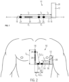
- FIG. 1 illustrates a subcutaneous implantable medical device 10, of the subcutaneous defibrillator type 10.
- the Figure 2 illustrates said subcutaneous implantable medical device 10 in an implanted state.
- the subcutaneous defibrillator 10 comprises a housing 12, pulse generator, to which a subcutaneous implantable probe 14 is connected.
- the subcutaneous implantable probe 14 is at least partially flexible and comprises two ends 16, 18: a proximal end 16 which is connected to the housing 12 and a free distal end 18.
- the subcutaneous implantable probe 14 comprises three detection electrodes 20, 22, 24 and a defibrillation electrode 26.
- the subcutaneous implantable probe 14 could comprise more than three detection electrodes.
- the subcutaneous implantable probe 14 also includes conductive wires (which are not visible) making it possible to electrically connect the electrodes 20, 22, 24 of the probe 14 to electrical contacts (not visible) at the level of the housing 28 - known per se from the current state of the technique.
- the detection electrodes 20, 22, 24 of the subcutaneous implantable probe 14 allow the detection of electrical signals used to infer the cardiac activity of a patient.
- the detection of electrophysiological activity subcutaneously is, however, impaired by numerous artifacts such as muscular electrical noise or interference with the external environment.
- the probe 14 being of the subcutaneous type, the detection electrodes 20, 22, 24 are not in direct contact with the myocardium. Adequate positioning of the detection electrodes 20, 22, 24 makes it possible to improve the quality of the electrophysiological signals detected and collected; which, consequently, makes it possible to improve the quality of detection of the R wave (i.e. the depolarization peak).
- optimal processing of the collected signals makes it possible to further improve the quality of R wave detection.
- the subcutaneous implantable device 10 comprises a specific positioning of the detection electrodes 20, 22, 24.
- a first detection electrode 20 and a second detection electrode 22 are positioned between the housing 12 and the defibrillation electrode 26; while a third detection electrode 24 is placed between the distal end 18 of the probe 14 and the defibrillation electrode 26.
- the defibrillation electrode 26 is thus positioned between the second detection electrode 22 and the third electrode of detection 24.
- the probe comprises in this order: the first detection electrode 20, the second detection electrode 22 , the defibrillation electrode 26 then the third detection electrode 24.
- the first detection electrode 20 and the second detection electrode 22 form a first dipole D1 of length L1.
- the second detection electrode 22 and the third detection electrode 24 form a second dipole D2 of length L2.
- the second dipole D2 can be formed by the third electrode of detection 24 and the first detection electrode 20.
- the housing 12 can serve as an electrode and form a dipole with one of the detection electrodes 20, 22, 24.
- the length L1 of the first dipole D1 is shorter than the length L2 of the second dipole D2.
- the length L1 is between 5 and 50 mm, more particularly between 10 and 20 millimeters, while the length L2 is between 80 and 400 millimeters.
- the distance L3 between the first detection electrode 20 and the housing 12 is between 80 and 300 millimeters.
- the subcutaneous implantable medical device 10 further comprises a controller 28 housed in the housing 12.
- the controller 28 of the device 10 is configured to detect electrophysiological signals recorded simultaneously via the first dipole D1 and the second dipole D2 of the subcutaneous implantable probe. -cutaneous 14.
- the controller 28 is configured to detect the R wave of a cardiac signal at the level of the first dipole D1.
- the first dipole D1 being shorter than the second dipole D2, the first dipole D1 is less exposed to the risk of overdetection, in particular because it is less subject to recording noises of muscular origin.
- the first dipole D1 is positioned during subcutaneous implantation of the device 10 close to and above the cardiac notch of the left lung, called "left lung cardiac notch" in English. This particular position of the first dipole D1 makes it possible to detect an electrophysiological signal with an R wave which is more distinctive compared to the P and T waves; the P and T waves detected at this location being minimized compared to the R wave.
- the active subcutaneous implantable medical device 10 may comprise an accelerometer and/or a gyroscope so that the controller 28 is configured to determine the position of the patient by means of the accelerometer and/or the gyroscope.
- the detection of the R wave via the first dipole could be combined with the detection of cardiac signals on a plurality of "second dipoles", that is to say on a plurality of dipoles which are longer than the first dipole, for example: a dipole formed by the second detection electrode 22 and the third detection electrode 24, a dipole formed by the first detection electrode 20 and the third detection electrode 24 and a dipole formed between the housing 12 and one of the detection electrodes 20, 22, 24.
- the electrical signals collected via the first dipole D1 and via the second dipole D2 serve as input signals to an algorithm to process the signals in order to detect the presence of a tachyarrhythmia. These signals may first be subject to an appropriate preprocessing of filtering, normalization and/or centering, according to known techniques.
- the signal processing method 30 can be applied to the subcutaneous implantable medical device 10 described previously with reference to the Figures 1 and 2 .
- the process 30 illustrated in Figure 3 comprises a first step 100 during which the signals concurrently collected in a time domain via the first dipole D1 and the second dipole D2 are recorded. Said signals can be recorded over a predetermined time window centered on the detected R wave. Alternatively, the signals can be recorded continuously, particularly during periods of suspected tachyarrhythmia.
- the controller 28 of the device 10 may itself include a memory in which said collected signals are stored.
- step 200 the potential presence of a tachyarrhythmia episode is detected based only on the signals collected via the first dipole D1.
- This second step 200 can be based on an analysis of the heart rhythm or heart rate.
- step 200 may include a morphological analysis. If the presence of a tachyarrhythmia episode is not suspected (see arrow 202 on the Figure 3 ), the method 30 returns to the first step 100. Conversely, if the presence of an episode of tachyarrhythmia is suspected (see arrow 204 on the Figure 3 ), the signal processing method 30 continues in a third step 300.
- the following steps of the method for processing signals 30 are not unnecessarily carried out if the presence of a tachyarrhythmia episode is not even suspected. This makes it possible to reduce costs in terms of power and software resources.
- a two-dimensional curve parameterized as a function of time representative of the cardiac activity of a patient is determined by plotting the signals collected via the second dipole as a function of the signals collected via the first dipole.
- a tangent vector at a plurality of points of said two-dimensional curve is determined.
- Said vector can be a normalized vector.
- the third step 300 is followed by a fourth step 400 during which the presence or absence of unwanted noise in the signals collected is identified as a function of the change in sign of at least one of the coordinates of the tangent vector between each successive point of the plurality of points of said two-dimensional curve.
- This method of detecting the presence of unwanted noise makes it possible to reduce calculation costs on the one hand by its low number of steps and the fact that it does not require analysis of the amplitude of the signals collected.
- step 400 is followed by a step 404 in which the unwanted noise component(s) in the collected signals detected in step 400 is/are ignored.
- Step 404 is then followed by the second step 200 (see arrow 406 on the Figure 3 ), as described previously.
- the signal processing method 30 continues in a fifth step 500.
- the presence or absence of a tachyarrhythmia episode is confirmed based on a majority criterion determined according to a similarity criterion between said two-dimensional curve and a two-dimensional reference curve representative of a normal sinus cycle, and further described in the following.
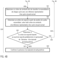
- the signal processing method 30 and its steps 100 to 500 will be further described with reference to the flowchart of the Figures 4a-b .
- the reference numbers having the same hundred digit between them refer to the same step, in particular to one of the steps 100 to 500 described in relation to the Figure 3 and to which reference is made.
- the first step 100 in which the signals concurrently collected in a time domain via the first dipole D1 and the second dipole D2 are recorded, is followed by a step 102, during which, after each detection of a depolarization peak, that is to say after each detection of an R wave, a corresponding beat is isolated by a time window of fixed width and centered on this depolarization peak.
- the time window can for example have a width of 80 to 150 milliseconds centered on the detection of the peak of the R wave, in particular 100 milliseconds, corresponding to 100 points for a sampling frequency of 1000 Hz. This value of 100 milliseconds makes it possible to properly isolate the QRS complex to analyze its morphology.
- the controller 28 of the device 10 is configured to store a plurality of successive detected cycles in memory. Detection of the R wave makes it possible in particular to determine the R-R interval.
- the detection of the R wave is carried out solely from the signals collected via the first dipole D1.
- the detection of the R wave is thus not carried out on the second dipole D2 so as not to add any calculation cost.
- the first dipole D1 being shorter than the second dipole D2, the first dipole D1 is less likely to be altered, in particular because it is less subject to recording noises of muscular origin.
- the position of dipole D1 when the probe is implanted, makes it possible to optimize the detection of the ratio of R/P and R/T waves and thus reduce the risk of overdetection.
- the signals from the second dipole D2 collected concurrently with those from the first dipole D1 are however kept in memory and used in step 300 of the signal processing method 30.
- the potential presence of an episode of tachyarrhythmia is determined: if the R-R interval, calculated at The previous step 102, is below a predetermined tachyarrhythmia threshold, the presence of a tachyarrhythmia episode is suspected.
- the potential presence of a tachyarrhythmia episode can be established by considering a sliding average over a plurality of cycles, for example over 5 to 20 cycles, in particular over 8 cycles.
- the predetermined tachyarrhythmia threshold may be a fixed value or an adjustable value, in particular programmable for each patient.
- the method 30 returns to the first step 100. Conversely, if the presence of an episode of tachyarrhythmia is suspected (see arrow 204 on the Figure 4a ), the signal processing method 30 continues in the third step 300.
- the successive beats recorded simultaneously subcutaneously via the first dipole D1 and the second dipole D2, a fraction of the beats of which is included within the time window comprising the QRS complex and centered on the The R wave, are represented in the form of a two-dimensional curve with the first dipole D1 on the abscissa and the second dipole D2 on the ordinate.
- the second dipole D2 could be on the abscissa and the first dipole D1 on the ordinate.
- Such a two-dimensional curve is shown in Figure 5 .
- the two-dimensional curve is not a closed loop because it only corresponds to part of the complete cardiac loop, i.e. to the isolated QRS complex within the time window.
- step 400 of method 30, in which the presence or absence of unwanted noise in the signals collected is identified comprises three successive sub-steps 401, 403 and 405.
- step 400 the coordinates of a tangent vector at each point of the two-dimensional curve determined in step 300 are calculated.
- the algorithm of method 30 calculates the number of times that at least one of the two coordinates of each tangent vector changes sign between two successive points of the two-dimensional curve.
- the second sub-step 403 thus makes it possible to characterize the curvature of the two-dimensional curve. Indeed, in the case of a non-noisy cardiac cycle, there exists between the signals collected on the two dipoles D1, D2 a relationship which means that the two-dimensional curve is represented in an essentially regular manner. Conversely, in the case of a noisy cardiac cycle, that is to say including artifacts of extracardiac origin, the two-dimensional curve can be represented erratically, as shown in Figure Figure 6 . Such an erratic representation (see Figure 6 ) is then characterized, according to the present invention, by the number of times that at least one of the coordinates of the tangent vector changes sign between each successive point of the two-dimensional curve.
- the algorithm of the method 30 compares this number of sign changes to a predetermined threshold number indicative of unwanted noise.
- This predetermined threshold number indicative of unwanted noise can be defined relative to all of the plurality of points of said two-dimensional curve. Alternatively, this predetermined threshold number indicative of unwanted noise can be defined as an absolute threshold for a certain number of given consecutive points.
- the signal processing method 30 continues in the fifth step 500.
- step 405 of step 400 is followed by a step 404 in which the unwanted noise component(s) in the collected signals detected in step 400 is/are ignored.
- the algorithm triggers a mode called "noise mode", in which parameters, in particular the detection threshold of R waves, are temporarily modified during a certain lapse of time. time, for example for 30 seconds.
- the algorithm in noise mode, extends the refractory periods for a certain predefined period of time.
- Step 404 is followed by step 407 (see arrow 406 on the Figure 4a ) during which the RR interval is calculated again on the signals whose unwanted noise has been ignored and has therefore not been taken into account.
- Step 407 is then followed by step 200, previously described, during which the RR interval of the signals, cleaned of unwanted noise, is compared to a threshold indicative of tachyarrhythmia.
- step 500 of method 30, in which the presence or absence of tachyarrhythmia is confirmed comprises four successive substeps 501, 503, 505, 509.
- step 501 of step 500 where the signals do not include unwanted noise but whose R-R interval is less than the threshold indicative of tachyarrhythmia (see step 200 of method 30), a comparison analysis, in particular similarity, is started.
- the two-dimensional curve determined in step 300 is compared to a two-dimensional reference curve representative of a normal sinus rhythm, for example previously recorded in the memory of controller 28.
- step 501 may include the determination of a similarity criterion by considering, in addition to a normal sinus cycle reference, a reference representative of a "P wave” and a reference representative of a " T wave”.
- step 501 of this variant makes it possible to identify the potential P/T overdetection because there would be both a “similarity to the reference T” or a “similarity to the reference P”.
- a similarity criterion is determined in step 501. According to the similarity criterion, each cycle will be classified either as “resembles normal sinus rhythm” or “does not resemble normal sinus rhythm”.
- the tangent vectors of each curve at each point are determined. Then, an average angle between the tangent vectors of the two curves at each point is determined. Then, a correlation coefficient between the norms of the tangent vectors of the two curves at each point is determined. Finally, the average angle and the correlation coefficient are represented on a graph, as shown in Figure Figure 7 , from which we can determine whether the curves are similar to each other or not.
- the graph of the Figure 7 represents the classification of each cycle as “similar” to the sinus reference or “not similar” to the sinus reference.
- the majority criterion can be a function, on the last N non-noise beats recorded, of the number of cycles Ci similar to those of the reference representative of a normal sinus rhythm.
- the similarity criterion can also be defined by a ratio Ci to N (Ci/N) with N the number of last non-noise beats recorded. The similarity of the cycles with those of the reference is thus determined by means of the similarity criterion in step 501.
- this majority criterion that is to say the value of Ci or the ratio Ci/N, is compared to a predetermined majority threshold representative of the absence of 'an episode of tachyarrhythmia Disf.
- step 505 is followed by the first step 100 of the algorithm (see arrow 506 on the Figure 4b ), that is to say the acquisition of new electrical signals.
- the tachyarrhythmia is confirmed at step 509.
- the algorithm concludes that there is an absence or presence of a tachyarrhythmia episode.
- the two-dimensional reference curve representative of normal sinus rhythm is determined by taking the average and/or the median of the last two cycles of normal sinus rhythm of the patient.
- the controller 28 of the device 10 could further be configured to determine the similarity criterion by comparing said two-dimensional curve to a two-dimensional reference curve in said position determined and representative of a normal sinus rhythm.
- the two-dimensional reference curves determined in normal sinus rhythm for each position can be compared with each other, in order to only remember those which are sufficiently different from one position to another. This allows you to save storage memory.
- the reference curves for each position can be updated, for example daily or weekly.
- the controller 28 of the device 10 can be configured to trigger a defibrillation operation by means of the defibrillation electrode 26 of the subcutaneous implantable probe 14.
- the controller 28 of the device 10 is configured to carry out each of the steps and sub-steps of the method 30.
Landscapes
- Health & Medical Sciences (AREA)
- Life Sciences & Earth Sciences (AREA)
- Cardiology (AREA)
- Engineering & Computer Science (AREA)
- Heart & Thoracic Surgery (AREA)
- Biomedical Technology (AREA)
- Animal Behavior & Ethology (AREA)
- General Health & Medical Sciences (AREA)
- Public Health (AREA)
- Veterinary Medicine (AREA)
- Nuclear Medicine, Radiotherapy & Molecular Imaging (AREA)
- Radiology & Medical Imaging (AREA)
- Physics & Mathematics (AREA)
- Biophysics (AREA)
- Pathology (AREA)
- Medical Informatics (AREA)
- Molecular Biology (AREA)
- Surgery (AREA)
- Artificial Intelligence (AREA)
- Computer Vision & Pattern Recognition (AREA)
- Physiology (AREA)
- Psychiatry (AREA)
- Signal Processing (AREA)
- Electrotherapy Devices (AREA)
- Measurement And Recording Of Electrical Phenomena And Electrical Characteristics Of The Living Body (AREA)
Description
La présente invention se rapporte à un dispositif cardiaque implantable sous cutané, en particulier un défibrillateur implantable sous cutané tel que décrit à la revendication 1.The present invention relates to a subcutaneous implantable cardiac device, in particular a subcutaneous implantable defibrillator as described in
Les défibrillateurs automatiques implantables classiques, c'est-à-dire de type transveineux, aussi abréviés ICD pour « Implantable Cardioverter-Defibrillator » en anglais, comprennent un générateur d'impulsions de défibrillation et une unité de contrôle à microprocesseur logés dans un boîtier métallique généralement implanté de manière sous-cutanée dans la poche pectorale. Ce boîtier est connecté à une ou plusieurs sondes qui sont introduites dans la veine sous-clavière où elles atteignent finalement le coeur. À l'intérieur du coeur, les extrémités distales des sondes sont fixées aux parois internes des cavités cardiaques, où elles peuvent enregistrer des électrogrammes (EGM) reflétant le fonctionnement électrophysiologique du coeur. Sur la base de ceux-ci, un traitement sous forme de défibrillation (choc de défibrillation) est administré (ou interrompu) afin de mettre fin à une tachyarythmie ventriculaire représentant un danger de mort, telle que la tachycardie ventriculaire et la fibrillation ventriculaire.Conventional implantable automatic defibrillators, that is to say of the transvenous type, also abbreviated ICD for “Implantable Cardioverter-Defibrillator” in English, include a defibrillation pulse generator and a microprocessor control unit housed in a metal housing usually implanted subcutaneously in the pectoral pocket. This box is connected to one or more probes which are introduced into the subclavian vein where they ultimately reach the heart. Inside the heart, the distal ends of the leads are attached to the inner walls of the heart chambers, where they can record electrograms (EGMs) reflecting the electrophysiological functioning of the heart. Based on these, treatment in the form of defibrillation (defibrillation shock) is administered (or interrupted) in order to terminate a life-threatening ventricular tachyarrhythmia, such as ventricular tachycardia and ventricular fibrillation.
Les éléments les plus faibles de ces défibrillateurs automatiques implantables transveineux (ainsi que des stimulateurs cardiaques et dispositifs similaires) sont les sondes intracardiaques. La fracture de sonde est d'ailleurs l'une des causes les plus courantes de dysfonctionnement du stimulateur cardiaque. L'extraction d'une sonde ICD (ou d'un stimulateur cardiaque) implantée est une procédure à forte morbidité et mortalité élevée, et est donc généralement uniquement effectuée en cas d'infection systémique grave ne pouvant pas être traitée avec des antibiotiques. Dans la majorité des cas, les sondes fracturées seront déconnectées du dispositif et laissées dans le coeur. Une nouvelle sonde est ensuite implantée à côté de l'ancienne et connectée au défibrillateur automatique implantable. Cependant, cette solution n'est possible que s'il reste encore suffisamment d'espace dans la veine, car la présence de davantage de sondes peut entraîner une occlusion veineuse. Par conséquent, l'utilisation de sondes intracardiaques n'est pas idéalement adaptée à de jeunes patients, qui pourraient avoir besoin d'une multitude de sondes au cours de leur vie.The weakest elements of these transvenous implantable cardioverter defibrillators (as well as pacemakers and similar devices) are the intracardiac leads. Lead fracture is one of the most common causes of pacemaker malfunction. Removal of an implanted ICD lead (or pacemaker) is a procedure with high morbidity and mortality, and is therefore usually only performed in cases of serious systemic infection that cannot be treated with antibiotics. In the majority of cases, the fractured leads will be disconnected from the device and left in the heart. A new lead is then implanted next to the old one and connected to the implantable cardioverter defibrillator. However, this solution is only possible if there is still enough space in the vein, as the presence of more probes can lead to vein occlusion. Therefore, the use of intracardiac leads is not ideally suited to young patients, who may require a multitude of leads during their lifetime.
Une solution aux problèmes associés aux sondes intracardiaques, énumérés ci-dessus, consiste à les remplacer par des sondes sous-cutanées. Ainsi, en l'absence de contact avec le coeur ou le sang, le risque d'infection systémique est éliminé et les veines ne sont plus obstruées. En outre, contrairement aux sondes intracardiaques, l'extraction des sondes sous-cutanées est moins traumatique et ne comporte pas de risque de mortalité, car les sondes sous-cutanées ne touchent pas le coeur. De ce fait, les sondes peuvent être retirées en toute sécurité en cas de fracture et remplacées par de nouvelles sondes sous-cutanées, sans risque pour le patient.One solution to the problems associated with intracardiac leads, listed above, is to replace them with subcutaneous leads. Thus, in the absence of contact with the heart or blood, the risk of systemic infection is eliminated and the veins are no longer obstructed. Furthermore, unlike intracardiac leads, extraction of subcutaneous leads is less traumatic and does not carry a risk of mortality, because the subcutaneous probes do not touch the heart. Therefore, the probes can be safely removed in the event of a fracture and replaced with new subcutaneous probes, without risk to the patient.
Les principaux défis des dispositifs implantables sous-cutanés sont liés à la réduction du rapport signal sur bruit des signaux enregistrés par voie sous-cutanée et à l'augmentation de l'énergie requise pour une défibrillation réussie. Les dispositifs implantables sous-cutanés enregistrent des électrocardiogrammes (ECG) sous-cutanés - plutôt que des EGM - qui capturent une activité électrophysiologique spatialement moyennée en champ lointain. Les ondes P et les ondes T sont alors plus importantes dans les signaux sous-cutanés par rapport aux ondes R, rendant plus difficile la détection de l'intervalle RR sur laquelle de nombreux algorithmes de détection de tachyarythmie sont basés. Les sources de bruit non cardiaques, telles que les myopotentiels, peuvent également altérer les signaux sous-cutanés et interférer avec les algorithmes de détection, ce qui perturbe le traitement. De plus, les signaux sous-cutanés ont tendance à être plus sensibles aux changements de posture que les signaux intracardiaques. Dans l'ensemble, ces difficultés se traduisent par une procédure de détection plus complexe que pour les défibrillateurs automatiques implantables classiques. Des algorithmes ou des procédés de traitement de signaux d'électrogramme endocavitaires, tels que connus de
Du fait des limitations susmentionnées, il y a un besoin d'améliorer le traitement de signaux recueillis via une sonde sous cutanée, en particulier pour pouvoir confirmer la présence ou non d'une tachyarythmie et différencier une surdétection d'ondes T ou P (ou de bruit) d'une tachyarythmie.Due to the aforementioned limitations, there is a need to improve the processing of signals collected via a subcutaneous probe, in particular to be able to confirm the presence or absence of a tachyarrhythmia and to differentiate between overdetection of T or P waves (or noise) of a tachyarrhythmia.
L'objet de la présente invention est donc d'améliorer le traitement des signaux recueillis au moyen d'une sonde sous-cutanée d'un dispositif médical sous cutané, en particulier d'améliorer la sensibilité et la spécificité de la détection et de la discrimination des épisodes de tachyarythmie enregistrés à partir d'une sonde sous-cutanée.The object of the present invention is therefore to improve the processing of signals collected by means of a subcutaneous probe of a subcutaneous medical device, in particular to improve the sensitivity and specificity of the detection and discrimination of tachyarrhythmia episodes recorded from a subcutaneous probe.
L'objet de la présente invention est atteint par un dispositif médical actif implantable sous cutané, en particulier un défibrillateur cardiaque sous cutané, comprenant : un boîtier, une sonde implantable sous cutanée connectée au boîtier, la sonde implantable sous cutanée comprenant une pluralité d'électrodes de détection formant au moins deux dipôles à partir desquels au moins deux signaux électriques sont concurremment recueillis ; le premier dipôle ayant une longueur inférieure à celle du deuxième dipôle ; le dispositif comprenant en outre un contrôleur configuré pour déterminer la présence ou non d'une tachyarythmie en déterminant un critère de similarité à partir des signaux électriques recueillis concurremment via le premier dipôle et via le deuxième dipôle pendant une série définie de cycles cardiaques, telle que la détection d'un pic de dépolarisation, correspondant à la détection d'une onde R, est réalisée via le premier dipôle.The object of the present invention is achieved by an active subcutaneous implantable medical device, in particular a subcutaneous cardiac defibrillator, comprising: a housing, a subcutaneous implantable probe connected to the housing, the subcutaneous implantable probe comprising a plurality of detection electrodes forming at least two dipoles from which at least two electrical signals are concurrently collected; the first dipole having a length less than that of the second dipole; the device further comprising a controller configured to determine the presence or absence of a tachyarrhythmia by determining a similarity criterion from the electrical signals collected concurrently via the first dipole and via the second dipole during a defined series of cardiac cycles, such as the detection of a depolarization peak, corresponding to the detection of an R wave, is carried out via the first dipole.
La détection d'un pic de dépolarisation à partir des signaux recueillis via le premier dipôle permet d'améliorer la qualité de la détection de l'onde R par voie sous-cutanée car le premier dipôle est le plus court des deux dipôles de la sonde sous-cutanée, et, est donc moins exposé au risque de surdétection de bruit ou d'erreur lors de la détection du complexe QRS par rapport au deuxième dipôle. En effet, la distance couverte entre les électrodes du premier dipôle est réduite, ce qui diminue les risques d'altération des signaux par une source externe. Il y a, par exemple, moins de masse musculaire entre les électrodes pouvant introduire des myopotentiels.The detection of a depolarization peak from the signals collected via the first dipole makes it possible to improve the quality of detection of the R wave subcutaneously because the first dipole is the shorter of the two dipoles of the probe subcutaneous, and is therefore less exposed to the risk of overdetection of noise or error when detecting the QRS complex compared to the second dipole. In fact, the distance covered between the electrodes of the first dipole is reduced, which reduces the risk of signal alteration by an external source. There is, for example, less muscle mass between the electrodes that can introduce myopotentials.
La présente invention, relative à un dispositif médical actif implantable sous cutané, peut être davantage améliorée grâce aux modes de réalisation suivants.The present invention, relating to an active medical device implantable under the skin, can be further improved thanks to the following embodiments.
Selon un mode de réalisation de l'invention, les signaux recueillis via le premier dipôle et le deuxième dipôle de la sonde implantable sous cutanée peuvent être considérés sur une fenêtre temporelle comprenant un complexe QRS et centrée sur la détection de l'onde R, la détection de l'onde R étant uniquement réalisée via le premier dipôle.According to one embodiment of the invention, the signals collected via the first dipole and the second dipole of the subcutaneous implantable probe can be considered over a time window comprising a QRS complex and centered on the detection of the R wave, the detection of the R wave being only carried out via the first dipole.
Ainsi, l'intervalle R-R des signaux recueillis via le premier dipôle peut être déterminé et une fenêtre temporelle, par exemple de 80 à 150 millisecondes, en particulier de 100 millisecondes, peut être centrée sur la détection de l'onde R réalisée via le premier dipôle. La détection de l'onde R n'est ainsi pas réalisée sur le deuxième dipôle de manière à ne pas ajouter davantage de coût de calcul. Les signaux du deuxième dipôle recueillis concurremment à ceux du premier dipôle, en particulier uniquement pendant une fenêtre temporelle, peuvent être enregistrés dans la mémoire du dispositif.Thus, the RR interval of the signals collected via the first dipole can be determined and a time window, for example from 80 to 150 milliseconds, in particular 100 milliseconds, can be centered on the detection of the R wave carried out via the first dipole. The detection of the R wave is thus not carried out on the second dipole so as not to add further calculation cost. The signals from the second dipole collected concurrently with those from the first dipole, in particular only during a time window, can be recorded in the memory of the device.
Selon l'invention, le contrôleur est configuré pour combiner les signaux recueillis via le premier dipôle et les signaux recueillis via le deuxième dipôle, et à partir de la représentation des signaux recueillis via le deuxième dipôle en fonction des signaux recueillis via le premier dipôle, de déterminer une courbe bidimensionnelle paramétrée en fonction du temps représentative de l'activité cardiaque d'un patient, le critère de similarité étant défini par la comparaison, en particulier une corrélation, entre ladite courbe bidimensionnelle et une courbe bidimensionnelle de référence représentative en rythme sinusal normal.According to the invention, the controller is configured to combine the signals collected via the first dipole and the signals collected via the second dipole, and from the representation of the signals collected via the second dipole as a function of the signals collected via the first dipole, to determine a two-dimensional curve parameterized as a function of time representative of the cardiac activity of a patient, the similarity criterion being defined by the comparison, in particular a correlation, between said two-dimensional curve and a two-dimensional reference curve representative in sinus rhythm normal.
La détermination de la courbe bidimensionnelle par le contrôleur permet de combiner des signaux recueillis selon le premier dipôle avec ceux recueillis selon le deuxième dipôle : il est ainsi rendu possible de prendre en compte simultanément les informations venant des deux dipôles de la sonde sous-cutanée, notamment en considérant - selon le dipôle - différentes morphologies de signaux électriques, ce qui contribue à l'obtention de paramètres davantage pertinents relatifs à l'origine du signal recueilli. Ces paramètres relatifs à l'origine du signal recueilli participent notamment à la détermination du critère de similarité.The determination of the two-dimensional curve by the controller makes it possible to combine signals collected according to the first dipole with those collected according to the second dipole: it is thus made possible to simultaneously take into account the information coming from the two dipoles of the subcutaneous probe, in particular by considering - depending on the dipole - different morphologies of electrical signals, which contributes to obtaining more relevant parameters relating to the origin of the signal collected. These parameters relating to the origin of the signal collected participate in particular in determining the similarity criterion.
Selon un mode de réalisation de l'invention, le contrôleur peut en outre être configuré pour identifier la présence ou non de bruit indésirable dans les signaux recueillis en fonction du changement de signe d'au moins une des coordonnées d'un vecteur tangent entre chaque point successif d'une pluralité de points de ladite courbe bidimensionnelle. Plus précisément, le contrôleur peut être configuré pour identifier la présence de bruit indésirable en déterminant le nombre de fois qu'au moins une des coordonnées du vecteur tangent change de signe entre chaque point successif de la pluralité de points de ladite courbe bidimensionnelle et en comparant ce nombre à un nombre seuil prédéterminé indicateur de bruit indésirable.According to one embodiment of the invention, the controller can further be configured to identify the presence or absence of unwanted noise in the signals collected as a function of the change in sign of at least one of the coordinates of a tangent vector between each successive point of a plurality of points of said two-dimensional curve. More specifically, the controller can be configured to identify the presence of unwanted noise by determining the number of times that at least one of the coordinates of the tangent vector changes sign between each successive point of the plurality of points of said two-dimensional curve and comparing this number has a predetermined threshold number indicating unwanted noise.
En effet, dans le cas d'un cycle cardiaque non bruité, il existe entre les signaux détectés sur les deux dipôles un rapport qui fait que la courbe bidimensionnelle soit représentée de façon essentiellement régulière. À l'inverse, dans le cas d'un cycle cardiaque bruité, c'est-à-dire comprenant des artefacts d'origine extracardiaque, la courbe bidimensionnelle peut être représentée de façon erratique. Une telle représentation erratique peut être caractérisée par le nombre de fois qu'au moins une des coordonnées du vecteur tangent change de signe entre chaque point successif de la courbe bidimensionnelle. Le contrôleur est ainsi adapté pour identifier la présence de bruit dans les signaux recueillis au moyen d'un calcul rapide et rentable en termes de ressources logicielles. Le contrôleur du dispositif pourrait être configuré pour passer dans un mode dit « mode bruit » pendant un certain lapse de temps, par exemple pendant 30 secondes, en augmentant le seuil de détection des ondes R ou en allongeant les périodes réfractaires.Indeed, in the case of a non-noisy cardiac cycle, there is a relationship between the signals detected on the two dipoles which causes the two-dimensional curve to be represented in an essentially regular manner. Conversely, in the case of a noisy cardiac cycle, that is to say including artifacts of extracardiac origin, the two-dimensional curve can be represented erratically. Such an erratic representation can be characterized by the number of times that at least one of the coordinates of the tangent vector changes sign between each successive point of the two-dimensional curve. The controller is thus adapted to identify the presence of noise in the signals collected by means of a rapid and cost-effective calculation in terms of software resources. The controller of the device could be configured to switch to a so-called “noise mode” for a certain period of time, for example for 30 seconds, by increasing the detection threshold of R waves or by lengthening the refractory periods.
Selon un mode de réalisation de l'invention, le contrôleur peut en outre être configuré pour déterminer la présence ou non d'une tachyarythmie en déterminant un critère de majorité qui est déterminé à partir du critère de similarité en calculant le nombre de cycles semblables entre les signaux recueillis et des signaux de référence représentatifs d'un cycle sinusal normal.According to one embodiment of the invention, the controller can further be configured to determine the presence or absence of a tachyarrhythmia by determining a majority criterion which is determined from the similarity criterion by calculating the number of similar cycles between the signals collected and reference signals representative of a normal sinus cycle.
Ainsi, selon le critère de majorité, la confirmation de la présence d'un épisode de tachyarythmie peut être déduite. Inversement, il peut être conclu à une surdétection de l'onde T ou/et de l'onde P, ce qui ne requiert pas de traitement particulier. Le dispositif est ainsi configuré pour pouvoir différencier une surdétection d'ondes T ou P (ou de bruit) d'une tachyarythmie ; ce qui est nécessaire dans le cas particulier des défibrillateurs sous-cutanés qui sont davantage susceptibles à la surdétection de bruit et/ou des ondes P, T que les défibrillateurs transveineux.Thus, according to the majority criterion, confirmation of the presence of a tachyarrhythmia episode can be inferred. Conversely, it can be concluded that there is overdetection of the T wave and/or the P wave, which does not require any particular treatment. The device is thus configured to be able to differentiate overdetection of T or P waves (or noise) from a tachyarrhythmia; which is necessary in the particular case of subcutaneous defibrillators which are more susceptible to overdetection of noise and/or P, T waves than transvenous defibrillators.
Selon un mode de réalisation de l'invention, la sonde implantable sous cutanée peut en outre comprendre une électrode de défibrillation. De plus, le contrôleur peut être configuré pour déclencher une opération de défibrillation au moyen de l'électrode de défibrillation lorsque le critère de similarité indique la présence d'une tachyarythmie à traiter.According to one embodiment of the invention, the subcutaneous implantable probe may further comprise a defibrillation electrode. Additionally, the controller may be configured to trigger a defibrillation operation using the defibrillation electrode when the similarity criterion indicates the presence of a tachyarrhythmia to be treated.
Ainsi, le dispositif médical implantable sous cutanée est adapté non seulement pour détecter un épisode de tachyarythmie mais également pour traiter une telle condition, en délivrant si nécessaire des impulsions électriques de défibrillation.Thus, the subcutaneous implantable medical device is suitable not only for detecting an episode of tachyarrhythmia but also for treating such a condition, by delivering electrical defibrillation pulses if necessary.
Selon un mode de réalisation de l'invention, le dispositif médical actif implantable sous cutané comprend en outre un accéléromètre ou/et un gyroscope de manière à ce que le contrôleur est configuré pour déterminer la position du patient au moyen de l'accéléromètre ou/et du gyroscope ;
le contrôleur étant en outre configuré pour déterminer le critère de similarité en comparant ladite courbe bidimensionnelle à une courbe bidimensionnelle de référence dans ladite position déterminée et représentative en rythme sinusal normal.According to one embodiment of the invention, the subcutaneous implantable active medical device further comprises an accelerometer and/or a gyroscope so that the controller is configured to determine the position of the patient by means of the accelerometer or/ and gyroscope;
the controller being further configured to determine the similarity criterion by comparing said two-dimensional curve to a two-dimensional reference curve in said determined and representative position in normal sinus rhythm.
Les signaux sous-cutanés sont plus sensibles à la posture que les signaux endocavitaires. Ainsi, en permettant la détection de la position du patient, l'interprétation des signaux électriques recueillis peut être davantage affinée, et donc améliorée.Subcutaneous signals are more sensitive to posture than intracavitary signals. Thus, by allowing the detection of the patient's position, the interpretation of the electrical signals collected can be further refined, and therefore improved.
Est aussi divulgué ici, un procédé, mis en oeuvre par le controleur, pour traiter des signaux électriques recueillis concurremment sur un premier dipôle et un deuxième dipôle formés par des électrodes d'une sonde implantable sous cutanée d'un dispositif médical implantable sous cutané dans le domaine temporel pendant une série définie de cycles cardiaques, comprenant les étapes de : 1) déterminer une courbe bidimensionnelle paramétrée en fonction du temps représentative de l'activité cardiaque d'un patient en traçant les signaux recueillis via le deuxième dipôle en fonction des signaux recueillis via le premier dipôle et déterminer un vecteur tangent en une pluralité de point de ladite courbe bidimensionnelle ; et 2) identifier la présence ou non de bruit indésirable dans les signaux recueillis en fonction du changement de signe d'au moins une des coordonnées du vecteur tangent entre chaque point successif de la pluralité de points de ladite courbe bidimensionnelle ; et/ou 3) confirmer la présence ou non d'un épisode de tachyarythmie selon un critère de similarité entre ladite courbe bidimensionnelle et une courbe bidimensionnelle de référence représentative d'un rythme sinusal normal.Also disclosed here is a method, implemented by the controller, for processing electrical signals collected concurrently on a first dipole and a second dipole formed by electrodes of a subcutaneous implantable probe of a subcutaneous implantable medical device in the time domain during a defined series of cardiac cycles, comprising the steps of: 1) determining a parameterized two-dimensional curve as a function of time representative of the cardiac activity of a patient by plotting the signals collected via the second dipole as a function of the signals collected via the first dipole and determining a tangent vector at a plurality of points of said two-dimensional curve; and 2) identify the presence or absence of unwanted noise in the signals collected as a function of the change in sign of at least one of the coordinates of the tangent vector between each successive point of the plurality of points of said two-dimensional curve; and/or 3) confirm the presence or absence of an episode of tachyarrhythmia according to a criterion of similarity between said two-dimensional curve and a two-dimensional reference curve representative of a normal sinus rhythm.
L'étape 1) de détermination de la courbe bidimensionnelle permet de combiner des signaux recueillis selon un premier dipôle avec ceux recueillis selon un deuxième dipôle : il est ainsi rendu possible de prendre en compte simultanément les informations venant de deux dipôles d'une sonde sous-cutanée, notamment en considérant - selon le dipôle - différentes morphologies de signaux électriques, ce qui contribue à l'obtention de paramètres davantage pertinents relatifs à l'origine du signal recueilli. De plus, les signaux recueillis par voie sous-cutanée étant particulièrement exposés à des bruits indésirables, l'étape 2) du procédé permet d'identifier la présence ou non de bruit indésirable, et ce, au moyen de cette même courbe bidimensionnelle, ce qui permet de réduire les coûts de calcul en termes de ressources logicielles, parce que les cycles bruités ne sont pas traités ou pris en considération lors du traitement des signaux recueillis. Enfin, l'étape 3) du procédé permet d'effectuer la discrimination entre présence ou non d'une tachyarythmie, cette discrimination étant opérée elle-aussi à partir de ladite courbe bidimensionnelle. Le procédé de traitement de signaux de la présente invention est ainsi spécifiquement adapté et optimisé pour un dispositif médical implantable sous-cutané.Step 1) of determining the two-dimensional curve makes it possible to combine signals collected according to a first dipole with those collected according to a second dipole: it is thus made possible to simultaneously take into account the information coming from two dipoles of a probe under -cutaneous, in particular by considering - depending on the dipole - different morphologies of electrical signals, which contributes to obtaining more relevant parameters relating to the origin of the signal collected. Furthermore, the signals collected subcutaneously being particularly exposed to unwanted noise, step 2) of the method makes it possible to identify the presence or absence of unwanted noise, by means of this same two-dimensional curve, this which makes it possible to reduce calculation costs in terms of software resources, because noisy cycles are not processed or taken into consideration during the processing of the collected signals. Finally, step 3) of the method makes it possible to discriminate between the presence or absence of a tachyarrhythmia, this discrimination also being carried out from said two-dimensional curve. The signal processing method of the present invention is thus specifically adapted and optimized for a subcutaneous implantable medical device.
Le procédé, mis en oeuvre par le controleur, pour traiter des signaux électriques, peut être davantage amélioré grâce aux modes de réalisation suivants.The method, implemented by the controller, for processing electrical signals, can be further improved thanks to the following embodiments.
Selon un mode de réalisation, l'étape 1) du procédé peut être précédée d'une étape initiale d'analyse, en particulier une analyse du rythme cardiaque et/ou de la fréquence cardiaque, afin de détecter la présence potentielle d'un épisode de tachyarythmie dans les signaux recueillis, tel qu'à l'étape initiale d'analyse les signaux recueillis via l'un des dipôles de la sonde implantable sous cutanée sont comparés à un seuil prédéterminé de tachyarythmie.According to one embodiment, step 1) of the method can be preceded by an initial analysis step, in particular an analysis of the heart rate and/or heart rate, in order to detect the potential presence of an episode. of tachyarrhythmia in the signals collected, such that at the initial analysis step the signals collected via one of the dipoles of the subcutaneous implantable probe are compared to a predetermined tachyarrhythmia threshold.
En particulier, cette étape initiale de comparaison est mise en oeuvre pour les signaux du dipôle qui comprend la détection du complexe QRS, en particulier la détection de l'onde R. Cette étape initiale de comparaison comprend ainsi la comparaison de l'intervalle R-R avec le seuil prédéterminé de tachyarythmie. Cette étape ne nécessitant que la détection de l'onde R sur un des deux dipôles, les coûts de calcul du procédé selon la présente invention peuvent être minimisés.In particular, this initial comparison step is implemented for the dipole signals which includes the detection of the QRS complex, in particular the detection of the R wave. This initial comparison step thus includes the comparison of the RR interval with the predetermined tachyarrhythmia threshold. This step only requiring the detection of the R wave on one of the two dipoles, the calculation costs of the method according to the present invention can be minimized.
Selon un mode de réalisation, l'étape 1), l'étape 2) et/ou l'étape 3) peuvent être réalisées seulement si la présence potentielle d'un épisode de tachyarythmie dans les signaux recueillis est détectée à l'étape initiale d'analyse.According to one embodiment, step 1), step 2) and/or step 3) can be carried out only if the potential presence of a tachyarrhythmia episode in the signals collected is detected at the initial step. analysis.
Ainsi, les étapes 1), 2) et 3) du procédé pour traiter des signaux ne sont pas réalisées systématiquement mais que si la présence d'un épisode de tachyarythmie est suspectée. Cela permet de réduire davantage les coûts de calcul du procédé, en évitant des étapes de calculs inutiles.Thus, steps 1), 2) and 3) of the method for processing signals are not carried out systematically but only if the presence of an episode of tachyarrhythmia is suspected. This makes it possible to further reduce the calculation costs of the process, by avoiding unnecessary calculation steps.
Selon un mode de réalisation, à l'étape 2) la présence de bruit indésirable peut être identifiée si le nombre de fois qu'au moins une des coordonnées du vecteur tangent change de signe entre chaque point successif de la pluralité de points de ladite courbe bidimensionnelle est supérieur à un nombre seuil prédéterminé indicateur de bruit indésirable. En effet, dans le cas d'un cycle cardiaque non bruité, il existe entre les signaux détectés sur les deux dipôles un rapport qui fait que la courbe bidimensionnelle soit représentée de façon essentiellement régulière. À l'inverse, dans le cas d'un cycle cardiaque bruité, c'est-à-dire comprenant des artefacts d'origine extracardiaque, la courbe bidimensionnelle peut être représentée de façon erratique. Une telle représentation erratique peut être caractérisée par le nombre de fois qu'au moins une des coordonnées du vecteur tangent change de signe entre chaque point successif de la courbe bidimensionnelle. L'étape 2) du procédé fournit ainsi une étape de calcul rapide et rentable pour l'identification de bruit indésirable dans les signaux.According to one embodiment, in step 2) the presence of unwanted noise can be identified if the number of times that at least one of the coordinates of the tangent vector changes sign between each successive point of the plurality of points of said curve two-dimensional is greater than a predetermined threshold number indicating unwanted noise. Indeed, in the case of a non-noisy cardiac cycle, there is a relationship between the signals detected on the two dipoles which causes the two-dimensional curve to be represented in an essentially regular manner. Conversely, in the case of a noisy cardiac cycle, that is to say including artifacts of extracardiac origin, the two-dimensional curve can be represented erratically. Such an erratic representation can be characterized by the number of times that at least one of the coordinates of the tangent vector changes sign between each successive point of the two-dimensional curve. Step 2) of the method thus provides a rapid and cost-effective calculation step for the identification of unwanted noise in signals.
Selon un mode de réalisation, le nombre seuil prédéterminé indicateur de bruit indésirable peut être défini relativement à la totalité de la pluralité de points de ladite courbe bidimensionnelle.According to one embodiment, the predetermined threshold number indicative of unwanted noise can be defined relative to all of the plurality of points of said two-dimensional curve.
Ainsi, l'identification de bruit indésirable peut être déterminée de manière exhaustive en considérant tous les points de la pluralité de points de la courbe bidimensionnelle, c'est-à-dire en prenant en compte l'information contenue à chaque point de la courbe.Thus, the identification of unwanted noise can be determined exhaustively by considering all the points of the plurality of points of the two-dimensional curve, that is to say by taking into account the information contained at each point of the curve .
Selon un mode de réalisation, l'étape 3) peut être réalisée à partir de signaux dans lesquels la présence potentielle d'un épisode de tachyarythmie a été détectée à l'étape initiale d'analyse ; et dans lesquels du bruit indésirable n'a pas été identifié à l'étape 2.According to one embodiment, step 3) can be carried out from signals in which the potential presence of a tachyarrhythmia episode has been detected at the initial analysis step; and in which unwanted noise was not identified in
Afin de pallier aux limitations spécifiquement liées aux signaux recueillis par voie sous-cutanée, comme la surdétection de bruit, le procédé garantit que l'étape pour confirmer la présence ou non d'un épisode de tachyarythmie ne soit enclenchée que pour des signaux d'un cycle considéré valide à l'étape 2), c'est-à-dire pour des signaux d'un cycle non-bruité.In order to overcome the limitations specifically linked to signals collected subcutaneously, such as overdetection of noise, the method guarantees that the step to confirm the presence or not of an episode of tachyarrhythmia is only initiated for signals of tachyarrhythmia. a cycle considered valid in step 2), that is to say for signals of a non-noise cycle.
Selon un mode de réalisation, l'identification de la présence de bruit indésirable à l'étape 2) peut être suivie d'une étape de traitement des signaux durant laquelle les cycles cardiaques identifiés comme bruité à l'étape 2) sont ignorés; puis à nouveau de l'étape initiale d'analyse.According to one embodiment, the identification of the presence of unwanted noise in step 2) can be followed by a signal processing step during which the cardiac cycles identified as noisy in step 2) are ignored; then again from the initial analysis step.
Ainsi, la présence de bruits indésirables dans les signaux recueillis ne rend pas nécessairement les signaux inutilisables.Thus, the presence of unwanted noise in the collected signals does not necessarily render the signals unusable.
Selon un mode de réalisation, l'étape 3) peut comprendre en outre la détermination d'un critère de majorité qui est déterminé à partir du critère de similarité en déterminant le nombre de cycles semblables entre les signaux recueillis et des signaux de référence représentatifs d'un cycle sinusal normal. De plus, selon un mode de réalisation, le critère de majorité peut être comparé à un seuil de majorité prédéterminé et représentatif de la présence d'un épisode de tachyarythmie permettant de confirmer la présence ou non d'un épisode de tachyarythmie.According to one embodiment, step 3) may further comprise the determination of a majority criterion which is determined from the similarity criterion by determining the number of similar cycles between the signals collected and reference signals representative of a normal sinus cycle. Furthermore, according to one embodiment, the majority criterion can be compared to a predetermined majority threshold representative of the presence of an episode of tachyarrhythmia making it possible to confirm the presence or not of an episode of tachyarrhythmia.
Ainsi, selon le critère de majorité et la valeur du seuil de majorité défini, la confirmation de la présence d'un épisode de tachyarythmie peut être déduite. Inversement, il peut être conclu à une surdétection de l'onde T ou/et de l'onde P, ce qui ne requiert pas de traitement particulier. Le procédé de traitement des signaux permet ainsi de différencier une surdétection d'ondes T ou P (ou de bruit) d'une tachyarythmie ; ce qui est nécessaire dans le cas particulier des défibrillateurs sous-cutanés qui sont davantage susceptibles à la surdétection de bruit et/ou des ondes P, T que les défibrillateurs transveineux. L'invention et ses avantages seront expliqués plus en détail dans la suite au moyen de modes de réalisation préférés et en s'appuyant notamment sur les figures d'accompagnement suivantes, dans laquelle :
-
Figure 1 représente une vue schématisée d'un dispositif implantable sous cutané selon la présente invention ; -
Figure 2 représente une vue schématisée et par transparence du dispositif implanté sous cutané selon la présente invention implanté chez un patient; -
Figure 3 représente un organigramme du procédé pour traiter des signaux -
Figure 4a représente un organigramme détaillé du procédé pour traiter des signaux qui est représenté à laFigure 3 ; -
Figure 4b représente un organigramme détaillé du procédé pour traiter des signaux qui est représenté à laFigure 3 ; -
Figure 5 représente une courbe bidimensionnelle d'un cycle non-bruité; -
Figure 6 représente une courbe bidimensionnelle d'un cycle bruité ; -
Figure 7 représente une distribution définie pour discriminer la présence de tachyarythmie. -
Figure 8 représente un signal classifié comme rythme sinusal normal selon le procédé de la présente invention; -
Figure 9 représente un signal classifié comme un événement de tachycardie selon le procédé;
-
Figure 1 represents a schematic view of a subcutaneous implantable device according to the present invention; -
Figure 2 represents a schematic and transparent view of the subcutaneously implanted device according to the present invention implanted in a patient; -
Figure 3 represents a flowchart of the method for processing signals -
Figure 4a represents a detailed flowchart of the method for processing signals which is shown inFigure 3 ; -
Figure 4b represents a detailed flowchart of the method for processing signals which is shown inFigure 3 ; -
Figure 5 represents a two-dimensional curve of a non-noise cycle; -
Figure 6 represents a two-dimensional curve of a noisy cycle; -
Figure 7 represents a distribution defined to discriminate the presence of tachyarrhythmia. -
Figure 8 represents a signal classified as normal sinus rhythm according to the method of the present invention; -
Figure 9 represents a signal classified as a tachycardia event according to the method;
L'invention va maintenant être décrite plus en détail en utilisant des modes de réalisation avantageux d'une manière exemplaire et en référence aux figures. Les modes de réalisation décrits sont simplement des configurations possibles et il faut garder à l'esprit que les caractéristiques individuelles telles que décrites ci-dessus peuvent être fournies indépendamment les unes des autres ou peuvent être omises tout à fait lors de la mise en oeuvre de la présente invention.The invention will now be described in more detail using advantageous embodiments in an exemplary manner and with reference to the figures. The embodiments described are merely possible configurations and it should be kept in mind that individual features as described above may be provided independently of each other or may be omitted altogether when implementing the the present invention.
La
Le défibrillateur sous cutané 10 comprend un boîtier 12, générateur d'impulsions, auquel est relié une sonde implantable sous cutanée 14.The
La sonde implantable sous cutanée 14 est au moins partiellement souple et comprend deux extrémités 16, 18 : une extrémité proximale 16 qui est connectée au boîtier 12 et une extrémité distale libre 18.The subcutaneous
Dans le mode de réalisation illustrée aux
La sonde implantable sous cutanée 14 comprend également des fils conducteurs (qui ne sont pas visibles) permettant de connecter électriquement les électrodes 20, 22, 24 de la sonde 14 à des contacts électriques (non visibles) au niveau du boîtier 28 - connu en soi de l'état actuel de la technique.The subcutaneous
Les électrodes de détection 20, 22, 24 de la sonde implantable sous-cutanée 14 permettent la détection de signaux électriques utilisés pour déduire l'activité cardiaque d'un patient.The
La détection d'activité électrophysiologique par voie sous cutanée est cependant altérée par de nombreux artefacts comme des bruits électriques musculaires ou des interférences avec le milieu extérieur. De plus, la sonde 14 étant de type sous cutanée, les électrodes de détection 20, 22, 24 ne sont pas en contact direct avec le myocarde. Un positionnement adéquat des électrodes de détection 20, 22, 24 permet d'améliorer la qualité des signaux électrophysiologiques détectés et recueillis ; ce qui, en conséquence, permet d'améliorer la qualité de la détection de l'onde R (c'est-à-dire le pic de dépolarisation). De plus, un traitement optimal des signaux recueillis permet d'améliorer davantage la qualité de la détection de l'onde R.The detection of electrophysiological activity subcutaneously is, however, impaired by numerous artifacts such as muscular electrical noise or interference with the external environment. In addition, the
Afin d'améliorer la détection de l'onde R et de minimiser celle des ondes cardiaques P et T, notamment pour faciliter la mesure de l'intervalle R-R, le dispositif implantable sous-cutané 10 comprend un positionnement spécifique des électrodes de détection 20, 22, 24. Précisément, tel qu'illustré aux
Le positionnement spécifique des électrodes de détection 20, 22, 24 va être décrit en terme de longueur en référence à la
La première électrode de détection 20 et la deuxième électrode de détection 22 forment un premier dipôle D1 de longueur L1.The
Selon le mode de réalisation illustrée par les
La longueur L1 du premier dipôle D1 est plus courte que la longueur L2 du deuxième dipôle D2. En particulier, la longueur L1 est compris entre 5 et 50 mm, plus en particulier entre 10 et 20 millimètres, tandis que la longueur L2 est comprise entre 80 et 400 millimètres. De plus, la distance L3 entre la première électrode de détection 20 et le boîtier 12 est comprise entre 80 et 300millimètres.The length L1 of the first dipole D1 is shorter than the length L2 of the second dipole D2. In particular, the length L1 is between 5 and 50 mm, more particularly between 10 and 20 millimeters, while the length L2 is between 80 and 400 millimeters. In addition, the distance L3 between the
Le dispositif médical implantable sous-cutané 10 comprend en outre un contrôleur 28 logé dans le boîtier 12. Le contrôleur 28 du dispositif 10 est configuré pour détecter des signaux électrophysiologiques enregistrés simultanément via le premier dipôle D1 et le deuxième dipôle D2 de la sonde implantable sous-cutanée 14. Le contrôleur 28 est configuré pour détecter l'onde R d'un signal cardiaque au niveau du premier dipôle D1.The subcutaneous implantable
Le premier dipôle D1 étant plus court que le deuxième dipôle D2, le premier dipôle D1 est moins exposé au risque de surdétection, notamment car il est moins sujet à enregistrer des bruits d'origine musculaire. De plus, le premier dipôle D1 est positionné lors de l'implantation sous-cutanée du dispositif 10 proche et au-dessus de l'encoche cardiaque du poumon gauche, appelée « left lung cardiac notch » en anglais. Cette position particulière du premier dipôle D1 permet de détecter un signal électrophysiologique avec une onde R qui soit davantage distinctif par rapport aux ondes P et T ; les ondes P et T détectées à cet endroit étant minimisées par rapport à l'onde R.The first dipole D1 being shorter than the second dipole D2, the first dipole D1 is less exposed to the risk of overdetection, in particular because it is less subject to recording noises of muscular origin. In addition, the first dipole D1 is positioned during subcutaneous implantation of the
Dans un autre mode de réalisation, le dispositif médical actif implantable sous cutané 10 peut comprendre un accéléromètre ou/et un gyroscope de manière à ce que le contrôleur 28 soit configuré pour déterminer la position du patient au moyen de l'accéléromètre ou/et du gyroscope.In another embodiment, the active subcutaneous implantable
Dans un autre mode de réalisation, la détection de l'onde R via le premier dipôle pourrait être combinée à la détection de signaux cardiaques sur une pluralité de « deuxièmes dipôles », c'est-à-dire sur une pluralité de dipôles qui soient plus longs que le premier dipôle, par exemple : un dipôle formé par la deuxième électrode de détection 22 et la troisième électrode de détection 24, un dipôle formé par la première électrode de détection 20 et la troisième électrode de détection 24 et un dipôle formé entre le boîtier 12 et l'une des électrodes de détection 20, 22, 24.In another embodiment, the detection of the R wave via the first dipole could be combined with the detection of cardiac signals on a plurality of "second dipoles", that is to say on a plurality of dipoles which are longer than the first dipole, for example: a dipole formed by the
Les signaux électriques recueillis via le premier dipôle D1 et via le deuxième dipôle D2 servent de signaux d'entrée à un algorithme pour procéder au traitement des signaux dans le but de détecter la présence d'une tachyarythmie. Ces signaux peuvent préalablement faire l'objet d'un prétraitement approprié de filtrage, normalisation et/ou centrage, selon des techniques connues.The electrical signals collected via the first dipole D1 and via the second dipole D2 serve as input signals to an algorithm to process the signals in order to detect the presence of a tachyarrhythmia. These signals may first be subject to an appropriate preprocessing of filtering, normalization and/or centering, according to known techniques.
Ce procédé de traitement de signaux est décrit dans ce qui suit de manière générale en référence à la
Le procédé de traitement de signaux 30 peut être appliqué au dispositif médical implantable sous cutané 10 décrit précédemment en référence aux
Le procédé 30 illustré à la
Au cours d'une deuxième étape 200 du procédé 30, la présence potentielle d'un épisode de tachyarythmie est détectée en fonction seulement des signaux recueillis via le premier dipôle D1. Cette deuxième étape 200 peut être basée sur une analyse du rythme cardiaque ou de la fréquence cardiaque. Dans une variante, l'étape 200 peut comprendre une analyse morphologique. Si la présence d'un épisode de tachyarythmie n'est pas suspectée (voir la flèche 202 sur la
A la troisième étape 300, une courbe bidimensionnelle paramétrée en fonction du temps représentative de l'activité cardiaque d'un patient est déterminée en traçant les signaux recueillis via le deuxième dipôle en fonction des signaux recueillis via le premier dipôle. De plus, un vecteur tangent en une pluralité de point de ladite courbe bidimensionnelle est déterminé. Ledit vecteur peut être un vecteur normalisé.In the
La troisième étape 300 est suivie d'une quatrième étape 400 au cours de laquelle la présence ou non de bruit indésirable dans les signaux recueillis est identifiées en fonction du changement de signe d'au moins une des coordonnées du vecteur tangent entre chaque point successif de la pluralité de points de ladite courbe bidimensionnelle. Ce procédé de détection de la présence de bruit indésirable permet de réduire les coûts de calcul d'une part par son faible nombre d'étapes et du fait qu'il ne requiert pas une analyse de l'amplitude des signaux recueillis.The
Si la présence de bruit indésirable est détectée (voir la flèche 402 sur la
A la cinquième étape 500, la présence ou non d'un épisode de tachyarythmie est confirmée à partir d'un critère de majorité déterminé selon un critère de similarité entre ladite courbe bidimensionnelle et une courbe bidimensionnelle de référence représentative d'un cycle sinusal normal, et davantage décrit dans ce qui suit.In the
Le procédé de traitement signal 30 et ses étapes 100 à 500 vont être davantage décrits en référence à l'organigramme des
La première étape 100, à laquelle les signaux concurremment recueillis dans un domaine temporel via le premier dipôle D1 et le deuxième dipôle D2 sont enregistrés, est suivie par une étape 102, au cours de laquelle, après chaque détection d'un pic de dépolarisation, c'est-à-dire après chaque détection d'une onde R, un battement correspondant est isolé par une fenêtre temporelle de largeur fixe et centrée sur ce pic de dépolarisation. La fenêtre temporelle peut par exemple avoir une largeur de 80 à 150 millisecondes centrée sur la détection du pic de l'onde R, en particulier de 100 millisecondes, correspondant à 100 points pour une fréquence d'échantillonnage de 1000 Hz. Cette valeur de 100 millisecondes permet de bien isoler le complexe QRS pour en analyser la morphologie. Le contrôleur 28 du dispositif 10 est configuré pour garder en mémoire une pluralité de cycles détectés successifs. La détection de l'onde R permet notamment de déterminer l'intervalle R-R.The
Selon un mode de réalisation avantageux de la présente invention, la détection de l'onde R est uniquement réalisée à partir des signaux recueillis via le premier dipôle D1. La détection de l'onde R n'est ainsi pas réalisée sur le deuxième dipôle D2 de manière à ne pas ajouter de coût de calcul. De plus, le premier dipôle D1 étant plus court que le deuxième dipôle D2, le premier dipôle D1 est moins d'être altéré, notamment car il est moins sujet à enregistrer des bruits d'origine musculaire. En effet, la géométrie du premier dipôle D1 de longueur L1=5 à 50mm, en particulier L1=10 à 20mm, permet de rendre le premier dipôle D1 moins sujet aux myopotentiels. De plus, la position du dipôle D1, lorsque la sonde est implantée, permet d'optimiser la détection du ratio des ondes R/P et R/T et ainsi de réduire le risque de surdétection. Les signaux du deuxième dipôle D2 recueillis concurremment à ceux du premier dipôle D1 sont toutefois gardés en mémoire et utilisés à l'étape 300 du procédé de traitement de signaux 30.According to an advantageous embodiment of the present invention, the detection of the R wave is carried out solely from the signals collected via the first dipole D1. The detection of the R wave is thus not carried out on the second dipole D2 so as not to add any calculation cost. Furthermore, the first dipole D1 being shorter than the second dipole D2, the first dipole D1 is less likely to be altered, in particular because it is less subject to recording noises of muscular origin. Indeed, the geometry of the first dipole D1 of length L1=5 at 50mm, in particular L1=10 to 20mm, makes the first dipole D1 less subject to myopotentials. In addition, the position of dipole D1, when the probe is implanted, makes it possible to optimize the detection of the ratio of R/P and R/T waves and thus reduce the risk of overdetection. The signals from the second dipole D2 collected concurrently with those from the first dipole D1 are however kept in memory and used in
Au cours de la deuxième étape 200 du procédé 30, la présence potentielle d'un épisode de tachyarythmie, basée seulement sur les intervalles R-R des signaux recueillis via le dipôle le plus court D1, est déterminée : si l'intervalle R-R, calculé à l'étape précédente 102, est inférieur à un seuil prédéterminé de tachyarythmie, la présence d'un épisode de tachyarythmie est suspectée. Dans une variante, la présence potentielle d'un épisode de tachyarythmie peut être établie en considérant une moyenne glissante sur une pluralité de cycles, par exemple sur 5 à 20 cycles, en particulier sur 8 cycles. Le seuil prédéterminé de tachyarythmie peut être une valeur fixe ou une valeur ajustable, en particulier programmable pour chaque patient.During the
Tel qu'expliqué en référence à la
A la troisième étape 300, les battements successifs enregistrés simultanément par voie sous-cutanée via le premier dipôle D1 et le deuxième dipôle D2, dont une fraction des battements est comprise à l'intérieur de la fenêtre temporelle comprenant le complexe QRS et centrée sur l'onde R, sont représentés sous forme d'une courbe bidimensionnelle avec le premier dipôle D1 en abscisse et le deuxième dipôle D2 en ordonnée. Dans une variante, le deuxième dipôle D2 pourrait être en abscisse et le premier dipôle D1 en ordonnée. Une telle courbe bidimensionnelle est représentée à la
L'analyse bidimensionnelle des signaux recueillis, c'est-à-dire en deux dimensions, ne doit pas être entendue de manière en elle-même limitative, l'invention s'appliquant aussi bien à une analyse dans un espace multidimensionnel d'ordre supérieur (3D ou plus), par extrapolation des enseignements de la présente description à une situation où des signaux sont recueillis de manière sous-cutanée concurremment sur trois dipôles ou plus.The two-dimensional analysis of the signals collected, that is to say in two dimensions, should not be understood as limiting in itself, the invention applying equally well to an analysis in a multidimensional space of order higher (3D or more), by extrapolation of the teachings of the present description to a situation where signals are collected subcutaneously concurrently on three or more dipoles.
Comme montré par la
A la première sous-étape 401 de l'étape 400, les coordonnées d'un vecteur tangent en chaque point de la courbe bidimensionnelle déterminée à l'étape 300, sont calculées.In the first substep 401 of
A la deuxième sous-étape 403 de l'étape 400, l'algorithme du procédé 30 calcule le nombre de fois qu'au moins une des deux coordonnées de chaque vecteur tangent change de signe entre deux points successifs de la courbe bidimensionnelle.In the
La deuxième sous-étape 403 permet ainsi de caractériser la courbure de la courbe bidimensionnelle. En effet, dans le cas d'un cycle cardiaque non bruité, il existe entre les signaux recueillis sur les deux dipôles D1, D2 une relation qui fait que la courbe bidimensionnelle est représentée de façon essentiellement régulière. À l'inverse, dans le cas d'un cycle cardiaque bruité, c'est-à-dire comprenant des artefacts d'origine extracardiaque, la courbe bidimensionnelle peut être représentée de façon erratique, tel que représenté à la
A la troisième sous-étape 405 de l'étape 400, l'algorithme du procédé 30 compare ce nombre de changement de signe à un nombre seuil prédéterminé indicatif de bruit indésirable. Ce nombre seuil prédéterminé indicatif de bruit indésirable peut être défini relativement à la totalité de la pluralité de points de ladite courbe bidimensionnelle. Dans une variante, ce nombre seuil prédéterminé indicatif de bruit indésirable peut être défini comme un seuil absolu pour un certain nombre de points consécutifs donnés.In the
Si la présence de bruit indésirable dans les signaux n'est pas détectée (voir la flèche 408 sur les
A l'inverse, si la présence de bruit indésirable est détectée dans les signaux (voir la flèche 402 sur la
L'étape 404 est suivie d'une étape 407 (voir la flèche 406 sur la
Comme montré à la
A la première sous-étape 501 de l'étape 500, où les signaux ne comprennent pas de bruit indésirable mais dont l'intervalle R-R est inférieur au seuil indicatif de tachyarythmie (voir étape 200 du procédé 30), une analyse de comparaison, en particulier de similarité, est démarrée. Ainsi, à la sous-étape 501, la courbe bidimensionnelle déterminée à l'étape 300 est comparée à une courbe bidimensionnelle de référence représentative d'un rythme sinusal normal, par exemple préalablement enregistrée dans la mémoire du contrôleur 28.In the
Dans une variante, l'étape 501 peut comprendre la détermination d'un critère de similarité en considérant, en plus d'une référence en cycle sinusale normale, une référence représentative d'une « onde P » et une référence représentative d'une « onde T ». Ainsi, l'étape 501 de cette variante permet d'identifier la surdétection potentielle P/T car il y aurait à la fois une « similarité à la référence T » ou une « similarité à la référence P ».In a variant,
Afin de classifier la ressemblance de chaque cycle avec la référence représentative d'un rythme sinusal normal, un critère de similarité est déterminé à l'étape 501. Selon le critère de similarité, chaque cycle sera classifié soit en « ressemble au rythme sinusal normal » soit en « ne ressemble pas au rythme sinusal normal ».In order to classify the resemblance of each cycle with the reference representative of a normal sinus rhythm, a similarity criterion is determined in
Pour déterminer le critère de similarité, les vecteurs tangents de chaque courbe en chaque point sont déterminés. Puis, un angle moyen entre les vecteurs tangents des deux courbes en chaque point est déterminé. Ensuite, un coefficient de corrélation entre les normes des vecteurs tangents des deux courbes en chaque point est déterminé. Enfin, l'angle moyen et le coefficient de corrélation sont représentés sur un graphique, tel qu'illustré à la
Le critère de majorité peut être fonction, sur les N derniers battements non-bruités enregistrés, du nombre de cycles Ci similaires à ceux de la référence représentative d'un rythme sinusal normal. Dans une variante, le critère de similarité peut également être défini par un ratio Ci sur N (Ci/N) avec N le nombre de derniers battements non-bruités enregistrés. La similarité des cycles avec ceux de la référence est ainsi déterminée au moyen du critère de similarité à l'étape 501.The majority criterion can be a function, on the last N non-noise beats recorded, of the number of cycles Ci similar to those of the reference representative of a normal sinus rhythm. In a variant, the similarity criterion can also be defined by a ratio Ci to N (Ci/N) with N the number of last non-noise beats recorded. The similarity of the cycles with those of the reference is thus determined by means of the similarity criterion in
A une sous-étape 505 de l'étape 500, ce critère de majorité, c'est-à-dire la valeur de Ci ou le ratio Ci/N, est comparé à un seuil de majorité prédéterminé et représentatif de l'absence d'un épisode de tachyarythmie Créf.At a
Si une majorité de cycles similaires à la référence sinusale (par exemple 8 Ci sur les 12 derniers cycles) est détectée, alors la présence tachyarythmie n'est pas confirmée. Le procédé 30 est alors réinitialisé de sorte que l'étape 505 est suivie de la première étape 100 de l'algorithme (voir la flèche 506 sur la
Au contraire, s'il n'y a pas une majorité de cycles similaires à la référence sinusale (par exemple 2 Ci sur les 12 derniers cycles), alors la tachyarythmie est confirmée à l'étape 509.On the contrary, if there are not a majority of cycles similar to the sinus reference (for example 2 Ci over the last 12 cycles), then the tachyarrhythmia is confirmed at
Ainsi, selon que le critère de majorité franchisse un seuil prédéterminé Créf, l'algorithme conclut à l'absence ou la présence d'un épisode de tachyarythmie.Thus, depending on whether the majority criterion crosses a predetermined threshold Créf, the algorithm concludes that there is an absence or presence of a tachyarrhythmia episode.
La
Dans la deuxième série de 8 battements illustrée à la
Dans le cas où Créf est prédéterminé comme une valeur supérieure ou égale à 3/8, alors l'algorithme ne confirme pas le présence d'un épisode de tachyarythmie suite à l'analyse de la première série de battement et la deuxième série de battement de la
La
La courbe bidimensionnelle de référence représentative d'un rythme sinusal normal est déterminée en faisant la moyenne ou/et la médiane des au moins deux derniers cycles de rythme sinusal normal du patient.The two-dimensional reference curve representative of normal sinus rhythm is determined by taking the average and/or the median of the last two cycles of normal sinus rhythm of the patient.
Dans un mode de réalisation où le dispositif médical implantable sous cutanée 10 comprend un accéléromètre et/ou gyroscope, le contrôleur 28 du dispositif 10 pourrait en outre être configuré pour déterminer le critère de similarité en comparant ladite courbe bidimensionnelle à une courbe bidimensionnelle de référence dans ladite position déterminée et représentative d'un rythme sinusal normal. Ainsi, en permettant la détection de la position du patient, l'interprétation des signaux électriques recueillis peut être davantage affinée, et donc améliorée. De plus, les courbes bidimensionnelles de référence déterminées en rythme sinusal normal pour chaque position peuvent être comparées entre elles, afin de ne garder en mémoire que celles qui sont suffisamment différentes d'une position à l'autre. Cela permet notamment d'économiser de la mémoire de stockage. En outre, les courbes de référence pour chaque position peuvent être actualisées, par exemple de manière journalière ou hebdomadaire.In one embodiment where the subcutaneous implantable
A la suite de l'étape 509, le contrôleur 28 du dispositif 10 peut être configuré pour déclencher une opération de défibrillation au moyen de l'électrode de défibrillation 26 de la sonde implantable sous cutanée 14.Following
Le contrôler 28 du dispositif 10 est configuré pour réaliser chacune des étapes et sous-étapes du procédé 30.The
Claims (7)
- A subcutaneous implantable active medical device, in particular a subcutaneous cardiac defibrillator, comprising:a housing (12);a subcutaneous implantable lead (14) connected to the housing (12);the subcutaneous implantable lead (14) comprising a plurality of sensing electrodes (20, 22, 24) forming at least two dipoles (D1, D2) from which at least two electrical signals are collected concurrently;the first dipole (D1) having a length (L1) less than a length (L2) of the second dipole (D2);the subcutaneous implantable active medical device further comprising a controller (28) configured to combine the signals collected via the first dipole (D1) and the signals collected via the second dipole (D2), andon the basis of the representation of the signals collected via the second dipole (D2) as a function of the signals collected via the first dipole (D1), to determine a two-dimensional curve that is parameterized as a function of time and that is representative of the cardiac activity of a patient,the controller being configured to determine whether or not tachyarrhythmia is present by determining a criterion of similarity based on the electrical signals collected concurrently via the first dipole (D1) and via the second dipole (D2) during a defined series of cardiac cycles that is such that detection of a depolarization peak,corresponding to detection of an R wave, is performed via the first dipole (D1),the criterion of similarity being defined by a comparison between said two-dimensional curve and a reference two-dimensional curve representative of a normal sinus rhythm.
- The subcutaneous implantable active medical device of claim 1, wherein the signals collected via the first dipole (D1) and via the second dipole (D2) of the subcutaneous implantable lead (14) are considered over a time window comprising a QRS complex and centered on the detection of the R wave,
the detection of the R wave being performed via the first dipole (D1) only. - The subcutaneous implantable active medical device of any of claims 1 and 2, wherein the controller (28) is further configured to identify a presence or absence of undesirable noise in the collected signals as a function of the change of sign of at least one of the coordinates of a tangent vector between each successive point of a plurality of points of said two-dimensional curve,
the controller (28) being configured to identify the presence of undesirable noise by determining the number of times at least one of the coordinates of the tangent vector changes sign between each successive point of the plurality of points of said two-dimensional curve and by comparing said number with a predetermined threshold number indicative of undesirable noise. - The subcutaneous implantable active medical device of any of the preceding claims, wherein the controller (28) is further configured to determine the presence or absence of tachyarrhythmia by determining a criterion of majority that is determined on the basis of the criterion of similarity by computing the number of cycles that are similar between the collected signals and reference signals that are representative of a normal sinus cycle.
- The subcutaneous implantable active medical device of any of claims 1 to 4, wherein the subcutaneous implantable lead (14) further comprises a defibrillation electrode (26).
- The subcutaneous implantable active medical device of claim 5, wherein the controller (28) is configured to trigger a defibrillation operation by means of the defibrillation electrode (26) when the criterion of similarity indicates the presence of tachyarrhythmia to be treated.
- The subcutaneous implantable active medical device of any of claims 1 to 6, further comprising an accelerometer and/or a gyroscope in such a manner that the controller (28) is configured to determine a position of the patient by means of the accelerometer and/or of the gyroscope,
the controller being further configured to determine the criterion of similarity by comparing said two-dimensional curve with a reference two-dimensional curve in said determined position, which reference two-dimensional curve is representative of a normal sinus rhythm.
Applications Claiming Priority (1)
| Application Number | Priority Date | Filing Date | Title |
|---|---|---|---|
| FR1907534 | 2019-07-05 |
Publications (2)
| Publication Number | Publication Date |
|---|---|
| EP3760114A1 EP3760114A1 (en) | 2021-01-06 |
| EP3760114B1 true EP3760114B1 (en) | 2024-01-24 |
Family
ID=68425053
Family Applications (1)
| Application Number | Title | Priority Date | Filing Date |
|---|---|---|---|
| EP20183499.1A Active EP3760114B1 (en) | 2019-07-05 | 2020-07-01 | Subcutaneous implantable medical device for processing signals from a subcutaneous implantable medical device |
Country Status (4)
| Country | Link |
|---|---|
| US (1) | US20210001136A1 (en) |
| EP (1) | EP3760114B1 (en) |
| JP (1) | JP7080930B2 (en) |
| CN (1) | CN112169176B (en) |
Family Cites Families (15)
| Publication number | Priority date | Publication date | Assignee | Title |
|---|---|---|---|---|
| US7392085B2 (en) | 2001-11-21 | 2008-06-24 | Cameron Health, Inc. | Multiple electrode vectors for implantable cardiac treatment devices |
| US7130677B2 (en) | 2002-12-04 | 2006-10-31 | Medtronic, Inc. | Methods and apparatus for discriminating polymorphic tachyarrhythmias from monomorphic tachyarrhythmias facilitating detection of fibrillation |
| US20040230230A1 (en) | 2003-04-11 | 2004-11-18 | Lindstrom Curtis Charles | Methods and systems involving subcutaneous electrode positioning relative to a heart |
| US8577455B2 (en) * | 2005-01-18 | 2013-11-05 | Medtronic, Inc. | Method and apparatus for arrhythmia detection in a medical device |
| ATE502339T1 (en) * | 2008-03-28 | 2011-04-15 | Ela Medical Sa | ACTIVE MEDICAL DEVICE CONTAINING IMPROVED MEANS FOR DISTINCTING BETWEEN TACHYCARDIAS OF VENTRICULAR ORIGIN AND TACHYCARDIAS OF SUPRAVENTRICULAR ORIGIN |
| EP2324885B1 (en) * | 2009-11-18 | 2018-10-24 | Sorin CRM SAS | Active medical device including means for capture testing through cardiac vectogram analysis |
| FR2957512A1 (en) | 2010-03-22 | 2011-09-23 | Sorin Crm Sas | ACTIVE MEDICAL DEVICE COMPRISING MEANS FOR DETECTING AND FILTERING ARTIFACTS BY ANALYZING THE HEART VECTOGRAM |
| EP2742971B1 (en) * | 2012-12-14 | 2015-10-21 | Sorin CRM SAS | Active implantable medical device such as a pacemaker with capture testing by simplified analysis of a vector cardiogram |
| US10556117B2 (en) * | 2013-05-06 | 2020-02-11 | Medtronic, Inc. | Implantable cardioverter-defibrillator (ICD) system including substernal pacing lead |
| FR3034319A1 (en) | 2015-04-02 | 2016-10-07 | Sorin Crm Sas | ACTIVE IMPLANTABLE MEDICAL DEVICE WITH BIVENTRICULAR STIMULATION, COMPRISING MEANS FOR MEASURING INTERVENTRICULAR CONDUCTION TIME FOR DIAGNOSING CARDIAC DECOMPENSATION. |
| WO2017121702A1 (en) * | 2016-01-11 | 2017-07-20 | Sorin Crm Sas | Active implantable medical defibrillation device, including improved means for discriminating between external noise and probe breakage and for characterising tachyarrhythmias |
| US20180028087A1 (en) * | 2016-07-27 | 2018-02-01 | Medtronic, Inc. | Cardiac electrical signal gross morphology-based noise detection for rejection of ventricular tachyarrhythmia detection |
| US10987517B2 (en) * | 2017-03-15 | 2021-04-27 | Medtronic, Inc. | Detection of noise signals in cardiac signals |
| US10888697B2 (en) * | 2017-08-18 | 2021-01-12 | Cardiac Pacemakers, Inc. | Fixation mechanism for an implantable lead |
| CN111246909B (en) | 2017-10-17 | 2024-03-08 | 美敦力公司 | Bundle of his and bundle branch pacing adjustment |
-
2020
- 2020-07-01 EP EP20183499.1A patent/EP3760114B1/en active Active
- 2020-07-02 US US16/920,103 patent/US20210001136A1/en active Pending
- 2020-07-03 JP JP2020115480A patent/JP7080930B2/en active Active
- 2020-07-06 CN CN202010641487.7A patent/CN112169176B/en active Active
Also Published As
| Publication number | Publication date |
|---|---|
| CN112169176B (en) | 2024-05-24 |
| EP3760114A1 (en) | 2021-01-06 |
| US20210001136A1 (en) | 2021-01-07 |
| CN112169176A (en) | 2021-01-05 |
| JP7080930B2 (en) | 2022-06-06 |
| JP2021035491A (en) | 2021-03-04 |
Similar Documents
| Publication | Publication Date | Title |
|---|---|---|
| EP2324885B1 (en) | Active medical device including means for capture testing through cardiac vectogram analysis | |
| EP2510974B1 (en) | Active medical device, in particular an implantable defibrillator, with detection of QRS complexes in a signal with a lot of interference | |
| FR2901146A1 (en) | ACTIVE IMPLANTABLE MEDICAL DEVICE FOR CARDIAC STIMULATION, RESYNCHRONIZATION, CARDIOVERSION AND / OR DEFIBRILLATION, COMPRISING MEANS FOR DETECTING VENTRICULAR NOISE ARTEFACTS | |
| EP2105843B1 (en) | Active medical device comprising perfected means for distinguishing between tachycardia with ventricular causes and tachycardia with supraventricular causes | |
| EP0813888A1 (en) | Defibrillator/cardioverter type active medical device with improved discrimination of tachycardia | |
| FR2808102A1 (en) | SYSTEM AND METHOD FOR CLASSIFYING DETECTED EAR EVENTS IN A CARDIOSTIMULATION SYSTEM | |
| EP2368493B1 (en) | Active medical device including means for detecting and filtering artefacts by cardiac vector diagram analysis | |
| FR2808212A1 (en) | Heart pacemaker has measurement and setting of noise threshold avoids false events | |
| EP2742971B1 (en) | Active implantable medical device such as a pacemaker with capture testing by simplified analysis of a vector cardiogram | |
| EP3669773B1 (en) | Device and method for detecting ventricular fibrillation | |
| EP1857143B1 (en) | Active implantable medical device for cardiac stimulation, resynchronisation, cardioversion and/or defibrillation, comprising means for detecting catheter fractures | |
| EP2742973A1 (en) | Active implantable medical device such as a pacemaker with anodal stimulation detection by vector cardiogram analysis | |
| EP3081257B1 (en) | Active implantable medical device for cardiac stimulation comprising means for detecting a remodelling or reverse remodelling phenomenon of the patient | |
| EP3760114B1 (en) | Subcutaneous implantable medical device for processing signals from a subcutaneous implantable medical device | |
| FR2809630A1 (en) | ACTIVE IMPLANTABLE MEDICAL DEVICE SUCH AS CARDIAC STIMULATOR, DEFIBRILLATOR, CARDIOVERTER AND / OR MULTISITE DEVICE WITH PERFECTED DETECTION OF LATE EXTRASYSTOLES | |
| EP2684515B1 (en) | Active medical device comprising means for monitoring the condition of a patient suffering from a risk of heart failure | |
| EP2596832B1 (en) | Implantable cardioverter-defibrillator medical device with dynamically adjustable ventricular sensing threshold | |
| EP3402397B1 (en) | Active implantable medical defibrillation device, including improved means for discriminating between external noise and probe breakage and for characterising tachyarrhythmias | |
| EP2332462B1 (en) | Single-chamber implantable cardioverter/defibrillator with detection of atrial activity via the single-body probe | |
| EP3075413B1 (en) | Implantable medical device for biventricular stimulation, including means for measuring intraventricular conduction time for diagnosis of heart decompensation | |
| EP3760277B1 (en) | Subcutaneous implantable cardiac defibrillation system | |
| EP3165160B1 (en) | Active implantable medical device comprising means for detecting and quantifying fusion situations | |
| EP1118349B1 (en) | One-piece probe for medical active device as implantable defibrillator/cardioverter | |
| EP4329614A1 (en) | Process for assigning an item of identification information to a signal from a cardiac electrode |
Legal Events
| Date | Code | Title | Description |
|---|---|---|---|
| PUAI | Public reference made under article 153(3) epc to a published international application that has entered the european phase |
Free format text: ORIGINAL CODE: 0009012 |
|
| STAA | Information on the status of an ep patent application or granted ep patent |
Free format text: STATUS: THE APPLICATION HAS BEEN PUBLISHED |
|
| AK | Designated contracting states |
Kind code of ref document: A1 Designated state(s): AL AT BE BG CH CY CZ DE DK EE ES FI FR GB GR HR HU IE IS IT LI LT LU LV MC MK MT NL NO PL PT RO RS SE SI SK SM TR |
|
| AX | Request for extension of the european patent |
Extension state: BA ME |
|
| STAA | Information on the status of an ep patent application or granted ep patent |
Free format text: STATUS: REQUEST FOR EXAMINATION WAS MADE |
|
| 17P | Request for examination filed |
Effective date: 20210706 |
|
| RBV | Designated contracting states (corrected) |
Designated state(s): AL AT BE BG CH CY CZ DE DK EE ES FI FR GB GR HR HU IE IS IT LI LT LU LV MC MK MT NL NO PL PT RO RS SE SI SK SM TR |
|
| REG | Reference to a national code |
Ref document number: 602020024715 Country of ref document: DE Ref country code: DE Ref legal event code: R079 Free format text: PREVIOUS MAIN CLASS: A61B0005042000 Ipc: A61B0005283000 |
|
| P01 | Opt-out of the competence of the unified patent court (upc) registered |
Effective date: 20230714 |
|
| GRAP | Despatch of communication of intention to grant a patent |
Free format text: ORIGINAL CODE: EPIDOSNIGR1 |
|
| STAA | Information on the status of an ep patent application or granted ep patent |
Free format text: STATUS: GRANT OF PATENT IS INTENDED |
|
| RIC1 | Information provided on ipc code assigned before grant |
Ipc: A61B 5/363 20210101ALI20230822BHEP Ipc: A61B 5/352 20210101ALI20230822BHEP Ipc: A61B 5/30 20210101ALI20230822BHEP Ipc: A61B 5/00 20060101ALI20230822BHEP Ipc: A61N 1/05 20060101ALI20230822BHEP Ipc: A61N 1/39 20060101ALI20230822BHEP Ipc: A61B 5/283 20210101AFI20230822BHEP |
|
| INTG | Intention to grant announced |
Effective date: 20230918 |
|
| GRAS | Grant fee paid |
Free format text: ORIGINAL CODE: EPIDOSNIGR3 |
|
| GRAA | (expected) grant |
Free format text: ORIGINAL CODE: 0009210 |
|
| STAA | Information on the status of an ep patent application or granted ep patent |
Free format text: STATUS: THE PATENT HAS BEEN GRANTED |
|
| AK | Designated contracting states |
Kind code of ref document: B1 Designated state(s): AL AT BE BG CH CY CZ DE DK EE ES FI FR GB GR HR HU IE IS IT LI LT LU LV MC MK MT NL NO PL PT RO RS SE SI SK SM TR |
|
| REG | Reference to a national code |
Ref country code: GB Ref legal event code: FG4D Free format text: NOT ENGLISH |
|
| REG | Reference to a national code |
Ref country code: CH Ref legal event code: EP |
|
| REG | Reference to a national code |
Ref country code: IE Ref legal event code: FG4D Free format text: LANGUAGE OF EP DOCUMENT: FRENCH |
|
| REG | Reference to a national code |
Ref country code: DE Ref legal event code: R096 Ref document number: 602020024715 Country of ref document: DE |
|
| REG | Reference to a national code |
Ref country code: LT Ref legal event code: MG9D |