EP3757347B1 - Circulation control valve and associated method - Google Patents
Circulation control valve and associated method Download PDFInfo
- Publication number
- EP3757347B1 EP3757347B1 EP20191449.6A EP20191449A EP3757347B1 EP 3757347 B1 EP3757347 B1 EP 3757347B1 EP 20191449 A EP20191449 A EP 20191449A EP 3757347 B1 EP3757347 B1 EP 3757347B1
- Authority
- EP
- European Patent Office
- Prior art keywords
- valve
- annulus
- flow passage
- closure device
- fluid communication
- Prior art date
- Legal status (The legal status is an assumption and is not a legal conclusion. Google has not performed a legal analysis and makes no representation as to the accuracy of the status listed.)
- Active
Links
- 238000000034 method Methods 0.000 title claims description 19
- 239000012530 fluid Substances 0.000 claims description 37
- 238000004891 communication Methods 0.000 claims description 27
- 238000006073 displacement reaction Methods 0.000 claims description 15
- 230000002265 prevention Effects 0.000 claims 2
- 238000010276 construction Methods 0.000 description 7
- 239000002184 metal Substances 0.000 description 7
- 239000004568 cement Substances 0.000 description 5
- 238000007789 sealing Methods 0.000 description 5
- 238000010008 shearing Methods 0.000 description 3
- IJGRMHOSHXDMSA-UHFFFAOYSA-N Atomic nitrogen Chemical compound N#N IJGRMHOSHXDMSA-UHFFFAOYSA-N 0.000 description 2
- 230000009286 beneficial effect Effects 0.000 description 2
- 239000011261 inert gas Substances 0.000 description 2
- 238000004519 manufacturing process Methods 0.000 description 2
- 229920001296 polysiloxane Polymers 0.000 description 2
- 230000000717 retained effect Effects 0.000 description 2
- 241000282472 Canis lupus familiaris Species 0.000 description 1
- 208000032368 Device malfunction Diseases 0.000 description 1
- 230000007423 decrease Effects 0.000 description 1
- 230000002706 hydrostatic effect Effects 0.000 description 1
- 238000009434 installation Methods 0.000 description 1
- 229910052757 nitrogen Inorganic materials 0.000 description 1
- 238000003825 pressing Methods 0.000 description 1
Images


Classifications
-
- E—FIXED CONSTRUCTIONS
- E21—EARTH OR ROCK DRILLING; MINING
- E21B—EARTH OR ROCK DRILLING; OBTAINING OIL, GAS, WATER, SOLUBLE OR MELTABLE MATERIALS OR A SLURRY OF MINERALS FROM WELLS
- E21B34/00—Valve arrangements for boreholes or wells
- E21B34/06—Valve arrangements for boreholes or wells in wells
- E21B34/10—Valve arrangements for boreholes or wells in wells operated by control fluid supplied from outside the borehole
-
- E—FIXED CONSTRUCTIONS
- E21—EARTH OR ROCK DRILLING; MINING
- E21B—EARTH OR ROCK DRILLING; OBTAINING OIL, GAS, WATER, SOLUBLE OR MELTABLE MATERIALS OR A SLURRY OF MINERALS FROM WELLS
- E21B21/00—Methods or apparatus for flushing boreholes, e.g. by use of exhaust air from motor
- E21B21/10—Valve arrangements in drilling-fluid circulation systems
- E21B21/103—Down-hole by-pass valve arrangements, i.e. between the inside of the drill string and the annulus
-
- E—FIXED CONSTRUCTIONS
- E21—EARTH OR ROCK DRILLING; MINING
- E21B—EARTH OR ROCK DRILLING; OBTAINING OIL, GAS, WATER, SOLUBLE OR MELTABLE MATERIALS OR A SLURRY OF MINERALS FROM WELLS
- E21B33/00—Sealing or packing boreholes or wells
- E21B33/10—Sealing or packing boreholes or wells in the borehole
- E21B33/13—Methods or devices for cementing, for plugging holes, crevices or the like
- E21B33/14—Methods or devices for cementing, for plugging holes, crevices or the like for cementing casings into boreholes
-
- E—FIXED CONSTRUCTIONS
- E21—EARTH OR ROCK DRILLING; MINING
- E21B—EARTH OR ROCK DRILLING; OBTAINING OIL, GAS, WATER, SOLUBLE OR MELTABLE MATERIALS OR A SLURRY OF MINERALS FROM WELLS
- E21B34/00—Valve arrangements for boreholes or wells
- E21B34/06—Valve arrangements for boreholes or wells in wells
- E21B34/14—Valve arrangements for boreholes or wells in wells operated by movement of tools, e.g. sleeve valves operated by pistons or wire line tools
-
- E—FIXED CONSTRUCTIONS
- E21—EARTH OR ROCK DRILLING; MINING
- E21B—EARTH OR ROCK DRILLING; OBTAINING OIL, GAS, WATER, SOLUBLE OR MELTABLE MATERIALS OR A SLURRY OF MINERALS FROM WELLS
- E21B2200/00—Special features related to earth drilling for obtaining oil, gas or water
- E21B2200/06—Sleeve valves
Definitions
- the present disclosure relates generally to equipment utilized and operations performed in conjunction with a subterranean well, and more particularly provides a circulation control valve and associated method.
- WO/9902817A1 discloses a sliding sleeve provided to control the flow of fluids through a tubular conduit.
- FIG. 1 Representatively illustrated in FIG. 1 is a well system and associated method 10 which embody principles of the present disclosure.
- a tubular string 12 is installed in a wellbore 14, thereby forming an annulus 16 exterior to the tubular string.
- the wellbore 14 could be lined with casing or liner, in which case the annulus 16 may be formed between the tubular string 12 and the casing or liner.
- the tubular string 12 could be a production tubing string which is cemented in the wellbore 14 to form what is known to those skilled in the art as a "cemented completion.” This term describes a well completion in which production tubing is cemented in an otherwise uncased wellbore. However, it should be clearly understood that the present disclosure is not limited in any way to use in cemented completions, or to any other details of the well system 10 or method described herein.
- a circulation control valve 18 is provided in the well system 10.
- openings 20 in the valve 18 are opened to permit circulation flow between the annulus 16 and an interior flow passage 22 of the tubular string 12. After circulation flow is no longer desired, the openings 20 in the valve 18 are closed.
- valve 18 is representatively illustrated at an enlarged scale and in greater detail.
- the valve 18 may be used in the well system 10 and associated method as described above but does not fall within the scope of the claimed invention.
- valve 18 is in a run-in closed configuration in which flow through the openings 20 between the flow passage 22 and the annulus 16 is prevented.
- this configuration of the valve 18 would be used when the tubular string 12 is installed in the wellbore 14, and when cement is flowed into the annulus 16.
- the valve 18 may be open when cement is flowed into the annulus 16.
- a generally tubular closure device 24 in the form of a sleeve is reciprocably displaceable within an outer housing assembly 26 of the valve 18 in order to selectively permit and prevent fluid flow through the openings 20.
- the closure device 24 carries flexible or resilient seals 28 thereon for sealing across the openings 20, but in an important feature of the example of FIGS. 2A-D , a metal-to-metal seal 30 is also provided to ensure against leakage in the event that the other seals 28 fail.
- FIGS. 5A-D Another internal sleeve 36 and additional seals 32 are provided, so that the openings 20 can be sealed off positively.
- the sleeve 36 can be displaced from within the flow passage 22, for example, using a conventional shifting tool engaged with an internal shifting profile 34 in the sleeve.
- the sleeve 36 is depicted in its closed position in FIGS. 5A-D .
- the metal-to-metal seal 30 is enhanced by operation of a sealing device 40 which includes an arrangement of pistons 38, 42 and a biasing device 44.
- a sealing device 40 which includes an arrangement of pistons 38, 42 and a biasing device 44.
- at least one of the pistons 38, 42 applies a biasing force to the metal-to-metal seal 30 whether pressure in the flow passage 22 is greater than pressure in the annulus 16, or pressure in the annulus is greater than pressure in the flow passage.
- This feature of the sealing device 40 is due to a unique configuration of differential piston areas on the pistons 38, 42.
- the pistons 38, 42 when pressure in the flow passage 22 is greater than pressure in the annulus 16, the pistons will be biased downwardly as viewed in the drawing, thereby applying a downwardly biasing force to the metal-to-metal seal 30.
- the biasing device 44 is used to exert an initial biasing force to the metal-to-metal seal 30.
- a snap ring 46 installed in the housing assembly 26 limits upward displacement of the closure device 24 and limits downward displacement of the pistons 38, 40.
- the closure device 24 is biased upwardly by means of a pressurized internal chamber 48.
- the chamber 48 could, for example, contain nitrogen or another inert gas at a pressure exceeding any hydrostatic pressure expected to be experienced at the valve 18 in the wellbore 14.
- Other compressible fluids, such as silicone, etc., could be used in the chamber 48, if desired.
- the seals 28, 32 on the lower end of the closure device 24 close off an upper end of the chamber 48.
- the upper end of the closure device 24 is exposed to pressure in the flow passage 22.
- the device 54 includes one or more pin or lug(s) 50 secured to the housing assembly 26, and a sleeve 56 rotationally attached to the closure device 24, with the sleeve having one or more profile(s) 52 formed thereon for engagement by the lug.
- valve 18 is representatively illustrated in a configuration in which pressure in the flow passage 22 has been increased to a level greater than the pressure in the chamber 48.
- the closure device 24 has displaced downwardly relative to the housing assembly 26, and fluid flow through the openings 20 is now permitted.
- FIG. 6 An enlarged scale view of the sleeve 56 and profile 52 thereon is representatively illustrated in FIG. 6 .
- the lug 50 can displace relative to the profile 52 between several portions 52a-f of the profile.
- the lug 50 is engaged in a generally straight longitudinally extending profile portion 52b.
- the lug 50 will be engaged in profile portion 52d (with the valve 18 being open). Subsequent release of the increased pressure in the flow passage 22 will cause the lug 50 to engage profile portion 52a, thereby maintaining the valve 18 in its open configuration.
- valve 18 is representatively illustrated after the second application of increased pressure to the flow passage 22, and then release of the increased pressure as described above.
- the valve 18 is now in a closed configuration, in which fluid communication between the flow passage 22 and annulus 16 via the openings 20 is prevented by the closure device 24.
- the profile 52 could be otherwise configured, for example, as a continuous J-slot type profile, to allow multiple openings and closings of the valve 18.
- the closure device 24 can be repeatedly displaced upward and downward to close and open the valve 18 in response to multiple applications and releases of pressure in the flow passage 22, if the profile 52 is appropriately configured.
- valve 18 is representatively illustrated in a closed configuration in which the internal sleeve 36 has been displaced upwardly, so that it now blocks flow through the openings 20 between the annulus 16 and flow passage 22.
- Displacement of the sleeve 36 may be accomplished by any of a variety of means, but preferably a conventional wireline or tubing conveyed shifting tool is used.
- the sleeve 36 may be displaced as a contingency operation, in the event that one or more of the seals 28, 32 leak, or the closure device 24 is otherwise not operable to prevent fluid communication between the flow passage 22 and the annulus 16 via the openings 20.
- Seal bores 58 and a latching profile 60 may also (or alternatively) be provided for installation of a conventional packoff sleeve, if desired.
- FIGS. 7A-D an alternate configuration of the circulation control valve 18 is representatively illustrated, which does not fall within the scope of the claimed invention.
- the configuration of FIGS.7A-D is similar in many respects to the configuration described above, most notably in that both configurations open in response to application of a pressure increase to the flow passage 22, and then close following application of a subsequent pressure increase to the flow passage.
- valve devices 62, 64 to control displacement of the closure device 24.
- the valve devices 62, 64 could be, for example, conventional rupture disks, shear pinned shuttle valves or any other type of valve devices which open in response to application of a certain pressure differential.
- the valve devices 62, 64 are selected to isolate respective internal chambers 66, 68 from well pressure until corresponding predetermined differential pressures are applied across the valve devices, at which point the devices open and permit fluid communication therethrough.
- a radially enlarged piston 70 on the closure device 24 is exposed to the chamber 66 on its upper side, and a lower side of the piston is exposed to another chamber 72.
- Another radially enlarged piston 74 on a sleeve 78 positioned below the closure device 24 is exposed to the chamber 68 on its lower side, and an upper side of the piston is exposed to another chamber 76.
- All of the chambers 66, 68, 72, 76 initially preferably contain a compressible fluid (such as air) at a relatively low pressure (such as atmospheric pressure).
- a compressible fluid such as air
- a relatively low pressure such as atmospheric pressure
- other fluids such as inert gases, silicone fluid, etc.
- other pressures may be used, if desired.
- the closure device 24 is initially maintained in its closed position by one or more shear pins 80.
- pressure in the flow passage 22 is increased to achieve a predetermined pressure differential (from the flow passage to the chamber 66)
- the valve device 62 will open and admit the well pressure into the chamber 66.
- the resulting pressure differential across the piston 70 (between the chambers 66, 72) will cause a downwardly directed biasing force to be exerted on the closure device 24, thereby shearing the shear pins 80 and downwardly displacing the closure device.
- valve 18 is representatively illustrated after the closure device 24 has displaced downwardly following opening of the valve device 62. Fluid communication between the flow passage 22 and the annulus 16 via the openings 20 is now permitted.
- pressure in the flow passage 22 and annulus 16 may be increased to a predetermined pressure differential (from the annulus to the chamber 68) to open the valve device 64.
- a predetermined pressure differential from the annulus to the chamber 68
- the valve device 64 is physically exposed to the annulus 16, rather than to the flow passage 22, and so the valve device is not in fluid communication with the flow passage until the closure device 24 is displaced downwardly to open the valve 18.
- the predetermined pressure differential used for opening the valve device 64 it is not necessary for the predetermined pressure differential used for opening the valve device 64 to be greater than the predetermined pressure differential used for opening the valve device 62.
- valve device 64 When the valve device 64 opens, well pressure will be admitted into the chamber 68, and the resulting pressure differential (between the chambers 68, 76) across the piston 74 will cause an upwardly directed biasing force to be exerted on the sleeve 78.
- the sleeve 78 will displace upwardly and contact the closure device 24. Since the piston 74 has a greater differential piston area than that of the piston 70, the upwardly directed biasing force due to the pressure differential across the piston 74 will exceed the downwardly directed biasing force due to the pressure differential across the piston 70, and the closure device 24 will displace upwardly as a result.
- valve 18 is representatively illustrated after the closure device 24 has displaced upwardly following opening of the valve device 64.
- the closure device 24 again prevents fluid communication between the flow passage 22 and the annulus 16 via the openings 20.
- a snap ring 82 carried on the sleeve 78 now engages an internal profile 84 formed in the housing assembly 26 to prevent subsequent downward displacement of the closure device 24.
- an internal sleeve 36 and/or latching profile 60 and seal bores 58 may be provided for ensuring that the openings 20 can be sealed off as a contingency measure, or as a matter of course when operation of the valve 18 is no longer needed.
- the closure device 24 is itself provided with a shifting profile 86 to allow the closure device to be displaced to its closed position from the interior of the flow passage 22 (such as, using a conventional shifting tool), in the event that the closure device cannot be otherwise displaced upwardly (such as, due to seal leakage or valve device malfunction, etc.).
- FIGS. 10A-B another construction of the circulation control valve 18, which falls outside the scope of the claimed invention, is representatively illustrated in its run-in closed configuration.
- This example of the valve 18 is somewhat similar to the valve of FIGS. 7A-9D , in that a valve device 62 is opened in order to open the valve 18, and another valve device 64 (see FIG. 12B ) is opened in order to close the valve 18.
- valve devices 62 are opened, which themselves provide fluid communication between the flow passage 22 and the annulus 16, without displacing the closure device 24. Instead, the valve devices 62 are opened in response to a predetermined differential pressure from the flow passage 22 to the annulus 16, and thereafter fluid communication is permitted through the valve devices between the flow passage and the annulus.
- valve 18 is representatively illustrated after the valve devices 62 have been opened. Note that this cross-section of the valve 18 is rotated 90 degrees about the longitudinal axis of the valve, so that various other features of the valve (such as the valve device 64) may be clearly seen.
- the closure device 24 is maintained in the same position as it was in FIGS. 10A-C by shear pins 80. Note also, that the open valve devices 62 provide a relatively large flow area for flowing fluid between the passage 22 and the annulus 16.
- valve 18 is shown after pressure has been increased to thereby open the valve device 64.
- this opening of the valve device 64 causes the sleeve 78 to displace upward, thereby shearing the shear pins 80, and displacing the closure device 24 upward to close off the openings 20.
- the valve device 64 is exposed to the annulus 16 and not to the passage 22 prior to the opening of the valve devices 62, the valve device 64 is unaffected by pressure in the passage 22 until after the valve devices 62 are opened.
- a slip-type ratchet locking device 88 maintains the closure device 24 in its closed position as depicted in FIG. 12A .
- a conventional shifting tool (not shown) can be engaged with the profile 86 and upward force thereby applied to shear the shear pins 80 and displace the closure device 24 upward.
- FIGS. 13A-C another construction of the circulation control valve 18, which does not fall within the scope of the claimed invention, is representatively illustrated in its closed run-in configuration.
- This example of the valve 18 is similar in many respects to the example of FIGS. 7A-9C , but the closure device 24 in the example of FIGS. 13A-C displaces upwardly to open the valve (uncovering the openings 20), and the sleeve 74 displaces downwardly to shift the closure device back downwardly to close the valve. Otherwise, the operation of the valve 18 is fundamentally the same.
- valve devices 62 In FIG. 14 , the arrangement of valve devices 62 about the closure device 24 may be seen in more detail.
- the chambers 66, 72 initially contain a relatively low pressure (such as atmospheric pressure). When pressure in the passage 22 exceeds a predetermined value, the valve devices 62 open, thereby exposing the chamber 66 to the increased pressure.
- valve 18 is representatively illustrated in its open configuration, after the valve devices 62 have opened.
- the resulting pressure differential across the piston 70 causes the closure device 24 to displace upwardly, thereby uncovering the openings 20.
- the chamber 76 extends to a fill/pressure relief port 90. Pressure in the chamber 76 is initially relatively low (such as atmospheric pressure).
- valve is shown in its closed configuration after the valve devices 64 have been opened.
- the valve devices 64 are opened by increasing pressure in the annulus 16 to a predetermined level (i.e., to achieve a predetermined pressure differential from the annulus to the chamber 68), either by pressurizing the annulus or the passage 22 (since they are in communication via the openings 20) .
- the sleeve 78 has displaced downward due to the pressure differential from the chamber 68 to the chamber 76, shearing shear pins 92. This downward displacement of the sleeve 78 also causes the closure device 24 to displace downward (since the differential piston area on the piston 74 is greater than the differential piston area on the piston 70).
- FIG. 18 another construction of the circulation control valve 18 is representatively illustrated.
- the valve 18 of FIG. 18 is similar in many respects to the valves of FIGS. 10A-12C and FIGS. 13A-17C , in that it may be opened and then closed by application of pressure to the valve. However, the valve 18 of FIG. 18 may subsequently (after pressure operation) be opened and closed mechanically (e.g., by use of a mechanical shifting tool).
- valve devices 62 have already been opened in response to application of a predetermined pressure differential from the passage 22 to the annulus 16. Relatively unrestricted fluid communication is now permitted between the passage 22 and the annulus 16 via the openings 20 in the housing assembly 26 and openings 96 in the closure device 24. Engagement between an annular recess 102 formed in the housing assembly 26 and projections 98 on resilient collets 100 formed on the closure device 24 prevents the closure device from inadvertently displacing during run-in and opening of the valve devices 62.
- a predetermined pressure may be applied to the valve device 64 to open the valve device and thereby permit fluid communication between the annulus 16 and the chamber 68 below the piston 74.
- pressure is the same in the passage 22 and the annulus 16, but prior to opening the valve devices 62, the valve device 64 is preferably isolated from pressure in the passage 22, and so it is not necessary for the pressure used to open the valve devices 62 to be greater than pressure used to open the valve device 64.
- valve 18 is representatively illustrated in a closed configuration.
- the valve device 64 has been opened by applying pressure to the annulus 16 and/or passage 22, whereby the pressure is communicated to the chamber 68 and the piston 74 is biased upward due to the pressure differential from the chamber 68 to the chamber 76.
- the openings 20 are now closed off by the closure device 24.
- the projections 98 on the collets 100 now engage another recess 104 in the housing assembly 26, thereby preventing inadvertent downward displacement of the closure device 24.
- the piston 74 is in the form of a sleeve which encircles the closure device 24.
- the piston 74 When the piston 74 is biased upward due to the pressure differential from the chamber 68 to the chamber 76, the piston pushes against a ring 106 which is releasably secured to the closure device 24 by engagement of multiple lugs 108 (only one of which is visible in FIGS. 18-21 ) in a recess 110 formed on the closure device.
- the lugs 108 are maintained in engagement with the recess 110 by an inner cylindrical wall 112 of the housing assembly 26.
- the wall 112 corresponds to an outer diameter of the chamber 68 which is sealingly engaged by the piston 74.
- the closure device 24 can be displaced independently of the piston 74, ring 106 and lugs 108.
- valve 18 is representatively illustrated in a mechanically shifted-open configuration.
- a shifting tool 116 has been conveyed into the valve 18 via the passage 22 and shifting dogs 118 on the tool have engaged a profile 120 formed in the closure device 24 to thereby apply a downwardly directed force to the closure device, in order to displace the closure device downwardly to its open position.
- valve 18 can be opened mechanically after it has been closed by pressure.
- the projections 98 on the collets 100 again engage the recess 102 to prevent inadvertent displacement of the closure device 24.
- valve 18 is representatively illustrated in a mechanically shifted-closed configuration.
- a shifting tool (such as the shifting tool 116 described above and depicted in FIG. 20 ) may be used to engage the profile 86 and displace the closure device 24 upward, so that the closure device again prevents fluid communication between the passage 22 and the annulus 16 via the openings 20.
- the closure device 24 may be mechanically displaced between its open and closed positions as depicted in FIGS. 20 and 21 any number of times.
- the projections 98 will alternately engage the recesses 102, 104 when the closure device 24 is displaced to its respective open and closed positions. Note that, in each of its mechanically operated displacements, the piston 74 does not displace with the closure device 24 (due to the lugs 108 no longer being retained in the recess 110), but instead is maintained in its upwardly disposed position by the pressure differential from the chamber 68 to the chamber 76.
- the valve 18 is capable of reliably and conveniently providing a large flow area for circulation between the flow passage 22 and the annulus 16, and is further capable of reliably and conveniently preventing fluid communication between the flow passage and annulus when desired.
- the valve 18 of FIGS. 18-21 may further be mechanically opened and closed after being opened and closed by pressure.
Landscapes
- Engineering & Computer Science (AREA)
- Geology (AREA)
- Life Sciences & Earth Sciences (AREA)
- Mining & Mineral Resources (AREA)
- Environmental & Geological Engineering (AREA)
- Fluid Mechanics (AREA)
- Physics & Mathematics (AREA)
- General Life Sciences & Earth Sciences (AREA)
- Geochemistry & Mineralogy (AREA)
- Mechanical Engineering (AREA)
- Lift Valve (AREA)
- Fluid-Driven Valves (AREA)
- Mechanically-Actuated Valves (AREA)
Description
- The present disclosure relates generally to equipment utilized and operations performed in conjunction with a subterranean well, and more particularly provides a circulation control valve and associated method.
- It is frequently beneficial to be able to selectively permit and prevent circulation flow through a sidewall of a tubular string in a well. For example, at the conclusion of a cementing operation, in which the tubular string has been cemented in the well, it is sometimes desirable to circulate cement out of a portion of an annulus exterior to the tubular string. As another example, in staged cementing operations it may be desirable to flow cement through sidewall openings in a tubular string. Numerous other examples exist, as well.
- Although circulation control valves for these purposes have been used in the past, they have not been entirely satisfactory in their performance. Therefore, it may be seen that improvements are needed in the art of circulation control valves and associated methods.
WO/9902817A1 - The invention is set out in the appended set of claims.
-
-
FIG. 1 is a schematic partially cross-sectional view of a well system and associated method embodying principles of the present disclosure; -
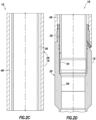
FIGS. 2A-D are enlarged scale cross-sectional views of successive axial sections of a circulation control valve, which may be used in the well system and method ofFIG. 1 but does not fall within the scope of the claimed invention, the valve being depicted in a run-in closed configuration; -
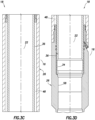
FIGS. 3A-D are cross-sectional views of successive axial sections of the valve ofFIGS. 2A-D , the valve being depicted in an open circulating configuration; -
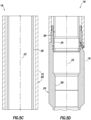
FIGS. 4A-D are cross-sectional views of successive axial sections of the valve ofFIGS. 2A-D , the valve being depicted in a subsequent closed configuration; -
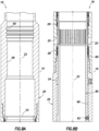
FIGS. 5A-D are cross-sectional views of successive axial sections of the valve ofFIGS. 2A-D , the valve being depicted in another closed configuration; -
FIG. 6 is a further enlarged scale elevational view of a displacement limiting device of the valve ofFIGS. 2A-D ; -
FIGS. 7A-D are cross-sectional views of successive axial sections of another construction of the circulation control valve which may be used in the well system and method ofFIG. 1 but does not fall within the scope of the claimed invention, the valve being depicted in a run-in closed configuration; -
FIGS. 8A-D are cross-sectional views of successive axial sections of the valve ofFIGS. 7A-D , the valve being depicted in an open circulating configuration; -
FIGS. 9A-D are cross-sectional views of successive axial sections of the valve ofFIGS. 7A-D , the valve being depicted in a subsequent closed configuration; -
FIGS. 10A-C are cross-sectional views of successive axial sections of another construction of the circulation control valve which may be used in the well system and method ofFIG. 1 but does not fall within the scope of the claimed invention, the valve being depicted in a run-in closed configuration; -
FIGS. 11A-C are cross-sectional views of successive axial sections of the valve ofFIGS. 10A-C , the valve being depicted in an open circulating configuration; -
FIGS. 12A-C are cross-sectional views of successive axial sections of the valve ofFIGS. 10A-C , the valve being depicted in a subsequent closed configuration; -
FIGS. 13A-C are cross-sectional views of successive axial sections of another construction of the circulation control valve which may be used in the well system and method ofFIG. 1 but does not fall within the scope of the claimed invention, the valve being depicted in a run-in closed configuration; -
FIG. 14 is a cross-sectional view of the valve ofFIGS.13A-C , taken along line 14-14 ofFIG. 13B ; -
FIGS. 15A-C are cross-sectional views of successive axial sections of the valve ofFIGS. 13A-C , the valve being depicted in an open circulating configuration; -
FIG. 16 is a cross-sectional view of the valve ofFIGS.15A-C , taken along line 16-16 ofFIG. 15B ; -
FIGS. 17A-C are cross-sectional views of successive axial sections of the valve ofFIGS. 13A-C , the valve being depicted in a subsequent closed configuration; -
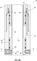
FIG. 18 is a cross-sectional view of another construction of the valve, with the valve being depicted in a pressure-opened configuration; -
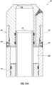
FIG. 19 is a cross-sectional view of the valve ofFIG. 18 , with the valve being depicted in a pressure-closed configuration; -
FIG. 20 is a cross-sectional view of the valve ofFIGS. 18 &19 , with the valve being depicted in a mechanically shifted-open configuration; and -
FIG. 21 is a cross-sectional view of the valve ofFIGS. 18-20 , with the valve being depicted in a mechanically shifted-closed configuration. - It is to be understood that the various examples described herein may be utilized in various orientations, such as inclined, inverted, horizontal, vertical, etc., and in various configurations, without departing from the principles of the present disclosure. The examples are useful applications of the principles of this disclosure, which is not limited to any specific details of these examples.
- In the following description of the representative examples, directional terms, such as "above", "below", "upper", "lower", etc., are used for convenience in referring to the accompanying drawings. In general, "above", "upper", "upward" and similar terms refer to a direction toward the earth's surface along a wellbore, and "below", "lower", "downward" and similar terms refer to a direction away from the earth's surface along the wellbore.
- Representatively illustrated in
FIG. 1 is a well system and associatedmethod 10 which embody principles of the present disclosure. In thewell system 10, atubular string 12 is installed in awellbore 14, thereby forming an annulus 16 exterior to the tubular string. Thewellbore 14 could be lined with casing or liner, in which case theannulus 16 may be formed between thetubular string 12 and the casing or liner. - The
tubular string 12 could be a production tubing string which is cemented in thewellbore 14 to form what is known to those skilled in the art as a "cemented completion." This term describes a well completion in which production tubing is cemented in an otherwise uncased wellbore. However, it should be clearly understood that the present disclosure is not limited in any way to use in cemented completions, or to any other details of thewell system 10 or method described herein. - If the
tubular string 12 is cemented in thewellbore 14, it may be desirable to circulate cement out of an upper portion of theannulus 16. For this purpose, acirculation control valve 18 is provided in thewell system 10. - Near the conclusion of the cementing operation,
openings 20 in thevalve 18 are opened to permit circulation flow between theannulus 16 and aninterior flow passage 22 of thetubular string 12. After circulation flow is no longer desired, theopenings 20 in thevalve 18 are closed. - Referring additionally now to
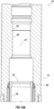
FIGS. 2A-D , thevalve 18 is representatively illustrated at an enlarged scale and in greater detail. Thevalve 18 may be used in thewell system 10 and associated method as described above but does not fall within the scope of the claimed invention. - As depicted in
FIGS. 2A-D , thevalve 18 is in a run-in closed configuration in which flow through theopenings 20 between theflow passage 22 and theannulus 16 is prevented. When used in a cemented completion, this configuration of thevalve 18 would be used when thetubular string 12 is installed in thewellbore 14, and when cement is flowed into theannulus 16. When used in a staged cementing operation, thevalve 18 may be open when cement is flowed into theannulus 16. - A generally
tubular closure device 24 in the form of a sleeve is reciprocably displaceable within anouter housing assembly 26 of thevalve 18 in order to selectively permit and prevent fluid flow through theopenings 20. Theclosure device 24 carries flexible orresilient seals 28 thereon for sealing across theopenings 20, but in an important feature of the example ofFIGS. 2A-D , a metal-to-metal seal 30 is also provided to ensure against leakage in the event that theother seals 28 fail. - Furthermore, another
internal sleeve 36 andadditional seals 32 are provided, so that theopenings 20 can be sealed off positively. Thesleeve 36 can be displaced from within theflow passage 22, for example, using a conventional shifting tool engaged with aninternal shifting profile 34 in the sleeve. Thesleeve 36 is depicted in its closed position inFIGS. 5A-D . - The metal-to-
metal seal 30 is enhanced by operation of asealing device 40 which includes an arrangement ofpistons biasing device 44. In an important feature of the sealingdevice 40, at least one of thepistons metal seal 30 whether pressure in theflow passage 22 is greater than pressure in theannulus 16, or pressure in the annulus is greater than pressure in the flow passage. - This feature of the sealing
device 40 is due to a unique configuration of differential piston areas on thepistons pistons FIG. 2B , when pressure in theflow passage 22 is greater than pressure in theannulus 16, the pistons will be biased downwardly as viewed in the drawing, thereby applying a downwardly biasing force to the metal-to-metal seal 30. - When pressure in the
annulus 16 is greater than pressure in theflow passage 22, thepiston 38 will be biased upwardly as viewed in the drawing, but thepiston 42 will be biased downwardly, thereby again applying a downwardly biasing force to the metal-to-metal seal 30. Thus, no matter the direction of the pressure differential between theflow passage 22 and theannulus 16, the metal-to-metal seal 30 between thepiston 42 and theclosure device 24 is always enhanced by the sealingdevice 40. - The biasing
device 44 is used to exert an initial biasing force to the metal-to-metal seal 30. Asnap ring 46 installed in thehousing assembly 26 limits upward displacement of theclosure device 24 and limits downward displacement of thepistons - The
closure device 24 is biased upwardly by means of a pressurizedinternal chamber 48. Thechamber 48 could, for example, contain nitrogen or another inert gas at a pressure exceeding any hydrostatic pressure expected to be experienced at thevalve 18 in thewellbore 14. Other compressible fluids, such as silicone, etc., could be used in thechamber 48, if desired. - The
seals closure device 24 close off an upper end of thechamber 48. The upper end of theclosure device 24 is exposed to pressure in theflow passage 22. Thus, if pressure in theflow passage 22 is increased sufficiently, so that it is greater than the pressure in thechamber 48, theclosure device 24 will be biased to displace downwardly. - Displacement of the
closure device 24 relative to thehousing assembly 26 is limited by means of adisplacement limiting device 54. Thedevice 54 includes one or more pin or lug(s) 50 secured to thehousing assembly 26, and asleeve 56 rotationally attached to theclosure device 24, with the sleeve having one or more profile(s) 52 formed thereon for engagement by the lug. - Referring additionally now to
FIGS. 3A-D , thevalve 18 is representatively illustrated in a configuration in which pressure in theflow passage 22 has been increased to a level greater than the pressure in thechamber 48. As a result, theclosure device 24 has displaced downwardly relative to thehousing assembly 26, and fluid flow through theopenings 20 is now permitted. - Subsequent release of the increased pressure in the
flow passage 22 allows thelug 50 in thehousing assembly 26 to engage a recessedportion 52a of theprofile 52. This functions to secure theclosure device 24 in its open position, without the need to maintain the increased pressure in theflow passage 22. - An enlarged scale view of the
sleeve 56 andprofile 52 thereon is representatively illustrated inFIG. 6 . In this view it may be seen that thelug 50 can displace relative to theprofile 52 betweenseveral portions 52a-f of the profile. - Initially, in the run-in configuration of
FIGS. 2A-D , thelug 50 is engaged in a generally straight longitudinally extendingprofile portion 52b. When pressure in theflow passage 22 has been increased so that it is greater than pressure in thechamber 48, thelug 50 will be engaged inprofile portion 52d (with thevalve 18 being open). Subsequent release of the increased pressure in theflow passage 22 will cause thelug 50 to engageprofile portion 52a, thereby maintaining thevalve 18 in its open configuration. - Another application of increased pressure to the
flow passage 22 greater than pressure in thechamber 48 will cause thelug 50 to engageprofile portion 52e (with thevalve 18 still being open). Subsequent release of the increased pressure in theflow passage 22 will cause thelug 50 to engageprofile portion 52c, with theclosure device 24 correspondingly displacing to its closed position (as depicted inFIGS. 4A-D ). - Further increases and decreases in pressure in the
flow passage 22 will not result in further opening and closing of thevalve 18. Instead, thelug 50 will move back and forth betweenprofile portions 52c & f. This is beneficial in cemented completions, in which further circulation through thevalve 18 is not desired. However, further openings and closings of thevalve 18 could be provided, for example, by making theprofile 52 continuous about thesleeve 56 in the manner of a conventional continuous J-slot, if desired. - Referring additionally now to
FIGS. 4A-D , thevalve 18 is representatively illustrated after the second application of increased pressure to theflow passage 22, and then release of the increased pressure as described above. Thevalve 18 is now in a closed configuration, in which fluid communication between theflow passage 22 andannulus 16 via theopenings 20 is prevented by theclosure device 24. - Note that the
lug 50 is now engaged with theprofile portion 52f as depicted inFIG. 4B . This demonstrates that further increases in pressure in theflow passage 22 do not cause thevalve 18 to open, since thedevice 54 limits further downward displacement of theclosure device 24. - However, it will be readily appreciated that the
profile 52 could be otherwise configured, for example, as a continuous J-slot type profile, to allow multiple openings and closings of thevalve 18. Thus, theclosure device 24 can be repeatedly displaced upward and downward to close and open thevalve 18 in response to multiple applications and releases of pressure in theflow passage 22, if theprofile 52 is appropriately configured. - Referring additionally now to
FIGS. 5A-D , thevalve 18 is representatively illustrated in a closed configuration in which theinternal sleeve 36 has been displaced upwardly, so that it now blocks flow through theopenings 20 between theannulus 16 and flowpassage 22. Displacement of thesleeve 36 may be accomplished by any of a variety of means, but preferably a conventional wireline or tubing conveyed shifting tool is used. - The
sleeve 36 may be displaced as a contingency operation, in the event that one or more of theseals closure device 24 is otherwise not operable to prevent fluid communication between theflow passage 22 and theannulus 16 via theopenings 20. Seal bores 58 and a latchingprofile 60 may also (or alternatively) be provided for installation of a conventional packoff sleeve, if desired. - Referring additionally now to
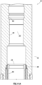
FIGS. 7A-D , an alternate configuration of thecirculation control valve 18 is representatively illustrated, which does not fall within the scope of the claimed invention. The configuration ofFIGS.7A-D is similar in many respects to the configuration described above, most notably in that both configurations open in response to application of a pressure increase to theflow passage 22, and then close following application of a subsequent pressure increase to the flow passage. - However, the configuration of
FIGS. 7A-D utilizesvalve devices closure device 24. Thevalve devices valve devices internal chambers - A radially enlarged
piston 70 on theclosure device 24 is exposed to thechamber 66 on its upper side, and a lower side of the piston is exposed to anotherchamber 72. Another radially enlargedpiston 74 on asleeve 78 positioned below theclosure device 24 is exposed to thechamber 68 on its lower side, and an upper side of the piston is exposed to anotherchamber 76. - All of the
chambers - The
closure device 24 is initially maintained in its closed position by one or more shear pins 80. However, when pressure in theflow passage 22 is increased to achieve a predetermined pressure differential (from the flow passage to the chamber 66), thevalve device 62 will open and admit the well pressure into thechamber 66. The resulting pressure differential across the piston 70 (between thechambers 66, 72) will cause a downwardly directed biasing force to be exerted on theclosure device 24, thereby shearing the shear pins 80 and downwardly displacing the closure device. - Referring additionally now to
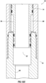
FIGS. 8A-D , thevalve 18 is representatively illustrated after theclosure device 24 has displaced downwardly following opening of thevalve device 62. Fluid communication between theflow passage 22 and theannulus 16 via theopenings 20 is now permitted. - When it is desired to close the
valve 18, pressure in theflow passage 22 andannulus 16 may be increased to a predetermined pressure differential (from the annulus to the chamber 68) to open thevalve device 64. Note that thevalve device 64 is physically exposed to theannulus 16, rather than to theflow passage 22, and so the valve device is not in fluid communication with the flow passage until theclosure device 24 is displaced downwardly to open thevalve 18. As a result, it is not necessary for the predetermined pressure differential used for opening thevalve device 64 to be greater than the predetermined pressure differential used for opening thevalve device 62. - When the
valve device 64 opens, well pressure will be admitted into thechamber 68, and the resulting pressure differential (between thechambers 68, 76) across thepiston 74 will cause an upwardly directed biasing force to be exerted on thesleeve 78. Thesleeve 78 will displace upwardly and contact theclosure device 24. Since thepiston 74 has a greater differential piston area than that of thepiston 70, the upwardly directed biasing force due to the pressure differential across thepiston 74 will exceed the downwardly directed biasing force due to the pressure differential across thepiston 70, and theclosure device 24 will displace upwardly as a result. - Referring additionally now to
FIGS. 9A-D , thevalve 18 is representatively illustrated after theclosure device 24 has displaced upwardly following opening of thevalve device 64. Theclosure device 24 again prevents fluid communication between theflow passage 22 and theannulus 16 via theopenings 20. - A
snap ring 82 carried on thesleeve 78 now engages aninternal profile 84 formed in thehousing assembly 26 to prevent subsequent downward displacement of theclosure device 24. Note that aninternal sleeve 36 and/or latchingprofile 60 and seal bores 58 may be provided for ensuring that theopenings 20 can be sealed off as a contingency measure, or as a matter of course when operation of thevalve 18 is no longer needed. - However, in the alternate configuration of
FIGS. 7A-9D , theclosure device 24 is itself provided with a shiftingprofile 86 to allow the closure device to be displaced to its closed position from the interior of the flow passage 22 (such as, using a conventional shifting tool), in the event that the closure device cannot be otherwise displaced upwardly (such as, due to seal leakage or valve device malfunction, etc.). - Referring additionally now to
FIGS. 10A-B , another construction of thecirculation control valve 18, which falls outside the scope of the claimed invention, is representatively illustrated in its run-in closed configuration. This example of thevalve 18 is somewhat similar to the valve ofFIGS. 7A-9D , in that avalve device 62 is opened in order to open thevalve 18, and another valve device 64 (seeFIG. 12B ) is opened in order to close thevalve 18. - However, in the example of
FIGS. 10A-C , multiple relatively largediameter valve devices 62 are opened, which themselves provide fluid communication between theflow passage 22 and theannulus 16, without displacing theclosure device 24. Instead, thevalve devices 62 are opened in response to a predetermined differential pressure from theflow passage 22 to theannulus 16, and thereafter fluid communication is permitted through the valve devices between the flow passage and the annulus. - In
FIGS. 11A-C , thevalve 18 is representatively illustrated after thevalve devices 62 have been opened. Note that this cross-section of thevalve 18 is rotated 90 degrees about the longitudinal axis of the valve, so that various other features of the valve (such as the valve device 64) may be clearly seen. - The
closure device 24 is maintained in the same position as it was inFIGS. 10A-C by shear pins 80. Note also, that theopen valve devices 62 provide a relatively large flow area for flowing fluid between thepassage 22 and theannulus 16. - In
FIGS. 12A-C , thevalve 18 is shown after pressure has been increased to thereby open thevalve device 64. As with thevalve 18 ofFIGS. 9A-C , this opening of thevalve device 64 causes thesleeve 78 to displace upward, thereby shearing the shear pins 80, and displacing theclosure device 24 upward to close off theopenings 20. Also, since thevalve device 64 is exposed to theannulus 16 and not to thepassage 22 prior to the opening of thevalve devices 62, thevalve device 64 is unaffected by pressure in thepassage 22 until after thevalve devices 62 are opened. - A slip-type
ratchet locking device 88 maintains theclosure device 24 in its closed position as depicted inFIG. 12A . At any time it is desired to close thevalve 18, a conventional shifting tool (not shown) can be engaged with theprofile 86 and upward force thereby applied to shear the shear pins 80 and displace theclosure device 24 upward. - Referring additionally now to
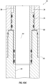
FIGS. 13A-C , another construction of thecirculation control valve 18, which does not fall within the scope of the claimed invention, is representatively illustrated in its closed run-in configuration. This example of thevalve 18 is similar in many respects to the example ofFIGS. 7A-9C , but theclosure device 24 in the example ofFIGS. 13A-C displaces upwardly to open the valve (uncovering the openings 20), and thesleeve 74 displaces downwardly to shift the closure device back downwardly to close the valve. Otherwise, the operation of thevalve 18 is fundamentally the same. - In
FIG. 14 , the arrangement ofvalve devices 62 about theclosure device 24 may be seen in more detail. Thechambers passage 22 exceeds a predetermined value, thevalve devices 62 open, thereby exposing thechamber 66 to the increased pressure. - In
FIGS. 15A-C , thevalve 18 is representatively illustrated in its open configuration, after thevalve devices 62 have opened. The resulting pressure differential across thepiston 70 causes theclosure device 24 to displace upwardly, thereby uncovering theopenings 20. - In
FIG. 16 , it may be seen that thechamber 76 extends to a fill/pressure relief port 90. Pressure in thechamber 76 is initially relatively low (such as atmospheric pressure). - In
FIGS. 17A-C , the valve is shown in its closed configuration after thevalve devices 64 have been opened. Thevalve devices 64 are opened by increasing pressure in theannulus 16 to a predetermined level (i.e., to achieve a predetermined pressure differential from the annulus to the chamber 68), either by pressurizing the annulus or the passage 22 (since they are in communication via the openings 20) . - The
sleeve 78 has displaced downward due to the pressure differential from thechamber 68 to thechamber 76, shearing shear pins 92. This downward displacement of thesleeve 78 also causes theclosure device 24 to displace downward (since the differential piston area on thepiston 74 is greater than the differential piston area on the piston 70). - Referring additionally now to
FIG. 18 , another construction of thecirculation control valve 18 is representatively illustrated. Thevalve 18 ofFIG. 18 is similar in many respects to the valves ofFIGS. 10A-12C andFIGS. 13A-17C , in that it may be opened and then closed by application of pressure to the valve. However, thevalve 18 ofFIG. 18 may subsequently (after pressure operation) be opened and closed mechanically (e.g., by use of a mechanical shifting tool). - As depicted in
FIG. 18 , thevalve devices 62 have already been opened in response to application of a predetermined pressure differential from thepassage 22 to theannulus 16. Relatively unrestricted fluid communication is now permitted between thepassage 22 and theannulus 16 via theopenings 20 in thehousing assembly 26 andopenings 96 in theclosure device 24. Engagement between anannular recess 102 formed in thehousing assembly 26 andprojections 98 onresilient collets 100 formed on theclosure device 24 prevents the closure device from inadvertently displacing during run-in and opening of thevalve devices 62. - In order to pressure-close the
valve 18, a predetermined pressure may be applied to thevalve device 64 to open the valve device and thereby permit fluid communication between theannulus 16 and thechamber 68 below thepiston 74. With thevalve devices 62 open, pressure is the same in thepassage 22 and theannulus 16, but prior to opening thevalve devices 62, thevalve device 64 is preferably isolated from pressure in thepassage 22, and so it is not necessary for the pressure used to open thevalve devices 62 to be greater than pressure used to open thevalve device 64. - Referring additionally now to
FIG. 19 , thevalve 18 is representatively illustrated in a closed configuration. Thevalve device 64 has been opened by applying pressure to theannulus 16 and/orpassage 22, whereby the pressure is communicated to thechamber 68 and thepiston 74 is biased upward due to the pressure differential from thechamber 68 to thechamber 76. - The
openings 20 are now closed off by theclosure device 24. Theprojections 98 on thecollets 100 now engage anotherrecess 104 in thehousing assembly 26, thereby preventing inadvertent downward displacement of theclosure device 24. - Note that the
piston 74 is in the form of a sleeve which encircles theclosure device 24. When thepiston 74 is biased upward due to the pressure differential from thechamber 68 to thechamber 76, the piston pushes against aring 106 which is releasably secured to theclosure device 24 by engagement of multiple lugs 108 (only one of which is visible inFIGS. 18-21 ) in arecess 110 formed on the closure device. - When the
closure device 24 is in its downwardly disposed open position (as depicted inFIG. 18 ), thelugs 108 are maintained in engagement with therecess 110 by an innercylindrical wall 112 of thehousing assembly 26. Thewall 112 corresponds to an outer diameter of thechamber 68 which is sealingly engaged by thepiston 74. - However, when the closure device is in its upwardly disposed closed position (as depicted in
FIG. 19 ), thelugs 108 are no longer retained in engagement with therecess 110, since the lugs are now able to displace radially outward into a radiallyenlarged recess 114 formed in thehousing assembly 26. At this point, theclosure device 24 can be displaced independently of thepiston 74,ring 106 and lugs 108. - Referring additionally now to
FIG. 20 , thevalve 18 is representatively illustrated in a mechanically shifted-open configuration. A shiftingtool 116 has been conveyed into thevalve 18 via thepassage 22 and shiftingdogs 118 on the tool have engaged aprofile 120 formed in theclosure device 24 to thereby apply a downwardly directed force to the closure device, in order to displace the closure device downwardly to its open position. - Thus, the
valve 18 can be opened mechanically after it has been closed by pressure. Theprojections 98 on thecollets 100 again engage therecess 102 to prevent inadvertent displacement of theclosure device 24. - Referring additionally now to
FIG. 21 , thevalve 18 is representatively illustrated in a mechanically shifted-closed configuration. A shifting tool (such as the shiftingtool 116 described above and depicted inFIG. 20 ) may be used to engage theprofile 86 and displace theclosure device 24 upward, so that the closure device again prevents fluid communication between thepassage 22 and theannulus 16 via theopenings 20. - The
closure device 24 may be mechanically displaced between its open and closed positions as depicted inFIGS. 20 and21 any number of times. Theprojections 98 will alternately engage therecesses closure device 24 is displaced to its respective open and closed positions. Note that, in each of its mechanically operated displacements, thepiston 74 does not displace with the closure device 24 (due to thelugs 108 no longer being retained in the recess 110), but instead is maintained in its upwardly disposed position by the pressure differential from thechamber 68 to thechamber 76. - It may now be fully appreciated that the above description of the
circulation control valve 18 configurations provides significant improvements in the art. Thevalve 18 is capable of reliably and conveniently providing a large flow area for circulation between theflow passage 22 and theannulus 16, and is further capable of reliably and conveniently preventing fluid communication between the flow passage and annulus when desired. Thevalve 18 ofFIGS. 18-21 may further be mechanically opened and closed after being opened and closed by pressure.
Claims (7)
- A method of controlling flow between an interior flow passage (22) of a tubular string (12) and an annulus (16) external to the tubular string (12) in a subterranean well, the method comprising the steps of:applying a fluid pressure differential across a piston (74) of a valve (18) interconnected in the tubular string (12), thereby displacing the piston (74) and a closure device (24) of the valve (18) to prevent fluid communication between the interior flow passage (22) and the annulus (16) via at least one opening (20) through a sidewall of the valve (18); andthen displacing the closure device (24) relative to the piston (74), thereby allowing fluid communication between the flow passage (22) and the annulus (16) via the at least one opening (20).
- The method of claim 1, further comprising, prior to the prevention of fluid communication through the at least one opening (20), permitting fluid communication through the at least one opening (20).
- The method of claim 2, wherein the permission of fluid communication prior to the prevention of fluid communication through the at least one opening (20) is in response to an application of pressure to the valve (18).
- The method of claim 1, further comprising, after the displacement of the closure device relative to the piston (74) to allow fluid communication between the interior flow passage (22) and the annulus (16) via the at least one opening (20), displacing the closure device (24) relative to the piston (74), thereby preventing fluid communication through the at least one opening (20) between the interior flow passage (22) and the annulus (16).
- The method of claim 1, wherein the displacement of the closure device (24) relative to the piston (74) to allow fluid communication between the flow passage (22) and the annulus (16) via the at least one opening (20) further comprises engaging a shifting tool with a profile (86) in the valve (18).
- The method of claim 1, further comprising, prior to the application of the fluid pressure differential, applying a first increased pressure to the interior flow passage (22) while fluid communication through the at least one opening (20) between the interior flow passage (22) and the annulus (16) is prevented, thereby opening at least one first valve device (62) and permitting fluid communication through the at least one first valve device (62), thereby permitting fluid communication through the at least one opening (20) between the interior flow passage (22) and the annulus (16).
- The method of claim 6, wherein the application of the fluid pressure differential across the piston (74) comprises applying a second increased pressure to the interior flow passage (22) and the annulus (16) while fluid communication through the at least one opening (20) is permitted, thereby opening at least one second valve device (64) and permitting fluid communication through the at least one second valve device (64).
Applications Claiming Priority (3)
| Application Number | Priority Date | Filing Date | Title |
|---|---|---|---|
| US12/398,151 US8833468B2 (en) | 2009-03-04 | 2009-03-04 | Circulation control valve and associated method |
| PCT/US2010/025511 WO2010101775A2 (en) | 2009-03-04 | 2010-02-26 | Circulation control valve and associated method |
| EP10749123.5A EP2404027B1 (en) | 2009-03-04 | 2010-02-26 | Circulation control valve and associated method |
Related Parent Applications (2)
| Application Number | Title | Priority Date | Filing Date |
|---|---|---|---|
| EP10749123.5A Division-Into EP2404027B1 (en) | 2009-03-04 | 2010-02-26 | Circulation control valve and associated method |
| EP10749123.5A Division EP2404027B1 (en) | 2009-03-04 | 2010-02-26 | Circulation control valve and associated method |
Publications (2)
| Publication Number | Publication Date |
|---|---|
| EP3757347A1 EP3757347A1 (en) | 2020-12-30 |
| EP3757347B1 true EP3757347B1 (en) | 2023-11-15 |
Family
ID=42677204
Family Applications (2)
| Application Number | Title | Priority Date | Filing Date |
|---|---|---|---|
| EP20191449.6A Active EP3757347B1 (en) | 2009-03-04 | 2010-02-26 | Circulation control valve and associated method |
| EP10749123.5A Active EP2404027B1 (en) | 2009-03-04 | 2010-02-26 | Circulation control valve and associated method |
Family Applications After (1)
| Application Number | Title | Priority Date | Filing Date |
|---|---|---|---|
| EP10749123.5A Active EP2404027B1 (en) | 2009-03-04 | 2010-02-26 | Circulation control valve and associated method |
Country Status (8)
| Country | Link |
|---|---|
| US (1) | US8833468B2 (en) |
| EP (2) | EP3757347B1 (en) |
| CN (1) | CN102325957B (en) |
| BR (1) | BRPI1005988B1 (en) |
| CA (1) | CA2752521C (en) |
| DK (1) | DK3757347T3 (en) |
| SG (1) | SG174210A1 (en) |
| WO (1) | WO2010101775A2 (en) |
Families Citing this family (14)
| Publication number | Priority date | Publication date | Assignee | Title |
|---|---|---|---|---|
| AU2014203078B2 (en) * | 2010-01-06 | 2016-05-19 | Weatherford Technology Holdings, Llc | Rotating continuous flow sub |
| WO2013110180A1 (en) * | 2012-01-24 | 2013-08-01 | Cramer David S | Downhole valve and latching mechanism |
| US9447654B2 (en) * | 2012-04-26 | 2016-09-20 | Halliburton Energy Services, Inc. | Downhole circulating valve having a seal plug and method for operating same |
| BR112015000887A2 (en) * | 2012-08-29 | 2017-06-27 | Halliburton Energy Services Inc | glove unit, and method of driving a glove unit installed on the production pipe ". |
| US10907445B2 (en) * | 2013-02-25 | 2021-02-02 | Halliburton Energy Services, Inc. | Autofill and circulation assembly and method of using the same |
| NO338693B1 (en) * | 2013-09-23 | 2016-10-03 | Trican Completion Solutions As | Pressure-activated valve |
| CA2938179C (en) | 2014-02-04 | 2023-03-14 | Rapid Design Group Inc. | Pressure activated completion tools and methods of use |
| WO2016161306A1 (en) * | 2015-04-01 | 2016-10-06 | Weatherford Technology Holdings, Llc | Metal-to-metal sealing valve with managed flow erosion across sealing member |
| CA3020992A1 (en) | 2015-10-20 | 2017-04-27 | Modern Wellbore Solutions Ltd. | Apparatus and methods for cementing of wellbores |
| GB201600468D0 (en) * | 2016-01-11 | 2016-02-24 | Paradigm Flow Services Ltd | Fluid discharge apparatus and method of use |
| US10233725B2 (en) * | 2016-03-04 | 2019-03-19 | Baker Hughes, A Ge Company, Llc | Downhole system having isolation flow valve and method |
| CN106761545A (en) * | 2017-02-28 | 2017-05-31 | 中国石油天然气股份有限公司 | A kind of oil gas well cementing operation tubing string and cementing method |
| NO343864B1 (en) | 2018-04-25 | 2019-06-24 | Interwell Norway As | Well tool device for opening and closing a fluid bore in a well |
| WO2019218073A1 (en) * | 2018-05-16 | 2019-11-21 | 1966109 Alberta Ltd. | Well string staging tool |
Family Cites Families (33)
| Publication number | Priority date | Publication date | Assignee | Title |
|---|---|---|---|---|
| US3410346A (en) * | 1966-06-03 | 1968-11-12 | Henry U Garrett | Well apparatus |
| US3823773A (en) * | 1972-10-30 | 1974-07-16 | Schlumberger Technology Corp | Pressure controlled drill stem tester with reversing valve |
| US4403659A (en) * | 1981-04-13 | 1983-09-13 | Schlumberger Technology Corporation | Pressure controlled reversing valve |
| US4429747A (en) * | 1981-09-01 | 1984-02-07 | Otis Engineering Corporation | Well tool |
| US4513764A (en) * | 1983-05-27 | 1985-04-30 | Otis Engineering Corporation | Valve |
| US4657082A (en) * | 1985-11-12 | 1987-04-14 | Halliburton Company | Circulation valve and method for operating the same |
| US4889199A (en) * | 1987-05-27 | 1989-12-26 | Lee Paul B | Downhole valve for use when drilling an oil or gas well |
| FR2626647B1 (en) * | 1988-01-29 | 1990-07-20 | Inst Francais Du Petrole | SLIDING SLEEVE VALVE FOR PRODUCING WELLBORE IN THE GROUND |
| US5020592A (en) * | 1988-12-09 | 1991-06-04 | Dowell Schlumberger Incorporated | Tool for treating subterranean wells |
| US4913231A (en) * | 1988-12-09 | 1990-04-03 | Dowell Schlumberger | Tool for treating subterranean wells |
| US5529126A (en) * | 1990-10-03 | 1996-06-25 | Expro North Sea Limited | Valve control apparatus |
| US5819853A (en) * | 1995-08-08 | 1998-10-13 | Schlumberger Technology Corporation | Rupture disc operated valves for use in drill stem testing |
| US5609178A (en) * | 1995-09-28 | 1997-03-11 | Baker Hughes Incorporated | Pressure-actuated valve and method |
| WO1997036089A1 (en) | 1996-03-22 | 1997-10-02 | Smith International, Inc. | Hydraulic sliding side-door sleeve |
| GB2314106B (en) * | 1996-06-11 | 2000-06-14 | Red Baron | Multi-cycle circulating sub |
| AU8385498A (en) * | 1997-07-10 | 1999-02-08 | Camco International, Inc. | Single-phase annulus-operated sliding sleeve |
| US6102126A (en) * | 1998-06-03 | 2000-08-15 | Schlumberger Technology Corporation | Pressure-actuated circulation valve |
| US6397949B1 (en) * | 1998-08-21 | 2002-06-04 | Osca, Inc. | Method and apparatus for production using a pressure actuated circulating valve |
| US6439306B1 (en) * | 1999-02-19 | 2002-08-27 | Schlumberger Technology Corporation | Actuation of downhole devices |
| US6464008B1 (en) * | 2001-04-25 | 2002-10-15 | Baker Hughes Incorporated | Well completion method and apparatus |
| CA2445870C (en) * | 2001-04-30 | 2009-04-07 | Weatherford/Lamb, Inc. | Automatic tubing filler |
| GB2391566B (en) * | 2002-07-31 | 2006-01-04 | Schlumberger Holdings | Multiple interventionless actuated downhole valve and method |
| CA2500163C (en) * | 2002-10-02 | 2009-01-27 | Baker Hughes Incorporated | Cementing through a side pocket mandrel |
| US7063152B2 (en) * | 2003-10-01 | 2006-06-20 | Baker Hughes Incorporated | Model HCCV hydrostatic closed circulation valve |
| CN2585971Y (en) | 2002-12-16 | 2003-11-12 | 韩明胜 | Underground sliding bush switching device of well killing free operation |
| US7367393B2 (en) * | 2004-06-01 | 2008-05-06 | Baker Hughes Incorporated | Pressure monitoring of control lines for tool position feedback |
| US7258323B2 (en) * | 2005-06-15 | 2007-08-21 | Schlumberger Technology Corporation | Variable radial flow rate control system |
| US7552773B2 (en) * | 2005-08-08 | 2009-06-30 | Halliburton Energy Services, Inc. | Multicycle hydraulic control valve |
| US7520333B2 (en) * | 2005-11-11 | 2009-04-21 | Bj Services Company | Hydraulic sleeve valve with position indication, alignment, and bypass |
| CN200982181Y (en) | 2006-12-06 | 2007-11-28 | 吐哈石油勘探开发指挥部钻采工艺研究院 | Circulation sliding sleeve for oil gas field |
| DK2189622T3 (en) * | 2007-01-25 | 2019-02-04 | Welldynamics Inc | Casing valve system for selective borehole stimulation and control |
| US7971646B2 (en) * | 2007-08-16 | 2011-07-05 | Baker Hughes Incorporated | Multi-position valve for fracturing and sand control and associated completion methods |
| US7866402B2 (en) * | 2007-10-11 | 2011-01-11 | Halliburton Energy Services, Inc. | Circulation control valve and associated method |
-
2009
- 2009-03-04 US US12/398,151 patent/US8833468B2/en active Active
-
2010
- 2010-02-26 BR BRPI1005988 patent/BRPI1005988B1/en active IP Right Grant
- 2010-02-26 WO PCT/US2010/025511 patent/WO2010101775A2/en active Application Filing
- 2010-02-26 CN CN201080008950.9A patent/CN102325957B/en active Active
- 2010-02-26 EP EP20191449.6A patent/EP3757347B1/en active Active
- 2010-02-26 DK DK20191449.6T patent/DK3757347T3/en active
- 2010-02-26 CA CA2752521A patent/CA2752521C/en not_active Expired - Fee Related
- 2010-02-26 EP EP10749123.5A patent/EP2404027B1/en active Active
- 2010-02-26 SG SG2011063161A patent/SG174210A1/en unknown
Also Published As
| Publication number | Publication date |
|---|---|
| CN102325957B (en) | 2015-12-09 |
| EP2404027B1 (en) | 2020-10-07 |
| SG174210A1 (en) | 2011-10-28 |
| BRPI1005988B1 (en) | 2019-11-26 |
| CA2752521C (en) | 2016-03-29 |
| BRPI1005988A2 (en) | 2016-02-10 |
| US8833468B2 (en) | 2014-09-16 |
| EP3757347A1 (en) | 2020-12-30 |
| EP2404027A2 (en) | 2012-01-11 |
| CA2752521A1 (en) | 2010-09-10 |
| US20100224371A1 (en) | 2010-09-09 |
| WO2010101775A3 (en) | 2010-12-29 |
| EP2404027A4 (en) | 2017-11-01 |
| CN102325957A (en) | 2012-01-18 |
| DK3757347T3 (en) | 2024-01-02 |
| WO2010101775A2 (en) | 2010-09-10 |
Similar Documents
| Publication | Publication Date | Title |
|---|---|---|
| EP3757347B1 (en) | Circulation control valve and associated method | |
| AU2008310966B2 (en) | Circulation control valve and associated method | |
| DK2189622T3 (en) | Casing valve system for selective borehole stimulation and control | |
| US7303020B2 (en) | Interventionless oil tool actuator with floating piston and method of use | |
| US5526878A (en) | Stage cementer with integral inflation packer | |
| US6997252B2 (en) | Hydraulic setting tool for packers | |
| US6109357A (en) | Control line actuation of multiple downhole components | |
| US20060169464A1 (en) | Positioning tool with valved fluid diversion path | |
| US3874634A (en) | Well safety valve system | |
| DK2699761T3 (en) | Ball valve safety plug | |
| AU2010284836B2 (en) | Internal retention mechanism | |
| US9422790B2 (en) | Safety valve with lockout capability and methods of use | |
| NO20160716A1 (en) | Locking mechanism for downhole positioning of sleeves | |
| AU754854B2 (en) | Flow control apparatus with specific latching means for use in a subterranean well and associated methods | |
| AU2013273636C1 (en) | Casing valves system for selective well stimulation and control |
Legal Events
| Date | Code | Title | Description |
|---|---|---|---|
| PUAI | Public reference made under article 153(3) epc to a published international application that has entered the european phase |
Free format text: ORIGINAL CODE: 0009012 |
|
| STAA | Information on the status of an ep patent application or granted ep patent |
Free format text: STATUS: THE APPLICATION HAS BEEN PUBLISHED |
|
| AC | Divisional application: reference to earlier application |
Ref document number: 2404027 Country of ref document: EP Kind code of ref document: P |
|
| AK | Designated contracting states |
Kind code of ref document: A1 Designated state(s): AT BE BG CH CY CZ DE DK EE ES FI FR GB GR HR HU IE IS IT LI LT LU LV MC MK MT NL NO PL PT RO SE SI SK SM TR |
|
| STAA | Information on the status of an ep patent application or granted ep patent |
Free format text: STATUS: REQUEST FOR EXAMINATION WAS MADE |
|
| 17P | Request for examination filed |
Effective date: 20210420 |
|
| RBV | Designated contracting states (corrected) |
Designated state(s): AT BE BG CH CY CZ DE DK EE ES FI FR GB GR HR HU IE IS IT LI LT LU LV MC MK MT NL NO PL PT RO SE SI SK SM TR |
|
| STAA | Information on the status of an ep patent application or granted ep patent |
Free format text: STATUS: EXAMINATION IS IN PROGRESS |
|
| 17Q | First examination report despatched |
Effective date: 20221213 |
|
| P01 | Opt-out of the competence of the unified patent court (upc) registered |
Effective date: 20230530 |
|
| GRAP | Despatch of communication of intention to grant a patent |
Free format text: ORIGINAL CODE: EPIDOSNIGR1 |
|
| STAA | Information on the status of an ep patent application or granted ep patent |
Free format text: STATUS: GRANT OF PATENT IS INTENDED |
|
| INTG | Intention to grant announced |
Effective date: 20230724 |
|
| RAP3 | Party data changed (applicant data changed or rights of an application transferred) |
Owner name: HALLIBURTON ENERGY SERVICES INC. |
|
| GRAS | Grant fee paid |
Free format text: ORIGINAL CODE: EPIDOSNIGR3 |
|
| GRAA | (expected) grant |
Free format text: ORIGINAL CODE: 0009210 |
|
| STAA | Information on the status of an ep patent application or granted ep patent |
Free format text: STATUS: THE PATENT HAS BEEN GRANTED |
|
| AC | Divisional application: reference to earlier application |
Ref document number: 2404027 Country of ref document: EP Kind code of ref document: P |
|
| AK | Designated contracting states |
Kind code of ref document: B1 Designated state(s): AT BE BG CH CY CZ DE DK EE ES FI FR GB GR HR HU IE IS IT LI LT LU LV MC MK MT NL NO PL PT RO SE SI SK SM TR |
|
| REG | Reference to a national code |
Ref country code: CH Ref legal event code: EP Ref country code: GB Ref legal event code: FG4D |
|
| REG | Reference to a national code |
Ref country code: DE Ref legal event code: R096 Ref document number: 602010069135 Country of ref document: DE |
|
| REG | Reference to a national code |
Ref country code: IE Ref legal event code: FG4D |
|
| REG | Reference to a national code |
Ref country code: DK Ref legal event code: T3 Effective date: 20231222 |
|
| REG | Reference to a national code |
Ref country code: NL Ref legal event code: FP |
|
| PGFP | Annual fee paid to national office [announced via postgrant information from national office to epo] |
Ref country code: GB Payment date: 20231205 Year of fee payment: 15 |
|
| REG | Reference to a national code |
Ref country code: NO Ref legal event code: T2 Effective date: 20231115 |
|
| PGFP | Annual fee paid to national office [announced via postgrant information from national office to epo] |
Ref country code: NL Payment date: 20240123 Year of fee payment: 15 |
|
| REG | Reference to a national code |
Ref country code: LT Ref legal event code: MG9D |
|
| PG25 | Lapsed in a contracting state [announced via postgrant information from national office to epo] |
Ref country code: GR Free format text: LAPSE BECAUSE OF FAILURE TO SUBMIT A TRANSLATION OF THE DESCRIPTION OR TO PAY THE FEE WITHIN THE PRESCRIBED TIME-LIMIT Effective date: 20240216 |
|
| PG25 | Lapsed in a contracting state [announced via postgrant information from national office to epo] |
Ref country code: IS Free format text: LAPSE BECAUSE OF FAILURE TO SUBMIT A TRANSLATION OF THE DESCRIPTION OR TO PAY THE FEE WITHIN THE PRESCRIBED TIME-LIMIT Effective date: 20240315 |
|
| PG25 | Lapsed in a contracting state [announced via postgrant information from national office to epo] |
Ref country code: LT Free format text: LAPSE BECAUSE OF FAILURE TO SUBMIT A TRANSLATION OF THE DESCRIPTION OR TO PAY THE FEE WITHIN THE PRESCRIBED TIME-LIMIT Effective date: 20231115 |
|
| REG | Reference to a national code |
Ref country code: AT Ref legal event code: MK05 Ref document number: 1631952 Country of ref document: AT Kind code of ref document: T Effective date: 20231115 |
|
| PG25 | Lapsed in a contracting state [announced via postgrant information from national office to epo] |
Ref country code: AT Free format text: LAPSE BECAUSE OF FAILURE TO SUBMIT A TRANSLATION OF THE DESCRIPTION OR TO PAY THE FEE WITHIN THE PRESCRIBED TIME-LIMIT Effective date: 20231115 |
|
| PG25 | Lapsed in a contracting state [announced via postgrant information from national office to epo] |
Ref country code: ES Free format text: LAPSE BECAUSE OF FAILURE TO SUBMIT A TRANSLATION OF THE DESCRIPTION OR TO PAY THE FEE WITHIN THE PRESCRIBED TIME-LIMIT Effective date: 20231115 |
|
| PG25 | Lapsed in a contracting state [announced via postgrant information from national office to epo] |
Ref country code: LT Free format text: LAPSE BECAUSE OF FAILURE TO SUBMIT A TRANSLATION OF THE DESCRIPTION OR TO PAY THE FEE WITHIN THE PRESCRIBED TIME-LIMIT Effective date: 20231115 Ref country code: IS Free format text: LAPSE BECAUSE OF FAILURE TO SUBMIT A TRANSLATION OF THE DESCRIPTION OR TO PAY THE FEE WITHIN THE PRESCRIBED TIME-LIMIT Effective date: 20240315 Ref country code: GR Free format text: LAPSE BECAUSE OF FAILURE TO SUBMIT A TRANSLATION OF THE DESCRIPTION OR TO PAY THE FEE WITHIN THE PRESCRIBED TIME-LIMIT Effective date: 20240216 Ref country code: ES Free format text: LAPSE BECAUSE OF FAILURE TO SUBMIT A TRANSLATION OF THE DESCRIPTION OR TO PAY THE FEE WITHIN THE PRESCRIBED TIME-LIMIT Effective date: 20231115 Ref country code: BG Free format text: LAPSE BECAUSE OF FAILURE TO SUBMIT A TRANSLATION OF THE DESCRIPTION OR TO PAY THE FEE WITHIN THE PRESCRIBED TIME-LIMIT Effective date: 20240215 Ref country code: AT Free format text: LAPSE BECAUSE OF FAILURE TO SUBMIT A TRANSLATION OF THE DESCRIPTION OR TO PAY THE FEE WITHIN THE PRESCRIBED TIME-LIMIT Effective date: 20231115 Ref country code: PT Free format text: LAPSE BECAUSE OF FAILURE TO SUBMIT A TRANSLATION OF THE DESCRIPTION OR TO PAY THE FEE WITHIN THE PRESCRIBED TIME-LIMIT Effective date: 20240315 |