EP3744649B1 - Conveyor device for conveying flexible containers along a packaging line - Google Patents
Conveyor device for conveying flexible containers along a packaging line Download PDFInfo
- Publication number
- EP3744649B1 EP3744649B1 EP19382421.6A EP19382421A EP3744649B1 EP 3744649 B1 EP3744649 B1 EP 3744649B1 EP 19382421 A EP19382421 A EP 19382421A EP 3744649 B1 EP3744649 B1 EP 3744649B1
- Authority
- EP
- European Patent Office
- Prior art keywords
- gripper arm
- arm
- pivotally connected
- clamp
- gripper
- Prior art date
- Legal status (The legal status is an assumption and is not a legal conclusion. Google has not performed a legal analysis and makes no representation as to the accuracy of the status listed.)
- Active
Links
- 238000004806 packaging method and process Methods 0.000 title claims description 13
- 230000002040 relaxant effect Effects 0.000 description 5
- 238000007789 sealing Methods 0.000 description 2
- 210000000078 claw Anatomy 0.000 description 1
- 238000010276 construction Methods 0.000 description 1
Images


Classifications
-
- B—PERFORMING OPERATIONS; TRANSPORTING
- B65—CONVEYING; PACKING; STORING; HANDLING THIN OR FILAMENTARY MATERIAL
- B65B—MACHINES, APPARATUS OR DEVICES FOR, OR METHODS OF, PACKAGING ARTICLES OR MATERIALS; UNPACKING
- B65B43/00—Forming, feeding, opening or setting-up containers or receptacles in association with packaging
- B65B43/26—Opening or distending bags; Opening, erecting, or setting-up boxes, cartons, or carton blanks
- B65B43/32—Opening or distending bags; Opening, erecting, or setting-up boxes, cartons, or carton blanks by external pressure diagonally applied
-
- B—PERFORMING OPERATIONS; TRANSPORTING
- B65—CONVEYING; PACKING; STORING; HANDLING THIN OR FILAMENTARY MATERIAL
- B65G—TRANSPORT OR STORAGE DEVICES, e.g. CONVEYORS FOR LOADING OR TIPPING, SHOP CONVEYOR SYSTEMS OR PNEUMATIC TUBE CONVEYORS
- B65G47/00—Article or material-handling devices associated with conveyors; Methods employing such devices
- B65G47/74—Feeding, transfer, or discharging devices of particular kinds or types
- B65G47/90—Devices for picking-up and depositing articles or materials
- B65G47/907—Devices for picking-up and depositing articles or materials with at least two picking-up heads
-
- B—PERFORMING OPERATIONS; TRANSPORTING
- B65—CONVEYING; PACKING; STORING; HANDLING THIN OR FILAMENTARY MATERIAL
- B65B—MACHINES, APPARATUS OR DEVICES FOR, OR METHODS OF, PACKAGING ARTICLES OR MATERIALS; UNPACKING
- B65B43/00—Forming, feeding, opening or setting-up containers or receptacles in association with packaging
- B65B43/12—Feeding flexible bags or carton blanks in flat or collapsed state; Feeding flat bags connected to form a series or chain
-
- B—PERFORMING OPERATIONS; TRANSPORTING
- B65—CONVEYING; PACKING; STORING; HANDLING THIN OR FILAMENTARY MATERIAL
- B65B—MACHINES, APPARATUS OR DEVICES FOR, OR METHODS OF, PACKAGING ARTICLES OR MATERIALS; UNPACKING
- B65B43/00—Forming, feeding, opening or setting-up containers or receptacles in association with packaging
- B65B43/42—Feeding or positioning bags, boxes, or cartons in the distended, opened, or set-up state; Feeding preformed rigid containers, e.g. tins, capsules, glass tubes, glasses, to the packaging position; Locating containers or receptacles at the filling position; Supporting containers or receptacles during the filling operation
- B65B43/46—Feeding or positioning bags, boxes, or cartons in the distended, opened, or set-up state; Feeding preformed rigid containers, e.g. tins, capsules, glass tubes, glasses, to the packaging position; Locating containers or receptacles at the filling position; Supporting containers or receptacles during the filling operation using grippers
- B65B43/465—Feeding or positioning bags, boxes, or cartons in the distended, opened, or set-up state; Feeding preformed rigid containers, e.g. tins, capsules, glass tubes, glasses, to the packaging position; Locating containers or receptacles at the filling position; Supporting containers or receptacles during the filling operation using grippers for bags
-
- B—PERFORMING OPERATIONS; TRANSPORTING
- B65—CONVEYING; PACKING; STORING; HANDLING THIN OR FILAMENTARY MATERIAL
- B65B—MACHINES, APPARATUS OR DEVICES FOR, OR METHODS OF, PACKAGING ARTICLES OR MATERIALS; UNPACKING
- B65B59/00—Arrangements to enable machines to handle articles of different sizes, to produce packages of different sizes, to vary the contents of packages, to handle different types of packaging material, or to give access for cleaning or maintenance purposes
- B65B59/003—Arrangements to enable adjustments related to the packaging material
-
- B—PERFORMING OPERATIONS; TRANSPORTING
- B65—CONVEYING; PACKING; STORING; HANDLING THIN OR FILAMENTARY MATERIAL
- B65B—MACHINES, APPARATUS OR DEVICES FOR, OR METHODS OF, PACKAGING ARTICLES OR MATERIALS; UNPACKING
- B65B65/00—Details peculiar to packaging machines and not otherwise provided for; Arrangements of such details
- B65B65/02—Driving gear
-
- B—PERFORMING OPERATIONS; TRANSPORTING
- B65—CONVEYING; PACKING; STORING; HANDLING THIN OR FILAMENTARY MATERIAL
- B65G—TRANSPORT OR STORAGE DEVICES, e.g. CONVEYORS FOR LOADING OR TIPPING, SHOP CONVEYOR SYSTEMS OR PNEUMATIC TUBE CONVEYORS
- B65G47/00—Article or material-handling devices associated with conveyors; Methods employing such devices
- B65G47/74—Feeding, transfer, or discharging devices of particular kinds or types
- B65G47/90—Devices for picking-up and depositing articles or materials
-
- B—PERFORMING OPERATIONS; TRANSPORTING
- B65—CONVEYING; PACKING; STORING; HANDLING THIN OR FILAMENTARY MATERIAL
- B65G—TRANSPORT OR STORAGE DEVICES, e.g. CONVEYORS FOR LOADING OR TIPPING, SHOP CONVEYOR SYSTEMS OR PNEUMATIC TUBE CONVEYORS
- B65G54/00—Non-mechanical conveyors not otherwise provided for
- B65G54/02—Non-mechanical conveyors not otherwise provided for electrostatic, electric, or magnetic
-
- B—PERFORMING OPERATIONS; TRANSPORTING
- B65—CONVEYING; PACKING; STORING; HANDLING THIN OR FILAMENTARY MATERIAL
- B65G—TRANSPORT OR STORAGE DEVICES, e.g. CONVEYORS FOR LOADING OR TIPPING, SHOP CONVEYOR SYSTEMS OR PNEUMATIC TUBE CONVEYORS
- B65G2201/00—Indexing codes relating to handling devices, e.g. conveyors, characterised by the type of product or load being conveyed or handled
- B65G2201/02—Articles
- B65G2201/0235—Containers
- B65G2201/0238—Bags
Description
- The present invention generally relates to a conveyor device for conveying flexible containers along a packaging line, and more in particular to a conveyor device for conveying flexible containers hanging in a vertical position along a packaging line including one or more filling units and a sealing unit.
- Horizontal-type automatic packaging machines are known including a conveyor device moving a plurality of carriages along a closed path provided with a work section, along which successive operating units such as one or more filling units and a sealing unit are installed, and a return section, wherein each carriage comprises a base supporting at least one pair of gripper arms provided with one or more pairs of clamps, each pair of clamps being configured for gripping a flexible container at opposite side edges thereof with the flexible container in a vertical position.
- Document
EP 3321195 A1 discloses a conveyor device of the type described above wherein the closed path is defined in a horizontal plane by a rail. The work section of the closed path is a straight work section that runs through the operating units and the return section includes straight and curved portions. The carriages are coupled to the rail and, in one embodiment, are intermittently driven by a drum cam along the straight work section and continuously driven by an endless roller chain along the return section. Each carriage has a base and two pairs of mutually parallel gripper arms which project from the base in a direction perpendicular to the straight work section and which are connected to the base by guides parallel to the straight work section. The gripper arms are linked to a mechanism operated by a cam follower couplable to cams external to the conveyor for moving the gripper arms of each pair towards each other, whereby the gripped flexible containers are relaxed and an upper opening thereof is open to allow the filling thereof, or away from each other, whereby the gripped flexible containers are stretched and the upper opening thereof is closed. - A drawback with the conveyor device of document
EP 3321195 A1 is that the carriages admit a limited container size range and need to be replaced or mechanically adjusted for adapting the conveyor to flexible containers having different formats exceeding that limited container size range. Another drawback is that any change in the configuration of the operating units forces to replace the drum cam which intermittently or continuously drives the carriages along the work section. Still another drawback is that any change in the configuration of the operating units forces to modify the configuration of the cams external to the conveyor which move the gripper arms of each pair towards each other and away from each other in order to open and close the upper aperture of the gripped flexible containers. - Document
US 2003230941 A1 discloses a controlled motion system which has a plurality of movers that are movably mounted on a track for moving along a path. Active and reactive elements are associated with the track and with each mover, and are configured for driving and controlling the movers along the path. A controller is operatively associated with the active elements for controlling the driving of the movers, and position sensors are associated with the track and configured for sensing position information corresponding to the position of the movers along the path. The sensors are associated with the controller for transmitting the position information to the controller, and the controller is configured for controlling the active elements such that each mover is controlled independently from the others. - Document
WO 2014207278 A1 discloses a conveyor device for conveying flexible containers along a packaging line comprising a controlled motion system of the type of that disclosed in the cited documentUS 2003230941 A1 defining a track along a closed path oriented in in a vertical plane and a plurality of pairs of left and right movers movably mounted for moving along the closed path, wherein the closed path has a straight horizontal work upper section that runs through operating units and a lower return section including straight and curved portions. A plurality of pairs of gripper arms are provided, with each pair including a left gripper arm rigidly connected to a left mover and a right gripper arm rigidly connected to a right mover. A left clamp is mounted on the left gripper arm and a right clamp is mounted on the right gripper arm of each pair. The left and right clamps are configured for gripping a flexible container at opposite side edges thereof with the flexible container in a vertical position. - In the conveyor device of the cited document
WO 2014207278 A1 , a controller individually controls the movements of the left and right movers along the closed path so as to intermittently stop at each operating unit along the work section, to keep the pairs of left and right gripper arms at selected distances therebetween so as to open and close the upper opening of the gripped containers or so as to adapt the conveyor device to flexible containers having different formats. - A drawback with the conveyor device of the cited document
WO 2014207278 A1 is that the work section of the closed path running through the operating units is limited to a straight horizontal work upper section due to the fact that the closed path is oriented in a vertical plane. If the closed path were oriented in a horizontal plane, then the gripper arms would lose their parallelism in the curved sections due to the fact that the gripper arms are rigidly connected to the movers, thereby the work section would be still limited to a straight section. - Document
JP 2018 172140 A - The present invention contributes to overcome the aforementioned drawbacks by providing a conveyor device for conveying flexible containers along a packaging line comprising a track which defines a closed path, one or more pairs of movers, each pair including a left mover and a right mover movably mounted on the track for moving along the path, and active and reactive elements associated with the track and the left and right movers. The active and reactive elements are configured for independently driving and controlling the left and right movers along the path in cooperation with a programmable controller as per a known controlled motion system. The conveyor device further comprises one or more pairs of gripper arms, each pair including a left gripper arm connected to the left mover and a right gripper arm connected to the right mover, one or more pairs of clamps, each pair including a left clamp mounted on the left gripper arm and a right clamp mounted on the right gripper arm. The left and right clamps are configured for gripping a flexible container at opposite side edges thereof with the flexible container in a vertical position.
- Throughout this specification, the terms "left" and "right" are used as seen from inside to outside of the closed path.
- In the conveyor device of the present invention, the closed path defined by the track lays in a horizontal plane and includes straight and curved sections, the left gripper arm is pivotally connected to the left mover by a left articulation about a vertical axis and the right gripper arm is pivotally connected to the right mover by a right articulation about a vertical axis. The left and right gripper arms are linked together by a parallelism-keeping mechanism configured for keeping the left and right gripper arms mutually parallel and with the left and right clamps facing each other in both the straight and curved sections of the path even when a distance between the left and right articulations is varied due to the relative movements of the left and right movers.
- Each pair of left and right movers together with the one or more pairs of left and right gripper arms pivotally connected thereto and linked together by the parallelism-keeping mechanism, and the one or more pairs of left and right clamps mounted on the left and right gripper arms, together constitute a container-carrying unit admitting a container size range much wider than the limited container size range of the prior art.
- By virtue of the controlled motion system, each container-carrying unit is able to grip and hold one or more flexible containers in a vertical position, to adapt to flexible containers of different formats having different sizes within the wider set up size range, move the flexible containers forward and backward at variable speeds along the path, keep the flexible containers stationary at selected positions of the path and close and open an upper opening of each flexible container by stretching and relaxing it either when being stationary or in motion and either in a straight or curved section of the path.
- In an embodiment, the parallelism-keeping mechanism comprises a linear guide perpendicular to the left and right gripper arms attached to one of the left and right gripper arms and a guide follower attached to the other of the left and right gripper arms and slidingly coupled to the linear guide.
- In another embodiment, the parallelism-keeping mechanism comprises a linear guide bar, a left guide follower perpendicular to the left gripper arm attached to the left gripper arm and slidingly coupled to the linear guide bar and a right guide follower perpendicular to the right gripper arm attached to the right gripper arm and slidingly coupled to the linear guide bar.
- In still another embodiment, the parallelism-keeping mechanism comprises a left linear guide parallel and attached to the left gripper arm, a right linear guide parallel and attached to the right gripper arm, a first rocker bar having a first end pivotally connected to the left gripper arm by a left articulation about a vertical axis and a second end pivotally connected to a right guide follower slidingly coupled to the right linear guide, and a second rocker bar having a first end pivotally connected to the right gripper arm by a right articulation about a vertical axis and a second end pivotally connected to a left guide follower slidingly coupled to the left linear guide, wherein the first and second rocker bars are pivotally connected to one another at an intermediate crossing point thereof by an intermediate articulation about a vertical axis.
- In an additional embodiment, the parallelism-keeping mechanism comprises an intermediate body, first and second left rocker bars, and first and second right rocker bars. The first and second left rocker bars have respective first ends pivotally connected to the left gripper arm by respective first and second left articulations about vertical axes and respective second ends pivotally connected to the intermediate body by respective first and second left intermediate articulations about vertical axes. The first and second right rocker bars have respective first ends pivotally connected to the right gripper arm by respective first and second right articulations about vertical axes and respective second ends connected to the intermediate body by respective first and second right intermediate articulations about vertical axes. The first and second left rocker bars together with the left gripper arm and the intermediate body form a left articulated parallelogram and the first and second right rocker bars together with the right gripper arm and the intermediate body form a right articulated parallelogram.
- Optionally, in this additional embodiment, the parallelism-keeping mechanism further comprises mutually meshed left and right toothed wheels coaxial to the second left and right intermediate articulations and fixed to the second left and right rocker bars, respectively, wherein the left and right toothed wheels have a same diameter.
- In a variation of this additional embodiment, the parallelism-keeping mechanism further comprises, instead of the mutually meshed left and right toothed wheels, an intermediate linear guide parallel to the left and right gripper arms attached to the intermediate body, a third left rocker bar having a first end pivotally connected to the left gripper arm by a third left articulation about a vertical axis and a second end pivotally connected to a guide follower slidingly coupled to the intermediate linear guide, and a third right rocker bar having a first end pivotally connected to the right gripper arm by a third right articulation about a vertical axis and a second end pivotally connected to the guide follower.
- In still another additional embodiment, the left gripper arm is a first left gripper arm fixed to a left arm support and a second left gripper arm parallel to the first left gripper arm is fixed to the left arm support. Similarly, the right gripper arm is a first right gripper arm fixed to a right arm support and a second right gripper arm parallel to the first right gripper arm is fixed to the right arm support. The left arm support is pivotally connected to the left mover by the left articulation and the right arm support is pivotally connected to the right mover by the right articulation. The left and right arm supports are arranged such that the first left gripper arm is paired with the second right gripper arm and the second left gripper arm is paired with the first right gripper arm.
- In this still another additional embodiment, the one or more left clamps are one or more first left clamps mounted on the first left gripper arm and the one or more right clamps are one or more first right clamps mounted on the first right gripper arm, one or more second left clamps are mounted on the second left gripper arm and one or more second right clamps are mounted on the second right gripper arm. The one or more second left clamps are paired with the one or more first right clamps and the one or more second right clamps are paired with the one or more first left clamps for gripping one or more pairs of flexible containers at opposite side edges thereof with the flexible containers in a vertical position.
- The parallelism-keeping mechanism comprises, for example, a linear guide perpendicular to the first and second left and right gripper arms attached to one of the left and right arm supports and a guide follower attached to the other of the left and right arm supports and slidingly coupled to the linear guide.
- With this configuration, the parallelism-keeping mechanism keeps the first left gripper arm, the second right gripper arm, the second left gripper arm and the first right gripper arm mutually parallel, with the first left clamps and the second right clamps facing each other and with the second left clamps and the first right clamps facing each other in both the straight and curved sections of the path even when a distance between the left and right articulations is varied due to the relative movements of the left and right movers.
- The invention will be more fully understood from the following detailed description of several exemplary embodiments with reference to accompanying drawings, in which:
-
Fig. 1 is a top plan view of a conveyor device for conveying flexible containers along a packaging line according to a first embodiment of the present invention; -
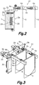
Fig. 2 is a cross-sectional view taken by the plane II-II ofFig. 1 ; -
Fig. 3 is a perspective view of a container-carrying unit belonging to the conveyor device ofFig. 1 with relatively big-sized flexible containers being carried thereon; -
Fig. 4 is a top plan view of the container-carrying unit ofFig. 3 in a straight section of the closed path and with an upper opening of the relatively big-sized flexible containers being kept closed; -
Fig. 5 is a top plan view of the container-carrying unit ofFig. 3 in a straight section of the closed path and with the upper opening of the relatively big-sized flexible containers being kept open; -
Fig. 6 is a top plan view of the container-carrying unit ofFig. 3 in a curved section of the closed path and with the upper opening of the relatively big-sized flexible containers being kept closed; -
Fig. 7 is a perspective view of a container-carrying unit belonging to the conveyor device ofFig. 1 with relatively small-sized flexible containers being carried thereon; -
Fig. 8 is a top plan view of the container-carrying unit ofFig. 7 in a straight section of the closed path and with an upper opening of the relatively small-sized flexible containers being kept open; -
Fig. 9 is a top plan view of the container-carrying unit ofFig. 7 in a curved section of the closed path and with the upper opening of the relatively small-sized flexible containers being kept closed; -
Fig. 10 is a top plan diagrammatic view of a first variant of the container-carrying unit shown inFigs. 1 to 9 ; -
Fig. 11 is a top plan diagrammatic view of a second variant of the container-carrying unit shown inFigs. 1 to 9 ; -
Fig. 12 is a top plan diagrammatic view of a container-carrying unit belonging to a conveyor device for conveying flexible containers along a packaging line according to a second embodiment of the present invention; -
Fig. 13 is a top plan diagrammatic view of a variant of the container-carrying unit shown inFig. 12 ; -
Fig. 14 is a top plan diagrammatic view of a container-carrying unit belonging to a conveyor device for conveying flexible containers along a packaging line according to a third embodiment of the present invention; -
Fig. 15 is a top plan diagrammatic view of a container-carrying unit belonging to a conveyor device for conveying flexible containers along a packaging line according to a fourth embodiment of the present invention; -
Fig. 16 is a top plan diagrammatic view of a container-carrying unit belonging to a conveyor device for conveying flexible containers along a packaging line according to a fifth embodiment of the present invention; -
Fig. 17 is a top plan diagrammatic view of a first variant of the container-carrying unit shown inFig. 16 ; -
Fig. 18 is a top plan diagrammatic view of a second variant of the container-carrying unit shown inFig. 16 ; and -
Fig. 19 is a top plan diagrammatic view of a third variant of the container-carrying unit shown inFig. 16 . - Referring first to
Figs. 1 to 9 , a conveyor device for conveying flexible containers along a packaging line according to a first embodiment of the present invention is described. - As shown in
Fig. 1 , the conveyor device comprises atrack 1 defining a closed path and a plurality of container-carryingunits 31 arranged to move along the path. The closed path defined by thetrack 1 lays in a horizontal plane and includes straight and curved sections. Each container-carryingunit 31 comprises one pair ofadjacent movers left mover 2a and aright mover 2b movably mounted on thetrack 1 for moving along the closed path. Active andreactive elements track 1 and the left andright movers Fig. 2 ) are configured according to a controlled motion system well known in the art for independently driving and controlling the left andright movers - As better shown in
Fig. 4-9 , each container-carryingunit 31 comprises one pairgripper arms left gripper arm 3a pivotally connected to theleft mover 2a by aleft articulation 6a about a vertical axis and aright gripper arm 3b pivotally connected to theright mover 2b by aright articulation 6b about a vertical axis. Each container-carryingunit 31 further comprises two pairs ofclamps left clamp 4a mounted on theleft gripper arm 3a and aright clamp 4b mounted on theright gripper arm 3b. The left andright clamps flexible container 5 at opposite side edges thereof with theflexible container 5 hanging in a vertical position. - The left and
right gripper arms unit 31 are linked together by a parallelism-keeping mechanism configured for keeping the left andright gripper arms right clamps right articulations right movers - In the first embodiment shown in
Figs. 1 to 9 , the parallelism-keeping mechanism comprises alinear guide 8 and aguide follower 9. Thelinear guide 8 is provided by a guide bar rigidly attached to theright gripper arm 3b in a position perpendicular to the left andright gripper arms guide follower 9 is provided by a linear bearing rigidly attached to theleft gripper arm 3a in a position perpendicular to the left andright gripper arms guide follower 9 being slidingly coupled to thelinear guide 8. Astop 34 at a free end of thelinear guide 8 prevents thelinear guide 8 from leaving theguide follower 9. It is to be understood that an equivalent inverse construction is possible, with thelinear guide 8 rigidly attached to theleft gripper arm 3a and theguide follower 9 rigidly attached to theright gripper arm 3b. - With this configuration, and by independently controlling the movements of each mover by means of a convenient programing of the controller of the controlled motion system, each container-carrying
unit 31 is able to grip and hold a flexible container in a vertical position regardless the format of the flexible container within a set up container size range, move the flexible container forward and backward at variable speeds along the path, keep the flexible container stationary at selected positions of the path and open and close the upper opening of each flexible container either when being stationary or in motion and either in a straight or curved section of the path. - As shown in
Fig. 2 , thetrack 1 comprises arail 32 and the aforementionedactive elements 29. Theleft mover 2a (symmetrical to theright mover 2b) haswheels 33 coupled to therail 32 and the aforementionedreactive elements 30 facing theactive elements 29 of thetrack 1. The left clamps 4a mounted on theleft gripper arm 3a (symmetrical to the right clamps 4b mounted on theright gripper arm 3b) are of a well-known type shown, for example, in the cited documentEP 3321195 A1 . - Although in the first embodiment shown in
Figs. 1 to 9 two pairs ofclamps unit 31, it is to be understood that by virtue of the parallel condition of the left andright gripper arms clamps unit 31 for gripping an equivalent number offlexible containers 5, provided that each pair of clamps comprises oneleft clamp 4a mounted on theleft gripper arm 3a and oneright clamp 4b mounted on theright gripper arm 3b. -
Fig. 4 shows the container-carryingunit 31 carrying two relatively big-sizedflexible containers 5 within the set up size range. Relatively big-sized flexible containers means, for example, flexible containers that are more than 50% of the maximum size available within the set up size range. -
Fig. 4 shows the container-carryingunit 31 in a straight section of the closed path defined by thetrack 1, with the two pairs of left andright clamps flexible containers 5 and with the left andright movers right gripper arms flexible containers 5 so as to keep their upper openings closed. -
Fig. 5 shows the container-carryingunit 31 in a straight section of the closed path defined by thetrack 1, with the two pairs of left andright clamps flexible containers 5 and with the left andright movers right gripper arms flexible containers 5 so as to keep their upper openings open. -
Fig. 6 shows the container-carryingunit 31 in a curved section of the closed path defined by thetrack 1, with the two pairs of left andright clamps flexible containers 5 and with the left andright movers right gripper arms flexible containers 5 so as to keep their upper openings closed. - It is to be understood that, although not shown, the left and
right movers right gripper arms flexible containers 5 so as to keep their upper openings open in a curved section of the closed path defined by thetrack 1. -
Fig. 7 shows the container-carryingunit 31 carrying two relatively small-sizedflexible containers 5 within the set up size range. Relatively small-sized flexible containers means, for example, flexible containers that are less than 50% of the maximum size available within the set up size range. -
Fig. 8 shows the container-carryingunit 31 in a straight section of the closed path defined by thetrack 1, with the two pairs of left andright clamps flexible containers 5 and with the left andright movers right gripper arms flexible containers 5 so as to keep their upper openings open. - It is to be understood that, although not shown, the left and
right movers right gripper arms flexible containers 5 so as to keep their upper openings closed in a straight section of the closed path defined by thetrack 1. -
Fig. 9 shows the container-carryingunit 31 in a curved section of the closed path defined by thetrack 1, with the two pairs of left andright clamps flexible containers 5 and with the left andright movers right gripper arms flexible containers 5 so as to keep their upper openings closed. - It is to be understood that, although not shown, the left and
right movers right gripper arms flexible containers 5 so as to keep their upper openings open in a curved section of the closed path defined by thetrack 1. -
Fig. 10 diagrammatically shows a container-carryingunit 31 according to a first variant of the first embodiment shown inFigs. 1 to 9 , wherein a single pair of left andright clamps right gripper arms flexible container 5. -
Fig. 11 diagrammatically shows a container-carryingunit 31 according to a second variant of the first embodiment shown inFigs. 1 to 9 , wherein four pairs of left andright clamps right gripper arms flexible containers 5. -
Fig. 12 diagrammatically shows a container-carryingunit 31 according to a second embodiment of the present invention comprising aleft arm support 7a pivotally connected to theleft mover 2a by aleft articulation 6a about a vertical axis and aright arm support 7b pivotally connected to theright mover 2b by aright articulation 6b about a vertical axis. A firstleft gripper arm 3a and a parallel secondleft gripper arm 3c are rigidly fixed to theleft arm support 7a. A firstright gripper arm 3b and a parallel secondright gripper arm 3d are rigidly fixed to theright arm support 7b. The firstleft gripper arm 3a, the secondleft gripper arm 3c, the firstright gripper arm 3b and the secondright gripper arm 3d are mutually parallel. - In this second embodiment, a first
left clamp 4a is mounted on the firstleft gripper arm 3a, a secondleft clamp 4c is mounted on the secondleft gripper arm 3c, a firstright clamp 4b is mounted on the firstright gripper arm 3b, and a secondright clamp 4d is mounted on the secondright gripper arm 3d. The left and right arm supports 7a, 7b are arranged such that the firstleft gripper arm 3a is paired with the secondright gripper arm 3d and the secondleft gripper arm 3c is paired with the firstright gripper arm 3b, and such that the firstleft clamp 4a is paired with the secondright clamp 4d constituting a left pair ofclamps left clamp 4c is paired with the firstright clamp 4b constituting a right pair ofclamps flexible containers 5 at opposite side edges thereof with theflexible containers 5 in a vertical position. - The parallelism-keeping mechanism of the second embodiment comprises a
linear guide 8 perpendicular to the first and second left andright gripper arms guide follower 9 attached to the other of the left and right arm supports 7a, 7b and slidingly coupled to thelinear guide 8 although alternative parallelism-keeping mechanism will easily occur to one skilled person. -
Fig. 13 diagrammatically shows a variant of the container-carryingunit 31 according to the second embodiment, wherein two left pairs ofclamps clamps flexible containers 5, although it will be understood that any plural number of left and right pairs ofclamps left clamp 4a mounted on the firstleft gripper arm 3a and one secondright clamp 4d mounted on the secondright gripper arm 3d. Each right pair of clamps comprises one secondleft clamp 4c mounted on the secondleft gripper arm 3c and one firstright clamp 4b mounted on the firstright gripper arm 3b. -
Fig. 14 diagrammatically shows a container-carryingunit 31 according to a third embodiment of the present invention comprising aleft gripper arm 3a pivotally connected to aleft mover 2a by aleft articulation 6a about a vertical axis and aright gripper arm 3b pivotally connected to aright mover 2b by aright articulation 6b about a vertical axis. The container-carryingunit 31 further comprises two pairs ofclamps left clamp 4a mounted on theleft gripper arm 3a and aright clamp 4b mounted on theright gripper arm 3b. A parallelism-keeping mechanism is provided comprising alinear guide bar 10, aleft guide follower 11a attached to theleft gripper arm 3a in a position perpendicular thereto and aright guide follower 11b attached to theright gripper arm 3b in a position perpendicular thereto. Both theleft guide follower 11a and theright guide follower 11b are slidingly coupled to thelinear guide bar 10. Preferably, stops (not shown) are provided at both free ends of thelinear guide bar 10 to prevent thelinear guide bar 10 from leaving the left and right guidefollowers -
Fig. 15 diagrammatically shows a container-carryingunit 31 according to a fourth embodiment of the present invention comprising aleft gripper arm 3a pivotally connected to aleft mover 2a by aleft articulation 6a about a vertical axis and aright gripper arm 3b pivotally connected to aright mover 2b by aright articulation 6b about a vertical axis. The container-carryingunit 31 further comprises two pairs ofclamps left clamp 4a mounted on theleft gripper arm 3a and aright clamp 4b mounted on theright gripper arm 3b, although it is to be understood that any number of pairs ofclamps - In this fourth embodiment, a parallelism-keeping mechanism is provided comprising a left
linear guide 12a attached to theleft gripper arm 3a in a position parallel thereto and a rightlinear guide 12b attached to theright gripper arm 3b in a position parallel thereto, afirst rocker bar 13a and asecond rocker bar 13b. Thefirst rocker bar 13a has a first end pivotally connected to theleft gripper arm 3a by aleft articulation 14a about a vertical axis and a second end pivotally connected to aright guide follower 15b slidingly coupled to the rightlinear guide 12b. Thesecond rocker bar 13b has a first end pivotally connected to theright gripper arm 3b by aright articulation 14b about a vertical axis and a second end pivotally connected to aleft guide follower 15a slidingly coupled to the leftlinear guide 12a. The first andsecond rocker bars intermediate articulation 16 about a vertical axis. -
Fig. 16 diagrammatically shows a container-carryingunit 31 according to a fifth embodiment of the present invention comprising aleft gripper arm 3a pivotally connected to aleft mover 2a by aleft articulation 6a about a vertical axis and aright gripper arm 3b pivotally connected to aright mover 2b by aright articulation 6b about a vertical axis. The container-carryingunit 31 further comprises two pairs ofclamps left clamp 4a mounted on theleft gripper arm 3a and aright clamp 4b mounted on theright gripper arm 3b, although it is to be understood that any number of pairs ofclamps - In this fifth embodiment, a parallelism-keeping mechanism is provided comprising an
intermediate body 21, first and secondleft rocker bars left rocker bars left gripper arm 3a by respective first and secondleft articulations intermediate body 21 by respective first and second leftintermediate articulations right gripper arm 3b by respective first and secondright articulations intermediate body 21 by respective first and second rightintermediate articulations 22b, 23b about vertical axes. - The distances between the first and second
left articulations intermediate articulations left rocker bars left gripper arm 3a and theintermediate body 21 form together a left articulated parallelogram. The distances between the first and secondright articulations intermediate articulations 22b, 23b are configured such that the first and second right rocker bars 17b, 18b, theright gripper arm 3b and theintermediate body 21 form together a right articulated parallelogram symmetric of the left articulated parallelogram. - In the fifth embodiment shown in
Fig. 16 , the parallelism-keeping mechanism further comprises left and right toothed wheels 24a, 24b coaxial to the second left and rightintermediate articulations left rocker bars right gripper arms right clamps -
Fig. 17 diagrammatically shows a first variant of the container-carryingunit 31 of the fifth embodiment which only differs from the fifth embodiment shown inFig. 16 in that the second ends of the first left and right rocker bars 17a, 17b are pivotally connected to theintermediate body 21 by a centralcoaxial articulation 35 about a common vertical axis. -
Fig. 18 diagrammatically shows a second variant of the container-carryingunit 31 of the fifth embodiment shown inFig. 16 , wherein the parallelism-keeping mechanism comprises, instead of the left and right toothed wheels 24a, 24b, an intermediatelinear guide 25 rigidly attached to theintermediate body 21 in a position parallel to the left andright gripper arms left rocker bar 26a and a thirdright rocker bar 26b. The thirdleft rocker bar 26a has a first end pivotally connected to theleft gripper arm 3a by a thirdleft articulation 27a about a vertical axis and a second end pivotally connected to aguide follower 28 slidingly coupled to the intermediatelinear guide 25. The thirdright rocker bar 26b has a first end pivotally connected to theright gripper arm 3b by a thirdright articulation 27b about a vertical axis and a second end pivotally connected to theguide follower 28. The intermediatelinear guide 25 protrudes outwardly from theintermediate body 21 and the connections of the second ends of the third left and right rocker bars 26a, 26b to theguide follower 28 are coaxial. -
Fig. 19 diagrammatically shows a third variant of the container-carryingunit 31 of the fifth embodiment which only differs from the second variant shown inFig. 18 in that the intermediatelinear guide 25 protrudes inwardly from theintermediate body 21. - The scope of the invention is defined in the attached claims.
Claims (11)
- A conveyor device for conveying flexible containers along a packaging line, comprising:a track (1) defining a closed path;at least one pair of movers (2a, 2b) including a left mover (2a) and a right mover (2b) movably mounted on the track (1) for moving along the path;active and reactive (29, 30) elements associated with the track (1) and the left and right movers (2a, 2b) and configured for independently driving and controlling the left and right movers (2a, 2b) along the path;at least one pair of gripper arms (3a, 3b) including a left gripper arm (3a) connected to the left mover (2a) and a right gripper arm (3b) connected to the right mover (2b);at least one pair of clamps (4a, 4b) including a left clamp (4a) mounted on the left gripper arm (3a) and a right clamp (4b) mounted on the right gripper arm (3b), the left and right clamps (4a, 4b) being configured for gripping a flexible container (5) at opposite side edges thereof with the flexible container (5) in a vertical position;wherein the closed path defined by the track (1) lays in a horizontal plane and includes straight and curved sections; andthe left gripper arm (3a) is pivotally connected to the left mover (2a) by a left articulation (6a) about a vertical axis and the right gripper arm (3b) is pivotally connected to the right mover (2b) by a right articulation (6b) about a vertical axis;the conveyor device being characterized in that:
the left and right gripper arms (3a, 3b) are linked together by a parallelism-keeping mechanism configured for keeping the left and right gripper arms (3a, 3b) mutually parallel and with the left and right clamps (4a, 4b) facing each other in both the straight and curved sections of the path even when a distance between the left and right articulations (6a, 6b) is varied due to the relative movements of the left and right movers (2a, 2b). - The conveyor device of claim 1, wherein:the left gripper arm (3a) is a first left gripper arm (3a) fixed to a left arm support (7a) and the right gripper arm (3b) is a first right gripper arm (3b) fixed to a right arm support (7b);a second left gripper arm (3c) parallel to the first left gripper arm (3a) is fixed to the left arm support (7a) and a second right gripper arm (3d) parallel to the first right gripper arm (3b) is fixed to the right arm support (7b);the left arm support (7a) is pivotally connected to the left mover (2a) by the left articulation (6a) and the right arm support (7b) is pivotally connected to the right mover (2b) by the right articulation (6b);the left clamp (4a) is a first left clamp (4a) mounted on the first left gripper arm (3a) and the right clamp (4b) is a first right clamp (4b) mounted on the first right gripper arm (3b);a second left clamp (4c) is mounted on the second left gripper arm (3c) and a second right clamp (4d) is mounted on the second right gripper arm (3d);the second left clamp (4c) is paired with the first right clamp (4b) and the second right clamp (4d) is paired with the first left clamp (4a) for gripping a pair of flexible containers (5) at opposite side edges thereof with the flexible containers (5) in a vertical position.
- The conveyor device of claim 1, wherein a plurality of pairs of clamps (4a, 4b) are provided for gripping a plurality of flexible containers (5), each pair of clamps comprising one left clamp (4a) mounted on the left gripper arm (3a) and one right clamp (4b) mounted on the right gripper arm (3b).
- The conveyor device of claim 2, wherein a plurality of left pairs of clamps (4a, 4d) and a plurality of right pairs of clamps (4b, 4c) are provided for gripping a plurality of flexible containers (5), each left pair of clamps comprising one first left clamp (4a) mounted on the first left gripper arm (3a) and one second right clamp (4d) mounted on the second right gripper arm (3d), and each right pair of clamps comprising one second left clamp (4c) mounted on the second left gripper arm (3c) and one first right clamp (4b) mounted on the first right gripper arm (3b).
- The conveyor device of claim 1 or 3, wherein the parallelism-keeping mechanism comprises a linear guide (8) perpendicular to the left and right gripper arms (3a, 3b) attached to one of the left and right gripper arms (3a, 3b) and a guide follower (9) attached to the other of the left and right gripper arms (3a, 3b) and slidingly coupled to the linear guide (8).
- The conveyor device of claim 2 or 4, wherein the parallelism-keeping mechanism comprises a linear guide (8) perpendicular to the first and second left and right gripper arms (3a-3d) attached to one of the left and right arm supports (7a, 7b) and a guide follower (9) attached to the other of the left and right arm supports (7a, 7b) and slidingly coupled to the linear guide (8).
- The conveyor device of claim 1 or 3, wherein the parallelism-keeping mechanism comprises a linear guide bar (10), a left guide follower (11a) perpendicular to the left gripper arm (3a) attached to the left gripper arm (3a) and slidingly coupled to the linear guide bar (10) and a right guide follower (11b) perpendicular to the right gripper arm (3b) attached to the right gripper arm (3b) and slidingly coupled to the linear guide bar (10).
- The conveyor device of claim 1 or 3, wherein the parallelism-keeping mechanism comprises a left linear guide (12a) parallel and attached to the left gripper arm (3a), a right linear guide (12b) parallel and attached to the right gripper arm (3b), a first rocker bar (13a) having a first end pivotally connected to the left gripper arm (3a) by a left articulation (14a) about a vertical axis and a second end pivotally connected to a right guide follower (15b) slidingly coupled to the right linear guide (12b), and a second rocker bar (13b) having a first end pivotally connected to the right gripper arm (3b) by a right articulation (14b) about a vertical axis and a second end pivotally connected to a left guide follower (15a) slidingly coupled to the left linear guide (12a), wherein the first and second rocker bars (13a, 13b) are pivotally connected to one another at an intermediate crossing point thereof by an intermediate articulation (16) about a vertical axis.
- The conveyor device of claim 1 or 3, wherein the parallelism-keeping mechanism comprises:first and second left rocker bars (17a, 18a) having respective first ends pivotally connected to the left gripper arm (3a) by respective first and second left articulations (19a, 20a) about vertical axes and respective second ends pivotally connected to an intermediate body (21) by respective first and second left intermediate articulations (22a, 23a) about vertical axes;first and second right rocker bars (17b, 18b) having respective first ends pivotally connected to the right gripper arm (3b) by respective first and second right articulations (19b, 20b) about vertical axes and respective second ends connected to the intermediate body (21) by respective first and second right intermediate articulations (22b, 23b) about vertical axes;wherein the first and second left rocker bars (17a, 18a), the left gripper arm (3a) and the intermediate body (21) form together a left articulated parallelogram and the first and second right rocker bars (17b, 18b), the right gripper arm (3b) and the intermediate body (21) form together a right articulated parallelogram.
- The conveyor device of claim 9, wherein the parallelism-keeping mechanism further comprises mutually meshed left and right toothed wheels (24a, 24b) coaxial to the second left and right intermediate articulations (23a, 23b) and fixed to the second left and right rocker bars (18a, 18b), respectively, wherein the left and right toothed wheels (24a, 24b) have a same diameter.
- The conveyor device of claim 9, wherein the parallelism-keeping mechanism further comprises an intermediate linear guide (25) parallel to the left and right gripper arms (3a, 3b) attached to the intermediate body (21), a third left rocker bar (26a) having a first end pivotally connected to the left gripper arm (3a) by a third left articulation (27a) about a vertical axis and a second end pivotally connected to a guide follower (28) slidingly coupled to the intermediate linear guide (25), and a third right rocker bar (26b) having a first end pivotally connected to the right gripper arm (3b) by a third right articulation (27b) about a vertical axis and a second end pivotally connected to the guide follower (28).
Priority Applications (4)
| Application Number | Priority Date | Filing Date | Title |
|---|---|---|---|
| EP19382421.6A EP3744649B1 (en) | 2019-05-27 | 2019-05-27 | Conveyor device for conveying flexible containers along a packaging line |
| ES19382421T ES2894297T3 (en) | 2019-05-27 | 2019-05-27 | Conveyor device for transporting flexible containers along a packaging line |
| PCT/EP2020/052044 WO2020239272A1 (en) | 2019-05-27 | 2020-01-28 | Conveyor device for conveying flexible containers along a packaging line |
| US17/613,017 US11787645B2 (en) | 2019-05-27 | 2020-01-28 | Conveyor device for conveying flexible containers along a packaging line |
Applications Claiming Priority (1)
| Application Number | Priority Date | Filing Date | Title |
|---|---|---|---|
| EP19382421.6A EP3744649B1 (en) | 2019-05-27 | 2019-05-27 | Conveyor device for conveying flexible containers along a packaging line |
Publications (2)
| Publication Number | Publication Date |
|---|---|
| EP3744649A1 EP3744649A1 (en) | 2020-12-02 |
| EP3744649B1 true EP3744649B1 (en) | 2021-07-07 |
Family
ID=66685544
Family Applications (1)
| Application Number | Title | Priority Date | Filing Date |
|---|---|---|---|
| EP19382421.6A Active EP3744649B1 (en) | 2019-05-27 | 2019-05-27 | Conveyor device for conveying flexible containers along a packaging line |
Country Status (4)
| Country | Link |
|---|---|
| US (1) | US11787645B2 (en) |
| EP (1) | EP3744649B1 (en) |
| ES (1) | ES2894297T3 (en) |
| WO (1) | WO2020239272A1 (en) |
Families Citing this family (4)
| Publication number | Priority date | Publication date | Assignee | Title |
|---|---|---|---|---|
| IT201800009193A1 (en) * | 2018-10-05 | 2020-04-05 | Gd Spa | Apparatus and method for performing operations on semi-finished devices, in particular for producing disposable cartridges for electronic cigarettes |
| EP4089040A1 (en) * | 2021-05-11 | 2022-11-16 | Fameccanica.Data S.p.A. | Adaptive carrier unit and transfer system |
| DE102021129702A1 (en) * | 2021-11-15 | 2023-05-17 | Krones Aktiengesellschaft | Transport of objects with different formats |
| WO2023189985A1 (en) * | 2022-03-31 | 2023-10-05 | 株式会社フジシール | Conveyance system and program |
Citations (6)
| Publication number | Priority date | Publication date | Assignee | Title |
|---|---|---|---|---|
| WO2005051812A1 (en) | 2003-10-28 | 2005-06-09 | Aew Delford Systems | Improved pick and place gripper |
| US20160176659A1 (en) | 2014-12-17 | 2016-06-23 | Uhlmann Pac-Systeme Gmbh & Co. Kg | Transport device for conveying products |
| EP2818437B1 (en) | 2013-06-26 | 2016-11-16 | Bossar Packaging, S.A. | Flexible package transport device for packaging machines |
| US20170247201A1 (en) | 2014-11-24 | 2017-08-31 | Beckhoff Automation Gmbh | Xy table for a linear transport system |
| EP3321195A1 (en) | 2016-11-10 | 2018-05-16 | Mespack, S.L. | Horizontal-type automatic packaging machine |
| JP2018172140A (en) | 2017-03-31 | 2018-11-08 | 三菱重工機械システム株式会社 | Article conveyance device |
Family Cites Families (15)
| Publication number | Priority date | Publication date | Assignee | Title |
|---|---|---|---|---|
| US4453882A (en) * | 1982-04-27 | 1984-06-12 | Emerson Electric Co. | Longreach linear pick-and-place assembly apparatus |
| DE3637638A1 (en) * | 1986-11-05 | 1988-05-11 | Kammann Maschf Werner | DEVICE FOR DECORATING OBJECTS |
| DE19919434A1 (en) * | 1999-04-29 | 2000-11-02 | Schuler Pressen Gmbh & Co | Part transfer facility |
| US6530735B1 (en) * | 2000-06-22 | 2003-03-11 | Amkor Technology, Inc. | Gripper assembly |
| US6876107B2 (en) | 2002-06-05 | 2005-04-05 | Jacobs Automation | Controlled motion system |
| US7748517B2 (en) * | 2004-02-04 | 2010-07-06 | Goss International Americas, Inc. | Signature transport device |
| DE102006028796A1 (en) * | 2006-06-23 | 2007-12-27 | Khs Ag | Apparatus for treating flexible hose-like structures with at least one opening |
| ES2522793B1 (en) | 2013-05-15 | 2015-08-10 | Pfm Ibérica Packaging Machinery, S.A. | Device for transport in a packaging line of suspended flexible held containers |
| KR101487283B1 (en) * | 2013-08-13 | 2015-01-29 | 주식회사 한독자동기 | Grip apparatus for rotary packaging machine |
| JP6140086B2 (en) * | 2014-02-06 | 2017-05-31 | 東洋自動機株式会社 | Bag transfer device |
| JP6746467B2 (en) * | 2016-10-27 | 2020-08-26 | 東洋自動機株式会社 | Gripper device of bag packing machine |
| EP3336020A1 (en) * | 2016-12-14 | 2018-06-20 | Toyo Jidoki Co., Ltd. | Container conveying apparatus |
| EP3409447B1 (en) * | 2017-05-30 | 2021-04-21 | Tetra Laval Holdings & Finance S.A. | Apparatus for sealing the top of a package for a food product and system for forming and filling a food package |
| US10600441B1 (en) * | 2018-12-07 | 2020-03-24 | International Business Machines Corporation | Disc gripper for storage discs |
| WO2021019053A1 (en) * | 2019-07-30 | 2021-02-04 | Anheuser-Busch Inbev S.A. | An article picking and treating apparatus |
-
2019
- 2019-05-27 ES ES19382421T patent/ES2894297T3/en active Active
- 2019-05-27 EP EP19382421.6A patent/EP3744649B1/en active Active
-
2020
- 2020-01-28 US US17/613,017 patent/US11787645B2/en active Active
- 2020-01-28 WO PCT/EP2020/052044 patent/WO2020239272A1/en active Application Filing
Patent Citations (6)
| Publication number | Priority date | Publication date | Assignee | Title |
|---|---|---|---|---|
| WO2005051812A1 (en) | 2003-10-28 | 2005-06-09 | Aew Delford Systems | Improved pick and place gripper |
| EP2818437B1 (en) | 2013-06-26 | 2016-11-16 | Bossar Packaging, S.A. | Flexible package transport device for packaging machines |
| US20170247201A1 (en) | 2014-11-24 | 2017-08-31 | Beckhoff Automation Gmbh | Xy table for a linear transport system |
| US20160176659A1 (en) | 2014-12-17 | 2016-06-23 | Uhlmann Pac-Systeme Gmbh & Co. Kg | Transport device for conveying products |
| EP3321195A1 (en) | 2016-11-10 | 2018-05-16 | Mespack, S.L. | Horizontal-type automatic packaging machine |
| JP2018172140A (en) | 2017-03-31 | 2018-11-08 | 三菱重工機械システム株式会社 | Article conveyance device |
Also Published As
| Publication number | Publication date |
|---|---|
| EP3744649A1 (en) | 2020-12-02 |
| US20220315356A1 (en) | 2022-10-06 |
| US11787645B2 (en) | 2023-10-17 |
| WO2020239272A1 (en) | 2020-12-03 |
| ES2894297T3 (en) | 2022-02-14 |
Similar Documents
| Publication | Publication Date | Title |
|---|---|---|
| EP3744649B1 (en) | Conveyor device for conveying flexible containers along a packaging line | |
| CN102020111B (en) | Gripper unit for supporting and transporting articles | |
| US8162127B2 (en) | Dynamic storage for objects | |
| US8448579B2 (en) | Article transport facility | |
| EP2522583B1 (en) | Transfer device for transferring empty flexible packages from a package row to two or more package rows applicable to an automatic packaging machine | |
| US9650165B2 (en) | Tray sealer | |
| EP2818437B1 (en) | Flexible package transport device for packaging machines | |
| RU2008127256A (en) | DEVICE AND METHOD FOR LAYING FIBER HARNESS | |
| EP2942298B1 (en) | Line-changing device for an automatic horizontal flexible container forming and filling machine | |
| JP2018172140A (en) | Article conveyance device | |
| IT201800020914A1 (en) | GROUP AND METHOD FOR THE TRANSFER AND ORIENTATION OF CONTAINERS | |
| US5884750A (en) | Apparatus for transferring substantially round, fragile articles, such as for instance eggs | |
| US5343999A (en) | Feeding apparatus | |
| JPH08226030A (en) | Pipe exchanging mechanism for pipe exchanging of full bobbinor empty tube or both of them | |
| US4690050A (en) | Transfer system for article printing machine | |
| US6543766B2 (en) | Device for forming and transferring ordered stacks of bank notes | |
| EP2108623A2 (en) | Transfer assembly for transferring glass articles | |
| KR20130121882A (en) | Apparatus, method of operation of same and tools for use with apparatus | |
| CN104280563A (en) | Device for transport | |
| JP4524828B2 (en) | Article transfer device | |
| US4955464A (en) | Conveyor device for transporting workpieces | |
| JP4307978B2 (en) | Container transfer device | |
| CN207328964U (en) | A kind of bottle automatic bag sheathing device | |
| US6374992B1 (en) | Unstable article conveying device with diverter | |
| EP1627698B1 (en) | Panel transportation device |
Legal Events
| Date | Code | Title | Description |
|---|---|---|---|
| PUAI | Public reference made under article 153(3) epc to a published international application that has entered the european phase |
Free format text: ORIGINAL CODE: 0009012 |
|
| STAA | Information on the status of an ep patent application or granted ep patent |
Free format text: STATUS: THE APPLICATION HAS BEEN PUBLISHED |
|
| AK | Designated contracting states |
Kind code of ref document: A1 Designated state(s): AL AT BE BG CH CY CZ DE DK EE ES FI FR GB GR HR HU IE IS IT LI LT LU LV MC MK MT NL NO PL PT RO RS SE SI SK SM TR |
|
| AX | Request for extension of the european patent |
Extension state: BA ME |
|
| STAA | Information on the status of an ep patent application or granted ep patent |
Free format text: STATUS: REQUEST FOR EXAMINATION WAS MADE |
|
| 17P | Request for examination filed |
Effective date: 20210203 |
|
| RBV | Designated contracting states (corrected) |
Designated state(s): AL AT BE BG CH CY CZ DE DK EE ES FI FR GB GR HR HU IE IS IT LI LT LU LV MC MK MT NL NO PL PT RO RS SE SI SK SM TR |
|
| GRAP | Despatch of communication of intention to grant a patent |
Free format text: ORIGINAL CODE: EPIDOSNIGR1 |
|
| STAA | Information on the status of an ep patent application or granted ep patent |
Free format text: STATUS: GRANT OF PATENT IS INTENDED |
|
| INTG | Intention to grant announced |
Effective date: 20210326 |
|
| GRAS | Grant fee paid |
Free format text: ORIGINAL CODE: EPIDOSNIGR3 |
|
| GRAA | (expected) grant |
Free format text: ORIGINAL CODE: 0009210 |
|
| STAA | Information on the status of an ep patent application or granted ep patent |
Free format text: STATUS: THE PATENT HAS BEEN GRANTED |
|
| AK | Designated contracting states |
Kind code of ref document: B1 Designated state(s): AL AT BE BG CH CY CZ DE DK EE ES FI FR GB GR HR HU IE IS IT LI LT LU LV MC MK MT NL NO PL PT RO RS SE SI SK SM TR |
|
| REG | Reference to a national code |
Ref country code: GB Ref legal event code: FG4D |
|
| REG | Reference to a national code |
Ref country code: AT Ref legal event code: REF Ref document number: 1408384 Country of ref document: AT Kind code of ref document: T Effective date: 20210715 |
|
| REG | Reference to a national code |
Ref country code: DE Ref legal event code: R096 Ref document number: 602019005951 Country of ref document: DE |
|
| REG | Reference to a national code |
Ref country code: IE Ref legal event code: FG4D |
|
| REG | Reference to a national code |
Ref country code: LT Ref legal event code: MG9D |
|
| REG | Reference to a national code |
Ref country code: NL Ref legal event code: MP Effective date: 20210707 |
|
| REG | Reference to a national code |
Ref country code: AT Ref legal event code: MK05 Ref document number: 1408384 Country of ref document: AT Kind code of ref document: T Effective date: 20210707 |
|
| PG25 | Lapsed in a contracting state [announced via postgrant information from national office to epo] |
Ref country code: SE Free format text: LAPSE BECAUSE OF FAILURE TO SUBMIT A TRANSLATION OF THE DESCRIPTION OR TO PAY THE FEE WITHIN THE PRESCRIBED TIME-LIMIT Effective date: 20210707 Ref country code: RS Free format text: LAPSE BECAUSE OF FAILURE TO SUBMIT A TRANSLATION OF THE DESCRIPTION OR TO PAY THE FEE WITHIN THE PRESCRIBED TIME-LIMIT Effective date: 20210707 Ref country code: NO Free format text: LAPSE BECAUSE OF FAILURE TO SUBMIT A TRANSLATION OF THE DESCRIPTION OR TO PAY THE FEE WITHIN THE PRESCRIBED TIME-LIMIT Effective date: 20211007 Ref country code: NL Free format text: LAPSE BECAUSE OF FAILURE TO SUBMIT A TRANSLATION OF THE DESCRIPTION OR TO PAY THE FEE WITHIN THE PRESCRIBED TIME-LIMIT Effective date: 20210707 Ref country code: PT Free format text: LAPSE BECAUSE OF FAILURE TO SUBMIT A TRANSLATION OF THE DESCRIPTION OR TO PAY THE FEE WITHIN THE PRESCRIBED TIME-LIMIT Effective date: 20211108 Ref country code: HR Free format text: LAPSE BECAUSE OF FAILURE TO SUBMIT A TRANSLATION OF THE DESCRIPTION OR TO PAY THE FEE WITHIN THE PRESCRIBED TIME-LIMIT Effective date: 20210707 Ref country code: FI Free format text: LAPSE BECAUSE OF FAILURE TO SUBMIT A TRANSLATION OF THE DESCRIPTION OR TO PAY THE FEE WITHIN THE PRESCRIBED TIME-LIMIT Effective date: 20210707 Ref country code: AT Free format text: LAPSE BECAUSE OF FAILURE TO SUBMIT A TRANSLATION OF THE DESCRIPTION OR TO PAY THE FEE WITHIN THE PRESCRIBED TIME-LIMIT Effective date: 20210707 Ref country code: BG Free format text: LAPSE BECAUSE OF FAILURE TO SUBMIT A TRANSLATION OF THE DESCRIPTION OR TO PAY THE FEE WITHIN THE PRESCRIBED TIME-LIMIT Effective date: 20211007 Ref country code: LT Free format text: LAPSE BECAUSE OF FAILURE TO SUBMIT A TRANSLATION OF THE DESCRIPTION OR TO PAY THE FEE WITHIN THE PRESCRIBED TIME-LIMIT Effective date: 20210707 |
|
| REG | Reference to a national code |
Ref country code: ES Ref legal event code: FG2A Ref document number: 2894297 Country of ref document: ES Kind code of ref document: T3 Effective date: 20220214 |
|
| PG25 | Lapsed in a contracting state [announced via postgrant information from national office to epo] |
Ref country code: PL Free format text: LAPSE BECAUSE OF FAILURE TO SUBMIT A TRANSLATION OF THE DESCRIPTION OR TO PAY THE FEE WITHIN THE PRESCRIBED TIME-LIMIT Effective date: 20210707 Ref country code: LV Free format text: LAPSE BECAUSE OF FAILURE TO SUBMIT A TRANSLATION OF THE DESCRIPTION OR TO PAY THE FEE WITHIN THE PRESCRIBED TIME-LIMIT Effective date: 20210707 Ref country code: GR Free format text: LAPSE BECAUSE OF FAILURE TO SUBMIT A TRANSLATION OF THE DESCRIPTION OR TO PAY THE FEE WITHIN THE PRESCRIBED TIME-LIMIT Effective date: 20211008 |
|
| REG | Reference to a national code |
Ref country code: DE Ref legal event code: R026 Ref document number: 602019005951 Country of ref document: DE |
|
| PLBI | Opposition filed |
Free format text: ORIGINAL CODE: 0009260 |
|
| PLAX | Notice of opposition and request to file observation + time limit sent |
Free format text: ORIGINAL CODE: EPIDOSNOBS2 |
|
| PG25 | Lapsed in a contracting state [announced via postgrant information from national office to epo] |
Ref country code: DK Free format text: LAPSE BECAUSE OF FAILURE TO SUBMIT A TRANSLATION OF THE DESCRIPTION OR TO PAY THE FEE WITHIN THE PRESCRIBED TIME-LIMIT Effective date: 20210707 |
|
| 26 | Opposition filed |
Opponent name: PI, RAFAEL Effective date: 20220406 |
|
| PG25 | Lapsed in a contracting state [announced via postgrant information from national office to epo] |
Ref country code: SM Free format text: LAPSE BECAUSE OF FAILURE TO SUBMIT A TRANSLATION OF THE DESCRIPTION OR TO PAY THE FEE WITHIN THE PRESCRIBED TIME-LIMIT Effective date: 20210707 Ref country code: SK Free format text: LAPSE BECAUSE OF FAILURE TO SUBMIT A TRANSLATION OF THE DESCRIPTION OR TO PAY THE FEE WITHIN THE PRESCRIBED TIME-LIMIT Effective date: 20210707 Ref country code: RO Free format text: LAPSE BECAUSE OF FAILURE TO SUBMIT A TRANSLATION OF THE DESCRIPTION OR TO PAY THE FEE WITHIN THE PRESCRIBED TIME-LIMIT Effective date: 20210707 Ref country code: EE Free format text: LAPSE BECAUSE OF FAILURE TO SUBMIT A TRANSLATION OF THE DESCRIPTION OR TO PAY THE FEE WITHIN THE PRESCRIBED TIME-LIMIT Effective date: 20210707 Ref country code: CZ Free format text: LAPSE BECAUSE OF FAILURE TO SUBMIT A TRANSLATION OF THE DESCRIPTION OR TO PAY THE FEE WITHIN THE PRESCRIBED TIME-LIMIT Effective date: 20210707 Ref country code: AL Free format text: LAPSE BECAUSE OF FAILURE TO SUBMIT A TRANSLATION OF THE DESCRIPTION OR TO PAY THE FEE WITHIN THE PRESCRIBED TIME-LIMIT Effective date: 20210707 |
|
| PLBB | Reply of patent proprietor to notice(s) of opposition received |
Free format text: ORIGINAL CODE: EPIDOSNOBS3 |
|
| REG | Reference to a national code |
Ref country code: CH Ref legal event code: PL |
|
| REG | Reference to a national code |
Ref country code: BE Ref legal event code: MM Effective date: 20220531 |
|
| PG25 | Lapsed in a contracting state [announced via postgrant information from national office to epo] |
Ref country code: MC Free format text: LAPSE BECAUSE OF FAILURE TO SUBMIT A TRANSLATION OF THE DESCRIPTION OR TO PAY THE FEE WITHIN THE PRESCRIBED TIME-LIMIT Effective date: 20210707 Ref country code: LU Free format text: LAPSE BECAUSE OF NON-PAYMENT OF DUE FEES Effective date: 20220527 Ref country code: LI Free format text: LAPSE BECAUSE OF NON-PAYMENT OF DUE FEES Effective date: 20220531 Ref country code: CH Free format text: LAPSE BECAUSE OF NON-PAYMENT OF DUE FEES Effective date: 20220531 |
|
| PG25 | Lapsed in a contracting state [announced via postgrant information from national office to epo] |
Ref country code: IE Free format text: LAPSE BECAUSE OF NON-PAYMENT OF DUE FEES Effective date: 20220527 |
|
| PG25 | Lapsed in a contracting state [announced via postgrant information from national office to epo] |
Ref country code: BE Free format text: LAPSE BECAUSE OF NON-PAYMENT OF DUE FEES Effective date: 20220531 |
|
| P01 | Opt-out of the competence of the unified patent court (upc) registered |
Effective date: 20230330 |
|
| PGFP | Annual fee paid to national office [announced via postgrant information from national office to epo] |
Ref country code: IT Payment date: 20230518 Year of fee payment: 5 Ref country code: FR Payment date: 20230525 Year of fee payment: 5 Ref country code: ES Payment date: 20230615 Year of fee payment: 5 Ref country code: DE Payment date: 20230530 Year of fee payment: 5 |
|
| PGFP | Annual fee paid to national office [announced via postgrant information from national office to epo] |
Ref country code: GB Payment date: 20230529 Year of fee payment: 5 |
|
| APBM | Appeal reference recorded |
Free format text: ORIGINAL CODE: EPIDOSNREFNO |
|
| APBP | Date of receipt of notice of appeal recorded |
Free format text: ORIGINAL CODE: EPIDOSNNOA2O |
|
| APAH | Appeal reference modified |
Free format text: ORIGINAL CODE: EPIDOSCREFNO |
|
| APBM | Appeal reference recorded |
Free format text: ORIGINAL CODE: EPIDOSNREFNO |
|
| APBP | Date of receipt of notice of appeal recorded |
Free format text: ORIGINAL CODE: EPIDOSNNOA2O |
|
| PLAB | Opposition data, opponent's data or that of the opponent's representative modified |
Free format text: ORIGINAL CODE: 0009299OPPO |
|
| R26 | Opposition filed (corrected) |
Opponent name: PI, RAFAEL Effective date: 20220406 |
|
| APBQ | Date of receipt of statement of grounds of appeal recorded |
Free format text: ORIGINAL CODE: EPIDOSNNOA3O |
|
| APBQ | Date of receipt of statement of grounds of appeal recorded |
Free format text: ORIGINAL CODE: EPIDOSNNOA3O |
|
| PG25 | Lapsed in a contracting state [announced via postgrant information from national office to epo] |
Ref country code: MK Free format text: LAPSE BECAUSE OF FAILURE TO SUBMIT A TRANSLATION OF THE DESCRIPTION OR TO PAY THE FEE WITHIN THE PRESCRIBED TIME-LIMIT Effective date: 20210707 Ref country code: CY Free format text: LAPSE BECAUSE OF FAILURE TO SUBMIT A TRANSLATION OF THE DESCRIPTION OR TO PAY THE FEE WITHIN THE PRESCRIBED TIME-LIMIT Effective date: 20210707 |