EP3744129B1 - Configuration de signal de réveil multi-cellule - Google Patents
Configuration de signal de réveil multi-cellule Download PDFInfo
- Publication number
- EP3744129B1 EP3744129B1 EP19702056.3A EP19702056A EP3744129B1 EP 3744129 B1 EP3744129 B1 EP 3744129B1 EP 19702056 A EP19702056 A EP 19702056A EP 3744129 B1 EP3744129 B1 EP 3744129B1
- Authority
- EP
- European Patent Office
- Prior art keywords
- area
- wus
- sub
- cell
- configuration data
- Prior art date
- Legal status (The legal status is an assumption and is not a legal conclusion. Google has not performed a legal analysis and makes no representation as to the accuracy of the status listed.)
- Active
Links
- 238000000034 method Methods 0.000 claims description 59
- 238000004891 communication Methods 0.000 claims description 38
- 238000012772 sequence design Methods 0.000 claims description 22
- 230000008054 signal transmission Effects 0.000 claims description 21
- 230000005540 biological transmission Effects 0.000 description 73
- 238000005259 measurement Methods 0.000 description 27
- 230000001413 cellular effect Effects 0.000 description 19
- 238000012545 processing Methods 0.000 description 17
- 230000011664 signaling Effects 0.000 description 16
- 230000007480 spreading Effects 0.000 description 12
- 230000006870 function Effects 0.000 description 8
- 238000007726 management method Methods 0.000 description 8
- 230000007704 transition Effects 0.000 description 7
- 238000005265 energy consumption Methods 0.000 description 6
- 230000004044 response Effects 0.000 description 6
- 239000000872 buffer Substances 0.000 description 4
- 238000010586 diagram Methods 0.000 description 4
- 108010003272 Hyaluronate lyase Proteins 0.000 description 3
- 230000008878 coupling Effects 0.000 description 3
- 238000010168 coupling process Methods 0.000 description 3
- 238000005859 coupling reaction Methods 0.000 description 3
- 238000001514 detection method Methods 0.000 description 3
- 238000013507 mapping Methods 0.000 description 3
- 230000001427 coherent effect Effects 0.000 description 2
- 238000012937 correction Methods 0.000 description 2
- 230000003252 repetitive effect Effects 0.000 description 2
- 230000001960 triggered effect Effects 0.000 description 2
- 241000876446 Lanthanotidae Species 0.000 description 1
- 238000013459 approach Methods 0.000 description 1
- 238000013475 authorization Methods 0.000 description 1
- 238000004364 calculation method Methods 0.000 description 1
- 125000004122 cyclic group Chemical group 0.000 description 1
- 238000013523 data management Methods 0.000 description 1
- 238000005516 engineering process Methods 0.000 description 1
- 238000012986 modification Methods 0.000 description 1
- 230000004048 modification Effects 0.000 description 1
- 230000008450 motivation Effects 0.000 description 1
- 238000005192 partition Methods 0.000 description 1
- 230000002085 persistent effect Effects 0.000 description 1
- 238000002360 preparation method Methods 0.000 description 1
- 230000008569 process Effects 0.000 description 1
- 230000009467 reduction Effects 0.000 description 1
- 238000013468 resource allocation Methods 0.000 description 1
- 230000003068 static effect Effects 0.000 description 1
- 230000001360 synchronised effect Effects 0.000 description 1
- 230000002618 waking effect Effects 0.000 description 1
Images


Classifications
-
- H—ELECTRICITY
- H04—ELECTRIC COMMUNICATION TECHNIQUE
- H04W—WIRELESS COMMUNICATION NETWORKS
- H04W52/00—Power management, e.g. TPC [Transmission Power Control], power saving or power classes
- H04W52/02—Power saving arrangements
- H04W52/0209—Power saving arrangements in terminal devices
- H04W52/0225—Power saving arrangements in terminal devices using monitoring of external events, e.g. the presence of a signal
- H04W52/0235—Power saving arrangements in terminal devices using monitoring of external events, e.g. the presence of a signal where the received signal is a power saving command
-
- H—ELECTRICITY
- H04—ELECTRIC COMMUNICATION TECHNIQUE
- H04L—TRANSMISSION OF DIGITAL INFORMATION, e.g. TELEGRAPHIC COMMUNICATION
- H04L41/00—Arrangements for maintenance, administration or management of data switching networks, e.g. of packet switching networks
- H04L41/08—Configuration management of networks or network elements
- H04L41/0803—Configuration setting
-
- H—ELECTRICITY
- H04—ELECTRIC COMMUNICATION TECHNIQUE
- H04L—TRANSMISSION OF DIGITAL INFORMATION, e.g. TELEGRAPHIC COMMUNICATION
- H04L5/00—Arrangements affording multiple use of the transmission path
- H04L5/003—Arrangements for allocating sub-channels of the transmission path
- H04L5/0048—Allocation of pilot signals, i.e. of signals known to the receiver
-
- H—ELECTRICITY
- H04—ELECTRIC COMMUNICATION TECHNIQUE
- H04W—WIRELESS COMMUNICATION NETWORKS
- H04W72/00—Local resource management
- H04W72/12—Wireless traffic scheduling
-
- Y—GENERAL TAGGING OF NEW TECHNOLOGICAL DEVELOPMENTS; GENERAL TAGGING OF CROSS-SECTIONAL TECHNOLOGIES SPANNING OVER SEVERAL SECTIONS OF THE IPC; TECHNICAL SUBJECTS COVERED BY FORMER USPC CROSS-REFERENCE ART COLLECTIONS [XRACs] AND DIGESTS
- Y02—TECHNOLOGIES OR APPLICATIONS FOR MITIGATION OR ADAPTATION AGAINST CLIMATE CHANGE
- Y02D—CLIMATE CHANGE MITIGATION TECHNOLOGIES IN INFORMATION AND COMMUNICATION TECHNOLOGIES [ICT], I.E. INFORMATION AND COMMUNICATION TECHNOLOGIES AIMING AT THE REDUCTION OF THEIR OWN ENERGY USE
- Y02D30/00—Reducing energy consumption in communication networks
- Y02D30/70—Reducing energy consumption in communication networks in wireless communication networks
Definitions
- Various examples of the invention generally relate to configuring wake-up signal transmission.
- Various examples of the invention specifically relate to configuring wake-up signal transmission for a plurality of sub-areas of a communication network.
- US 2017/0048918 A1 describes a method for waking up one or more sleeping small cell base stations in a wireless communication system for serving a user equipment.
- the known wireless communication system includes a plurality of small cell base stations and one or more macro base stations.
- a wake up signal configuration is received at a user equipment, and a wake up signal configured in accordance with the received wake up signal configuration is transmitted by the user equipment.
- Wireless communication is an integral part of modern life. Reducing energy consumption of wireless communication is an important task to enable various applications such as Internet of Things (IOT) or Machine Type Communication (MTC).
- IOT Internet of Things
- MTC Machine Type Communication
- a terminal / user equipment may include two receivers, i.e., one main receiver and a low-power receiver.
- the low-power receiver may implement a comparably simple architecture and, therefore, may consume less power during operation than the main receiver.
- the low-power receiver can be activated when the main receiver has transitioned into an inactive state. Then, the low-power receiver can receive the wake-up signal (WUS) and, in response to receiving the WUS, the main receiver can transition again to the active state. Payload data may be transmitted and/or received (communicated) by the main receiver.
- WUS wake-up signal
- Example implementations are described by Third Generation Partnership Project (3GPP) TSG RAN Meeting #74 contribution RP-162286 "Motivation for New WI on Even further enhanced MTC for LTE "; 3GPP TSG RAN Meeting #74 contribution RP-162126 "Enhancements for Rel-15 eMTC/NB-IoT”; and 3GPP TSG RAN WG1#88 R1-1703139 "Wake Up Radio for NR ". See 3GPP TSG RAN WG2#99 R2-1708285.
- 3GPP TSG RAN WG2#99 R2-1708285 See 3GPP TSG RAN WG2#99 R2-1708285.
- Channel sensing and identification of the cell identity can require significant energy. For example, if channel sensing and identification is required prior to reception of a WUS, the energy balance can be negatively affected. This may be a problem in connection with IOT or MTC UEs which are typically battery powered and, therefore, require low energy consumption. Additionally, such tasks may require significant time, thereby increasing the latency of any subsequent data communication.
- the communication network may be a wireless network.
- the cellular network includes multiple cells. Each cell corresponds to a respective sub-area of the overall coverage area.
- Other example implementations include a multi-area wireless network such as a cellular WiFi network, etc..
- the WUS may help to avoid blind decoding of a control channel on which paging signals and/or paging messages are communicated. Since typically such blind decoding is comparably energy inefficient, thereby, power consumption can be reduced by using WUSs. This is explained in greater detail hereinafter: For example, in the 3GPP scenario, during paging occasions (POs), the UE is expected to blind decode the control channels MPDCCH (for Machine Type Communication) or PDCCH (for LTE) or NPDCCH (for NB-IOT) for P-RNTI as paging identity.
- MPDCCH for Machine Type Communication
- PDCCH for LTE
- NPDCCH for NB-IOT
- the UE continues to decode a subsequent data shared channel (PDSCH) for a paging message.
- PDSCH data shared channel
- the paging message on PDSCH may be indicative of paging of other UEs, and not for the given UE.
- the given UE needs to go back to sleep until the next PO.
- the cost of UE idle listening can become very high relatively. Under this condition, the UE needs to monitor the control channel without receiving any paging indication and/or a false paging indication for another UE.
- the UE may be aware of the potential of subsequent paging without a need of blindly decoding paging signals. This reduces power consumption.
- Communication of the WUS may be time-aligned with a discontinuous reception (DRX) cycle of the UE.
- DRX discontinuous reception
- General techniques of discontinuous reception are, for example, described in 3GPP TS 36.331, Version 14.0.0, and 3GPP 36.304 Version 14.0.0.
- a UE can be configured by a DRX cycle.
- the UE can be required to activate the main receiver in advance for performing channel sensing, e.g., measuring the signal strength or signal quality, on broadcasted information block of the particular cell on which the UE camps after mobility (serving cell) and/or for receiving cell related information from such broadcasted information block(s).
- channel sensing e.g., measuring the signal strength or signal quality
- neighbor cell information is conventionally included in a system information block broadcasted in each cell.
- the particular kind and type of configuration indicated by the configuration data is not limited.
- time-frequency resources, a schedule including a time pattern or frequency pattern, a sequence design of the WUSs used in the various cells, etc. may be indicated by the configuration data.
- the configuration data may be indicative of a partition of the WUS:
- the configuration data may indicate that the WUS includes a first part and a second part.
- the first part may implement a preamble. It is possible that the first part is related to the cell of the BS which transmits the respective WUS.
- the first part may be cell-specific.
- the first part may include a reference signal.
- the second part may be related to the one or more UEs to which the WUS is directed.
- the WUS could be directed to one UE or a group of UEs.
- the second part may be UE-specific.
- the second part of the WUS may include a respective identifier indicative of the identity of the one or more UEs.
- the second part may facilitate UE-selective wakeup.
- the UE may rely on the first part of the WUS for identifying the particular cell on which it is camping on, performing channel sensing, and/or synchronizing with the BS, or generally any mobility measurement. Together with the multi-cell configuration data, this renders it unnecessary to receive any broadcasted information blocks and/or broadcasted reference signals and/or broadcasted synchronization signals. Rather, the UE may rely on the first part of the WUS exclusively and may not need to activate the main receiver for mobility measurements. Thereby, energy consumption and latency is reduced.
- PSSs primary synchronization signals
- SSSs secondary synchronization signals
- the configuration data can include varying information.
- the configuration data may be indicative of time-frequency resources used for the WUS transmission in the cell and the at least one further cell.
- different cells of the cellular network may use different time-frequency resources.
- the configuration data can be indicative of the WUS resource allocation.
- the configuration data could be indicative of a schedule of the time-frequency resources, at least for some of the cells of the cellular network.
- the configuration data could be indicative of a periodicity of corresponding WUS occasion (WO).
- the schedule may be indicative of a time pattern of the time-frequency resources.
- a timing reference may be provided.
- the sequence identity of transmission frames of the wireless links supported by the various cells may be used as a timing reference.
- the time pattern could be required for the UE to be aware of the time instance of the WOs.
- the time pattern could be indicated as a relation between WOs and POs.
- the schedule may be defined with respect to paging signal transmission in the cell and the at least one further cell.
- transmission frame timing as a timing reference, the transmission frame timing being defined with respect to the transmission frames of the respective wireless links.
- a periodicity could be indicated, if the WUS transmissions are implemented with a certain specific periodicity.
- the timing pattern may be indicative of the time relation between the first part and the second part.
- a frequency pattern may facilitate identifying the frequency allocations of the WUS transmission at the UE.
- the frequency pattern may be provided as an absolute value or a relative value.
- a relative value reference can be made with respect to other control signals, e.g., POs.
- the configuration data includes all information for all cells.
- the configuration data can be indicative of more information for the serving cell if compared to the at least one further cell, or vice versa.
- the configuration data may be broadcasted in an information block, e.g., together with further information or in a dedicated information-field. This can further limit the required control signaling overhead.
- the configuration data is transmitted in one-to-one communication between the BS and the UE.
- UE-specific control signaling can be implemented.
- dedicated control signaling i.e., one-to-one control signaling may be used.
- Layer 3 control signaling i.e., Radio Resource Control (RRC) control signaling can be implemented while the UE is in an active mode. This helps to accommodate for a large information.
- RRC Radio Resource Control
- the configuration data could be transmitted to all UEs or selectively to those UEs which have WUS capability.
- a WUS can include an identity associated with the respective cell.
- the identity may be included in a first part of a multi-part WUS, the first part being cell-specific.
- Such an identity could be provided in the configuration data for the current active cell, and optionally for the at least one further cell. This helps to match the received WUS with a respective cell, thereby facilitating mobility.
- the configuration data is indicative of a selected configuration for the WUS transmission, the selected configuration being selected from the predefined set of candidate configurations.
- a corresponding index mapping scheme may be implemented.
- only a limited number of bits, e.g., 1 - 10 bits, may be required to uniquely identify the selected configuration from the predefined set of candidate configurations.
- the UE may make different use of the multi-cell configuration data.
- mobility measurements and/or a cell re-selection may be supported.
- the UE may be configured to listen for the WUS transmission in the at least one further cell in accordance with the configuration data. Then, based on said listening, the channel quality of the channel between the UE and the further BS of the at least one further cell can be estimated. This may correspond to a mobility measurement. Specifically, an initial/coarse estimation of the channel quality may be facilitated by the WUS transmission of the at least one further cell. Further channel sensing may follow.
- the initial channel sensing based on the WUS transmission may be used as an indication of whether there is a good probability for being able to detect system information broadcasted by the at least one further cell. For example, if a UE activates its low-power receiver but cannot receive the WUS of the previously serving cell, it is possible to continue searching for the WUS transmission of the at least one further cell in accordance with the configuration data. Hence, the UE can optimize its mobility measurements, e.g., by selectively searching for broadcast system information of one or more cells for which a sufficiently good channel quality has been estimated based on the WUS transmission. This helps to reduce energy consumption of the UE when mobility occurs.
- FIG. 1 schematically illustrates a cellular network 100.
- the example of FIG. 1 illustrates the network 100 according to the 3GPP 5G architecture. Details of the fundamental architecture are described in 3GPP TS 23.501, version 1.3.0 (2017-09 ). While FIG. 1 and further parts of the following description illustrate techniques in the 3GPP 5G framework, similar techniques may be readily applied to different communication protocols. Examples include 3GPP LTE 4G and IEEE Wi-Fi technology.
- a UE 101 is connectable to the network 100.
- the UE 101 may be one of the following: a cellular phone; a smart phone; and IOT device; a MTC device; a sensor; an actuator; etc.
- the UE 101 is connectable to the network 100 via a radio access network (RAN) 111, typically formed by one or more BSs (not illustrated in FIG. 1 ).
- RAN radio access network
- a wireless link 114 is established between the RAN 111 - specifically between one or more of the BSs of the RAN 111 - and the UE 101.
- the RAN 111 is connected to a core network (CN) 115.
- the CN 115 includes a user plane (UP) 191 and a control plane (CP) 192.
- Application data is typically routed via the UP 191.
- UP user plane
- CP control plane
- UPF UP function
- the UPF 121 may implement router functionality.
- Application data may pass through one or more UPFs 121.
- the UPF 121 acts as a gateway towards a data network 180, e.g., the Internet or a Local Area Network.
- Application data can be communicated between the UE 101 and one or more servers on the data network 180.
- the network 100 also includes an Access and Mobility Management Function (AMF) 131; a Session Management Function (SMF) 132; a Policy Control Function (PCF) 133; an Application Function (AF) 134; a Network Slice Selection Function (NSSF) 134; an Authentication Server Function (AUSF) 136; and a Unified Data Management (UDM) 137.
- AMF Access and Mobility Management Function
- SMF Session Management Function
- PCF Policy Control Function
- AF Application Function
- NSSF Network Slice Selection Function
- AUSF Authentication Server Function
- UDM Unified Data Management
- the AMF 131 provides one or more of the following functionalities: registration management; NAS termination; connection management; reachability management; mobility management; access authentication; and access authorization the AMF 131 can negotiate an NAS-level security context with the UE 101. See 3GPP TS 23.501 version 1.3.0 (2017-09 ), section 6.2.1.
- the AMF 131 controls CN-initiated paging of the UEs 101 if the respective UE 101 operates in RRC idle mode.
- the AMF 131 may keep track of the timing of a DRX cycle of the UE 101.
- the AMF 131 may trigger transmission of wakeup and/or paging of the UE 101.
- a data connection 189 is established by the AMF 131 if the respective UE 101 operates in a connected mode. To keep track of the current mode of the UEs 101, the AMF 131 sets the UE 101 to ECM connected or ECM idle. During ECM connected, a non-access stratum (NAS) connection is maintained between the UE 101 and the AMF 131.
- the NAS connection implements an example of a mobility control connection. The NAS connection may be set up in response to paging of the UE 101.
- the SMF 132 provides one or more of the following functionalities: session management including session establishment, modify and release, including bearers set up of UP bearers between the RAN 111 and the UPF 121; selection and control of UPFs; configuring of traffic steering; roaming functionality; termination of at least parts of NAS messages; etc.
- the AMF 131 and the SMF 132 both implement CP mobility management needed to support a moving UE.
- FIG. 1 also illustrates aspects with respect to a data connection 189.
- the data connection 189 is established between the UE 101 via the RAN 111 and the DP 191 of the CN 115 and towards the DN 180.
- a connection with the Internet or another packet data network can be established.
- the respective UE 101 performs a random access (RACH) procedure, e.g., in response to reception of network paging and, optionally, a preceding wakeup.
- RACH random access
- a server of the DN 180 may host a service for which payload data is communicated via the data connection 189.
- the data connection 189 may include one or more bearers such as a dedicated bearer or a default bearer.
- the data connection 189 may be defined on the RRC layer, e.g., generally Layer 3 of the OSI model of Layer 2.
- FIG. 2 illustrates aspects with respect to the RAN 111 of the cellular network 100. Specifically, FIG. 2 illustrates multiple cells 161 - 168 of the RAN 111. BSs 112 are illustrated for the cells 161 and 162 (in FIG. 2 , the BSs 112 are labeled gNB in accordance with the 3GPP 5G terminology). The remaining cells 163- 168 are also served by one or more BSs 112 (not illustrated in FIG. 2 for sake of simplicity). Cells 661, 662 are not adjacent to the cell 161.
- the cells 162 - 168 are neighboring cells of the cell 161. For example, if, initially, the cell 161 is the serving cell of the UE 101, then mobility may occur; due to the mobility, the UE moves into one of the neighboring cells 162 - 168.
- the cells 161 - 168, 661, 662 define a tracking area 160.
- the network 100 is configured to provide paging of the UE 101 throughout the cells 161 - 168, 661, 662 of the tracking area 160.
- the AMF 131 may contact the respective BSs 112.
- the network 100 can be configured to provide WUS transmission for the UE 101 throughout the cells 161 - 168, 661, 662 of the tracking area 160.
- a first channel 261 may carry WUSs.
- the WUSs enable the network 100 - e.g., the AMF 131 - to wakeup the UE 101 when the UE 101 is in a respective idle mode.
- the WUSs may thus be communicated in dedicated resources of the channel 261.
- a second channel 262 may carry paging signals or paging indicators which enable the network 100 - e.g., the AMF 131 (or a MME in the 3GPP LTE framework) - to page the UE 101 when the UE 101 is in a respective idle mode.
- the paging signals or paging indicators may thus be communicated in dedicated resources of the channel 262.
- the paging indicators are communicated on PDCCH
- the WUSs and the paging signals may be different from each other in that they are transmitted on different channels 261, 262. Different resources may be allocated to the different channels 261-263. For example, in many scenarios the WUS and the paging signals are transmitted in two different time instances.
- a third channel 263 is associated with a payload messages carrying higher-layer user-plane data packets associated with a given service implemented by the UE 101 and the BS 112 (payload channel 263).
- User-data messages may be transmitted via the payload channel 263.
- control messages may be transmitted via the channel 263, e.g., a paging message.
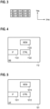
- FIG. 4 schematically illustrates the BS 112.
- the BS 112 includes an interface 1121.
- the interface 1121 may include an analog front end and a digital front end.
- the BS 112 further includes control circuitry 1122, e.g., implemented by means of one or more processors and software.
- control circuitry 1122 e.g., implemented by means of one or more processors and software.
- program code to be executed by the control circuitry 1122 may be stored in a non-volatile memory 1123.
- various functionality may be implemented by the control circuitry 1122, e.g.: transmitting configuration data for WUS transmission in multiple cells; transmitting WUSs; and/or generating WUS including a first part and a second part; etc..
- FIG. 5 schematically illustrates the UE 101.
- the UE 101 includes an interface 1011.
- the interface 1011 may include an analog front end and a digital front end.
- the interface 1011 may include a main receiver and a low-power receiver. Each one of the main receiver and the low-power receiver may include an analog front end and a digital front end, respectively.
- the UE 101 further includes control circuitry 1012, e.g., implemented by means of one or more processors and software.
- the control circuitry 1012 may also be at least partly implemented in hardware.
- program code to be executed by the control circuitry 1012 may be stored in a non-volatile memory 1013.
- control circuitry 1012 may be implemented by the control circuitry 1012, e.g.: receiving configuration data for WUS transmission in multiple cells; receiving WUSs; transitioning the main receiver between an inactive state and an active state; implementing a DRX cycle of the main receiver and/or of the low-power receiver; synchronizing with a BS based on a first part of WUS; channel sensing based on a first part of a WUS and in accordance with the configuration data; performing mobility measurements based on WUSs; etc.
- FIG. 6 illustrates details with respect to the interface 1011 of the UE 101.
- FIG. 6 illustrates aspects with respect to a main receiver 1351 and a low-power receiver 1352.
- the main receiver 1351 and the low-power receiver 1352 are implemented as separate entities. For example, they may be implemented on different chips. For example, they may be implemented in different housings. For example, they may not share a common power supply.
- the scenario FIG. 6 may enable switching off some or all components of the main receiver 1351 when operating the main receiver in inactive state. In the various examples described herein, it may then be possible to receive WUSs using the low-power receiver 1352. Also, the low-power receiver 1352 may be switched between an inactive state and an active state, e.g., according to a DRX cycle.
- the main receiver 1351 may be switched on, the low-power receiver 1352 may be switched off, and vice-versa. As such, the main receiver 1351 and the low-power receiver 1352 may be inter-related in operation (indicated by the arrows in FIG. 6 ).
- FIG. 7 illustrates details with respect to the interface 1011 of the UE 101.
- FIG. 7 illustrates aspects with respect to the main receiver 1351 and the low-power receiver 1352.
- the main receiver 1351 and the low-power receiver 1352 are implemented as a common entity.
- they may be implemented on the common chip, i.e., integrated on a common die.
- they may be implemented in a common housing.
- they may share a common power supply.
- the scenario FIG. 7 may enable a particular low latency for transitioning between reception - e.g., of a WUS - by the low-power receiver 1352 and reception by the main receiver 1351.
- the interface 1011 includes dedicated antennas for the main receiver 1351 and the low-power receiver 1352.
- the WUS may be received by the main receiver 1351 in a low-power state.
- the main receiver 1351 may not be fit to receive ordinary data other than the WUS in the low-power state.
- the main receiver 1351 may transition into a high-power state in which it is fit to receive the ordinary data, e.g., on channel 263, etc.
- FIG. 8 is a flowchart of a method according to various examples.
- FIG. 8 illustrates aspects with respect to constructing or generating the WUS. Specifically, the method according to FIG. 8 may be used for generating a first part of the WUS and/or a second part of the WUS.
- FIG. 8 illustrates aspects with respect to a sequence design of the WUS.
- the base sequence may be a randomly generated set of bits.
- the base sequence may be unique for a UE or a group of UEs.
- the base sequence may be unique for a cell 161-168 of the network 100.
- the base sequence may be selected from the group including: a Zadoff-Chu sequence; a sequence selected from a set of orthogonal or quasi-orthogonal sequences; and a Walsh-Hadamard sequence.
- selecting the particular base sequence or type of base sequence can be subject to sequence design of the WUS.
- setting the sequence length of the base sequence of the WUS can be subject to sequence design of the WUS.
- Selecting the base sequence can be subject to sequence design of the WUS.
- the base sequence selected for the first part of the WUS may be related to a cell 161-168 of the BS transmitting the WUS, e.g., indicative of a cell identity.
- the base sequence of the second part of the WUS may be related to one or more UEs to which the WUS is directed, e.g., based on identities of the UEs.
- different base sequences may be selected for different WUSs - specifically, for the second parts of the WUSs.
- the base sequence may be selected based on an intended recipient of the WUS, i.e., depending on the particular UE 101 to which the WUS is to be transmitted. In other words, it may be possible that the base sequence is uniquely associated with the respective UE 101 as the intended recipient of the WUS. Different UEs may be addressed by different base sequences.
- the base sequence may also be referred to as identity code. Thereby, it may be possible to implement, e.g., the second part of the WUS to be UE-related.
- different base sequences may be selected for different WUSs - specifically, for the first parts of the WUSs.
- the base sequence may be selected based on an originator of the WUS, i.e., depending on the particular BS 112 which transmits the WUS.
- the base sequence is uniquely associated with the respective BS 112 as the originator of the WUS.
- different cells 161-168 may use different WUSs.
- Different BSs or cells 161-168 may be identified by different base sequences.
- the base sequence may also be referred to as identity code.
- a reference signal may be implemented, which is cell-related. This supports WUS-based mobility measurements.
- spreading may be applied to the base sequence, 2002.
- the incoming bit sequence is spread/multiplied with a spreading sequence. This increases the length of the incoming bit sequence by a spreading factor K.
- the resulting bit sequence can be of the same length as the incoming bit sequence times the spreading factor.
- Details of the spreading can be set by a spreading parameter.
- the spreading parameter may specify the spreading sequence, e.g., a length of the spreading sequence or individual bits of the spreading sequence. Setting the spreading parameter can be subject to sequence design of the WUS.
- scrambling may be applied to the spread base sequence, 2003.
- Scrambling may relate to inter-changing or transposing a sequence of the bits of the incoming bit sequence according to one or more rules. Scrambling provides for randomization of the incoming bit sequence. Based on a scrambling code, the original bit sequence can be reproduced at the receiver. Details of the scrambling can be set by a scrambling parameter.
- the scrambling parameter can identify the one or more rules.
- the scrambling parameter can relate to the scrambling code. Setting the scrambling parameter can be subject to sequence design of the WUS.
- a checksum protection parameter may set whether to include or to not include the checksum.
- the checksum protection parameter may set a length of the checksum.
- the checksum protection parameter may set a type of the checksum, e.g., according to different error-correction algorithms, etc.
- the checksum may provide for joint error detection and, optionally, correction capability across the entire length of the WUS, i.e., across multiple parts of the WUS.
- the preamble may include a sequence of preamble bits.
- the sequence of preamble bits may have a specific length.
- the sequence of preamble bits may enable robust identification of the WUS, e.g., even in presence of burst errors, etc.
- Presence of the preamble, length of the preamble, and/or type of the preamble sequence, etc. can be properties that can be set according to a preamble parameter in sequence design of the WUS.
- different cells may rely on different sequence design configurations.
- the sequence design configuration may be indicated by the multi-cell configuration data for multiple cells. This facilitates WUS-based mobility measurements.
- one or more sequence design configurations of the method according to the example of FIG. 8 can be set differently for different parts of the WUS.
- a different sequence design configuration may be set for the first part if compared to the second part of a WUS.
- a more robust sequence design configuration may be set for the first part if compared for the second part; this may include a longer base sequence, and/or a longer checksum, and/or a longer scrambling code; etc.
- This may facilitate reliable reception of the first part, even without previous synchronization and/or channel sensing.
- the second part may then be received based on synchronization and/or channel sensing obtained from the first part; thus, it may not be required to apply such a high level of protection to the second part as for the first part. This reduces overhead.
- FIG. 9 illustrates aspects with respect to the processing of a WUS 4003 received by the low-power receiver 1352.
- the analog front end 1361 outputs a bit sequence corresponding to the WUS 4003 in the baseband to the digital front end 1369.
- the various processing blocks indicated in FIG. 9 - and, as such, also the inter-related processing blocks at the transmitter, cf. FIG. 8 - are optional. It is not required that for all parts of a WUS all processing blocks are executed. Different processing blocks may be executed for different parts of a WUS.
- a symbol-level buffer at the analog front end. Then, based on a demodulator, a symbol sequence in the buffer may be transformed to a bit sequence. This may mark the transition from symbol level to bit level. Bit level processing is then handled in digital domain by the digital front end.
- time-domain and/or frequency-domain processing is employed to identify the WUS 4003.
- respective processing may be with respect to a symbol sequence.
- respective processing may be with respect to a bit sequence.
- processing may be with respect to a symbol sequence if the processing - e.g., correlation - is at the Fast Fourier Transform (FFT) output of the receiver.
- FFT Fast Fourier Transform
- processing may be with respect to a bit sequence if the processing - e.g., correlation - is after the demodulation output, e.g., after M-QAM or PSK output.
- the processing of the WUS by the digital front end 1369 may be comparably simple - e.g., if compared to processing of a paging indicator.
- a PO i.e., allocated to listen to a paging indicator
- the UE is expected to be ready to decode a physical downlink control channel (PDCCH).
- the paging signal may include a temporary identity such as the P-RNTI and a PDCCH checksum which is scrambled with P-RNTI.
- the paging indicator may be transmitted on the PDCCH.
- the PDCCH computation can be energy consuming, especially in MTC.
- the WUS may be transmitted independent of the PDCCH. Dedicated resources may be allocated to the WUS. The WUS may be transmitted prior to the UE accessing the PDCCH. Once the UE has detected a WUS that is assigned to that UE, then the UE may start to decode the PDCCH.
- the WUS can be a robust signal, such that does not operate with higher order modulation. It can be a lower order modulation, such as On-Of-Keying (OOK), BPSK.
- OOK On-Of-Keying
- the WUS may employ a modulation scheme that has low peak to average power ratio property.
- the WUS specifically a part of the WUS related to a UE, can be a random bits and/or sequence signal that can be unique that can be assigned to a UE or group of UEs.
- De-scrambling functionality 1362 then performs de-scrambling.
- de-spreading functionality 1363 is applied.
- a threshold unit 1364 is provided next.
- more reliable cross correlation can be performed. For example, by spreading the base sequence, a longer sequence is obtained for the WUS 4003 transmitted over the air. Longer sequences generally are more robust to false positives when performing the cross correlation.
- FIG. 10 is a signaling diagram.
- FIG. 10 illustrates aspects with respect to communicating between the UE 101 and the BS 112 of the cell 161.
- FIG. 10 relates to a scenario without UE mobility.
- FIG. 10 illustrates aspects with respect to transmitting and/or receiving (communicating) a WUS 4003. According to the various examples described herein, such techniques as described with respect to FIG. 10 may be employed for communicating WUSs 4003.
- FIG. 10 also illustrates aspects with respect to the inter-relationship between communication of a WUS and communication of paging signals and messages 4004, 4005 that may be employed in the various examples described herein.
- configuration data 4001 is communicated.
- the configuration data 4001 is transmitted by the BS 112 and received by the UE 101.
- a respective control message may be communicated on the control channel 262, e.g., PDCCH.
- the control message may be a Layer 2 or Layer 3 control message.
- the control message may be relate to RRC / higher-layer signaling.
- the configuration data 4001 may be broadcasted, e.g., in a system information block of the cell 161; here, PDSCH may be used.
- a mapping index may be used which is indicative of a configuration for WUS transmission selected form a predefined set of candidate transmissions.
- the configuration data 4001 may be for WUS transmission in multiple cells 161 - 168 of the network 100.
- the configuration data may be for WUS transmission in the serving cell 161 of the BS 112 transmitting the configuration data 4001; and at least one further cell 162 - 168.
- the serving cell 161 and the at least one further cell 162 - 168 may define the tracking area 160 of the cellular network.
- the configuration data 4001 may be indicative of support of WUS transmission of each one of the serving cell 161 and the at least one further cell 162 - 168.
- the configuration data 4001 may be indicative of the sequence design configuration of WUS transmission of each one of the serving cell 161 and the at least one further cell 162 - 168. This facilitates cell-specific decoding and/or demodulation.
- the configuration data 4001 may be indicative of a modulation and/or coding scheme (MCS) of the WUS transmission in the serving cell 161 and the at least one further cell 162 - 168.
- MCS modulation and/or coding scheme
- the configuration data 4001 may be indicative of a length of the base sequence used for the WUS transmission in the serving cell 161 and the at least one further cell 162 - 168.
- a user-data message 4002 is communicated.
- the user-data message 4002 may be communicated on the payload channel 263.
- the user-data message 4002 may be communicated along the data connection 189, e.g., as part of a bearer, etc.
- the timer may be implemented at the UE 101.
- the main receiver 1351 of the UE 101 is transitioned into the inactive state 384 from the active state, 3003. This is done in order to reduce the power consumption of the UE 101.
- the timeout duration 201 is an example implementation of a trigger criterion for transitioning into the inactive state 384; other trigger criteria are possible. For example, a connection release message may be communicated.
- the resources 202 may be radio resources defined in a time-frequency grid used for communication with the main receiver 1951; this avoids interference with further UEs communicating with the BS 112.
- the WOs may be arranged in paging frames or in another relationship with POs.
- the BS 112 transmits a WUS 4003, 3004. This may be because there is DL data - e.g., payload data or control data - scheduled for transmission to the UE 101 in a transmit buffer.
- Another trigger criteria for transmitting the WUS 4003 are conceivable. For example, at least a cell-related part of the WUS 4003 may be transmitted repeatedly or, generally, according to a timing pattern.
- the WUS 4003 is received by the UE 101. This WUS transmission is in accordance with the configuration data 4001 for the serving cell 161.
- the main receiver 1351 of the UE 101 is transitioned to the active state, 3005.
- a paging indicator 4004 is transmitted by the BS 112 to the UE 101.
- the paging indicator 4004 is received by the main receiver 1351.
- the paging indicator may be transmitted on channel 262, e.g. PDCCH.
- the paging indicator may include a temporary or static identity of the UE 101.
- the paging indicator or may be indicative of a plurality of UEs, because the indicator may be derived from unique identities of the UEs such as the International Mobile Subscriber Identity (IMSI) or the like in an ambiguous manner.
- IMSI International Mobile Subscriber Identity
- the paging indicator 4004 may include information on a MCS used for communicating a paging message 4005 at 3007.
- the paging message 4005 may be communicated on a shared channel 263, e.g., physical downlink shared channel (PDSCH).
- PDSCH physical downlink shared channel
- the paging indicator 4004 and the paging message 4005 may be communicated on different channels.
- the paging message 4005 may be modulated and encoded according to the MCS indicated by the paging indicator 4004. Thus, it may be required that the UE 101 receives, firstly, the paging indicator 4004 and, secondly, the paging message 4005.
- a data connection 189 is set up between the UE 101 and the BS 112. This may include a random access procedure and a RRC set up.
- a UL or DL user-data message 4002 is communicated using the newly set up data connection 189 at 3009.
- the data connection 189 needs to be re-established. For this reason, the UE 101 operates in idle mode - when no data connection 189 is set up or maintained - during the inactive state 384 of the main receiver 1351.
- the UE 101 operates in idle mode - when no data connection 189 is set up or maintained - during the inactive state 384 of the main receiver 1351.
- other implementations of the particular mode in which the UE 101 operates during the inactive state 384 are conceivable.
- FIG. 11 is a signaling diagram.
- FIG. 11 illustrates aspects with respect to communicating between the UE 101, the BS 112 of the cell 161, and the BS 112 of the cell 162.
- FIG. 11 relates to the scenario with UE mobility.
- FIG. 11 illustrates aspects with respect to communicating a WUS 4003.
- 3051 corresponds to 3001.
- 3052 corresponds to 3002.
- 3053 corresponds to 3003.
- the UE 101 moves from the cell 161 to the cell 162.
- the UE 101 is not able to receive a WUS 4003 transmitted, at 3054, by the BS 112 of the cell 161.
- the UE 101 receives the WUS 4003 transmitted by the BS 112 of the cell 162 at 3055.
- the UE 101 may implement channel sensing for a channel between the BS 112 of the cell 162 and the UE 101; hence, the UE 101 may estimate a corresponding channel quality. This may be facilitated by the WUS 4003 transmitted by the BS 112 of the cell 162 at 3055 including a reference signal for channel sensing.
- a first part of the WUS 4003 communicated at 3055 may include the reference signal. Then, depending on the channel quality, the UE 101 may decide to camp on the cell 162 and continue to receive an information block broadcasted by the BS 112 of the cell 162; or may decide that the channel quality is insufficient and continued to listen for WUS transmission in other cells 163 - 168 (not illustrated in FIG. 11 ).
- the UE 101 checks whether any WUS 4003 can be received from the serving cell 161, e.g., whether a cell-related part of the WUS 4003 transmitted by the BS 112 of the serving cell 161 can be received; only if it is not possible to receive any WUS 4003 from the serving cell 112, the UE 101 may commence with attempting to receive a WUS from another cell 162-168, e.g., again a cell-related part of a WUS 4003.
- the UE 101 may receive a respective reference signal included in a WUS 4003 for each WO from the BS 112 from the originally serving cell 161 (not illustrated in FIGs. 10 and 11 for sake of simplicity), until mobility occurs.
- FIG. 12 illustrates aspects with respect to different modes 301 - 305 in which the UE 101 can operate.
- FIG. 12 also illustrates aspects with respect to association of communication of WUSs and paging signals with the various modes 301 - 305.
- WUSs are communicated in certain operational modes 304, 305 of the UE 101.
- Example implementations of the operational modes 301 - 305 are described, e.g., in 3GPP TS 38.300, e.g., version 15.0.
- a data connection 189 is set up.
- a default bearer and optionally one or more dedicated bearers may be set up between the UE 101 and the network 100.
- the main receiver of the UE 101 may persistently operate in an active state.
- the DRX cycle includes on durations and off durations. During the off durations, the main receiver 1351 is unfit to receive data; an inactive state may be activated.
- the timing of the DRX cycle is synchronized between the UE 101 and the BS 112 such that the BS 112 can align any DL transmission with the on durations of the connected mode DRX cycle.
- the data connection 189 is maintained set-up in mode 302.
- the idle mode 303 is, again, associated with the DRX cycle of the main receiver 1351 of the UE 101.
- the main receiver 1351 is only fit to receive paging indicators and, optionally, paging messages. For example, this may help to restrict the particular bandwidth that needs to be monitored by the main receiver 1351 during the on durations of the DRX cycles in idle mode 303. This may help to further reduce the power consumption - e.g., if compared to the connected mode 302.
- the main receiver 1351 is operated in the active state.
- the low-power receiver 1352 is not required.
- the data connection 189 is maintained between the UE 101 and the network 100.
- respective registry entries may be maintained by the UE 101 and the network 100, e.g., at a core-network mobility node such as the AMF 131.
- Transition into mode 304 may be determined by the inactivity schedule 201.
- mode 304 it would be possible that a further signal which is communicated in response to communicating the WUS directly encodes a user-data message associated with the data connection 189. No random access procedure is required.
- the mode 304 is optional.
- the data connection 189 is not maintained between the UE 101 and the network 100.
- a random access procedure, triggered by paging, may be required (cf. FIG. 10 ).
- the modes 304, 305 are WUS modes 304, 305. Some cells may support mode 304, while other cells may support mode 305, while still further cells may support both mode 304 and mode 305. As a general rule, different cells may support different WUS modes 304, 305.
- both low-power receiver modes 304, 305 implement a DRX cycle of the low-power receiver 1532.
- the WUS 4003 is communicated in accordance with the timing of the DRX cycle.
- FIG. 13 illustrates aspects with respect to switching between the different modes 301 - 305. Furthermore, FIG. 13 illustrates aspects of employing DRX cycles 370. It is possible to employ such techniques in the various examples described herein with respect to communication of WUSs.
- the UE 101 operates in the connected mode 301. This causes a persistent power consumption at a high level, because the main receiver 1351 persistently operates in the active state 381.
- the active state 381 is associated with a certain power consumption.
- the connected mode 302 employing DRX is activated.
- the on durations 371 and the off durations 372 of the main receiver 1351 - selectively operating in the active state 381 and the inactive state 384 - are illustrated.
- the idle mode 303 is activated. This is accompanied by releasing the data connection 189.
- the idle mode 303 employs a DRX cycle including on durations 371 and off durations 372.
- the on durations 371 in mode 303 are associated with a lower power consumption if compared to the on durations 371 in connected mode 302, because in the idle mode 303, the capability of the main receiver 1351, now operating in the active state 382, can be reduced if compared to the connected mode 302.
- the main receiver 1351 only expects reception of paging signals.
- the on durations 371 are aligned with POs.
- the idle mode 305 is activated.
- the main receiver 1351 is persistently transitioned from the active states 381, 382 to the inactive state 384.
- a DRX cycle 370 is again implemented including on durations 371 and off durations 372 according to a DRX cycle length 375; here the on durations 371 are aligned with WOs.
- the DRX cycle is implemented by switching the low-power receiver 1352 between the active state 383 and the inactive state 384 (dashed line in FIG. 13 ).
- the various states 381 - 384 are examples only. For illustration, it would be possible that the main receiver is not transitioned into the fully inactive state 384 when in DRX connected mode 302; rather, in the OFF durations 372, an intermediate state between 381 and 384 could be assumed.
- FIG. 14 illustrates aspects with respect to a WUS 700.
- the WUS 700 includes a first part 711 and a second part 712.
- the first and second parts 711, 712 occupy the same frequency and are transmitted in immediate succession.
- the first part 711 may be related to the cell 161-168 associated with the BS 112 transmitting the WUS 700.
- the second part 712 may be related to one or more UEs 101 to which the WUS 700 is addressed.
- the second part 712 is optional.
- the first part 711 and the second part 712 may share a common checksum.
- the checksum may be based, both, on data of the first part 711 and data of the second part 712. This reduces overhead.
- the first part 711 of the WUS 700 includes a synchronization signal 721 for time-frequency synchronization of the BS 112 and the UE 101.
- Properties of the synchronization signal 721 may be indicated by the configuration data 4001 for multiple cells 161-168.
- the first part 711 of the WUS 700 may also include a reference signal 723 for channel sensing of the channel between the BS 112 and the UE 101.
- Properties of the reference signal - e.g., a signal form symbol sequence, transmit power, etc. - may be indicated by the configuration data 4001 for multiple cells 161-168.
- the first part 711 of the WUS 700 includes a cell identity 722 of a cell 161-168 associated with the BS 112 transmitting the WUS 700.
- the cell identity 722 may be encoded into the synchronization signal 721 and/or the reference signal 723. Based on the cell identity, it is possible to track mobility of the UE 101.
- the identifier used for indicating the cell identity may be in accordance with a respective identifier included in the configuration data 4001.
- the synchronization signal 721, the reference signal 723, and the cell identity 722 are all not specific to the UE 101 as intended recipient of the WUS 700.
- the first part 711 is related to the cell of the BS 112 transmitting the WUS 700; rather than to the UE 101 as intended recipient. This is different for the second part 712. This facilitates implementing mobility measurements such as channel sensing at a given UE based on the first part 711.
- Illustrated in FIG. 14 is a scenario in which the second part 712 of the WUS 700 includes an identity 731 of one or more UEs. This helps to address individual UEs or a group of UEs in connection with a potential subsequent paging signal 4004. As, such the second part 712 may be related to one or more UEs.
- first part 711 of the WUS 700 For generating the first part 711 of the WUS 700, techniques as described in connection with FIG. 8 can be employed. Likewise, for generating the second part 712 of the WUS 700, techniques described in connection with FIG. 8 may be employed. Different sequence design configurations may be selected for the different parts 711, 712. For example, a cell-specific base sequence may be selected when generating the first part 711; while a UE-specific base sequence may be selected when generating the second part 712. It would be possible that the length of the base sequence, the number of CRC bits, the spreading factor, the particular type of sequence generator used, etc. - or generally, the sequence design - is selected differently for the first part 711 and for the second part 712.
- a scenario is illustrated in which a distinct synchronization signal 721 and a distinct reference signal 723 is included in the WUS 700.
- the preamble - i.e., the first part 711 of the WUS 700 - may consist of a reference signal only, which provides means for synchronization and channel sensing.
- the multi-cell configuration data 4001 may cover the first part 711 and/or the second part 712. Where the multi-cell configuration data 4001 is primarily used for mobility measurements, it may be sufficient to cover the first part 411, to limit control signaling overhead.
- FIG. 15 is a flowchart of a method according to various examples.
- the method according to FIG. 15 could be executed by the control circuitry 1122 of the BS 112 (cf. FIG. 4 ).
- configuration data is transmitted, e.g., the configuration data 4001 (cf. FIG. 10 and FIG. 11 ).
- the configuration data is transmitted for WUS transmission in the cell associated with the transmitting BS; as well as for WUS transmission in at least one further cell of the respective cellular network.
- the configuration data may be broadcasted, e.g., as part of an information block. It would also be possible that the configuration data is transmitted in a UE-specific control message, e.g., using a respective control channel between the BS and the UE.
- an index mapping with a plurality of candidate configurations may be implemented, to thereby reduce overhead.
- the configuration data may be selectively for one or more parts of a multi-part WUS.
- the configuration data may cover any cell-related part of a WUS; but may not cover any UE-related part of the WUS.
- a WUS is transmitted, in accordance with any configuration indicated by the configuration data.
- a two-part WUS including a first part related to the respective cell and the second part related to the UE being paged may be transmitted (cf. FIG. 14 ).
- block 2102 is optional.
- the transmitted WUS may not include a part related to a UE; but may comprise a cell-related part.
- the cell-related part may include a reference signal.
- any receiving UE - which is not necessarily being paged - may be able to track mobility by listening for the respective WUS transmission. Mobility measurements including channel sensing are facilitated.
- FIG. 16 is a flowchart of a method according to various examples.
- the method according to FIG. 16 may be executed by the control circuitry 1012 of the UE 101.
- configuration data is received.
- block 2111 is inter-related with block 2101 (cf. FIG. 15 ).
- the UE listens for a WUS transmission. This may be in accordance with the DRX cycle of the respective UE. Furthermore, listening for the WUS may be in accordance with the configuration data. Specifically, it would be possible to listen for WUS transmission of a plurality of cells for which the configuration data is indicative of support of WUS transmission and optionally the configuration of the associated WUS transmission.
- a two-part WUS is employed, wherein the WUS includes a cell-related first part and a UE-related second part.
- the WUS includes a cell-related first part and a UE-related second part.
- the UEs may make different use of any WUSs received at block 2112 for various cells. Mobility measurements can be supported. A respective scenario is illustrated in connection with FIG. 17 .
- the UE 101 listens for a WUS transmission in the serving cell 161.
- the UE 101 attempts to receive and process - e.g., in accordance with the techniques described in FIG. 9 - a WUS 700, 4003 transmitted by the BS 112 of the serving cell.
- the UE 101 may attempt to receive a cell-related first part 711 of the WUS 700, 4003, at block 2122.
- This first part 711 may enable the UE 101 to perform mobility measurements, e.g., to identify whether mobility has occurred or whether the UE 101 is still camping on the serving cell 161.
- the UE 101 may also listen for a UE-related second part 712 of the WUS 700, 4003; thereby, wakeup of the UE 101 may be facilitated, e.g., to establish the data connection 189 and preparation of transmission of a user-data message 4002.
- a WUS has been received, then, at block 2124, it is checked whether the UE is being paged by the network 100. This may involve analyzing a UE-related second part 712 of the WUS 700, 4003. Alternatively or additionally, a paging signal and/or a paging message may be received (cf. FIGs. 10 and 11 ).
- the UE If the UE is not being paged, then, at 2125, the low-power receiver 1352 is deactivated again, to reduce power consumption. Otherwise, at block 2126, the UE continues to setup the data connection 189.
- the measurement of neighbor cells commences in accordance with the configuration data 4001. Specifically, in the illustrated example, the method commences at block 2127.
- a current cell 162 - 168 is selected based on the configuration data 4001.
- the configuration data 4001 may include a cell list which is indicative of the identities of a plurality of further cells 162 - 168 for which configuration of the WUS transmission is provided.
- the cells 162 - 168 may form a tracking area (cf. FIG. 2 ).
- the UE continues to listen for a WUS transmission of the current selected cell 162 - 168. Again, as already explained in connection with block 2122, this may involve listening for a cell-related first part 711 of the WUS 700, 4003 (cf. FIG. 14 ). This may help to implement mobility measurements, e.g., to estimate a channel quality of a channel between the UE and the BS 112 of the current selected cell 162 - 168.
- Listening for the WUS in the current cell in block 2128 can be implemented as explained in connection with block 2112 of FIG. 16 .
- listening for the WUS in the current cell in block 2128 can be in accordance with the configuration data previously received.
- the UE may listen in particular time-frequency resources indicated by the configuration data.
- the time-frequency resources may be indicated by means of a repetitive schedule.
- a timing reference may be provided by referencing to control signals such as paging signals.
- the timing reference may be provided with respect to POs.
- Any decoding attempts may be implemented in accordance with a sequence design configuration that may also be indicated by the configuration data.
- block 2129 it is checked whether a WUS - e.g., a cell-related part thereof or any WUS at all - has been received in the current cell. If this is not the case, then block 2127 is re-executed, and a new current cell is selected. However, if a WUS has been received at block 2128, then, block 2130 is executed.
- a WUS e.g., a cell-related part thereof or any WUS at all - has been received in the current cell.
- a channel quality of the channel between the UE 101 and the BS 112 of the current cell 162 - 168 is estimated and compared with a threshold. Based on this threshold comparison, it can be checked whether the channel quality is sufficient and, thus, the UE 101 can be considered to be in-coverage of the current cell 162 -168. This facilitates the mobility measurements to track mobility of the UE 101.
- block 2130 If at block 2130 it is checked that the channel quality is insufficient, then block 2127 is re-executed and a new current cell is selected. Otherwise, block 2131 is executed. At block 2131, the UE 101 continues to listen for system information broadcasted by the current cell.
- the WUS includes a first part and a second part.
- the second part may be related to one or more UEs; while the first part may implement preamble functionality to avoid robust reception of the second part.
- This preamble functionality may include time-domain and/or frequency domain synchronization, mobility detection based on cell identity, and/or channel sensing.
- the first part may be the same for all UEs served by the BS of the respective cell, i.e., may be cell related.
- the first part may include information related to the cell identity. For instance this could be the serving cell identity, or a sequence that is indicative of the serving cell identity.
- the first part is typically the same for all the UEs within the serving cell, i.e. it is cell specific.
- the first part is transmitted with the same periodicity as WOs.
- the second part of the WUS may only be transmitted by the BS if there is DL data queued for transmission to a respective UE. If the first part is designed such that it can also be used for synchronization purposes then second part can become somehow shorter, but still can be detected non-coherently. It also implies that there is a case where the WUS with only first-part transmission, e.g. the second part does not need to be transmitted periodically. In this case, a given UE receives the first part and use it for mobility measurements.
- the UE listens for WUS transmission, i.e. monitors the channel for WUS in some pre-determined WOs, it first check the cell identity indicator by decoding the first part determines and the signal strength of the serving cell. If the level of the signal is above a certain level determined by received signal strength and the cell identity indicator is correct, as well as possible some other signal performance criterions, then the UE continues to check for the existence of the second part, to see whether wakeup is demanded by the network. If the UE detects the second part carrying a certain information related to it, it then announces that a WUS is detected and continues to receive paging signals and/or paging messages.
- the channel sensing may in general not need a separate signal, but could be done using synchronization signal and/or reference signal.
- the combination of both signals can improve the channel sensing measurement accuracy.
- the base-station may need to inform the UE on the relative power different between these two signals, if they are transmitted separately.
Landscapes
- Engineering & Computer Science (AREA)
- Signal Processing (AREA)
- Computer Networks & Wireless Communication (AREA)
- Mobile Radio Communication Systems (AREA)
Claims (14)
- Procédé de fonctionnement d'un noeud d'accès (112) d'une sous-zone (161) d'un réseau de communication (100), comprenant :- l'émission de données de configuration (4001) pour l'émission de signaux de réveil dans la sous-zone (161) et dans au moins une autre sous-zone (162-168) du réseau de communication (100),dans lequel l'autre sous-zone (162-168) est une sous-zone voisine (162-168),dans lequel les données de configuration (4001) sont pour une première partie (711) de signaux de réveil (700, 711, 712, 4003) de l'émission de signaux de réveil dans la sous-zone (161) et dans au moins une autre sous-zone (162-168) du réseau de communication (100), etdans lequel la première partie (711) est constituée par un signal de synchronisation.
- Procédé de fonctionnement d'un terminal (101), comprenant :- la réception, en provenance d'un noeud d'accès (112) d'une sous-zone (161) d'un réseau de communication (100), de données de configuration (4001) pour l'émission de signaux de réveil dans la sous-zone (161) et dans au moins une autre sous-zone (162-168) du réseau de communication (100),dans lequel l'autre sous-zone (162-168) est une sous-zone voisine (162-168),dans lequel les données de configuration (4001) sont pour une première partie (711) de signaux de réveil (700, 711, 712, 4003) de l'émission de signaux de réveil dans la sous-zone (161) et dans au moins une autre sous-zone (162-168) du réseau de communication (100), etdans lequel la première partie (711) est constituée par un signal de synchronisation.
- Procédé selon la revendication 2, comprenant en outre :- conformément aux données de configuration : l'écoute de l'émission de signaux de réveil dans l'au moins une autre sous-zone (162-168).
- Procédé selon la revendication 3, comprenant en outre :- sur la base de ladite écoute : l'estimation d'une qualité de canal d'un canal entre le terminal (101) et un autre noeud d'accès (112) de l'au moins une autre sous-zone (162-168), dans lequel l'émission de signaux de réveil dans l'au moins une autre sous-zone (162-168) comprend un signal de référence.
- Procédé selon l'une quelconque des revendications 1 à 4,dans lequel la première partie (711) de signaux de réveil (700, 711, 712, 4003) émis dans la sous-zone (161) est rapportée à la sous-zone (161),dans lequel la première partie (711) de signaux de réveil (700, 711, 712, 4003) émis dans l'au moins une autre sous-zone (162-168) est rapportée à l'au moins une autre sous-zone.
- Procédé selon l'une quelconque des revendications 1 à 5,
dans lequel au moins certains des signaux de réveil de l'émission de signaux de réveil dans la sous-zone et dans l'au moins une autre sous-zone comprennent une seconde partie qui est rapportée à un terminal ou à plusieurs terminaux. - Procédé selon l'une quelconque des revendications précédentes,
dans lequel les données de configuration (4001) sont indicatives du support de l'émission de signaux de réveil par la sous-zone (161) et par l'au moins une autre sous-zone (162-168). - Procédé selon l'une quelconque des revendications précédentes,dans lequel les données de configuration (4001) sont indicatives de ressources temps-fréquence(s) utilisées pour l'émission de signaux de réveil dans la sous-zone (161) et dans l'au moins une autre sous-zone (162-168),dans lequel les données de configuration (4001) sont en option indicatives d'une planification des ressources temps-fréquence(s).
- Procédé selon la revendication 8,dans lequel la planification est indicative d'un motif temporel des ressources temps-fréquence(s), et/oudans lequel la planification est indicative d'un motif de fréquence(s) des ressources temps-fréquence(s).
- Procédé selon la revendication 9,
dans lequel au moins un motif parmi le motif temporel et le motif de fréquence(s) varie entre la sous-zone (161) et l'au moins une autre sous-zone (162-168). - Procédé selon l'une quelconque des revendications précédentes,
dans lequel la sous-zone (161) et l'au moins une autre sous-zone (162-168) définissent une zone de suivi (160) du réseau de communication (100). - Procédé selon l'une quelconque des revendications précédentes,dans lequel les données de configuration (4001) sont indicatives d'au moins une configuration parmiune configuration pour l'émission de signaux de réveil sélectionnée parmi un ensemble prédéfini de configurations candidates, etune configuration de conception de séquence(s) de l'émission de signaux de réveil par la sous-zone (161) et par l'au moins une autre sous-zone (162-168).
- Terminal (101), comprenant un circuit de commande configuré pour réaliser :- la réception, en provenance d'un noeud d'accès (112) d'une sous-zone (161) d'un réseau de communication (100), de données de configuration (4001) pour l'émission de signaux de réveil dans la sous-zone (161) et dans au moins une autre sous-zone (162-168) du réseau de communication (100),dans lequel l'autre sous-zone (162-168) est une sous-zone voisine (162-168),dans lequel les données de configuration (4001) sont pour une première partie (711) de signaux de réveil (700, 711, 712, 4003) de l'émission de signaux de réveil dans la sous-zone (161) et dans au moins une autre sous-zone (162-168) du réseau de communication (100), etdans lequel la première partie (711) est constituée par un signal de synchronisation.
- Noeud d'accès (112) d'une sous-zone (161) d'un réseau de communication (100), comprenant un circuit de commande configuré pour réaliser :- l'émission de données de configuration (4001) pour l'émission de signaux de réveil dans la sous-zone (161) et dans au moins une autre sous-zone (162-168) du réseau de communication (100),dans lequel l'autre sous-zone (162-168) est une sous-zone voisine (162-168),dans lequel les données de configuration (4001) sont pour une première partie (711) de signaux de réveil (700, 711, 712, 4003) de l'émission de signaux de réveil dans la sous-zone (161) et dans au moins une autre sous-zone (162-168) du réseau de communication (100), etdans lequel la première partie (711) est constituée par un signal de synchronisation.
Applications Claiming Priority (2)
| Application Number | Priority Date | Filing Date | Title |
|---|---|---|---|
| SE1830028 | 2018-01-26 | ||
| PCT/EP2019/051775 WO2019145437A1 (fr) | 2018-01-26 | 2019-01-24 | Configuration de signal de réveil multi-cellule |
Publications (2)
| Publication Number | Publication Date |
|---|---|
| EP3744129A1 EP3744129A1 (fr) | 2020-12-02 |
| EP3744129B1 true EP3744129B1 (fr) | 2024-01-03 |
Family
ID=65237029
Family Applications (1)
| Application Number | Title | Priority Date | Filing Date |
|---|---|---|---|
| EP19702056.3A Active EP3744129B1 (fr) | 2018-01-26 | 2019-01-24 | Configuration de signal de réveil multi-cellule |
Country Status (4)
| Country | Link |
|---|---|
| US (1) | US11330522B2 (fr) |
| EP (1) | EP3744129B1 (fr) |
| CN (1) | CN111656823B (fr) |
| WO (1) | WO2019145437A1 (fr) |
Families Citing this family (16)
| Publication number | Priority date | Publication date | Assignee | Title |
|---|---|---|---|---|
| AU2018418717A1 (en) | 2018-04-11 | 2020-11-26 | Guangdong Oppo Mobile Telecommunications Corp., Ltd. | Method and device for transmitting power saving signal |
| CN110740496B (zh) * | 2018-07-20 | 2022-08-05 | 珠海市魅族科技有限公司 | 时间同步的方法、装置及时间同步的指示方法、指示装置 |
| US11764932B2 (en) * | 2019-08-30 | 2023-09-19 | Qualcomm Incorporated | Time-dependent adaptation of a wake-up signal configuration |
| JP7324945B2 (ja) | 2019-10-02 | 2023-08-10 | ソニーグループ株式会社 | ウェイクアップ信号送信のためのリソースを構成するための方法、関連する無線デバイス、及び関連するネットワークノード |
| CN115843018A (zh) * | 2021-08-30 | 2023-03-24 | 华为技术有限公司 | 一种通信方法、装置及系统 |
| CN116209032A (zh) * | 2021-11-30 | 2023-06-02 | 华为技术有限公司 | 一种通信方法及设备 |
| WO2023108576A1 (fr) * | 2021-12-17 | 2023-06-22 | Oppo广东移动通信有限公司 | Procédé et appareil de communication |
| WO2023159468A1 (fr) * | 2022-02-25 | 2023-08-31 | Oppo广东移动通信有限公司 | Procédé de transmission d'informations, dispositif terminal et dispositif de réseau |
| WO2023208950A1 (fr) * | 2022-04-29 | 2023-11-02 | Sony Group Corporation | Signaux de référence de faible puissance pour resélection de cellule |
| CN117098210A (zh) * | 2022-05-11 | 2023-11-21 | 维沃移动通信有限公司 | 监听方法、装置、终端、网络侧设备及可读存储介质 |
| CN117295103A (zh) * | 2022-06-16 | 2023-12-26 | 华为技术有限公司 | 通信方法和装置 |
| WO2024015894A1 (fr) * | 2022-07-14 | 2024-01-18 | Intel Corporation | Déclenchement de transmission à l'aide d'un récepteur de réveil à faible puissance séparé |
| CN117560749A (zh) * | 2022-08-03 | 2024-02-13 | 维沃移动通信有限公司 | 唤醒信号的同步源的确定方法、终端及网络侧设备 |
| WO2024036614A1 (fr) * | 2022-08-19 | 2024-02-22 | Huawei Technologies Co., Ltd. | Procédés, appareil et systèmes de réveil de faible complexité et de faible puissance d'un dispositif électronique |
| CN117675096A (zh) * | 2022-08-26 | 2024-03-08 | 华为技术有限公司 | 通信方法和相关装置 |
| WO2024077610A1 (fr) * | 2022-10-14 | 2024-04-18 | 北京小米移动软件有限公司 | Procédé et appareil de mesure, dispositif et support de stockage lisible |
Citations (1)
| Publication number | Priority date | Publication date | Assignee | Title |
|---|---|---|---|---|
| WO2019096912A1 (fr) * | 2017-11-15 | 2019-05-23 | Sony Corporation | Réduction de la consommation d'énergie pour tous les types de dispositif terminal |
Family Cites Families (10)
| Publication number | Priority date | Publication date | Assignee | Title |
|---|---|---|---|---|
| US6360327B1 (en) * | 1999-03-12 | 2002-03-19 | Compaq Information Technologies Group, L.P. | System with control registers for managing computer legacy peripheral devices using an advanced configuration power interface software power management system |
| US8699509B2 (en) | 2008-10-29 | 2014-04-15 | Qualcomm Incorporated | Methods and systems for diversity idle mode in a mobile station |
| US20100317374A1 (en) * | 2009-06-11 | 2010-12-16 | Yaron Alpert | Apparatus for and method of managing paging interval access on a mobile station |
| EP2424290B1 (fr) * | 2010-08-24 | 2015-02-25 | Alcatel Lucent | Groupage d'un sous-ensemble de cellules dans un réseau de télécommunication sans fil |
| US10057847B2 (en) * | 2012-09-14 | 2018-08-21 | Telefonaktiebolaget Lm Ericsson (Publ) | QOS-based cooperative scheduling for handling of data traffic |
| US9854515B2 (en) * | 2012-12-07 | 2017-12-26 | Avago Technologies General Ip (Singapore) Pte. Ltd. | Energy saving operations for wireless networks |
| US10004085B2 (en) * | 2014-01-21 | 2018-06-19 | Telefonaktiebolaget Lm Ericsson (Publ) | Scheduling for heterogeneous networks |
| EP2941063B1 (fr) * | 2014-04-29 | 2017-11-01 | NTT Docomo, Inc. | Découverte et activation de petites cellules assistées de macrocellules |
| US10481588B2 (en) | 2017-01-24 | 2019-11-19 | The Boeing Company | Configurable vehicle seat and method therefor |
| CN107484128B (zh) * | 2017-08-14 | 2020-03-31 | 南方电网科学研究院有限责任公司 | 基于rts/cts协议的通信方法及装置、计算机设备及存储介质 |
-
2019
- 2019-01-24 US US16/957,852 patent/US11330522B2/en active Active
- 2019-01-24 CN CN201980009604.3A patent/CN111656823B/zh active Active
- 2019-01-24 EP EP19702056.3A patent/EP3744129B1/fr active Active
- 2019-01-24 WO PCT/EP2019/051775 patent/WO2019145437A1/fr unknown
Patent Citations (1)
| Publication number | Priority date | Publication date | Assignee | Title |
|---|---|---|---|---|
| WO2019096912A1 (fr) * | 2017-11-15 | 2019-05-23 | Sony Corporation | Réduction de la consommation d'énergie pour tous les types de dispositif terminal |
Also Published As
| Publication number | Publication date |
|---|---|
| US11330522B2 (en) | 2022-05-10 |
| CN111656823B (zh) | 2023-11-03 |
| WO2019145437A1 (fr) | 2019-08-01 |
| EP3744129A1 (fr) | 2020-12-02 |
| CN111656823A (zh) | 2020-09-11 |
| US20210022077A1 (en) | 2021-01-21 |
Similar Documents
| Publication | Publication Date | Title |
|---|---|---|
| EP3744129B1 (fr) | Configuration de signal de réveil multi-cellule | |
| EP3704899B1 (fr) | Signal de réveil en deux parties | |
| US11184852B2 (en) | Wake-up signal with reconfigurable sequence design | |
| US11770769B2 (en) | Wake-up signal transmission on relaying links | |
| EP3580995B1 (fr) | Radiomessagerie dispensée par relais | |
| US20210185611A1 (en) | Support of multiple wake-up-signal-related capabilities | |
| US20210022078A1 (en) | Wake-up transmission on a separate carrier | |
| US11665667B2 (en) | Flexible paging procedure |
Legal Events
| Date | Code | Title | Description |
|---|---|---|---|
| STAA | Information on the status of an ep patent application or granted ep patent |
Free format text: STATUS: UNKNOWN |
|
| STAA | Information on the status of an ep patent application or granted ep patent |
Free format text: STATUS: THE INTERNATIONAL PUBLICATION HAS BEEN MADE |
|
| PUAI | Public reference made under article 153(3) epc to a published international application that has entered the european phase |
Free format text: ORIGINAL CODE: 0009012 |
|
| STAA | Information on the status of an ep patent application or granted ep patent |
Free format text: STATUS: REQUEST FOR EXAMINATION WAS MADE |
|
| 17P | Request for examination filed |
Effective date: 20200706 |
|
| AK | Designated contracting states |
Kind code of ref document: A1 Designated state(s): AL AT BE BG CH CY CZ DE DK EE ES FI FR GB GR HR HU IE IS IT LI LT LU LV MC MK MT NL NO PL PT RO RS SE SI SK SM TR |
|
| AX | Request for extension of the european patent |
Extension state: BA ME |
|
| DAV | Request for validation of the european patent (deleted) | ||
| DAX | Request for extension of the european patent (deleted) | ||
| STAA | Information on the status of an ep patent application or granted ep patent |
Free format text: STATUS: EXAMINATION IS IN PROGRESS |
|
| 17Q | First examination report despatched |
Effective date: 20210607 |
|
| RAP3 | Party data changed (applicant data changed or rights of an application transferred) |
Owner name: SONY GROUP CORPORATION |
|
| GRAP | Despatch of communication of intention to grant a patent |
Free format text: ORIGINAL CODE: EPIDOSNIGR1 |
|
| STAA | Information on the status of an ep patent application or granted ep patent |
Free format text: STATUS: GRANT OF PATENT IS INTENDED |
|
| INTG | Intention to grant announced |
Effective date: 20230721 |
|
| GRAS | Grant fee paid |
Free format text: ORIGINAL CODE: EPIDOSNIGR3 |
|
| GRAA | (expected) grant |
Free format text: ORIGINAL CODE: 0009210 |
|
| STAA | Information on the status of an ep patent application or granted ep patent |
Free format text: STATUS: THE PATENT HAS BEEN GRANTED |
|
| AK | Designated contracting states |
Kind code of ref document: B1 Designated state(s): AL AT BE BG CH CY CZ DE DK EE ES FI FR GB GR HR HU IE IS IT LI LT LU LV MC MK MT NL NO PL PT RO RS SE SI SK SM TR |
|
| REG | Reference to a national code |
Ref country code: GB Ref legal event code: FG4D |
|
| REG | Reference to a national code |
Ref country code: DE Ref legal event code: R096 Ref document number: 602019044400 Country of ref document: DE |
|
| REG | Reference to a national code |
Ref country code: CH Ref legal event code: EP |
|
| REG | Reference to a national code |
Ref country code: IE Ref legal event code: FG4D Ref country code: NL Ref legal event code: FP |
|
| PGFP | Annual fee paid to national office [announced via postgrant information from national office to epo] |
Ref country code: NL Payment date: 20240220 Year of fee payment: 6 |
|
| REG | Reference to a national code |
Ref country code: LT Ref legal event code: MG9D |
|
| PG25 | Lapsed in a contracting state [announced via postgrant information from national office to epo] |
Ref country code: ES Free format text: LAPSE BECAUSE OF FAILURE TO SUBMIT A TRANSLATION OF THE DESCRIPTION OR TO PAY THE FEE WITHIN THE PRESCRIBED TIME-LIMIT Effective date: 20240103 |
|
| PG25 | Lapsed in a contracting state [announced via postgrant information from national office to epo] |
Ref country code: ES Free format text: LAPSE BECAUSE OF FAILURE TO SUBMIT A TRANSLATION OF THE DESCRIPTION OR TO PAY THE FEE WITHIN THE PRESCRIBED TIME-LIMIT Effective date: 20240103 |
|
| PGFP | Annual fee paid to national office [announced via postgrant information from national office to epo] |
Ref country code: DE Payment date: 20240123 Year of fee payment: 6 Ref country code: GB Payment date: 20240221 Year of fee payment: 6 |
|
| P01 | Opt-out of the competence of the unified patent court (upc) registered |
Effective date: 20240329 |