EP3738352B1 - Dispositif et procédé de communication sans fil - Google Patents
Dispositif et procédé de communication sans fil Download PDFInfo
- Publication number
- EP3738352B1 EP3738352B1 EP19700026.8A EP19700026A EP3738352B1 EP 3738352 B1 EP3738352 B1 EP 3738352B1 EP 19700026 A EP19700026 A EP 19700026A EP 3738352 B1 EP3738352 B1 EP 3738352B1
- Authority
- EP
- European Patent Office
- Prior art keywords
- wireless communications
- infrastructure equipment
- communications device
- wireless
- network
- Prior art date
- Legal status (The legal status is an assumption and is not a legal conclusion. Google has not performed a legal analysis and makes no representation as to the accuracy of the status listed.)
- Active
Links
- 238000004891 communication Methods 0.000 title claims description 182
- 238000000034 method Methods 0.000 title claims description 23
- 230000005540 biological transmission Effects 0.000 claims description 14
- 235000008694 Humulus lupulus Nutrition 0.000 claims description 7
- 230000011664 signaling Effects 0.000 description 9
- 238000010586 diagram Methods 0.000 description 7
- 238000005516 engineering process Methods 0.000 description 6
- 238000013459 approach Methods 0.000 description 4
- 230000008901 benefit Effects 0.000 description 3
- 238000012545 processing Methods 0.000 description 3
- 101150096310 SIB1 gene Proteins 0.000 description 2
- 101150039363 SIB2 gene Proteins 0.000 description 2
- 230000007774 longterm Effects 0.000 description 2
- CIWBSHSKHKDKBQ-JLAZNSOCSA-N Ascorbic acid Chemical compound OC[C@H](O)[C@H]1OC(=O)C(O)=C1O CIWBSHSKHKDKBQ-JLAZNSOCSA-N 0.000 description 1
- 230000003213 activating effect Effects 0.000 description 1
- 238000007792 addition Methods 0.000 description 1
- 230000008859 change Effects 0.000 description 1
- 230000001010 compromised effect Effects 0.000 description 1
- 238000001514 detection method Methods 0.000 description 1
- 238000011161 development Methods 0.000 description 1
- 230000004069 differentiation Effects 0.000 description 1
- 230000000694 effects Effects 0.000 description 1
- 239000000835 fiber Substances 0.000 description 1
- 238000012986 modification Methods 0.000 description 1
- 230000004048 modification Effects 0.000 description 1
- 230000003287 optical effect Effects 0.000 description 1
- 230000008569 process Effects 0.000 description 1
- QGFSVPWZEPKNDV-BRTFOEFASA-N ranp Chemical compound C([C@H]1C(=O)NCC(=O)NCC(=O)N[C@@H](CCCNC(N)=N)C(=O)N[C@H](C(=O)N[C@@H](CC(O)=O)C(=O)N[C@@H](CCCNC(N)=N)C(=O)N[C@H](C(NCC(=O)N[C@@H](C)C(=O)N[C@@H](CCC(N)=O)C(=O)N[C@@H](CO)C(=O)NCC(=O)N[C@@H](CC(C)C)C(=O)NCC(=O)N[C@@H](CSSC[C@@H](C(=O)N1)NC(=O)[C@H](CO)NC(=O)[C@H](CO)NC(=O)[C@H](CCCNC(N)=N)NC(=O)[C@H](CCCNC(N)=N)NC(=O)[C@H](CC(C)C)NC(=O)[C@@H](N)CO)C(=O)N[C@@H](CC(N)=O)C(=O)N[C@@H](CO)C(=O)N[C@@H](CC=1C=CC=CC=1)C(=O)N[C@@H](CCCNC(N)=N)C(=O)N[C@@H](CC=1C=CC(O)=CC=1)C(O)=O)=O)[C@@H](C)CC)[C@@H](C)CC)C1=CC=CC=C1 QGFSVPWZEPKNDV-BRTFOEFASA-N 0.000 description 1
- 239000004065 semiconductor Substances 0.000 description 1
Images


Classifications
-
- H—ELECTRICITY
- H04—ELECTRIC COMMUNICATION TECHNIQUE
- H04W—WIRELESS COMMUNICATION NETWORKS
- H04W48/00—Access restriction; Network selection; Access point selection
- H04W48/08—Access restriction or access information delivery, e.g. discovery data delivery
- H04W48/10—Access restriction or access information delivery, e.g. discovery data delivery using broadcasted information
-
- H—ELECTRICITY
- H04—ELECTRIC COMMUNICATION TECHNIQUE
- H04W—WIRELESS COMMUNICATION NETWORKS
- H04W16/00—Network planning, e.g. coverage or traffic planning tools; Network deployment, e.g. resource partitioning or cells structures
- H04W16/24—Cell structures
- H04W16/28—Cell structures using beam steering
-
- H—ELECTRICITY
- H04—ELECTRIC COMMUNICATION TECHNIQUE
- H04W—WIRELESS COMMUNICATION NETWORKS
- H04W84/00—Network topologies
- H04W84/02—Hierarchically pre-organised networks, e.g. paging networks, cellular networks, WLAN [Wireless Local Area Network] or WLL [Wireless Local Loop]
- H04W84/04—Large scale networks; Deep hierarchical networks
- H04W84/042—Public Land Mobile systems, e.g. cellular systems
- H04W84/047—Public Land Mobile systems, e.g. cellular systems using dedicated repeater stations
-
- H—ELECTRICITY
- H04—ELECTRIC COMMUNICATION TECHNIQUE
- H04W—WIRELESS COMMUNICATION NETWORKS
- H04W88/00—Devices specially adapted for wireless communication networks, e.g. terminals, base stations or access point devices
- H04W88/02—Terminal devices
- H04W88/04—Terminal devices adapted for relaying to or from another terminal or user
-
- H—ELECTRICITY
- H04—ELECTRIC COMMUNICATION TECHNIQUE
- H04W—WIRELESS COMMUNICATION NETWORKS
- H04W88/00—Devices specially adapted for wireless communication networks, e.g. terminals, base stations or access point devices
- H04W88/08—Access point devices
- H04W88/085—Access point devices with remote components
Definitions
- the present disclosure relates to a wireless communication device configured to act as remote node to form cells of a radio network part of a wireless communications network and a method of the same.
- Third and fourth generation mobile telecommunication systems such as those based on the 3GPP defined UMTS and Long Term Evolution (LTE) architecture, are able to support more sophisticated services than simple voice and messaging services offered by previous generations of mobile telecommunication systems.
- LTE Long Term Evolution
- a user is able to enjoy high data rate applications such as mobile video streaming and mobile video conferencing that would previously only have been available via a fixed line data connection.
- the demand to deploy such networks is therefore strong and the coverage area of these networks, i.e. geographic locations where access to the networks is possible, may be expected to increase ever more rapidly.
- the deployment of remote nodes which form cells of a wireless communications network can present a technical problem where a connection to a core network part of a wireless communications network is required. If the connection is provided using a wireless access interface which is provided by the radio network then new technical problems to be solved can be created.
- WO 2016/073984 A2 (INTERDIGITAL PATENT HOLDINGS [US]) 12 May 2016 (2016-05-12) discloses procedures for dynamically activating and deactivating proximity services (ProSe) enabled WTRU-to-Network (NW) relays.
- ProSe proximity services
- NW Network
- the present disclosure can help address or mitigate at least some of the issues discussed above.
- Embodiments of the present technique can provide a wireless communications device configured to act as a remote node of a wireless access network by selecting, when the wireless communications device is in an idle mode in which it has not established a connection to the wireless communications network, an infrastructure equipment forming part of the radio access network of the wireless communications network to provide a network interface with a core network part of the wireless communications network via the selected infrastructure equipment.
- the wireless communications device controls transmitter circuitry to transmit radio signals via a network interface reverse channel to the selected infrastructure equipment, the radio signals representing uplink data received from one or more communications devices for transmission to the core network when the wireless communications device is operating as the remote node, and controls receiver circuitry to receive radio signals via a network interface forward channel from the selected infrastructure equipment, the radio signals representing downlink data for transmission to one or more communications devices received from the core network part of the wireless communications network when the wireless communications device is operating as the remote node.
- Embodiments of the present technique can provide a wireless communications device which is configured to select an infrastructure equipment of a radio network part of a wireless communications network to provide a wireless network interface to connect the wireless communications device to a core network part of the wireless communications network, so that the wireless communications device can act as a remote node forming a cell of the radio access network and the selected infrastructure equipment acts as a relay node.
- the wireless communications device is configured in an idle mode in which it has not yet established a connection with the wireless communications network for transmitting and receiving data to select the infrastructure equipment from a plurality of infrastructure equipment.
- the selection can be based on system information received so that the wireless communications device differs from a conventional operation of a communications device operating with the wireless communications network.
- the wireless communications device can therefore provide a remote node to the network.
- Embodiments of the present technique can provide an arrangement in which a wireless communications device acting as a base station or remote radio access node (remote node) and which is configured to use wireless network interface as a backhaul link to the core network via a base station or radio access node acting as a relay node from the radio access node receives broadcast information such a public warning system (PWS) information or other services related information from the core network via the wireless network interface from the relay node and not when transmitted from the relay node when in connected mode.
- broadcast information such as a public warning system (PWS) information or other services related information from the core network via the wireless network interface from the relay node and not when transmitted from the relay node when in connected mode.
- PWS public warning system
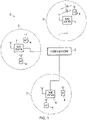
- Figure 1 provides a schematic diagram illustrating some basic functionality of a mobile telecommunications network / system 6 operating generally in accordance with LTE principles, but which may also support other radio access technologies, and which may be adapted to implement embodiments of the disclosure as described herein.
- Various elements of Figure 1 and certain aspects of their respective modes of operation are well-known and defined in the relevant standards administered by the 3GPP (RTM) body, and also described in many books on the subject, for example, Holma H. and Toskala A [5].
- the network 6 includes a plurality of base stations 1 connected to a core network 2. Each base station provides a coverage area 3 (i.e. a cell) within which data can be communicated to and from communications devices 4. Data is transmitted from base stations 1 to communications devices 4 within their respective coverage areas 3 via a radio downlink. Data is transmitted from communications devices 4 to the base stations 1 via a radio uplink.
- the core network 2 routes data to and from the communications devices 4 via the respective base stations 1 and provides functions such as authentication, mobility management, charging and so on. Terminal devices may also be referred to as mobile stations, user equipment (UE), user terminal, mobile radio, communications device, and so forth.
- Base stations which are an example of network infrastructure equipment, may also be referred to as transceiver stations, nodeBs, e-nodeBs, eNB, g-nodeBs, gNB and so forth.
- nodeBs nodeBs
- e-nodeBs nodeBs
- eNB nodeB
- g-nodeBs gNodeBs
- FIG. 2 An example configuration of a wireless communications network which uses some of the terminology proposed for NR and 5G is shown in Figure 2 .
- a 3GPP Study Item (SI) on New Radio Access Technology (NR) has been defined [2].
- a plurality of transmission and reception points (TRPs) 10 are connected to distributed control units (DUs) 41, 42 by a connection interface represented as a line 16.
- DUs distributed control units
- Each of the TRPs 10 is arranged to transmit and receive signals via a wireless access interface within a radio frequency bandwidth available to the wireless communications network.
- each of the TRPs 10 forms a cell of the wireless communications network as represented by a dashed line 12.
- Each of the distributed control units 41, 42 are connected to a central unit (CU) 40 via an interface.
- the central unit 40 is then connected to the a core network 20 which may contain all other functions required to transmit data for communicating to and from the wireless communications devices and the core network 20 may be connected to other networks 30.
- the elements of the wireless access network shown in Figure 2 may operate in a similar way to corresponding elements of an LTE network as described with regard to the example of Figure 1 .
- operational aspects of the telecommunications network represented in Figure 2 and of other networks discussed herein in accordance with embodiments of the disclosure, which are not specifically described (for example in relation to specific communication protocols and physical channels for communicating between different elements) may be implemented in accordance with any known techniques, for example according to currently used approaches for implementing such operational aspects of wireless telecommunications systems, e.g. in accordance with the relevant standards.
- the TRPs 10 of Figure 2 may in part have a corresponding functionality to a base station or eNodeB of an LTE network.
- the communications devices 14 may have a functionality corresponding to UE devices known for operation with an LTE network.
- operational aspects of a new RAT network may be different to those known from LTE or other known mobile telecommunications standards.
- each of the core network component, base stations and communications devices of a new RAT network will be functionally similar to, respectively, the core network component, base stations and communications devices of an LTE wireless communications network.
- the core network 30 of the new RAT telecommunications system represented in Figure 2 may be broadly considered to correspond with the core network 2 represented in Figure 1
- the respective controlling nodes 40 and their associated distributed units / TRPs 10 may be broadly considered to provide functionality corresponding to base stations of Figure 1 .
- the term network infrastructure equipment / access node may be used to encompass these elements and more conventional base station type elements of wireless telecommunications systems.
- the responsibility for scheduling transmissions which are scheduled on the radio interface between the respective distributed units and the communications devices may lie with the controlling node / centralised unit and / or the distributed units / TRPs.
- a communications device 14 is represented in Figure 2 within the coverage area of the first communication cell 12. This communications device 14 may thus exchange signalling with the first controlling node 40 in the first communication cell 212 via one of the distributed units 10 associated with the first communication cell 12.
- Figure 2 represents merely one example of a proposed architecture for a new RAT telecommunications system in which approaches in accordance with the principles described herein may be adopted, and the functionality disclosed herein may also be applied in respect of wireless telecommunications systems having different architectures.
- the network infrastructure equipment / access node may comprise a base station, such as an LTE-type base station 11 as shown in Figure 1 which is adapted to provide functionality in accordance with the principles described herein, and in other examples the network infrastructure equipment may comprise a control unit / controlling node 40 and / or a TRP 10 of the kind shown in Figure 2 which is adapted to provide functionality in accordance with the principles described herein.
- a base station such as an LTE-type base station 11 as shown in Figure 1 which is adapted to provide functionality in accordance with the principles described herein
- the network infrastructure equipment may comprise a control unit / controlling node 40 and / or a TRP 10 of the kind shown in Figure 2 which is adapted to provide functionality in accordance with the principles described herein.
- RRC Radio Resource Control
- RRC_IDLE RRC idle mode
- RRC connected mode RRC CONNECTED
- EMM-REGISTERED ECM-REGISTERED
- ECM-IDLE active communication
- RRC idle mode a UE is not connected to a radio network access node in the sense of not being able to communicate user plane data using the radio network access node.
- the UE may still receive some communications from base stations, for example reference signalling for cell reselection purposes and other broadcast signalling.
- the RRC connection setup procedure of going from RRC idle mode to RRC connected mode may be referred to as connecting to a cell / base station.
- the core network For a UE in RRC idle mode the core network is aware that the UE is present within the network, but the radio access network (RAN) part (comprising radio network infrastructure equipment such as the base stations 1 of Figure 1 and / or the combined TRPs / CUs 10, 40, 42 of Figure 2 ) is not.
- the core network is aware of the location of idle mode UEs at a paging tracking area level but not at the level of individual transceiver entities.
- the core network will generally assume a UE is located within the tracking area(s) associated with a transceiver entity most recently used for communicating with the UE, unless the UE has since provided a specific tracking area update (TAU) to the network.
- TAU tracking area update
- idle mode UEs are typically required to send a TAU when they detect they have entered a different tracking area to allow the core network to keep track of their location.
- the core network tracks UEs at a tracking area level, it is generally not possible for the network infrastructure to know which specific transceiver entities (radio network node) to use when seeking to initiate contact with a UE in idle mode. Consequently, and as is well known, when a core network is required to connect to an idle mode UE a paging procedure is used.
- Embodiments of the present technique can provide an arrangement in which a wireless communications device, such as for example a UE, operates as a base station or TRP in accordance with a 5G architecture in which it does not have a physical connection to other infrastructure equipment (DU or CU) forming part of a radio access network to a core network of the wireless communications network, such as a DU 10.
- a wireless communications device such as for example a UE
- DU or CU infrastructure equipment
- another TRP 10 operates to provide a wireless communications channel for both forward traffic from the core network to the communications device acting as a TRP and a backward channel from the communications device acting as a TRP for the core network.
- the communications device acting as a TRP to form a cell of the wireless communications network which connects to an infrastructure equipment of the wireless communications network (DU) via another TRP will be referred to as a remote node, whereas the TRP providing the wireless connection to the wireless communications network may be referred to as a relay node.
- Example embodiments provide an arrangement in which the remote node is a network node which acts like a UE when in Idle mode.
- the wireless network interface/connection is provide by wireless communications forward channel and backward channel which may use the same wireless access interface as the UEs (in-band) or may use a different wireless communications interface on different radio frequencies (out of band).
- the forward channel and the backward channel therefore perform a wireless network interface referred to colloquially as a 'backhaul' connection. If both relay node and the remote node are operating on the same frequency then one node can either transmit or receive but may not perform both actions at the same time.
- a TRP10 as shown in Figure 2 comprises, as a simplified representation, a wireless transmitter 30, a wireless receiver 32 and a controller or controlling processor 34 which may operate to control the transmitter 30 and the wireless receiver 32 to transmit and receive radio signals to one or more UEs 14 within a cell 12 formed by the TRP 10.
- an example UE 14 is shown to include a corresponding transmitter 40, a receiver 42 and a controller 44 which is configured to control the transmitter and receiver to transmit signals representing uplink data to the wireless communications network via the wireless access interface formed by the TRP 10 and to receive downlink data as signals transmitted by the transmitter 30 and receiver 42 in accordance with the conventional operation.
- the transmitters 30, 40, the receivers 32, 42 may include radio frequency filters and amplifiers as well as signal processing components and devices in order to transmit and receive radio signals in accordance for example with the 5G standard.
- the TRP 10 also includes a network interface 50 which connects to the DU 42 via a physical interface 16.
- the network interface therefore provides a communication of data and signalling traffic from the TRP 10 via the DU 42 and the CU 40 to the core network 20.
- the interface between the DU 42 and the CU 40 is known as the F1 interface which can be a physical or a logical interface.
- the F1 interface between CU and DU is specified in 3GPP TS 38.470, 38.473.
- the connection from the TRP to the DU is via fibre optic.
- the connection to the core network can be generally referred to as a backhaul including the interface 16 from the network interface 50, the TRP10 to the DU 42.
- the interface or connection of the network between a communications device acting as a TRP to form a cell is formed by a wireless connection to another TRP 10 acting as a relay node.
- a wireless connection to another TRP 10 acting as a relay node is shown in Figure 4 .
- a first TRP 10 is connected to a DU 42 by a physical interface 16 using a network interface 50.
- the first TRP 10 therefore forms a first cell A 402 in a conventional manner by transmitting and receiving signals via a wireless access interface provided by the radio network part of a wireless communications network.
- two other communications devices are configured to act as TRPs 110, 112 to form to other cells B and C 404, 406.
- the first TRP 10 is therefore acting as a relay node to the second and third TRPs 110, 112 which act as remote nodes.
- the second TRP 110 is a wireless communications device shown to comprise a transmitter 130, a receiver 132 and a controller 134.
- the second TRP 112 is a wireless communications device comprising a transmitter 130, a receiver 132, and a controller 134.
- the second TRP 110 acts as a remote node to form the cell 404 B and the third TRP 112 acts as a remote node to form the cell 406 C.
- the UEs 14 operating within these cells 404, 406 transmit and receive radio signals via the wireless access interface provided by the radio network part of the wireless communication in the same way as a UE 14 would transmit and receive radio signals via the wireless access interface provided by the TRP10 from cell 402 A.
- the wireless communications devices forming the TRPs 110, 112 do not include a network interface 50 but form a connection to the DU 42 of the wireless communications network via the first TRP 10 of the cell 402 A by configuring a wireless communications forward channel and a wireless communications reverse channel to and from the first TRP 10 to form a backhaul connection interface 160.
- the backhaul connection 160 is therefore a wireless network interface to the first TRP 10 and the physical backhaul interface 16 to the DU42.
- the second and third TRPs 110, 112 formed by the wireless communications devices are remote nodes of the wireless communications network and form part of the radio access network.
- the first TRP 10 therefore acts as a donor or a relay node, sometimes referred to as a donor eNode-b in 4G or other 3GPP standards.
- Example embodiments of the present technique can effect two aspects in which wireless communications devices acting as remote nodes forming TRPs 110, 112 are configured differently to a conventional wireless communications device or UE 14.
- the communications device acting as a remote node or TRP 110 may receive information from the relay node (TRP 10) via both the backhaul wireless interface connection 160 and also a conventional wireless access interface which is transmitted to all UEs 14 for example within the same cell 404.
- the wireless communications device acting as a remote node (TRP 110) therefore is configured differently to a conventional UE 14 in respect of how the TRP 110 either uses the information or selects the information for transmission to UEs 40 served by a cell 404 formed by that remote node (TRP 110).
- a second aspect is how the TRP 110 selects one of the other TRPs 10 to act as a relay node or relay TRP 10. This aspect is explained with reference to Figure 5 .
- TRPs 510 are shown to be connected to a DU 42 which is then connected to the CU 40 as with a conventional arrangement as shown in Figures 2 and 3 .
- the UEs 14 therefore transmit and receive radio signals representing data on the uplink and the downlink as for conventional operation via the conventional TRPs 510.
- three other TRPs 520, 522, 524 are formed by wireless communications devices acting as remote nodes forming the TRPs 520, 522, 524 and therefore have established wireless network interface or backhaul 160, 162, 164 via two of the TRPs 510 to the DU 42 as explained with reference to Figure 4 .
- a remote node TRP 520 could have established the wireless network interface via any one of the other TRPs 510 having a physical network interface 16 to the core network.
- the first remote node TRP 520 as with the second remote node TRP 522 performs a selection process to identify which of the plurality of other TRPs 510 is selected in order to establish wireless forward and reverse channels of the network interface to establish the backhaul connections 160, 162.
- each of the TRPs 510 transmits an indication as to whether or not it can act as a relay node for another TRP 520, 522. If the TRP does not transmit an indication that it can act as a relay node then the wireless communications device acting as a remote node TRP 520, 522 ignores any of the plurality of TRPs 510 which cannot act as a relay node when selecting the TRP 510 to be its relay node.
- each of the other TRP's 510 may transmit an access class or an indication of access classes which are barred (access class barring). If an access class indicates that a TRP cannot act as a relay node for wireless communications device acting as a remote node TRP 520, 522 then this TRP is ignored by the communications device.
- a third wireless communications devices acting as a remote node TRP 524 is provided with a wireless network interface or backhaul 164 via the second communications device acting as a remote node TRP 522 which itself receives a wireless network interface via the backhaul interface 162 to a TRP 510.
- the TRPs 510 may transmit an indication as to whether or not they allow a connection to a wireless communications device which itself is acting as a relay node to another wireless communications device acting as a TRP. This is a so-called "hop", that is core network signaling and user data is transmitted and received via more than one TRP acting as a relay node.
- the third TRP 524 may receive via the secondary wireless communications device 522 from the primary TRP 510 an indication that it can act as a relay node through another relay node and an indication of a number of hops which can be supported. Accordingly, the third remote node TRP 524 only selects TRPs which can support a multi-hop interface.
- remote nodes 520, 522, 524 may be in IDLE mode once they power on and will perform a synchronisation procedure and read any necessary system information transmitted from the relay node TRP 510.
- the relay node TRP 510 therefore are configured to support relaying operations and indicate support of relaying system information.
- the remote nodes read a mast information block (MIB) as well as system information blocks, SIB1 and SIB2.
- MIB mast information block
- SIB1 and SIB2 system information blocks
- these SIBs may have a similar structure to LTE MIB, SIB1, SIB2.
- the remote nodes read the system information in order to check if the candidate cell supports:
- a remote node may not read SIBs related to cell reselection and other service related SIBs, which may not have any relevance to a communications device acting as a remote node. Such information may be provided in dedicated signalling as a remote node may have exceptional priority. A remote node will then move to a connected mode in order to receive the dedicated signalling. However, a remote node can behave like a UE when in IDLE mode. This implies that the remote node will support some services such as on-demand SI methods when in Idle mode.
- a UE forming a remote node selects another TRP to act as a relay node, when the UE is an Idle mode in which it does not have an active connection to the wireless communications network.
- a communications device which acts as a remote node TRP can behave differently in respect of the detection of information which may be transmitted different from the core network for different applications such as signalling or broadcast information for UEs within a cell formed by the wireless communications device.
- Such an example is shown in Figure 6 .
- one of the TRPs 510 shown in Figure 5 is shown with the DU 40 connected via a physical interface 16 to form the backhaul to the core network.
- a wireless network interface 160 formed from a wireless forward and a reverse channel provided by the TRP 510 to one of the wireless communications devices acting as a TRP 520.
- the first TRP 510 therefore forms a first cell 540 and the second TRP 520 forms a second cell 542.
- the TRP 510 receives system information, which is locally configured via an OAM function or received from the core network from the physical backhaul interface 16 via the DU 40.
- the system information therefore must be transmitted periodically to UEs 14 operating within the first cell 540.
- this system information is represented by a box 600.
- the TRP 510 transmits this system information 600 to all UEs 14 within this first cell 540 but this is also received by the wireless communications device acting as a remote node TRP 520 as shown by arrows 602, 604.
- the system information 600 will also be received via the wireless network interface 160 at the wireless communications device acting as the remote node TRP 520 for transmission to UEs 14 within the second cell 542. Accordingly, the second TRP 520 receives another version of the system information 610 via the wireless network interface from the forward channel from the relay node TRP 510. According to this example embodiment therefore, the wireless communications device acting as a TRP 520 ignores the version of the system information 600 it received from the conventional wireless access interface broadcast within the first cell 540 and only acts upon the second version of the system information 610 it received via the wireless network interface 160.
- broadcast information may be received via the conventional wireless access interface from the relay node TRP 510 but also received via the wireless network interface 160 from the relay node TRP 510.
- the wireless communications device acting as a remote node TRP 520 therefore selects the version of the broadcast information received via the wireless network interface 160 for transmission to UEs 14 within the second cell 542.
- this broadcast information may be public warning system information (PWS) or early warning or Earthquake and Tsunami Warning System information (ETWS).
- PWS public warning system information
- ETWS early warning or Earthquake and Tsunami Warning System information
- This broadcast information may also include MBMS data.
- the PWS, ETWS, MBMS and other service related information may not be broadcasted by the relay node TRP 510 at a time when the remote node powers on or when the remote node was in the IDLE mode, because the warning and MBMS service or other services may be transmitted later.
- the DU 42 may start broadcasting the warning information as soon as it received the warning information from the CU 40.
- the remote node TRP 520 will receive the warning information from CU to DUs at remote node 520 which can also be received from both backhaul link.
- the remote node TRP 520 ignores the system information received over the air (SIBs) and takes the information received via theF1 interface or information received via any similar interface into account.
- SIBs system information received over the air
- the rationale behind this approach is that some PWS warning messages like ETWS primary notification have strict delay requirements i.e. end to end delay of 4 seconds.
- the relay node may prioritize backhaul transmissions over its own SIBs transmission so that the delay budget or latency requirements can be met. If relay node does not prioritize or provide exceptional treatment while scheduling backhaul for remote nodes then the end to end latency target may not be met.
- Embodiments can also provide an advantage because the integrity of PWS or other services related information may be compromised over the air (SIBs) as SIBs are not encrypted or SIBs may be broadcasted by a rogue base station.
- SIBs services related information
- F1 interface between CU and DU may have to fulfill the security requirements and AS level of security will always be active between a relay node and remote node over the wireless network interface, once the remote node is in RRC_Connected mode.
- BWP bandwidth part
- a receiver receiving system information from a relay node will never trigger an on-demand SI request in RRC Connected mode.
- F1 interface specifications must ensure that the same information as on-demand SI request in connected mode is available. This is due to factors like latency and security as mentioned above.
- a remote node may receive system information of one or more cells in parallel (multiple tx/rx) and the F1 interface information/configuration also relayed from one or more than one cells. In this case, selection between different links of F1 interface information/configuration should be for the remote node to decide when in connected mode.
- the example embodiments described above provide an arrangement in which a wireless communications device (UE) acts as a TRP to form a remote node of a wireless communications network by selecting another TRP, when in an idle mode, to provide a wireless network interface (backhaul) to core network components of the network.
- UE wireless communications device
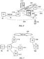
- Figure 7 provides an alternative architecture based on the example embodiment of Figure 6 .
- one of the TRPs 710 from a plurality of TRPs 510, 710 has been selected by a communications device acting as a relay node 720.
- the remote node includes a DU 740 and so in combination the TRP 720 and the DU 740 form a cell 750.
- the wireless communications device may in some example perform the functionality of the TRP 720 and is connected separately to the DU 740 or the wireless communications device forms the functionality of the TRP 720 and the DU 740.
- the wireless network interface through the TRP 710 acting as a relay node provides an interface through to the CU 40 via the other DU 42 and therefore provides a forward and a reverse channel to and from the CU 40 as a logical F1 interface.
- Embodiments of the present technique have been described with reference with a 5G network architecture. However, the embodiments of the present technique find application equally with other network architectures and systems standards and is not limited to 5G. Furthermore, network architecture may change from the embodiments presented above.
- infrastructure equipment and/or communications devices as herein defined may be further defined in accordance with the various arrangements and embodiments discussed in the preceding paragraphs. It would be further appreciated by those skilled in the art that such infrastructure equipment and communications devices as herein defined and described may form part of communications systems other than those defined by the present invention.
- Described embodiments may be implemented in any suitable form including hardware, software, firmware or any combination of these. Described embodiments may optionally be implemented at least partly as computer software running on one or more data processors and/or digital signal processors.
- the elements and components of any embodiment may be physically, functionally and logically implemented in any suitable way. Indeed the functionality may be implemented in a single unit, in a plurality of units or as part of other functional units. As such, the disclosed embodiments may be implemented in a single unit or may be physically and functionally distributed between different units, circuitry and/or processors.
Landscapes
- Engineering & Computer Science (AREA)
- Computer Networks & Wireless Communication (AREA)
- Signal Processing (AREA)
- Computer Security & Cryptography (AREA)
- Mobile Radio Communication Systems (AREA)
Claims (12)
- Dispositif de communication sans fil (520) destiné à agir comme un nœud distant d'un réseau de communication sans fil, le dispositif de communication sans fil (520) comprenant :des circuits d'émetteur (130) pour émettre des signaux radio par l'intermédiaire de l'interface d'accès sans fil d'une partie de réseau d'accès radio du réseau de communication sans fil,des circuits de récepteur (132) pour recevoir des signaux radio transmis par l'intermédiaire de l'interface d'accès sans fil de la partie de réseau d'accès radio, etdes circuits de contrôleur (134) configurés :pour sélectionner, lorsque le dispositif de communication sans fil (520) est dans un mode inactif dans lequel il n'a pas établi de connexion au réseau de communication sans fil, un équipement d'infrastructure (510) faisant partie du réseau d'accès radio du réseau de communication sans fil pour fournir une interface de réseau sans fil formée par un canal aller d'interface de réseau et un canal retour d'interface de réseau avec une partie de réseau central du réseau de communication sans fil par l'intermédiaire de l'équipement d'infrastructure sélectionné (510), qui agit comme un nœud de relais,pour commander les circuits d'émetteur (130) afin de transmettre des signaux radio par l'intermédiaire du canal retour d'interface de réseau à l'équipement d'infrastructure sélectionné (510) agissant en tant que nœud de relais, les signaux radio représentant des données de liaison montante reçues d'un ou plusieurs dispositifs de communication (14) pour une transmission au réseau central, lorsque le dispositif de communication sans fil (520) fonctionne en tant que nœud distant,pour commander les circuits de récepteur (132) afin de recevoir des signaux radio par l'intermédiaire du canal aller d'interface de réseau à partir de l'équipement d'infrastructure sélectionné (510) agissant en tant que nœud de relais, les signaux radio représentant des données de liaison descendante pour une transmission à un ou plusieurs dispositifs de communication (14) reçus de la partie de réseau central du réseau de communication sans fil, lorsque le dispositif de communication sans fil (14) fonctionne en tant que nœud distant,pour commander les circuits de récepteur (132) afin de recevoir une première version des informations système (600) transmises par l'équipement d'infrastructure sélectionné (510) par l'intermédiaire de l'interface d'accès sans fil et de recevoir une seconde version des informations système (610) transmises par l'équipement d'infrastructure sélectionné (510) par l'intermédiaire du canal aller de l'interface de réseau lorsque le dispositif de communication sans fil (520) est dans un mode connecté dans lequel il a établi une connexion au réseau de communication sans fil, etpour configurer les circuits d'émetteur (130) ou les circuits de récepteur (132) pour adapter l'interface d'accès sans fil conformément à la seconde version des informations système (610) et pour ignorer la première version des informations système (600).
- Dispositif de communication sans fil (520) tel que revendiqué dans la revendication 1, dans lequel les circuits de récepteur (132) sont configurés pour recevoir une première version d'informations de diffusion transmises par l'équipement d'infrastructure sélectionné par l'intermédiaire de l'interface d'accès sans fil et pour recevoir une seconde version des informations de diffusion par l'intermédiaire du canal aller de l'interface de réseau depuis l'équipement d'infrastructure sélectionné, et pour configurer les circuits d'émetteur (130) pour transmettre des signaux basés sur la seconde version des informations de diffusion à un ou plusieurs dispositifs de communication.
- Dispositif de communication sans fil (520) tel que revendiqué dans la revendication 2, dans lequel les informations de diffusion sont des informations de diffusion d'urgence ou d'avertissement ou des informations de diffusion liées à un service.
- Dispositif de communication sans fil (520) tel que revendiqué dans la revendication 1, dans lequel, en mode inactif, les circuits de récepteur (132) sont configurés pour recevoir des informations système à la demande en réponse à la transmission d'une demande d'informations système à la demande à l'équipement d'infrastructure sélectionné fournissant l'interface de réseau sans fil au réseau central.
- Dispositif de communication sans fil (520) tel que revendiqué dans la revendication 1, dans lequel les circuits de contrôleur (134) sont configurés, lorsqu'ils sont en mode inactif, pour sélectionner l'équipement d'infrastructure à partir d'une pluralité d'équipements d'infrastructure pour fournir l'interface de réseau sans fil en réponse à la réception, en utilisant les circuits de récepteur (132), à partir de l'équipement d'infrastructure sélectionné, d'une indication que l'équipement d'infrastructure sélectionné peut former l'interface de réseau sans fil pour le dispositif de communication sans fil ou, si l'indication n'est pas reçue, les circuits de contrôleur (134) sont configurés pour sélectionner un équipement différent de la pluralité d'équipements d'infrastructure pour former l'interface de réseau sans fil.
- Dispositif de communication sans fil (520) tel que revendiqué dans la revendication 5, dans lequel les circuits de contrôleur (134) sont configurés pour sélectionner l'équipement d'infrastructure même si les circuits de récepteur (132) reçoivent une indication dans les informations système que l'équipement d'infrastructure sélectionné est réservé pour une utilisation par un opérateur.
- Dispositif de communication sans fil (520) tel que revendiqué dans la revendication 1, dans lequel les circuits de contrôleur (134) sont configurés, lorsqu'ils sont en mode inactif, pour sélectionner l'équipement d'infrastructure à partir d'une pluralité d'équipements d'infrastructure pour fournir l'interface de réseau sans fil en réponse à la réception, en utilisant les circuits de récepteur (132), à partir d'une ou plusieurs informations système de la pluralité d'équipements d'infrastructure qui comprennent une indication du fait que l'équipement d'infrastructure est, ou non, une cellule interdite, les circuits de contrôleur (134) étant configurés pour sélectionner l'équipement d'infrastructure sur la base d'une indication que l'équipement d'infrastructure sélectionné n'est pas un équipement pour lequel il est interdit de former l'interface de réseau sans fil pour agir comme un nœud de relais pour le dispositif de communication sans fil (520) agissant comme un nœud distant.
- Dispositif de communication sans fil (520) tel que revendiqué dans la revendication 1, dans lequel les circuits de contrôleur (134) sont configurés, lorsqu'ils sont en mode inactif, pour sélectionner l'équipement d'infrastructure parmi une pluralité d'équipements d'infrastructure pour fournir l'interface de réseau sans fil en réponse à la réception, en utilisant les circuits de récepteur (132), d'un ou plusieurs des équipements d'infrastructure, d'une indication d'interdiction de classe d'accès indiquant si l'équipement d'infrastructure ne peut pas être utilisé pour former l'interface de réseau sans fil pour le dispositif de communication sans fil, les circuits de contrôleur (134) étant configurés pour sélectionner l'équipement d'infrastructure sur la base de l'indication d'interdiction de classe d'accès, l'équipement d'infrastructure sélectionné étant capable de former l'interface de réseau sans fil et d'agir comme un nœud de relais pour le dispositif de communication sans fil (520) agissant comme un nœud distant.
- Dispositif de communication sans fil (520) tel que revendiqué dans la revendication 1, dans lequel les circuits de contrôleur (134) sont configurés, lorsqu'ils sont en mode inactif, pour sélectionner l'équipement d'infrastructure parmi une pluralité d'équipements d'infrastructure pour fournir l'interface de réseau sans fil en réponse à la réception, en utilisant les circuits de récepteur (132), à partir d'un ou plusieurs de la pluralité d'équipements d'infrastructure par l'intermédiaire d'un ou plusieurs équipements d'infrastructure secondaires, d'une indication que l'équipement d'infrastructure peut agir comme un nœud de relais par l'intermédiaire d'un autre nœud de relais et d'une indication d'un nombre maximum de sauts qui peuvent être supportés, et pour sélectionner l'équipement d'infrastructure sur la base de l'indication que l'équipement d'infrastructure peut agir comme un nœud de relais par l'intermédiaire d'un autre nœud de relais et de l'indication d'un nombre maximum de sauts qui peuvent être supportés.
- Dispositif de communication sans fil (520) tel que revendiqué dans la revendication 1, dans lequel les circuits de contrôleur (134) sont configurés, lorsqu'ils sont en mode inactif, pour sélectionner l'équipement d'infrastructure parmi une pluralité d'équipements d'infrastructure pour fournir l'interface de réseau sans fil en réponse à la réception, en utilisant les circuits de récepteur (132), à partir d'un ou plusieurs des équipements d'infrastructure, d'une indication que l'équipement d'infrastructure est configuré avec une partie de bande passante réservée pour fournir une ressource dédiée pour former l'interface de réseau sans fil à partir de l'équipement d'infrastructure agissant comme un nœud de relais vers le dispositif de communication sans fil agissant comme un nœud distant, les circuits de contrôleur (134) étant configurés pour sélectionner l'équipement d'infrastructure si l'indication indique qu'il supporte une partie de bande passante réservée.
- Dispositif de communication sans fil (520) tel que revendiqué dans la revendication 1, dans lequel les circuits de contrôleur (134) sont configurés, lorsqu'ils sont dans un mode connecté, pour sélectionner l'équipement d'infrastructure parmi une pluralité d'équipements d'infrastructure pour fournir l'interface de réseau sans fil en réponse à la réception, en utilisant les circuits de récepteur (132), depuis un ou plusieurs des équipements d'infrastructure, d'une indication que l'équipement d'infrastructure est configuré avec une partie de bande passante réservée pour fournir une ressource dédiée pour former l'interface de réseau sans fil depuis l'équipement d'infrastructure agissant comme un nœud de relais vers le dispositif de communication sans fil agissant comme un nœud distant, les circuits de contrôleur (134) étant configurés pour sélectionner l'équipement d'infrastructure si l'indication indique qu'il supporte une partie de bande passante réservée dans laquelle transmettre des informations de système séparément des informations de système transmises aux dispositifs de communication desservis par l'équipement d'infrastructure sélectionné.
- Procédé d'exploitation d'un dispositif de communication sans fil (520) pour agir en tant que nœud distant d'un réseau d'accès sans fil, le procédé comprenant les étapes suivantes :sélectionner, par des circuits de contrôleur (134) du dispositif de communication sans fil (520), lorsque le dispositif de communication sans fil (520) est dans un mode inactif dans lequel il n'a pas établi de connexion au réseau de communication sans fil, un équipement d'infrastructure faisant partie du réseau d'accès radio du réseau de communication sans fil pour fournir une interface de réseau sans fil formée par un canal aller d'interface de réseau et un canal retour d'interface de réseau avec une partie de réseau central du réseau de communication sans fil par l'intermédiaire de l'équipement d'infrastructure sélectionné, commander, par les circuits de contrôleur (134) du dispositif de communication sans fil (520), des circuits d'émetteur (130) du dispositif de communication sans fil (520) pour transmettre des signaux radio par l'intermédiaire du canal retour d'interface de réseau à l'équipement d'infrastructure sélectionné, les signaux radio représentant des données de liaison montante reçues d'un ou plusieurs dispositifs de communication pour une transmission au réseau central lorsque le dispositif de communication sans fil fonctionne en tant que nœud distant,commander, par les circuits de contrôleur (134) du dispositif de communication sans fil (520), des circuits de récepteur (132) du dispositif de communication sans fil (520) pour recevoir des signaux radio par l'intermédiaire du canal aller d'interface de réseau à partir de l'équipement d'infrastructure sélectionné, les signaux radio représentant des données de liaison descendante pour une transmission vers un ou plusieurs dispositifs de communication reçus de la partie de réseau central du réseau de communication sans fil lorsque le dispositif de communication sans fil (520) fonctionne en tant que nœud distant,commander, par les circuits de contrôleur (134) du dispositif de communication sans fil (520), les circuits de récepteur (132) du dispositif de communication sans fil (520) pour recevoir une première version d'informations système (600) transmises depuis l'équipement d'infrastructure sélectionné par l'intermédiaire de l'interface d'accès sans fil et pour recevoir une seconde version des informations système (610) transmises depuis l'équipement d'infrastructure sélectionné (510) par l'intermédiaire du canal aller d'interface de réseau lorsque le dispositif de communication sans fil (520) est dans un mode connecté dans lequel il a établi une connexion au réseau de communication sans fil, etconfigurer, par les circuits de contrôleur (134) du dispositif de communication sans fil (520), les circuits d'émetteur (130) du dispositif de communication sans fil (520) ou les circuits de récepteur (132) du dispositif de communication sans fil (520) pour adapter l'interface d'accès sans fil conformément à la seconde version des informations système (610) et pour ignorer la première version des informations système (600).
Priority Applications (1)
| Application Number | Priority Date | Filing Date | Title |
|---|---|---|---|
| EP22206629.2A EP4161160A1 (fr) | 2018-01-11 | 2019-01-03 | Dispositif et procédé de communication sans fil |
Applications Claiming Priority (2)
| Application Number | Priority Date | Filing Date | Title |
|---|---|---|---|
| EP18151305 | 2018-01-11 | ||
| PCT/EP2019/050111 WO2019137848A1 (fr) | 2018-01-11 | 2019-01-03 | Dispositif et procédé de communication sans fil |
Related Child Applications (2)
| Application Number | Title | Priority Date | Filing Date |
|---|---|---|---|
| EP22206629.2A Division-Into EP4161160A1 (fr) | 2018-01-11 | 2019-01-03 | Dispositif et procédé de communication sans fil |
| EP22206629.2A Division EP4161160A1 (fr) | 2018-01-11 | 2019-01-03 | Dispositif et procédé de communication sans fil |
Publications (2)
| Publication Number | Publication Date |
|---|---|
| EP3738352A1 EP3738352A1 (fr) | 2020-11-18 |
| EP3738352B1 true EP3738352B1 (fr) | 2022-12-28 |
Family
ID=61022115
Family Applications (2)
| Application Number | Title | Priority Date | Filing Date |
|---|---|---|---|
| EP22206629.2A Pending EP4161160A1 (fr) | 2018-01-11 | 2019-01-03 | Dispositif et procédé de communication sans fil |
| EP19700026.8A Active EP3738352B1 (fr) | 2018-01-11 | 2019-01-03 | Dispositif et procédé de communication sans fil |
Family Applications Before (1)
| Application Number | Title | Priority Date | Filing Date |
|---|---|---|---|
| EP22206629.2A Pending EP4161160A1 (fr) | 2018-01-11 | 2019-01-03 | Dispositif et procédé de communication sans fil |
Country Status (3)
| Country | Link |
|---|---|
| US (2) | US11277784B2 (fr) |
| EP (2) | EP4161160A1 (fr) |
| WO (1) | WO2019137848A1 (fr) |
Families Citing this family (3)
| Publication number | Priority date | Publication date | Assignee | Title |
|---|---|---|---|---|
| US11277784B2 (en) * | 2018-01-11 | 2022-03-15 | Sony Corporation | Wireless communications device and method |
| US20210036764A1 (en) * | 2019-08-01 | 2021-02-04 | Qualcomm Incorporated | Control method for smart repeaters |
| US11611421B2 (en) * | 2019-08-05 | 2023-03-21 | Qualcomm Incorporated | Techniques for in-band repeater control |
Family Cites Families (30)
| Publication number | Priority date | Publication date | Assignee | Title |
|---|---|---|---|---|
| US20040063451A1 (en) * | 2002-09-27 | 2004-04-01 | Bonta Jeffrey D. | Relaying information within an ad-hoc cellular network |
| WO2009014764A1 (fr) * | 2007-07-25 | 2009-01-29 | Teenay Wireless, Inc. | Système de réseau de liaisons multiniveau ayant des capacités de différenciation de trafic et de traitement avancées et procédés pour celui-ci |
| WO2009113976A1 (fr) * | 2008-03-11 | 2009-09-17 | Thomson Licensing | Association, routage et attribution de débit conjoints dans des réseaux maillés à sauts multiples sans fil |
| CA2725065A1 (fr) * | 2008-05-20 | 2009-11-26 | Live Meters, Inc. | Systeme de surveillance et de commande a distance comprenant la technologie mesh et de synchronisation temporelle |
| KR20140068059A (ko) * | 2011-09-12 | 2014-06-05 | 에스씨에이 아이피엘에이 홀딩스 인크. | 로컬 데이터 저장소로부터의 콘텐츠 데이터를 통신 단말기에 전달하기 위한 방법 및 장치 |
| US10129928B2 (en) * | 2012-12-14 | 2018-11-13 | Huawei Technologies Co., Ltd. | System and method for UE fountain relay based network |
| US9572171B2 (en) * | 2013-10-31 | 2017-02-14 | Intel IP Corporation | Systems, methods, and devices for efficient device-to-device channel contention |
| RU2703512C2 (ru) * | 2014-11-07 | 2019-10-18 | Интердиджитал Пэйтент Холдингз, Инк. | Оптимизации для ретрансляционной связи |
| US10506491B2 (en) * | 2015-04-06 | 2019-12-10 | Lg Electronics Inc. | Method and apparatus for transmitting relay request indication in wireless communication system |
| JP6985152B2 (ja) * | 2015-04-08 | 2021-12-22 | インターデイジタル パテント ホールディングス インコーポレイテッド | デバイスツーデバイス(d2d)通信のモバイル中継器の実現 |
| JPWO2016163541A1 (ja) * | 2015-04-09 | 2018-02-01 | 株式会社Nttドコモ | ユーザ端末及び無線通信方法 |
| JP6337198B2 (ja) * | 2015-04-10 | 2018-06-06 | 京セラ株式会社 | 無線端末、プロセッサ及び制御方法 |
| WO2016182597A1 (fr) * | 2015-05-14 | 2016-11-17 | Intel IP Corporation | Initiation et configuration de relais d'un ue à un réseau |
| US10212651B2 (en) * | 2015-05-14 | 2019-02-19 | Qualcomm Incorporated | Systems, methods, and devices for link quality based relay selection |
| US10694579B2 (en) * | 2015-05-22 | 2020-06-23 | Sony Corporation | Communications terminals, infrastructure equipment and methods, for UE:s acting as relays |
| WO2016206998A1 (fr) * | 2015-06-24 | 2016-12-29 | Sony Corporation | Resélection de nœud déterminée par le réseau sur des signaux de balise d'ue reçus |
| EP3354081B1 (fr) * | 2015-09-25 | 2019-11-06 | Sony Corporation | Système de télécommunications sans fil |
| US9867114B2 (en) * | 2016-02-04 | 2018-01-09 | Sprint Communications Company L.P. | Wireless relay backhaul selection in a data communication network |
| US10630410B2 (en) | 2016-05-13 | 2020-04-21 | Telefonaktiebolaget Lm Ericsson (Publ) | Network architecture, methods, and devices for a wireless communications network |
| US10314057B1 (en) * | 2016-10-18 | 2019-06-04 | Sprint Spectrum L.P. | Managing allocation of resources to a relay-UE based on a determination that the relay-UE is positioned within an indoor environment |
| WO2018082869A1 (fr) * | 2016-11-03 | 2018-05-11 | Sony Corporation | Appareils et procédés de télécommunications sans fil |
| CN110169138B (zh) * | 2017-01-06 | 2022-04-29 | 瑞典爱立信有限公司 | 系统信息中的寻呼和控制信道的显式配置 |
| CN110178441B (zh) * | 2017-01-09 | 2022-12-30 | Lg 电子株式会社 | 无线通信系统中由具有与远程ue的连接的中继ue连接网络的方法及其装置 |
| US10117223B1 (en) * | 2017-01-31 | 2018-10-30 | Sprint Spectrum L.P. | Control of paging based on whether most recent serving base station is a relay base station |
| WO2018148500A1 (fr) * | 2017-02-13 | 2018-08-16 | Intel Corporation | Hystérésis d'équipement d'utilisateur pour la détection de blocages de signaux |
| EP3636005B1 (fr) * | 2017-06-06 | 2023-05-24 | Motorola Mobility LLC | Commutation de modes de communication (accès direct et indirect de terminal) |
| US10694493B2 (en) * | 2017-07-24 | 2020-06-23 | Qualcomm Incorporated | Paging and DRX enhancements for eMTC-U (IOT-U) |
| US10917918B2 (en) * | 2017-08-15 | 2021-02-09 | Qualcomm Incorporated | EMTC-U-UCI reporting procedures and enhancements |
| US11057937B2 (en) * | 2017-10-19 | 2021-07-06 | Qualcomm Incorporated | Relay node connection techniques in wireless backhaul systems |
| US11277784B2 (en) * | 2018-01-11 | 2022-03-15 | Sony Corporation | Wireless communications device and method |
-
2019
- 2019-01-03 US US16/959,774 patent/US11277784B2/en active Active
- 2019-01-03 EP EP22206629.2A patent/EP4161160A1/fr active Pending
- 2019-01-03 WO PCT/EP2019/050111 patent/WO2019137848A1/fr unknown
- 2019-01-03 EP EP19700026.8A patent/EP3738352B1/fr active Active
-
2022
- 2022-02-04 US US17/592,508 patent/US11706696B2/en active Active
Also Published As
| Publication number | Publication date |
|---|---|
| US11277784B2 (en) | 2022-03-15 |
| US20200367146A1 (en) | 2020-11-19 |
| US11706696B2 (en) | 2023-07-18 |
| US20220159554A1 (en) | 2022-05-19 |
| EP3738352A1 (fr) | 2020-11-18 |
| WO2019137848A1 (fr) | 2019-07-18 |
| EP4161160A1 (fr) | 2023-04-05 |
Similar Documents
| Publication | Publication Date | Title |
|---|---|---|
| TWI735216B (zh) | 覆蓋範圍擴展方法及使用者設備 | |
| US10548174B2 (en) | Telecommunications apparatuses and methods | |
| US9949246B2 (en) | Device to device (D2D) control information relay | |
| US11706696B2 (en) | Wireless communications device and method | |
| US20190045481A1 (en) | System and Method for Improving Paging | |
| CN103581918B (zh) | 分量载波配置方法、基站和用户设备 | |
| US20140269417A1 (en) | Configuring Relay Nodes | |
| EP3424263B1 (fr) | Dispositif de communication, équipement de communication, et procédé | |
| EP3837891B1 (fr) | Procédés, réseaux de communications sans fil et équipement infrastructurel | |
| EP3949478B1 (fr) | Procédés, équipement d'infrastructure et réseaux de communication sans fil | |
| KR20220124213A (ko) | 무선 통신 시스템용 릴레이 디바이스 | |
| US20240007923A1 (en) | Communication system and communication terminal | |
| US20230131538A1 (en) | Communication system, communication terminal, and base station | |
| US11076327B2 (en) | Telecommunications apparatus and methods for triggering handover evaluation procedure | |
| US11206519B2 (en) | Method and apparatus for relay terminal transmitting and receiving signal in D2D wireless communication system | |
| KR102441301B1 (ko) | 차량간 통신을 지원하는 무선통신 시스템에서 무선 통신을 수행하는 방법 및 장치 | |
| EP1509051B1 (fr) | Système de transmission sans fil et une station relais radio pour utilisation dans un tel système | |
| EP2856800B1 (fr) | Procédés et dispositifs dans un système de communication | |
| US20230292224A1 (en) | Communication system, communication terminal, and management device | |
| WO2023131471A1 (fr) | Procédés, dispositifs de communication et équipement d'infrastructure | |
| WO2023011904A1 (fr) | Dispositif de communication, nœud de communication de relais, équipement d'infrastructure et procédés | |
| JP2015162745A (ja) | キャリアアグリゲーション通信方法およびそれに用いる端末 | |
| CN117676732A (zh) | 服务小区选择方法和装置 |
Legal Events
| Date | Code | Title | Description |
|---|---|---|---|
| STAA | Information on the status of an ep patent application or granted ep patent |
Free format text: STATUS: UNKNOWN |
|
| STAA | Information on the status of an ep patent application or granted ep patent |
Free format text: STATUS: THE INTERNATIONAL PUBLICATION HAS BEEN MADE |
|
| PUAI | Public reference made under article 153(3) epc to a published international application that has entered the european phase |
Free format text: ORIGINAL CODE: 0009012 |
|
| STAA | Information on the status of an ep patent application or granted ep patent |
Free format text: STATUS: REQUEST FOR EXAMINATION WAS MADE |
|
| 17P | Request for examination filed |
Effective date: 20200703 |
|
| AK | Designated contracting states |
Kind code of ref document: A1 Designated state(s): AL AT BE BG CH CY CZ DE DK EE ES FI FR GB GR HR HU IE IS IT LI LT LU LV MC MK MT NL NO PL PT RO RS SE SI SK SM TR |
|
| AX | Request for extension of the european patent |
Extension state: BA ME |
|
| DAV | Request for validation of the european patent (deleted) | ||
| DAX | Request for extension of the european patent (deleted) | ||
| RAP3 | Party data changed (applicant data changed or rights of an application transferred) |
Owner name: SONY GROUP CORPORATION Owner name: SONY EUROPE LIMITED |
|
| RIC1 | Information provided on ipc code assigned before grant |
Ipc: H04W 88/04 20090101ALN20220602BHEP Ipc: H04W 16/28 20090101ALI20220602BHEP Ipc: H04W 48/10 20090101AFI20220602BHEP |
|
| GRAP | Despatch of communication of intention to grant a patent |
Free format text: ORIGINAL CODE: EPIDOSNIGR1 |
|
| STAA | Information on the status of an ep patent application or granted ep patent |
Free format text: STATUS: GRANT OF PATENT IS INTENDED |
|
| RIC1 | Information provided on ipc code assigned before grant |
Ipc: H04W 88/04 20090101ALN20220706BHEP Ipc: H04W 16/28 20090101ALI20220706BHEP Ipc: H04W 48/10 20090101AFI20220706BHEP |
|
| INTG | Intention to grant announced |
Effective date: 20220728 |
|
| GRAS | Grant fee paid |
Free format text: ORIGINAL CODE: EPIDOSNIGR3 |
|
| GRAA | (expected) grant |
Free format text: ORIGINAL CODE: 0009210 |
|
| STAA | Information on the status of an ep patent application or granted ep patent |
Free format text: STATUS: THE PATENT HAS BEEN GRANTED |
|
| AK | Designated contracting states |
Kind code of ref document: B1 Designated state(s): AL AT BE BG CH CY CZ DE DK EE ES FI FR GB GR HR HU IE IS IT LI LT LU LV MC MK MT NL NO PL PT RO RS SE SI SK SM TR |
|
| REG | Reference to a national code |
Ref country code: GB Ref legal event code: FG4D |
|
| REG | Reference to a national code |
Ref country code: CH Ref legal event code: EP |
|
| REG | Reference to a national code |
Ref country code: DE Ref legal event code: R096 Ref document number: 602019023652 Country of ref document: DE |
|
| REG | Reference to a national code |
Ref country code: AT Ref legal event code: REF Ref document number: 1541251 Country of ref document: AT Kind code of ref document: T Effective date: 20230115 |
|
| REG | Reference to a national code |
Ref country code: IE Ref legal event code: FG4D |
|
| REG | Reference to a national code |
Ref country code: LT Ref legal event code: MG9D |
|
| PG25 | Lapsed in a contracting state [announced via postgrant information from national office to epo] |
Ref country code: SE Free format text: LAPSE BECAUSE OF FAILURE TO SUBMIT A TRANSLATION OF THE DESCRIPTION OR TO PAY THE FEE WITHIN THE PRESCRIBED TIME-LIMIT Effective date: 20221228 Ref country code: NO Free format text: LAPSE BECAUSE OF FAILURE TO SUBMIT A TRANSLATION OF THE DESCRIPTION OR TO PAY THE FEE WITHIN THE PRESCRIBED TIME-LIMIT Effective date: 20230328 Ref country code: LT Free format text: LAPSE BECAUSE OF FAILURE TO SUBMIT A TRANSLATION OF THE DESCRIPTION OR TO PAY THE FEE WITHIN THE PRESCRIBED TIME-LIMIT Effective date: 20221228 Ref country code: FI Free format text: LAPSE BECAUSE OF FAILURE TO SUBMIT A TRANSLATION OF THE DESCRIPTION OR TO PAY THE FEE WITHIN THE PRESCRIBED TIME-LIMIT Effective date: 20221228 |
|
| REG | Reference to a national code |
Ref country code: NL Ref legal event code: MP Effective date: 20221228 |
|
| REG | Reference to a national code |
Ref country code: AT Ref legal event code: MK05 Ref document number: 1541251 Country of ref document: AT Kind code of ref document: T Effective date: 20221228 |
|
| PG25 | Lapsed in a contracting state [announced via postgrant information from national office to epo] |
Ref country code: RS Free format text: LAPSE BECAUSE OF FAILURE TO SUBMIT A TRANSLATION OF THE DESCRIPTION OR TO PAY THE FEE WITHIN THE PRESCRIBED TIME-LIMIT Effective date: 20221228 Ref country code: LV Free format text: LAPSE BECAUSE OF FAILURE TO SUBMIT A TRANSLATION OF THE DESCRIPTION OR TO PAY THE FEE WITHIN THE PRESCRIBED TIME-LIMIT Effective date: 20221228 Ref country code: HR Free format text: LAPSE BECAUSE OF FAILURE TO SUBMIT A TRANSLATION OF THE DESCRIPTION OR TO PAY THE FEE WITHIN THE PRESCRIBED TIME-LIMIT Effective date: 20221228 Ref country code: GR Free format text: LAPSE BECAUSE OF FAILURE TO SUBMIT A TRANSLATION OF THE DESCRIPTION OR TO PAY THE FEE WITHIN THE PRESCRIBED TIME-LIMIT Effective date: 20230329 |
|
| PG25 | Lapsed in a contracting state [announced via postgrant information from national office to epo] |
Ref country code: NL Free format text: LAPSE BECAUSE OF FAILURE TO SUBMIT A TRANSLATION OF THE DESCRIPTION OR TO PAY THE FEE WITHIN THE PRESCRIBED TIME-LIMIT Effective date: 20221228 |
|
| P01 | Opt-out of the competence of the unified patent court (upc) registered |
Effective date: 20230606 |
|
| PG25 | Lapsed in a contracting state [announced via postgrant information from national office to epo] |
Ref country code: SM Free format text: LAPSE BECAUSE OF FAILURE TO SUBMIT A TRANSLATION OF THE DESCRIPTION OR TO PAY THE FEE WITHIN THE PRESCRIBED TIME-LIMIT Effective date: 20221228 Ref country code: RO Free format text: LAPSE BECAUSE OF FAILURE TO SUBMIT A TRANSLATION OF THE DESCRIPTION OR TO PAY THE FEE WITHIN THE PRESCRIBED TIME-LIMIT Effective date: 20221228 Ref country code: PT Free format text: LAPSE BECAUSE OF FAILURE TO SUBMIT A TRANSLATION OF THE DESCRIPTION OR TO PAY THE FEE WITHIN THE PRESCRIBED TIME-LIMIT Effective date: 20230428 Ref country code: ES Free format text: LAPSE BECAUSE OF FAILURE TO SUBMIT A TRANSLATION OF THE DESCRIPTION OR TO PAY THE FEE WITHIN THE PRESCRIBED TIME-LIMIT Effective date: 20221228 Ref country code: EE Free format text: LAPSE BECAUSE OF FAILURE TO SUBMIT A TRANSLATION OF THE DESCRIPTION OR TO PAY THE FEE WITHIN THE PRESCRIBED TIME-LIMIT Effective date: 20221228 Ref country code: CZ Free format text: LAPSE BECAUSE OF FAILURE TO SUBMIT A TRANSLATION OF THE DESCRIPTION OR TO PAY THE FEE WITHIN THE PRESCRIBED TIME-LIMIT Effective date: 20221228 Ref country code: AT Free format text: LAPSE BECAUSE OF FAILURE TO SUBMIT A TRANSLATION OF THE DESCRIPTION OR TO PAY THE FEE WITHIN THE PRESCRIBED TIME-LIMIT Effective date: 20221228 |
|
| PG25 | Lapsed in a contracting state [announced via postgrant information from national office to epo] |
Ref country code: SK Free format text: LAPSE BECAUSE OF FAILURE TO SUBMIT A TRANSLATION OF THE DESCRIPTION OR TO PAY THE FEE WITHIN THE PRESCRIBED TIME-LIMIT Effective date: 20221228 Ref country code: PL Free format text: LAPSE BECAUSE OF FAILURE TO SUBMIT A TRANSLATION OF THE DESCRIPTION OR TO PAY THE FEE WITHIN THE PRESCRIBED TIME-LIMIT Effective date: 20221228 Ref country code: IS Free format text: LAPSE BECAUSE OF FAILURE TO SUBMIT A TRANSLATION OF THE DESCRIPTION OR TO PAY THE FEE WITHIN THE PRESCRIBED TIME-LIMIT Effective date: 20230428 Ref country code: AL Free format text: LAPSE BECAUSE OF FAILURE TO SUBMIT A TRANSLATION OF THE DESCRIPTION OR TO PAY THE FEE WITHIN THE PRESCRIBED TIME-LIMIT Effective date: 20221228 |
|
| REG | Reference to a national code |
Ref country code: CH Ref legal event code: PL |
|
| PG25 | Lapsed in a contracting state [announced via postgrant information from national office to epo] |
Ref country code: MC Free format text: LAPSE BECAUSE OF FAILURE TO SUBMIT A TRANSLATION OF THE DESCRIPTION OR TO PAY THE FEE WITHIN THE PRESCRIBED TIME-LIMIT Effective date: 20221228 Ref country code: LU Free format text: LAPSE BECAUSE OF NON-PAYMENT OF DUE FEES Effective date: 20230103 |
|
| REG | Reference to a national code |
Ref country code: DE Ref legal event code: R097 Ref document number: 602019023652 Country of ref document: DE |
|
| REG | Reference to a national code |
Ref country code: BE Ref legal event code: MM Effective date: 20230131 |
|
| PG25 | Lapsed in a contracting state [announced via postgrant information from national office to epo] |
Ref country code: LI Free format text: LAPSE BECAUSE OF NON-PAYMENT OF DUE FEES Effective date: 20230131 Ref country code: DK Free format text: LAPSE BECAUSE OF FAILURE TO SUBMIT A TRANSLATION OF THE DESCRIPTION OR TO PAY THE FEE WITHIN THE PRESCRIBED TIME-LIMIT Effective date: 20221228 Ref country code: CH Free format text: LAPSE BECAUSE OF NON-PAYMENT OF DUE FEES Effective date: 20230131 |
|
| PLBE | No opposition filed within time limit |
Free format text: ORIGINAL CODE: 0009261 |
|
| STAA | Information on the status of an ep patent application or granted ep patent |
Free format text: STATUS: NO OPPOSITION FILED WITHIN TIME LIMIT |
|
| PG25 | Lapsed in a contracting state [announced via postgrant information from national office to epo] |
Ref country code: BE Free format text: LAPSE BECAUSE OF NON-PAYMENT OF DUE FEES Effective date: 20230131 |
|
| 26N | No opposition filed |
Effective date: 20230929 |
|
| PGFP | Annual fee paid to national office [announced via postgrant information from national office to epo] |
Ref country code: GB Payment date: 20231219 Year of fee payment: 6 |
|
| PG25 | Lapsed in a contracting state [announced via postgrant information from national office to epo] |
Ref country code: SI Free format text: LAPSE BECAUSE OF FAILURE TO SUBMIT A TRANSLATION OF THE DESCRIPTION OR TO PAY THE FEE WITHIN THE PRESCRIBED TIME-LIMIT Effective date: 20221228 Ref country code: IE Free format text: LAPSE BECAUSE OF NON-PAYMENT OF DUE FEES Effective date: 20230103 |
|
| PGFP | Annual fee paid to national office [announced via postgrant information from national office to epo] |
Ref country code: FR Payment date: 20231219 Year of fee payment: 6 |
|
| PGFP | Annual fee paid to national office [announced via postgrant information from national office to epo] |
Ref country code: DE Payment date: 20231219 Year of fee payment: 6 |