EP3731398A1 - Method for controlling a dc/ac converter - Google Patents
Method for controlling a dc/ac converter Download PDFInfo
- Publication number
- EP3731398A1 EP3731398A1 EP20170412.9A EP20170412A EP3731398A1 EP 3731398 A1 EP3731398 A1 EP 3731398A1 EP 20170412 A EP20170412 A EP 20170412A EP 3731398 A1 EP3731398 A1 EP 3731398A1
- Authority
- EP
- European Patent Office
- Prior art keywords
- converter
- synchronous generator
- mode
- current source
- routine
- Prior art date
- Legal status (The legal status is an assumption and is not a legal conclusion. Google has not performed a legal analysis and makes no representation as to the accuracy of the status listed.)
- Ceased
Links
- 238000000034 method Methods 0.000 title claims abstract description 27
- 230000001360 synchronised effect Effects 0.000 claims abstract description 52
- 230000008034 disappearance Effects 0.000 claims abstract description 9
- 238000012544 monitoring process Methods 0.000 claims abstract description 4
- 238000001514 detection method Methods 0.000 claims abstract description 3
- 238000004590 computer program Methods 0.000 claims description 6
- 230000001276 controlling effect Effects 0.000 description 9
- 238000004364 calculation method Methods 0.000 description 4
- 239000003990 capacitor Substances 0.000 description 4
- 238000012423 maintenance Methods 0.000 description 2
- 230000001052 transient effect Effects 0.000 description 2
- 238000004804 winding Methods 0.000 description 2
- 230000000694 effects Effects 0.000 description 1
- 230000010349 pulsation Effects 0.000 description 1
- 230000001105 regulatory effect Effects 0.000 description 1
- 238000004088 simulation Methods 0.000 description 1
- 230000002747 voluntary effect Effects 0.000 description 1
Images


Classifications
-
- H—ELECTRICITY
- H02—GENERATION; CONVERSION OR DISTRIBUTION OF ELECTRIC POWER
- H02J—CIRCUIT ARRANGEMENTS OR SYSTEMS FOR SUPPLYING OR DISTRIBUTING ELECTRIC POWER; SYSTEMS FOR STORING ELECTRIC ENERGY
- H02J3/00—Circuit arrangements for ac mains or ac distribution networks
- H02J3/38—Arrangements for parallely feeding a single network by two or more generators, converters or transformers
- H02J3/381—Dispersed generators
-
- H—ELECTRICITY
- H02—GENERATION; CONVERSION OR DISTRIBUTION OF ELECTRIC POWER
- H02J—CIRCUIT ARRANGEMENTS OR SYSTEMS FOR SUPPLYING OR DISTRIBUTING ELECTRIC POWER; SYSTEMS FOR STORING ELECTRIC ENERGY
- H02J3/00—Circuit arrangements for ac mains or ac distribution networks
- H02J3/38—Arrangements for parallely feeding a single network by two or more generators, converters or transformers
- H02J3/388—Islanding, i.e. disconnection of local power supply from the network
-
- H—ELECTRICITY
- H02—GENERATION; CONVERSION OR DISTRIBUTION OF ELECTRIC POWER
- H02J—CIRCUIT ARRANGEMENTS OR SYSTEMS FOR SUPPLYING OR DISTRIBUTING ELECTRIC POWER; SYSTEMS FOR STORING ELECTRIC ENERGY
- H02J3/00—Circuit arrangements for ac mains or ac distribution networks
- H02J3/24—Arrangements for preventing or reducing oscillations of power in networks
-
- H—ELECTRICITY
- H02—GENERATION; CONVERSION OR DISTRIBUTION OF ELECTRIC POWER
- H02M—APPARATUS FOR CONVERSION BETWEEN AC AND AC, BETWEEN AC AND DC, OR BETWEEN DC AND DC, AND FOR USE WITH MAINS OR SIMILAR POWER SUPPLY SYSTEMS; CONVERSION OF DC OR AC INPUT POWER INTO SURGE OUTPUT POWER; CONTROL OR REGULATION THEREOF
- H02M1/00—Details of apparatus for conversion
- H02M1/42—Circuits or arrangements for compensating for or adjusting power factor in converters or inverters
-
- H—ELECTRICITY
- H02—GENERATION; CONVERSION OR DISTRIBUTION OF ELECTRIC POWER
- H02M—APPARATUS FOR CONVERSION BETWEEN AC AND AC, BETWEEN AC AND DC, OR BETWEEN DC AND DC, AND FOR USE WITH MAINS OR SIMILAR POWER SUPPLY SYSTEMS; CONVERSION OF DC OR AC INPUT POWER INTO SURGE OUTPUT POWER; CONTROL OR REGULATION THEREOF
- H02M7/00—Conversion of ac power input into dc power output; Conversion of dc power input into ac power output
- H02M7/42—Conversion of dc power input into ac power output without possibility of reversal
- H02M7/44—Conversion of dc power input into ac power output without possibility of reversal by static converters
- H02M7/48—Conversion of dc power input into ac power output without possibility of reversal by static converters using discharge tubes with control electrode or semiconductor devices with control electrode
-
- H—ELECTRICITY
- H02—GENERATION; CONVERSION OR DISTRIBUTION OF ELECTRIC POWER
- H02J—CIRCUIT ARRANGEMENTS OR SYSTEMS FOR SUPPLYING OR DISTRIBUTING ELECTRIC POWER; SYSTEMS FOR STORING ELECTRIC ENERGY
- H02J2203/00—Indexing scheme relating to details of circuit arrangements for AC mains or AC distribution networks
- H02J2203/20—Simulating, e g planning, reliability check, modelling or computer assisted design [CAD]
-
- H—ELECTRICITY
- H02—GENERATION; CONVERSION OR DISTRIBUTION OF ELECTRIC POWER
- H02M—APPARATUS FOR CONVERSION BETWEEN AC AND AC, BETWEEN AC AND DC, OR BETWEEN DC AND DC, AND FOR USE WITH MAINS OR SIMILAR POWER SUPPLY SYSTEMS; CONVERSION OF DC OR AC INPUT POWER INTO SURGE OUTPUT POWER; CONTROL OR REGULATION THEREOF
- H02M1/00—Details of apparatus for conversion
- H02M1/0003—Details of control, feedback or regulation circuits
-
- H—ELECTRICITY
- H02—GENERATION; CONVERSION OR DISTRIBUTION OF ELECTRIC POWER
- H02M—APPARATUS FOR CONVERSION BETWEEN AC AND AC, BETWEEN AC AND DC, OR BETWEEN DC AND DC, AND FOR USE WITH MAINS OR SIMILAR POWER SUPPLY SYSTEMS; CONVERSION OF DC OR AC INPUT POWER INTO SURGE OUTPUT POWER; CONTROL OR REGULATION THEREOF
- H02M7/00—Conversion of ac power input into dc power output; Conversion of dc power input into ac power output
- H02M7/42—Conversion of dc power input into ac power output without possibility of reversal
- H02M7/44—Conversion of dc power input into ac power output without possibility of reversal by static converters
- H02M7/48—Conversion of dc power input into ac power output without possibility of reversal by static converters using discharge tubes with control electrode or semiconductor devices with control electrode
- H02M7/483—Converters with outputs that each can have more than two voltages levels
Definitions
- the present invention relates to a method for controlling a DC / AC converter.
- the present invention relates to a method for controlling a converter making it possible to switch the latter from a current source mode to a mode conforming to that of a virtual synchronous generator.
- DC / AC converters are widely used today in power distribution networks. Their implementation is notably imposed by the emergence of unconventional energy sources such as renewable energy sources, but also by the implementation of primary reserves such as batteries or even flywheels (" Fly Wheel ”according to Anglo-Saxon terminology).
- a converter when connected to an electrical distribution network, it is synchronized with the electrical distribution network via a phase-locked loop (“PLL” or “Phase Lock Loop” according to Anglo-Saxon terminology), and supplies it with an active power P and a reactive power Q regulated via a power control loop (“Power Control Loop” according to Anglo-Saxon terminology) and on the basis of the voltage V and of the frequency F of the electrical distribution network.
- PLL phase-locked loop
- Power Control Loop Power Control Loop
- a converter operating as a current source is simple to implement, and provides relative stability to the electrical distribution network.
- the virtual synchronous generators (such as that described in the document [1] cited at the end of the description) occupy a place of choice.
- the latter can easily be connected in parallel with other energy sources such as generators, in order to distribute the loads connected to the electrical distribution network.
- the virtual synchronous generator mode represents a certain danger for operators, and requires special precautions to be taken during maintenance operations.
- This switching from current source mode to synchronous generator mode may in particular occur following a voluntary disconnection (by a programmed islanding) or involuntary disconnection of a so-called “strong” distribution network (“Infinity bus” according to Anglo terminology). -Saxonne).
- An aim of the present invention is therefore to provide a method for controlling a converter making it possible to eliminate the voltage and frequency instabilities liable to occur when switching said converter from a current source mode to a synchronous generator mode. virtual.
- Another aim of the present invention is to provide a method for controlling a converter making it possible to guarantee the safety of persons operating on said converter.
- the objects of the invention are, at least in part, achieved by a method for controlling a DC / AC converter connected to an electrical network, the converter being controlled by a control law configured to require the converter to operate. , by default, in current source mode, and in the event of disappearance of the electrical network, controls the switching of said converter from current source mode to a virtual synchronous generator mode, the control law also being configured for, as long as the converter operates in current source mode, monitoring the frequency and phase of the electrical network making it possible to initialize the emulation of the virtual synchronous generator mode, by said control law, at the time of detection of the disappearance of the electrical network.
- control law comprises two routines called, respectively, current source routine and synchronous generator routine implementing, respectively, the control in current source mode and the control in virtual synchronous generator mode of the converter.
- the current source routine comprises phase locked loop which, from the frequency and the angle of the calculation network, makes it possible to synchronize, in terms of phase and phase angle, the current delivered by the converter to the electrical network.
- the current source routine also includes a power control loop intended to estimate a reference current that the converter must deliver as a function of an active power P and a reactive power Q necessary for the operation of the device. electrical network.
- the synchronous generator routine continuously calculates a reference current, a reference voltage compatible with the operation of a synchronous generator configured to form the network.
- the reference current is a current that a synchronous generator would supply if it were subjected to the voltage measured at the output terminals of said converter.
- the frequency and phase of the network monitored by the control law are implemented to synchronize the reference voltage and the reference current calculated by the synchronous generator routine.
- control law further comprises a changeover management module which, by default, imposes control of the converter by the current source routine, and as soon as the network disappears, imposes a control of the converter by the synchronous generator routine.
- the invention also relates to a computer program comprising instructions which, when the program is executed by a computer, lead to the implementation of the control method according to the present invention.
- the invention also relates to a direct current to alternating current converter provided with the computer program according to the present invention.
- the invention relates to a method for controlling a DC / AC converter (hereinafter “converter”). More particularly, the invention relates to a method for controlling a converter making it possible to switch the latter from a current source mode to a mode conforming to that of a virtual synchronous generator.
- converter DC / AC converter
- the converter may be a direct current to alternating current converter or a direct voltage to alternating voltage converter.
- the remainder of the description will however be limited to the use of a voltage converter.
- the control method is executed by a control law which, by default, requires the converter to operate in current source mode, and in the event of the disappearance of the electrical network, in particular a strong electrical network, controls the switching from the current source mode to virtual synchronous generator mode.
- the control law is also configured to continuously monitor the frequency and phase of the network, and to emulate, from these data, the virtual synchronous generator mode. This emulation, executed in the background when the converter is operating in current source mode, makes it possible to switch without power interruption for the electrical load (s) from current source mode to virtual synchronous generator mode when a failure of the network or that islanding of the latter occurs.
- the figure 2 is a schematic representation of the various blocks of a control law 200 capable of being implemented for controlling a converter 100 according to the present invention.
- the converter 100 is connected to an electrical distribution network 110 subjected to a voltage V of frequency "f” and phase angle “ ⁇ ” (hereinafter “the phase ⁇ ”), imposed by one or more voltage source (s) capable of forming the network.
- V of frequency "f” and phase angle “ ⁇ ” hereinafter “the phase ⁇ ”
- the converter 100 converts the direct voltage generated by a power source 120 into an alternating voltage.
- the power source 120 may include a DC voltage source.
- a direct voltage source can include, for example, photovoltaic panels, wind turbines, tidal turbines, thermodynamic machines, batteries or even flywheels.
- the converter 100 can comprise, in the case of a three-level inverter, two capacitors C + and C - connected together in series to form an equivalent capacitor C.
- the terminals of the equivalent capacitor C are electrically connected, for example in parallel at the terminals of the energy source 120.
- the use of the two capacitors C + and C - makes it possible to guarantee an undeformed sinusoidal shape of the current supplied by the converter 100 to the electrical distribution network.
- the invention is however not limited to the use of a three-level inverter.
- the operation of the converter 100 is governed by a control law 200.
- the control law 200 in particular requires the converter to operate by default in current source mode (“Grid Tie” according to Anglo-Saxon terminology).
- the converter 100 is subjected to the frequency f and the phase angle ⁇ imposed by the network 110.
- frequency f and phase angle ⁇ of the network is meant the frequency and phase of the voltage of the electrical distribution network 110.
- the control law 200 can, in this regard, include a routine dedicated to this operating mode, called a current source routine 300.
- the current source routine 300 can in particular comprise a Park module 310, a PLL module 320 (PLL for phase locked loop), a network phase calculation module 330 and a PCL 340 module (PCL for power control loop).
- PLL phase locked loop
- PCL PCL for power control loop
- the Park module 310 is in particular dedicated to monitoring the voltage V abc of the network, and from which the frequency f and the phase ⁇ are extracted, respectively, by the PLL module 320 and the calculation module 330.
- the function of the Park module 310 is to transform the voltages, for example the three alternating voltages V abc of the network 110, into two direct voltages V dq which are used by the modules 320 and 330 to respectively estimate the frequency and the phase network 110.
- the PCL module calculates a reference current I ref, GT associated with an active power P ref and a reactive power Q ref that the converter 100 must deliver to the electrical distribution network 110.
- the control law 200 also includes a current regulation routine 400 provided with a current regulation module 410 and a pulse generation module 420 ("PWM” or “Pulsation Width Modulation) according to English terminology. Saxon)
- the pulse generation module 420 requires the converter 100 to apply duty cycles, calculated by the current regulation module 410, and allowing said converter to deliver to the electrical distribution network the current I ref, GT at the frequency f and at phase ⁇ of network 110.
- the control law 200 is also suitable for imposing a switch from the current source mode to a virtual synchronous generator mode in the event of the network disappearing.
- the “disappearance of the network” can for example occur following a failure of this denier or of an islanding, for example a programmed islanding.
- the synchronous generator mode is a mode in which the converter behaves like a generator set.
- control law 200 may include a routine dedicated to this mode of operation, called a synchronous generator routine 500.
- a generator set generally comprises a rotor driven in rotation in a stator and an automatic voltage regulator (“AVR” or “Automatic Voltage Regulator” according to Anglo-Saxon terminology) acting on the rotor windings of the rotor.
- the automatic voltage regulator thus applies a voltage to the rotor windings as a function of the effective voltage V rms (of the voltage V) delivered by the stator (by the generator set) to the network.
- the voltage / reactive power droop control Q allows the generator set to adapt the effective voltage V rms that it delivers as a function of the reactive electric power Q that it supplies.
- the rotor of a generator set is generally driven in rotation, by a shaft of a heat engine (for example a diesel engine), inside a stator.
- a heat engine for example a diesel engine
- the generator set is capable of forming the network.
- the generator set can impose the voltage V and the frequency f on an electrical network.
- the synchronous generator routine 500 comprises modules 540 and 550, described in more detail in the remainder of the description, which, respectively, continuously generate the frequency f and the phase ⁇ of the network. More particularly, the modules 540 and 550 are permanently initialized at the frequency and voltage of the network in cooperation with a changeover management module 600. This initialization of the modules 540 and 550 also makes it possible to calculate a reference current I ref, GF , that a generator capable of forming the network would deliver.
- these parameters are not communicated to the current regulation routine 400 as long as the converter 100 is operating in current source mode.
- the modules 540 and 550 of the synchronous generator routine 500 run in the background as long as no network failure is detected or no islanding command is issued.
- these modules 540 and 550 are constantly initialized to the frequency and to the angle of the network.
- the synchronous generator routine 500 takes over from the current source routine 300 almost instantaneously and imposes on the converter 100 a synchronous generator behavior so that the latter is able to form the network.
- the synchronous generator routine 500 continuously calculates the current I ref, GF .
- This switching from the current source mode to the synchronous generator mode can be controlled by a changeover management module 600 which by default imposes control of the converter by the current source routine and, in the event of a network failure, imposes control of the converter by the synchronous generator routine.
- the changeover management module 600 thus makes it possible to permanently and correctly initialize the internal states of the control by the synchronous generator routine 500 so that the latter is “ready” when switching from the current source mode to the generator mode. virtual synchronous. Thus according to the present invention, it is possible to limit the transient effects on the current and the voltage during switching.
- the synchronous generator routine 500 can, in accordance with the virtual synchronous generator described in the document [1] cited at the end of the description, comprise an AVR 510 module (AVR for automatic voltage regulator), a governor 520 module, a synchronous machine module 530, the mechanical equations module 540 and the internal angle calculation module of the synchronous machine 550, a current limiting module 560.
- AVR 510 module AVR for automatic voltage regulator
- governor 520 module for automatic voltage regulator
- a synchronous machine module 530 the mechanical equations module 540 and the internal angle calculation module of the synchronous machine 550
- a current limiting module 560 a current limiting module 560.
- the AVR 510 module is intended in particular to regulate the voltage at the output terminals of the converter 100.
- the governor module 520 is intended to regulate the frequency of the current capable of being delivered by the converter.
- the synchronous machine module 530 comprises all of the differential equations relating to the electrical operation of a synchronous machine which is a component of a generator set.
- the mechanical equation module 540 includes the mechanical equations of a rotating shaft.
- the method according to the present invention therefore makes it possible to limit the transient effects due to the switching from the current source mode to the virtual synchronous generator mode.
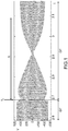
- the figures 3a and 3b represent a simulation of the method according to the present invention.
- the figures 3a and 3b represent the evolution, respectively, of the voltage V abc (vertical axis) and of the current intensity (vertical axis) as a function of time following a loss of network at an instant t 1 .
- This tilting takes place, unlike the tilting observed at the figure 1 , without major instability.
- the invention also relates to a computer program comprising instructions which, when the program is executed by a computer, lead to the implementation of the control method according to the present invention.
- the invention also relates to a DC / AC converter provided with the computer program according to the present invention.
Landscapes
- Engineering & Computer Science (AREA)
- Power Engineering (AREA)
- Control Of Eletrric Generators (AREA)
- Rectifiers (AREA)
Abstract
L'invention concerne un procédé de commande d'un convertisseur (100) DC/AC connecté à un réseau (110) électrique, le convertisseur (100) étant commandé par une loi de commande (200) configurée pour imposer au convertisseur (100) qu'il fonctionne, par défaut, en mode source de courant, et en cas de disparition du réseau (110) électrique, commande le basculement, dudit convertisseur (100), du mode source de courant vers un mode générateur synchrone virtuel, la loi de commande (200) étant également configurée pour, tant que le convertisseur (100) fonctionne en mode source de courant, surveiller la fréquence et la phase du réseau (110) électrique permettant d'initialiser l'émulation du mode générateur synchrone virtuel, par ladite loi de commande (200), au moment d'une détection de la disparition du réseau (110) électrique.The invention relates to a method for controlling a DC / AC converter (100) connected to an electrical network (110), the converter (100) being controlled by a control law (200) configured to impose on the converter (100) that it operates, by default, in current source mode, and in the event of the disappearance of the electrical network (110), controls the switching of said converter (100) from current source mode to virtual synchronous generator mode, the law control (200) being also configured for, as long as the converter (100) is operating in current source mode, monitoring the frequency and phase of the electrical network (110) making it possible to initiate the emulation of the virtual synchronous generator mode, by said control law (200) at the time of detection of the disappearance of the electrical network (110).
Description
La présente invention concerne un procédé de commande d'un convertisseur DC/AC. En particulier, la présente invention concerne un procédé de commande d'un convertisseur permettant de faire basculer ce dernier d'un mode source de courant vers un mode conforme à celui d'un générateur synchrone virtuel.The present invention relates to a method for controlling a DC / AC converter. In particular, the present invention relates to a method for controlling a converter making it possible to switch the latter from a current source mode to a mode conforming to that of a virtual synchronous generator.
Les convertisseurs DC/AC sont aujourd'hui largement utilisés dans les réseaux de distribution électrique. Leur mise en œuvre est notamment imposée par l'émergence des sources d'énergie non conventionnelles telles que les sources d'énergie renouvelable, mais également par la mise en œuvre de réserves primaires telles que les batteries ou encore les volants d'inertie (« Fly Wheel » selon la terminologie Anglo-Saxonne).DC / AC converters are widely used today in power distribution networks. Their implementation is notably imposed by the emergence of unconventional energy sources such as renewable energy sources, but also by the implementation of primary reserves such as batteries or even flywheels (" Fly Wheel ”according to Anglo-Saxon terminology).
Ces convertisseurs peuvent fonctionner en mode source de courant (« Grid-tie » selon la terminologie Anglo-Saxonne).These converters can operate in current source mode (“Grid-tie” according to Anglo-Saxon terminology).
Plus particulièrement, selon ce mode de fonctionnement, dès lors qu'un convertisseur est connecté à un réseau de distribution électrique, il se synchronise au réseau de distribution électrique via une boucle à verrouillage de phase (« PLL » ou « Phase Lock Loop » selon la terminologie Anglo-Saxonne), et lui fournit une puissance active P et une puissance réactive Q régulées via une boucle de contrôle de puissance (« Power Control Loop » selon la terminologie Anglo-Saxonne) et sur la base de la tension V et de la fréquence F du réseau de distribution électrique.More particularly, according to this operating mode, when a converter is connected to an electrical distribution network, it is synchronized with the electrical distribution network via a phase-locked loop (“PLL” or “Phase Lock Loop” according to Anglo-Saxon terminology), and supplies it with an active power P and a reactive power Q regulated via a power control loop (“Power Control Loop” according to Anglo-Saxon terminology) and on the basis of the voltage V and of the frequency F of the electrical distribution network.
Un convertisseur fonctionnant en tant que source de courant est simple à mettre en œuvre, et procure une relative stabilité au réseau de distribution électrique.A converter operating as a current source is simple to implement, and provides relative stability to the electrical distribution network.
Toutefois, selon ce mode de fonctionnement, il n'est pas possible de recourir à un îlotage (« Islanding » selon la terminologie Anglo-Saxonne), ou de répondre à une insuffisance du réseau et notamment une disparition de ce dernier.However, according to this operating mode, it is not possible to resort to islanding (“Islanding” according to Anglo-Saxon terminology), or to respond to an insufficiency of the network and in particular a disappearance of the latter.
Afin de pallier ces inconvénients, un autre mode de contrôle du convertisseur, dit « mode source de tension » (« Grid Forming » selon la terminologie Anglo-Saxonne), peut également être mis en œuvre.In order to overcome these drawbacks, another converter control mode, called “voltage source mode” (“Grid Forming” according to Anglo-Saxon terminology), can also be implemented.
Aussi parmi les convertisseurs fonctionnant selon ce mode, les générateurs synchrones virtuels (tel que celui décrit dans le document [1] cité à la fin de la description) occupent une place de choix.Also among the converters operating according to this mode, the virtual synchronous generators (such as that described in the document [1] cited at the end of the description) occupy a place of choice.
En effet, ces derniers peuvent facilement être connectés en parallèle avec d'autres sources d'énergie telles que des groupes électrogènes, afin de se répartir les charges connectées au réseau de distribution électrique.Indeed, the latter can easily be connected in parallel with other energy sources such as generators, in order to distribute the loads connected to the electrical distribution network.
Toutefois, contrairement au mode source de courant, le mode générateur synchrone virtuel représente un certain danger pour les opérateurs, et nécessite de prendre des précautions particulières lors des opérations de maintenance.However, unlike the current source mode, the virtual synchronous generator mode represents a certain danger for operators, and requires special precautions to be taken during maintenance operations.
Ainsi, un convertisseur fonctionnant par défaut en mode source de courant, et capable de basculer vers un mode conforme à celui d'un générateur synchrone virtuel, semble être une option particulièrement intéressante afin d'assurer la stabilité du réseau tout en minimisant les risques pour les opérateurs susceptibles d'intervenir sur le convertisseur lors d'opérations de maintenance.Thus, a converter operating by default in current source mode, and capable of switching to a mode conforming to that of a virtual synchronous generator, seems to be a particularly interesting option in order to ensure the stability of the network while minimizing the risks for operators likely to work on the converter during maintenance operations.
Ce basculement du mode source de courant vers le mode générateur synchrone peut notamment intervenir à la suite d'une déconnexion volontaire (par un ilotage programmé) ou involontaire d'un réseau de distribution dit « fort » (« Infinité bus » selon la terminologie Anglo-Saxonne).This switching from current source mode to synchronous generator mode may in particular occur following a voluntary disconnection (by a programmed islanding) or involuntary disconnection of a so-called “strong” distribution network (“Infinity bus” according to Anglo terminology). -Saxonne).
Toutefois, le basculement entre ces deux modes, notamment lorsque le réseau disparait, reste problématique, et peut générer une instabilité de la tension et de la fréquence en sortie du convertisseur tel qu'illustré à la
Un but de la présente invention est donc de proposer un procédé de contrôle d'un convertisseur permettant d'éliminer les instabilités de tension et de fréquence susceptibles d'intervenir lors du basculement dudit convertisseur d'un mode source de courant vers un mode générateur synchrone virtuel.An aim of the present invention is therefore to provide a method for controlling a converter making it possible to eliminate the voltage and frequency instabilities liable to occur when switching said converter from a current source mode to a synchronous generator mode. virtual.
Un autre but de la présente invention est de proposer un procédé de contrôle d'un convertisseur permettant de garantir la sécurité des personnes opérant sur ledit convertisseur.Another aim of the present invention is to provide a method for controlling a converter making it possible to guarantee the safety of persons operating on said converter.
Les buts de l'invention sont, au moins en partie, atteints par un procédé de commande d'un convertisseur DC/AC connecté à un réseau électrique, le convertisseur étant commandé par une loi de commande configurée pour imposer au convertisseur qu'il fonctionne, par défaut, en mode source de courant, et en cas de disparition du réseau électrique, commande le basculement, dudit convertisseur, du mode source de courant vers un mode générateur synchrone virtuel, la loi de commande étant également configurée pour, tant que le convertisseur fonctionne en mode source de courant, surveiller la fréquence et la phase du réseau électrique permettant d'initialiser l'émulation du mode générateur synchrone virtuel, par ladite loi de commande, au moment d'une détection de la disparition du réseau électrique.The objects of the invention are, at least in part, achieved by a method for controlling a DC / AC converter connected to an electrical network, the converter being controlled by a control law configured to require the converter to operate. , by default, in current source mode, and in the event of disappearance of the electrical network, controls the switching of said converter from current source mode to a virtual synchronous generator mode, the control law also being configured for, as long as the converter operates in current source mode, monitoring the frequency and phase of the electrical network making it possible to initialize the emulation of the virtual synchronous generator mode, by said control law, at the time of detection of the disappearance of the electrical network.
Selon un mode de mise en œuvre, la loi de commande comprend deux routines dites, respectivement, routine source de courant et routine générateur synchrone mettant en œuvre, respectivement la commande en mode source de courant et la commande en mode générateur synchrone virtuel du convertisseur.According to one mode of implementation, the control law comprises two routines called, respectively, current source routine and synchronous generator routine implementing, respectively, the control in current source mode and the control in virtual synchronous generator mode of the converter.
Selon un mode de mise en œuvre, la routine source de courant comprend boucle à verrouillage de phase qui, à partir de la fréquence et de l'angle du réseau calcul, permet de synchroniser, en termes de phase et d'angle de phase, le courant délivré par le convertisseur au réseau électrique.According to one embodiment, the current source routine comprises phase locked loop which, from the frequency and the angle of the calculation network, makes it possible to synchronize, in terms of phase and phase angle, the current delivered by the converter to the electrical network.
Selon un mode de mise en œuvre, la routine source de courant comprend également une boucle de contrôle de puissance destinée à estimer un courant de référence que le convertisseur doit délivrer en fonction d'une puissance active P et une puissance réactive Q nécessaires au fonctionnement du réseau électrique.According to one mode of implementation, the current source routine also includes a power control loop intended to estimate a reference current that the converter must deliver as a function of an active power P and a reactive power Q necessary for the operation of the device. electrical network.
Selon un mode de mise en œuvre, la routine générateur synchrone calcule en permanence un courant de référence, une tension de référence compatibles avec le fonctionnement d'un générateur synchrone configuré pour former le réseau.According to one mode of implementation, the synchronous generator routine continuously calculates a reference current, a reference voltage compatible with the operation of a synchronous generator configured to form the network.
Notamment le courant de référence est un courant qu'un générateur synchrone fournirait s'il était soumis à la tension mesurée au niveau des bornes de sortie dudit convertisseur.In particular, the reference current is a current that a synchronous generator would supply if it were subjected to the voltage measured at the output terminals of said converter.
Selon un mode de mise en œuvre, la fréquence et la phase du réseau surveillées par la loi de commande sont mise en œuvre pour synchroniser la tension de référence et le courant de référence calculés par la routine générateur synchrone.According to one mode of implementation, the frequency and phase of the network monitored by the control law are implemented to synchronize the reference voltage and the reference current calculated by the synchronous generator routine.
Selon un mode de mise en œuvre, la loi de commande comprend en outre un module de gestion de basculement qui, par défaut, impose une commande du convertisseur par la routine source de courant, et dès qu'une disparition du réseau intervient, impose une commande du convertisseur par la routine générateur synchrone.According to one mode of implementation, the control law further comprises a changeover management module which, by default, imposes control of the converter by the current source routine, and as soon as the network disappears, imposes a control of the converter by the synchronous generator routine.
L'invention concerne également un programme d'ordinateur comprenant des instructions qui, lorsque le programme est exécuté par un ordinateur, conduisent à mettre en œuvre le procédé de commande selon la présente invention.The invention also relates to a computer program comprising instructions which, when the program is executed by a computer, lead to the implementation of the control method according to the present invention.
L'invention concerne également un convertisseur de courant continu en courant alternatif pourvu du programme d'ordinateur selon la présente invention.The invention also relates to a direct current to alternating current converter provided with the computer program according to the present invention.
D'autres caractéristiques et avantages apparaîtrons dans la description qui va suivre des modes de mise en œuvre du procédé de commande d'un convertisseur DC/AC selon l'invention, donnés à titre d'exemples non limitatifs, en référence aux dessins annexés dans lesquels :
- la
figure 1 est une représentation graphique de la tension V (axe vertical, en « Volt ») en fonction du temps t (axe horizontal, en « s »), notamment, lafigure 1 représente l'effet du basculement au temps t1 d'un mode source de courant (zone « GT ») vers un mode générateur synchrone virtuel (zone « GF ») d'un convertisseur selon un procédé de commande connu de l'état de la technique, la zone A délimite une période temporelle associée à une instabilité de la tension ; - la
figure 2 est une représentation en modules fonctionnels d'un convertisseur selon la présente invention ; - les
figures 3a et 3b illustrent l'évolution, respectivement, de la tension Vabc (axe vertical) et de l'intensité du courant (axe vertical) en fonction du temps à la suite d'une perte de réseau à un instant t1.
- the
figure 1 is a graphical representation of the voltage V (vertical axis, in "Volt") as a function of time t (horizontal axis, in "s"), in particular, thefigure 1 represents the effect of switching at time t 1 from a current source mode ("GT" zone) to a virtual synchronous generator mode ("GF" zone) of a converter according to a known control method of the state of technically, zone A delimits a time period associated with voltage instability; - the
figure 2 is a representation in functional modules of a converter according to the present invention; - the
figures 3a and 3b illustrate the evolution, respectively, of the voltage V abc (vertical axis) and of the intensity of the current (vertical axis) as a function of time following a loss of network at an instant t 1 .
L'invention concerne un procédé de commande d'un convertisseur DC/AC (ci-après « convertisseur »). Plus particulièrement, l'invention concerne un procédé de commande d'un convertisseur permettant de faire basculer ce dernier d'un mode source de courant vers un mode conforme à celui d'un générateur synchrone virtuel.The invention relates to a method for controlling a DC / AC converter (hereinafter “converter”). More particularly, the invention relates to a method for controlling a converter making it possible to switch the latter from a current source mode to a mode conforming to that of a virtual synchronous generator.
Selon la présente invention, le convertisseur peut être un convertisseur de courant continu en courant alternatif ou un convertisseur de tension continue en tension alternative. La suite de la description sera toutefois limitée la mise en œuvre d'un convertisseur de tension.According to the present invention, the converter may be a direct current to alternating current converter or a direct voltage to alternating voltage converter. The remainder of the description will however be limited to the use of a voltage converter.
Le procédé de commande est exécuté par une loi de commande qui impose, par défaut, au convertisseur de fonctionner en mode source de courant, et en cas de disparition du réseau électrique, notamment un réseau électrique fort, commande le basculement du mode source courant vers le mode générateur synchrone virtuel.The control method is executed by a control law which, by default, requires the converter to operate in current source mode, and in the event of the disappearance of the electrical network, in particular a strong electrical network, controls the switching from the current source mode to virtual synchronous generator mode.
La loi de commande est par ailleurs configurée pour surveiller en permanence la fréquence et la phase du réseau, et émuler, à partir de ces données le mode générateur synchrone virtuel. Cette émulation, exécutée en tâche de fond lorsque le convertisseur fonctionne en mode source de courant, permet de basculer, sans interruption de puissance pour la ou les charge électriques du mode source de courant vers le mode générateur synchrone virtuel dès lors qu'une défaillance du réseau ou qu'un îlotage de ce dernier survient.The control law is also configured to continuously monitor the frequency and phase of the network, and to emulate, from these data, the virtual synchronous generator mode. This emulation, executed in the background when the converter is operating in current source mode, makes it possible to switch without power interruption for the electrical load (s) from current source mode to virtual synchronous generator mode when a failure of the network or that islanding of the latter occurs.
La
Le convertisseur 100 est connecté à un réseau de distribution électrique 110 soumis à une tension V de fréquence « f » et d'angle de phase « α » (ci-après « la phase α »), imposés par une ou plusieurs source(s) de tension susceptibles de former le réseau.The
Le convertisseur 100 convertit la tension continue générée par une source d'énergie 120 en une tension alternative.The
La source d'énergie 120 peut comprendre une source de tension continue. Une source de tension continue peut comprendre, par exemple, des panneaux photovoltaïques, des éoliennes, des hydroliennes, des machines thermodynamiques, des batteries ou encore des volants d'inertie.The
Le convertisseur 100 peut comprendre, dans le cas d'un onduleur à trois niveaux, deux condensateurs C+ et C- connectés entre eux en série pour former un condensateur équivalent C. Les bornes du condensateur équivalent C sont électriquement connectées, par exemple en parallèle aux bornes de la source d'énergie 120.The
La mise en œuvre des deux condensateurs C+ et C- permet de garantir une forme sinusoïdale non déformée du courant fourni par le convertisseur 100 au réseau de distribution électrique. L'invention n'est cependant pas limitée à l'utilisation d'un onduleur à trois niveaux.The use of the two capacitors C + and C - makes it possible to guarantee an undeformed sinusoidal shape of the current supplied by the
Le fonctionnement du convertisseur 100 est régit par une loi de commande 200.The operation of the
La loi de commande 200 impose notamment au convertisseur qu'il fonctionne par défaut en mode source de courant (« Grid Tie » selon la terminologie Anglo-Saxonne).The
En d'autres termes, selon ce mode de fonctionnement, le convertisseur 100 est soumis à la fréquence f et l'angle de phase α imposés par le réseau 110.In other words, according to this operating mode, the
Par «fréquence f et angle de phase α du réseau », on entend la fréquence et la phase de la tension du réseau de distribution électrique 110.By "frequency f and phase angle α of the network" is meant the frequency and phase of the voltage of the
La loi de commande 200 peut, à cet égard, comprendre une routine dédiée à ce mode de fonctionnement, dite routine source de courant 300.The
La routine source de courant 300 peut en particulier comprendre un module de Park 310, un module PLL 320 (PLL pour boucle à verrouillage de phase), un module de calcul de phase du réseau 330 et un module PCL 340 (PCL pour boucle de contrôle de puissance).The
Le module de Park 310 est notamment dédié au suivi de la tension Vabc du réseau, et dont la fréquence f et la phase α sont extraites, respectivement, par le module PLL 320 et le module de calcul 330.The
Notamment, le module de Park 310 a pour fonction de transformer les tensions, par exemple les trois tensions alternatives Vabc du réseau 110, en deux tensions continues Vdq qui sont utilisées par les modules 320 et 330 pour estimer respectivement la fréquence et la phase du réseau 110.In particular, the function of the
Le module PCL calcule un courant de référence Iref,GT associé à une puissance active Pref et une puissance réactive Qref que le convertisseur 100 doit délivrer au réseau de distribution électrique 110.The PCL module calculates a reference current I ref, GT associated with an active power P ref and a reactive power Q ref that the
La loi de commande 200 comprend également une routine de régulation de courant 400 pourvue d'un module de régulation de courant 410 et d'un module de génération d'impulsion 420 (« PWM » ou « Pulsation Width Modulation) selon la terminologie Anglo-Saxonne)The
Notamment, le module de génération d'impulsion 420 impose au convertisseur 100 d'appliquer des rapports cycliques, calculés par le module de régulation de courant 410, et permettant audit convertisseur de délivrer au réseau de distribution électrique le courant Iref,GT à la fréquence f et à la phase α du réseau 110.In particular, the
La loi de commande 200 est également adaptée pour imposer un basculement du mode source de courant vers un mode générateur synchrone virtuel en cas de disparition du réseau.The
La « disparition du réseau » peut par exemple survenir à la suite d'une défaillance du ce denier ou d'un ilotage, par exemple un ilotage programmé.The “disappearance of the network” can for example occur following a failure of this denier or of an islanding, for example a programmed islanding.
Selon la présente invention et tel que décrit dans le document [1] cité à la fin de la description, le mode générateur synchrone est un mode pour lequel le convertisseur se comporte comme un groupe électrogène.According to the present invention and as described in document [1] cited at the end of the description, the synchronous generator mode is a mode in which the converter behaves like a generator set.
À cet égard, la loi de commande 200 peut comprendre une routine dédiée à ce mode de fonctionnement, dite routine générateur synchrone 500.In this regard, the
Un groupe électrogène comprend généralement un rotor entraîné en rotation dans un stator et un régulateur de tension automatique (« AVR » ou « Automatic Voltage Regulator » selon la terminologie Anglo-Saxonne) agissant sur les enroulements rotoriques du rotor. Le régulateur de tension automatique applique, ainsi, une tension sur les enroulements rotoriques en fonction de la tension efficace Vrms (de la tension V) délivrés par le stator (par le groupe électrogène) sur le réseau. Le contrôle par statisme tension/puissance réactive Q permet au groupe électrogène d'adapter la tension efficace Vrms qu'il délivre en fonction de la puissance électrique réactive Q qu'il fournit.A generator set generally comprises a rotor driven in rotation in a stator and an automatic voltage regulator (“AVR” or “Automatic Voltage Regulator” according to Anglo-Saxon terminology) acting on the rotor windings of the rotor. The automatic voltage regulator thus applies a voltage to the rotor windings as a function of the effective voltage V rms (of the voltage V) delivered by the stator (by the generator set) to the network. The voltage / reactive power droop control Q allows the generator set to adapt the effective voltage V rms that it delivers as a function of the reactive electric power Q that it supplies.
Par ailleurs, le rotor d'un groupe électrogène est généralement entraîné en rotation, par un arbre d'un moteur thermique (par exemple un moteur diesel), à l'intérieur d'un stator. De par sa conception, le groupe électrogène est capable de former le réseau. Autrement dit, le groupe électrogène peut imposer la tension V et la fréquence f à un réseau électrique.Furthermore, the rotor of a generator set is generally driven in rotation, by a shaft of a heat engine (for example a diesel engine), inside a stator. By design, the generator set is capable of forming the network. In other words, the generator set can impose the voltage V and the frequency f on an electrical network.
Selon la présente invention, la routine générateur synchrone 500 comprend des modules 540 et 550, décrits plus en détails dans la suite de la description, qui génèrent, respectivement, en permanence la fréquence f et la phase α du réseau. Plus particulièrement, les modules 540 et 550 sont en permanence initialisés à la fréquence et la tension du réseau en coopération avec un module de gestion de basculement 600. Cette initialisation des modules 540 et 550 permet par ailleurs de calculer un courant de référence Iref,GF, qu'un groupe électrogène capable de former le réseau délivrerait.According to the present invention, the
Ces paramètres ne sont toutefois communiqués à la routine de régulation de courant 400 tant que le convertisseur 100 fonctionne en mode source de courant. En d'autres termes, les modules 540 et 550 de la routine générateur synchrone 500 tournent en tâche de fond tant qu'aucune défaillance du réseau n'est détectée ou qu'aucun ordre d'îlotage n'est émis. En particulier, ces modules 540 et 550 sont constamment initialisés à la fréquence et à l'angle du réseau.However, these parameters are not communicated to the
Ainsi, dès qu'une défaillance du réseau de distribution électrique 110, survient, la routine générateur synchrone 500 prend le relais sur la routine source de courant 300 de manière quasi-instantanée et impose au convertisseur 100 un comportement de générateur synchrone de sorte que ce dernier soit en mesure de former le réseau.Thus, as soon as a failure of the
En d'autres termes, dès lors que le convertisseur est connecté au réseau, et quel que soit le mode de fonctionnement du convertisseur, la routine générateur synchrone 500 calcule en permanence le courant Iref,GF.In other words, once the converter is connected to the network, and whatever the operating mode of the converter, the
Ce basculement du mode source de courant vers le mode générateur synchrone peut être commandé par un module de gestion de basculement 600 qui impose par défaut la commande du convertisseur par la routine source de courant et, en cas de défaillance du réseau, impose la commande du convertisseur par la routine générateur synchrone.This switching from the current source mode to the synchronous generator mode can be controlled by a
Le module de gestion de basculement 600 permet ainsi d'initialiser en permanence et correctement les états internes de la commande par la routine générateur synchrone 500 de sorte que ce dernier soit « prêt » au moment du basculement du mode source de courant vers le mode générateur synchrone virtuel. Ainsi selon la présente invention, il est possible de limiter les effets transitoires sur le courant et la tension lors du basculement.The
La routine générateur synchrone 500 peut, conformément au générateur synchrone virtuel décrit dans le document [1] cité à la fin de la description, comprendre un module AVR 510 (AVR pour régulateur de tension automatique), un module governor 520, un module machine synchrone 530, le module équations mécaniques 540 et le module de calcul d'angle interne de la machine synchrone 550, un module de limitation de courant 560.The
Le module AVR 510 est notamment destiné à réguler la tension aux bornes de sortie du convertisseur 100.The
Le module governor 520 est destiné à réguler la fréquence du courant susceptible d'être délivré par le convertisseur.The
Le module machine synchrone 530 comprend l'ensemble des équations différentielles relatives au fonctionnement électrique d'une machine synchrone qui est un composant d'un groupe électrogène.The
Le module équation mécanique 540 comprend les équations mécaniques d'un arbre tournant.The
Le procédé selon la présente invention permet donc de limiter les effets transitoires dus au basculement du mode source de courant vers le mode générateur synchrone virtuel.The method according to the present invention therefore makes it possible to limit the transient effects due to the switching from the current source mode to the virtual synchronous generator mode.
À titre d'illustration, les
En particulier, les
Sur ces figures, avant l'instant t1, le convertisseur est commandé par la routine source de courant. À la suite d'une perte de réseau à l'instant t1, un basculement de la commande du convertisseur de la routine source de courant vers la routine générateur synchrone s'opère.In these figures, before time t 1 , the converter is controlled by the current source routine. Following a loss of network at time t 1 , a switchover of the converter control from the current source routine to the synchronous generator routine takes place.
Ce basculement s'effectue, contrairement au basculement observé à la
L'invention concerne également un programme d'ordinateur comprenant des instructions qui, lorsque le programme est exécuté par un ordinateur, conduisent à mettre en œuvre le procédé de commande selon la présente invention.The invention also relates to a computer program comprising instructions which, when the program is executed by a computer, lead to the implementation of the control method according to the present invention.
L'invention concerne également un convertisseur DC/AC pourvu du programme d'ordinateur selon la présente invention.The invention also relates to a DC / AC converter provided with the computer program according to the present invention.
-
[1]
EP 3208907 EP 3208907
Claims (10)
Applications Claiming Priority (1)
| Application Number | Priority Date | Filing Date | Title |
|---|---|---|---|
| FR1904362A FR3095559A1 (en) | 2019-04-25 | 2019-04-25 | PROCESS FOR CONTROLLING A DC / AC CONVERTER |
Publications (1)
| Publication Number | Publication Date |
|---|---|
| EP3731398A1 true EP3731398A1 (en) | 2020-10-28 |
Family
ID=67956974
Family Applications (1)
| Application Number | Title | Priority Date | Filing Date |
|---|---|---|---|
| EP20170412.9A Ceased EP3731398A1 (en) | 2019-04-25 | 2020-04-20 | Method for controlling a dc/ac converter |
Country Status (4)
| Country | Link |
|---|---|
| US (1) | US11394314B2 (en) |
| EP (1) | EP3731398A1 (en) |
| CN (1) | CN111864792A (en) |
| FR (1) | FR3095559A1 (en) |
Cited By (1)
| Publication number | Priority date | Publication date | Assignee | Title |
|---|---|---|---|---|
| CN114024309A (en) * | 2021-11-11 | 2022-02-08 | 广东志成冠军集团有限公司 | Island micro-grid system and interactive oscillation suppression method and system thereof |
Citations (3)
| Publication number | Priority date | Publication date | Assignee | Title |
|---|---|---|---|---|
| EP3208907A1 (en) | 2016-02-16 | 2017-08-23 | Schneider Electric Industries SAS | Method for controlling a virtual generator |
| CN104410097B (en) * | 2014-09-26 | 2018-07-06 | 广东易事特电源股份有限公司 | Microgrid inverter and its grid-connected and off-grid control method |
| CN109494800A (en) * | 2018-12-19 | 2019-03-19 | 上海电气分布式能源科技有限公司 | The control method and system that grid-connected and off-network for micro-capacitance sensor mutually switches |
Family Cites Families (2)
| Publication number | Priority date | Publication date | Assignee | Title |
|---|---|---|---|---|
| US8606424B2 (en) * | 2011-04-05 | 2013-12-10 | King Fahd University Of Petroleum And Minerals | Particle swarm optimization system and method for microgrids |
| US8957546B2 (en) * | 2012-07-10 | 2015-02-17 | Nixon Power Services, Llc | Electrical cogeneration system and method |
-
2019
- 2019-04-25 FR FR1904362A patent/FR3095559A1/en active Pending
-
2020
- 2020-04-02 US US16/838,794 patent/US11394314B2/en active Active
- 2020-04-17 CN CN202010303944.1A patent/CN111864792A/en active Pending
- 2020-04-20 EP EP20170412.9A patent/EP3731398A1/en not_active Ceased
Patent Citations (3)
| Publication number | Priority date | Publication date | Assignee | Title |
|---|---|---|---|---|
| CN104410097B (en) * | 2014-09-26 | 2018-07-06 | 广东易事特电源股份有限公司 | Microgrid inverter and its grid-connected and off-grid control method |
| EP3208907A1 (en) | 2016-02-16 | 2017-08-23 | Schneider Electric Industries SAS | Method for controlling a virtual generator |
| CN109494800A (en) * | 2018-12-19 | 2019-03-19 | 上海电气分布式能源科技有限公司 | The control method and system that grid-connected and off-network for micro-capacitance sensor mutually switches |
Non-Patent Citations (2)
| Title |
|---|
| "Microgrid Technology and Engineering Application", 14 September 2015, ELSEVIER SCIENCE & TECHNOLOGY, U.S.A., ISBN: 978-0-12-803630-3, article LI FUSHENG ET AL: "P/Q control", pages: 19 - 20, XP055655905 * |
| BEVRANI HASSAN ET AL: "Virtual synchronous generators: A survey and new perspectives", INTERNATIONAL JOURNAL OF ELECTRICAL POWER & ENERGY SYSTEMS, JORDAN HILL, OXFORD, GB, vol. 54, 7 August 2013 (2013-08-07), pages 244 - 254, XP028727167, ISSN: 0142-0615, DOI: 10.1016/J.IJEPES.2013.07.009 * |
Cited By (2)
| Publication number | Priority date | Publication date | Assignee | Title |
|---|---|---|---|---|
| CN114024309A (en) * | 2021-11-11 | 2022-02-08 | 广东志成冠军集团有限公司 | Island micro-grid system and interactive oscillation suppression method and system thereof |
| CN114024309B (en) * | 2021-11-11 | 2023-12-05 | 广东志成冠军集团有限公司 | Island micro-grid system and method and system for restraining interaction oscillation thereof |
Also Published As
| Publication number | Publication date |
|---|---|
| FR3095559A1 (en) | 2020-10-30 |
| CN111864792A (en) | 2020-10-30 |
| US11394314B2 (en) | 2022-07-19 |
| US20200343825A1 (en) | 2020-10-29 |
Similar Documents
| Publication | Publication Date | Title |
|---|---|---|
| EP2853693B1 (en) | Method and module for protecting against torque peaks between a motor and an electric machine | |
| EP3185386B1 (en) | Method for controlling a micro-network for electricity distribution | |
| KR102607778B1 (en) | black start restoration | |
| US8093740B2 (en) | Wind power generation system and operation method thereof | |
| CA2754643C (en) | Method for operating a wind turbine | |
| EP3208907A1 (en) | Method for controlling a virtual generator | |
| US20170159577A1 (en) | Gas Turbine Combined Electric Power Generation Apparatus | |
| JP2019528667A (en) | Wind turbine control method | |
| US20220364546A1 (en) | Providing auxiliary power using offshore wind turbines | |
| WO2017025664A1 (en) | Auxiliary system for storage and supply of electrical energy for multiple uses incorporated in an electricity production plant | |
| CN110226274B (en) | Providing auxiliary power when a high voltage link is not functioning | |
| JP6951436B2 (en) | Controlling power exchange from self-excited transducers | |
| EP3731398A1 (en) | Method for controlling a dc/ac converter | |
| WO2018200178A1 (en) | Method and system for enhancing electrical power production by a power generation system | |
| Battaiotto et al. | Stand-alone hybrid microgrid for remote areas. Topology and operation strategy | |
| Lyu et al. | Unified grid-forming control of pmsg wind turbines for fast frequency response and MPPT | |
| US20190214827A1 (en) | Systems and methods for rapid activation and synchronization of dispatchable power sources | |
| EP3627649B1 (en) | Method for controlling a generator | |
| KR20200108553A (en) | Apparatus for controlling power generator, Apparatus for controlling energy storage system, and Cooperative control system including them | |
| CN115822874A (en) | System and method for converter control of inverter-based resources | |
| EP3804073A1 (en) | System for synchronising energy sources coupled to an aircraft | |
| FR3095195A1 (en) | CONTROL PROCEDURE FOR AN AIRCRAFT ELECTRICAL POWER SUPPLY NETWORK | |
| AU2014200885B2 (en) | Method for operating a wind turbine | |
| EP3672011B1 (en) | Method for regulating an electricity distribution network | |
| Moraco et al. | Comparative Evaluation of Methods for Switching Temporary Frequency Support in Islanded Systems |
Legal Events
| Date | Code | Title | Description |
|---|---|---|---|
| PUAI | Public reference made under article 153(3) epc to a published international application that has entered the european phase |
Free format text: ORIGINAL CODE: 0009012 |
|
| STAA | Information on the status of an ep patent application or granted ep patent |
Free format text: STATUS: THE APPLICATION HAS BEEN PUBLISHED |
|
| AK | Designated contracting states |
Kind code of ref document: A1 Designated state(s): AL AT BE BG CH CY CZ DE DK EE ES FI FR GB GR HR HU IE IS IT LI LT LU LV MC MK MT NL NO PL PT RO RS SE SI SK SM TR |
|
| AX | Request for extension of the european patent |
Extension state: BA ME |
|
| STAA | Information on the status of an ep patent application or granted ep patent |
Free format text: STATUS: REQUEST FOR EXAMINATION WAS MADE |
|
| 17P | Request for examination filed |
Effective date: 20210426 |
|
| RBV | Designated contracting states (corrected) |
Designated state(s): AL AT BE BG CH CY CZ DE DK EE ES FI FR GB GR HR HU IE IS IT LI LT LU LV MC MK MT NL NO PL PT RO RS SE SI SK SM TR |
|
| STAA | Information on the status of an ep patent application or granted ep patent |
Free format text: STATUS: EXAMINATION IS IN PROGRESS |
|
| 17Q | First examination report despatched |
Effective date: 20220318 |
|
| STAA | Information on the status of an ep patent application or granted ep patent |
Free format text: STATUS: THE APPLICATION HAS BEEN REFUSED |
|
| 18R | Application refused |
Effective date: 20231222 |