EP3729142B1 - A radiation detector - Google Patents
A radiation detector Download PDFInfo
- Publication number
- EP3729142B1 EP3729142B1 EP18833116.9A EP18833116A EP3729142B1 EP 3729142 B1 EP3729142 B1 EP 3729142B1 EP 18833116 A EP18833116 A EP 18833116A EP 3729142 B1 EP3729142 B1 EP 3729142B1
- Authority
- EP
- European Patent Office
- Prior art keywords
- ionisation
- main bodies
- fractionation apparatus
- ionisation chambers
- chambers
- Prior art date
- Legal status (The legal status is an assumption and is not a legal conclusion. Google has not performed a legal analysis and makes no representation as to the accuracy of the status listed.)
- Active
Links
- 230000005855 radiation Effects 0.000 title claims description 20
- 238000005259 measurement Methods 0.000 claims description 28
- 238000005194 fractionation Methods 0.000 claims description 20
- 229940121896 radiopharmaceutical Drugs 0.000 claims description 11
- 239000012217 radiopharmaceutical Substances 0.000 claims description 11
- 230000002799 radiopharmaceutical effect Effects 0.000 claims description 11
- FAPWRFPIFSIZLT-UHFFFAOYSA-M Sodium chloride Chemical compound [Na+].[Cl-] FAPWRFPIFSIZLT-UHFFFAOYSA-M 0.000 claims description 2
- 239000007789 gas Substances 0.000 description 13
- 230000002285 radioactive effect Effects 0.000 description 9
- 238000001514 detection method Methods 0.000 description 6
- 230000008901 benefit Effects 0.000 description 4
- 238000009206 nuclear medicine Methods 0.000 description 4
- 238000000034 method Methods 0.000 description 3
- XKRFYHLGVUSROY-UHFFFAOYSA-N Argon Chemical compound [Ar] XKRFYHLGVUSROY-UHFFFAOYSA-N 0.000 description 2
- 230000000694 effects Effects 0.000 description 2
- 239000007788 liquid Substances 0.000 description 2
- 238000012544 monitoring process Methods 0.000 description 2
- 230000009467 reduction Effects 0.000 description 2
- 206010073306 Exposure to radiation Diseases 0.000 description 1
- 229910052778 Plutonium Inorganic materials 0.000 description 1
- 230000003321 amplification Effects 0.000 description 1
- 238000004458 analytical method Methods 0.000 description 1
- 229910052786 argon Inorganic materials 0.000 description 1
- 230000008859 change Effects 0.000 description 1
- 238000000605 extraction Methods 0.000 description 1
- 230000003993 interaction Effects 0.000 description 1
- 238000011835 investigation Methods 0.000 description 1
- 150000002500 ions Chemical class 0.000 description 1
- 238000013178 mathematical model Methods 0.000 description 1
- 238000003199 nucleic acid amplification method Methods 0.000 description 1
- 239000002245 particle Substances 0.000 description 1
- OYEHPCDNVJXUIW-UHFFFAOYSA-N plutonium atom Chemical compound [Pu] OYEHPCDNVJXUIW-UHFFFAOYSA-N 0.000 description 1
- 238000002360 preparation method Methods 0.000 description 1
- 230000008569 process Effects 0.000 description 1
- 239000000941 radioactive substance Substances 0.000 description 1
- 239000007787 solid Substances 0.000 description 1
- 239000000126 substance Substances 0.000 description 1
- 239000002699 waste material Substances 0.000 description 1
Images
Classifications
-
- G—PHYSICS
- G01—MEASURING; TESTING
- G01T—MEASUREMENT OF NUCLEAR OR X-RADIATION
- G01T1/00—Measuring X-radiation, gamma radiation, corpuscular radiation, or cosmic radiation
- G01T1/16—Measuring radiation intensity
- G01T1/185—Measuring radiation intensity with ionisation chamber arrangements
-
- A—HUMAN NECESSITIES
- A61—MEDICAL OR VETERINARY SCIENCE; HYGIENE
- A61K—PREPARATIONS FOR MEDICAL, DENTAL OR TOILETRY PURPOSES
- A61K51/00—Preparations containing radioactive substances for use in therapy or testing in vivo
-
- A—HUMAN NECESSITIES
- A61—MEDICAL OR VETERINARY SCIENCE; HYGIENE
- A61N—ELECTROTHERAPY; MAGNETOTHERAPY; RADIATION THERAPY; ULTRASOUND THERAPY
- A61N5/00—Radiation therapy
- A61N5/10—X-ray therapy; Gamma-ray therapy; Particle-irradiation therapy
- A61N5/1001—X-ray therapy; Gamma-ray therapy; Particle-irradiation therapy using radiation sources introduced into or applied onto the body; brachytherapy
- A61N2005/1019—Sources therefor
- A61N2005/1021—Radioactive fluid
-
- A—HUMAN NECESSITIES
- A61—MEDICAL OR VETERINARY SCIENCE; HYGIENE
- A61N—ELECTROTHERAPY; MAGNETOTHERAPY; RADIATION THERAPY; ULTRASOUND THERAPY
- A61N5/00—Radiation therapy
- A61N5/10—X-ray therapy; Gamma-ray therapy; Particle-irradiation therapy
- A61N2005/1092—Details
- A61N2005/1094—Shielding, protecting against radiation
Definitions
- the present invention relates to a fractionation apparatus.
- a preferred, but non-exclusive use of the fractionation apparatus according to the invention is in the field of nuclear medicine.
- So-called “fractionation apparatus” that is, machines capable of fractionating a radioactive substance into different doses for patients, are among the machines most widely used in nuclear medicine. These machines, starting from a main "bulk” container which contains a sufficient amount of a radiopharmaceutical for various doses, are capable of drawing from the bulk container a pre-determined amount of a radiopharmaceutical, or dose. The dose is introduced into a syringe or a single-dose vial, ready for use.
- dose fractionation apparatus make use of radioactivity measuring devices commonly called “dose calibrators”. These devices mainly consist of an ionisation chamber coupled with an electronic measuring instrument (“electrometer”) and a control console with display of measurement data.
- dose calibrators radioactivity measuring devices commonly called “dose calibrators”. These devices mainly consist of an ionisation chamber coupled with an electronic measuring instrument (“electrometer”) and a control console with display of measurement data.
- the ionisation chamber has a well-type conformation, i.e. it is in the form of a relatively deep cylindrical cavity in which the radioactive source to be measured is introduced from above.
- the calibrator must enable a sufficient measuring efficiency.
- the well-type configuration makes it possible to surround the source with the detector, thus increasing the measuring efficiency.
- the loss of efficiency is in fact due to the solid angle (with the centre located in the radiation source) which subtends the hole for the introduction of the radioactive source.
- the calibrator must minimise, within acceptable limits (about 2-5%) the error in the relative positioning between the source and the detector.
- This error lies mainly in the fact that, in the typical practice of nuclear medicine, the radioactive sources are liquids contained in syringes or vials with variable volumes and shapes.
- the well-type configuration also enables this source of error to be reduced, in particular if the longitudinal dimension of the detector is much greater than the longitudinal dimension of the source to be measured.
- the detectors are typically gas detectors, in order to ensure a low cost and considerable stability over time, it is necessary to pressurise the gas in order to increase the detection efficiency.
- the gas must be maintained under pressure (even approximately 15 bar) in the ionisation chamber and the ionisation chamber must have walls that are sufficiently "thin” to absorb as little radiation as possible (thus increasing the detection efficiency).
- the first document ( US 2002/163987 ) relates to a technique for monitoring nuclear waste, in particular for monitoring the content of plutonium, and to a neutron detector.
- the device described comprises a plurality of neutron detectors which are independent from one another, so as to enable a specific analysis of the signals of each individual detector.
- the purpose of the device is to establish the content and distribution of neutron sources within the sample.
- each detector has its own dedicated electronic amplification and discrimination system designed to measure pulses.
- the device described in the second document also comprises a series of detectors which are independent from one another and configured to detect fast neutrons.
- Each detector is provided with its own electronics for determining both the energy of the neutrons and the point of interaction inside the detector. In this case as well, the arrangement of the detectors and independence in management and measurement are necessary in order to determine the spatial distribution of the samples undergoing investigation.
- the object of the present invention is to offer a fractionation apparatus that enables the drawbacks of the currently available ionisation chambers to be overcome.
- fractionation apparatus requires considerably less overall space than the currently available chambers.
- Another advantage of the fractionation apparatus according to the present invention is that it enables a considerable flexibility of positioning within the fractionation apparatus.
- the radiation detector according to the present invention lends itself particularly well to use in a fractionation apparatus, configured for the preparation of pre-determined doses of a radiopharmaceutical.
- the detector may be located inside a shielded booth together with other known accessories, including a support for a syringe, a support for a bulk container of the radiopharmaceutical, a feed circuit for feeding the radiopharmaceutical and saline solution or other substances, and electronics for controlling and managing the various devices.
- the radiation detector according to the present invention comprises two or more ionisation chambers (10), each of which comprises a main body (11), intended to contain a measuring gas which, as is well known, ionises following exposure to radiation.
- a gas widely used to detect radiation is argon.
- Ionisation chambers (10) are configured to detect alpha, beta or gamma sources.
- the main bodies (11) are arranged in such a way as to delimit a measurement space (M) inside which a radiation source may be positioned.
- the present invention envisages the use of two or more ionisation chambers (10), arranged in such a way as to delimit a measurement space (M), whose shape and size can be selected based on the shape and size of the sources to be measured.
- the ionisation chambers (10) can be mounted on movable supports so as to enable a change in the shape of the measurement space (M), or enable an opening of the measurement space (M) and facilitate the introduction of the source to be measured along a substantially horizontal direction of access.
- the source i.e. the syringe containing the radiopharmaceutical
- the measurement space (M) not from above, as is presently the case, but from the front, i.e. along a substantially horizontal direction of access.
- this enables a considerable reduction in the size of the booth intended to contain the detector.
- the booth can be dimensioned so as to contain the detector with modest margins height-wise, since the source to be detected has to be introduced into the measurement space (M) not from above, but horizontally.
- a further advantage tied to the use of more than one ionisation chamber (10), rather than only one, is that each of them will have a relatively compact size, thus enabling them to withstand higher internal pressures with smaller wall thicknesses compared to the prior art. This results in a considerable increase in detection efficiency.
- the ionisation chambers (10) can be arranged so as to surround a measurement space (M) that is cylindrical or prismatic overall, endowed with a longitudinal axis (Y).
- the longitudinal axis (Y) is preferably vertically oriented. Examples of such an arrangement are shown in figures 2 , 4 and 5 .
- the ionisation chambers (10) can be arranged in such a way that the main bodies (11) are distributed along a closed curve (C) lying in a plane which is perpendicular to the longitudinal axis (Y).
- the ionisation chambers (10) can be arranged in such a way as to surround a cylindrical space with a circular, oval or polygonal cross section, in relation to the shape of the source to be measured, and having a vertically oriented longitudinal axis (Y).
- the overall geometry of the measurement space (M) is of the well type, as in the current devices, but the use of more than one ionisation chamber (10) allows the shape of the measurement space (M) to be varied in a way that would be otherwise impossible using a single ionisation chamber.
- the detector according to the present invention comprises a plurality of ionisation chambers (10a,10b).
- a part of the ionisation chambers (10a) is movable relative to the remaining part of the ionisation chambers (10b) between a measurement position, in which the main bodies (11) are distributed along a closed curve (C), and a service position, in which the main bodies (11) are distributed along a line or an open curve (A).
- the closed curve (C) can be of any shape and the overall geometry of the measurement space (M) is cylindrical.
- the measurement space (M) can be open so as to enable the introduction of the source along a horizontal direction, that is, not necessarily from above along the longitudinal direction of the measurement space (M), as is the case with current detectors. This means that the detector requires much less room for manoeuvre around it than is required by current detectors, which require the introduction of the source from above and thus all the space necessary for the introduction from above of the detector.
- the ionisation chambers (10) can be arranged in such a way that the main bodies (11) are distributed along an open curve (R).
- the overall geometry of the measurement space (M) is again cylindrical, or well-type, but open at the side to facilitate the introduction of the source to be measured along a horizontal direction.
- the open curve (R) can be, for example, a circumferential arc which is concentric to the longitudinal axis (Y).
- the ionisation chambers (10) can be arranged in such a way that the main bodies (11) are distributed along two rows (I, II) parallel to an alignment direction (X).
- the measurement space (M) has a prismatic geometry, and can be open at both ends (a,b) of the two rows (I, II) of ionisation chambers (10), or else at one end only.
- the source to be measured can be introduced into the measurement space (M) along a direction which is parallel to the alignment direction (X) of the ionisation chambers (10).
- the source can be introduced and extracted rectilinearly along the alignment direction (X) in one way only, that is, the source can be introduced through a first end of the measurement space (M) and be extracted from the opposite end. If the measurement space (M) is closed at one end, introduction and extraction must obviously take place through the open end.
- the main bodies (11) have a cylindrical conformation.
- This conformation offers high resistance to internal pressure, so the gas can be contained at high pressures, even 15 bar, without requiring large wall thicknesses, thus considerably improving detection efficiency.
- the longitudinal dimension, i.e. the length of the main bodies (11) can be considerably increased, enabling a further increase in detection efficiency.
- the ionisation chambers (10) can be arranged with the main cylindrical bodies (11) oriented vertically, i.e. parallel to the longitudinal axis (Y) of the measurement space (M).
- the closed curve (C), open curve (A) and parallel rows (I, II) described previously are to be understood as lying in a plane which is perpendicular to the longitudinal axis (Y) of the measurement space (M).
- the main bodies (11) are independent from each other, i.e. each main body (11) is closed and delimits a containment volume for the gas used to detect radiation.
- the main bodies (11) are connected to a manifold (15).
- the main bodies (11) and the manifold (15) delimit a closed volume for containing the measuring gas.
- the manifold (15) comprises a conduit for containing the measuring gas.
- the manifold (15) can be ring-shaped, and the main bodies (11) can be connected to the manifold (15) projecting parallel to each other.
- the manifold (15) could also have a rectilinear shape or any other shape.
- An electronic circuit can be connected to the ionisation chambers (10) in order to detect the overall ionisation of the gas and translate the detected ionisation into a radiation measurement.
- the circuit is commonly called an "electrometer”. It enables, with different circuitries, the ionisation current produced by the incident radiation in the gas to be efficiently collected.
- the electronic circuit is configured to add together the contributions of all of the ionisation chambers (10) in order to obtain a measurement of the total radiation.
- the electronic circuit is configured to integrate the ionisation current that is produced in the different ionisation chambers (10) in order to obtain a single electric signal.
- each ionisation chamber (10) comprises an anode and a cathode, maintained at a potential difference by the electrometer itself and generally comprised between 150 and 500 Volts.
- the ions produced in the gas by the radioactive particles collect at the anode or cathode depending on their charge, thus producing a current.
- the ionisation currents produced in the various ionisation chambers (10) are integrated together in order to obtain a single electrical signal.
- the current is amplified by a circuit present in the electrometer, so as to generate a signal which is proportional to the ionisation current.
- the signal is then processed in order to be sent to a control and management module of the instrument (with a user interface).
- a calibration procedure through the use of radioactive sources with known activity, enables the amplified and processed signal to be converted into units of radioactivity.
Landscapes
- Health & Medical Sciences (AREA)
- Life Sciences & Earth Sciences (AREA)
- Physics & Mathematics (AREA)
- Biomedical Technology (AREA)
- Engineering & Computer Science (AREA)
- General Health & Medical Sciences (AREA)
- Veterinary Medicine (AREA)
- Public Health (AREA)
- Animal Behavior & Ethology (AREA)
- Spectroscopy & Molecular Physics (AREA)
- High Energy & Nuclear Physics (AREA)
- Molecular Biology (AREA)
- General Physics & Mathematics (AREA)
- Nuclear Medicine, Radiotherapy & Molecular Imaging (AREA)
- Pathology (AREA)
- Radiology & Medical Imaging (AREA)
- Pharmacology & Pharmacy (AREA)
- Optics & Photonics (AREA)
- Medicinal Chemistry (AREA)
- Chemical & Material Sciences (AREA)
- Epidemiology (AREA)
- Measurement Of Radiation (AREA)
- Electron Tubes For Measurement (AREA)
Description
- The present invention relates to a fractionation apparatus. A preferred, but non-exclusive use of the fractionation apparatus according to the invention is in the field of nuclear medicine.
- So-called "fractionation apparatus", that is, machines capable of fractionating a radioactive substance into different doses for patients, are among the machines most widely used in nuclear medicine. These machines, starting from a main "bulk" container which contains a sufficient amount of a radiopharmaceutical for various doses, are capable of drawing from the bulk container a pre-determined amount of a radiopharmaceutical, or dose. The dose is introduced into a syringe or a single-dose vial, ready for use.
- For the purpose of the fractionation process, dose fractionation apparatus make use of radioactivity measuring devices commonly called "dose calibrators". These devices mainly consist of an ionisation chamber coupled with an electronic measuring instrument ("electrometer") and a control console with display of measurement data.
- The task of such instruments/devices is to measure the activity contained in a syringe or in a vial with very high precision, which tends to be within ±2%.
- In order to enable the necessary measuring precision, the ionisation chamber has a well-type conformation, i.e. it is in the form of a relatively deep cylindrical cavity in which the radioactive source to be measured is introduced from above.
- The necessity of having a deep well is due to the following fundamental metrological needs.
- First of all, the calibrator must enable a sufficient measuring efficiency. The well-type configuration makes it possible to surround the source with the detector, thus increasing the measuring efficiency. The loss of efficiency is in fact due to the solid angle (with the centre located in the radiation source) which subtends the hole for the introduction of the radioactive source.
- Secondly, the calibrator must minimise, within acceptable limits (about 2-5%) the error in the relative positioning between the source and the detector. This error lies mainly in the fact that, in the typical practice of nuclear medicine, the radioactive sources are liquids contained in syringes or vials with variable volumes and shapes. The well-type configuration also enables this source of error to be reduced, in particular if the longitudinal dimension of the detector is much greater than the longitudinal dimension of the source to be measured.
- Moreover, since the detectors are typically gas detectors, in order to ensure a low cost and considerable stability over time, it is necessary to pressurise the gas in order to increase the detection efficiency. The gas must be maintained under pressure (even approximately 15 bar) in the ionisation chamber and the ionisation chamber must have walls that are sufficiently "thin" to absorb as little radiation as possible (thus increasing the detection efficiency).
- In order to be able to measure a liquid source in a syringe or vial with acceptable precision, it is therefore necessary to use a dose calibrator with an ionisation chamber with a well-type conformation. The fact of having well-type ionisation chambers implies an increase in the size of the instruments, as well as the necessity of accessing the instruments from above in order to introduce the radioactive source into the well, thus making it necessary to have additional overhead space for access.
- Examples of known devices configured with geometries that could enable a reduction in the overall dimensions but are not suitable for measuring the small radioactive doses typical of nuclear medicine are described in documents
US 2002/163987 andUS 2013/034198 . - The first document (
US 2002/163987 ) relates to a technique for monitoring nuclear waste, in particular for monitoring the content of plutonium, and to a neutron detector. The device described comprises a plurality of neutron detectors which are independent from one another, so as to enable a specific analysis of the signals of each individual detector. In fact, the purpose of the device is to establish the content and distribution of neutron sources within the sample. For this to be possible, it is necessary for the individual detectors to be wholly independent from one another so as to enable a count of the pulses detected by each one of them and to determine, by means of mathematical models, the spatial distribution of the radioactive sources. In other words, the use of a certain number of independent detectors is a necessary condition for having spatial indications about the detection events, i.e. to be able to determine the spatial distribution of the radioactive sources. For this purpose, each detector has its own dedicated electronic amplification and discrimination system designed to measure pulses. - The device described in the second document (
US 2013/034198 ) also comprises a series of detectors which are independent from one another and configured to detect fast neutrons. Each detector is provided with its own electronics for determining both the energy of the neutrons and the point of interaction inside the detector. In this case as well, the arrangement of the detectors and independence in management and measurement are necessary in order to determine the spatial distribution of the samples undergoing investigation. - The further document
FR2251911A1 - The object of the present invention is to offer a fractionation apparatus that enables the drawbacks of the currently available ionisation chambers to be overcome.
- One advantage of the fractionation apparatus according to the present invention is that it requires considerably less overall space than the currently available chambers.
- Another advantage of the fractionation apparatus according to the present invention is that it enables a considerable flexibility of positioning within the fractionation apparatus.
- Additional features and advantages of the present invention will become more apparent from the following detailed description of one embodiment of the invention, illustrated by way of non-limiting example in the appended figures in which:
-
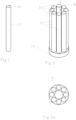
figure 1 shows an isometric view of an ionisation chamber according to the present invention; -
figures 2 and 2a show, respectively, an isometric view and a top view of a first embodiment of a radiation detector according to the present invention; -
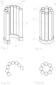
figures 3 and 3a show, respectively, an isometric view and a top view of a second embodiment of a radiation detector according to the present invention, in an open configuration; -
figures 4 and 4a show, respectively, an isometric view and a top view of the detector infigure 3 , in a closed configuration; -
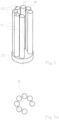
figures 5 and 5a show, respectively, an isometric view and a top view of a third embodiment of a radiation detector according to the present invention; -
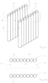
figures 6 and 6a show, respectively, an isometric view and a top view of a fourth embodiment of a radiation detector according to the present invention. - The radiation detector according to the present invention lends itself particularly well to use in a fractionation apparatus, configured for the preparation of pre-determined doses of a radiopharmaceutical.
- The detector may be located inside a shielded booth together with other known accessories, including a support for a syringe, a support for a bulk container of the radiopharmaceutical, a feed circuit for feeding the radiopharmaceutical and saline solution or other substances, and electronics for controlling and managing the various devices.
- The radiation detector according to the present invention comprises two or more ionisation chambers (10), each of which comprises a main body (11), intended to contain a measuring gas which, as is well known, ionises following exposure to radiation. A gas widely used to detect radiation is argon. The entity of ionisation that the gas undergoes, measurable by means of electronic circuits known in the art, depends on the intensity of the radiation it is exposed to. Ionisation chambers (10) are configured to detect alpha, beta or gamma sources.
- Advantageously, the main bodies (11) are arranged in such a way as to delimit a measurement space (M) inside which a radiation source may be positioned. Essentially, instead of using a single ionisation chamber with a cylindrical shape, as is the case with current detectors, the present invention envisages the use of two or more ionisation chambers (10), arranged in such a way as to delimit a measurement space (M), whose shape and size can be selected based on the shape and size of the sources to be measured. Moreover, the ionisation chambers (10) can be mounted on movable supports so as to enable a change in the shape of the measurement space (M), or enable an opening of the measurement space (M) and facilitate the introduction of the source to be measured along a substantially horizontal direction of access. In other words, the source, i.e. the syringe containing the radiopharmaceutical, can be introduced into the measurement space (M) not from above, as is presently the case, but from the front, i.e. along a substantially horizontal direction of access. In general, and above all in the case of a fractionation apparatus, this enables a considerable reduction in the size of the booth intended to contain the detector. In fact, the booth can be dimensioned so as to contain the detector with modest margins height-wise, since the source to be detected has to be introduced into the measurement space (M) not from above, but horizontally.
- A further advantage tied to the use of more than one ionisation chamber (10), rather than only one, is that each of them will have a relatively compact size, thus enabling them to withstand higher internal pressures with smaller wall thicknesses compared to the prior art. This results in a considerable increase in detection efficiency.
- For example, the ionisation chambers (10) can be arranged so as to surround a measurement space (M) that is cylindrical or prismatic overall, endowed with a longitudinal axis (Y). The longitudinal axis (Y) is preferably vertically oriented. Examples of such an arrangement are shown in
figures 2 ,4 and5 . - In a possible embodiment, the ionisation chambers (10) can be arranged in such a way that the main bodies (11) are distributed along a closed curve (C) lying in a plane which is perpendicular to the longitudinal axis (Y). In other words, the ionisation chambers (10) can be arranged in such a way as to surround a cylindrical space with a circular, oval or polygonal cross section, in relation to the shape of the source to be measured, and having a vertically oriented longitudinal axis (Y). In this case, the overall geometry of the measurement space (M) is of the well type, as in the current devices, but the use of more than one ionisation chamber (10) allows the shape of the measurement space (M) to be varied in a way that would be otherwise impossible using a single ionisation chamber.
- In a further embodiment, schematically illustrated in
figures 3 and 4 , the detector according to the present invention comprises a plurality of ionisation chambers (10a,10b). A part of the ionisation chambers (10a) is movable relative to the remaining part of the ionisation chambers (10b) between a measurement position, in which the main bodies (11) are distributed along a closed curve (C), and a service position, in which the main bodies (11) are distributed along a line or an open curve (A). As previously noted, the closed curve (C) can be of any shape and the overall geometry of the measurement space (M) is cylindrical. Thanks to the use of more than one ionisation chamber (10a,10b), distributed as described, the measurement space (M) can be open so as to enable the introduction of the source along a horizontal direction, that is, not necessarily from above along the longitudinal direction of the measurement space (M), as is the case with current detectors. This means that the detector requires much less room for manoeuvre around it than is required by current detectors, which require the introduction of the source from above and thus all the space necessary for the introduction from above of the detector. - In a further possible embodiment, the ionisation chambers (10) can be arranged in such a way that the main bodies (11) are distributed along an open curve (R). In such a case the overall geometry of the measurement space (M) is again cylindrical, or well-type, but open at the side to facilitate the introduction of the source to be measured along a horizontal direction. The open curve (R) can be, for example, a circumferential arc which is concentric to the longitudinal axis (Y).
- In a further possible embodiment, shown in
figures 6 and 6a , the ionisation chambers (10) can be arranged in such a way that the main bodies (11) are distributed along two rows (I, II) parallel to an alignment direction (X). In such a case, the measurement space (M) has a prismatic geometry, and can be open at both ends (a,b) of the two rows (I, II) of ionisation chambers (10), or else at one end only. The source to be measured can be introduced into the measurement space (M) along a direction which is parallel to the alignment direction (X) of the ionisation chambers (10). If the measurement space (M) is open at both ends, the source can be introduced and extracted rectilinearly along the alignment direction (X) in one way only, that is, the source can be introduced through a first end of the measurement space (M) and be extracted from the opposite end. If the measurement space (M) is closed at one end, introduction and extraction must obviously take place through the open end. - According to the invention, the main bodies (11) have a cylindrical conformation. This conformation offers high resistance to internal pressure, so the gas can be contained at high pressures, even 15 bar, without requiring large wall thicknesses, thus considerably improving detection efficiency. Furthermore, the longitudinal dimension, i.e. the length of the main bodies (11), can be considerably increased, enabling a further increase in detection efficiency.
- The ionisation chambers (10) can be arranged with the main cylindrical bodies (11) oriented vertically, i.e. parallel to the longitudinal axis (Y) of the measurement space (M). The closed curve (C), open curve (A) and parallel rows (I, II) described previously are to be understood as lying in a plane which is perpendicular to the longitudinal axis (Y) of the measurement space (M).
- In a possible embodiment, the main bodies (11) are independent from each other, i.e. each main body (11) is closed and delimits a containment volume for the gas used to detect radiation.
- In an alternative embodiment, the main bodies (11) are connected to a manifold (15). In other words, the main bodies (11) and the manifold (15) delimit a closed volume for containing the measuring gas. The manifold (15) comprises a conduit for containing the measuring gas. For example, the manifold (15) can be ring-shaped, and the main bodies (11) can be connected to the manifold (15) projecting parallel to each other. The manifold (15) could also have a rectilinear shape or any other shape.
- An electronic circuit, known in the art and thus not described in detail, can be connected to the ionisation chambers (10) in order to detect the overall ionisation of the gas and translate the detected ionisation into a radiation measurement. The circuit is commonly called an "electrometer". It enables, with different circuitries, the ionisation current produced by the incident radiation in the gas to be efficiently collected.
- The electronic circuit is configured to add together the contributions of all of the ionisation chambers (10) in order to obtain a measurement of the total radiation. In other words, the electronic circuit is configured to integrate the ionisation current that is produced in the different ionisation chambers (10) in order to obtain a single electric signal.
- For this purpose, each ionisation chamber (10) comprises an anode and a cathode, maintained at a potential difference by the electrometer itself and generally comprised between 150 and 500 Volts. The ions produced in the gas by the radioactive particles collect at the anode or cathode depending on their charge, thus producing a current. The ionisation currents produced in the various ionisation chambers (10) are integrated together in order to obtain a single electrical signal. The current is amplified by a circuit present in the electrometer, so as to generate a signal which is proportional to the ionisation current. The signal is then processed in order to be sent to a control and management module of the instrument (with a user interface). Finally, a calibration procedure, through the use of radioactive sources with known activity, enables the amplified and processed signal to be converted into units of radioactivity.
Claims (9)
- A fractionation apparatus for preparing doses of radiopharmaceuticals, comprising: a support for a syringe or another container intended to receive a predetermined dose of a radiopharmaceutical; a support for a bulk container of a radiopharmaceutical; an hydraulic circuit, configured to connect the container of the radiopharmaceutical and a saline solution source to the syringe;a radiation detector, comprising two or more ionisation chambers (10), each of which comprises a main body (11), and which are arranged in such a way that the main bodies (11) delimit a measurement space (M) inside which a radiation source may be positioned;an electronic circuit, configured to detect the total ionisation of the measuring gas contained in the ionisation chambers (10);wherein the support for a syringe or another container is located inside the measurement space (M) of radiation detector;characterised in that each main body (11) has a cylindrical conformation.
- The fractionation apparatus according to claim 1, wherein the electronic circuit is configured to integrate the ionisation currents that are produced in the various ionisation chambers (10) in order to obtain a single electrical signal.
- The fractionation apparatus according to claim 1, comprising a plurality of ionisation chambers (10) arranged in such a way that the main bodies (11) are distributed along a closed curve (C).
- The fractionation apparatus according to claim 1, comprising a plurality of ionisation chambers (10), wherein a part of the ionisation chambers (10a) is movable relative to the remaining part of the ionisation chambers (10b) between a measurement position, in which the main bodies (11) are distributed along a closed curve (C), and a service position, in which the main bodies (11) are distributed along a line or an open curve (A).
- The fractionation apparatus according to claim 1, comprising a plurality of ionisation chambers (10) arranged in such a way that the main bodies (11) are distributed along an open curve (R).
- The fractionation apparatus according to claim 1, comprising a plurality of ionisation chambers (10) arranged in such a way that the main bodies are distributed along two parallel rows (I, II).
- The fractionation apparatus according to claim 1, wherein each main body (11) is closed and delimits a containment volume for a gas.
- The fractionation apparatus according to claim 1, wherein the main bodies (11) are connected to a manifold (15); the main bodies (11) and the manifold (15) delimit a closed volume for the containment of a gas.
- A machine for preparing doses of radiopharmaceuticals, comprising a containment booth, provided with radiation shields, located inside which there is a fractionation apparatus according to one of the preceding claims.
Applications Claiming Priority (2)
| Application Number | Priority Date | Filing Date | Title |
|---|---|---|---|
| IT201700146433 | 2017-12-19 | ||
| PCT/IB2018/060322 WO2019123304A1 (en) | 2017-12-19 | 2018-12-19 | A radiation detector |
Publications (2)
| Publication Number | Publication Date |
|---|---|
| EP3729142A1 EP3729142A1 (en) | 2020-10-28 |
| EP3729142B1 true EP3729142B1 (en) | 2023-08-30 |
Family
ID=61802251
Family Applications (1)
| Application Number | Title | Priority Date | Filing Date |
|---|---|---|---|
| EP18833116.9A Active EP3729142B1 (en) | 2017-12-19 | 2018-12-19 | A radiation detector |
Country Status (5)
| Country | Link |
|---|---|
| US (1) | US11953630B2 (en) |
| EP (1) | EP3729142B1 (en) |
| CA (1) | CA3085818A1 (en) |
| ES (1) | ES2958069T3 (en) |
| WO (1) | WO2019123304A1 (en) |
Citations (1)
| Publication number | Priority date | Publication date | Assignee | Title |
|---|---|---|---|---|
| FR2251911A1 (en) * | 1973-11-15 | 1975-06-13 | Commissariat Energie Atomique | Air ionisation chamber - for measuring radioactivity of a sample, partic. a physiological serum contg. technetium-99m |
Family Cites Families (11)
| Publication number | Priority date | Publication date | Assignee | Title |
|---|---|---|---|---|
| FR1183892A (en) | 1956-10-05 | 1959-07-15 | Philips Nv | Radiation detector |
| US4483816A (en) * | 1982-03-31 | 1984-11-20 | The United States Of America As Represented By The Department Of Energy | Apparatus and method for quantitative assay of generic transuranic wastes from nuclear reactors |
| US4617466A (en) * | 1985-02-04 | 1986-10-14 | The United States Of America As Represented By The United States Department Of Energy | Direct fissile assay of enriched uranium using random self-interrogation and neutron coincidence response |
| US5095217A (en) * | 1990-10-17 | 1992-03-10 | Wisconsin Alumni Research Foundation | Well-type ionization chamber radiation detector for calibration of radioactive sources |
| US20020163987A1 (en) | 1997-12-12 | 2002-11-07 | British Nuclear Fuels Plc | Monitoring a sample containing a neutron source |
| US9627097B2 (en) * | 2004-03-02 | 2017-04-18 | General Electric Company | Systems, methods and apparatus for infusion of radiopharmaceuticals |
| US7615740B2 (en) * | 2006-04-11 | 2009-11-10 | Radqual, Llc | Syringe-shaped dose calibration source standard |
| US9326742B2 (en) * | 2007-01-01 | 2016-05-03 | Bayer Healthcare Llc | Systems for integrated radiopharmaceutical generation, preparation, transportation and administration |
| GB0817703D0 (en) * | 2008-09-26 | 2008-11-05 | Vt Nuclear Services Ltd | Improvements in and relating to assaying of waste |
| US9632188B2 (en) | 2011-08-02 | 2017-04-25 | Raytheon Company | Noble gas detector for fissile content determination |
| US9176088B2 (en) * | 2011-12-14 | 2015-11-03 | Microchip Technology Incorporated | Method and apparatus for detecting smoke in an ion chamber |
-
2018
- 2018-12-19 WO PCT/IB2018/060322 patent/WO2019123304A1/en unknown
- 2018-12-19 ES ES18833116T patent/ES2958069T3/en active Active
- 2018-12-19 EP EP18833116.9A patent/EP3729142B1/en active Active
- 2018-12-19 US US16/954,764 patent/US11953630B2/en active Active
- 2018-12-19 CA CA3085818A patent/CA3085818A1/en active Granted
Patent Citations (1)
| Publication number | Priority date | Publication date | Assignee | Title |
|---|---|---|---|---|
| FR2251911A1 (en) * | 1973-11-15 | 1975-06-13 | Commissariat Energie Atomique | Air ionisation chamber - for measuring radioactivity of a sample, partic. a physiological serum contg. technetium-99m |
Also Published As
| Publication number | Publication date |
|---|---|
| ES2958069T3 (en) | 2024-01-31 |
| US20210088676A1 (en) | 2021-03-25 |
| EP3729142A1 (en) | 2020-10-28 |
| US11953630B2 (en) | 2024-04-09 |
| WO2019123304A1 (en) | 2019-06-27 |
| CA3085818A1 (en) | 2019-06-27 |
Similar Documents
| Publication | Publication Date | Title |
|---|---|---|
| RU2599866C2 (en) | System and method of measuring concentration of radiopharmaceutical agents | |
| US7608831B2 (en) | Radioactivity dose calibrator | |
| Johnston et al. | Proton-proton scattering at 40 MeV | |
| US8872124B2 (en) | Systems and methods for assaying an eluate for technetium and molybdenum content | |
| Poleshchuk et al. | The SpecMAT active target | |
| EP3729142B1 (en) | A radiation detector | |
| CA3085818C (en) | A radiation detector | |
| Brockmeier et al. | Observation of the Isotope Shift of K α 1 X Rays of Uranium | |
| CN201130252Y (en) | Combined gamma counter | |
| US4631410A (en) | Method and apparatus for measurement of radioactivity over an extended range | |
| Yavar et al. | Neutron flux parameters for k0-NAA method at the Malaysian nuclear agency research reactor after core reconfiguration | |
| JP2014202510A (en) | Radiation measuring device | |
| US3621238A (en) | Gamma insensitive air monitor for radioactive gases | |
| Bogdzel et al. | Thermal Neutron Detectors for IBR-2 Spectrometers | |
| Lalovic et al. | The energy distribution of antimonyberyllium photoneutrons | |
| Al-Anezi et al. | Non-imaging and Radiopharmacy Instrumentation in Nuclear Medicine | |
| US11391853B2 (en) | System and method for evaluating elution efficiency and radiopurity of tc-99m generators | |
| US2961543A (en) | Monitoring apparatus for radioactive effluents from nuclear reactors | |
| KR100928772B1 (en) | Gamma-ray spectroscopy apparatus for collimators and spent fuel containing the same | |
| CN114488254A (en) | Detection device and detection system for ray emissivity measurement | |
| KR101657665B1 (en) | radiation detector | |
| RU2482513C2 (en) | Method of processing fission chamber measurement signals | |
| Zimmer et al. | Assay of 32P-SodiumPhosphate Using a Commercial Dose Calibrator | |
| Fsel'son et al. | Attachment to spextrophotometers for measuring scattering patterns | |
| CN113866819A (en) | Device and method for calibrating transuranic nuclide aerosol on-line monitoring equipment |
Legal Events
| Date | Code | Title | Description |
|---|---|---|---|
| STAA | Information on the status of an ep patent application or granted ep patent |
Free format text: STATUS: UNKNOWN |
|
| STAA | Information on the status of an ep patent application or granted ep patent |
Free format text: STATUS: THE INTERNATIONAL PUBLICATION HAS BEEN MADE |
|
| PUAI | Public reference made under article 153(3) epc to a published international application that has entered the european phase |
Free format text: ORIGINAL CODE: 0009012 |
|
| STAA | Information on the status of an ep patent application or granted ep patent |
Free format text: STATUS: REQUEST FOR EXAMINATION WAS MADE |
|
| 17P | Request for examination filed |
Effective date: 20200616 |
|
| AK | Designated contracting states |
Kind code of ref document: A1 Designated state(s): AL AT BE BG CH CY CZ DE DK EE ES FI FR GB GR HR HU IE IS IT LI LT LU LV MC MK MT NL NO PL PT RO RS SE SI SK SM TR |
|
| AX | Request for extension of the european patent |
Extension state: BA ME |
|
| RIN1 | Information on inventor provided before grant (corrected) |
Inventor name: MORETTI, ELENA Inventor name: SABBA, NICOLA |
|
| DAV | Request for validation of the european patent (deleted) | ||
| DAX | Request for extension of the european patent (deleted) | ||
| STAA | Information on the status of an ep patent application or granted ep patent |
Free format text: STATUS: EXAMINATION IS IN PROGRESS |
|
| 17Q | First examination report despatched |
Effective date: 20221109 |
|
| GRAP | Despatch of communication of intention to grant a patent |
Free format text: ORIGINAL CODE: EPIDOSNIGR1 |
|
| STAA | Information on the status of an ep patent application or granted ep patent |
Free format text: STATUS: GRANT OF PATENT IS INTENDED |
|
| INTG | Intention to grant announced |
Effective date: 20230426 |
|
| GRAS | Grant fee paid |
Free format text: ORIGINAL CODE: EPIDOSNIGR3 |
|
| GRAA | (expected) grant |
Free format text: ORIGINAL CODE: 0009210 |
|
| STAA | Information on the status of an ep patent application or granted ep patent |
Free format text: STATUS: THE PATENT HAS BEEN GRANTED |
|
| AK | Designated contracting states |
Kind code of ref document: B1 Designated state(s): AL AT BE BG CH CY CZ DE DK EE ES FI FR GB GR HR HU IE IS IT LI LT LU LV MC MK MT NL NO PL PT RO RS SE SI SK SM TR |
|
| P01 | Opt-out of the competence of the unified patent court (upc) registered |
Effective date: 20230724 |
|
| REG | Reference to a national code |
Ref country code: GB Ref legal event code: FG4D |
|
| REG | Reference to a national code |
Ref country code: CH Ref legal event code: EP |
|
| REG | Reference to a national code |
Ref country code: DE Ref legal event code: R096 Ref document number: 602018056607 Country of ref document: DE |
|
| REG | Reference to a national code |
Ref country code: IE Ref legal event code: FG4D |
|
| REG | Reference to a national code |
Ref country code: NL Ref legal event code: FP |
|
| REG | Reference to a national code |
Ref country code: LT Ref legal event code: MG9D |
|
| PG25 | Lapsed in a contracting state [announced via postgrant information from national office to epo] |
Ref country code: GR Free format text: LAPSE BECAUSE OF FAILURE TO SUBMIT A TRANSLATION OF THE DESCRIPTION OR TO PAY THE FEE WITHIN THE PRESCRIBED TIME-LIMIT Effective date: 20231201 |
|
| PG25 | Lapsed in a contracting state [announced via postgrant information from national office to epo] |
Ref country code: IS Free format text: LAPSE BECAUSE OF FAILURE TO SUBMIT A TRANSLATION OF THE DESCRIPTION OR TO PAY THE FEE WITHIN THE PRESCRIBED TIME-LIMIT Effective date: 20231230 |
|
| PG25 | Lapsed in a contracting state [announced via postgrant information from national office to epo] |
Ref country code: SE Free format text: LAPSE BECAUSE OF FAILURE TO SUBMIT A TRANSLATION OF THE DESCRIPTION OR TO PAY THE FEE WITHIN THE PRESCRIBED TIME-LIMIT Effective date: 20230830 Ref country code: RS Free format text: LAPSE BECAUSE OF FAILURE TO SUBMIT A TRANSLATION OF THE DESCRIPTION OR TO PAY THE FEE WITHIN THE PRESCRIBED TIME-LIMIT Effective date: 20230830 Ref country code: NO Free format text: LAPSE BECAUSE OF FAILURE TO SUBMIT A TRANSLATION OF THE DESCRIPTION OR TO PAY THE FEE WITHIN THE PRESCRIBED TIME-LIMIT Effective date: 20231130 Ref country code: LV Free format text: LAPSE BECAUSE OF FAILURE TO SUBMIT A TRANSLATION OF THE DESCRIPTION OR TO PAY THE FEE WITHIN THE PRESCRIBED TIME-LIMIT Effective date: 20230830 Ref country code: LT Free format text: LAPSE BECAUSE OF FAILURE TO SUBMIT A TRANSLATION OF THE DESCRIPTION OR TO PAY THE FEE WITHIN THE PRESCRIBED TIME-LIMIT Effective date: 20230830 Ref country code: IS Free format text: LAPSE BECAUSE OF FAILURE TO SUBMIT A TRANSLATION OF THE DESCRIPTION OR TO PAY THE FEE WITHIN THE PRESCRIBED TIME-LIMIT Effective date: 20231230 Ref country code: HR Free format text: LAPSE BECAUSE OF FAILURE TO SUBMIT A TRANSLATION OF THE DESCRIPTION OR TO PAY THE FEE WITHIN THE PRESCRIBED TIME-LIMIT Effective date: 20230830 Ref country code: GR Free format text: LAPSE BECAUSE OF FAILURE TO SUBMIT A TRANSLATION OF THE DESCRIPTION OR TO PAY THE FEE WITHIN THE PRESCRIBED TIME-LIMIT Effective date: 20231201 Ref country code: FI Free format text: LAPSE BECAUSE OF FAILURE TO SUBMIT A TRANSLATION OF THE DESCRIPTION OR TO PAY THE FEE WITHIN THE PRESCRIBED TIME-LIMIT Effective date: 20230830 |
|
| PGFP | Annual fee paid to national office [announced via postgrant information from national office to epo] |
Ref country code: NL Payment date: 20231226 Year of fee payment: 6 Ref country code: IT Payment date: 20231227 Year of fee payment: 6 Ref country code: FR Payment date: 20231226 Year of fee payment: 6 Ref country code: AT Payment date: 20231229 Year of fee payment: 6 |
|
| REG | Reference to a national code |
Ref country code: ES Ref legal event code: FG2A Ref document number: 2958069 Country of ref document: ES Kind code of ref document: T3 Effective date: 20240131 |
|
| REG | Reference to a national code |
Ref country code: AT Ref legal event code: UEP Ref document number: 1606144 Country of ref document: AT Kind code of ref document: T Effective date: 20230830 |
|
| PG25 | Lapsed in a contracting state [announced via postgrant information from national office to epo] |
Ref country code: PL Free format text: LAPSE BECAUSE OF FAILURE TO SUBMIT A TRANSLATION OF THE DESCRIPTION OR TO PAY THE FEE WITHIN THE PRESCRIBED TIME-LIMIT Effective date: 20230830 |
|
| PGFP | Annual fee paid to national office [announced via postgrant information from national office to epo] |
Ref country code: BE Payment date: 20231226 Year of fee payment: 6 |
|
| PGFP | Annual fee paid to national office [announced via postgrant information from national office to epo] |
Ref country code: ES Payment date: 20240119 Year of fee payment: 6 |
|
| PG25 | Lapsed in a contracting state [announced via postgrant information from national office to epo] |
Ref country code: SM Free format text: LAPSE BECAUSE OF FAILURE TO SUBMIT A TRANSLATION OF THE DESCRIPTION OR TO PAY THE FEE WITHIN THE PRESCRIBED TIME-LIMIT Effective date: 20230830 Ref country code: RO Free format text: LAPSE BECAUSE OF FAILURE TO SUBMIT A TRANSLATION OF THE DESCRIPTION OR TO PAY THE FEE WITHIN THE PRESCRIBED TIME-LIMIT Effective date: 20230830 Ref country code: EE Free format text: LAPSE BECAUSE OF FAILURE TO SUBMIT A TRANSLATION OF THE DESCRIPTION OR TO PAY THE FEE WITHIN THE PRESCRIBED TIME-LIMIT Effective date: 20230830 Ref country code: DK Free format text: LAPSE BECAUSE OF FAILURE TO SUBMIT A TRANSLATION OF THE DESCRIPTION OR TO PAY THE FEE WITHIN THE PRESCRIBED TIME-LIMIT Effective date: 20230830 Ref country code: CZ Free format text: LAPSE BECAUSE OF FAILURE TO SUBMIT A TRANSLATION OF THE DESCRIPTION OR TO PAY THE FEE WITHIN THE PRESCRIBED TIME-LIMIT Effective date: 20230830 Ref country code: PT Free format text: LAPSE BECAUSE OF FAILURE TO SUBMIT A TRANSLATION OF THE DESCRIPTION OR TO PAY THE FEE WITHIN THE PRESCRIBED TIME-LIMIT Effective date: 20240102 Ref country code: SK Free format text: LAPSE BECAUSE OF FAILURE TO SUBMIT A TRANSLATION OF THE DESCRIPTION OR TO PAY THE FEE WITHIN THE PRESCRIBED TIME-LIMIT Effective date: 20230830 |
|
| PGFP | Annual fee paid to national office [announced via postgrant information from national office to epo] |
Ref country code: DE Payment date: 20231227 Year of fee payment: 6 |