EP3722993A1 - System for performing eye detection and/or tracking - Google Patents
System for performing eye detection and/or tracking Download PDFInfo
- Publication number
- EP3722993A1 EP3722993A1 EP20162552.2A EP20162552A EP3722993A1 EP 3722993 A1 EP3722993 A1 EP 3722993A1 EP 20162552 A EP20162552 A EP 20162552A EP 3722993 A1 EP3722993 A1 EP 3722993A1
- Authority
- EP
- European Patent Office
- Prior art keywords
- user
- image data
- imaging device
- face
- determining
- Prior art date
- Legal status (The legal status is an assumption and is not a legal conclusion. Google has not performed a legal analysis and makes no representation as to the accuracy of the status listed.)
- Ceased
Links
- 238000001514 detection method Methods 0.000 title claims description 14
- 238000003384 imaging method Methods 0.000 claims abstract description 228
- 238000000034 method Methods 0.000 claims abstract description 50
- 210000001747 pupil Anatomy 0.000 claims description 16
- 230000008859 change Effects 0.000 claims description 10
- 238000005286 illumination Methods 0.000 claims description 10
- 230000004044 response Effects 0.000 claims description 5
- 230000006978 adaptation Effects 0.000 claims description 4
- 230000001815 facial effect Effects 0.000 claims description 2
- 230000007774 longterm Effects 0.000 claims description 2
- 230000015654 memory Effects 0.000 description 16
- 230000008569 process Effects 0.000 description 16
- 238000004458 analytical method Methods 0.000 description 11
- 238000013528 artificial neural network Methods 0.000 description 7
- 238000010586 diagram Methods 0.000 description 5
- 238000012545 processing Methods 0.000 description 5
- 230000006870 function Effects 0.000 description 4
- 238000003491 array Methods 0.000 description 2
- 230000001276 controlling effect Effects 0.000 description 2
- 238000013527 convolutional neural network Methods 0.000 description 2
- 238000005516 engineering process Methods 0.000 description 2
- 238000010801 machine learning Methods 0.000 description 2
- 238000012986 modification Methods 0.000 description 2
- 230000004048 modification Effects 0.000 description 2
- 230000003287 optical effect Effects 0.000 description 2
- 208000020564 Eye injury Diseases 0.000 description 1
- 230000003044 adaptive effect Effects 0.000 description 1
- 230000009286 beneficial effect Effects 0.000 description 1
- 230000004321 blink reflex Effects 0.000 description 1
- 238000004891 communication Methods 0.000 description 1
- 230000002596 correlated effect Effects 0.000 description 1
- 238000013135 deep learning Methods 0.000 description 1
- 238000009499 grossing Methods 0.000 description 1
- 238000010191 image analysis Methods 0.000 description 1
- 238000012880 independent component analysis Methods 0.000 description 1
- 230000006698 induction Effects 0.000 description 1
- 230000035987 intoxication Effects 0.000 description 1
- 231100000566 intoxication Toxicity 0.000 description 1
- 238000012417 linear regression Methods 0.000 description 1
- 238000007477 logistic regression Methods 0.000 description 1
- 238000012544 monitoring process Methods 0.000 description 1
- 238000013488 ordinary least square regression Methods 0.000 description 1
- 238000000513 principal component analysis Methods 0.000 description 1
- 230000035484 reaction time Effects 0.000 description 1
- 238000001228 spectrum Methods 0.000 description 1
- 230000001360 synchronised effect Effects 0.000 description 1
- 238000012360 testing method Methods 0.000 description 1
Images


Classifications
-
- G—PHYSICS
- G06—COMPUTING; CALCULATING OR COUNTING
- G06T—IMAGE DATA PROCESSING OR GENERATION, IN GENERAL
- G06T7/00—Image analysis
- G06T7/20—Analysis of motion
- G06T7/246—Analysis of motion using feature-based methods, e.g. the tracking of corners or segments
-
- G—PHYSICS
- G06—COMPUTING; CALCULATING OR COUNTING
- G06V—IMAGE OR VIDEO RECOGNITION OR UNDERSTANDING
- G06V40/00—Recognition of biometric, human-related or animal-related patterns in image or video data
- G06V40/10—Human or animal bodies, e.g. vehicle occupants or pedestrians; Body parts, e.g. hands
- G06V40/16—Human faces, e.g. facial parts, sketches or expressions
- G06V40/161—Detection; Localisation; Normalisation
- G06V40/167—Detection; Localisation; Normalisation using comparisons between temporally consecutive images
-
- B—PERFORMING OPERATIONS; TRANSPORTING
- B60—VEHICLES IN GENERAL
- B60Q—ARRANGEMENT OF SIGNALLING OR LIGHTING DEVICES, THE MOUNTING OR SUPPORTING THEREOF OR CIRCUITS THEREFOR, FOR VEHICLES IN GENERAL
- B60Q3/00—Arrangement of lighting devices for vehicle interiors; Lighting devices specially adapted for vehicle interiors
- B60Q3/10—Arrangement of lighting devices for vehicle interiors; Lighting devices specially adapted for vehicle interiors for dashboards
- B60Q3/16—Circuits; Control arrangements
- B60Q3/18—Circuits; Control arrangements for varying the light intensity
-
- B—PERFORMING OPERATIONS; TRANSPORTING
- B60—VEHICLES IN GENERAL
- B60R—VEHICLES, VEHICLE FITTINGS, OR VEHICLE PARTS, NOT OTHERWISE PROVIDED FOR
- B60R11/00—Arrangements for holding or mounting articles, not otherwise provided for
- B60R11/04—Mounting of cameras operative during drive; Arrangement of controls thereof relative to the vehicle
-
- B—PERFORMING OPERATIONS; TRANSPORTING
- B60—VEHICLES IN GENERAL
- B60W—CONJOINT CONTROL OF VEHICLE SUB-UNITS OF DIFFERENT TYPE OR DIFFERENT FUNCTION; CONTROL SYSTEMS SPECIALLY ADAPTED FOR HYBRID VEHICLES; ROAD VEHICLE DRIVE CONTROL SYSTEMS FOR PURPOSES NOT RELATED TO THE CONTROL OF A PARTICULAR SUB-UNIT
- B60W40/00—Estimation or calculation of non-directly measurable driving parameters for road vehicle drive control systems not related to the control of a particular sub unit, e.g. by using mathematical models
- B60W40/08—Estimation or calculation of non-directly measurable driving parameters for road vehicle drive control systems not related to the control of a particular sub unit, e.g. by using mathematical models related to drivers or passengers
- B60W40/09—Driving style or behaviour
-
- G—PHYSICS
- G06—COMPUTING; CALCULATING OR COUNTING
- G06F—ELECTRIC DIGITAL DATA PROCESSING
- G06F3/00—Input arrangements for transferring data to be processed into a form capable of being handled by the computer; Output arrangements for transferring data from processing unit to output unit, e.g. interface arrangements
- G06F3/01—Input arrangements or combined input and output arrangements for interaction between user and computer
- G06F3/011—Arrangements for interaction with the human body, e.g. for user immersion in virtual reality
- G06F3/013—Eye tracking input arrangements
-
- G—PHYSICS
- G06—COMPUTING; CALCULATING OR COUNTING
- G06T—IMAGE DATA PROCESSING OR GENERATION, IN GENERAL
- G06T7/00—Image analysis
- G06T7/70—Determining position or orientation of objects or cameras
- G06T7/73—Determining position or orientation of objects or cameras using feature-based methods
- G06T7/74—Determining position or orientation of objects or cameras using feature-based methods involving reference images or patches
-
- G—PHYSICS
- G06—COMPUTING; CALCULATING OR COUNTING
- G06V—IMAGE OR VIDEO RECOGNITION OR UNDERSTANDING
- G06V10/00—Arrangements for image or video recognition or understanding
- G06V10/10—Image acquisition
- G06V10/12—Details of acquisition arrangements; Constructional details thereof
- G06V10/14—Optical characteristics of the device performing the acquisition or on the illumination arrangements
- G06V10/143—Sensing or illuminating at different wavelengths
-
- G—PHYSICS
- G06—COMPUTING; CALCULATING OR COUNTING
- G06V—IMAGE OR VIDEO RECOGNITION OR UNDERSTANDING
- G06V20/00—Scenes; Scene-specific elements
- G06V20/50—Context or environment of the image
- G06V20/59—Context or environment of the image inside of a vehicle, e.g. relating to seat occupancy, driver state or inner lighting conditions
- G06V20/597—Recognising the driver's state or behaviour, e.g. attention or drowsiness
-
- G—PHYSICS
- G06—COMPUTING; CALCULATING OR COUNTING
- G06V—IMAGE OR VIDEO RECOGNITION OR UNDERSTANDING
- G06V40/00—Recognition of biometric, human-related or animal-related patterns in image or video data
- G06V40/10—Human or animal bodies, e.g. vehicle occupants or pedestrians; Body parts, e.g. hands
- G06V40/18—Eye characteristics, e.g. of the iris
- G06V40/19—Sensors therefor
-
- B—PERFORMING OPERATIONS; TRANSPORTING
- B60—VEHICLES IN GENERAL
- B60R—VEHICLES, VEHICLE FITTINGS, OR VEHICLE PARTS, NOT OTHERWISE PROVIDED FOR
- B60R11/00—Arrangements for holding or mounting articles, not otherwise provided for
- B60R2011/0042—Arrangements for holding or mounting articles, not otherwise provided for characterised by mounting means
- B60R2011/008—Adjustable or movable supports
- B60R2011/0085—Adjustable or movable supports with adjustment by rotation in their operational position
-
- B—PERFORMING OPERATIONS; TRANSPORTING
- B60—VEHICLES IN GENERAL
- B60W—CONJOINT CONTROL OF VEHICLE SUB-UNITS OF DIFFERENT TYPE OR DIFFERENT FUNCTION; CONTROL SYSTEMS SPECIALLY ADAPTED FOR HYBRID VEHICLES; ROAD VEHICLE DRIVE CONTROL SYSTEMS FOR PURPOSES NOT RELATED TO THE CONTROL OF A PARTICULAR SUB-UNIT
- B60W40/00—Estimation or calculation of non-directly measurable driving parameters for road vehicle drive control systems not related to the control of a particular sub unit, e.g. by using mathematical models
- B60W40/08—Estimation or calculation of non-directly measurable driving parameters for road vehicle drive control systems not related to the control of a particular sub unit, e.g. by using mathematical models related to drivers or passengers
- B60W2040/0818—Inactivity or incapacity of driver
-
- B—PERFORMING OPERATIONS; TRANSPORTING
- B60—VEHICLES IN GENERAL
- B60W—CONJOINT CONTROL OF VEHICLE SUB-UNITS OF DIFFERENT TYPE OR DIFFERENT FUNCTION; CONTROL SYSTEMS SPECIALLY ADAPTED FOR HYBRID VEHICLES; ROAD VEHICLE DRIVE CONTROL SYSTEMS FOR PURPOSES NOT RELATED TO THE CONTROL OF A PARTICULAR SUB-UNIT
- B60W2540/00—Input parameters relating to occupants
- B60W2540/229—Attention level, e.g. attentive to driving, reading or sleeping
-
- G—PHYSICS
- G06—COMPUTING; CALCULATING OR COUNTING
- G06T—IMAGE DATA PROCESSING OR GENERATION, IN GENERAL
- G06T2207/00—Indexing scheme for image analysis or image enhancement
- G06T2207/30—Subject of image; Context of image processing
- G06T2207/30196—Human being; Person
- G06T2207/30201—Face
Definitions
- the present invention relates to a system for performing eye detection and/or tracking.
- a system may use a camera installed in a vehicle to capture images of users located within the vehicle. The system may then analyze the images to determine at least the gaze direction of the user driving the vehicle. A vehicle control system may then use the gaze direction to determine if the user is paying attention to the road while driving the vehicle. If the user is not paying attention to the road, the vehicle control system may output a sound or other alert to the user.
- these systems have problems performing eye tracking to determine the gaze direction or other eye related attributes of the user.
- the camera may require a wide-angle lens to capture images that represent the environment.
- only a small portion of the images may represent the eyes of the user, which can cause problems for the system analyzing the images using eye tracking.
- the system may be unable to identify the eyes of the user using the images.
- some systems use high-resolution cameras to capture the images.
- using high-resolution cameras may increase processing load, which may increase latency, power consumption, and/or heat generated by the system.
- the method further comprises determining the second position for the actuator based at least in part on the portion of the first image data.
- the method comprises: generating the first image data comprises generating, using the first imaging device, the first image data using a first frame rate and a first resolution; generating the second image data comprises generating, using the second imaging device, the second image data using a second frame rate and a second resolution; and at least one of the first frame rate is different than the second frame rate, or the first resolution is different than the second resolution.
- the method comprises determining the second position for the actuator based at least in part on the location of the face of the user and a position of the second imaging device relative to a position of the first imaging device.
- the method further comprises emitting, using a light source associated with the second imaging device, light towards the face of the user.
- the first image data further represents a first field of view, FOV, of the first imaging device; the second image data further represents a second FOV of the second imaging device; and the second FOV is smaller than the first FOV.
- FOV field of view
- a system comprising: a first imaging device; a second imaging device; an actuator for positioning the second imaging device; one or more processors; and one or more computer-readable media storing instructions that, when executed by the one or more processors, cause the one or more processors to perform the operations of any of the above aspects.
- conventional systems that perform eye tracking may use an imaging device, such as a camera, to generate images data representing images.
- the system may then analyze the image data to determine a gaze direction or other eye related attributes of a user.
- a system may have problems performing eye tracking and/or determining the gaze direction or other eye related attributes of the user.
- the imaging device may require a wide-angle lens to capture images that represent a large portion of the passenger compartment.
- only a small portion of the image data may represent the eyes of the user, which can limit the system's ability to accurately detect and track the location of the user's eyes and/or gaze direction of the user.
- some conventional systems use a high-resolution imaging device.
- the high-resolution imaging device typically suffer from higher processing loads to process the high-resolution image data for a wide field of view, which may increase latency, power consumption, and/or heat generated by the system.
- a system may include at least a first imaging device, a second imaging device, and an actuator that is configured to rotate the second imaging device.
- the first imaging device may include a first field of view (FOV) and the second imaging device may include a second FOV.
- FOV field of view
- the first FOV is different than the second FOV.
- the first FOV of the first imaging device may be greater than the second FOV of the second imaging device, such that the second FOV includes only a portion of the first FOV.
- the system may use the actuator to rotate the second imaging device such that the second imaging device can scan substantially all of the first FOV.
- the system may generate image data (referred to, in these examples, as "first image data") using the first imaging device.
- the system may then analyze the first image data using one or more algorithms associated with face detection.
- the system may determine a location of a face of a user (e.g., a direction from the first imaging device to the face of the user). For example, based on the analysis, the system may determine that a portion of the first image data represents the face of the user.
- Each portion of the first image data may be associated with a respective location (and/or respective direction).
- the system may determine the location (and/or the direction) based on which portion of the first image data represents the face of the user. While this is just one example of determining the location of the face of the user using face detection, in other examples, the system may use any other algorithms and/or techniques to analyze the first image data in order to determine the location of the face of the user.
- the system may then use the location and/or direction of the face of the user to rotate the actuator from a first position to a second position.
- a large portion of the second FOV of the second imaging device may include the face of the user.
- the system may use the location determined using the first image data to direct the second imaging device towards the face of the user.
- the second imaging device may include a light source that emits light.
- the light source may also be directed towards the face of the user and may emit light in a limited area, such as an area proximate the face of the user.
- the system may then use the second imaging device to generate image data (referred to, in these examples, as "second image data").
- a greater portion of the second image data may represent the face of the user as compared to the first image data.
- less power may be required for the light source than if a larger area (e.g., the passenger compartment or a field of view of the first imaging device) were illuminated.
- the system may then analyze the second image data using one or more algorithms associated with eye tracking. Based on the analysis, the system may determine an eye position and/or in a first aspect, the system may determine a gaze direction of the user. For example, the system may analyze the second image data to identify the center(s) of the pupil(s) of the eye(s) of the user (e.g., the eye(s) position(s)). The system may additionally or alternatively analyze the second image data to determine the center(s) of the corneal reflection(s) created by the light emitted by the light source.
- the system may determine the gaze direction of the user. While this is just one example of determining the gaze direction of the user using eye tracking, in other examples, the system may use any other algorithms and/or techniques to analyze the second image data in order to determine the gaze direction of the user.
- the system may perform the techniques above in order to continuously or periodically track the eye position and/or gaze directions of the user. For instance, as the location of the face of the user changes, the system may continue to analyze first image data generated by the first imaging device to determine a new location of the face of the user. The system may then cause the actuator to move from the second position to a third position. While in the third position, the second imaging device and/or the light source may be directed towards the face of the user, which is now located at the new location. The system may then analyze second image data generated by the second imaging device to determine a new eye position and/or in a first aspect, the system may determine a new gaze direction of the user.
- the system may output data representing the locations of the face of the user, the eye positions of the user, and/or in a first aspect the gaze directions of the user to one or more computing devices. For instance, if the system is installed in or in communication with a vehicle, the system may output the data to one or more other computing devices installed in the vehicle (e.g., a vehicle drive system) and/or to one or more remote systems via a network connection. The one or more computing devices and/or remote system(s) may then process the data. For instance, the one or more computing devices may analyze the data in order to determine whether the user is paying attention to the road, whether the user is drowsy, whether the user sees an object in an environment of the vehicle, or the like. If the one or more computing devices determine that one of the these or other applicable conditions are present, then the one or more computing devices may cause an alert, such as a sound, vibration, or visible warning, to be output in order to warn the user.
- an alert such as a sound, vibration, or visible warning
- the system may be preinstalled within an environment, such as a passenger compartment of a vehicle. For instance, a manufacturer of the vehicle may preinstall the system into the vehicle and then calibrate the imaging devices based on locations of the imaging devices within the vehicle. In other instances, the system may not be preinstalled within an environment. For instance, the system may include standalone or aftermarket system that may be installed within various environments.
- the second imaging device may be positioned at a known location relative to the first imaging device. In this way, based on the position of the face of the user relative to the first imaging device and the known location of the second imaging device relative to the first imaging device, the system can determine an angle from the second imaging device to the face of the user.
- the second imaging device may be positioned close to the first imaging device.
- the second imaging device may be installed within a threshold distance to the first imaging device.
- the threshold distance may include, but is not limited to, 1 centimeter, 2 centimeters, ten centimeters, and/or the like.
- the second imaging device may be spaced from the first imaging device. For instance, the second imaging device may be spaced a distance greater than the threshold distance from the first imaging device.
- the first image device and/or the second image device when installing the system in a vehicle, may be installed in a front portion of the vehicle.
- the first imaging device and/or the second imaging device may be installed in, on, or proximate to the dash of the vehicle, the rearview mirror of the vehicle, and/or any other location in which the first imaging device and/or the second imaging device can generate image data representing the eyes of the user driving the vehicle.
- the system improves previous systems which only use a single imaging device for performing eye tracking. For example, by directing the second imaging device towards the face of the user, a larger portion of the second image data generated by the second imaging devices represents the face and/or eyes of the user. This makes it easier for the system to analyze the second image data to determine the eye positions and/or in the first aspect gaze directions of the user, as compared to analyzing image data where only a small portion of the image data represents the face and/or eyes of the user.
- the system may be able to perform eye tracking using low-resolution imaging devices, which consume less power than a high-resolution imaging device. Not only does this reduce the amount of power consumed by the system, it also reduces the amount of heat that is dissipated by the system, which is important in enclosed or confined spaces such as a dash or rearview mirror of a vehicle.
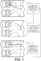
- FIG. 1 illustrates an example process for performing eye detection and/or tracking using multiple imaging devices.
- a system may determine, using first image data generated by a first imaging device 104, a location 106 of a face of a user 108.
- the first imaging device 104 may generate the first image data representing an environment 110.
- the environment 110 may include an interior compartment of a vehicle that includes at least the user 108.
- the environment 110 includes an additional user 112.
- the system may be used in an environment with any number of one or more users.
- the first imaging device 104 includes a first FOV 114 that includes both the user 108 and the additional user 112.
- the system may analyze the first image data using one or more algorithms associated with face detection. Based on the analysis, the system may determine the location 106 of the face of the user 108 within the environment 110 relative to a location of the first imaging device 104.
- the system may determine the location 106 of the face of the user 108 since the user 108 is the driver of the vehicle. In such instances, the system may determine that the user 108 is the driver based on the relative location of the user 108 within the environment 110. For instance, the user 108 may be at a location within the environment 110 at which the driver would normally be located.
- the location 106 may represent a two-dimensional and/or three-dimensional location of the face of the user 108 within the environment 110. Additionally, or alternatively, in some instances, the location 106 may represent a direction 116 from the first imaging device 104 to the face of the user 108. In such instances, the direction 116 may include a two-dimensional vector and/or a three-dimensional vector. In some instances, the second imaging device 120 is placed close to the first imaging device 104 in order to minimize and/or eliminate a parallax error when adjusting the second imaging device 120, as described herein.
- the system may cause, based at least in part on the location 106, a movement of an actuator associated with a second imaging device 120.
- the system may cause the actuator associated with the second imaging device 120 to move from a first position to a second position, which is illustrated by 122. While the actuator is in the second position, the second imaging device 120 may be directed towards the face of the user 108. For instance, a greater portion of a second FOV 124 of the second imaging device 120 may include the face of the user 108 as compared to the first FOV 114 of the first imaging device 118.
- the second imaging device 120 may include a light source. In such instances, while the actuator is in the second position, the light source may be directed towards the face of the face of the user.
- the system may determine, using second image data generated by the second imaging device 120, a position of an eye of the user 108. For instance, the second imaging device 120 may generate the second image data, where the second image data represents at least the face of the user 108. The system may then analyze the second image data using one or more algorithms associated with eye tracking. Based on the analysis, the system may determine the position(s) of the eye(s) of the user 108. In some instances, and also based on the analysis, the system may further determine a gaze direction 128 of the user 108.
- the system may continuously or periodically perform the example process. For instance, the system may determine, using the first image data generated by the first imaging device 104, a new location of the face of the user 108. The system may then cause, based at least in part on the new location, an additional movement of the actuator associated with the second imaging device 120. Additionally, the system may determine, using the second image data generated by the second imaging device 120, a new position of the eye of the user 108 and/or a new gaze direction. In other words, the system may continue to track the eyes of the user 108 over time using the first imaging device 104 and the second imaging device 120.
- FIG. 2 illustrates an example of analyzing image data generated by multiple imaging devices in order to determine an eye position and/or gaze direction of a user 202.
- a system may use a first imaging device may generate first image data.
- the first image data represents at least one image 204 depicting at least the user 202 and an additional user 206.
- the system may then analyze the first image data using one or more algorithms associated with face detection. Based on the analysis, the system may determine a location 208 of the face of the user 202.
- the system may then cause an actuator associated with a second imaging device to move from a first position to a second position, such that the second imaging device is directed towards the face of the user 202. While in the second position, the system may use the second imaging device to generate second image data.
- the second image data represents only a portion of the first image data.
- the second image data represents at least one image 210 depicting the face of the user 202. As shown, a greater portion of the second image data represents the face of the user 202 as compared to the first image data.
- the system may then analyze the second image data using one or more algorithms associated with eye tracking. Based on the analysis, the system may determine at least an eye portion 212 of the user 202 and/or a gaze direction of the user 202. In some instances, the system may then output data representing the location 208 of the face of the user 202, the eye position 212 of the user 202, and/or the gaze direction of the user 202.
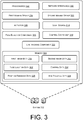
- FIG. 3 illustrates a block diagram of an example system 302 that uses multiple imaging devices for eye tracking.
- the system 302 includes at least a first imaging device 304 (which may represent, and/or be similar to, the first imaging device 104), a second imaging device 306 (which may represent, and/or be similar to, the second imaging device 120), and an actuator 308 that is configured to rotate the second imaging device 306.
- the first imaging device 304 may include a still image camera, a video camera, a digital camera, and/or any other type of device that generates first image data 310.
- the first imaging device 304 may include a wide-angle lens that provides the first imaging device 304 with a wide FOV.
- the second imaging device 306 may include a still image camera, a video camera, a digital camera, and/or any other type of device that generates second image data 312.
- the second imaging device 306 includes a large focal length and/or large depth of field lens that provides the second imaging device 306 with a smaller FOV as compared to the first imaging device 304.
- the system 302 may use the actuator 308 to rotate the second imaging device 306 such that the second imaging device 306 can scan an entirety of the FOV of the first imaging device 304.
- the actuator 308 may include any type of hardware device that is configured to rotate around one or more axis.
- the second imaging device 306 may attach to the actuator 308 such that, when the actuator rotates, the second imaging device 306 also rotates changing the view direction of the second imaging device 306.
- a light source 314 may also be attached to the actuator 308 and/or attached to the second imaging device 306.
- the actuator 308 may further rotate in order to change a direction at which the light source 314 emits light.
- the light source 314 may emit the light in a direction that is similar to the direction at which the second imaging device 306 is generating the second image data 312, such that the light illuminates the FOV of the second imaging device 306.
- the light source 314 may include, but is not limited to, a light-emitting diode, an infrared light source, and/or any other type of light source that emits visible and/or non-visible light.
- a first frame rate and/or first resolution associated with the first imaging device 304 may be different than a second frame rate and/or second resolution associated with the second imaging device 306. In some instances, the first frame rate and/or the first resolution associated with the first imaging device 304 may be the same as the second frame rate and/or the second resolution associated with the second imaging device 306
- the system 302 may include a face detector component 316, a control component 318, and an eye tracking component 320.
- the face detector component 316 may be configured to analyze the first image data 310 in order to determine a location of a face of a user.
- the face detector component 316 may analyze the first image data 310 using one or more algorithms associated with face detection.
- the one or more algorithms may include, but are not limited to, neural network algorithm(s), Principal Component Analysis algorithm(s), Independent Component Analysis algorithms(s), Linear Discriminant Analysis algorithm(s), Evolutionary Pursuit algorithm(s), Elastic Bunch Graph Matching algorithm(s), and/or any other type of algorithm(s) that the face detector component 316 may utilize to perform face detection on the first image data 310.
- the location may correspond to a direction from the first imaging device 304 to the face of the user.
- the face detector component 316 analyzes the first image data 310 using the one or more algorithms. Based on analyses, the face detection component 316 may determine the direction from the first imaging device 310 to the face of the user. The direction may correspond to a two-dimensional vector and/or a three-dimensional vector from the first imaging device 304 to the face of the user. After determining the location of the face of the user, the face detector component 316 may generate face location data 322 representing the location of the face of the user.
- the control component 318 may be configured to use the face location data 322 to move the actuator 308 from a current position to a new position. While in the new position, the second imaging device 306 and/or the light source 314 may be directed at the face of the user. For instance, while in the new position, a greater portion of the FOV of the second imaging device 306 may include the face of the user. Additionally, a greater portion of the light emitted by the light source 314 may be directed at the face of the user than at other objects located within a similar environment as the user. In some instances, to move the actuator 308, the control component 318 may determine the new position based on the location (e.g., the direction) represented by the location data 322.
- control component 318 may use one or more algorithms to determine the new position for the actuator 308.
- the one or more algorithms may determine new position based on the location (and/or direction) represented by the face location data 322, a location of the second imaging device 306, and/or a distance between the first imaging device 304 and the second imaging device 306.
- the control component 318 may determine two-dimensional coordinates indicating a direction from the face to the first imaging device 304, determine a distance from the first imaging device 304 to the face, and convert the two-dimensional coordinates to a three-dimensional vector using the distance, where a specific distance along the vector gives the three-dimensional location of the face.
- the control component 318 may then determine a directional vector between the second imaging device 306 and the face using the three-dimensional vector, the location of the first imaging device 304, and the location of the second imaging device 306. Additionally, the control component 318 may convert the directional vector to polar coordinates that are used to drive the actuator 308. While this is just one example for determining the new position, the control component 318 may use any other techniques to determine the new position for the actuator 308.
- control component 318 may generate control data 324 that represents the new position for the actuator 308.
- control data 324 may represent the polar coordinates that are used to drive the actuator 308.
- the actuator 308 and/or the second imaging device 306 may then use the control data 324 to move from the current position to the new position represented by the control data 324. Additionally, the actuator 308 and/or the second imaging device 306 may generate position feedback data 326 representing the current position of the actuator 308 and/or the second imaging device 306. In some instances, the control component 318 uses the position feedback data 326 to determine when the second imaging device 306 is directed towards the face of the user.
- the control component 318 may analyze the second image data 312 using similar processes as described above with respect to the first image data 310. Based on the analysis, the control component 318 may determine a directional vector between the second imaging device 306 and the face of the user. The control component 318 may then use the directional vector to determine polar coordinates. If the polar coordinates are the same as the polar coordinates determined using the first image data 310 (and/or within a threshold difference), then the control component 318 may determine that the second imaging device 306 is directed at the face of the user.
- control component 318 may use the polar coordinates to further drive the actuator 308.
- the control component 318 may use similar techniques as described above with respect to the first image data 310 in order to further direct the second imaging device 306 at the face of the user.
- the eye tracking component 320 may be configured to analyze the second image data 312 in order to determine eye position and/or a gaze direction of the user.
- the eye tracking component 320 may analyze the second image data 312 using one or more algorithms associated with eye tracking.
- the one or more algorithms may include, but are not limited to, neural network algorithm(s) and/or any other types of algorithm(s) associated with eye tracking.
- the eye position may represent the three-dimensional position of the eye with respect to the second imaging device 306.
- the gaze direction may represent a vector originating from the eye and expressed in a coordinate system associated with the second imaging device 306.
- the eye tracking component 320 may generate eye tracking data 328 representing the eye position and/or gaze direction.
- the second imaging device 306 and/or the control component 318 may then use the eye position and/or gaze direction expressed in the coordinate system associated with the second imaging device 306, the location of the second imaging device 306, and/or the orientation of the second imaging device 306 to determine the eye position and/or gaze direction in a global coordinate system that is associated with the environment. For instance, the second imaging device 306 and/or the control component 318 may determine the eye position and/or gaze direction with respect to the passenger compartment of the vehicle.
- the system 302 includes processor(s) 330, network interface(s) 332, and memory 334.
- a processor such as the processor(s) 330, may include multiple processors and/or a processor having multiple cores. Further, the processors may comprise one or more cores of different types. For example, the processors may include application processor units, graphic processing units, and so forth. In one instance, the processor may comprise a microcontroller and/or a microprocessor.
- the processor(s) 330 may include a graphics processing unit (GPU), a microprocessor, a digital signal processor or other processing units or components known in the art.
- GPU graphics processing unit
- microprocessor a digital signal processor or other processing units or components known in the art.
- the functionally described herein can be performed, at least in part, by one or more hardware logic components.
- illustrative types of hardware logic components include field-programmable gate arrays (FPGAs), application-specific integrated circuits (ASICs), application-specific standard products (ASSPs), system-on-a-chip systems (SOCs), complex programmable logic devices (CPLDs), etc.
- the processor(s) 330 may possess its own local memory, which also may store program components, program data, and/or one or more operating systems.
- the memory 334 may include volatile and nonvolatile memory, removable and non-removable media implemented in any method or technology for storage of information, such as computer-readable instructions, data structures, program component, or other data.
- the memory 334 includes, but is not limited to, RAM, ROM, EEPROM, flash memory or other memory technology, CD-ROM, digital versatile disks (DVD) or other optical storage, magnetic cassettes, magnetic tape, magnetic disk storage or other magnetic storage devices, RAID storage systems, or any other medium which can be used to store the desired information and which can be accessed by a computing device.
- the memory 334 may be implemented as computer-readable storage media ("CRSM”), which may be any available physical media accessible by the processor(s) 330 to execute instructions stored on the memory 334.
- CRSM computer-readable storage media
- CRSM may include random access memory (“RAM”) and Flash memory.
- RAM random access memory
- CRSM may include, but is not limited to, read-only memory (“ROM”), electrically erasable programmable read-only memory (“EEPROM”), or any other tangible medium which can be used to store the desired information and which can be accessed by the processor(s).
- ROM read-only memory
- EEPROM electrically erasable programmable read-only memory
- each respective memory such as the memory 334, discussed herein may include at least one operating system (OS) component that is configured to manage hardware resource devices such as the network interface(s), the I/O devices of the respective apparatuses, and so forth, and provide various services to applications or components executing on the processors.
- OS operating system
- Such OS component may implement a variant of the FreeBSD operating system as promulgated by the FreeBSD Project; other UNIX or UNIX-like variants; a variation of the Linux operating system as promulgated by Linus Torvalds; the FireOS operating system from Amazon.com Inc. of Seattle, Washington, USA; the Windows operating system from Microsoft Corporation of Redmond, Washington, USA; LynxOS as promulgated by Lynx Software Technologies, Inc. of San Jose, California; Operating System Embedded (Enea OSE) as promulgated by ENEA AB of Sweden; RTOS, QNX from Blackberry Limited; and so forth.
- the network interface(s) 332 may enable the system 302 to send data to and/or receive data from other electronic device(s).
- the network interface(s) 332 may include one or more network interface controllers (NICs) or other types of transceiver devices to send and receive data over the network.
- NICs network interface controllers
- the network interface(s) 332 may include a personal area network (PAN) component to enable messages over one or more short-range wireless message channels.
- the PAN component may enable messages compliant with at least one of the following standards IEEE 802.15.4 (ZigBee), IEEE 802.15.1 (Bluetooth), IEEE 802.11 (WiFi), or any other PAN message protocol.
- the network interface(s) 332 may include a wide area network (WAN) component to enable message over a wide area network.
- the network interface(s) may enable the system 302 to communicate using a Controller Area Network bus.
- the operations and/or functionalities associated with and/or described with respect to the components of the system 302 may be performed utilizing cloud-based computing resources.
- web-based systems such as Elastic Compute Cloud systems or similar systems may be utilized to generate and/or present a virtual computing environment for performance of some or all of the functionality described herein.
- one or more systems that may be configured to perform operations without provisioning and/or managing servers, such as a Lambda system or similar system, may be utilized.
- each of the face detector component 316, the control component 318, and the eye tracking component 320 may include software stored in the memory 334.
- the example of FIG. 3 illustrates the face detector component 316 as being separate from the first imaging device 304 and the eye tracking component 320 as being separate from the second imaging device 306, in other examples, the face detector component 316 may be included in the first imaging device 304 and/or the eye tracking component 320 may be included in the second imaging device 306.
- the example of FIG. 3 illustrates the second imaging device 306, the actuator 308, and/or the light source 314 as including separate components, in other examples, the second imaging device 306 may include the actuator 308 and/or the light source 314.
- a machine-learned model which may include, but is not limited to a neural network (e.g., You Only Look Once (YOLO) neural network, VGG, DenseNet, PointNet, convolutional neural network (CNN), stacked auto-encoders, deep Boltzmann machine (DBM), deep belief networks (DBN),), regression algorithm (e.g., ordinary least squares regression (OLSR), linear regression, logistic regression, stepwise regression, multivariate adaptive regression splines (MARS), locally estimated scatterplot smoothing (LOESS)), Bayesian algorithms (e.g., naive Bayes, Gaussian naive Bayes, multinomial naive Bayes, average one-dependence estimators (AODE), Bayesian belief network (BNN), Bayesian networks), clustering algorithms (e.g., k-means, k-medians, expectation maximization (EM), hierarchical clustering), association rule learning algorithms (e.g., perceptr, perceptr
- neural network architectures may include neural networks such as ResNet50, ResNet101, VGG, DenseNet, PointNet, and the like. Although discussed in the context of neural networks, any type of machine-learning may be used consistent with this disclosure.
- machine-learning algorithms may include, but are not limited to, regression algorithms, instance-based algorithms, Bayesian algorithms, association rule learning algorithms, deep learning algorithms, etc.
- FIG. 4 illustrates a diagram representing an example of the system 302 performing eye tracking.
- the first imaging device 304 may generate the first image data 310 and then send the first image data 310 to the face detector component 316.
- the face detector component 316 may then analyze the first image data 310 to determine the location of the face of the user. Additionally, the face detection component 316 may generate the face location data 322 representing the location and send the face location data 322 to the control component 318.
- the control component 318 may use the face location data 322 in order to generate the control data 324, where the control data 324 represents a new position for the second imaging device 306.
- the control component 318 may then send the control data 324 to the second imaging device 306 (and/or the actuator 308).
- the actuator 308 of the second imaging device 306 may move from a current position to the new position. While the actuator is in the new position, the second imaging device 306 may send position feedback data 326 to the control component 318, where the position feedback data 326 indicates that the actuator 308 is in the new position. Additionally, the second imaging device 306 may generate the second image data 312 representing at least the face of the user. The second imaging device 306 may then send the second image data 312 to the face detector component 316.
- the face detector component 316 may analyze the second image data 312 to determine the eyes positions and/or the gaze direction of the user. The face detector component 316 may then generate eye tracking data 328 representing the eyes positions and/or the gaze direction and send the eye tracking data 328 to the control component 318. In some instances, the control component 318 uses the eye tracking data 328, as well as new face location data 322, to determine a new position for the second imaging device 306.
- the control component 318 may send the output data 402 to external system(s) 404.
- the output data 402 may include, but is not limited to, the face location data 322 and/or the eye tracking data 328.
- the external system(s) 404 may be included in a similar device as the system 302.
- the system 302 may be installed in or on a vehicle and the external system(s) 404 may include a vehicle control system.
- the external system(s) 404 may include a remote system (e.g., a fleet monitoring service to monitor drivers, a remote image analysis service, etc. In such instances, the system 302 may send the output data 402 to the external system(s) 404 over a network.
- FIGS. 5-6 illustrate example processes for performing eye tracking.
- the processes described herein are illustrated as collections of blocks in logical flow diagrams, which represent a sequence of operations, some or all of which may be implemented in hardware, software or a combination thereof.
- the blocks may represent computer-executable instructions stored on one or more computer-readable media that, when executed by one or more processors, program the processors to perform the recited operations.
- computer-executable instructions include routines, programs, objects, components, data structures and the like that perform particular functions or implement particular data types.
- the order in which the blocks are described should not be construed as a limitation, unless specifically noted. Any number of the described blocks may be combined in any order and/or in parallel to implement the process, or alternative processes, and not all of the blocks need be executed.
- FIG. 5 illustrates an example process 500 for using multiple imaging devices to perform eye tracking.
- a system may generate, using a first imaging device, first image data representing at least a user.
- the first imaging device may include a first FOV, a first resolution, and/or a first frame rate.
- the system may be installed within a vehicle.
- the first imaging device may be installed in a front portion of the vehicle, such as the dashboard.
- the first image data may then represent the passenger compartment of the vehicle, which includes at least the user (e.g., the driver).
- the system may analyze the first image data using one or more algorithms associated with facial detection and at 506, the system may determine a location of the face of the user.
- the location may represent a direction from the first imaging device to the face of the user.
- the location may represent a two-dimensional vector or a three-dimensional vector indicating the direction from the first imaging device to the face of the user.
- the system determines the location based on which portion of the first image data represents the face of the user.
- the system may cause, based at least in part on the location, an actuator associated with a second imaging device to move from a first position to a second position.
- the actuator may rotate along one or more axis to move from the first position to the second position.
- the second imaging device While in the second position, the second imaging device may be directed towards the face of the user.
- a light source while in the second position, a light source may be directed towards the face of the user.
- the system may generate, using the second imaging device, second image data representing at least an eye of the user. For instance, once the actuator is in the second position, the second imaging device may generate the second image data.
- the second imaging device may include a second FOV, a second resolution, and/or a second frame rate. At least one of the second FOV may be different than the first FOV, the second resolution may be different than the first resolution, or the second frame rate may be different than the first frame rate.
- the second imaging device may also be installed in the front portion of the vehicle, such as the dashboard.
- the system may analyze the second image data using one or more algorithms associated with eye tracking and at 514, the system may determine at least one of an eye position of the user or a gaze direction of the user.
- the system may output data representing at least one of the location of the face of the user, the eye position of the user, or the gaze direction of the user.
- the system may send the data to another system located in a similar device as the system. For instance, if the system is installed in the vehicle, the system may send the data to a vehicle drive system. In some instances, the system may send the data to a remote system over a network connection. In some instances, the system may continue to perform the example process 500 in order to track the eyes of the eyes.
- FIG. 6 illustrates an example process 600 for determining when to adjust an actuator of an imaging device that is being used for eye tracking.
- a system may cause an actuator associated with an imaging device to move to a first position, the first position being associated with a first location within an environment.
- the system may cause the actuator to move to the first position based on determining that a face of a user is located at the first location.
- the first location may be based on a first direction from another imaging device to the face of the user.
- the system may determine a second location associated with a face of a user located within the environment. In some instances, the system may determine the second location by analyzing, using one or more algorithms associated with face detection, image data generated by the other imaging device. In some instances, the system may determine the second location based on receiving, from an electronic device, data indicating the second location. In either instance, the second location may be based on a second direction from the other imaging device to the face of the user.
- the system may determine whether the second location is different than the first location. For instance, the system may compare the second location to the first location. In some instances, comparing the second location to the first location may include comparing the second direction to the first direction. Based on the comparison, the system may determine whether the second location is different than the first location. In some instances, the system may determine that the second location is different than the first location based on a difference between the second direction and the first direction exceeding a threshold in any dimension.
- the threshold may include, but is not limited to, one degree, five degrees, ten degrees, and/or the like.
- the system may determine to leave the actuator in the first position. For instance, if the system determines that the second location is not different than the first location, then the system may determine that the imaging device is still directed towards the face of the user. As such, the system may determine not to move the actuator in order to change the direction of the imaging device. The system may then analyze image data generated by the imaging device in order to determine an eye position and/or gaze direction of the user.
- the system may determine, based at least in part on the second location, a second position for the actuator. For instance, if the system determines that the second location is different than the first location, then the system may determine that the imaging device is no longer directed towards the face of the user. The system may then determine the second position such that the imaging device is directed towards the face of the user, which is now located at the second position. In some instances, the system determines the second position based at least in part on the second location, a location of the other imaging device within the environment, and/or a location of the imaging device within the environment.
- the system may cause the actuator to move from the first position to the second position.
- the imaging device may be directed towards the face of the user, which is located at the second location.
- the system may analyze image data generated by the imaging device to determine the eye position and/or gaze direction of the user. In some instances, the system may then continue to the example process 600 in order to keep the imaging device directed towards the face of the user.
- the FOV 124 of the second imaging device 120, 306 is narrow enough and the resolution of the optical system for the second imaging device 120, 306 is sufficiently high to provide enough image information from the eye region of the user 108, 202 to enable a diameter of one or more of the pupils of the user 108, 202 to be measured.
- Methods for analyzing portions of images such as the region 212 in Figure 2 for iris regions and for identifying pupil boundaries are disclosed in US Patent Application No. 16/410,559 (Ref: FN-643) filed on 13 May 2019 and entitled "Image acquisition system for off-axis eye images”.
- the light source 314 can emit infra-red (IR) or near-IR light and for at least the second imaging device 120, 306 to be sensitive to the wavelengths of light emitted by the light source 314.
- IR infra-red
- the second imaging device 120, 306 and the light source 314 are directed towards the face of the user 108, 202, successive IR images provided by the second imaging device 120, 306 can provide a clear image of the user's pupils even in low ambient light conditions so enabling pupil size and location to be tracked over time.
- one or both of the first imaging device 104, 304 or the second imaging device 120, 306 are sensitive to visible light wavelengths. This can be enabled by providing a Bayer filter type image sensor within the required device where pixels are divided into respective RGB and IR sub-pixels or alternatively, White-IR pixel sensors can be employed.
- visible light spectrum image information received from one or both of the first imaging device 104, 304 or the second imaging device 120, 306 is used to measure the amount of light falling on the user's face, especially the eye region 212.
- the first imaging device 104, 304 is configured to be sensitive to visible light
- this device can be configured to acquire a plurality of images, each at increasing exposure times for any given exposure time of the second imaging device 120, 306.
- HDR high dynamic range
- the illumination of the user's face and especially their eye region 212 can be determined for any given acquired image.
- a photosensor (not shown) with a lens can be used to measure the visible light intensity falling on the user' face including the eye region 212.
- the field of view for the photosensor should be small enough to be limited to the user's face and to exclude any background.
- the photosensor can be mounted in the same housing as the second imaging device 120, 306 so that it also moves and constantly monitors the same part of the environment 110 as the second imaging device 120, 306.
- illumination levels of the user's face including the eye region 212 can then be correlated with pupil size to determine the response of the user to changing light levels incident on their face.
- the eye tracking component 320 itself or indeed any other component such as the control component 318 which is provided with this data can then determine if any of these responses are within a nominal limit for a given user taking into account age, sex, ethnicity and any other relevant information.
- control component 318 or any component which makes such a determination can signal to external systems such as vehicle control system 404 that the user may not be in a suitable state to be controlling the vehicle and appropriate actions can be taken including restricting the speed of the vehicle and/or ensuring the vehicle can be brought to a safe halt.
- the second imaging device 120, 306 could comprise as an alternative to or an addition to a near infra-red (NIR) camera, a narrow field of view thermal camera focused only on a single eye.
- NIR near infra-red
- a visible light illuminator may be provided and can be directed to illuminate the face of at least the user 108,202. So, for example, the illuminator may be actuated by the control component 318 or any other suitable component to emit a light flash of known intensity before the car is started to test the driver's pupil reaction time in order to detect intoxication. Again, if the driver's pupil reaction is outside nominal limits, the control component 318 or any component which makes such a determination can signal to external systems such as vehicle control system 404 that the user may not be in a suitable state to be controlling the vehicle and appropriate actions can be taken.
- Another function of actuating such a visible light illuminator either while a vehicle is being driven or while it is stationary can be the induction of the blink reflex in any of the users 108, 202 or 112, 206 synchronized with the deployment of one or more respective airbags for the or each user to minimize a chance of eye injury by the debris thrown by the airbag(s) in the event of an accident.
- iris information can be extracted from the image data acquired by the second imaging device 120, 306 and provided to a biometric authentication unit, for example, as described in US-2019-364229 (Ref: FN-629), in order to authenticate a user and either to permit the user to control one or more of the functions of the vehicle or to access the user's personal information, such as their age etc. to assist in deciding if they can be permitted to control the vehicle.
- a biometric authentication unit for example, as described in US-2019-364229 (Ref: FN-629)
Abstract
Description
- The present invention relates to a system for performing eye detection and/or tracking.
- Many systems use eye tracking in order to determine gaze directions or other eye related attributes of users. For instance, such as in vehicles, a system may use a camera installed in a vehicle to capture images of users located within the vehicle. The system may then analyze the images to determine at least the gaze direction of the user driving the vehicle. A vehicle control system may then use the gaze direction to determine if the user is paying attention to the road while driving the vehicle. If the user is not paying attention to the road, the vehicle control system may output a sound or other alert to the user.
- In many situations, these systems have problems performing eye tracking to determine the gaze direction or other eye related attributes of the user. For example, such as in large environments like the passenger compartments of vehicles, the camera may require a wide-angle lens to capture images that represent the environment. As such, only a small portion of the images may represent the eyes of the user, which can cause problems for the system analyzing the images using eye tracking. For instance, the system may be unable to identify the eyes of the user using the images. To compensate for this problem, some systems use high-resolution cameras to capture the images. However, using high-resolution cameras may increase processing load, which may increase latency, power consumption, and/or heat generated by the system.
- According to a first aspect there is provided a method according to claim 1.
- Preferably, the method further comprises determining the second position for the actuator based at least in part on the portion of the first image data.
- According to a second aspect, there is provided a method according to claim 14.
- Preferably, the method comprises: generating the first image data comprises generating, using the first imaging device, the first image data using a first frame rate and a first resolution; generating the second image data comprises generating, using the second imaging device, the second image data using a second frame rate and a second resolution; and at least one of the first frame rate is different than the second frame rate, or the first resolution is different than the second resolution.
- Further preferably, the at least one of: the first frame rate is lower than the second frame rate; or the first resolution is lower than the second resolution.
- Preferably, the method comprises determining the second position for the actuator based at least in part on the location of the face of the user and a position of the second imaging device relative to a position of the first imaging device.
- Preferably, in either aspect the method further comprises emitting, using a light source associated with the second imaging device, light towards the face of the user.
- Preferably, in either aspect the first image data further represents a first field of view, FOV, of the first imaging device; the second image data further represents a second FOV of the second imaging device; and the second FOV is smaller than the first FOV.
- In a still further aspect there is provided a system comprising: a first imaging device; a second imaging device; an actuator for positioning the second imaging device; one or more processors; and one or more computer-readable media storing instructions that, when executed by the one or more processors, cause the one or more processors to perform the operations of any of the above aspects.
- The detailed description is set forth with reference to the accompanying figures. In the figures, the left-most digit(s) of a reference number identifies the figure in which the reference number first appears. The use of the same reference numbers in different figures indicates similar or identical items or features.
-
FIG. 1 illustrates an example process for performing eye tracking using multiple imaging devices. -
FIG. 2 illustrates an example of analyzing image data generated by multiple imaging devices in order to determine an eye position and/or gaze direction of a user. -
FIG. 3 illustrates a block diagram of an example system that uses multiple imaging devices for eye tracking. -
FIG. 4 illustrates an example diagram representing a system performing eye tracking. -
FIG. 5 illustrates an example process for using multiple imaging devices to perform eye tracking. -
FIG. 6 illustrates an example process for determining when to adjust an actuator of an imaging device that is being used for eye tracking. - As discussed above, conventional systems that perform eye tracking may use an imaging device, such as a camera, to generate images data representing images. The system may then analyze the image data to determine a gaze direction or other eye related attributes of a user. However, in many situations, such a system may have problems performing eye tracking and/or determining the gaze direction or other eye related attributes of the user. For example, such as when the system is installed in a passenger compartment of a vehicle, the imaging device may require a wide-angle lens to capture images that represent a large portion of the passenger compartment. As such, only a small portion of the image data may represent the eyes of the user, which can limit the system's ability to accurately detect and track the location of the user's eyes and/or gaze direction of the user. To compensate for this problem, some conventional systems use a high-resolution imaging device. However, by using the high-resolution imaging device, such systems typically suffer from higher processing loads to process the high-resolution image data for a wide field of view, which may increase latency, power consumption, and/or heat generated by the system.
- This disclosure describes, in part, systems and techniques for performing eye tracking using multiple imaging devices. For instance, a system may include at least a first imaging device, a second imaging device, and an actuator that is configured to rotate the second imaging device. The first imaging device may include a first field of view (FOV) and the second imaging device may include a second FOV. In some instances, the first FOV is different than the second FOV. For example, the first FOV of the first imaging device may be greater than the second FOV of the second imaging device, such that the second FOV includes only a portion of the first FOV. However, the system may use the actuator to rotate the second imaging device such that the second imaging device can scan substantially all of the first FOV.
- To perform the eye tracking, the system may generate image data (referred to, in these examples, as "first image data") using the first imaging device. The system may then analyze the first image data using one or more algorithms associated with face detection. Based on the analysis, the system may determine a location of a face of a user (e.g., a direction from the first imaging device to the face of the user). For example, based on the analysis, the system may determine that a portion of the first image data represents the face of the user. Each portion of the first image data may be associated with a respective location (and/or respective direction). As such, the system may determine the location (and/or the direction) based on which portion of the first image data represents the face of the user. While this is just one example of determining the location of the face of the user using face detection, in other examples, the system may use any other algorithms and/or techniques to analyze the first image data in order to determine the location of the face of the user.
- The system may then use the location and/or direction of the face of the user to rotate the actuator from a first position to a second position. In the second position, a large portion of the second FOV of the second imaging device may include the face of the user. In other words, the system may use the location determined using the first image data to direct the second imaging device towards the face of the user. Additionally, in some examples, the second imaging device may include a light source that emits light. In such examples, the light source may also be directed towards the face of the user and may emit light in a limited area, such as an area proximate the face of the user. The system may then use the second imaging device to generate image data (referred to, in these examples, as "second image data"). In some instances, and since the second imaging device is directed towards the face of the user, a greater portion of the second image data may represent the face of the user as compared to the first image data. Also, in examples in which the light source emits light in a limited area, less power may be required for the light source than if a larger area (e.g., the passenger compartment or a field of view of the first imaging device) were illuminated.
- The system may then analyze the second image data using one or more algorithms associated with eye tracking. Based on the analysis, the system may determine an eye position and/or in a first aspect, the system may determine a gaze direction of the user. For example, the system may analyze the second image data to identify the center(s) of the pupil(s) of the eye(s) of the user (e.g., the eye(s) position(s)). The system may additionally or alternatively analyze the second image data to determine the center(s) of the corneal reflection(s) created by the light emitted by the light source. Using the location of the face of the user, the center(s) of the pupil(s) of the eye(s), and/or the center(s) of the corneal reflection(s), the system may determine the gaze direction of the user. While this is just one example of determining the gaze direction of the user using eye tracking, in other examples, the system may use any other algorithms and/or techniques to analyze the second image data in order to determine the gaze direction of the user.
- In some instance, the system may perform the techniques above in order to continuously or periodically track the eye position and/or gaze directions of the user. For instance, as the location of the face of the user changes, the system may continue to analyze first image data generated by the first imaging device to determine a new location of the face of the user. The system may then cause the actuator to move from the second position to a third position. While in the third position, the second imaging device and/or the light source may be directed towards the face of the user, which is now located at the new location. The system may then analyze second image data generated by the second imaging device to determine a new eye position and/or in a first aspect, the system may determine a new gaze direction of the user.
- In some instances, the system may output data representing the locations of the face of the user, the eye positions of the user, and/or in a first aspect the gaze directions of the user to one or more computing devices. For instance, if the system is installed in or in communication with a vehicle, the system may output the data to one or more other computing devices installed in the vehicle (e.g., a vehicle drive system) and/or to one or more remote systems via a network connection. The one or more computing devices and/or remote system(s) may then process the data. For instance, the one or more computing devices may analyze the data in order to determine whether the user is paying attention to the road, whether the user is drowsy, whether the user sees an object in an environment of the vehicle, or the like. If the one or more computing devices determine that one of the these or other applicable conditions are present, then the one or more computing devices may cause an alert, such as a sound, vibration, or visible warning, to be output in order to warn the user.
- In some instances, the system may be preinstalled within an environment, such as a passenger compartment of a vehicle. For instance, a manufacturer of the vehicle may preinstall the system into the vehicle and then calibrate the imaging devices based on locations of the imaging devices within the vehicle. In other instances, the system may not be preinstalled within an environment. For instance, the system may include standalone or aftermarket system that may be installed within various environments.
- The second imaging device may be positioned at a known location relative to the first imaging device. In this way, based on the position of the face of the user relative to the first imaging device and the known location of the second imaging device relative to the first imaging device, the system can determine an angle from the second imaging device to the face of the user. In some instances, the second imaging device may be positioned close to the first imaging device. For instance, the second imaging device may be installed within a threshold distance to the first imaging device. The threshold distance may include, but is not limited to, 1 centimeter, 2 centimeters, ten centimeters, and/or the like. In other instances, the second imaging device may be spaced from the first imaging device. For instance, the second imaging device may be spaced a distance greater than the threshold distance from the first imaging device.
- In some instances, when installing the system in a vehicle, the first image device and/or the second image device may be installed in a front portion of the vehicle. For instance, the first imaging device and/or the second imaging device may be installed in, on, or proximate to the dash of the vehicle, the rearview mirror of the vehicle, and/or any other location in which the first imaging device and/or the second imaging device can generate image data representing the eyes of the user driving the vehicle.
- In some instances, by using the system that includes multiple imaging devices to perform eye tracking, the system improves previous systems which only use a single imaging device for performing eye tracking. For example, by directing the second imaging device towards the face of the user, a larger portion of the second image data generated by the second imaging devices represents the face and/or eyes of the user. This makes it easier for the system to analyze the second image data to determine the eye positions and/or in the first aspect gaze directions of the user, as compared to analyzing image data where only a small portion of the image data represents the face and/or eyes of the user. For another example, the system may be able to perform eye tracking using low-resolution imaging devices, which consume less power than a high-resolution imaging device. Not only does this reduce the amount of power consumed by the system, it also reduces the amount of heat that is dissipated by the system, which is important in enclosed or confined spaces such as a dash or rearview mirror of a vehicle.
-
FIG. 1 illustrates an example process for performing eye detection and/or tracking using multiple imaging devices. At 102, a system may determine, using first image data generated by afirst imaging device 104, alocation 106 of a face of auser 108. For instance, thefirst imaging device 104 may generate the first image data representing anenvironment 110. In the example ofFIG. 1 , theenvironment 110 may include an interior compartment of a vehicle that includes at least theuser 108. In the illustrated example, theenvironment 110 includes anadditional user 112. In other examples, the system may be used in an environment with any number of one or more users. As shown, thefirst imaging device 104 includes afirst FOV 114 that includes both theuser 108 and theadditional user 112. To determine thelocation 106 of the face of theuser 108, the system may analyze the first image data using one or more algorithms associated with face detection. Based on the analysis, the system may determine thelocation 106 of the face of theuser 108 within theenvironment 110 relative to a location of thefirst imaging device 104. - In some instances, the system may determine the
location 106 of the face of theuser 108 since theuser 108 is the driver of the vehicle. In such instances, the system may determine that theuser 108 is the driver based on the relative location of theuser 108 within theenvironment 110. For instance, theuser 108 may be at a location within theenvironment 110 at which the driver would normally be located. - In some instances, the
location 106 may represent a two-dimensional and/or three-dimensional location of the face of theuser 108 within theenvironment 110. Additionally, or alternatively, in some instances, thelocation 106 may represent adirection 116 from thefirst imaging device 104 to the face of theuser 108. In such instances, thedirection 116 may include a two-dimensional vector and/or a three-dimensional vector. In some instances, thesecond imaging device 120 is placed close to thefirst imaging device 104 in order to minimize and/or eliminate a parallax error when adjusting thesecond imaging device 120, as described herein. - At 118, the system may cause, based at least in part on the
location 106, a movement of an actuator associated with asecond imaging device 120. For instance, the system may cause the actuator associated with thesecond imaging device 120 to move from a first position to a second position, which is illustrated by 122. While the actuator is in the second position, thesecond imaging device 120 may be directed towards the face of theuser 108. For instance, a greater portion of asecond FOV 124 of thesecond imaging device 120 may include the face of theuser 108 as compared to thefirst FOV 114 of thefirst imaging device 118. Additionally, in some instances, thesecond imaging device 120 may include a light source. In such instances, while the actuator is in the second position, the light source may be directed towards the face of the face of the user. - At 126, the system may determine, using second image data generated by the
second imaging device 120, a position of an eye of theuser 108. For instance, thesecond imaging device 120 may generate the second image data, where the second image data represents at least the face of theuser 108. The system may then analyze the second image data using one or more algorithms associated with eye tracking. Based on the analysis, the system may determine the position(s) of the eye(s) of theuser 108. In some instances, and also based on the analysis, the system may further determine agaze direction 128 of theuser 108. - As further illustrated in the example of
FIG. 1 , the system may continuously or periodically perform the example process. For instance, the system may determine, using the first image data generated by thefirst imaging device 104, a new location of the face of theuser 108. The system may then cause, based at least in part on the new location, an additional movement of the actuator associated with thesecond imaging device 120. Additionally, the system may determine, using the second image data generated by thesecond imaging device 120, a new position of the eye of theuser 108 and/or a new gaze direction. In other words, the system may continue to track the eyes of theuser 108 over time using thefirst imaging device 104 and thesecond imaging device 120. -
FIG. 2 illustrates an example of analyzing image data generated by multiple imaging devices in order to determine an eye position and/or gaze direction of auser 202. For instance, a system may use a first imaging device may generate first image data. In the example ofFIG. 2 , the first image data represents at least oneimage 204 depicting at least theuser 202 and anadditional user 206. The system may then analyze the first image data using one or more algorithms associated with face detection. Based on the analysis, the system may determine alocation 208 of the face of theuser 202. - The system may then cause an actuator associated with a second imaging device to move from a first position to a second position, such that the second imaging device is directed towards the face of the
user 202. While in the second position, the system may use the second imaging device to generate second image data. In the example ofFIG. 2 , the second image data represents only a portion of the first image data. For instance, the second image data represents at least oneimage 210 depicting the face of theuser 202. As shown, a greater portion of the second image data represents the face of theuser 202 as compared to the first image data. - The system may then analyze the second image data using one or more algorithms associated with eye tracking. Based on the analysis, the system may determine at least an
eye portion 212 of theuser 202 and/or a gaze direction of theuser 202. In some instances, the system may then output data representing thelocation 208 of the face of theuser 202, theeye position 212 of theuser 202, and/or the gaze direction of theuser 202. -
FIG. 3 illustrates a block diagram of anexample system 302 that uses multiple imaging devices for eye tracking. As shown, thesystem 302 includes at least a first imaging device 304 (which may represent, and/or be similar to, the first imaging device 104), a second imaging device 306 (which may represent, and/or be similar to, the second imaging device 120), and anactuator 308 that is configured to rotate thesecond imaging device 306. Thefirst imaging device 304 may include a still image camera, a video camera, a digital camera, and/or any other type of device that generatesfirst image data 310. In some instances, thefirst imaging device 304 may include a wide-angle lens that provides thefirst imaging device 304 with a wide FOV. - Additionally, the
second imaging device 306 may include a still image camera, a video camera, a digital camera, and/or any other type of device that generatessecond image data 312. In some instances, thesecond imaging device 306 includes a large focal length and/or large depth of field lens that provides thesecond imaging device 306 with a smaller FOV as compared to thefirst imaging device 304. However, thesystem 302 may use theactuator 308 to rotate thesecond imaging device 306 such that thesecond imaging device 306 can scan an entirety of the FOV of thefirst imaging device 304. - For example, the
actuator 308 may include any type of hardware device that is configured to rotate around one or more axis. Thesecond imaging device 306 may attach to theactuator 308 such that, when the actuator rotates, thesecond imaging device 306 also rotates changing the view direction of thesecond imaging device 306. In some instances, alight source 314 may also be attached to theactuator 308 and/or attached to thesecond imaging device 306. In such instances, theactuator 308 may further rotate in order to change a direction at which thelight source 314 emits light. For example, thelight source 314 may emit the light in a direction that is similar to the direction at which thesecond imaging device 306 is generating thesecond image data 312, such that the light illuminates the FOV of thesecond imaging device 306. Thelight source 314 may include, but is not limited to, a light-emitting diode, an infrared light source, and/or any other type of light source that emits visible and/or non-visible light. - In some instances, a first frame rate and/or first resolution associated with the
first imaging device 304 may be different than a second frame rate and/or second resolution associated with thesecond imaging device 306. In some instances, the first frame rate and/or the first resolution associated with thefirst imaging device 304 may be the same as the second frame rate and/or the second resolution associated with thesecond imaging device 306 - As further illustrated in
FIG. 3 , thesystem 302 may include aface detector component 316, acontrol component 318, and aneye tracking component 320. Theface detector component 316 may be configured to analyze thefirst image data 310 in order to determine a location of a face of a user. For example, theface detector component 316 may analyze thefirst image data 310 using one or more algorithms associated with face detection. The one or more algorithms may include, but are not limited to, neural network algorithm(s), Principal Component Analysis algorithm(s), Independent Component Analysis algorithms(s), Linear Discriminant Analysis algorithm(s), Evolutionary Pursuit algorithm(s), Elastic Bunch Graph Matching algorithm(s), and/or any other type of algorithm(s) that theface detector component 316 may utilize to perform face detection on thefirst image data 310. - In some instances, the location may correspond to a direction from the
first imaging device 304 to the face of the user. For example, to determine the location of the face, theface detector component 316 analyzes thefirst image data 310 using the one or more algorithms. Based on analyses, theface detection component 316 may determine the direction from thefirst imaging device 310 to the face of the user. The direction may correspond to a two-dimensional vector and/or a three-dimensional vector from thefirst imaging device 304 to the face of the user. After determining the location of the face of the user, theface detector component 316 may generateface location data 322 representing the location of the face of the user. - The
control component 318 may be configured to use theface location data 322 to move the actuator 308 from a current position to a new position. While in the new position, thesecond imaging device 306 and/or thelight source 314 may be directed at the face of the user. For instance, while in the new position, a greater portion of the FOV of thesecond imaging device 306 may include the face of the user. Additionally, a greater portion of the light emitted by thelight source 314 may be directed at the face of the user than at other objects located within a similar environment as the user. In some instances, to move theactuator 308, thecontrol component 318 may determine the new position based on the location (e.g., the direction) represented by thelocation data 322. - For example, the
control component 318 may use one or more algorithms to determine the new position for theactuator 308. In some instances, the one or more algorithms may determine new position based on the location (and/or direction) represented by theface location data 322, a location of thesecond imaging device 306, and/or a distance between thefirst imaging device 304 and thesecond imaging device 306. For example, thecontrol component 318 may determine two-dimensional coordinates indicating a direction from the face to thefirst imaging device 304, determine a distance from thefirst imaging device 304 to the face, and convert the two-dimensional coordinates to a three-dimensional vector using the distance, where a specific distance along the vector gives the three-dimensional location of the face. Thecontrol component 318 may then determine a directional vector between thesecond imaging device 306 and the face using the three-dimensional vector, the location of thefirst imaging device 304, and the location of thesecond imaging device 306. Additionally, thecontrol component 318 may convert the directional vector to polar coordinates that are used to drive theactuator 308. While this is just one example for determining the new position, thecontrol component 318 may use any other techniques to determine the new position for theactuator 308. - After determining the position, the
control component 318 may generatecontrol data 324 that represents the new position for theactuator 308. In some instances, thecontrol data 324 may represent the polar coordinates that are used to drive theactuator 308. - The
actuator 308 and/or thesecond imaging device 306 may then use thecontrol data 324 to move from the current position to the new position represented by thecontrol data 324. Additionally, theactuator 308 and/or thesecond imaging device 306 may generateposition feedback data 326 representing the current position of theactuator 308 and/or thesecond imaging device 306. In some instances, thecontrol component 318 uses theposition feedback data 326 to determine when thesecond imaging device 306 is directed towards the face of the user. - In some instances, to determine when the
second imaging device 306 is directed towards the face of the user, thecontrol component 318 may analyze thesecond image data 312 using similar processes as described above with respect to thefirst image data 310. Based on the analysis, thecontrol component 318 may determine a directional vector between thesecond imaging device 306 and the face of the user. Thecontrol component 318 may then use the directional vector to determine polar coordinates. If the polar coordinates are the same as the polar coordinates determined using the first image data 310 (and/or within a threshold difference), then thecontrol component 318 may determine that thesecond imaging device 306 is directed at the face of the user. However, if the polar coordinates are different (e.g., outside of the threshold difference), then thecontrol component 318 may use the polar coordinates to further drive theactuator 308. In other words, thecontrol component 318 may use similar techniques as described above with respect to thefirst image data 310 in order to further direct thesecond imaging device 306 at the face of the user. - The
eye tracking component 320 may be configured to analyze thesecond image data 312 in order to determine eye position and/or a gaze direction of the user. For example, theeye tracking component 320 may analyze thesecond image data 312 using one or more algorithms associated with eye tracking. The one or more algorithms may include, but are not limited to, neural network algorithm(s) and/or any other types of algorithm(s) associated with eye tracking. The eye position may represent the three-dimensional position of the eye with respect to thesecond imaging device 306. Additionally, the gaze direction may represent a vector originating from the eye and expressed in a coordinate system associated with thesecond imaging device 306. After determining the eye position and/or gaze direction of the user, theeye tracking component 320 may generateeye tracking data 328 representing the eye position and/or gaze direction. - In some instances, the
second imaging device 306 and/or thecontrol component 318 may then use the eye position and/or gaze direction expressed in the coordinate system associated with thesecond imaging device 306, the location of thesecond imaging device 306, and/or the orientation of thesecond imaging device 306 to determine the eye position and/or gaze direction in a global coordinate system that is associated with the environment. For instance, thesecond imaging device 306 and/or thecontrol component 318 may determine the eye position and/or gaze direction with respect to the passenger compartment of the vehicle. - As further illustrated in
FIG. 3 , thesystem 302 includes processor(s) 330, network interface(s) 332, andmemory 334. As used herein, a processor, such as the processor(s) 330, may include multiple processors and/or a processor having multiple cores. Further, the processors may comprise one or more cores of different types. For example, the processors may include application processor units, graphic processing units, and so forth. In one instance, the processor may comprise a microcontroller and/or a microprocessor. The processor(s) 330 may include a graphics processing unit (GPU), a microprocessor, a digital signal processor or other processing units or components known in the art. Alternatively, or in addition, the functionally described herein can be performed, at least in part, by one or more hardware logic components. For example, and without limitation, illustrative types of hardware logic components that can be used include field-programmable gate arrays (FPGAs), application-specific integrated circuits (ASICs), application-specific standard products (ASSPs), system-on-a-chip systems (SOCs), complex programmable logic devices (CPLDs), etc. Additionally, the processor(s) 330 may possess its own local memory, which also may store program components, program data, and/or one or more operating systems. - The
memory 334 may include volatile and nonvolatile memory, removable and non-removable media implemented in any method or technology for storage of information, such as computer-readable instructions, data structures, program component, or other data. Thememory 334 includes, but is not limited to, RAM, ROM, EEPROM, flash memory or other memory technology, CD-ROM, digital versatile disks (DVD) or other optical storage, magnetic cassettes, magnetic tape, magnetic disk storage or other magnetic storage devices, RAID storage systems, or any other medium which can be used to store the desired information and which can be accessed by a computing device. Thememory 334 may be implemented as computer-readable storage media ("CRSM"), which may be any available physical media accessible by the processor(s) 330 to execute instructions stored on thememory 334. In one basic instance, CRSM may include random access memory ("RAM") and Flash memory. In other instances, CRSM may include, but is not limited to, read-only memory ("ROM"), electrically erasable programmable read-only memory ("EEPROM"), or any other tangible medium which can be used to store the desired information and which can be accessed by the processor(s). - Further, functional components may be stored in the respective memories, or the same functionality may alternatively be implemented in hardware, firmware, application specific integrated circuits, field programmable gate arrays, or as a system on a chip (SoC). In addition, while not illustrated, each respective memory, such as the
memory 334, discussed herein may include at least one operating system (OS) component that is configured to manage hardware resource devices such as the network interface(s), the I/O devices of the respective apparatuses, and so forth, and provide various services to applications or components executing on the processors. Such OS component may implement a variant of the FreeBSD operating system as promulgated by the FreeBSD Project; other UNIX or UNIX-like variants; a variation of the Linux operating system as promulgated by Linus Torvalds; the FireOS operating system from Amazon.com Inc. of Seattle, Washington, USA; the Windows operating system from Microsoft Corporation of Redmond, Washington, USA; LynxOS as promulgated by Lynx Software Technologies, Inc. of San Jose, California; Operating System Embedded (Enea OSE) as promulgated by ENEA AB of Sweden; RTOS, QNX from Blackberry Limited; and so forth. - The network interface(s) 332 may enable the
system 302 to send data to and/or receive data from other electronic device(s). The network interface(s) 332 may include one or more network interface controllers (NICs) or other types of transceiver devices to send and receive data over the network. For instance, the network interface(s) 332 may include a personal area network (PAN) component to enable messages over one or more short-range wireless message channels. For instance, the PAN component may enable messages compliant with at least one of the following standards IEEE 802.15.4 (ZigBee), IEEE 802.15.1 (Bluetooth), IEEE 802.11 (WiFi), or any other PAN message protocol. Furthermore, the network interface(s) 332 may include a wide area network (WAN) component to enable message over a wide area network. Moreover, the network interface(s) may enable thesystem 302 to communicate using a Controller Area Network bus. - The operations and/or functionalities associated with and/or described with respect to the components of the
system 302 may be performed utilizing cloud-based computing resources. For example, web-based systems such as Elastic Compute Cloud systems or similar systems may be utilized to generate and/or present a virtual computing environment for performance of some or all of the functionality described herein. Additionally, or alternatively, one or more systems that may be configured to perform operations without provisioning and/or managing servers, such as a Lambda system or similar system, may be utilized. - Although the example of
FIG. 3 illustrates each of theface detector component 316, thecontrol component 318, and theeye tracking component 320 as including hardware components, in other examples, one or more of theface detector component 316, thecontrol component 318, and theeye tracking component 320 may include software stored in thememory 334. Additionally, although the example ofFIG. 3 illustrates theface detector component 316 as being separate from thefirst imaging device 304 and theeye tracking component 320 as being separate from thesecond imaging device 306, in other examples, theface detector component 316 may be included in thefirst imaging device 304 and/or theeye tracking component 320 may be included in thesecond imaging device 306. - Furthermore, although the example of
FIG. 3 illustrates thesecond imaging device 306, theactuator 308, and/or thelight source 314 as including separate components, in other examples, thesecond imaging device 306 may include theactuator 308 and/or thelight source 314. - As described herein, a machine-learned model which may include, but is not limited to a neural network (e.g., You Only Look Once (YOLO) neural network, VGG, DenseNet, PointNet, convolutional neural network (CNN), stacked auto-encoders, deep Boltzmann machine (DBM), deep belief networks (DBN),), regression algorithm (e.g., ordinary least squares regression (OLSR), linear regression, logistic regression, stepwise regression, multivariate adaptive regression splines (MARS), locally estimated scatterplot smoothing (LOESS)), Bayesian algorithms (e.g., naive Bayes, Gaussian naive Bayes, multinomial naive Bayes, average one-dependence estimators (AODE), Bayesian belief network (BNN), Bayesian networks), clustering algorithms (e.g., k-means, k-medians, expectation maximization (EM), hierarchical clustering), association rule learning algorithms (e.g., perceptron, back-propagation, Hopfield network, Radial Basis Function Network (RBFN)), supervised learning, unsupervised learning, semi-supervised learning, etc. Additional or alternative examples of neural network architectures may include neural networks such as ResNet50, ResNet101, VGG, DenseNet, PointNet, and the like. Although discussed in the context of neural networks, any type of machine-learning may be used consistent with this disclosure. For example, machine-learning algorithms may include, but are not limited to, regression algorithms, instance-based algorithms, Bayesian algorithms, association rule learning algorithms, deep learning algorithms, etc.
-
FIG. 4 illustrates a diagram representing an example of thesystem 302 performing eye tracking. As shown, thefirst imaging device 304 may generate thefirst image data 310 and then send thefirst image data 310 to theface detector component 316. Theface detector component 316 may then analyze thefirst image data 310 to determine the location of the face of the user. Additionally, theface detection component 316 may generate theface location data 322 representing the location and send theface location data 322 to thecontrol component 318. - The
control component 318 may use theface location data 322 in order to generate thecontrol data 324, where thecontrol data 324 represents a new position for thesecond imaging device 306. Thecontrol component 318 may then send thecontrol data 324 to the second imaging device 306 (and/or the actuator 308). Based on receiving thecontrol data 324, theactuator 308 of thesecond imaging device 306 may move from a current position to the new position. While the actuator is in the new position, thesecond imaging device 306 may sendposition feedback data 326 to thecontrol component 318, where theposition feedback data 326 indicates that theactuator 308 is in the new position. Additionally, thesecond imaging device 306 may generate thesecond image data 312 representing at least the face of the user. Thesecond imaging device 306 may then send thesecond image data 312 to theface detector component 316. - The
face detector component 316 may analyze thesecond image data 312 to determine the eyes positions and/or the gaze direction of the user. Theface detector component 316 may then generateeye tracking data 328 representing the eyes positions and/or the gaze direction and send theeye tracking data 328 to thecontrol component 318. In some instances, thecontrol component 318 uses theeye tracking data 328, as well as newface location data 322, to determine a new position for thesecond imaging device 306. - As further illustrated in the example of
FIG. 4 , thecontrol component 318 may send theoutput data 402 to external system(s) 404. Theoutput data 402 may include, but is not limited to, theface location data 322 and/or theeye tracking data 328. In some instances, the external system(s) 404 may be included in a similar device as thesystem 302. For instance, thesystem 302 may be installed in or on a vehicle and the external system(s) 404 may include a vehicle control system. In some instances, the external system(s) 404 may include a remote system (e.g., a fleet monitoring service to monitor drivers, a remote image analysis service, etc. In such instances, thesystem 302 may send theoutput data 402 to the external system(s) 404 over a network. -
FIGS. 5-6 illustrate example processes for performing eye tracking. The processes described herein are illustrated as collections of blocks in logical flow diagrams, which represent a sequence of operations, some or all of which may be implemented in hardware, software or a combination thereof. In the context of software, the blocks may represent computer-executable instructions stored on one or more computer-readable media that, when executed by one or more processors, program the processors to perform the recited operations. Generally, computer-executable instructions include routines, programs, objects, components, data structures and the like that perform particular functions or implement particular data types. The order in which the blocks are described should not be construed as a limitation, unless specifically noted. Any number of the described blocks may be combined in any order and/or in parallel to implement the process, or alternative processes, and not all of the blocks need be executed. -
FIG. 5 illustrates anexample process 500 for using multiple imaging devices to perform eye tracking. At 502, a system may generate, using a first imaging device, first image data representing at least a user. In some instances, the first imaging device may include a first FOV, a first resolution, and/or a first frame rate. In some instances, the system may be installed within a vehicle. For instance, the first imaging device may be installed in a front portion of the vehicle, such as the dashboard. The first image data may then represent the passenger compartment of the vehicle, which includes at least the user (e.g., the driver). - At 504, the system may analyze the first image data using one or more algorithms associated with facial detection and at 506, the system may determine a location of the face of the user. In some instances, the location may represent a direction from the first imaging device to the face of the user. For instance, the location may represent a two-dimensional vector or a three-dimensional vector indicating the direction from the first imaging device to the face of the user. In some instances, the system determines the location based on which portion of the first image data represents the face of the user.
- At 508, the system may cause, based at least in part on the location, an actuator associated with a second imaging device to move from a first position to a second position. For instance, the actuator may rotate along one or more axis to move from the first position to the second position. While in the second position, the second imaging device may be directed towards the face of the user. Additionally, in some examples, while in the second position, a light source may be directed towards the face of the user.
- At 510, the system may generate, using the second imaging device, second image data representing at least an eye of the user. For instance, once the actuator is in the second position, the second imaging device may generate the second image data. In some instances, the second imaging device may include a second FOV, a second resolution, and/or a second frame rate. At least one of the second FOV may be different than the first FOV, the second resolution may be different than the first resolution, or the second frame rate may be different than the first frame rate. In some instances, such as when the system is installed in the vehicle, the second imaging device may also be installed in the front portion of the vehicle, such as the dashboard.
- At 512, the system may analyze the second image data using one or more algorithms associated with eye tracking and at 514, the system may determine at least one of an eye position of the user or a gaze direction of the user.
- At 516, the system may output data representing at least one of the location of the face of the user, the eye position of the user, or the gaze direction of the user. In some instances, the system may send the data to another system located in a similar device as the system. For instance, if the system is installed in the vehicle, the system may send the data to a vehicle drive system. In some instances, the system may send the data to a remote system over a network connection. In some instances, the system may continue to perform the
example process 500 in order to track the eyes of the eyes. -
FIG. 6 illustrates anexample process 600 for determining when to adjust an actuator of an imaging device that is being used for eye tracking. At 602, a system may cause an actuator associated with an imaging device to move to a first position, the first position being associated with a first location within an environment. In some examples, the system may cause the actuator to move to the first position based on determining that a face of a user is located at the first location. In some instances, the first location may be based on a first direction from another imaging device to the face of the user. - At 604, the system may determine a second location associated with a face of a user located within the environment. In some instances, the system may determine the second location by analyzing, using one or more algorithms associated with face detection, image data generated by the other imaging device. In some instances, the system may determine the second location based on receiving, from an electronic device, data indicating the second location. In either instance, the second location may be based on a second direction from the other imaging device to the face of the user.
- At 606, the system may determine whether the second location is different than the first location. For instance, the system may compare the second location to the first location. In some instances, comparing the second location to the first location may include comparing the second direction to the first direction. Based on the comparison, the system may determine whether the second location is different than the first location. In some instances, the system may determine that the second location is different than the first location based on a difference between the second direction and the first direction exceeding a threshold in any dimension. The threshold may include, but is not limited to, one degree, five degrees, ten degrees, and/or the like.
- If at 606, the system determines that the second location is not different than the first location, then at 608, the system may determine to leave the actuator in the first position. For instance, if the system determines that the second location is not different than the first location, then the system may determine that the imaging device is still directed towards the face of the user. As such, the system may determine not to move the actuator in order to change the direction of the imaging device. The system may then analyze image data generated by the imaging device in order to determine an eye position and/or gaze direction of the user.
- However, if at 606, the system determines that the second location is different than the first location, then at 610, the system may determine, based at least in part on the second location, a second position for the actuator. For instance, if the system determines that the second location is different than the first location, then the system may determine that the imaging device is no longer directed towards the face of the user. The system may then determine the second position such that the imaging device is directed towards the face of the user, which is now located at the second position. In some instances, the system determines the second position based at least in part on the second location, a location of the other imaging device within the environment, and/or a location of the imaging device within the environment.
- At 612, the system may cause the actuator to move from the first position to the second position. As discussed above, when the actuator is at the second position, the imaging device may be directed towards the face of the user, which is located at the second location. Once the actuator is in the second position, the system may analyze image data generated by the imaging device to determine the eye position and/or gaze direction of the user. In some instances, the system may then continue to the
example process 600 in order to keep the imaging device directed towards the face of the user. - Referring back to
Figures 1-3 , in a second aspect of the present invention, as an alternative or in addition to being concerned with a gaze direction of theuser FOV 124 of thesecond imaging device second imaging device user user region 212 inFigure 2 for iris regions and for identifying pupil boundaries are disclosed inUS Patent Application No. 16/410,559 - In such embodiments, it can be beneficial for the
light source 314 to emit infra-red (IR) or near-IR light and for at least thesecond imaging device light source 314. Once thesecond imaging device light source 314 are directed towards the face of theuser second imaging device - In embodiments, one or both of the
first imaging device second imaging device - In any case, visible light spectrum image information received from one or both of the
first imaging device second imaging device eye region 212. - In particular, where the
first imaging device second imaging device user - Knowing the distance of the user's face from the imaging device providing the information, as well as the gain and exposure parameters for the imaging device, the illumination of the user's face and especially their
eye region 212 can be determined for any given acquired image. - Note that in variations of the above described implementation, instead of the imaging device(s) providing illumination information, a photosensor (not shown) with a lens can be used to measure the visible light intensity falling on the user' face including the
eye region 212. The field of view for the photosensor should be small enough to be limited to the user's face and to exclude any background. Thus, the photosensor can be mounted in the same housing as thesecond imaging device environment 110 as thesecond imaging device - In any case, illumination levels of the user's face including the
eye region 212 can then be correlated with pupil size to determine the response of the user to changing light levels incident on their face. - This allows the
system 302 and in particular variations of theeye tracking component 320 to track and one or more of: immediate response to any step change illumination of the user's face, short-term adaptation of the pupil size to illumination level and long-term adaptation of pupil size to illumination level. - The
eye tracking component 320 itself or indeed any other component such as thecontrol component 318 which is provided with this data can then determine if any of these responses are within a nominal limit for a given user taking into account age, sex, ethnicity and any other relevant information. - If not, then the
control component 318 or any component which makes such a determination can signal to external systems such asvehicle control system 404 that the user may not be in a suitable state to be controlling the vehicle and appropriate actions can be taken including restricting the speed of the vehicle and/or ensuring the vehicle can be brought to a safe halt. - In variations of the above described embodiment, the
second imaging device - In the above described embodiment, the component making the determination as to whether a user's pupil response to changes in light was inside a nominal limit or not, was operating continuously during operation of a vehicle and the changes in light level would typically be caused by changes in ambient light level including changes in road lighting.
- In variations of the described embodiment, a visible light illuminator (not shown) may be provided and can be directed to illuminate the face of at least the user 108,202. So, for example, the illuminator may be actuated by the
control component 318 or any other suitable component to emit a light flash of known intensity before the car is started to test the driver's pupil reaction time in order to detect intoxication. Again, if the driver's pupil reaction is outside nominal limits, thecontrol component 318 or any component which makes such a determination can signal to external systems such asvehicle control system 404 that the user may not be in a suitable state to be controlling the vehicle and appropriate actions can be taken. - Another function of actuating such a visible light illuminator either while a vehicle is being driven or while it is stationary can be the induction of the blink reflex in any of the
users - In still further variations of the above described embodiment, iris information can be extracted from the image data acquired by the
second imaging device US-2019-364229 (Ref: FN-629), in order to authenticate a user and either to permit the user to control one or more of the functions of the vehicle or to access the user's personal information, such as their age etc. to assist in deciding if they can be permitted to control the vehicle. - While the foregoing invention is described with respect to the specific examples, it is to be understood that the scope of the invention is not limited to these specific examples. Since other modifications and changes varied to fit particular operating requirements and environments will be apparent to those skilled in the art, the invention is not considered limited to the example chosen for purposes of disclosure, and covers all changes and modifications which do not constitute departures from the true spirit and scope of this invention.
- Although the application describes embodiments having specific structural features and/or methodological acts, it is to be understood that the claims are not necessarily limited to the specific features or acts described. Rather, the specific features and acts are merely illustrative some embodiments that fall within the scope of the claims.
- While various examples and embodiments are described individually herein, the examples and embodiments may be combined, rearranged and modified to arrive at other variations within the scope of this disclosure.
- Although embodiments have been described in language specific to structural features and/or methodological acts, it is to be understood that the disclosure is not necessarily limited to the specific features or acts described. Rather, the specific features and acts are disclosed herein as illustrative forms of implementing the claimed subject matter. Each claim of this document constitutes a separate embodiment, and embodiments that combine different claims and/or different embodiments are within the scope of the disclosure and will be apparent to those of ordinary skill in the art after reviewing this disclosure.
Claims (16)
- A method comprising:a) generating, using a first imaging device, first image data representing a user;b) determining that a portion of the first image data represents a face of the user;c) causing, based at least in part on the portion of the first image data, an actuator associated with a second imaging device to move from a first position to a second position;d) generating, using the second imaging device, second image data representing at least an eye of the user;e) determining, based at least in part the second image data, an eye position of the user; andf) outputting data associated with the eye position of the user.
- The method as recited in claim 1 further comprising:repeating steps a) to e) at successive image generating times including:determining a visible light level incident on said user at each successive image generating time; andusing said second image data to determine a size of at least one of said user'spupils at each successive image generating time, andsaid outputting data comprising outputting data indicating a change in said user's pupil size being outside an expected change for a change in light level from one image generating time to another.
- The method as recited in claim 2, wherein the first and second imaging devices are mounted in a cabin of a vehicle, said first device being configured to image said user when in a driving position for the vehicle, said method further comprising either:performing steps a) to e) when a vehicle is stationary;actuating a visible light source directed toward said user and sufficient to cause a step change in visible light level incident on said user; andrepeating steps a) to e) at least once after said light source is actuated; orrepeating steps a) to e) when a vehicle is in motion.
- The method as recited in claim 2, wherein said change comprises one or more of: a user's immediate response to any step change illumination of the user's face, a short-term adaptation of the pupil size to illumination level; and a long-term adaptation of pupil size to illumination level and preferably said change takes into account at least one or more of a user's: age, sex or ethnicity.
- The method as recited in claim 2 wherein at least one of said first imaging device or said second imaging devices comprises a camera sensitive to at least visible wavelengths, the method preferably comprising using visible wavelength image data to determine said visible light level incident said user.
- The method as recited in claim 2 comprising using a single-cell illumination sensor directed at said user to determine said visible light level incident said user.
- The method as recited in claim 2 wherein said first image data comprises a plurality of image data, each acquired at successively longer exposure times at around the same time as said second image data is generated.
- The method as recited in claim 2 wherein the second imaging device comprises either: a camera sensitive to at least infra-red wavelengths; or a thermal camera configured to image only a single eye region of said user.
- The method as recited in claim 3 comprising:
responsive to determining that said vehicle is likely to be involved in an accident, actuating said visible light source to induce at least said user to blink while at least one vehicle airbag is deployed. - The method as recited in claim 1, further comprising:determining, based at least in part on the portion of the first image data, a direction of the face of the user,wherein causing the actuator to move from the first position to the second position is based at least in part on the direction.
- The method as recited in claim 1, further comprising:determining, based at least in part on the second image data, a gaze direction of the user,wherein the data associated with the eyes position of the user comprises data representing the gaze direction of the user.
- The method as recited in claim 1, wherein:generating the first image data comprises generating, using the first imaging device, the first image data using a first frame rate and a first resolution;generating the second image data comprises generating, using the second imaging device, the second image data using a second frame rate and a second resolution; andat least one of the first frame rate is different than the second frame rate or the first resolution is different than the second resolution.
- The method as recited in claim 1, further comprising:generating, using the first imaging device, third image data representing the user;determining that a portion of the third image data represents the face of the user;causing, based at least in part on the portion of the third image data, the actuator associated with the second imaging device to move from the second position to a third position;generating, using the second imaging device, fourth image data representing at least the eye of the user;determining, based at least in part the fourth image data, an additional eye position of the user; andoutputting additional data associated with the additional eye position of the user.
- A method comprising:generating, using a first imaging device, first image data representing a user;determining, using at least the first image data, a location of a face of the user;causing, based at least in part on the location, an actuator associated with a second imaging device to move the second imaging device from a first position to a second position;generating, using the second imaging device, second image data representing at least an eye of the user;determining, using at least the second image data, a gaze direction of the user; andoutputting data representing the gaze direction of the user.
- The method as recited in claim 14, wherein determining the location of the face of the user comprises:analyzing the first image data using one or more algorithms associated with facial detection;determining, based at least in part on analyzing the first image data, that a portion of the first image data represents the face of the user; anddetermining, based at least in part on the portion of the first image data, the location of the face of the user relative to the second imaging device.
- The method as recited in claim 14, wherein determining the gaze direction of the user comprises:analyzing the second image data using one or more algorithms associated with eye tracking;determining, based at least in part on analyzing the second image data, an eye position of the user; anddetermining, based at least in part on the eye position, the gaze direction of the user.
Applications Claiming Priority (2)
| Application Number | Priority Date | Filing Date | Title |
|---|---|---|---|
| US16/379,348 US10948986B2 (en) | 2019-04-09 | 2019-04-09 | System for performing eye detection and/or tracking |
| US16/719,686 US11046327B2 (en) | 2019-04-09 | 2019-12-18 | System for performing eye detection and/or tracking |
Publications (1)
| Publication Number | Publication Date |
|---|---|
| EP3722993A1 true EP3722993A1 (en) | 2020-10-14 |
Family
ID=69804742
Family Applications (1)
| Application Number | Title | Priority Date | Filing Date |
|---|---|---|---|
| EP20162552.2A Ceased EP3722993A1 (en) | 2019-04-09 | 2020-03-11 | System for performing eye detection and/or tracking |
Country Status (3)
| Country | Link |
|---|---|
| US (1) | US11046327B2 (en) |
| EP (1) | EP3722993A1 (en) |
| CN (1) | CN111798488A (en) |
Cited By (1)
| Publication number | Priority date | Publication date | Assignee | Title |
|---|---|---|---|---|
| WO2023246990A1 (en) * | 2022-06-24 | 2023-12-28 | Continental Engineering Services Gmbh | Method and vehicle control system for setting pleasant temperatures |
Families Citing this family (5)
| Publication number | Priority date | Publication date | Assignee | Title |
|---|---|---|---|---|
| US10948986B2 (en) | 2019-04-09 | 2021-03-16 | Fotonation Limited | System for performing eye detection and/or tracking |
| KR20220000536A (en) * | 2020-06-26 | 2022-01-04 | 현대자동차주식회사 | Apparatus and method for controlling driving of vehicle |
| US11574484B1 (en) * | 2021-01-13 | 2023-02-07 | Ambarella International Lp | High resolution infrared image generation using image data from an RGB-IR sensor and visible light interpolation |
| US11919454B2 (en) * | 2021-02-24 | 2024-03-05 | Subaru Corporation | Occupant monitoring device for vehicle |
| DE102022206389A1 (en) * | 2022-06-24 | 2024-01-04 | Continental Engineering Services Gmbh | Detection system for monitoring the condition of the driver of a motor vehicle |
Citations (3)
| Publication number | Priority date | Publication date | Assignee | Title |
|---|---|---|---|---|
| US5572596A (en) * | 1994-09-02 | 1996-11-05 | David Sarnoff Research Center, Inc. | Automated, non-invasive iris recognition system and method |
| WO2013036632A1 (en) * | 2011-09-09 | 2013-03-14 | Thales Avionics, Inc. | Eye tracking control of vehicle entertainment systems |
| US20190364229A1 (en) | 2018-05-25 | 2019-11-28 | Fotonation Limited | Multispectral image processing system for face detection |
Family Cites Families (18)
| Publication number | Priority date | Publication date | Assignee | Title |
|---|---|---|---|---|
| DE19803158C1 (en) | 1998-01-28 | 1999-05-06 | Daimler Chrysler Ag | Arrangement for determining the state of vigilance, esp. for machinery operator or vehicle driver |
| US6820979B1 (en) | 1999-04-23 | 2004-11-23 | Neuroptics, Inc. | Pupilometer with pupil irregularity detection, pupil tracking, and pupil response detection capability, glaucoma screening capability, intracranial pressure detection capability, and ocular aberration measurement capability |
| JP4469476B2 (en) | 2000-08-09 | 2010-05-26 | パナソニック株式会社 | Eye position detection method and eye position detection apparatus |
| ES2401132T3 (en) * | 2000-10-07 | 2013-04-17 | Metaio Gmbh | Device and procedure for determining the orientation of an eye |
| US7334895B2 (en) | 2002-08-16 | 2008-02-26 | Ontest Corporation | Method, system and device for detecting ocular dysfunctions |
| DE10359125A1 (en) | 2003-12-17 | 2005-07-14 | Volkswagen Ag | Motor vehicle driver`s reflex action recognizing method, involves measuring brightness of ambient light and reflex time taken by pupil of driver against light, and generating threshold value for automatic tiredness estimate of driver |
| CA2685976C (en) | 2007-05-23 | 2013-02-19 | The University Of British Columbia | Methods and apparatus for estimating point-of-gaze in three dimensions |
| CN102725765B (en) * | 2010-01-22 | 2015-06-10 | 虹膜技术公司 | Device and method for iris recognition using a plurality of iris images having different iris sizes |
| US8885882B1 (en) * | 2011-07-14 | 2014-11-11 | The Research Foundation For The State University Of New York | Real time eye tracking for human computer interaction |
| JP5949319B2 (en) | 2012-08-21 | 2016-07-06 | 富士通株式会社 | Gaze detection apparatus and gaze detection method |
| KR102281233B1 (en) | 2013-03-14 | 2021-07-23 | 삼성전자 주식회사 | Apparatus and method controlling display |
| JP2015011579A (en) | 2013-06-28 | 2015-01-19 | 株式会社東芝 | Line-of-sight detector and line-of-sight detection method |
| DE102013221188A1 (en) | 2013-10-18 | 2015-04-23 | Robert Bosch Gmbh | A method for detecting the fatigue of the driver in a vehicle |
| KR101533686B1 (en) | 2014-06-30 | 2015-07-09 | 숭실대학교산학협력단 | Apparatus and method for tracking gaze, recording medium for performing the method |
| US9489739B2 (en) * | 2014-08-13 | 2016-11-08 | Empire Technology Development Llc | Scene analysis for improved eye tracking |
| US10357195B2 (en) | 2017-08-01 | 2019-07-23 | Panasonic Intellectual Property Management Co., Ltd. | Pupillometry and sensor fusion for monitoring and predicting a vehicle operator's condition |
| WO2019204765A1 (en) * | 2018-04-19 | 2019-10-24 | Magic Leap, Inc. | Systems and methods for operating a display system based on user perceptibility |
| US10948986B2 (en) | 2019-04-09 | 2021-03-16 | Fotonation Limited | System for performing eye detection and/or tracking |
-
2019
- 2019-12-18 US US16/719,686 patent/US11046327B2/en active Active
-
2020
- 2020-03-11 EP EP20162552.2A patent/EP3722993A1/en not_active Ceased
- 2020-04-08 CN CN202010269020.4A patent/CN111798488A/en active Pending
Patent Citations (3)
| Publication number | Priority date | Publication date | Assignee | Title |
|---|---|---|---|---|
| US5572596A (en) * | 1994-09-02 | 1996-11-05 | David Sarnoff Research Center, Inc. | Automated, non-invasive iris recognition system and method |
| WO2013036632A1 (en) * | 2011-09-09 | 2013-03-14 | Thales Avionics, Inc. | Eye tracking control of vehicle entertainment systems |
| US20190364229A1 (en) | 2018-05-25 | 2019-11-28 | Fotonation Limited | Multispectral image processing system for face detection |
Non-Patent Citations (1)
| Title |
|---|
| BEYMER D ET AL: "Eye gaze tracking using an active stereo head", PROCEEDINGS / 2003 IEEE COMPUTER SOCIETY CONFERENCE ON COMPUTER VISION AND PATTERN RECOGNITION, 18 - 20 JUNE 2003, MADISON, WISCONSIN; [PROCEEDINGS OF THE IEEE COMPUTER CONFERENCE ON COMPUTER VISION AND PATTERN RECOGNITION], LOS ALAMITOS, CALIF. [U.A, vol. 2, 18 June 2003 (2003-06-18), pages 451 - 458, XP010644705, ISBN: 978-0-7695-1900-5, DOI: 10.1109/CVPR.2003.1211502 * |
Cited By (1)
| Publication number | Priority date | Publication date | Assignee | Title |
|---|---|---|---|---|
| WO2023246990A1 (en) * | 2022-06-24 | 2023-12-28 | Continental Engineering Services Gmbh | Method and vehicle control system for setting pleasant temperatures |
Also Published As
| Publication number | Publication date |
|---|---|
| US20200324780A1 (en) | 2020-10-15 |
| CN111798488A (en) | 2020-10-20 |
| US11046327B2 (en) | 2021-06-29 |
Similar Documents
| Publication | Publication Date | Title |
|---|---|---|
| EP3722993A1 (en) | System for performing eye detection and/or tracking | |
| US10948986B2 (en) | System for performing eye detection and/or tracking | |
| JP7216672B2 (en) | Visual, Depth, and Microvibration Data Extraction Using an Integrated Imager | |
| US11535280B2 (en) | Method and device for determining an estimate of the capability of a vehicle driver to take over control of a vehicle | |
| EP3222467B1 (en) | Device and method for controlling the interior lighting of a vehicle with gesture recognition and optionally voice recognition | |
| US11386709B2 (en) | System and method for improving signal to noise ratio in object tracking under poor light conditions | |
| EP3060434B1 (en) | Responding to in-vehicle environmental conditions | |
| EP2288287B1 (en) | Driver imaging apparatus and driver imaging method | |
| US11455810B2 (en) | Driver attention state estimation | |
| WO2018009552A1 (en) | System and method for image analysis | |
| US10604063B2 (en) | Control device for vehicle headlight | |
| JP6698963B2 (en) | Passenger status detection device, passenger status detection system, and passenger status detection method | |
| US20220377223A1 (en) | High performance bright pupil eye tracking | |
| JP2017027604A (en) | Method and device for estimating direction of view of vehicle occupant, and method and device for determining head movement gain parameter specific for vehicle occupant | |
| US20240096116A1 (en) | Devices and methods for detecting drowsiness of drivers of vehicles | |
| CN115719486A (en) | Context-based state estimation | |
| WO2022150874A1 (en) | System and method for skin detection in images | |
| WO2021262166A1 (en) | Operator evaluation and vehicle control based on eyewear data | |
| CN115380262A (en) | Multi-mode eye tracking with independently operable illuminators | |
| JP2021527980A (en) | High frame rate image preprocessing system and method | |
| US20230373508A1 (en) | Monitoring device, storage medium storing computer program for monitoring, and monitoring method | |
| JP2023084580A (en) | Hand area detection device, hand area detection method and computer program for hand area detection | |
| JP2022018497A (en) | Information recording device, information recording method and information recording system | |
| CN117953333A (en) | Biometric service assessment architecture for vehicles |
Legal Events
| Date | Code | Title | Description |
|---|---|---|---|
| PUAI | Public reference made under article 153(3) epc to a published international application that has entered the european phase |
Free format text: ORIGINAL CODE: 0009012 |
|
| STAA | Information on the status of an ep patent application or granted ep patent |
Free format text: STATUS: THE APPLICATION HAS BEEN PUBLISHED |
|
| AK | Designated contracting states |
Kind code of ref document: A1 Designated state(s): AL AT BE BG CH CY CZ DE DK EE ES FI FR GB GR HR HU IE IS IT LI LT LU LV MC MK MT NL NO PL PT RO RS SE SI SK SM TR |
|
| AX | Request for extension of the european patent |
Extension state: BA ME |
|
| STAA | Information on the status of an ep patent application or granted ep patent |
Free format text: STATUS: REQUEST FOR EXAMINATION WAS MADE |
|
| 17P | Request for examination filed |
Effective date: 20201027 |
|
| RBV | Designated contracting states (corrected) |
Designated state(s): AL AT BE BG CH CY CZ DE DK EE ES FI FR GB GR HR HU IE IS IT LI LT LU LV MC MK MT NL NO PL PT RO RS SE SI SK SM TR |
|
| STAA | Information on the status of an ep patent application or granted ep patent |
Free format text: STATUS: EXAMINATION IS IN PROGRESS |
|
| 17Q | First examination report despatched |
Effective date: 20211006 |
|
| STAA | Information on the status of an ep patent application or granted ep patent |
Free format text: STATUS: THE APPLICATION HAS BEEN REFUSED |
|
| 18R | Application refused |
Effective date: 20230921 |