EP3718796B1 - Evaluation system for the condition evaluation of a passenger - Google Patents
Evaluation system for the condition evaluation of a passenger Download PDFInfo
- Publication number
- EP3718796B1 EP3718796B1 EP19167631.1A EP19167631A EP3718796B1 EP 3718796 B1 EP3718796 B1 EP 3718796B1 EP 19167631 A EP19167631 A EP 19167631A EP 3718796 B1 EP3718796 B1 EP 3718796B1
- Authority
- EP
- European Patent Office
- Prior art keywords
- parameter
- passenger
- cabin
- ref
- vehicle
- Prior art date
- Legal status (The legal status is an assumption and is not a legal conclusion. Google has not performed a legal analysis and makes no representation as to the accuracy of the status listed.)
- Active
Links
- 238000011156 evaluation Methods 0.000 title claims description 210
- 230000037323 metabolic rate Effects 0.000 claims description 35
- 230000036387 respiratory rate Effects 0.000 claims description 33
- 238000009529 body temperature measurement Methods 0.000 claims description 26
- 238000005259 measurement Methods 0.000 claims description 26
- 230000036651 mood Effects 0.000 claims description 23
- 230000003287 optical effect Effects 0.000 claims description 22
- 210000001061 forehead Anatomy 0.000 claims description 14
- 230000001815 facial effect Effects 0.000 claims description 13
- 238000000034 method Methods 0.000 claims description 9
- 230000005855 radiation Effects 0.000 claims description 7
- 238000002329 infrared spectrum Methods 0.000 claims description 6
- 230000007257 malfunction Effects 0.000 claims description 6
- 230000002123 temporal effect Effects 0.000 claims description 6
- 230000009466 transformation Effects 0.000 claims description 6
- 238000012544 monitoring process Methods 0.000 claims description 5
- 238000004422 calculation algorithm Methods 0.000 claims description 4
- 210000003128 head Anatomy 0.000 claims description 4
- 238000001429 visible spectrum Methods 0.000 claims description 4
- 230000017531 blood circulation Effects 0.000 claims description 3
- 210000004204 blood vessel Anatomy 0.000 claims description 3
- 238000004891 communication Methods 0.000 claims description 3
- 210000004709 eyebrow Anatomy 0.000 claims description 3
- 238000010438 heat treatment Methods 0.000 claims description 3
- 230000000241 respiratory effect Effects 0.000 claims description 3
- 238000004378 air conditioning Methods 0.000 claims description 2
- 230000004438 eyesight Effects 0.000 claims description 2
- 238000009423 ventilation Methods 0.000 claims description 2
- 230000006870 function Effects 0.000 description 19
- 238000010586 diagram Methods 0.000 description 6
- 238000013500 data storage Methods 0.000 description 4
- 230000035807 sensation Effects 0.000 description 4
- 230000005457 Black-body radiation Effects 0.000 description 2
- 230000001419 dependent effect Effects 0.000 description 2
- 230000007613 environmental effect Effects 0.000 description 2
- 208000010496 Heart Arrest Diseases 0.000 description 1
- QVGXLLKOCUKJST-UHFFFAOYSA-N atomic oxygen Chemical compound [O] QVGXLLKOCUKJST-UHFFFAOYSA-N 0.000 description 1
- 238000004364 calculation method Methods 0.000 description 1
- 238000001816 cooling Methods 0.000 description 1
- 238000013461 design Methods 0.000 description 1
- 238000001514 detection method Methods 0.000 description 1
- 238000002565 electrocardiography Methods 0.000 description 1
- 239000004744 fabric Substances 0.000 description 1
- 230000004907 flux Effects 0.000 description 1
- 230000004927 fusion Effects 0.000 description 1
- 230000036541 health Effects 0.000 description 1
- 230000000977 initiatory effect Effects 0.000 description 1
- 230000010354 integration Effects 0.000 description 1
- 238000007726 management method Methods 0.000 description 1
- 208000010125 myocardial infarction Diseases 0.000 description 1
- 230000004297 night vision Effects 0.000 description 1
- 229910052760 oxygen Inorganic materials 0.000 description 1
- 239000001301 oxygen Substances 0.000 description 1
- 238000002106 pulse oximetry Methods 0.000 description 1
- 230000009467 reduction Effects 0.000 description 1
- 238000004088 simulation Methods 0.000 description 1
- 238000010257 thawing Methods 0.000 description 1
- 230000001131 transforming effect Effects 0.000 description 1
Images


Classifications
-
- A—HUMAN NECESSITIES
- A61—MEDICAL OR VETERINARY SCIENCE; HYGIENE
- A61B—DIAGNOSIS; SURGERY; IDENTIFICATION
- A61B5/00—Measuring for diagnostic purposes; Identification of persons
- A61B5/48—Other medical applications
- A61B5/4866—Evaluating metabolism
-
- B—PERFORMING OPERATIONS; TRANSPORTING
- B60—VEHICLES IN GENERAL
- B60H—ARRANGEMENTS OF HEATING, COOLING, VENTILATING OR OTHER AIR-TREATING DEVICES SPECIALLY ADAPTED FOR PASSENGER OR GOODS SPACES OF VEHICLES
- B60H1/00—Heating, cooling or ventilating [HVAC] devices
- B60H1/00642—Control systems or circuits; Control members or indication devices for heating, cooling or ventilating devices
- B60H1/00735—Control systems or circuits characterised by their input, i.e. by the detection, measurement or calculation of particular conditions, e.g. signal treatment, dynamic models
- B60H1/00742—Control systems or circuits characterised by their input, i.e. by the detection, measurement or calculation of particular conditions, e.g. signal treatment, dynamic models by detection of the vehicle occupants' presence; by detection of conditions relating to the body of occupants, e.g. using radiant heat detectors
-
- A—HUMAN NECESSITIES
- A61—MEDICAL OR VETERINARY SCIENCE; HYGIENE
- A61B—DIAGNOSIS; SURGERY; IDENTIFICATION
- A61B5/00—Measuring for diagnostic purposes; Identification of persons
- A61B5/08—Detecting, measuring or recording devices for evaluating the respiratory organs
- A61B5/0816—Measuring devices for examining respiratory frequency
-
- A—HUMAN NECESSITIES
- A61—MEDICAL OR VETERINARY SCIENCE; HYGIENE
- A61B—DIAGNOSIS; SURGERY; IDENTIFICATION
- A61B5/00—Measuring for diagnostic purposes; Identification of persons
- A61B5/16—Devices for psychotechnics; Testing reaction times ; Devices for evaluating the psychological state
- A61B5/165—Evaluating the state of mind, e.g. depression, anxiety
-
- A—HUMAN NECESSITIES
- A61—MEDICAL OR VETERINARY SCIENCE; HYGIENE
- A61B—DIAGNOSIS; SURGERY; IDENTIFICATION
- A61B5/00—Measuring for diagnostic purposes; Identification of persons
- A61B5/68—Arrangements of detecting, measuring or recording means, e.g. sensors, in relation to patient
- A61B5/6887—Arrangements of detecting, measuring or recording means, e.g. sensors, in relation to patient mounted on external non-worn devices, e.g. non-medical devices
- A61B5/6893—Cars
-
- A—HUMAN NECESSITIES
- A61—MEDICAL OR VETERINARY SCIENCE; HYGIENE
- A61B—DIAGNOSIS; SURGERY; IDENTIFICATION
- A61B5/00—Measuring for diagnostic purposes; Identification of persons
- A61B5/72—Signal processing specially adapted for physiological signals or for diagnostic purposes
-
- A—HUMAN NECESSITIES
- A61—MEDICAL OR VETERINARY SCIENCE; HYGIENE
- A61B—DIAGNOSIS; SURGERY; IDENTIFICATION
- A61B5/00—Measuring for diagnostic purposes; Identification of persons
- A61B5/72—Signal processing specially adapted for physiological signals or for diagnostic purposes
- A61B5/7271—Specific aspects of physiological measurement analysis
-
- B—PERFORMING OPERATIONS; TRANSPORTING
- B60—VEHICLES IN GENERAL
- B60R—VEHICLES, VEHICLE FITTINGS, OR VEHICLE PARTS, NOT OTHERWISE PROVIDED FOR
- B60R16/00—Electric or fluid circuits specially adapted for vehicles and not otherwise provided for; Arrangement of elements of electric or fluid circuits specially adapted for vehicles and not otherwise provided for
- B60R16/02—Electric or fluid circuits specially adapted for vehicles and not otherwise provided for; Arrangement of elements of electric or fluid circuits specially adapted for vehicles and not otherwise provided for electric constitutive elements
- B60R16/037—Electric or fluid circuits specially adapted for vehicles and not otherwise provided for; Arrangement of elements of electric or fluid circuits specially adapted for vehicles and not otherwise provided for electric constitutive elements for occupant comfort, e.g. for automatic adjustment of appliances according to personal settings, e.g. seats, mirrors, steering wheel
-
- G—PHYSICS
- G01—MEASURING; TESTING
- G01J—MEASUREMENT OF INTENSITY, VELOCITY, SPECTRAL CONTENT, POLARISATION, PHASE OR PULSE CHARACTERISTICS OF INFRARED, VISIBLE OR ULTRAVIOLET LIGHT; COLORIMETRY; RADIATION PYROMETRY
- G01J5/00—Radiation pyrometry, e.g. infrared or optical thermometry
-
- G—PHYSICS
- G01—MEASURING; TESTING
- G01K—MEASURING TEMPERATURE; MEASURING QUANTITY OF HEAT; THERMALLY-SENSITIVE ELEMENTS NOT OTHERWISE PROVIDED FOR
- G01K13/00—Thermometers specially adapted for specific purposes
- G01K13/02—Thermometers specially adapted for specific purposes for measuring temperature of moving fluids or granular materials capable of flow
- G01K13/028—Thermometers specially adapted for specific purposes for measuring temperature of moving fluids or granular materials capable of flow for use in total air temperature [TAT] probes
-
- G—PHYSICS
- G16—INFORMATION AND COMMUNICATION TECHNOLOGY [ICT] SPECIALLY ADAPTED FOR SPECIFIC APPLICATION FIELDS
- G16H—HEALTHCARE INFORMATICS, i.e. INFORMATION AND COMMUNICATION TECHNOLOGY [ICT] SPECIALLY ADAPTED FOR THE HANDLING OR PROCESSING OF MEDICAL OR HEALTHCARE DATA
- G16H50/00—ICT specially adapted for medical diagnosis, medical simulation or medical data mining; ICT specially adapted for detecting, monitoring or modelling epidemics or pandemics
- G16H50/30—ICT specially adapted for medical diagnosis, medical simulation or medical data mining; ICT specially adapted for detecting, monitoring or modelling epidemics or pandemics for calculating health indices; for individual health risk assessment
-
- B—PERFORMING OPERATIONS; TRANSPORTING
- B60—VEHICLES IN GENERAL
- B60H—ARRANGEMENTS OF HEATING, COOLING, VENTILATING OR OTHER AIR-TREATING DEVICES SPECIALLY ADAPTED FOR PASSENGER OR GOODS SPACES OF VEHICLES
- B60H1/00—Heating, cooling or ventilating [HVAC] devices
- B60H1/00642—Control systems or circuits; Control members or indication devices for heating, cooling or ventilating devices
- B60H1/00735—Control systems or circuits characterised by their input, i.e. by the detection, measurement or calculation of particular conditions, e.g. signal treatment, dynamic models
- B60H1/00807—Control systems or circuits characterised by their input, i.e. by the detection, measurement or calculation of particular conditions, e.g. signal treatment, dynamic models the input being a specific way of measuring or calculating an air or coolant temperature
Definitions
- the present invention refers to an evaluation system for the condition evaluation of a vehicle passenger, and to a method for evaluating the condition of a vehicle passenger.
- HVAC heating ventilation and air conditioning system
- HVAC heating ventilation and air conditioning system
- HVAC heating ventilation and air conditioning system
- Passenger comfort is currently assumed at a certain air temperature and associated airflow inside the vehicle cabin, which can be selected and interactively changed by the passenger through the EATC control head.
- the passenger may select an interior temperature setting, which is expected to generate a comfortable climate within a certain period of time.
- the vehicle cabin climate is expected to stay comfortable during the respective trip. Changing parameters during the trip, such as vehicle speed, ambient conditions, sun load, tunnels, or the like must be compensated by the EATC, preferably without any impact to the passenger comfort.
- the very indirect way of calibration may still cause passenger discomfort under certain conditions, particularly in case of unsuitable calibration or in case of conditions not considered for calibration.
- infrared sensors are typically cost intensive. This particularly holds true for infrared sensors with a high resolution. Furthermore, the correlation between infrared measurements and discharge temperatures of a HVAC system may still lead to passenger discomfort under certain conditions.
- An evaluation system is configured for the condition evaluation of a vehicle passenger.
- a condition evaluation may, for example, refer to a comfort condition and/or an emergency condition of a vehicle passenger, but is not limited thereto.
- the evaluation system comprises a parameter evaluation device being configured to evaluate a plurality of parameters of a set of vehicle interior and vehicle passenger parameters, the set of parameters including:
- the evaluation system furthermore comprises a condition value evaluation device being configured to evaluate a passenger condition value based on the parameters evaluated by the parameter evaluation unit.
- the condition value evaluation device is configured to apply a weighting factor for a parameter evaluated by the parameter evaluation device. Said weighting factor is within one of the ranges of: ⁇ 10 ⁇ a ⁇ 10 , ⁇ 10 ⁇ b ⁇ 10 , 0 ⁇ c ⁇ 8 , 0 ⁇ d ⁇ 8 , 0 ⁇ e ⁇ 5 , ⁇ 1 ⁇ f ⁇ 0 , and 0.2 ⁇ g ⁇ 3 ; where:
- a passenger condition value representing detailed condition information may be evaluated.
- the system allows a flexible and highly individualized condition evaluation, particularly in view of a high number of relevant parameters, while at the same time ensuring their suitable and/or precise consideration for different vehicle functionalities, such as the functionality of an HVAC system, an interior lighting system, an infotainment system, an emergency system and/or other systems of a vehicle.
- vehicle functionalities such as the functionality of an HVAC system, an interior lighting system, an infotainment system, an emergency system and/or other systems of a vehicle.
- the consideration of a rather high number of detected and/or evaluated parameters widens the data base on a passengers state and/or a vehicle interior state, and subsequently allows to improve the respective functionalities of the vehicle, particularly comfort related functionalities.
- the term "passenger” may refer to occupants in general, including, for example, a driver, a co-driver, and/or a rear-passenger.
- At least one weighting factor for a parameter evaluated by the by the parameter evaluation device may be within the range of ⁇ 8 ⁇ a ⁇ 8 , ⁇ 7 ⁇ a ⁇ 7 , ⁇ 8 ⁇ b ⁇ 8 , ⁇ 7 ⁇ b ⁇ 7 , 0 ⁇ c ⁇ 6 , 0 ⁇ c ⁇ 5 , 0.2 ⁇ c ⁇ 5 , 0 ⁇ d ⁇ 6 , 0 ⁇ d ⁇ 5 , 1 ⁇ d ⁇ 5 , 0 ⁇ e ⁇ 4 , 0 ⁇ e ⁇ 3 , 0.6 ⁇ e ⁇ 3 , ⁇ 0.5 ⁇ f ⁇ 0 , ⁇ 0.3 ⁇ f ⁇ 0 , 0.3 ⁇ g ⁇ 2 and/or 0.5 ⁇ g ⁇ 1 ;
- the condition value evaluation device is configured to evaluate a passenger comfort condition value, for example a thermal sensation vote.
- the evaluation system may particularly be suitable for providing a condition value as an input factor for the HVAC system of a vehicle.
- the passenger comfort may thereby suitably improved.
- Individual comfort assessment for each passenger, represented by a passenger comfort condition value, for example in the form of a thermal sensation vote, may be used for individual control of discharge temperature, air distribution and/or air velocity of an HVAC system, and therewith improve the comfort of the respective vehicle passenger.
- condition value evaluation device may be configured to evaluate a passenger emergency condition value.
- a passenger emergency condition value for example, representing an health emergency such as a heart attack or cardiac arrest
- a vehicle emergency system may for example be configured for the initiation of an automated emergency call. Passenger safety may therewith be improved.
- condition value evaluation device may be configured to provide the evaluated condition value to an electronic automatic temperature control system (EATC) and/or to an infotainment and/or communication system of a vehicle.
- EATC electronic automatic temperature control system
- An EATC system may use the condition value for automated temperature control, and a communication system may use an emergency related condition value for a possible emergency related operation, such as an emergency call.
- the functionality may therewith be further enhanced.
- condition value evaluation device may be configured to evaluate a passenger condition value based on a plurality of remaining parameters evaluated by the parameter evaluation unit in case of any missing parameter and/or any parameter evaluation malfunction.
- the operational safety of the evaluation system may thereby be improved, particularly avoiding a total malfunction due to the missing of single parameters and/or single parameter evaluation malfunctions.
- condition value evaluation device may be configured to apply a predefined substitute parameter value for any missing parameter and/or in case of any parameter evaluation malfunction. That is, in case an intended parameter evaluation is not successful, a predefined substitute parameter value may be applied, in order to avoid significant falsifications of the final condition value.
- a predefined substitute parameter value may be saved permanently within the parameter evaluation device and/or within the condition value evaluation device and/or adapted automatically and/or manually.
- condition value evaluation device may be configured to apply a weighting factor for each substitute parameter value, said weighting factor corresponding to the weighting factor of the substituted parameter. That is, in case of application of a substitute parameter value, the same weighting factor, which would have been applied for the corresponding parameter, is applied for the substitute parameter value. The risk of falsifications of the final condition value may therewith be further reduced.
- condition value evaluation device may be configured to evaluate a passenger condition value based on at least one predefined parameter reference value, the reference value being within one of the ranges of: 16 ° C ⁇ T cabin , air , ref ⁇ 26 ° C , 16 ° C ⁇ T cabin , rad , ref ⁇ 26 ° C , 1 ⁇ MR ref ⁇ 1.6 , 0.8 ⁇ CL ref ⁇ 1.5 , and/or 12 ⁇ RR ref ⁇ 15 , where
- the evaluation precision may be further improved.
- the above mentioned parameter reference values may be saved permanently within the parameter evaluation device and/or within the condition value evaluation device.
- the parameter reference values may be adaptable automatically and/or manually and/or be permanently fixed to a predefined value, particularly unchangeable by a vehicle passenger.
- the parameter evaluation device may be configured to evaluate a vehicle cabin air temperature parameter based on at least one temperature measurement of a vehicle interior surface, preferably of a surface with low thermal inertia. Further preferred, the parameter evaluation device may be configured to evaluate a vehicle cabin air temperature parameter based on at least one temperature measurement of a fabric surface and/or a headrest surface and/or a backrest surface and/or a roof lining surface. Such temperature measurement may be conducted with limited effort and high operational safety.
- the parameter evaluation device may be configured to evaluate a vehicle cabin air temperature parameter based on a plurality of temperature measurements of different vehicle interior surfaces. The evaluation accuracy may thereby be improved.
- Evaluations of a vehicle cabin air temperature parameter based on this function may be conducted with only little effort, while at the same time providing sufficiently accurate results.
- the parameter evaluation device may be configured to evaluate a vehicle cabin surface temperature parameter based on at least one temperature measurement of a vehicle interior surface, preferably based on at least one temperature measurement of vehicle cabin surface .
- the parameter evaluation device may be configured to evaluate a vehicle cabin surface temperature parameter based on at least one temperature measurement of a dashboard, a ceiling portion, a window portion, and/or a door portion.
- Such surface portions may have a particularly high thermal inertia, and may therefore provide precise information on the surface temperatures within a vehicle cabin and/or temperature radiation from such surfaces.
- the emissivity coefficient of the respective surface portion may be previously determined and/or suitably predefined and/or permanently saved within the parameter evaluation device and/or within the condition value evaluation device. This allows to accurately assess the respective surface temperature and/or the respective surface temperature parameter.
- the vehicle cabin surface temperature parameter weighting factor may be based on at least one or a plurality of emissivity values of respective surfaces. The evaluation accuracy may thereby further improved.
- the parameter evaluation device may be configured to evaluate a vehicle cabin surface temperature radiation parameter. That is, any evaluated vehicle cabin surface temperature parameter may be a vehicle cabin surface temperature radiation parameter. Accordingly, the evaluated parameter may represent any possible temperature radiation from cabin surfaces.
- the parameter evaluation device may be configured to evaluate a vehicle cabin surface temperature parameter based on a plurality of temperature measurements of different vehicle interior surfaces.
- the evaluation accuracy may be further improved and the risk of falsifications by single measurements reduced.
- Evaluations of a surface temperature parameter based on this functions may be conducted with only little effort, while at the same time providing sufficiently accurate results.
- the parameter evaluation device may be configured to evaluate a thermal body state parameter, a metabolic rate parameter, a clothing level parameter and/or a respiratory rate parameter based on at least one computer vision algorithm and/or based on at least one measurement of a passenger's head and/or other body parts.
- a thermal body state parameter e.g., a thermal body state parameter
- a metabolic rate parameter e.g., a metabolic rate parameter
- a clothing level parameter and/or a respiratory rate parameter based on at least one computer vision algorithm and/or based on at least one measurement of a passenger's head and/or other body parts.
- measurements of an arm, a chest and/or a hand of a vehicle passenger may be taken as a basis for the parameter evaluation by the parameter evaluation device.
- the parameters respectively evaluated may serve for the evaluation of a suitable passenger condition value containing a high level of information.
- the parameter evaluation device may be configured to evaluate a thermal body state parameter based on at least one measured skin temperature in a region of interest, preferably of an unclothed body part and/or of a facial, arm and/or hand portion of a vehicle passenger and/or of a body part exposed to solar radiation. This allows a high degree of evaluation accuracy and evaluation safety, while at the same time requiring only limited evaluation effort.
- the parameter evaluation device may be configured to evaluate a local and/or a global thermal body state parameter.
- a local thermal body state parameter may provide detailed information on single body portions of a vehicle passenger and a global thermal body state may provide detailed information on the overall condition of a vehicle passenger. In case both types of thermal body state parameters may be evaluated, a high degree of evaluation flexibility may be achieved.
- the parameter evaluation device may be configured to evaluate a thermal body state parameter based on a weighted average of skin temperature measurements as well as a temporal gradient of the skin temperature, preferably a temporal gradient of the skin temperature in the facial area of the passenger.
- a global and/or a local thermal body state parameter may be evaluated with only limited effort and at the same time with high accuracy.
- Evaluations of the passenger thermal body state parameter based on this functions may be conducted with only little effort, while at the same time providing sufficiently accurate results.
- the parameter evaluation device may be configured to evaluate a clothing level parameter based on at least one temperature measurement of a local clothing surface in the region of interest of a clothed body part, preferably of a chest and/or arm portion. This allows a simple and effective evaluation of a clothing level parameter.
- the coefficients z i may be derived from empirical correlations and/or predefined on the basis of empirical correlations.
- the coefficients z 1 to z 6 may be derived from empirical correlations and/or predefined on the basis of empirical correlations.
- the evaluation of the clothing level parameter based on the above function may be conducted with only little effort, while at the same time providing sufficiently accurate results.
- the parameter evaluation device may be configured to evaluate a respiratory rate parameter based on measured temperature fluctuations in the sub-nasal area of the face of a vehicle passenger and/or based on temperature fluctuations caused by alternating airflow through the passenger nose caused by respiratory activity. This allows to reliably evaluate a respiratory rate parameter with only limited effort.
- the parameter evaluation device may be configured to evaluate a respiratory rate parameter using a band pass filter and/or a Fast-Fourier-Transformation.
- the evaluation accuracy may thereby be further improved and evaluation effort kept limited.
- the parameter evaluation device may be configured to evaluate a metabolic rate parameter based on an evaluated heart beat rate of a vehicle passenger.
- the heart beat rate may provide a reliable evaluation basis for the metabolic rate parameter.
- the parameter evaluation device may be configured to evaluate a heart beat rate based on measurements and/or monitoring results of a vehicle passenger forehead.
- a passenger forehead may provide reliable information on the heart beat rate of the respective passenger.
- the parameter evaluation device may be configured to evaluate a heart beat rate by measurement of temperature fluctuations caused by the variations in blood flow through the hypodermic blood vessels of a passenger forehead.
- Such temperature fluctuations may be suitably measured with a framerate of at least 2 fps, more preferably at least 3 fps.
- the evaluation device may be configured for such framerate measurements.
- the parameter evaluation device may also be configured to evaluate a heart beat rate by measurement of color variations of a vehicle passenger forehead skin, preferably magnified by Eulerian Video Magnification algorithms. Such measurements may be conducted with limited effort and high accuracy.
- the parameter evaluation device may be configured to evaluate a metabolic rate parameter using a band pass filter and/or a Fast-Fourier-Transformation. The evaluation accuracy may thereby be further improved and evaluation effort kept limited.
- the parameter evaluation device may be configured to evaluate a mood state parameter based on optical tracking of facial landmarks, preferably eyes, eyebrows, a nose and/or a mouth of a vehicle passenger.
- facial landmarks may provide a reliably information basis for a mood state parameter. For example, an angry or friendly look of a passenger may reliably be evaluated based on optical tracking of such facial landmarks.
- the parameter evaluation device may be configured to evaluate a mood state parameter based on a transformation of relative geometric positions of tracked facial landmarks. The evaluation accuracy may thereby be further improved.
- the parameter evaluation device and/or the condition value evaluation device may be provided in the form of a single control device or multiple control devices.
- a control device may comprise a CPU and a data storage device.
- the data storage device may inter alia comprise suitable programming code, particularly for providing the required functionality of the controller.
- the parameter evaluation device may comprise a plurality of different parameter evaluation units. Said units may be provided by different portions of a programming code or software portions. It is also possible that the different parameter evaluation units are provided by physically distinct controllers.
- the evaluation system may further comprise a condition sensor device, preferably configured for optical and/or temperature measurement.
- the condition sensor device may comprise at least one optical sensor unit and/or at least one surface temperature sensor unit. Different sensor units may provide different sensing functionalities. By providing an optical sensor unit, certain body portions or cabin surface portions may be detected with limited effort. For these detected portions temperature measurements with surface temperature sensor unit may be conducted. The pixel density of a surface temperature sensor unit may thereby kept small, while at the same time ensuring a sufficient measuring accuracy. Particularly, the combination of the two different units allows the use of a cost-effective temperature sensor unit.
- the two units may be integrated into one single sensor device or arranged as two separate units.
- the surface temperature sensor unit may be a longwave infrared sensor unit for surface temperature measurements, such as a pyrometer or infrared temperature sensor.
- the condition sensor device may be configured to provide sensor signals to the parameter evaluation device.
- the evaluation system comprises a parameter evaluation device being configured to evaluate a plurality of parameters of a set of vehicle interior and vehicle passenger parameters, the set of parameters including:
- environmental parameters of a vehicle interior are a vehicle cabin air temperature parameter and a vehicle cabin surface temperature parameter.
- vehicle passenger physiological parameters are a passenger thermal body state parameter, a passenger metabolic rate parameter, a passenger clothing level parameter, and a passenger respiratory rate parameter
- a vehicle passenger psychological parameters is a passenger mood state parameter.
- the evaluation system further comprises a condition value evaluation device being configured to evaluate a passenger condition value based on at least the parameters evaluated by the parameter evaluation unit.
- the above described evaluation system may comprise a condition sensor device, wherein the condition sensor device may comprise at least one optical sensor unit for sensing wavelength in the visible spectrum, and at least one temperature sensor unit for sensing wavelengths in the long-wave infrared spectrum, wherein the pixel density of the optical sensor unit is at least 4 times higher, preferably at least 5 times higher, than the pixel density of the temperature sensor unit.
- the above mentioned difference of pixel densities allows to use a particularly cost-effective temperature sensor unit, while at the same time ensuring sufficiently high resolutions by additionally using optical sensor unit with a significant higher pixel density.
- Optical sensor units may still be provided at low costs even in case of relatively high pixel densities.
- pixel density may be understood as the relation between the field of view and the number of pixels.
- long-wave infrared spectrum comprises wavelengths between 7 ⁇ m and 15 ⁇ m, particularly between 8 ⁇ m and 14 ⁇ m.
- long-wave infrared radiation may refer to a radiated heat, preferably - but not limited to - a wavelength of 8 ⁇ m to 14 ⁇ m.
- the minimum pixel density of the temperature sensor unit may be defined by the function: pixel deg
- min d ⁇ 180 ° HP WF
- the minimum pixel density of the temperature sensor unit may be defined by the function: pixel deg
- min d ⁇ 180 ° VP HF where
- a preferable range of pixel per deg may be between 0.05 and 10 in horizontal direction.
- a preferable range of pixel per deg may be between 0.05 and 10 in vertical direction.
- a further aspect of the present invention refers to a method for evaluating the condition of a vehicle passenger with an above described evaluation system, the method comprising the steps of:
- the evaluation of the condition value is conducted by applying at least one weighting factor within the range of: ⁇ 8 ⁇ a ⁇ 8 , ⁇ 7 ⁇ a ⁇ 7 , ⁇ 8 ⁇ b ⁇ 8 , ⁇ 7 ⁇ b ⁇ 7 , 0 ⁇ c ⁇ 6 , 0 ⁇ c ⁇ 5 , 0.2 ⁇ c ⁇ 5 , 0 ⁇ d ⁇ 6 , 0 ⁇ d ⁇ 5 , 1 ⁇ d ⁇ 5 , 0 ⁇ e ⁇ 4 , 0 ⁇ e ⁇ 3 , 0.6 ⁇ e ⁇ 3 , ⁇ 0.5 ⁇ f ⁇ 0 , ⁇ 0.3 ⁇ f ⁇ 0 , 0.3 ⁇ g ⁇ 2 and/or 0.5 ⁇ g ⁇ 1 ;
- Fig. 1 is a schematic diagram of an evaluation device 10 according to an embodiment of the present invention.
- the evaluation device 10 shown in Fig. 1 is configured for the condition evaluation of a vehicle passenger.
- condition evaluation of a vehicle passenger may include the evaluation of a passenger comfort condition value, preferably a thermal sensation vote, and/or a passenger emergency condition value.
- the evaluation device 10 shown in Fig. 1 comprises a parameter evaluation device 12 being configured to evaluate a plurality of parameters of a set of vehicle interior and vehicle passenger parameters.
- the set of parameters includes a vehicle cabin air temperature parameter, a vehicle cabin surface temperature parameter, a passenger thermal body state parameter, a passenger metabolic rate parameter, a passenger clothing level parameter, a passenger respiratory rate parameter, and a passenger mood state parameter.
- the set of parameters may also include passenger heart beat rate parameter.
- the parameter evaluation device 12 may comprise a vehicle cabin air temperature parameter evaluation unit 14, a vehicle cabin surface temperature parameter evaluation unit 16, a passenger thermal body state parameter evaluation unit 18, a passenger metabolic rate parameter evaluation unit 20, a passenger clothing level parameter evaluation unit 22, a passenger respiratory rate parameter evaluation unit 24, and/or a passenger mood state parameter evaluation unit 26.
- the parameter evaluation device 12 may also comprise a heart beat rate evaluation unit 28.
- the evaluation device 10 comprises a condition value evaluation device 30 being configured to evaluate a passenger condition value based on at least the parameters evaluated by the parameter evaluation unit 12.
- the condition value evaluation device 30 is configured to evaluate a passenger comfort condition value, preferably a thermal sensation vote, and/or a passenger emergency condition value.
- the condition value evaluation device 30 is configured to apply a weighting factor for a parameter evaluated by the parameter evaluation device 12, the weighting factor being within one of the ranges of: ⁇ 10 ⁇ a ⁇ 10 , ⁇ 10 ⁇ b ⁇ 10 , 0 ⁇ c ⁇ 8 , 0 ⁇ d ⁇ 8 , 0 ⁇ e ⁇ 5 , ⁇ 1 ⁇ f ⁇ 0 , and 0.2 ⁇ g ⁇ 3 ; where:
- the consideration of the different parameters allows an holistic evaluation of a passenger condition.
- the above weighting factors may ensure that the parameters are put in a suitable and/or realistic relation to each other, in order for the final condition value to be accurate and suitable for any further control operation.
- condition value evaluation device 30 may be configured to evaluate a passenger condition value CV based on at least one predefined parameter reference value, the reference value being within one of the ranges of: 16 ° C ⁇ T cabin , air , ref ⁇ 26 ° C , 16 ° C ⁇ T cabin , rad , ref ⁇ 26 ° C , 1 ⁇ MR ref ⁇ 1.6 , 0.8 ⁇ CL ref ⁇ 1.5 , and/or 12 ⁇ RR ref ⁇ 15 , where
- condition value evaluated by the condition value evaluation device 30 may be provided to a transformation unit 32 for transforming the condition value to an equivalent set temperature or discharge temperature and air distribution setting. Such data from the transformation unit 32 may be used as an input signal for an HVAC control system 34. Alternatively, the condition value evaluated by the condition value evaluation device 30 can be used as an input signal for the cabin air temperature of the vehicle.
- the evaluation device 10 may further comprise a condition sensor device 36 for providing measurement data and/or measurement signals to at least one of the parameter evaluation units 14 to 28.
- the condition sensor device 36 may comprise at least one optical sensor unit 38 for sensing wavelengths in the visible spectrum, and at least one temperature sensor unit 40 for sensing wavelengths in the long-wave infrared spectrum.
- the optical sensor unit 38 may also be configured for sensing wavelengths in the near infrared spectrum.
- the optical sensor unit 38 may be equipped with an infrared light source for night vision abilities.
- the temperature sensor unit 40 may be configured for detecting infrared equivalent blackbody radiation, particularly blackbody radiation around 300 Kelvin.
- the pixel density of the optical sensor unit 38 may be at least 4 times higher, preferably at least 5 times higher, than the pixel density of the temperature sensor unit 40.
- the condition sensor device 36 may provide measurement results in sufficient accuracy.
- such condition sensor device 36 may be produced with only limited costs, particularly due to the comparatively low pixel density of the temperature sensor unit 40. That is, the resolution provided by the optical sensor unit 38 is much higher than the resolution of the temperature sensor unit 40. Combining the information provided from the two sensor units 38 and 40, in particular by sensor unit fusion, may lead to a significant cost reduction due to a lower pixel count for the temperature sensor unit 40.
- condition sensor device 36 may provide measurement data and/or measurement signals to at least one of the parameter evaluation units 14 to 28.
- the different parameter evaluation units 14 to 28 may therefore be configured to evaluate parameters on the basis of specific input data and/or input signals provided by the condition sensor device 36.
- the vehicle cabin air temperature parameter evaluation unit 14 may be configured to evaluate a vehicle cabin air temperature parameter T cabin,air based on a measured vehicle cabin surface temperature T surf,i .
- the measured vehicle cabin surface temperature T surf,i may be provided by the condition sensor device 36.
- the vehicle cabin air temperature parameter evaluation unit 14 may particularly be configured to evaluate a vehicle cabin air temperature parameter T cabin,air based on a plurality of temperature measurements T surf,i of different vehicle interior surfaces.
- the vehicle cabin surface temperature parameter evaluation unit 16 may be configured to evaluate a vehicle cabin surface temperature parameter T cabin,rad based on at least one measured vehicle cabin surface temperature T surf,i .
- the measured vehicle cabin surface temperature T surf,i may be provided by the condition sensor device 36.
- the vehicle cabin surface temperature parameter evaluation unit 16 may particularly be configured to evaluate a vehicle cabin surface temperature parameter T cabin,rad based on a plurality of temperature measurements T surf,i of different vehicle interior surfaces, such as a dashboard, a ceiling portion, a window portion, and/or a door portion.
- the vehicle cabin surface temperature parameter T cabin,rad may, for example, be and/or represent a solar and/or radiant flux parameter.
- the thermal body state parameter evaluation unit 18 may be configured to evaluate a thermal body state parameter TBS based on at least one measured skin temperature T skin,i .
- the measured skin temperature T skin,i may be provided by the condition sensor device 36.
- the thermal body state parameter evaluation unit 18 may be configured to evaluate a thermal body state parameter TBS based on a weighted average of skin temperature measurements T skin,i as well as a temporal gradient dT skin,i of the skin temperature, preferably a temporal gradient of the skin temperature in the facial area of the passenger.
- the metabolic rate parameter evaluation unit 20 may be configured to evaluate a metabolic rate parameter MR based on an evaluated heart beat rate HR or heart beat rate parameter HR.
- the parameter evaluating device 12 may comprise the heart beat rate parameter evaluation unit 28.
- the heart beat rate parameter evaluation unit 28 may be configured for providing an evaluated heart beat rate HR or heart beat rate parameter HR to the metabolic rate parameter evaluation unit 20.
- the heart beat rate parameter evaluation unit 28 may be configured to evaluate a heart beat rate HR and/or heart beat rate parameter HR based on measurements 42 and/or monitoring results 44 of a vehicle passenger forehead, preferably by measurement of temperature fluctuations caused by the variations in blood flow through the hypodermic blood vessels and/or by measurements of color variations of a vehicle passenger forehead skin.
- the vehicle passenger forehead measurements 42 and/or monitoring results 44 may be provided by the condition sensor device 36. Measurements 42 and/or monitoring results 44 may also be provided by wearable devices.
- wearable devices may, for example, be smartwatches, wearable heart beat rate measuring devices, wearable electrocardiography devices, pulse oximetry devices, and/or devices for the measurement of oxygen saturation.
- the clothing level parameter evaluation unit 22 may be configured to evaluate a clothing level parameter CL based on at least one measured passenger body surface temperature T body_surf,i , particularly a temperature measurement of a local clothing surface in the region of interest of a clothed body part, preferably of a chest and/or arm portion.
- the clothing level parameter evaluation unit 22 may also be configured to evaluate a clothing level parameter CL based on at least one measured skin temperature T skin,i and/or at least one measured cabin air temperature T cabin,air .
- the measured passenger body surface temperature T body_surf,i , the measured skin temperature T skin,i and/or the at least one measured cabin air temperature T cabin,air may be provided by the condition sensor device 36.
- the respiratory rate parameter evaluating unit 24 may be configured to evaluate a respiratory rate parameter RR based on measured temperature fluctuations 46 in the sub-nasal area of the face of a vehicle passenger and/or based on temperature fluctuations 46 caused by alternating airflow through the passenger nose caused by respiratory activity.
- the measured temperature fluctuations 46 may be provided by the condition sensor device 36.
- the mood state parameter evaluation unit 26 may be configured to evaluate a mood state parameter MS based on optical tracking VIS of facial landmarks, preferably eyes, eyebrows, nose and/or mouth of a vehicle passenger, and/or based on a transformation of relative geometric positions of tracked facial landmarks.
- the input data and/or signals for the mood state parameter evaluation unit 26 may be provided by the condition sensor device 36.
- the parameter evaluation device 12 and/or the condition value evaluation device 30 may be provided in the form of a single control device or multiple control devices.
- a control device may comprise a CPU and a data storage device.
- the data storage may comprise suitable programming code, particularly for providing the required functionality of the controller.
- the different parameter evaluation units 14 to 28 may be provided by different portions of a programming code or software portions. It is also possible that the different parameter evaluation units 14 to 28 are provided by physically distinct controllers.
- Fig. 2 shows a schematic diagram of a condition sensor device 36 arranged within a passenger cabin 48 of a vehicle.
- the condition sensor device 36 may, for example, be arranged at or adjacent to a rearview mirror 50. Accordingly, both the optical sensor unit 38 for sensing wavelengths in the visible spectrum, and the temperature sensor unit 40 for sensing wavelengths in the long-wave infrared spectrum may be arranged at the same place within the passenger cabin 48 or at least directly adjacent to each other. It is possible that the two sensor units 38 and 40 are integrated to one single sensor unit. It is also possible that the different sensor units 38 and 40 are located at different positions. In the latter case, the signals from the sensor units 38 and 40 have to be matched in view of the difference in position. This matching may be conducted by a controller, preferably by the parameter evaluation device 12.
- the condition sensor device 36 may have a field of view FoV, which covers at least a driver seat 52 and or a co-driver seat 54.
- the sensor field of view FoV may also cover rear seats of the passenger cabin 48, which are not shown here.
- a partial view angle 56 of the field of view FoV may cover a driver head position.
- the resulting pixel density of an object to be optically sensed by the condition sensor device 36 is dependent on several factors, such as the sensor resolution, the field of view FoV, as well as the position of the condition sensor device 36 relative to the object to be sensed, for example, the head and/or face of a vehicle passenger.
- the condition sensor device 36 may have minimal requirements in terms of required pixel densities for the optical sensor unit 38 (visible domain) and for the temperature sensor unit 40 (thermal domain) to be applied for a specific configuration inside a vehicle cabin.
- the condition sensor device 36 may particularly require a resolution high enough in the visible domain via the optical sensor unit 38 to reliably identify and/or track different parts of the body of a vehicle passenger, particularly the face including the forehead and/or other regions of the face, such as the nose, the cheeks, the temples, the chin and/or the jaw.
- a minimum pixel density of the temperature sensor unit 40 (thermal domain) may be required to accurately correlate temperatures to the body parts of the vehicle passenger, such as different parts of the face, to the identified regions.
- the pixel density of the optical sensor unit 38 may at least be 4 times higher, preferably at least 5 times higher, than the pixel density of the temperature sensor unit 40.
- the minimum pixel density of the temperature sensor unit 40 may be defined by the function: pixel deg
- min d ⁇ 180 ° HP WF where
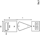
- Fig. 3 shows a schematic diagram of a condition sensor device 36 positioned at a distance d from a passenger face 58.
- the passenger face 58 may have a face width WF and a face height HF. It may furthermore be comprehended from Fig. 3 the forehead width FHW and the forehead height FHH.
- a distance d between the face 58 of vehicle passenger and the condition sensor device 36, particularly the temperature sensor unit 40, may amount to about 500 mm.
- An average face width WF may amount to about 120 mm.
- Fig. 4a to 4c temperature measurements of a face with different face resolutions. That is, Fig. 4a shows a temperature measurement of a person with a face resolution of 30x20 pixels, Fig. 4b shows a temperature measurement of a person with a face resolution of 12x8 pixels, and Fig. 4c shows a temperature measurement of a person with a face resolution of 6x4 pixels. It may be comprehended that the resolution according to Fig. 4a is relatively high and allows an accurate temperature correlation to the body parts of the vehicle passenger, but may require a high cost effort for the temperature sensor unit 40. It may furthermore be comprehended that the resolution according to Fig.
- the resolution according to Fig. 4b is average and still allows a sufficiently accurate temperature correlation to the body parts of the vehicle passenger, particularly considering the count of four pixels for the forehead width FHW. At the same time, such resolution would require only a limited cost effort for the temperature sensor unit 40. Thus, the face resolution of 12x8 pixels may be sufficient for the shown example.
- the minimum pixel density of the temperature sensor unit 40 may be defined by: pixel deg
- a preferable range of pixel per deg may generally be between 0.05 and 10 in horizontal direction.
- a vehicle with a passenger cabin 48 and a condition sensor device 36 with an according resolution may particularly provide sufficiently accurate measurement results, and may at the same time be provided with only limited costs.
Landscapes
- Health & Medical Sciences (AREA)
- Life Sciences & Earth Sciences (AREA)
- Engineering & Computer Science (AREA)
- Physics & Mathematics (AREA)
- Medical Informatics (AREA)
- Public Health (AREA)
- Pathology (AREA)
- Biomedical Technology (AREA)
- General Health & Medical Sciences (AREA)
- Heart & Thoracic Surgery (AREA)
- Molecular Biology (AREA)
- Surgery (AREA)
- Animal Behavior & Ethology (AREA)
- Biophysics (AREA)
- Veterinary Medicine (AREA)
- Psychiatry (AREA)
- Physiology (AREA)
- Pulmonology (AREA)
- Artificial Intelligence (AREA)
- Mechanical Engineering (AREA)
- General Physics & Mathematics (AREA)
- Signal Processing (AREA)
- Computer Vision & Pattern Recognition (AREA)
- Obesity (AREA)
- Developmental Disabilities (AREA)
- Psychology (AREA)
- Social Psychology (AREA)
- Data Mining & Analysis (AREA)
- Epidemiology (AREA)
- Educational Technology (AREA)
- Hospice & Palliative Care (AREA)
- Child & Adolescent Psychology (AREA)
- Databases & Information Systems (AREA)
- Spectroscopy & Molecular Physics (AREA)
- Primary Health Care (AREA)
- Thermal Sciences (AREA)
- Air-Conditioning For Vehicles (AREA)
- Air Conditioning Control Device (AREA)
Description
- The present invention refers to an evaluation system for the condition evaluation of a vehicle passenger, and to a method for evaluating the condition of a vehicle passenger.
- The heating ventilation and air conditioning system (HVAC) of a vehicle has to fulfill certain requirements, like window defrosting, demisting as well as heating and cooling of the passenger cabin. In addition, todays intelligent electronic automatic temperature control systems (EATC) provide a plurality of features, such as cabin air temperature and humidity control, air flow and air distribution management, multizone climate control, sun load compensation, automatic fog detection and/or control of the system towards optimized energy efficiency.
- Passenger comfort is currently assumed at a certain air temperature and associated airflow inside the vehicle cabin, which can be selected and interactively changed by the passenger through the EATC control head. In an auto-mode operation, the passenger may select an interior temperature setting, which is expected to generate a comfortable climate within a certain period of time. The vehicle cabin climate is expected to stay comfortable during the respective trip. Changing parameters during the trip, such as vehicle speed, ambient conditions, sun load, tunnels, or the like must be compensated by the EATC, preferably without any impact to the passenger comfort.
- To reach a comfortable climate inside the passenger cabin under various conditions, high integration effort of the respective sensors and a high number of evaluation drives are required under different ambient conditions and through simulation of expected customer behavior. Such calibration procedure for current EATC systems regarding air flow, air distribution and air temperature control inside the vehicle needs to be done for each vehicle line and each vehicle cabin separately. This requires high efforts and costs.
- Apart from the above, the very indirect way of calibration may still cause passenger discomfort under certain conditions, particularly in case of unsuitable calibration or in case of conditions not considered for calibration.
- It is already known to install infrared sensors in the cabin of vehicle, in order to improve the climate control functionality of HVAC systems. However, such infrared sensors are typically cost intensive. This particularly holds true for infrared sensors with a high resolution. Furthermore, the correlation between infrared measurements and discharge temperatures of a HVAC system may still lead to passenger discomfort under certain conditions.
- It is also known from
US 5674007A to evaluate the condition of a vehicle passenger based on multiple parameters including air temperature, a passenger clothing state, a passenger metabolic rate and a passenger thermal body state. - Against this background it has been the objective of the present invention to provide an evaluation system as well as a method for evaluating the condition of a vehicle passenger, which allow to reduce the risk of passenger discomfort and/or reduce the risk of unsuitable climate conditions within a vehicle.
- The above mentioned objective has been solved by the features of
claims 1 and 14. Preferred embodiments are laid down in the dependent claims, and will be discussed in the following. - An evaluation system according to the present invention is configured for the condition evaluation of a vehicle passenger. Such a condition evaluation may, for example, refer to a comfort condition and/or an emergency condition of a vehicle passenger, but is not limited thereto.
- According to the present invention, the evaluation system comprises a parameter evaluation device being configured to evaluate a plurality of parameters of a set of vehicle interior and vehicle passenger parameters, the set of parameters including:
- a vehicle cabin air temperature parameter,
- a vehicle cabin surface temperature parameter,
- a passenger thermal body state parameter,
- a passenger metabolic rate parameter,
- a passenger clothing level parameter,
- a passenger respiratory rate parameter, and
- a passenger mood state parameter.
- The evaluation system according to the present invention furthermore comprises a condition value evaluation device being configured to evaluate a passenger condition value based on the parameters evaluated by the parameter evaluation unit. The condition value evaluation device is configured to apply a weighting factor for a parameter evaluated by the parameter evaluation device. Said weighting factor is within one of the ranges of:


- a = vehicle cabin air temperature parameter weighting factor,
- b = vehicle cabin surface temperature parameter weighting factor,
- c = passenger thermal body state parameter weighting factor,
- d = passenger metabolic rate parameter weighting factor,
- e = passenger clothing level parameter weighting factor,
- f = passenger respiratory rate parameter weighting factor, and
- g = passenger mood state parameter weighting factor.
- The evaluation system according to the invention is characterized in that
the condition value evaluation device is configured to evaluate a passenger condition value based on the function:
- CV = passenger condition value,
- Tcabin,air,ref = reference vehicle cabin air temperature parameter,
- Tcabin,rad,ref = reference vehicle cabin surface temperature parameter,
- MRref = passenger metabolic rate reference value,
- CLref = passenger clothing level reference value,
- RRref = passenger respiratory rate reference value.
- With an evaluation system according to present invention, a passenger condition value representing detailed condition information may be evaluated. The system allows a flexible and highly individualized condition evaluation, particularly in view of a high number of relevant parameters, while at the same time ensuring their suitable and/or precise consideration for different vehicle functionalities, such as the functionality of an HVAC system, an interior lighting system, an infotainment system, an emergency system and/or other systems of a vehicle. The consideration of a rather high number of detected and/or evaluated parameters widens the data base on a passengers state and/or a vehicle interior state, and subsequently allows to improve the respective functionalities of the vehicle, particularly comfort related functionalities.
- In the present context, the term "passenger" may refer to occupants in general, including, for example, a driver, a co-driver, and/or a rear-passenger.
- According to a preferred embodiment of the present invention, at least one weighting factor for a parameter evaluated by the by the parameter evaluation device may be within the range of


- a = vehicle cabin air temperature parameter weighting factor,
- b = vehicle cabin surface temperature parameter weighting factor,
- c = passenger thermal body state parameter weighting factor,
- d = passenger metabolic rate parameter weighting factor,
- e = passenger clothing level parameter weighting factor,
- f = passenger respiratory rate parameter weighting factor, and
- g = passenger mood state parameter weighting factor.
- According to the invention, the condition value evaluation device is configured to evaluate a passenger comfort condition value, for example a thermal sensation vote. The evaluation system may particularly be suitable for providing a condition value as an input factor for the HVAC system of a vehicle. The passenger comfort may thereby suitably improved. Individual comfort assessment for each passenger, represented by a passenger comfort condition value, for example in the form of a thermal sensation vote, may be used for individual control of discharge temperature, air distribution and/or air velocity of an HVAC system, and therewith improve the comfort of the respective vehicle passenger.
- According to a yet preferred embodiment, the condition value evaluation device may be configured to evaluate a passenger emergency condition value. Such an emergency condition value, for example, representing an health emergency such as a heart attack or cardiac arrest, may be used as an input factor for a vehicle emergency system. The latter may for example be configured for the initiation of an automated emergency call. Passenger safety may therewith be improved.
- According to a yet preferred embodiment, the condition value evaluation device may be configured to provide the evaluated condition value to an electronic automatic temperature control system (EATC) and/or to an infotainment and/or communication system of a vehicle. An EATC system may use the condition value for automated temperature control, and a communication system may use an emergency related condition value for a possible emergency related operation, such as an emergency call. The functionality may therewith be further enhanced.
- According to a yet preferred embodiment, the condition value evaluation device may be configured to evaluate a passenger condition value based on a plurality of remaining parameters evaluated by the parameter evaluation unit in case of any missing parameter and/or any parameter evaluation malfunction. The operational safety of the evaluation system may thereby be improved, particularly avoiding a total malfunction due to the missing of single parameters and/or single parameter evaluation malfunctions.
- According to a yet preferred embodiment, the condition value evaluation device may be configured to apply a predefined substitute parameter value for any missing parameter and/or in case of any parameter evaluation malfunction. That is, in case an intended parameter evaluation is not successful, a predefined substitute parameter value may be applied, in order to avoid significant falsifications of the final condition value. Such predefined substitute parameter value may be saved permanently within the parameter evaluation device and/or within the condition value evaluation device and/or adapted automatically and/or manually.
- According to a yet preferred embodiment, the condition value evaluation device may be configured to apply a weighting factor for each substitute parameter value, said weighting factor corresponding to the weighting factor of the substituted parameter. That is, in case of application of a substitute parameter value, the same weighting factor, which would have been applied for the corresponding parameter, is applied for the substitute parameter value. The risk of falsifications of the final condition value may therewith be further reduced. According to a yet preferred embodiment, the condition value evaluation device may be configured to evaluate a passenger condition value based on at least one predefined parameter reference value, the reference value being within one of the ranges of:


- Tcabin,air,ref = reference vehicle cabin air temperature,
- Tcabin,rad,ref = reference vehicle cabin surface temperature,
- MRref = passenger metabolic rate reference value,
- CLref = passenger clothing level reference value, and
- RRref = passenger respiratory rate reference value.
- By applying such parameter reference values, the evaluation precision may be further improved. The above mentioned parameter reference values may be saved permanently within the parameter evaluation device and/or within the condition value evaluation device. The parameter reference values may be adaptable automatically and/or manually and/or be permanently fixed to a predefined value, particularly unchangeable by a vehicle passenger. According to a yet preferred embodiment, the parameter evaluation device may be configured to evaluate a vehicle cabin air temperature parameter based on at least one temperature measurement of a vehicle interior surface, preferably of a surface with low thermal inertia. Further preferred, the parameter evaluation device may be configured to evaluate a vehicle cabin air temperature parameter based on at least one temperature measurement of a fabric surface and/or a headrest surface and/or a backrest surface and/or a roof lining surface. Such temperature measurement may be conducted with limited effort and high operational safety.
- According to a further preferred embodiment, the parameter evaluation device may be configured to evaluate a vehicle cabin air temperature parameter based on a plurality of temperature measurements of different vehicle interior surfaces. The evaluation accuracy may thereby be improved.
- In a further preferred embodiment, the parameter evaluation device may be configured to evaluate a vehicle cabin air temperature parameter based on the function:


- Tcabin,air = vehicle cabin air temperature parameter,
- Tsurf,i = measured vehicle cabin surface temperature, and
- wi = weighting factor for a vehicle interior surface.
- Evaluations of a vehicle cabin air temperature parameter based on this function may be conducted with only little effort, while at the same time providing sufficiently accurate results.
- According to a further embodiment, the parameter evaluation device may be configured to evaluate a vehicle cabin surface temperature parameter based on at least one temperature measurement of a vehicle interior surface, preferably based on at least one temperature measurement of vehicle cabin surface .
- More preferably, the parameter evaluation device may be configured to evaluate a vehicle cabin surface temperature parameter based on at least one temperature measurement of a dashboard, a ceiling portion, a window portion, and/or a door portion. Such surface portions may have a particularly high thermal inertia, and may therefore provide precise information on the surface temperatures within a vehicle cabin and/or temperature radiation from such surfaces.
- Furthermore, the emissivity coefficient of the respective surface portion may be previously determined and/or suitably predefined and/or permanently saved within the parameter evaluation device and/or within the condition value evaluation device. This allows to accurately assess the respective surface temperature and/or the respective surface temperature parameter. According to a further preferred embodiment, the vehicle cabin surface temperature parameter weighting factor may be based on at least one or a plurality of emissivity values of respective surfaces. The evaluation accuracy may thereby further improved.
- According to a further embodiment, the parameter evaluation device may be configured to evaluate a vehicle cabin surface temperature radiation parameter. That is, any evaluated vehicle cabin surface temperature parameter may be a vehicle cabin surface temperature radiation parameter. Accordingly, the evaluated parameter may represent any possible temperature radiation from cabin surfaces.
- According to a further embodiment, the parameter evaluation device may be configured to evaluate a vehicle cabin surface temperature parameter based on a plurality of temperature measurements of different vehicle interior surfaces. The evaluation accuracy may be further improved and the risk of falsifications by single measurements reduced.
- Particularly preferred, the parameter evaluation device may be configured to evaluate a vehicle cabin surface temperature parameter based on the function:


- Tcabin,rad = vehicle cabin surface temperature parameter,
- Tsurf,i = measured vehicle cabin surface temperature, and
- wi = weighting factor for a vehicle interior surface.
- Evaluations of a surface temperature parameter based on this functions may be conducted with only little effort, while at the same time providing sufficiently accurate results.
- According to a yet further preferred embodiment, the parameter evaluation device may be configured to evaluate a thermal body state parameter, a metabolic rate parameter, a clothing level parameter and/or a respiratory rate parameter based on at least one computer vision algorithm and/or based on at least one measurement of a passenger's head and/or other body parts. Preferably measurements of an arm, a chest and/or a hand of a vehicle passenger may be taken as a basis for the parameter evaluation by the parameter evaluation device. Thereby, detailed information on the condition of a passenger may be acquired with only limited effort. The parameters respectively evaluated may serve for the evaluation of a suitable passenger condition value containing a high level of information.
- According to a yet further preferred embodiment, the parameter evaluation device may be configured to evaluate a thermal body state parameter based on at least one measured skin temperature in a region of interest, preferably of an unclothed body part and/or of a facial, arm and/or hand portion of a vehicle passenger and/or of a body part exposed to solar radiation. This allows a high degree of evaluation accuracy and evaluation safety, while at the same time requiring only limited evaluation effort.
- Further preferred, the parameter evaluation device may be configured to evaluate a local and/or a global thermal body state parameter. A local thermal body state parameter may provide detailed information on single body portions of a vehicle passenger and a global thermal body state may provide detailed information on the overall condition of a vehicle passenger. In case both types of thermal body state parameters may be evaluated, a high degree of evaluation flexibility may be achieved.
- According to a further preferred embodiment, the parameter evaluation device may be configured to evaluate a thermal body state parameter based on a weighted average of skin temperature measurements as well as a temporal gradient of the skin temperature, preferably a temporal gradient of the skin temperature in the facial area of the passenger. Thereby, a global and/or a local thermal body state parameter may be evaluated with only limited effort and at the same time with high accuracy.
- Furthermore, the parameter evaluation device may preferably be configured to evaluate a thermal body state parameter based on the function:


- TBS = passenger thermal body state parameter,
- Tskin,i = measured passenger skin temperature,
- Tskin,ref = passenger skin reference temperature.
- Evaluations of the passenger thermal body state parameter based on this functions may be conducted with only little effort, while at the same time providing sufficiently accurate results.
- According to a further preferred embodiment, the parameter evaluation device may be configured to evaluate a clothing level parameter based on at least one temperature measurement of a local clothing surface in the region of interest of a clothed body part, preferably of a chest and/or arm portion. This allows a simple and effective evaluation of a clothing level parameter.
- Preferably, the parameter evaluation device may be configured to evaluate a clothing level parameter based on the function:

- CL = passenger clothing level parameter,
- Tcabin,air = vehicle cabin air temperature parameter,
- Tbody_surf,i = measured passenger body surface temperature,
and - zi = coefficients.
- The coefficients zi may be derived from empirical correlations and/or predefined on the basis of empirical correlations.
- Preferably, the parameter evaluation device may also be configured to evaluate a clothing level parameter based on the function:

- CL = passenger clothing level parameter,
- Tcabin,air = vehicle cabin air temperature parameter,
- Tbody_surf,i = measured passenger body surface temperature,
and - z1 to z6 = coefficients.
- The coefficients z1 to z6 may be derived from empirical correlations and/or predefined on the basis of empirical correlations.
- The evaluation of the clothing level parameter based on the above function may be conducted with only little effort, while at the same time providing sufficiently accurate results.
- According to a further preferred embodiment, the parameter evaluation device may be configured to evaluate a respiratory rate parameter based on measured temperature fluctuations in the sub-nasal area of the face of a vehicle passenger and/or based on temperature fluctuations caused by alternating airflow through the passenger nose caused by respiratory activity. This allows to reliably evaluate a respiratory rate parameter with only limited effort.
- Further preferred, the parameter evaluation device may be configured to evaluate a respiratory rate parameter using a band pass filter and/or a Fast-Fourier-Transformation. The evaluation accuracy may thereby be further improved and evaluation effort kept limited.
- According to a further preferred embodiment, the parameter evaluation device may be configured to evaluate a metabolic rate parameter based on an evaluated heart beat rate of a vehicle passenger. The heart beat rate may provide a reliable evaluation basis for the metabolic rate parameter.
- Furthermore, the parameter evaluation device may be configured to evaluate a heart beat rate based on measurements and/or monitoring results of a vehicle passenger forehead. A passenger forehead may provide reliable information on the heart beat rate of the respective passenger.
- Preferably, the parameter evaluation device may be configured to evaluate a heart beat rate by measurement of temperature fluctuations caused by the variations in blood flow through the hypodermic blood vessels of a passenger forehead. Such temperature fluctuations may be suitably measured with a framerate of at least 2 fps, more preferably at least 3 fps. The evaluation device may be configured for such framerate measurements.
- The parameter evaluation device may also be configured to evaluate a heart beat rate by measurement of color variations of a vehicle passenger forehead skin, preferably magnified by Eulerian Video Magnification algorithms. Such measurements may be conducted with limited effort and high accuracy.
- Moreover, the parameter evaluation device may be configured to evaluate a metabolic rate parameter using a band pass filter and/or a Fast-Fourier-Transformation. The evaluation accuracy may thereby be further improved and evaluation effort kept limited.
- According to a further preferred embodiment, the parameter evaluation device may be configured to evaluate a mood state parameter based on optical tracking of facial landmarks, preferably eyes, eyebrows, a nose and/or a mouth of a vehicle passenger. Such facial landmarks may provide a reliably information basis for a mood state parameter. For example, an angry or friendly look of a passenger may reliably be evaluated based on optical tracking of such facial landmarks.
- Preferably, the parameter evaluation device may be configured to evaluate a mood state parameter based on a transformation of relative geometric positions of tracked facial landmarks. The evaluation accuracy may thereby be further improved.
- The parameter evaluation device and/or the condition value evaluation device may be provided in the form of a single control device or multiple control devices. Such a control device may comprise a CPU and a data storage device. The data storage device may inter alia comprise suitable programming code, particularly for providing the required functionality of the controller. The parameter evaluation device may comprise a plurality of different parameter evaluation units. Said units may be provided by different portions of a programming code or software portions. It is also possible that the different parameter evaluation units are provided by physically distinct controllers.
- According to a yet further preferred embodiment, the evaluation system may further comprise a condition sensor device, preferably configured for optical and/or temperature measurement. The condition sensor device may comprise at least one optical sensor unit and/or at least one surface temperature sensor unit. Different sensor units may provide different sensing functionalities. By providing an optical sensor unit, certain body portions or cabin surface portions may be detected with limited effort. For these detected portions temperature measurements with surface temperature sensor unit may be conducted. The pixel density of a surface temperature sensor unit may thereby kept small, while at the same time ensuring a sufficient measuring accuracy. Particularly, the combination of the two different units allows the use of a cost-effective temperature sensor unit. The two units may be integrated into one single sensor device or arranged as two separate units. The surface temperature sensor unit may be a longwave infrared sensor unit for surface temperature measurements, such as a pyrometer or infrared temperature sensor. Furthermore, the condition sensor device may be configured to provide sensor signals to the parameter evaluation device.
- According to the present invention, the evaluation system, comprises a parameter evaluation device being configured to evaluate a plurality of parameters of a set of vehicle interior and vehicle passenger parameters, the set of parameters including:
- environmental parameters of a vehicle interior,
- vehicle passenger physiological parameters, and
- at least one vehicle passenger psychological parameter.
- According to the present invention, environmental parameters of a vehicle interior are a vehicle cabin air temperature parameter and a vehicle cabin surface temperature parameter.
- According to the present invention, vehicle passenger physiological parameters are a passenger thermal body state parameter, a passenger metabolic rate parameter, a passenger clothing level parameter, and a passenger respiratory rate parameter
- According to the present invention, a vehicle passenger psychological parameters is a passenger mood state parameter.
- The evaluation system according to the invention further comprises a condition value evaluation device being configured to evaluate a passenger condition value based on at least the parameters evaluated by the parameter evaluation unit.
- According to a further aspect of the present invention, the above described evaluation system may comprise a condition sensor device, wherein the condition sensor device may comprise at least one optical sensor unit for sensing wavelength in the visible spectrum, and at least one temperature sensor unit for sensing wavelengths in the long-wave infrared spectrum, wherein the pixel density of the optical sensor unit is at least 4 times higher, preferably at least 5 times higher, than the pixel density of the temperature sensor unit. The above mentioned difference of pixel densities allows to use a particularly cost-effective temperature sensor unit, while at the same time ensuring sufficiently high resolutions by additionally using optical sensor unit with a significant higher pixel density. Optical sensor units may still be provided at low costs even in case of relatively high pixel densities.
- In the present context, the term pixel density may be understood as the relation between the field of view and the number of pixels.
- Furthermore, the long-wave infrared spectrum comprises wavelengths between 7 µm and 15 µm, particularly between 8 µm and 14 µm. Accordingly, long-wave infrared radiation may refer to a radiated heat, preferably - but not limited to - a wavelength of 8 µm to 14 µm.
- According to a further aspect of the present invention the minimum pixel density of the temperature sensor unit may be defined by the function:

- d = distance between the temperature sensor and a passenger face,
- HP = minimum number of horizontal pixels for a face resolution, and
- WF = average width of a passenger face.
- Alternatively, the minimum pixel density of the temperature sensor unit may be defined by the function:

- d = distance between the temperature sensor and a passenger face,
- VP = minimum number of vertical pixels for a face resolution, and
- HF = average height of a passenger face.
- Furthermore, in the present context a preferable range of pixel per deg may be between 0.05 and 10 in horizontal direction.
- Furthermore, in the present context a preferable range of pixel per deg may be between 0.05 and 10 in vertical direction.
- A further aspect of the present invention refers to a method for evaluating the condition of a vehicle passenger with an above described evaluation system, the method comprising the steps of:
- evaluating a plurality of parameters of a set of vehicle interior and vehicle passenger parameters, the set of parameters including:
- a vehicle cabin air temperature parameter,
- a vehicle cabin surface temperature parameter,
- a passenger thermal body state parameter,
- a passenger metabolic rate parameter,
- a passenger clothing level parameter,
- a passenger respiratory rate parameter, and
- a passenger mood state parameter; and
- evaluating a passenger condition value based on at least the plurality of evaluated parameters;
- wherein the evaluation of the condition value is conducted by applying a weighting factor for an evaluated parameter; the weighting factor being within one of the ranges of:


- a = vehicle cabin air temperature parameter weighting factor,
- b = vehicle cabin surface temperature parameter weighting factor,
- c = passenger thermal body state parameter weighting factor,
- d = passenger metabolic rate parameter weighting factor,
- e = passenger clothing level parameter weighting factor,
- f = passenger respiratory rate parameter weighting factor, and
- g = passenger mood state parameter weighting factor.
- The method according to the invention is characterized in that a passenger condition value (CV) is evaluated based on the function:

- CV = passenger condition value,
- Tcabin,air,ref = reference vehicle cabin air temperature parameter,
- Tcabin,rad,ref = reference vehicle cabin surface temperature parameter,
- MRref = passenger metabolic rate reference value,
- CLref = passenger clothing level reference value,
- RRref = passenger respiratory rate reference value.
- According to a preferred embodiment, the evaluation of the condition value is conducted by applying at least one weighting factor within the range of:


- a = vehicle cabin air temperature parameter weighting factor,
- b = vehicle cabin surface temperature parameter weighting factor,
- c = passenger thermal body state parameter weighting factor,
- d = passenger metabolic rate parameter weighting factor,
- e = passenger clothing level parameter weighting factor,
- f = passenger respiratory rate parameter weighting factor, and
- g = passenger mood state parameter weighting factor.
- The above explanations and details regarding the evaluation system apply also to the method for evaluating the condition of a vehicle passenger.
- Other embodiments of the invention result from combinations of the features disclosed in the claims, the specification and the drawings.
- Fig. 1
- is a schematic diagram of an evaluation device according to an embodiment of the present invention,
- Fig. 2
- is a schematic diagram of a condition sensor device arranged within a passenger cabin of a vehicle,
- Fig. 3
- is a schematic diagram of a condition sensor device positioned at a distance from a passenger face,
- Fig. 4a
- shows a temperature measurement of a person with a face resolution of 30x20 pixels,
- Fig. 4b
- shows a temperature measurement of a person with a face resolution of 12x8 pixels,
- Fig. 4c
- shows a temperature measurement of a person with a face resolution of 6x4 pixels.
-
Fig. 1 is a schematic diagram of anevaluation device 10 according to an embodiment of the present invention. Theevaluation device 10 shown inFig. 1 is configured for the condition evaluation of a vehicle passenger. Such condition evaluation of a vehicle passenger may include the evaluation of a passenger comfort condition value, preferably a thermal sensation vote, and/or a passenger emergency condition value. - The
evaluation device 10 shown inFig. 1 comprises aparameter evaluation device 12 being configured to evaluate a plurality of parameters of a set of vehicle interior and vehicle passenger parameters. The set of parameters includes a vehicle cabin air temperature parameter, a vehicle cabin surface temperature parameter, a passenger thermal body state parameter, a passenger metabolic rate parameter, a passenger clothing level parameter, a passenger respiratory rate parameter, and a passenger mood state parameter. The set of parameters may also include passenger heart beat rate parameter. - For the evaluation of the above mentioned parameters, the
parameter evaluation device 12 may comprise a vehicle cabin air temperatureparameter evaluation unit 14, a vehicle cabin surface temperatureparameter evaluation unit 16, a passenger thermal body stateparameter evaluation unit 18, a passenger metabolic rateparameter evaluation unit 20, a passenger clothing levelparameter evaluation unit 22, a passenger respiratory rateparameter evaluation unit 24, and/or a passenger mood stateparameter evaluation unit 26. Theparameter evaluation device 12 may also comprise a heart beatrate evaluation unit 28. - Furthermore, the
evaluation device 10 according to the embodiment inFig. 1 comprises a conditionvalue evaluation device 30 being configured to evaluate a passenger condition value based on at least the parameters evaluated by theparameter evaluation unit 12. The conditionvalue evaluation device 30 is configured to evaluate a passenger comfort condition value, preferably a thermal sensation vote, and/or a passenger emergency condition value. - The condition
value evaluation device 30 is configured to apply a weighting factor for a parameter evaluated by theparameter evaluation device 12, the weighting factor being within one of the ranges of:


- a = vehicle cabin air temperature parameter weighting factor,
- b = vehicle cabin surface temperature parameter weighting factor,
- c = passenger thermal body state parameter weighting factor,
- d = passenger metabolic rate parameter weighting factor,
- e = passenger clothing level parameter weighting factor,
- f = passenger respiratory rate parameter weighting factor, and
- g = passenger mood state parameter weighting factor.
- The consideration of the different parameters allows an holistic evaluation of a passenger condition. At the same time, the above weighting factors may ensure that the parameters are put in a suitable and/or realistic relation to each other, in order for the final condition value to be accurate and suitable for any further control operation.
- Furthermore, the condition
value evaluation device 30 may be configured to evaluate a passenger condition value CV based on at least one predefined parameter reference value, the reference value being within one of the ranges of:


- Tcabin,air,ref = reference vehicle cabin air temperature,
- Tcabin,rad,ref = reference vehicle cabin surface temperature,
- MRref = passenger metabolic rate reference value,
- CLref = passenger clothing level reference value, and
- RRref = passenger respiratory rate reference value.
- The condition
value evaluation device 30 is configured to evaluate a passenger condition value CV based on the function:
- CV = passenger condition value,
- Tcabin,air = vehicle cabin air temperature parameter,
- Tcabin,air,ref = reference vehicle cabin air temperature parameter,
- Tcabin,rad = vehicle cabin surface temperature parameter,
- Tcabin,rad,ref = reference vehicle cabin surface temperature parameter,
- TBS = passenger thermal body state parameter,
- MR = passenger metabolic rate parameter,
- MRref = passenger metabolic rate reference value,
- CL = passenger clothing level parameter,
- CLref = passenger clothing level reference value,
- RR = passenger respiratory rate parameter,
- RRref = passenger respiratory rate reference value, and
- MS = passenger mood state parameter;
and where- a = vehicle cabin air temperature parameter weighting factor,
- b = vehicle cabin surface temperature parameter weighting factor,
- c = passenger thermal body state parameter weighting factor,
- d = passenger metabolic rate parameter weighting factor,
- e = passenger clothing level parameter weighting factor,
- f = passenger respiratory rate parameter weighting factor, and
- g = passenger mood state parameter weighting factor.
- The condition value evaluated by the condition
value evaluation device 30 may be provided to atransformation unit 32 for transforming the condition value to an equivalent set temperature or discharge temperature and air distribution setting. Such data from thetransformation unit 32 may be used as an input signal for anHVAC control system 34. Alternatively, the condition value evaluated by the conditionvalue evaluation device 30 can be used as an input signal for the cabin air temperature of the vehicle. - The
evaluation device 10 may further comprise acondition sensor device 36 for providing measurement data and/or measurement signals to at least one of theparameter evaluation units 14 to 28. Thecondition sensor device 36 may comprise at least oneoptical sensor unit 38 for sensing wavelengths in the visible spectrum, and at least onetemperature sensor unit 40 for sensing wavelengths in the long-wave infrared spectrum. Theoptical sensor unit 38 may also be configured for sensing wavelengths in the near infrared spectrum. Theoptical sensor unit 38 may be equipped with an infrared light source for night vision abilities. Thetemperature sensor unit 40 may be configured for detecting infrared equivalent blackbody radiation, particularly blackbody radiation around 300 Kelvin. - The pixel density of the
optical sensor unit 38 may be at least 4 times higher, preferably at least 5 times higher, than the pixel density of thetemperature sensor unit 40. Therewith, thecondition sensor device 36 may provide measurement results in sufficient accuracy. At the same time suchcondition sensor device 36 may be produced with only limited costs, particularly due to the comparatively low pixel density of thetemperature sensor unit 40. That is, the resolution provided by theoptical sensor unit 38 is much higher than the resolution of thetemperature sensor unit 40. Combining the information provided from the twosensor units temperature sensor unit 40. - As mentioned above, the
condition sensor device 36 may provide measurement data and/or measurement signals to at least one of theparameter evaluation units 14 to 28. The differentparameter evaluation units 14 to 28 may therefore be configured to evaluate parameters on the basis of specific input data and/or input signals provided by thecondition sensor device 36. - The vehicle cabin air temperature
parameter evaluation unit 14 may be configured to evaluate a vehicle cabin air temperature parameter Tcabin,air based on a measured vehicle cabin surface temperature Tsurf,i. The measured vehicle cabin surface temperature Tsurf,i may be provided by thecondition sensor device 36. The vehicle cabin air temperatureparameter evaluation unit 14 may particularly be configured to evaluate a vehicle cabin air temperature parameter Tcabin,air based on a plurality of temperature measurements Tsurf,i of different vehicle interior surfaces. - The evaluation of the vehicle cabin air temperature parameter Tcabin,air by the vehicle cabin air temperature
parameter evaluation unit 14 may be based on the function:


- Tcabin,air = vehicle cabin air temperature parameter,
- Tsurf,i = measured vehicle cabin surface temperature, and
- wi = weighting factor for a vehicle interior surface.
- The vehicle cabin surface temperature
parameter evaluation unit 16 may be configured to evaluate a vehicle cabin surface temperature parameter Tcabin,rad based on at least one measured vehicle cabin surface temperature Tsurf,i. The measured vehicle cabin surface temperature Tsurf,i may be provided by thecondition sensor device 36. The vehicle cabin surface temperatureparameter evaluation unit 16 may particularly be configured to evaluate a vehicle cabin surface temperature parameter Tcabin,rad based on a plurality of temperature measurements Tsurf,i of different vehicle interior surfaces, such as a dashboard, a ceiling portion, a window portion, and/or a door portion. The vehicle cabin surface temperature parameter Tcabin,rad may, for example, be and/or represent a solar and/or radiant flux parameter. - The evaluation of the vehicle cabin surface temperature parameter Tcabin,rad by the vehicle cabin surface temperature
parameter evaluation unit 16 may be based on the function:


- Tcabin,rad = vehicle cabin surface temperature parameter,
- Tsurf,i = measured vehicle cabin surface temperature, and
- wi = weighting factor for a vehicle interior surface.
- The thermal body state
parameter evaluation unit 18 may be configured to evaluate a thermal body state parameter TBS based on at least one measured skin temperature Tskin,i. The measured skin temperature Tskin,i may be provided by thecondition sensor device 36. In particular, the thermal body stateparameter evaluation unit 18 may be configured to evaluate a thermal body state parameter TBS based on a weighted average of skin temperature measurements Tskin,i as well as a temporal gradient dTskin,i of the skin temperature, preferably a temporal gradient of the skin temperature in the facial area of the passenger. - The thermal body state
parameter evaluation unit 18 may be configured to evaluate a thermal body state parameter TBS based on the function:


- TBS = passenger thermal body state parameter,
- Tskin,i = measured passenger skin temperature,
- Tskin,ref = passenger skin reference temperature.
- The metabolic rate
parameter evaluation unit 20 may be configured to evaluate a metabolic rate parameter MR based on an evaluated heart beat rate HR or heart beat rate parameter HR. For evaluating a heart beat rate HR or heart beat rate parameter HR, theparameter evaluating device 12 may comprise the heart beat rateparameter evaluation unit 28. The heart beat rateparameter evaluation unit 28 may be configured for providing an evaluated heart beat rate HR or heart beat rate parameter HR to the metabolic rateparameter evaluation unit 20. - The heart beat rate
parameter evaluation unit 28 may be configured to evaluate a heart beat rate HR and/or heart beat rate parameter HR based on measurements 42 and/or monitoring results 44 of a vehicle passenger forehead, preferably by measurement of temperature fluctuations caused by the variations in blood flow through the hypodermic blood vessels and/or by measurements of color variations of a vehicle passenger forehead skin. The vehicle passenger forehead measurements 42 and/or monitoring results 44 may be provided by thecondition sensor device 36. Measurements 42 and/or monitoring results 44 may also be provided by wearable devices. Such wearable devices may, for example, be smartwatches, wearable heart beat rate measuring devices, wearable electrocardiography devices, pulse oximetry devices, and/or devices for the measurement of oxygen saturation. - The clothing level
parameter evaluation unit 22 may be configured to evaluate a clothing level parameter CL based on at least one measured passenger body surface temperature Tbody_surf,i, particularly a temperature measurement of a local clothing surface in the region of interest of a clothed body part, preferably of a chest and/or arm portion. The clothing levelparameter evaluation unit 22 may also be configured to evaluate a clothing level parameter CL based on at least one measured skin temperature Tskin,i and/or at least one measured cabin air temperature Tcabin,air. The measured passenger body surface temperature Tbody_surf,i, the measured skin temperature Tskin,i and/or the at least one measured cabin air temperature Tcabin,air may be provided by thecondition sensor device 36. - The clothing level
parameter evaluation unit 22 may be configured to evaluate a clothing level parameter (CL) based on the function:
- CL = passenger clothing level parameter,
- Tcabin,air = vehicle cabin air temperature parameter,
- Tbody_surf,i = measured passenger body surface temperature,
and - z1 to z6 = coefficients.
- The respiratory rate
parameter evaluating unit 24 may be configured to evaluate a respiratory rate parameter RR based on measuredtemperature fluctuations 46 in the sub-nasal area of the face of a vehicle passenger and/or based ontemperature fluctuations 46 caused by alternating airflow through the passenger nose caused by respiratory activity. The measuredtemperature fluctuations 46 may be provided by thecondition sensor device 36. - The mood state
parameter evaluation unit 26 may be configured to evaluate a mood state parameter MS based on optical tracking VIS of facial landmarks, preferably eyes, eyebrows, nose and/or mouth of a vehicle passenger, and/or based on a transformation of relative geometric positions of tracked facial landmarks. The input data and/or signals for the mood stateparameter evaluation unit 26 may be provided by thecondition sensor device 36. - The
parameter evaluation device 12 and/or the conditionvalue evaluation device 30 may be provided in the form of a single control device or multiple control devices. Such a control device may comprise a CPU and a data storage device. The data storage may comprise suitable programming code, particularly for providing the required functionality of the controller. The differentparameter evaluation units 14 to 28 may be provided by different portions of a programming code or software portions. It is also possible that the differentparameter evaluation units 14 to 28 are provided by physically distinct controllers. -
Fig. 2 shows a schematic diagram of acondition sensor device 36 arranged within apassenger cabin 48 of a vehicle. Thecondition sensor device 36 may, for example, be arranged at or adjacent to arearview mirror 50. Accordingly, both theoptical sensor unit 38 for sensing wavelengths in the visible spectrum, and thetemperature sensor unit 40 for sensing wavelengths in the long-wave infrared spectrum may be arranged at the same place within thepassenger cabin 48 or at least directly adjacent to each other. It is possible that the twosensor units different sensor units sensor units parameter evaluation device 12. - As may be comprehended from
Fig. 2 , thecondition sensor device 36 may have a field of view FoV, which covers at least adriver seat 52 and or aco-driver seat 54. The sensor field of view FoV may also cover rear seats of thepassenger cabin 48, which are not shown here. Apartial view angle 56 of the field of view FoV may cover a driver head position. - The resulting pixel density of an object to be optically sensed by the
condition sensor device 36 is dependent on several factors, such as the sensor resolution, the field of view FoV, as well as the position of thecondition sensor device 36 relative to the object to be sensed, for example, the head and/or face of a vehicle passenger. - The
condition sensor device 36 may have minimal requirements in terms of required pixel densities for the optical sensor unit 38 (visible domain) and for the temperature sensor unit 40 (thermal domain) to be applied for a specific configuration inside a vehicle cabin. Thecondition sensor device 36 may particularly require a resolution high enough in the visible domain via theoptical sensor unit 38 to reliably identify and/or track different parts of the body of a vehicle passenger, particularly the face including the forehead and/or other regions of the face, such as the nose, the cheeks, the temples, the chin and/or the jaw. A minimum pixel density of the temperature sensor unit 40 (thermal domain) may be required to accurately correlate temperatures to the body parts of the vehicle passenger, such as different parts of the face, to the identified regions. - As mentioned above, the pixel density of the
optical sensor unit 38 may at least be 4 times higher, preferably at least 5 times higher, than the pixel density of thetemperature sensor unit 40. Furthermore, the minimum pixel density of thetemperature sensor unit 40 may be defined by the function:
- d = distance between the temperature sensor and a passenger face,
- HP = minimum number of horizontal pixels for a face resolution, and
- WF = average width of a passenger face.
-
Fig. 3 shows a schematic diagram of acondition sensor device 36 positioned at a distance d from apassenger face 58. Thepassenger face 58 may have a face width WF and a face height HF. It may furthermore be comprehended fromFig. 3 the forehead width FHW and the forehead height FHH. - Depending on the design of the
respective passenger cabin 48, a distance d between theface 58 of vehicle passenger and thecondition sensor device 36, particularly thetemperature sensor unit 40, may amount to about 500 mm. An average face width WF may amount to about 120 mm. -
Fig. 4a to 4c temperature measurements of a face with different face resolutions. That is,Fig. 4a shows a temperature measurement of a person with a face resolution of 30x20 pixels,Fig. 4b shows a temperature measurement of a person with a face resolution of 12x8 pixels, andFig. 4c shows a temperature measurement of a person with a face resolution of 6x4 pixels. It may be comprehended that the resolution according toFig. 4a is relatively high and allows an accurate temperature correlation to the body parts of the vehicle passenger, but may require a high cost effort for thetemperature sensor unit 40. It may furthermore be comprehended that the resolution according toFig. 4c is relatively low and would not allow any accurate temperature correlation to the body parts of the vehicle passenger, particularly considering the count of only two pixels for the forehead width FHW. Finally, it may be comprehended that the resolution according toFig. 4b is average and still allows a sufficiently accurate temperature correlation to the body parts of the vehicle passenger, particularly considering the count of four pixels for the forehead width FHW. At the same time, such resolution would require only a limited cost effort for thetemperature sensor unit 40. Thus, the face resolution of 12x8 pixels may be sufficient for the shown example. - Following the above, the minimum pixel density of the
temperature sensor unit 40 may be defined by:
- 500 mm = distance between the temperature sensor and a passenger face,
- 8 = minimum number of horizontal pixels for a face resolution, and
- 120 mm = average width of a passenger face.
- In addition to the calculation example above, a preferable range of pixel per deg may generally be between 0.05 and 10 in horizontal direction.
- A vehicle with a
passenger cabin 48 and acondition sensor device 36 with an according resolution may particularly provide sufficiently accurate measurement results, and may at the same time be provided with only limited costs.
Claims (14)
- Evaluation system (10) for the condition evaluation of a vehicle passenger, the system comprising:- a parameter evaluation device (12) being configured to evaluate a plurality of parameters of a set of vehicle interior and vehicle passenger parameters, the set of parameters including:- a vehicle cabin air temperature parameter (Tcabin,air),- a vehicle cabin surface temperature parameter (Tcabin,rad),- a passenger thermal body state parameter (TBS),- a passenger metabolic rate parameter (MR),- a passenger clothing level parameter (CL),- a passenger respiratory rate parameter (RR), and- a passenger mood state parameter (MS); and- a condition value evaluation device (30) being configured to evaluate a passenger condition value (CV) based on the parameters evaluated by the parameter evaluation unit (12);- wherein the condition value evaluation device (30) is configured to apply a weighting factor for a parameter evaluated by the parameter evaluation device (12); the weighting factor being within one of the ranges of:where:


 a = vehicle cabin air temperature parameter weighting factor,b = vehicle cabin surface temperature parameter weighting factor,c = passenger thermal body state parameter weighting factor,d = passenger metabolic rate parameter weighting factor,e = passenger clothing level parameter weighting factor,f = passenger respiratory rate parameter weighting factor, andg = passenger mood state parameter weighting factorcharacterized in that the condition value evaluation device (30) is configured to evaluate a passenger condition value (CV) based on the function:
 CV = passenger condition value,Tcabin,air,ref = reference vehicle cabin air temperature parameter,Tcabin,rad,ref = reference vehicle cabin surface temperature parameter,MRref = passenger metabolic rate reference value,CLref = passenger clothing level reference value,RRref = passenger respiratory rate reference value.
 - Evaluation system (10) according to claim 1, wherein the condition value evaluation device (30) is configured to provide the evaluated condition value to a heating ventilation and air conditioning system (HVAC) and/or to an electronic automatic temperature control system (EATC) and/or to an infotainment and/or communication system of a vehicle.
- Evaluation system (10) according to claim 1 or 2, wherein the condition value evaluation device (30) is configured to evaluate a passenger condition value (CV) based on a plurality of remaining parameters evaluated by the parameter evaluation unit in case of any missing parameter or any parameter evaluation malfunction and wherein the condition value evaluation device (30) is configured to apply a predefined substitute parameter value for any missing parameter or in case of any parameter evaluation malfunction and wherein the condition value evaluation device (30) is configured to apply a weighting factor for each substitute parameter value, said weighting factor corresponding to the weighting factor of the substituted parameter.
- Evaluation system (10) according to any one of the preceding claims, wherein the condition value evaluation device (30) is configured to evaluate a passenger condition value (CV) based on at least one predefined parameter reference value, the reference value being within one of the ranges of:


 Tcabin,air,ref = reference vehicle cabin air temperature,Tcabin,rad,ref = reference vehicle cabin surface temperature,MRref = passenger metabolic rate reference value,CLref = passenger clothing level reference value, andRRref = passenger respiratory rate reference value.
 - Evaluation system (10) according to any one of the preceding claims, wherein the parameter evaluation device (12) is configured to evaluate a thermal body state parameter (TBS), a metabolic rate parameter (MR), a clothing level parameter (CL) and/or a respiratory rate parameter (RR) based on at least one computer vision algorithm and/or based on at least one measurement of a passenger's head and/or other body parts, preferably an arm, chest and/or a hand.
- Evaluation system (10) according to any one of the preceding claims, wherein the parameter evaluation device (12) is configured to evaluate a thermal body state parameter (TBS) based on at least one measured skin temperature in a region of interest, preferably of an unclothed body part and/or of a facial, arm and/or hand portion of a vehicle passenger and/or of a body part exposed to solar radiation, and/or wherein the parameter evaluation device is configured to evaluate a local and/or a global thermal body state parameter.
- Evaluation system (10) according to any one of the preceding claims, wherein the parameter evaluation device (12) is configured to evaluate a thermal body state parameter (TBS) based on a weighted average of skin temperature measurements as well as a temporal gradient of the skin temperature, preferably a temporal gradient of the skin temperature in the facial area of the passenger, and/or wherein the parameter evaluation device (12) is configured to evaluate a thermal body state parameter (TBS) based on the function:


 TBS = passenger thermal body state parameter,Tskin,i = measured passenger skin temperature,Tskin,ref = passenger skin reference temperature.
 - Evaluation system (10) according to any one of the preceding claims, wherein the parameter evaluation device (12) is configured to evaluate a clothing level parameter (CL) based on at least one temperature measurement of a local clothing surface in the region of interest of a clothed body part, preferably of a chest and/or arm portion, and/or wherein the parameter evaluation device (12) is configured to evaluate a clothing level parameter (CL) based on the function:

 CL = passenger clothing level parameter,Tcabin,air = vehicle cabin air temperature parameter,Tbody_surf,i = measured passenger body surface temperature,
andzi; z1 to z6 = coefficients. - Evaluation system (10) according to any one of the preceding claims, wherein the parameter evaluation device (12) is configured to evaluate a respiratory rate parameter (RR) based on measured temperature fluctuations in the sub-nasal area of the face of a vehicle passenger and/or based on temperature fluctuations caused by alternating airflow through the passenger nose caused by respiratory activity and/or wherein the parameter evaluation device (12) is configured to evaluate a respiratory rate parameter (RR) using a band pass filter and/or a Fast-Fourier-Transformation.
- Evaluation system (10) according to any one of the preceding claims, wherein the parameter evaluation device (12) is configured to evaluate a metabolic rate parameter (MR) based on an evaluated heart beat rate and/or heart beat rate parameter (HR) and/or wherein the parameter evaluation device (12) is configured to evaluate a heart beat rate (HR) and/or heart beat rate parameter (HR) based on measurements and/or monitoring results of a vehicle passenger forehead, preferably by measurement of temperature fluctuations caused by the variations in blood flow through the hypodermic blood vessels and/or by measurements with a framerate of at least 2 fps, more preferably at least 3 fps, and/or by measurements of color variations of a vehicle passenger forehead skin, preferably magnified by Eulerian Video Magnification algorithms, and/or the parameter evaluation device is configured to evaluate a metabolic rate parameter (MR) using a band pass filter and/or a Fast-Fourier- Transformation.
- Evaluation system (10) according to any one of the preceding claims, wherein the parameter evaluation device (12) is configured to evaluate a mood state parameter (MS) based on optical tracking of facial landmarks, preferably eyes, eyebrows, nose and/or mouth of a vehicle passenger, and/or based on a transformation of relative geometric positions of tracked facial landmarks.
- Evaluation system (10) according any one of the preceding claims 1 to 11, comprising a condition sensor device (36), the condition sensor device (36) comprising:- at least one optical sensor unit (38) for sensing wavelength in the visible spectrum, and- at least one temperature sensor unit (40) for sensing wavelengths in the long-wave infrared spectrum,- wherein the pixel density of the optical sensor unit (38) is higher than the pixel density of the temperature sensor unit (40).
- Evaluation system (10) according to claim 12, wherein the minimum pixel density of the temperature sensor unit (40) is defined by the function:
 d = distance between the temperature sensor and a passenger face,HP = minimum number of horizontal pixels for a face resolution, andWF = average width of a passenger face.
 - Method for evaluating the condition of a vehicle passenger with an evaluation system (10) according to any one of claims 1 to 13 the method comprising the steps of:- evaluating a plurality of parameters of a set of vehicle interior and/or vehicle passenger parameters, the set of parameters including:- a vehicle cabin air temperature parameter (Tcabin,air),- a vehicle cabin surface temperature parameter (Tcabin,rad),- a passenger thermal body state parameter (TBS),- a passenger metabolic rate parameter (MR),- a passenger clothing level parameter (CL),- a passenger respiratory rate parameter (RR), and- a passenger mood state parameter (MS); and- evaluating a passenger condition value (CV) based on the plurality of evaluated parameters;- wherein the evaluation of the condition value (CV) is conducted by applying a weighting factor for an evaluated parameter; the weighting factor being within one of the ranges of:where:


 a = vehicle cabin air temperature parameter weighting factor,b = vehicle cabin surface temperature parameter weighting factor,c = passenger thermal body state parameter weighting factor,d = passenger metabolic rate parameter weighting factor,e = passenger clothing level parameter weighting factor,f = passenger respiratory rate parameter weighting factor, andg = passenger mood state parameter weighting factorcharacterized in that a passenger condition value (CV) is evaluated based on the function:
 CV = passenger condition value,Tcabin,air,ref = reference vehicle cabin air temperature parameter,Tcabin,rad,ref = reference vehicle cabin surface temperature parameter,MRref = passenger metabolic rate reference value,CLref = passenger clothing level reference value,RRref = passenger respiratory rate reference value.
Priority Applications (2)
| Application Number | Priority Date | Filing Date | Title |
|---|---|---|---|
| EP19167631.1A EP3718796B1 (en) | 2019-04-05 | 2019-04-05 | Evaluation system for the condition evaluation of a passenger |
| CN202010265630.7A CN111789573A (en) | 2019-04-05 | 2020-04-07 | Evaluation system and condition sensor device |
Applications Claiming Priority (1)
| Application Number | Priority Date | Filing Date | Title |
|---|---|---|---|
| EP19167631.1A EP3718796B1 (en) | 2019-04-05 | 2019-04-05 | Evaluation system for the condition evaluation of a passenger |
Publications (2)
| Publication Number | Publication Date |
|---|---|
| EP3718796A1 EP3718796A1 (en) | 2020-10-07 |
| EP3718796B1 true EP3718796B1 (en) | 2022-11-23 |
Family
ID=66101980
Family Applications (1)
| Application Number | Title | Priority Date | Filing Date |
|---|---|---|---|
| EP19167631.1A Active EP3718796B1 (en) | 2019-04-05 | 2019-04-05 | Evaluation system for the condition evaluation of a passenger |
Country Status (2)
| Country | Link |
|---|---|
| EP (1) | EP3718796B1 (en) |
| CN (1) | CN111789573A (en) |
Families Citing this family (2)
| Publication number | Priority date | Publication date | Assignee | Title |
|---|---|---|---|---|
| CN112721571B (en) * | 2021-02-03 | 2023-05-09 | 重庆桴之科科技发展有限公司 | Multi-parameter-affected shared automobile rear-row microclimate adjusting method and system |
| CN113242408B (en) * | 2021-04-26 | 2023-04-07 | 西安建筑科技大学 | Building site safety monitoring system based on computer vision technology |
Family Cites Families (6)
| Publication number | Priority date | Publication date | Assignee | Title |
|---|---|---|---|---|
| JP3055923B2 (en) * | 1990-08-24 | 2000-06-26 | 株式会社豊田中央研究所 | Control device for air conditioner |
| KR0133482B1 (en) * | 1994-03-09 | 1998-05-15 | 구자홍 | Pmv calculating method |
| DE112013005660T5 (en) * | 2012-11-27 | 2015-08-20 | Faurecia Automotive Seating, Llc | Vehicle seat with integrated sensors |
| WO2016052795A1 (en) * | 2014-09-30 | 2016-04-07 | 주식회사 티노스 | Air conditioning device for vehicle and method for controlling same |
| US10486490B2 (en) * | 2015-04-16 | 2019-11-26 | Panasonic intellectual property Management co., Ltd | Air-conditioning control device |
| FR3065915B1 (en) * | 2017-05-03 | 2020-07-24 | Valeo Systemes Thermiques | THERMAL MANAGEMENT SYSTEM FOR A MOTOR VEHICLE INTERIOR |
-
2019
- 2019-04-05 EP EP19167631.1A patent/EP3718796B1/en active Active
-
2020
- 2020-04-07 CN CN202010265630.7A patent/CN111789573A/en active Pending
Also Published As
| Publication number | Publication date |
|---|---|
| CN111789573A (en) | 2020-10-20 |
| EP3718796A1 (en) | 2020-10-07 |
Similar Documents
| Publication | Publication Date | Title |
|---|---|---|
| CN111981655B (en) | Sensing system | |
| CN213501729U (en) | Thermal management system for a motor vehicle passenger compartment | |
| JP2008302924A (en) | Control system provided with sensor of physiological data for air conditioning facility of automobile | |
| EP3718796B1 (en) | Evaluation system for the condition evaluation of a passenger | |
| EP2720607B1 (en) | Method and device for detecting thermal comfort | |
| US10926773B2 (en) | Systems and methods for mitigating motion sickness in a vehicle | |
| US20210394584A1 (en) | Heat control method for a heat control device, particularly for a vehicle interior | |
| JP4409954B2 (en) | Head position sensor | |
| CN112097916B (en) | Medical epidemic prevention temperature measurement system and method | |
| ES2368531T3 (en) | DEVICE FOR THE ADJUSTMENT OF OPERATING PARAMETERS ASSOCIATED WITH INDIVIDUAL AREAS OF A PASSENGER COMPARTMENT OF A VEHICLE, IN PARTICULAR OF A VEHICLE CLIMATE INSTALLATION SYSTEM. | |
| JP2022506837A (en) | Thermal management system for the passenger compartment of a car | |
| CN111317452A (en) | Automatic method for rapidly detecting body temperature of person in passenger car | |
| KR20210077777A (en) | Thermal management system for automotive passenger compartment | |
| JP2011123653A (en) | Test device for driver's arousal level | |
| EP3718797A1 (en) | Mass transportation vehicle with passenger detection | |
| US11279204B2 (en) | Vehicle and method for controlling the same | |
| US20060023918A1 (en) | Method for determining the current position of the heads of vehicle occupants | |
| JPH10197348A (en) | Method for processing thermal image | |
| CN110664381A (en) | Method and device for monitoring the capacity of a crew of an aircraft | |
| WO2020119687A1 (en) | A system and method for estimating climate needs | |
| WO2020094981A1 (en) | Thermal management system for a motor vehicle passenger compartment | |
| JP2004314887A (en) | Air-conditioner for vehicle | |
| IT202000002665A1 (en) | METHOD OF CONTROL OF AN AIR CONDITIONING SYSTEM IN A COCKPIT OF A ROAD VEHICLE | |
| CN111587366A (en) | Device for analyzing infrared radiation from the surface of the passenger compartment of a motor vehicle | |
| US20110285997A1 (en) | Assembly And Method for Evaluating Effectiveness of Anti-Fog Coatings of Eyewear Lenses |
Legal Events
| Date | Code | Title | Description |
|---|---|---|---|
| PUAI | Public reference made under article 153(3) epc to a published international application that has entered the european phase |
Free format text: ORIGINAL CODE: 0009012 |
|
| STAA | Information on the status of an ep patent application or granted ep patent |
Free format text: STATUS: THE APPLICATION HAS BEEN PUBLISHED |
|
| AK | Designated contracting states |
Kind code of ref document: A1 Designated state(s): AL AT BE BG CH CY CZ DE DK EE ES FI FR GB GR HR HU IE IS IT LI LT LU LV MC MK MT NL NO PL PT RO RS SE SI SK SM TR |
|
| AX | Request for extension of the european patent |
Extension state: BA ME |
|
| STAA | Information on the status of an ep patent application or granted ep patent |
Free format text: STATUS: REQUEST FOR EXAMINATION WAS MADE |
|
| 17P | Request for examination filed |
Effective date: 20210407 |
|
| RBV | Designated contracting states (corrected) |
Designated state(s): AL AT BE BG CH CY CZ DE DK EE ES FI FR GB GR HR HU IE IS IT LI LT LU LV MC MK MT NL NO PL PT RO RS SE SI SK SM TR |
|
| STAA | Information on the status of an ep patent application or granted ep patent |
Free format text: STATUS: EXAMINATION IS IN PROGRESS |
|
| 17Q | First examination report despatched |
Effective date: 20210902 |
|
| GRAP | Despatch of communication of intention to grant a patent |
Free format text: ORIGINAL CODE: EPIDOSNIGR1 |
|
| STAA | Information on the status of an ep patent application or granted ep patent |
Free format text: STATUS: GRANT OF PATENT IS INTENDED |
|
| GRAS | Grant fee paid |
Free format text: ORIGINAL CODE: EPIDOSNIGR3 |
|
| GRAA | (expected) grant |
Free format text: ORIGINAL CODE: 0009210 |
|
| STAA | Information on the status of an ep patent application or granted ep patent |
Free format text: STATUS: THE PATENT HAS BEEN GRANTED |
|
| INTG | Intention to grant announced |
Effective date: 20220926 |
|
| AK | Designated contracting states |
Kind code of ref document: B1 Designated state(s): AL AT BE BG CH CY CZ DE DK EE ES FI FR GB GR HR HU IE IS IT LI LT LU LV MC MK MT NL NO PL PT RO RS SE SI SK SM TR |
|
| REG | Reference to a national code |
Ref country code: GB Ref legal event code: FG4D |
|
| REG | Reference to a national code |
Ref country code: CH Ref legal event code: EP |
|
| REG | Reference to a national code |
Ref country code: AT Ref legal event code: REF Ref document number: 1532925 Country of ref document: AT Kind code of ref document: T Effective date: 20221215 Ref country code: DE Ref legal event code: R096 Ref document number: 602019022128 Country of ref document: DE |
|
| REG | Reference to a national code |
Ref country code: IE Ref legal event code: FG4D |
|
| REG | Reference to a national code |
Ref country code: LT Ref legal event code: MG9D |
|
| REG | Reference to a national code |
Ref country code: NL Ref legal event code: MP Effective date: 20221123 |
|
| REG | Reference to a national code |
Ref country code: AT Ref legal event code: MK05 Ref document number: 1532925 Country of ref document: AT Kind code of ref document: T Effective date: 20221123 |
|
| PG25 | Lapsed in a contracting state [announced via postgrant information from national office to epo] |
Ref country code: SE Free format text: LAPSE BECAUSE OF FAILURE TO SUBMIT A TRANSLATION OF THE DESCRIPTION OR TO PAY THE FEE WITHIN THE PRESCRIBED TIME-LIMIT Effective date: 20221123 Ref country code: PT Free format text: LAPSE BECAUSE OF FAILURE TO SUBMIT A TRANSLATION OF THE DESCRIPTION OR TO PAY THE FEE WITHIN THE PRESCRIBED TIME-LIMIT Effective date: 20230323 Ref country code: NO Free format text: LAPSE BECAUSE OF FAILURE TO SUBMIT A TRANSLATION OF THE DESCRIPTION OR TO PAY THE FEE WITHIN THE PRESCRIBED TIME-LIMIT Effective date: 20230223 Ref country code: LT Free format text: LAPSE BECAUSE OF FAILURE TO SUBMIT A TRANSLATION OF THE DESCRIPTION OR TO PAY THE FEE WITHIN THE PRESCRIBED TIME-LIMIT Effective date: 20221123 Ref country code: FI Free format text: LAPSE BECAUSE OF FAILURE TO SUBMIT A TRANSLATION OF THE DESCRIPTION OR TO PAY THE FEE WITHIN THE PRESCRIBED TIME-LIMIT Effective date: 20221123 Ref country code: ES Free format text: LAPSE BECAUSE OF FAILURE TO SUBMIT A TRANSLATION OF THE DESCRIPTION OR TO PAY THE FEE WITHIN THE PRESCRIBED TIME-LIMIT Effective date: 20221123 Ref country code: AT Free format text: LAPSE BECAUSE OF FAILURE TO SUBMIT A TRANSLATION OF THE DESCRIPTION OR TO PAY THE FEE WITHIN THE PRESCRIBED TIME-LIMIT Effective date: 20221123 |
|
| PGFP | Annual fee paid to national office [announced via postgrant information from national office to epo] |
Ref country code: FR Payment date: 20230320 Year of fee payment: 5 |
|
| PG25 | Lapsed in a contracting state [announced via postgrant information from national office to epo] |
Ref country code: RS Free format text: LAPSE BECAUSE OF FAILURE TO SUBMIT A TRANSLATION OF THE DESCRIPTION OR TO PAY THE FEE WITHIN THE PRESCRIBED TIME-LIMIT Effective date: 20221123 Ref country code: PL Free format text: LAPSE BECAUSE OF FAILURE TO SUBMIT A TRANSLATION OF THE DESCRIPTION OR TO PAY THE FEE WITHIN THE PRESCRIBED TIME-LIMIT Effective date: 20221123 Ref country code: LV Free format text: LAPSE BECAUSE OF FAILURE TO SUBMIT A TRANSLATION OF THE DESCRIPTION OR TO PAY THE FEE WITHIN THE PRESCRIBED TIME-LIMIT Effective date: 20221123 Ref country code: IS Free format text: LAPSE BECAUSE OF FAILURE TO SUBMIT A TRANSLATION OF THE DESCRIPTION OR TO PAY THE FEE WITHIN THE PRESCRIBED TIME-LIMIT Effective date: 20230323 Ref country code: HR Free format text: LAPSE BECAUSE OF FAILURE TO SUBMIT A TRANSLATION OF THE DESCRIPTION OR TO PAY THE FEE WITHIN THE PRESCRIBED TIME-LIMIT Effective date: 20221123 Ref country code: GR Free format text: LAPSE BECAUSE OF FAILURE TO SUBMIT A TRANSLATION OF THE DESCRIPTION OR TO PAY THE FEE WITHIN THE PRESCRIBED TIME-LIMIT Effective date: 20230224 |
|
| PG25 | Lapsed in a contracting state [announced via postgrant information from national office to epo] |
Ref country code: NL Free format text: LAPSE BECAUSE OF FAILURE TO SUBMIT A TRANSLATION OF THE DESCRIPTION OR TO PAY THE FEE WITHIN THE PRESCRIBED TIME-LIMIT Effective date: 20221123 |
|
| P01 | Opt-out of the competence of the unified patent court (upc) registered |
Effective date: 20230620 |
|
| PG25 | Lapsed in a contracting state [announced via postgrant information from national office to epo] |
Ref country code: SM Free format text: LAPSE BECAUSE OF FAILURE TO SUBMIT A TRANSLATION OF THE DESCRIPTION OR TO PAY THE FEE WITHIN THE PRESCRIBED TIME-LIMIT Effective date: 20221123 Ref country code: RO Free format text: LAPSE BECAUSE OF FAILURE TO SUBMIT A TRANSLATION OF THE DESCRIPTION OR TO PAY THE FEE WITHIN THE PRESCRIBED TIME-LIMIT Effective date: 20221123 Ref country code: EE Free format text: LAPSE BECAUSE OF FAILURE TO SUBMIT A TRANSLATION OF THE DESCRIPTION OR TO PAY THE FEE WITHIN THE PRESCRIBED TIME-LIMIT Effective date: 20221123 Ref country code: DK Free format text: LAPSE BECAUSE OF FAILURE TO SUBMIT A TRANSLATION OF THE DESCRIPTION OR TO PAY THE FEE WITHIN THE PRESCRIBED TIME-LIMIT Effective date: 20221123 Ref country code: CZ Free format text: LAPSE BECAUSE OF FAILURE TO SUBMIT A TRANSLATION OF THE DESCRIPTION OR TO PAY THE FEE WITHIN THE PRESCRIBED TIME-LIMIT Effective date: 20221123 |
|
| PGFP | Annual fee paid to national office [announced via postgrant information from national office to epo] |
Ref country code: DE Payment date: 20230320 Year of fee payment: 5 |
|
| REG | Reference to a national code |
Ref country code: DE Ref legal event code: R097 Ref document number: 602019022128 Country of ref document: DE |
|
| PG25 | Lapsed in a contracting state [announced via postgrant information from national office to epo] |
Ref country code: SK Free format text: LAPSE BECAUSE OF FAILURE TO SUBMIT A TRANSLATION OF THE DESCRIPTION OR TO PAY THE FEE WITHIN THE PRESCRIBED TIME-LIMIT Effective date: 20221123 Ref country code: AL Free format text: LAPSE BECAUSE OF FAILURE TO SUBMIT A TRANSLATION OF THE DESCRIPTION OR TO PAY THE FEE WITHIN THE PRESCRIBED TIME-LIMIT Effective date: 20221123 |
|
| PLBE | No opposition filed within time limit |
Free format text: ORIGINAL CODE: 0009261 |
|
| STAA | Information on the status of an ep patent application or granted ep patent |
Free format text: STATUS: NO OPPOSITION FILED WITHIN TIME LIMIT |
|
| 26N | No opposition filed |
Effective date: 20230824 |
|
| PG25 | Lapsed in a contracting state [announced via postgrant information from national office to epo] |
Ref country code: SI Free format text: LAPSE BECAUSE OF FAILURE TO SUBMIT A TRANSLATION OF THE DESCRIPTION OR TO PAY THE FEE WITHIN THE PRESCRIBED TIME-LIMIT Effective date: 20221123 |
|
| REG | Reference to a national code |
Ref country code: CH Ref legal event code: PL |
|
| PG25 | Lapsed in a contracting state [announced via postgrant information from national office to epo] |
Ref country code: LU Free format text: LAPSE BECAUSE OF NON-PAYMENT OF DUE FEES Effective date: 20230405 |
|
| REG | Reference to a national code |
Ref country code: BE Ref legal event code: MM Effective date: 20230430 |
|
| PG25 | Lapsed in a contracting state [announced via postgrant information from national office to epo] |
Ref country code: MC Free format text: LAPSE BECAUSE OF FAILURE TO SUBMIT A TRANSLATION OF THE DESCRIPTION OR TO PAY THE FEE WITHIN THE PRESCRIBED TIME-LIMIT Effective date: 20221123 |
|
| PG25 | Lapsed in a contracting state [announced via postgrant information from national office to epo] |
Ref country code: MC Free format text: LAPSE BECAUSE OF FAILURE TO SUBMIT A TRANSLATION OF THE DESCRIPTION OR TO PAY THE FEE WITHIN THE PRESCRIBED TIME-LIMIT Effective date: 20221123 Ref country code: LI Free format text: LAPSE BECAUSE OF NON-PAYMENT OF DUE FEES Effective date: 20230430 Ref country code: CH Free format text: LAPSE BECAUSE OF NON-PAYMENT OF DUE FEES Effective date: 20230430 |
|
| REG | Reference to a national code |
Ref country code: IE Ref legal event code: MM4A |
|
| PG25 | Lapsed in a contracting state [announced via postgrant information from national office to epo] |
Ref country code: BE Free format text: LAPSE BECAUSE OF NON-PAYMENT OF DUE FEES Effective date: 20230430 |
|
| PG25 | Lapsed in a contracting state [announced via postgrant information from national office to epo] |
Ref country code: IE Free format text: LAPSE BECAUSE OF NON-PAYMENT OF DUE FEES Effective date: 20230405 |
|
| PG25 | Lapsed in a contracting state [announced via postgrant information from national office to epo] |
Ref country code: IE Free format text: LAPSE BECAUSE OF NON-PAYMENT OF DUE FEES Effective date: 20230405 |
|
| PGFP | Annual fee paid to national office [announced via postgrant information from national office to epo] |
Ref country code: GB Payment date: 20240314 Year of fee payment: 6 |