EP3716231B1 - Coin handling apparatus - Google Patents
Coin handling apparatus Download PDFInfo
- Publication number
- EP3716231B1 EP3716231B1 EP20165158.5A EP20165158A EP3716231B1 EP 3716231 B1 EP3716231 B1 EP 3716231B1 EP 20165158 A EP20165158 A EP 20165158A EP 3716231 B1 EP3716231 B1 EP 3716231B1
- Authority
- EP
- European Patent Office
- Prior art keywords
- transport
- gate
- coin
- handling apparatus
- opening
- Prior art date
- Legal status (The legal status is an assumption and is not a legal conclusion. Google has not performed a legal analysis and makes no representation as to the accuracy of the status listed.)
- Active
Links
- 210000000078 claw Anatomy 0.000 claims description 43
- 238000011144 upstream manufacturing Methods 0.000 claims description 27
- 230000001360 synchronised effect Effects 0.000 claims 1
- 230000032258 transport Effects 0.000 description 221
- 238000010586 diagram Methods 0.000 description 38
- 238000000151 deposition Methods 0.000 description 11
- 230000007246 mechanism Effects 0.000 description 10
- 238000000034 method Methods 0.000 description 2
- 230000005484 gravity Effects 0.000 description 1
- 239000013585 weight reducing agent Substances 0.000 description 1
Images


Classifications
-
- G—PHYSICS
- G07—CHECKING-DEVICES
- G07D—HANDLING OF COINS OR VALUABLE PAPERS, e.g. TESTING, SORTING BY DENOMINATIONS, COUNTING, DISPENSING, CHANGING OR DEPOSITING
- G07D9/00—Counting coins; Handling of coins not provided for in the other groups of this subclass
-
- G—PHYSICS
- G07—CHECKING-DEVICES
- G07D—HANDLING OF COINS OR VALUABLE PAPERS, e.g. TESTING, SORTING BY DENOMINATIONS, COUNTING, DISPENSING, CHANGING OR DEPOSITING
- G07D3/00—Sorting a mixed bulk of coins into denominations
- G07D3/14—Apparatus driven under control of coin-sensing elements
-
- G—PHYSICS
- G07—CHECKING-DEVICES
- G07D—HANDLING OF COINS OR VALUABLE PAPERS, e.g. TESTING, SORTING BY DENOMINATIONS, COUNTING, DISPENSING, CHANGING OR DEPOSITING
- G07D11/00—Devices accepting coins; Devices accepting, dispensing, sorting or counting valuable papers
- G07D11/10—Mechanical details
-
- G—PHYSICS
- G07—CHECKING-DEVICES
- G07D—HANDLING OF COINS OR VALUABLE PAPERS, e.g. TESTING, SORTING BY DENOMINATIONS, COUNTING, DISPENSING, CHANGING OR DEPOSITING
- G07D3/00—Sorting a mixed bulk of coins into denominations
- G07D3/16—Sorting a mixed bulk of coins into denominations in combination with coin-counting
-
- G—PHYSICS
- G07—CHECKING-DEVICES
- G07D—HANDLING OF COINS OR VALUABLE PAPERS, e.g. TESTING, SORTING BY DENOMINATIONS, COUNTING, DISPENSING, CHANGING OR DEPOSITING
- G07D2201/00—Coin dispensers
Definitions
- the present invention relates to a coin handling apparatus that handles coins.
- Japanese Laid-Open Patent Publication No. 2013-122744 discloses a coin handling apparatus that stores coins in a plurality of storage units for each denomination.
- the apparatus sorts coins by using a transport path on which coins are transported.
- a plurality of inlets are provided in the transport path so as to correspond to the plurality of storage units.
- a gate is disposed at each inlet. Coins transported on the transport path can pass over the closed gate. When the gate is opened, coins are dropped into the storage unit from the inlet. By opening the gates corresponding to the denominations of coins, the coins are stored in the storage units for each denomination.
- JP 2011 039593A discloses a money handling device which performs a predetermined transaction for a user based on money includes: an accepting unit for accepting money; a conveying unit for conveying money from an upstream section to convey the money accepted to a plurality of downstream sections to receive the money; a plurality of switching units provided at the conveying unit for switching the money conveying direction from the upstream section to either of the downstream sections; and a control unit which operates the switching units from the upstream side to the downstream side to switch the money conveying direction.
- EP 1808822 A1 discloses a coin processing device including a passage having openings. A coin is dropped through the openings by using gates.
- EP 1927955A1 discloses a compact coin depositing and dispensing machine comprising a conveying means for conveying, one by one, coins, accepted in a coin acceptance port, in a depositing and conveying direction, and conveying, one by one, coins, to be ejected to a coin ejection port, in a dispensing and conveying direction reverse the depositing and conveying direction.
- a plurality of accommodating and ejecting units are disposed along the conveying means.
- sorting members that selectively sort coins according to whether a coin is to be output or input through the respective coin outlet/inlets or whether a coin being conveyed by the conveying means is to be passed to a downstream side in the conveying direction.
- the sorting member has, in an integral manner, a coin guiding portion, guiding a coin to the coin outlet/inlet, a closing portion, preventing the entry of a coin into the coin outlet/inlet, and a supporting portion, swingably supporting the coin guiding portion and the closing portion.
- US 4615350A discloses a coin dispensing device having a ejector member opposite a coin runner.
- the present invention has been made in view of the problem in the conventional art described above, and an object of the present invention is to provide a coin handling apparatus that can drop a coin to be dropped, into an opening formed in a transport path.
- a coin handling apparatus according to one aspect of the present invention is provided in claim 1.
- FIGS. 1A and 1B illustrate a coin handling apparatus 1 according to the present embodiment.
- FIG. 1A is an external view of the coin handling apparatus 1.
- FIG. 1B is a schematic diagram illustrating the internal structure of the coin handling apparatus 1.
- the coin handling apparatus 1 includes a depositing unit 110 for depositing coins, and a dispensing unit 120 for dispensing coins.
- the depositing unit 110 is formed on an upper surface of the coin handling apparatus 1.
- the dispensing unit 120 is formed on a front surface of the coin handling apparatus 1.
- the coin handling apparatus 1 includes a cassette 130, storage units 140, a transport unit 150 (150a, 150b), a recognition unit 170, and a feeding unit 180 as shown in FIG. 1B .
- the depositing unit 110 receives the coins.
- the coins received by the depositing unit 110 are dropped into the feeding unit 180.
- the feeding unit 180 stores the dropped coins and feeds out the stored coins one by one to a transport path constituting the transport unit 150a.
- the transport unit 150a transports the coins fed out by the feeding unit 180, along the transport path.
- the recognition unit 170 recognizes and counts the coins transported on the transport path. For example, the recognition unit 170 recognizes denominations, authenticity, and fitness of the coins.
- the recognition unit 170 counts the number and the monetary amount of the coins for each denomination, and counts the total number and the total monetary amount of the coins. A destination to store each coin is determined on the basis of the result of recognition by the recognition unit 170.
- a plurality of chutes 160 are connected to the transport path.
- the chutes 160 are disposed on the transport path downstream of the recognition unit 170 in a transport direction.
- Each chute 160 connects the transport path to any one of the cassette 130 and the storage units 140.
- FIG. 1B shows some chutes to avoid complexity.
- An opening of each chute 160 that is formed in the transport path is normally closed by a gate. Coins being transported on the transport path passes over the closed gate. When the gate at the chute 160 corresponding to the destination to store a coin is opened, the coin is dropped into the chute 160 through the opening in the transport path. The dropped coin is stored in the cassette 130 or the storage unit 140 through the chute 160.
- coins to be collected from the coin handling apparatus 1 are stored in the cassette 130, and coins to be deposited in the coin handling apparatus 1 are stored in the storage units 140 for each denomination.
- the gate will be described later.
- the storage units 140 feed out coins to be dispensed, one by one.
- a transport path constituting the transport unit 150b is disposed below the storage units 140. The coins fed out from the storage units 140 are dropped onto the transport path of the transport unit 150b. The transport path is provided so as to receive coins fed out from all the storage units 140 and transport the received coins to the feeding unit 180.
- the transport unit 150b transports coins received on the transport path below the storage units 140, toward the front side (the left side in FIG. 1B ) of the apparatus, and then transports the coins upward.
- the coins transported upward are dropped into the feeding unit 180.
- By opening a gate at a bottom surface of the feeding unit 180 the coins dropped into the feeding unit 180 are dispensed from the dispensing unit 120.
- the coins discharged to the dispensing unit 120 can be taken out through an opening in the front surface of the coin handling apparatus 1.
- the cassette 130 is detachably mounted to the coin handling apparatus 1.
- the cassette 130 stores coins dropped from the chutes 160 and feeds out the stored coins.
- Coins fed out from the cassette 130 are dropped onto the transport path of the transport unit 150b, similar to coins fed out from the storage units 140.
- the cassette 130 is used for collection of and replenishing with coins.
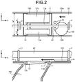
- FIG. 2 shows schematic diagrams illustrating a state where the gate is closed.
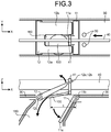
- FIG. 3 shows schematic diagrams illustrating a state where the gate is opened.
- the upper diagrams of FIG. 2 and FIG. 3 each show a view of a transport surface of a transport path 30 as viewed from a Z-axis positive direction side with a direction perpendicular to the transport surface being defined as a Z axis.
- the lower diagrams of FIG. 2 and FIG. 3 each show the transport path 30 as viewed from a Y-axis negative direction side when the width direction of the transport path 30 being defined as a Y axis.
- the coordinate axes are shown such that the correspondence between each figure can be understood.
- a coin 100 is transported on the transport path 30 in an X-axis negative direction (transport direction).
- the coin 100 is transported in a state where the coin surfaces is parallel to the transport surface of the transport path 30.
- a transport belt 40 is disposed along the transport path 30, above the transport path 30 (in the Z-axis positive direction).
- a plurality of transport pins 41 are mounted on the transport belt 40 at equal intervals.
- Openings connected to the chutes 160 are formed in the transport surface of the transport path 30.
- Each opening has a rectangular shape.
- a gate for closing and opening the opening is disposed at each opening.
- the gate includes a first member 11 disposed upstream in the transport direction, and a second member 12 disposed downstream in the transport direction.
- the upper surface of the first member 11 and the upper surface of the second member 12 form a flat surface that is substantially flush with the transport surface of the transport path 30. That is, the first member 11 and the second member 12 form a part of the transport surface on which coins are transported.
- the coin 100 pushed by the transport pin 41 passes over the upper surfaces of the first member 11 and the second member 12 in the closed position and is transported further downstream along the transport path 30.
- Side walls 30a and 30b are disposed at both sides in the width direction (Y axis direction) of the transport path 30, respectively. Movement of coins in the transport path width direction is restricted by the side wall 30a and the side wall 30b. The dimension and the positional relationship of each component are set such that all coins of a plurality of denominations having different diameters can be transported along the transport path 30 between the side wall 30a and the side wall 30b.
- the coin 100 is transported in a state where the coin 100 is shifted to the side wall 30b.
- D diameter of a coin having a maximum diameter
- d diameter of a coin having a minimum diameter
- the width w1 of the transport path 30 shown in FIG. 2 is set to a value larger than the maximum coin diameter D (w1>D).
- the distance w2 between the transport pin 41 and the side wall 30b is set to a value smaller than the minimum coin diameter d (w2 ⁇ d).
- a sensor 50 for detecting the coin 100 is disposed upstream of the opening of the chute 160 in the transport direction.
- the coin handling apparatus 1 uses the sensor 50 to detect the coming of the coin 100 to be dropped.
- the coin handling apparatus 1 rotates the first member 11 and the second member 12 from the closed position shown in FIG. 2 to an opened position shown in FIG. 3 to open the gate.
- the gate is opened, the coin 100 is dropped into the chute 160 through the opening as shown in FIG. 3 .
- the dropped coin 100 is stored in the cassette 130 or the storage unit 140. After the coin 100 is dropped, the coin handling apparatus 1 closes the gate again.
- the second member 12 includes two claws 12a and 12b. As shown in FIG. 2 , the gap a between the claw 12a and the claw 12b is wider than the length b in the transport path width direction of the transport pin 41 (a>b).
- the first member 11 includes a claw 11a. As shown in FIG. 2 , the claw 11a is located between the two claws 12a and 12b of the second member 12 when the gate is in the closed position. When the gate is in the closed position, the claw 11a of the first member 11 and the claws 12a and 12b of the second member 12 close the opening of the chute 160. The three claws 11a, 12a, and 12b close substantially the entire area of the opening.
- the first member 11 is rotatably supported at an end portion thereof on the upstream side in the transport direction by a shaft 11b.
- the shaft 11b is disposed on the upstream side in the transport direction within the opening such that the axial direction thereof coincides with a direction (Y axis direction) perpendicular to the transport direction.
- a planar shape of the first member 11 as viewed from above is a T-shape in which the claw 11a having a substantially rectangular thin plate shape extends downstream in the transport direction from a tubular main body through which the shaft 11b is inserted.
- the second member 12 is rotatably supported at an end portion thereof on the downstream side in the transport direction by a shaft 12c.
- the shaft 12c is disposed on the downstream side in the transport direction within the opening such that the axial direction thereof coincides with the direction (Y axis direction) perpendicular to the transport direction.
- a planar shape of the second member 12 as viewed from above is a U-shape in which the two claws 12a and 12b each having a substantially rectangular thin plate shape extend parallel to each other upstream in the transport direction from a tubular main body through which the shaft 12c is inserted.
- the first member 11 and the second member 12 rotate between the closed position shown in FIG. 2 and the opened position shown in FIG. 3 .
- the first member 11 rotates around the shaft 11b from the closed position to the opened position at the lower side.
- the claw 11a moves to the lower side of the transport surface.
- the second member 12 rotates around the shaft 12c from the closed position to the opened position at the upper side.
- the claws 12a and 12b move to the upper side of the transport surface.
- the lower side is a Z-axis negative direction. Specifically, in the direction perpendicular to the transport surface, the lower side is the direction toward the inner side of the coin handling apparatus 1 with respect to the transport surface.
- the upper side is the Z-axis positive direction. Specifically, in the direction perpendicular to the transport surface, the upper side is the direction toward the outer side of the coin handling apparatus 1 with respect to the transport surface.
- the second member 12 rotates to a position at which the ends, on the upstream side in the transport direction, of the claws 12a and 12b become higher than the lower end of the transport pin 41 and the lower end of the transport belt 40.
- the transport belt 40 and the transport pin 41 pass between the claw 12a and the claw 12b of the second member 12. That is, the second member 12 has a shape in which a part thereof on the upstream side in the transport direction is cut out such that the transport belt 40 and the transport pin 41 can pass therethrough when the second member 12 is at the opened position.
- the claw 11a of the first member 11 which is disposed so as to oppose the second member 12, closes the cut-out area of the second member 12 such that coins are not dropped through this cut-out area.
- the first member 11 rotates downward as the second member 12 rotates upward, such that the claw 11a does not prevent a coin from being dropped.
- a distance c shown in the lower diagram of FIG. 3 indicates the distance from the center of the shaft 11b of the first member 11 to a position at which the coin 100 collides against the lower surface of the second member 12 of the opened position when the coin 100 moves straight along the transport surface.
- the distance c is set so as to be larger than half the diameter D of the coin having a maximum diameter (c>(D/2)).
- the coin 100 When the coin 100 is transported at a high speed, the inertial force acting on the coin 100 is increased, so that the coin 100 may move in the transport direction even after the support of the lower coin surface is lost.
- the coin 100 collides against the lower surface of the second member 12 of the opened position and is dropped. That is, the second member 12 rotates to the opened position at which at least a part thereof is higher than the coin 100 on the transport surface, and functions as an obstacle that prevents passage of the coin 100. Because of both the function of the second member 12 as an obstacle and the influence of gravity, the direction of movement of the coin 100 is changed.
- the second member 12 functions as an obstacle for the coin 100 that is to move past the opening, and thus the coin 100 is reliably dropped into the chute 160.
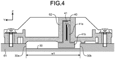
- the coin handling apparatus 1 includes a guide member 62 that guides the transport pins 41.
- FIG. 4 illustrates an example of the guide member 62.
- FIG. 4 shows a view of the transport path 30 as viewed from the downstream side in the transport direction (from the X-axis negative direction side).
- the position of the guide member 62 is fixed with respect to the transport path 30.
- the guide member 62 is fixed to a member 61 on which the transport path 30 is formed.
- the guide member 62 extends along the transport belt 40 and guides the transport pins 41 over substantially the entire area of the transport path 30.
- a cross-sectional shape of each transport pin 41 which is mounted on the transport belt 40, is a T-shape including a vertical portion 41a and a horizontal portion 41b.
- a groove is formed on the guide member 62 so as to correspond to the vertical portion 41a of the transport pin 41.
- the vertical portion 41a of the transport pin 41 moves while being guided by the groove, and the horizontal portion 41b located outside the groove pushes a coin. Movement of the transport pin 41 in the transport path width direction (Y axis direction) and the upward direction (Z-axis positive direction) is restricted by the groove of the guide member 62.
- the distance between the lower surface of the transport pin 41 and the transport surface of the transport path 30 is set to a value smaller than the thickness of a coin having a minimum thickness among coins to be handled.
- the distance is set to 0.3 to 0.5 mm.
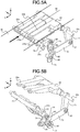
- FIGS. 5A and 5B illustrate an example of the gate.
- FIG. 5A illustrates a state where the gate is closed
- FIG. 5B illustrates a state where the gate is opened.
- An arrow shown in FIG. 5A indicates the transport direction of coins
- a broken line shown in FIG. 5A indicates a position on which the transport belt 40 and the transport pins 41 pass.
- the gate shown in FIGS. 5A and 5B closes and opens the opening formed in the transport surface by using two members that are a first member 21 and the second member 22.
- the first member 11 shown in FIG. 2 and FIG. 3 includes one claw 11a
- the first member 21 shown in FIGS. 5A and 5B includes two claws 21a and 21b.
- the structure shown in FIGS. 5A and 5B is realized by reducing the width, in the transport path width direction, of the claw 12b of the second member 12 shown in FIG. 2 and FIG. 3 and adding the claw of the first member 11 to the width-reduced area.
- the first member 21 and the second member 22 are in a closed position shown in FIG. 5A , substantially the entire area of the opening formed in the transport path 30 is closed by the claws 21a and 21b of the first member 21 and the claws 22a and 22b of the second member 22.
- the gate shown in FIGS. 5A and 5B includes a link mechanism that connects the first member 21 and the second member 22.
- the link mechanism is constituted by connecting plates including three plates 71, 72, and 74 each having an I-shaped thin plate shape, and one plate 73 having an L-shaped thin plate shape.
- the second member 22 includes: a main body through which a shaft 22c is inserted; and the two claws 22a and 22b that extend onto a shaft 21c of the first member 21 from the main body.
- the second member 22 rotates from the closed position shown in FIG. 5A to the opened position shown in FIG. 5B and returns to the closed position, the tips of the claws 22a and 22b come into contact with the shaft 21c of the first member 21 and the second member 22 stops.
- the shaft 22c is fixed to the main body of the second member 22.
- the plate 71 is fixed to the shaft 22c.
- An axial direction of the shaft 22c coincides with the direction (Y axis direction) perpendicular to the transport direction.
- the shaft 22c is rotatably supported at both ends thereof. When the shaft 22c rotates, the second member 22 and the plate 71 rotate together with the shaft 22c.
- the plate 71 is fixed at one end side thereof to the shaft 22c and rotatably connected at another end side thereof to the plate 72 by a shaft 81.
- the plate 72 is connected at one end side thereof to the plate 71 and rotatably connected at another end side thereof to the plate 73 by a shaft 82.
- the L-shaped plate 73 is connected at a corner of the L shape thereof to the plate 72.
- the plate 73 is rotatably supported at one end side thereof by a shaft 83 and rotatably connected at another end side thereof to the plate 74 by a shaft 84.
- the plate 74 is connected at one end side thereof to the plate 73 and rotatably connected at another end side thereof to a shaft 85.
- the axial directions of the shafts 81 to 85 coincide with the direction (Y axis direction) perpendicular to the transport direction.
- the first member 21 includes: a main body through which the shaft 21c is inserted; and the two claws 21a and 21b that extend from the main body toward the downstream side in the transport direction.
- the shaft 21c is fixed to the main body of the first member 21.
- An axial direction of the shaft 21c coincides with the direction (Y axis direction) perpendicular to the transport direction.
- the shaft 21c is rotatably supported at both ends thereof.
- the first member 21 includes the shaft 85 at a position away from the shaft 21c on the downstream side in the transport direction (on the X-axis negative direction side).
- the shaft 85 is fixed to the claw 21b of the first member 21. When the shaft 85 is pulled downward, the first member 21 rotates downward around the shaft 21c.
- a plate 75 is fixed at one end side thereof to the shaft 21c and fixed at another end side thereof to the shaft 85.
- a positioning member that is not shown is disposed outside the transport path 30 so as to correspond to the position of the plate 75.
- the positioning member is fixed at a position at which the lower surface thereof is in contact with the upper surface of the plate 75 of the closed position shown in FIG. 5A .
- the upper surface of the plate 75 comes into contact with the lower surface of the positioning member and the first member 21 stops.
- a part of the upper surface of the claw 21b of the first member 21 also comes into contact with the lower surface of the positioning member.
- the method for stopping the first member 21 at the closed position is not limited to the described method. For example, only the plate 75 may be brought into contact with the positioning member, or only a part of the upper surface of the first member 21 may be brought into contact with the positioning member.
- FIGS. 6A to 6C are schematic diagrams for describing an opening and closing operation of the gate by the link mechanism.
- FIG. 6A illustrates a state where the gate is closed, that is, a state where the first member 21 and the second member 22 are in the closed position.
- FIG. 6C illustrates a state where the gate is opened, that is, a state where the first member 21 and the second member 22 are in the opened position.
- FIG. 6B illustrates a state in the middle of opening of the gate, that is, a state in the middle of movement of the first member 21 and the second member 22 from the closed position to the opened position.
- the positions of the shaft 21c, the shaft 22c, and the shaft 83 are fixed.
- the upper surfaces of the first member 21 and the second member 22 form a flat surface that is substantially flush with the transport surface of the transport path 30.
- a coin being transported on the transport path 30 passes over the first member 21 and the second member 22 and is transported further downstream in the transport direction.
- the shaft 22c shown in FIG. 6A is driven to rotate clockwise. While closing the gate, the shaft 22c shown in FIG. 6C is driven to rotate counterclockwise.
- the driving unit that is not shown rotates the shaft 22c between the closed position shown in FIG. 6A and the opened position shown in FIG. 6C . That is, the driving unit rotates the second member 22 between the closed position and the opened position.
- a rotary solenoid swing selector
- the driving unit is just one example of a drive motor that could be used to control movement of the gate.
- Other electromechanical devices may be employed to control the opening and closing of the gate.
- the second member 12 starts rotating from the closed position to the opened position with rotation of the shaft 22c as shown by an arrow in FIG. 6B .
- the plate 71 which is fixed at one end thereof to the shaft 22c, rotates clockwise. By the rotation of the plate 71, the position of the plate 72 moves to the upstream side in the transport direction (the left side in FIGS. 6A to 6C ).
- the L-shaped plate 73 which is supported by the shaft 83, is pushed at the corner of the L shape thereof by the plate 72 to rotate counterclockwise. By the rotation of the plate 73, the plate 74 moves downward while rotating.
- the first member 21 starts rotating from the closed position to the opened position with the downward movement of the plate 74.
- the first member 21 and the second member 22 that have started rotating as shown in FIG. 6B stop at a maximum position in a preset operating range of the driving unit.
- This position is the opened position at which the first member 21 and the second member 22 stop.
- FIG. 6C illustrates the first member 21 and the second member 22 in the opened position.
- the link mechanism which causes the first member 21 and the second member 22 to move in conjunction with each other, is formed such that a rotation angle f1 of the first member 21 shown in FIG. 6C is larger than a rotation angle f2 of the second member 22.
- the gap between the first member 21 and the second member 22 is larger on the downstream side than on the upstream side in the transport direction.
- the claws 22a and 22b of the second member 22 disposed to support, from below, a coin being transported on the transport path 30 move to the opened position.
- the claws 22a and 22b are located above the coin and the coin is supported only by the first member 21.
- a small-diameter coin has a small area of contact with the first member 21, and thus the lower coin surface the support of which has been lost easily moves downward and the coin surfaces stand up.
- the gap may be clogged with a standing small-diameter coin.
- the angles f1 and f2 are set such that clogging with a standing small-diameter coin is prevented.
- the angles f1 and f2 are set such that, even at a position at which the gap between the upper surface of the first member 21 and the lower surface of the second member 22 at the opened position shown in FIG. 6C is the narrowest, the gap is larger than the minimum diameter d of the coin having a minimum diameter.
- the first member 21 greatly rotates downward.
- the second member 22 rotates upward to a position at which the second member 22 prevents passage of a coin transported thereto on the transport path 30.
- the angles f1 and f2 are set such that the gap between the first member 21 and the second member 22 becomes wide and the rotation angle f1 of the first member 21 is larger than the rotation angle f2 of the second member 22.
- the link mechanism is formed such that: the angle f1 by which the first member 21 rotates from the closed position to the opened position is about 65 degrees; and the angle f2 by which the second member 22 rotates from the closed position to the opened position is about 20 degrees.
- the driving unit drives the shaft 22c shown in FIG. 6C to rotate counterclockwise in order to close the gate.
- the respective plates 71 to 74 which form the link mechanism, move in directions opposite to those when the gate is opened.
- the first member 21 and the second member 22 return from the opened position shown in FIG. 6C through the intermediate state shown in FIG. 6B to the closed position shown in FIG. 6A to close the gate.
- FIGS. 7A and 7B are schematic diagrams illustrating an example in which the shapes of the first member and the second member shown in FIGS. 5A and 5B are different.
- FIG. 7A illustrates a state where the gate is closed
- FIG. 7B illustrates a state where the gate is opened.
- An arrow shown in FIG. 7A indicates the transport direction of coins transported on the transport path 30, and a broken line in FIG. 7A indicates a position on which the transport belt 40 and the transport pins 41 pass.
- the present embodiment is not limited to the above described examples in which substantially the entire area of the opening formed in the transport path 30 is closed when the gate is closed as shown in FIG. 2 and FIG. 5A .
- a part of the opening is not closed and a gap is left as shown in FIG. 7A . It is allowable that a gap leading to the chute 160 is left between a first member 31 and a second member 32 in the closed position as long as coins transported on the transport path 30 are not dropped through the gap when the gate is being closed.
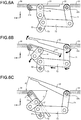
- FIGS. 8A and 8B each show schematic diagrams illustrating a coin handling apparatus which is not within the scope of the present invention in which the opening and closing operation of the gate is different.
- the upper diagrams of FIGS. 8A and 8B each illustrate a state where the gate is closed by a plurality of members 201 and 202 in a closed position
- the lower diagrams of FIGS. 8A and 8B each illustrate the respective members 201 and 202 that move to an opened position to open the gate.
- the gate shown in FIG. 8A includes the members 201 and 202 that are disposed so as to be slidable.
- the two members 201 and 202 which close the opening of the chute 160 as shown in the upper diagram of FIG. 8A , move in parallel to both outer sides in the transport path width direction, respectively, as shown in the lower diagram of FIG. 8A to open the opening.
- the members 201 and 202 shown in the upper diagram of FIG. 8A may be rotatably supported by the side walls 30a and 30b of the transport path 30 as shown in the upper diagram of FIG. 8B .
- the opening of the chute 160 can be opened by rotating the two members 201 and 202 downward as shown in the lower diagram of FIG. 8B .
- FIG. 9 shows schematic diagrams illustrating still another coin handling apparatus which is not within the scope of the present invention in which the opening and closing operation of the gate is different.
- the upper diagram of FIG. 9 illustrates a state where the gate is closed by a plurality of members 211 and 212 in a closed position
- the lower diagram of FIG. 9 illustrates the respective members 211 and 212 that move to an opened position to open the gate.
- the gate shown in FIG. 9 includes the members 211 and 212 that are disposed so as to be rotatable to the outer side in the transport path width direction.
- the two members 211 and 212 which close the opening of the chute 160 as shown in the upper diagram of FIG. 9 , rotate around shafts 211a and 212a, respectively, to the outside of the transport path as shown in the lower diagram of FIG. 9 to open the opening.
- the shafts 211a and 212a are disposed downstream of the members 211 and 212 in the transport direction.
- the shafts 211a and 212a are disposed upstream of the members 211 and 212 in the transport direction.
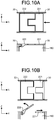
- FIGS. 10A and 10B show schematic diagrams illustrating a coin handling apparatus which is not within the scope of the present invention in which the gate includes a plurality of types of members having different opening and closing operations.
- FIG. 10A illustrates a state where the gate is closed by a plurality of members 221 and 222 in a closed position
- FIG. 10B illustrates the respective members 221 and 222 that move to an opened position to open the gate.
- the upper diagrams of FIGS. 10A and 10B each show a view of the transport path 30 as viewed from above
- the lower diagrams of FIGS. 10A and 10B each show a view of the transport path 30 as viewed from a lateral side.
- FIG. 10A An arrow shown in FIG. 10A indicates the transport direction of coins.
- the gate includes the first member 221 and the second member 222.
- the first member 221 slides and is retracted below the transport surface.
- the second member 222 rotates upward from the transport surface like the second members 12 and 22 shown in FIG. 2 and FIGS. 5A and 5B .
- the second member 222 has a thin plate shape including a recessed part obtained by cutting out a part thereof on the upstream side in the transport direction.
- the first member 221 has a thin plate shape including a projected part formed so as to correspond to the recessed part of the second member 222.
- the gate is closed, the recessed part of the second member 222 is closed by the projected part of the second member 222. Substantially the entire area of the opening of the chute 160 can be closed by the first member 221 and the second member 222.
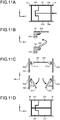
- FIGS. 11A to 11D are schematic diagrams illustrating coin handling apparatus which is not within the scope of the present invention and comprises gates including three or more members.
- FIG. 11A shows a view of the transport path 30, as viewed from above, in a state where the gate is closed by a plurality of members 231 to 233 in a closed position.
- An arrow in FIG. 11A indicates the transport direction of coins.
- the first member 231 and the second member 232 are rotatably supported by the side walls 30a and 30b of the transport path 30, respectively.
- the third member 233 is disposed so as to be rotatable upward from the transport surface.
- the third member 233 has a thin plate shape including a recessed part obtained by cutting out a part thereof on the upstream side in the transport direction.
- the first member 231 and the second member 232 each have a thin plate shape including a projected part formed on the downstream side in the transport direction so as to correspond to the recessed part of the third member 233.
- the gate is closed, the recessed part of the third member 233 is closed by the projected part of the first member 231 and the projected part of the second member 232. Substantially the entire area of the opening of the chute 160 can be closed by the first member 231, the second member 232, and the third member 233.
- the upper diagram of FIG. 11B shows a view of the third member 233 in the closed position as viewed from a lateral side of the transport path 30.
- the lower diagram of FIG. 11B illustrates the third member 233 that rotates to an opened position.
- the upper diagram of FIG. 11C shows a view of the first member 231 and the second member 232 in the closed position as viewed from the downstream side in the transport direction
- the lower diagram of FIG. 11C illustrates the first member 231 and the second member 232 that rotate to the opened position. While opening the gate, the third member 233 rotates upward as shown in FIG. 11B , and the first member 231 and the second member 232 rotate downward as shown in FIG. 11C .
- FIG. 11D illustrates an example in which the third member 233 shown in FIG. 11A is divided into two members 241 and 242.
- the respective members 241 and 242 can rotate upward similar to the third member 233 shown in FIG. 11B to open the gate.
- the gate may include three or more members.
- the transport path 30 is provided so as to be inclined, and a coin is transported in a state where the coin is shifted to the one side wall 30b.
- the configuration of the transport path 30 is not limited thereto, and the transport path 30 may be provided horizontally.
- a plurality of members forming the gate close substantially the entire area of the opening formed in the transport surface of the transport path 30.
- a partial area of the opening may be closed as long as coins transported on the transport path 30 are not dropped into the opening when the gate is being closed. That is, a gap may be formed between the members in the closed position.
- the first member 11 has a shape to close at least a part of the cut-out area.
- the shape of the claw 11a of the first member 11 shown in FIG. 2 may be a shape that is short in the X axis direction or thin in the Y axis direction.
- each member forming the gate and movement of each member when opening and closing the gate are not particularly limited as long as coins on the transport path 30 are not dropped into the chute 160 when the gate is closed, and coins on the transport path 30 can be dropped into the chute 160 when the gate is opened.
- each member may have a mesh shape with through holes or may have a strip shape with long though holes.
- a member that moves in parallel in the up-down direction may move upward from a closed position, at which the member forms a part of the transport surface of the transport path 30, to an opened position in order to prevent passage of a coin transported along the transport surface, thereby dropping the coin into the opening.
- the coin handling apparatus includes: a transport path having a transport surface provided with an opening portion through which a coin is dropped; a transport unit configured to transport a coin on the transport surface along the transport path from upstream to downstream in a transport direction; a gate for opening and closing the opening portion of the transport surface, wherein the gate is configured to move between a first position in which the opening portion is closed by the gate and the coin transported by the transport unit is not dropped through the opening, and a second position in which the opening position is opened by the gate and the coin is dropped through the opening portion; and a driving unit configured to control the gate to move between the first position and the second position, wherein the gate includes a first member disposed upstream in the transport direction and a second member disposed downstream in the transport direction, upper surfaces of the first and second members form a flat surface being substantially flush w ith the transport surface of the transport path when the gate is i n the first position, and the driving unit is configured to drivet he first and second members to move the gate between the first
- the plurality of members of the gate include a member configured to prevent passage of a coin transported on the transport surface and drop the coin into the opening, when the gate is in the opened position.
- the gate is configured to form a flat surface that is substantially flush with the transport surface when the gate is in the closed position.
- the plurality of members of the gate include: a first member disposed upstream in a transport direction of coins and configured to start rotating in a first direction from the closed position toward the opened position; and a second member disposed downstream in the transport direction and configured to start rotating in a second direction opposite to the first direction, from the closed position toward the opened position.
- the first direction and the second direction are perpendicular to the transport surface.
- the first member is configured to rotate around a first shaft disposed upstream in the transport direction within the opening
- the second member is configured to rotate around a second shaft disposed downstream in the transport direction within the opening.
- the transport unit includes a transport pin configured to transport a coin on the transport surface by pushing the coin, and the second member has a shape in which an area, where the transport pin passes, when the gate is in the opened position, is cut out.
- the first member has a shape to close at least a part of the cut-out area of the second member when the gate is in the closed position.
- the coin handling apparatus includes a link mechanism configured to connect the first member and the second member such that the first member and the second member move in conjunction with each other when opening and closing the gate.
- An angle by which the first member rotates from the closed position to the opened position is larger than an angle by which the second member rotates from the closed position to the opened position.
- the coin handling apparatus has the openings formed in the transport path for coins, and dropping of a coin into each opening is controlled by opening and closing the gate including a plurality of members.
- each member With the structure to close the opening by a plurality of members, each member can be reduced in weight and movement of each member for opening and closing the opening can be reduced, as compared to the case where one member closes the opening. Accordingly, even when coins are transported on the transport path at a high speed, only a coin to be dropped can be dropped into the opening.
- At least a part of at least one of the members forming the gate is located above the transport surface when the gate is opened, thereby preventing passage of a coin transported thereto on the transport surface.
- the coin collides against the part located above the transport surface and is dropped, so that the coin can be reliably dropped into the opening.
- the coin handling apparatus is useful for dropping only a coin to be dropped, into an opening formed in a transport path.
Landscapes
- Physics & Mathematics (AREA)
- General Physics & Mathematics (AREA)
- Attitude Control For Articles On Conveyors (AREA)
Description
- The present invention relates to a coin handling apparatus that handles coins.
- Conventionally, coin handling apparatuses that perform depositing and dispensing of coins have been used.
Japanese Laid-Open Patent Publication No. 2013-122744 JP 2011 039593A EP 1808822 A1 discloses a coin processing device including a passage having openings. A coin is dropped through the openings by using gates.EP 1927955A1 discloses a compact coin depositing and dispensing machine comprising a conveying means for conveying, one by one, coins, accepted in a coin acceptance port, in a depositing and conveying direction, and conveying, one by one, coins, to be ejected to a coin ejection port, in a dispensing and conveying direction reverse the depositing and conveying direction. A plurality of accommodating and ejecting units are disposed along the conveying means. At positions of a coin passage at the respective coin outlet/inlets are disposed sorting members that selectively sort coins according to whether a coin is to be output or input through the respective coin outlet/inlets or whether a coin being conveyed by the conveying means is to be passed to a downstream side in the conveying direction. The sorting member has, in an integral manner, a coin guiding portion, guiding a coin to the coin outlet/inlet, a closing portion, preventing the entry of a coin into the coin outlet/inlet, and a supporting portion, swingably supporting the coin guiding portion and the closing portion.US 4615350A discloses a coin dispensing device having a ejector member opposite a coin runner. - In the conventional art described above, however, coins cannot be correctly sorted in some cases. For example, there is a possibility that the gates cannot be opened and closed in time when a transport speed of coins is high. By changing the shape of each gate into a shape for closing only a part of the opening of the inlet to reduce the weight of the gate, the opening/closing speed of the gate can be increased. In this case, however, even in a state where the gate is closed, a small-diameter coin may be dropped through a gap in the gate into the opening.
- The present invention has been made in view of the problem in the conventional art described above, and an object of the present invention is to provide a coin handling apparatus that can drop a coin to be dropped, into an opening formed in a transport path.
- A coin handling apparatus according to one aspect of the present invention is provided in claim 1.
- The above and other objects, features, advantages and technical and industrial significance of this invention will be better understood by reading the following detailed description of presently preferred embodiments of the invention, when considered in connection with the accompanying drawings.
-
-
FIGS. 1A and 1B illustrate a coin handling apparatus according to an embodiment; -
FIG. 2 shows schematic diagrams illustrating a state where a gate is closed; -
FIG. 3 shows schematic diagrams illustrating a state where the gate is opened; -
FIG. 4 illustrates an example of a guide member that guides transport pins; -
FIGS. 5A and 5B illustrate an example of the gate; -
FIGS. 6A to 6C are schematic diagrams for describing an opening and closing operation of the gate by a link mechanism; -
FIGS. 7A and 7B are schematic diagrams illustrating an example in which the shapes of a first member and a second member shown inFIGS. 5A and 5B are different; -
FIGS. 8A and 8B each show schematic diagrams illustrating a coin handling apparatus which is not within the scope of the present invention in which the opening and closing operation of the gate is different; -
FIG. 9 shows schematic diagrams illustrating still another coin handling apparatus which is not within the scope of the present invention in which the opening and closing operation of the gate is different; -
FIGS. 10A and 10B show schematic diagrams illustrating a coin handling apparatus which is not within the scope of the present invention in which the gate includes a plurality of types of members having different opening and closing operations; and -
FIGS. 11A to 11D show schematic diagrams illustrating a coin handling apparatus which is not within the scope of the present invention having a gate including three or more members. - Hereinafter, an embodiment of the coin handling apparatus according to the present invention will be described with reference to the accompanying drawings.
FIGS. 1A and 1B illustrate a coin handling apparatus 1 according to the present embodiment.FIG. 1A is an external view of the coin handling apparatus 1.FIG. 1B is a schematic diagram illustrating the internal structure of the coin handling apparatus 1. - As shown in
FIG. 1A , the coin handling apparatus 1 includes a depositingunit 110 for depositing coins, and a dispensingunit 120 for dispensing coins. The depositingunit 110 is formed on an upper surface of the coin handling apparatus 1. The dispensingunit 120 is formed on a front surface of the coin handling apparatus 1. In addition to thedepositing unit 110 and thedispensing unit 120, the coin handling apparatus 1 includes acassette 130,storage units 140, a transport unit 150 (150a, 150b), arecognition unit 170, and afeeding unit 180 as shown inFIG. 1B . - When depositing coins to the coin handling apparatus 1, the depositing
unit 110 receives the coins. The coins received by the depositingunit 110 are dropped into thefeeding unit 180. Thefeeding unit 180 stores the dropped coins and feeds out the stored coins one by one to a transport path constituting thetransport unit 150a. Thetransport unit 150a transports the coins fed out by thefeeding unit 180, along the transport path. Therecognition unit 170 recognizes and counts the coins transported on the transport path. For example, therecognition unit 170 recognizes denominations, authenticity, and fitness of the coins. Therecognition unit 170 counts the number and the monetary amount of the coins for each denomination, and counts the total number and the total monetary amount of the coins. A destination to store each coin is determined on the basis of the result of recognition by therecognition unit 170. - A plurality of
chutes 160 are connected to the transport path. Thechutes 160 are disposed on the transport path downstream of therecognition unit 170 in a transport direction. Eachchute 160 connects the transport path to any one of thecassette 130 and thestorage units 140.FIG. 1B shows some chutes to avoid complexity. An opening of eachchute 160 that is formed in the transport path is normally closed by a gate. Coins being transported on the transport path passes over the closed gate. When the gate at thechute 160 corresponding to the destination to store a coin is opened, the coin is dropped into thechute 160 through the opening in the transport path. The dropped coin is stored in thecassette 130 or thestorage unit 140 through thechute 160. For example, coins to be collected from the coin handling apparatus 1 are stored in thecassette 130, and coins to be deposited in the coin handling apparatus 1 are stored in thestorage units 140 for each denomination. The gate will be described later. - When dispensing coins from the coin handling apparatus 1, the
storage units 140 feed out coins to be dispensed, one by one. A transport path constituting thetransport unit 150b is disposed below thestorage units 140. The coins fed out from thestorage units 140 are dropped onto the transport path of thetransport unit 150b. The transport path is provided so as to receive coins fed out from all thestorage units 140 and transport the received coins to thefeeding unit 180. - The
transport unit 150b transports coins received on the transport path below thestorage units 140, toward the front side (the left side inFIG. 1B ) of the apparatus, and then transports the coins upward. The coins transported upward are dropped into thefeeding unit 180. By opening a gate at a bottom surface of thefeeding unit 180, the coins dropped into thefeeding unit 180 are dispensed from the dispensingunit 120. The coins discharged to thedispensing unit 120 can be taken out through an opening in the front surface of the coin handling apparatus 1. - The
cassette 130 is detachably mounted to the coin handling apparatus 1. Thecassette 130 stores coins dropped from thechutes 160 and feeds out the stored coins. Coins fed out from thecassette 130 are dropped onto the transport path of thetransport unit 150b, similar to coins fed out from thestorage units 140. For example, thecassette 130 is used for collection of and replenishing with coins. - Next, the gate will be described.
FIG. 2 shows schematic diagrams illustrating a state where the gate is closed.FIG. 3 shows schematic diagrams illustrating a state where the gate is opened. The upper diagrams ofFIG. 2 andFIG. 3 each show a view of a transport surface of atransport path 30 as viewed from a Z-axis positive direction side with a direction perpendicular to the transport surface being defined as a Z axis. The lower diagrams ofFIG. 2 andFIG. 3 each show thetransport path 30 as viewed from a Y-axis negative direction side when the width direction of thetransport path 30 being defined as a Y axis. InFIG. 2 and the subsequent figures, the coordinate axes are shown such that the correspondence between each figure can be understood. - As shown by an arrow in
FIG. 2 , acoin 100 is transported on thetransport path 30 in an X-axis negative direction (transport direction). Thecoin 100 is transported in a state where the coin surfaces is parallel to the transport surface of thetransport path 30. Atransport belt 40 is disposed along thetransport path 30, above the transport path 30 (in the Z-axis positive direction). A plurality of transport pins 41 are mounted on thetransport belt 40 at equal intervals. By thetransport unit 150a driving thetransport belt 40 in the transport direction, the transport pins 41 move in the transport direction. The movingtransport pin 41 pushes thecoin 100 from the rear side (from the upstream side in the transport direction), whereby thecoin 100 is transported in the transport direction. - Openings connected to the
chutes 160 are formed in the transport surface of thetransport path 30. Each opening has a rectangular shape. A gate for closing and opening the opening is disposed at each opening. The gate includes afirst member 11 disposed upstream in the transport direction, and asecond member 12 disposed downstream in the transport direction. - When the gate is in a closed position where the gate is closed as shown in
FIG. 2 , the upper surface of thefirst member 11 and the upper surface of thesecond member 12 form a flat surface that is substantially flush with the transport surface of thetransport path 30. That is, thefirst member 11 and thesecond member 12 form a part of the transport surface on which coins are transported. Thecoin 100 pushed by thetransport pin 41 passes over the upper surfaces of thefirst member 11 and thesecond member 12 in the closed position and is transported further downstream along thetransport path 30. -
Side walls transport path 30, respectively. Movement of coins in the transport path width direction is restricted by theside wall 30a and theside wall 30b. The dimension and the positional relationship of each component are set such that all coins of a plurality of denominations having different diameters can be transported along thetransport path 30 between theside wall 30a and theside wall 30b. - For example, in the case where the
transport path 30 is provided so as to be inclined such that theside wall 30a side is higher in the vertical direction than theside wall 30b side, thecoin 100 is transported in a state where thecoin 100 is shifted to theside wall 30b. When the diameter of a coin having a maximum diameter is denoted by D and the diameter of a coin having a minimum diameter is denoted by d among coins transported on the transport path, the width w1 of thetransport path 30 shown inFIG. 2 is set to a value larger than the maximum coin diameter D (w1>D). The distance w2 between thetransport pin 41 and theside wall 30b is set to a value smaller than the minimum coin diameter d (w2<d). - On the
transport path 30, asensor 50 for detecting thecoin 100 is disposed upstream of the opening of thechute 160 in the transport direction. The coin handling apparatus 1 uses thesensor 50 to detect the coming of thecoin 100 to be dropped. In accordance with the coming of thecoin 100 to be stored in thecassette 130 or thestorage unit 140, the coin handling apparatus 1 rotates thefirst member 11 and thesecond member 12 from the closed position shown inFIG. 2 to an opened position shown inFIG. 3 to open the gate. When the gate is opened, thecoin 100 is dropped into thechute 160 through the opening as shown inFIG. 3 . The droppedcoin 100 is stored in thecassette 130 or thestorage unit 140. After thecoin 100 is dropped, the coin handling apparatus 1 closes the gate again. - The
second member 12 includes twoclaws FIG. 2 , the gap a between theclaw 12a and theclaw 12b is wider than the length b in the transport path width direction of the transport pin 41 (a>b). Thefirst member 11 includes aclaw 11a. As shown inFIG. 2 , theclaw 11a is located between the twoclaws second member 12 when the gate is in the closed position. When the gate is in the closed position, theclaw 11a of thefirst member 11 and theclaws second member 12 close the opening of thechute 160. The threeclaws - The
first member 11 is rotatably supported at an end portion thereof on the upstream side in the transport direction by ashaft 11b. Theshaft 11b is disposed on the upstream side in the transport direction within the opening such that the axial direction thereof coincides with a direction (Y axis direction) perpendicular to the transport direction. As shown inFIG. 2 , a planar shape of thefirst member 11 as viewed from above is a T-shape in which theclaw 11a having a substantially rectangular thin plate shape extends downstream in the transport direction from a tubular main body through which theshaft 11b is inserted. - The
second member 12 is rotatably supported at an end portion thereof on the downstream side in the transport direction by ashaft 12c. Theshaft 12c is disposed on the downstream side in the transport direction within the opening such that the axial direction thereof coincides with the direction (Y axis direction) perpendicular to the transport direction. As shown inFIG. 2 , a planar shape of thesecond member 12 as viewed from above is a U-shape in which the twoclaws shaft 12c is inserted. - The
first member 11 and thesecond member 12 rotate between the closed position shown inFIG. 2 and the opened position shown inFIG. 3 . As shown by an arrow in the lower diagram ofFIG. 3 , thefirst member 11 rotates around theshaft 11b from the closed position to the opened position at the lower side. By the rotation, theclaw 11a moves to the lower side of the transport surface. Thesecond member 12 rotates around theshaft 12c from the closed position to the opened position at the upper side. By the rotation, theclaws - As shown in
FIG. 3 , thesecond member 12 rotates to a position at which the ends, on the upstream side in the transport direction, of theclaws transport pin 41 and the lower end of thetransport belt 40. At this position, thetransport belt 40 and thetransport pin 41 pass between theclaw 12a and theclaw 12b of thesecond member 12. That is, thesecond member 12 has a shape in which a part thereof on the upstream side in the transport direction is cut out such that thetransport belt 40 and thetransport pin 41 can pass therethrough when thesecond member 12 is at the opened position. When the gate is closed, theclaw 11a of thefirst member 11, which is disposed so as to oppose thesecond member 12, closes the cut-out area of thesecond member 12 such that coins are not dropped through this cut-out area. While opening the gate, thefirst member 11 rotates downward as thesecond member 12 rotates upward, such that theclaw 11a does not prevent a coin from being dropped. - A distance c shown in the lower diagram of
FIG. 3 indicates the distance from the center of theshaft 11b of thefirst member 11 to a position at which thecoin 100 collides against the lower surface of thesecond member 12 of the opened position when thecoin 100 moves straight along the transport surface. The distance c is set so as to be larger than half the diameter D of the coin having a maximum diameter (c>(D/2)). Thus, before the leading end, in the transport direction, of thecoin 100 collides against thesecond member 12, more than half of the lower surface of thecoin 100 loses support by the transport surface, so that the leading end moves downward and thecoin 100 is dropped into thechute 160. - When the
coin 100 is transported at a high speed, the inertial force acting on thecoin 100 is increased, so that thecoin 100 may move in the transport direction even after the support of the lower coin surface is lost. In this case, thecoin 100 collides against the lower surface of thesecond member 12 of the opened position and is dropped. That is, thesecond member 12 rotates to the opened position at which at least a part thereof is higher than thecoin 100 on the transport surface, and functions as an obstacle that prevents passage of thecoin 100. Because of both the function of thesecond member 12 as an obstacle and the influence of gravity, the direction of movement of thecoin 100 is changed. Thesecond member 12 functions as an obstacle for thecoin 100 that is to move past the opening, and thus thecoin 100 is reliably dropped into thechute 160. - The coin handling apparatus 1 includes a
guide member 62 that guides the transport pins 41.FIG. 4 illustrates an example of theguide member 62.FIG. 4 shows a view of thetransport path 30 as viewed from the downstream side in the transport direction (from the X-axis negative direction side). The position of theguide member 62 is fixed with respect to thetransport path 30. For example, as shown inFIG. 4 , theguide member 62 is fixed to amember 61 on which thetransport path 30 is formed. Theguide member 62 extends along thetransport belt 40 and guides the transport pins 41 over substantially the entire area of thetransport path 30. - As shown in
FIG. 4 , a cross-sectional shape of eachtransport pin 41, which is mounted on thetransport belt 40, is a T-shape including avertical portion 41a and ahorizontal portion 41b. A groove is formed on theguide member 62 so as to correspond to thevertical portion 41a of thetransport pin 41. Thevertical portion 41a of thetransport pin 41 moves while being guided by the groove, and thehorizontal portion 41b located outside the groove pushes a coin. Movement of thetransport pin 41 in the transport path width direction (Y axis direction) and the upward direction (Z-axis positive direction) is restricted by the groove of theguide member 62. The distance between the lower surface of thetransport pin 41 and the transport surface of thetransport path 30 is set to a value smaller than the thickness of a coin having a minimum thickness among coins to be handled. For example, the distance is set to 0.3 to 0.5 mm. Owing to the restriction by theguide member 62, thetransport pin 41 does not move in the transport path width direction nor does it move in the up-down direction. Accordingly, transport of coins on thetransport path 30 and dropping of coins from thetransport path 30 into thechutes 160 are reliably performed. - Next, a specific example of the gate will be described.
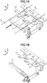
FIGS. 5A and 5B illustrate an example of the gate.FIG. 5A illustrates a state where the gate is closed, andFIG. 5B illustrates a state where the gate is opened. An arrow shown inFIG. 5A indicates the transport direction of coins, and a broken line shown inFIG. 5A indicates a position on which thetransport belt 40 and the transport pins 41 pass. When asecond member 22 has rotated upward to open the gate as shown inFIG. 5B , thetransport belt 40 and thetransport pin 41 pass between aclaw 22a and aclaw 22b. - Similar to the gate shown in
FIG. 2 andFIG. 3 , the gate shown inFIGS. 5A and 5B closes and opens the opening formed in the transport surface by using two members that are afirst member 21 and thesecond member 22. Whereas thefirst member 11 shown inFIG. 2 andFIG. 3 includes oneclaw 11a, thefirst member 21 shown inFIGS. 5A and 5B includes twoclaws FIGS. 5A and 5B is realized by reducing the width, in the transport path width direction, of theclaw 12b of thesecond member 12 shown inFIG. 2 andFIG. 3 and adding the claw of thefirst member 11 to the width-reduced area. When thefirst member 21 and thesecond member 22 are in a closed position shown inFIG. 5A , substantially the entire area of the opening formed in thetransport path 30 is closed by theclaws first member 21 and theclaws second member 22. - The gate shown in
FIGS. 5A and 5B includes a link mechanism that connects thefirst member 21 and thesecond member 22. Thefirst member 21 and thesecond member 22, which are connected to each other by the link mechanism, move in conjunction with each other. The link mechanism is constituted by connecting plates including threeplates plate 73 having an L-shaped thin plate shape. - As shown in
FIG. 5A , thesecond member 22 includes: a main body through which ashaft 22c is inserted; and the twoclaws shaft 21c of thefirst member 21 from the main body. When thesecond member 22 rotates from the closed position shown inFIG. 5A to the opened position shown inFIG. 5B and returns to the closed position, the tips of theclaws shaft 21c of thefirst member 21 and thesecond member 22 stops. - The
shaft 22c is fixed to the main body of thesecond member 22. Theplate 71 is fixed to theshaft 22c. An axial direction of theshaft 22c coincides with the direction (Y axis direction) perpendicular to the transport direction. Theshaft 22c is rotatably supported at both ends thereof. When theshaft 22c rotates, thesecond member 22 and theplate 71 rotate together with theshaft 22c. - The
plate 71 is fixed at one end side thereof to theshaft 22c and rotatably connected at another end side thereof to theplate 72 by ashaft 81. Theplate 72 is connected at one end side thereof to theplate 71 and rotatably connected at another end side thereof to theplate 73 by ashaft 82. The L-shapedplate 73 is connected at a corner of the L shape thereof to theplate 72. Theplate 73 is rotatably supported at one end side thereof by ashaft 83 and rotatably connected at another end side thereof to theplate 74 by ashaft 84. Theplate 74 is connected at one end side thereof to theplate 73 and rotatably connected at another end side thereof to ashaft 85. The axial directions of theshafts 81 to 85 coincide with the direction (Y axis direction) perpendicular to the transport direction. - The
first member 21 includes: a main body through which theshaft 21c is inserted; and the twoclaws shaft 21c is fixed to the main body of thefirst member 21. An axial direction of theshaft 21c coincides with the direction (Y axis direction) perpendicular to the transport direction. Theshaft 21c is rotatably supported at both ends thereof. Thefirst member 21 includes theshaft 85 at a position away from theshaft 21c on the downstream side in the transport direction (on the X-axis negative direction side). Theshaft 85 is fixed to theclaw 21b of thefirst member 21. When theshaft 85 is pulled downward, thefirst member 21 rotates downward around theshaft 21c. - A
plate 75 is fixed at one end side thereof to theshaft 21c and fixed at another end side thereof to theshaft 85. A positioning member that is not shown is disposed outside thetransport path 30 so as to correspond to the position of theplate 75. The positioning member is fixed at a position at which the lower surface thereof is in contact with the upper surface of theplate 75 of the closed position shown inFIG. 5A . When thefirst member 21 rotates from the closed position shown inFIG. 5A to the opened position shown inFIG. 5B and returns to the closed position, the upper surface of theplate 75 comes into contact with the lower surface of the positioning member and thefirst member 21 stops. At this time, a part of the upper surface of theclaw 21b of thefirst member 21 also comes into contact with the lower surface of the positioning member. The method for stopping thefirst member 21 at the closed position is not limited to the described method. For example, only theplate 75 may be brought into contact with the positioning member, or only a part of the upper surface of thefirst member 21 may be brought into contact with the positioning member. - When a driving unit that is not shown rotationally drives one member of the
first member 21 and thesecond member 22, the other member connected by the link mechanism also rotates in conjunction with the one member. An example of an operation of thefirst member 21 and thesecond member 22 will be described with the case where the driving unit rotationally drives theshaft 22c of thesecond member 22. -
FIGS. 6A to 6C are schematic diagrams for describing an opening and closing operation of the gate by the link mechanism.FIG. 6A illustrates a state where the gate is closed, that is, a state where thefirst member 21 and thesecond member 22 are in the closed position.FIG. 6C illustrates a state where the gate is opened, that is, a state where thefirst member 21 and thesecond member 22 are in the opened position.FIG. 6B illustrates a state in the middle of opening of the gate, that is, a state in the middle of movement of thefirst member 21 and thesecond member 22 from the closed position to the opened position. The positions of theshaft 21c, theshaft 22c, and theshaft 83 are fixed. - As shown in
FIG. 6A , in the closed position where the gate is closed, the upper surfaces of thefirst member 21 and thesecond member 22 form a flat surface that is substantially flush with the transport surface of thetransport path 30. A coin being transported on thetransport path 30 passes over thefirst member 21 and thesecond member 22 and is transported further downstream in the transport direction. - While opening the gate, the
shaft 22c shown inFIG. 6A is driven to rotate clockwise. While closing the gate, theshaft 22c shown inFIG. 6C is driven to rotate counterclockwise. The driving unit that is not shown rotates theshaft 22c between the closed position shown inFIG. 6A and the opened position shown inFIG. 6C . That is, the driving unit rotates thesecond member 22 between the closed position and the opened position. For example, a rotary solenoid (swing selector) is used as the driving unit. The rotary solenoid is just one example of a drive motor that could be used to control movement of the gate. Other electromechanical devices may be employed to control the opening and closing of the gate. - The
second member 12 starts rotating from the closed position to the opened position with rotation of theshaft 22c as shown by an arrow inFIG. 6B . Theplate 71, which is fixed at one end thereof to theshaft 22c, rotates clockwise. By the rotation of theplate 71, the position of theplate 72 moves to the upstream side in the transport direction (the left side inFIGS. 6A to 6C ). The L-shapedplate 73, which is supported by theshaft 83, is pushed at the corner of the L shape thereof by theplate 72 to rotate counterclockwise. By the rotation of theplate 73, theplate 74 moves downward while rotating. Thefirst member 21 starts rotating from the closed position to the opened position with the downward movement of theplate 74. - The
first member 21 and thesecond member 22 that have started rotating as shown inFIG. 6B stop at a maximum position in a preset operating range of the driving unit. This position is the opened position at which thefirst member 21 and thesecond member 22 stop.FIG. 6C illustrates thefirst member 21 and thesecond member 22 in the opened position. The link mechanism, which causes thefirst member 21 and thesecond member 22 to move in conjunction with each other, is formed such that a rotation angle f1 of thefirst member 21 shown inFIG. 6C is larger than a rotation angle f2 of thesecond member 22. As a result, in the opened position, the gap between thefirst member 21 and thesecond member 22 is larger on the downstream side than on the upstream side in the transport direction. - While opening the gate, the
claws second member 22 disposed to support, from below, a coin being transported on thetransport path 30 move to the opened position. In the opened position, theclaws first member 21. A small-diameter coin has a small area of contact with thefirst member 21, and thus the lower coin surface the support of which has been lost easily moves downward and the coin surfaces stand up. In the case where a position at which the gap between the upper surface of thefirst member 21 and the lower surface of thesecond member 22 is narrow and the upper surface of thefirst member 21 and the lower surface of thesecond member 22 are substantially parallel to each other as shown inFIG. 6B is set as the opened position, the gap may be clogged with a standing small-diameter coin. Thus, the angles f1 and f2 are set such that clogging with a standing small-diameter coin is prevented. For example, the angles f1 and f2 are set such that, even at a position at which the gap between the upper surface of thefirst member 21 and the lower surface of thesecond member 22 at the opened position shown inFIG. 6C is the narrowest, the gap is larger than the minimum diameter d of the coin having a minimum diameter. - In order to drop a coin into the
chute 160, it is preferable that thefirst member 21 greatly rotates downward. On the other hand, it is sufficient that thesecond member 22 rotates upward to a position at which thesecond member 22 prevents passage of a coin transported thereto on thetransport path 30. Thus, the angles f1 and f2 are set such that the gap between thefirst member 21 and thesecond member 22 becomes wide and the rotation angle f1 of thefirst member 21 is larger than the rotation angle f2 of thesecond member 22. For example, the link mechanism is formed such that: the angle f1 by which thefirst member 21 rotates from the closed position to the opened position is about 65 degrees; and the angle f2 by which thesecond member 22 rotates from the closed position to the opened position is about 20 degrees. - After the gate has been opened and a coin has been dropped into the
chute 160, the driving unit drives theshaft 22c shown inFIG. 6C to rotate counterclockwise in order to close the gate. When theshaft 22c rotates counterclockwise, therespective plates 71 to 74, which form the link mechanism, move in directions opposite to those when the gate is opened. As a result, thefirst member 21 and thesecond member 22 return from the opened position shown inFIG. 6C through the intermediate state shown inFIG. 6B to the closed position shown inFIG. 6A to close the gate. - The structure of the gate is not limited to the above-described examples.
FIGS. 7A and 7B are schematic diagrams illustrating an example in which the shapes of the first member and the second member shown inFIGS. 5A and 5B are different.FIG. 7A illustrates a state where the gate is closed, andFIG. 7B illustrates a state where the gate is opened. An arrow shown inFIG. 7A indicates the transport direction of coins transported on thetransport path 30, and a broken line inFIG. 7A indicates a position on which thetransport belt 40 and the transport pins 41 pass. - The present embodiment is not limited to the above described examples in which substantially the entire area of the opening formed in the
transport path 30 is closed when the gate is closed as shown inFIG. 2 andFIG. 5A . In another example, a part of the opening is not closed and a gap is left as shown inFIG. 7A . It is allowable that a gap leading to thechute 160 is left between afirst member 31 and asecond member 32 in the closed position as long as coins transported on thetransport path 30 are not dropped through the gap when the gate is being closed. - The number of members forming the gate and the opening and closing operation of the gate are not limited to the above-described examples.
FIGS. 8A and 8B each show schematic diagrams illustrating a coin handling apparatus which is not within the scope of the present invention in which the opening and closing operation of the gate is different. The upper diagrams ofFIGS. 8A and 8B each illustrate a state where the gate is closed by a plurality ofmembers FIGS. 8A and 8B each illustrate therespective members - The gate shown in
FIG. 8A includes themembers members chute 160 as shown in the upper diagram ofFIG. 8A , move in parallel to both outer sides in the transport path width direction, respectively, as shown in the lower diagram ofFIG. 8A to open the opening. - The
members FIG. 8A may be rotatably supported by theside walls transport path 30 as shown in the upper diagram ofFIG. 8B . The opening of thechute 160 can be opened by rotating the twomembers FIG. 8B . -
FIG. 9 shows schematic diagrams illustrating still another coin handling apparatus which is not within the scope of the present invention in which the opening and closing operation of the gate is different. The upper diagram ofFIG. 9 illustrates a state where the gate is closed by a plurality ofmembers FIG. 9 illustrates therespective members - The gate shown in
FIG. 9 includes themembers members chute 160 as shown in the upper diagram ofFIG. 9 , rotate aroundshafts FIG. 9 to open the opening. Theshafts members shafts members -
FIGS. 10A and 10B show schematic diagrams illustrating a coin handling apparatus which is not within the scope of the present invention in which the gate includes a plurality of types of members having different opening and closing operations.FIG. 10A illustrates a state where the gate is closed by a plurality ofmembers FIG. 10B illustrates therespective members FIGS. 10A and 10B each show a view of thetransport path 30 as viewed from above, and the lower diagrams ofFIGS. 10A and 10B each show a view of thetransport path 30 as viewed from a lateral side. - An arrow shown in
FIG. 10A indicates the transport direction of coins. The gate includes thefirst member 221 and thesecond member 222. Thefirst member 221 slides and is retracted below the transport surface. Thesecond member 222 rotates upward from the transport surface like thesecond members FIG. 2 andFIGS. 5A and 5B . - The
second member 222 has a thin plate shape including a recessed part obtained by cutting out a part thereof on the upstream side in the transport direction. When thesecond member 222 rotates upward to open the gate, thetransport belt 40 and the transport pins 41 pass through the recessed part cut out from thesecond member 222. Thefirst member 221 has a thin plate shape including a projected part formed so as to correspond to the recessed part of thesecond member 222. When the gate is closed, the recessed part of thesecond member 222 is closed by the projected part of thesecond member 222. Substantially the entire area of the opening of thechute 160 can be closed by thefirst member 221 and thesecond member 222. - As shown in
FIG. 10B , while opening the gate, whereas thefirst member 221 slides to the upstream side in the transport direction, thesecond member 222 rotates upward. -
FIGS. 11A to 11D are schematic diagrams illustrating coin handling apparatus which is not within the scope of the present invention and comprises gates including three or more members.FIG. 11A shows a view of thetransport path 30, as viewed from above, in a state where the gate is closed by a plurality ofmembers 231 to 233 in a closed position. An arrow inFIG. 11A indicates the transport direction of coins. Thefirst member 231 and thesecond member 232 are rotatably supported by theside walls transport path 30, respectively. Similar to thesecond members FIG. 2 andFIGS. 5A and 5B , thethird member 233 is disposed so as to be rotatable upward from the transport surface. - The
third member 233 has a thin plate shape including a recessed part obtained by cutting out a part thereof on the upstream side in the transport direction. When thethird member 233 rotates upward to open the gate, thetransport belt 40 and the transport pins 41 pass through the recessed part cut out from thethird member 233. Thefirst member 231 and thesecond member 232 each have a thin plate shape including a projected part formed on the downstream side in the transport direction so as to correspond to the recessed part of thethird member 233. When the gate is closed, the recessed part of thethird member 233 is closed by the projected part of thefirst member 231 and the projected part of thesecond member 232. Substantially the entire area of the opening of thechute 160 can be closed by thefirst member 231, thesecond member 232, and thethird member 233. - The upper diagram of
FIG. 11B shows a view of thethird member 233 in the closed position as viewed from a lateral side of thetransport path 30. The lower diagram ofFIG. 11B illustrates thethird member 233 that rotates to an opened position. The upper diagram ofFIG. 11C shows a view of thefirst member 231 and thesecond member 232 in the closed position as viewed from the downstream side in the transport direction The lower diagram ofFIG. 11C illustrates thefirst member 231 and thesecond member 232 that rotate to the opened position. While opening the gate, thethird member 233 rotates upward as shown inFIG. 11B , and thefirst member 231 and thesecond member 232 rotate downward as shown inFIG. 11C . -
FIG. 11D illustrates an example in which thethird member 233 shown inFIG. 11A is divided into twomembers respective members third member 233, therespective members third member 233 shown inFIG. 11B to open the gate. As described above, the gate may include three or more members. - In the present embodiment, the
transport path 30 is provided so as to be inclined, and a coin is transported in a state where the coin is shifted to the oneside wall 30b. However, the configuration of thetransport path 30 is not limited thereto, and thetransport path 30 may be provided horizontally. - In the present embodiment, a plurality of members forming the gate close substantially the entire area of the opening formed in the transport surface of the
transport path 30. However, a partial area of the opening may be closed as long as coins transported on thetransport path 30 are not dropped into the opening when the gate is being closed. That is, a gap may be formed between the members in the closed position. For example, as shown inFIG. 2 , in the case where thesecond member 12 has a shape in which the area, where thetransport belt 40 and the transport pins 41 pass at the opened position, is cut out from the upstream side in the transport direction, thefirst member 11 has a shape to close at least a part of the cut-out area. Specifically, the shape of theclaw 11a of thefirst member 11 shown inFIG. 2 may be a shape that is short in the X axis direction or thin in the Y axis direction. - The shape of each member forming the gate and movement of each member when opening and closing the gate are not particularly limited as long as coins on the
transport path 30 are not dropped into thechute 160 when the gate is closed, and coins on thetransport path 30 can be dropped into thechute 160 when the gate is opened. For example, for weight reduction, each member may have a mesh shape with through holes or may have a strip shape with long though holes. Alternatively, for example, a member that moves in parallel in the up-down direction may move upward from a closed position, at which the member forms a part of the transport surface of thetransport path 30, to an opened position in order to prevent passage of a coin transported along the transport surface, thereby dropping the coin into the opening. - As described above, the coin handling apparatus according to claim 1 includes:
a transport path having a transport surface provided with an opening portion through which a coin is dropped; a transport unit configured to transport a coin on the transport surface along the transport path from upstream to downstream in a transport direction; a gate for opening and closing the opening portion of the transport surface, wherein the gate is configured to move between a first position in which the opening portion is closed by the gate and the coin transported by the transport unit is not dropped through the opening, and a second position in which the opening position is opened by the gate and the coin is dropped through the opening portion; and a driving unit configured to control the gate to move between the first position and the second position, wherein the gate includes a first member disposed upstream in the transport direction and a second member disposed downstream in the transport direction, upper surfaces of the first and second members form a flat surface being substantially flush w ith the transport surface of the transport path when the gate is i n the first position, and the driving unit is configured to drivet he first and second members to move the gate between the first position and the second position. - The plurality of members of the gate include a member configured to prevent passage of a coin transported on the transport surface and drop the coin into the opening, when the gate is in the opened position.
- The gate is configured to form a flat surface that is substantially flush with the transport surface when the gate is in the closed position.
- The plurality of members of the gate include: a first member disposed upstream in a transport direction of coins and configured to start rotating in a first direction from the closed position toward the opened position; and a second member disposed downstream in the transport direction and configured to start rotating in a second direction opposite to the first direction, from the closed position toward the opened position.
- The first direction and the second direction are perpendicular to the transport surface.
- The first member is configured to rotate around a first shaft disposed upstream in the transport direction within the opening, and the second member is configured to rotate around a second shaft disposed downstream in the transport direction within the opening.
- The transport unit includes a transport pin configured to transport a coin on the transport surface by pushing the coin, and the second member has a shape in which an area, where the transport pin passes, when the gate is in the opened position, is cut out.
- The first member has a shape to close at least a part of the cut-out area of the second member when the gate is in the closed position.
- The coin handling apparatus includes a link mechanism configured to connect the first member and the second member such that the first member and the second member move in conjunction with each other when opening and closing the gate.
- An angle by which the first member rotates from the closed position to the opened position is larger than an angle by which the second member rotates from the closed position to the opened position.
- As described above, the coin handling apparatus has the openings formed in the transport path for coins, and dropping of a coin into each opening is controlled by opening and closing the gate including a plurality of members. With the structure to close the opening by a plurality of members, each member can be reduced in weight and movement of each member for opening and closing the opening can be reduced, as compared to the case where one member closes the opening. Accordingly, even when coins are transported on the transport path at a high speed, only a coin to be dropped can be dropped into the opening.
- At least a part of at least one of the members forming the gate is located above the transport surface when the gate is opened, thereby preventing passage of a coin transported thereto on the transport surface. The coin collides against the part located above the transport surface and is dropped, so that the coin can be reliably dropped into the opening.
- As described above, the coin handling apparatus according to the present invention is useful for dropping only a coin to be dropped, into an opening formed in a transport path.
Claims (11)
- A coin handling apparatus (1) comprising:a transport path (30) having a transport surface provided with an opening portion through which a coin is dropped;a transport unit (150a) including a transport pin (41), wherein the transport unit (150a) is configured to transport a coin on the transport surface along the transport path (30) from upstream to downstream in a transport direction by pushing the coin with the transport pin (41);a gate for opening and closing the opening portion of the transport surface, wherein the gate is configured to move between a first position in which the opening portion is closed by the gate and the coin transported by the transport unit (150a) is not dropped through the opening portion, and a second position in which the opening portion is opened by the gate and the coin is dropped through the opening portion; anda driving unit configured to control the gate to move between the first position and the second position,wherein the gate includes a first member (11) disposed upstream in the transport direction and a second member (12) disposed downstream in the transport direction,the first member (11) is configured to rotate in a first direction when the gate moves from the first position to the second position, and the second member (12) is configured to rotate in a second direction opposite to the first direction when the gate moves from the first position to the second position,upper surfaces of the first and second members (11,12) form a flat surface being substantially flush with the transport surface of the transport path when the gate is in the first position, andthe driving unit is configured to drive the first and sec ond members (11,12) to move the gate between the first position an d the second positioncharacterized in thatthe coin handling apparatus further comprising:a link structure configured to connect the first member (21) and the second member (22) such that movement of the first member (21) and the second member (22) is synchronized in a case that the gate opens and closes the opening portion of the transport surface, whereinthe second member (12) has a shape including an opening in an area where the transport pin (41) passes when the gate is in the second position, and the first member (11) has a shape that coincides with the opening of the second member (12) and prevents the coin from dropping into the opening in a case that the gate is in the first position.
- The coin handling apparatus (1) according to claim 1, wherein the first and second members (11, 12) are configured to prevent passage of the coin transported on the transport surface and drop the transported coin through the opening portion when the gate is in the second position.
- The coin handling apparatus (1) according to claim 1, wherein the first direction and the second direction are perpendicular to the transport surface.
- The coin handling apparatus (1) according to any one of claims 1 to 3, whereinthe first member (11) is configured to rotate around an axis of a first shaft (11b) disposed upstream in the transport direction within the opening portion, andthe second member (12) is configured to rotate around an axis of a second shaft (12c) disposed downstream in the transport direction within the opening portion.
- The coin handling apparatus (1) according to any one of claims 1 to 4, wherein
an angle by which the first member (21) rotates from the first position to the second position is larger than an angle by which the second member (22) rotates from the first position to the second position. - The coin handling apparatus of claim 1, wherein
the transport unit (150a) includes a transport belt (40) that includes the transport pin (41) configured to push the coin along the transport path (30). - The coin handling apparatus of claim 1, wherein
the second member (12) includes a pair of second claws (12a,12b), wherein a planar shape of the second member (12) as viewed above is a U-shape, and the pair of second claws (12a,12b), each of which has a substantially rectangular thin plate shape, extend parallel to each other upstream in the transport direction,the first member (11) includes a first claw (11a) located between the pair of second claws (12a,12b) of the second members (12), wherein a planar shape of the first member (11) as viewed above is a T-shape, and the first claw (11a) having a substantially rectangular thin plate shape extends downstream in the transport direction,in a transport path width direction, a gap (a) between the pair of second claws (12a,12b) is wider than a length (b) of the transport pin (41),the first and second claws (11a,12a,12b) close substantially an entire area of the opening portion of the transport path when the gate is in the first position, andthe first claw (11a) moves to a lower side of the transport surface and the second claws (12a,12b) move to an upper side of the transport path when the gate is in the second position. - The coin handling apparatus of claim 1, wherein
the transport direction of the transport path is a horizontal direction being perpendicular to a vertical direction. - The coin handling apparatus of claim 1, wherein
the transport surface of the transport path is inclined against a vertical direction. - The coin handling apparatus of claim 1, wherein
the transport path is provided with a plurality of chutes (160), and each chute (160) has a respective opening portion which is opened and closed by a respective gate. - The coin handling apparatus of claim 1, wherein
the opening of the second member (12) is a cut-out area located on the upstream side in the transport direction of the second member (12).
Applications Claiming Priority (1)
| Application Number | Priority Date | Filing Date | Title |
|---|---|---|---|
| JP2019060399A JP2020160858A (en) | 2019-03-27 | 2019-03-27 | Coin handling apparatus |
Publications (2)
| Publication Number | Publication Date |
|---|---|
| EP3716231A1 EP3716231A1 (en) | 2020-09-30 |
| EP3716231B1 true EP3716231B1 (en) | 2022-01-12 |
Family
ID=69960372
Family Applications (1)
| Application Number | Title | Priority Date | Filing Date |
|---|---|---|---|
| EP20165158.5A Active EP3716231B1 (en) | 2019-03-27 | 2020-03-24 | Coin handling apparatus |
Country Status (4)
| Country | Link |
|---|---|
| US (1) | US20200312076A1 (en) |
| EP (1) | EP3716231B1 (en) |
| JP (1) | JP2020160858A (en) |
| AU (1) | AU2020202120B2 (en) |
Family Cites Families (9)
| Publication number | Priority date | Publication date | Assignee | Title |
|---|---|---|---|---|
| US4615350A (en) * | 1983-05-24 | 1986-10-07 | Ainsworth Nominees Pty. Ltd. | Coin dispensing devices |
| JP3203111B2 (en) * | 1993-09-24 | 2001-08-27 | 株式会社高見沢サイバネティックス | Coin processing equipment |
| WO2007034699A1 (en) * | 2005-09-21 | 2007-03-29 | Glory Ltd. | Coin receiving and dispensing machine |
| JP4777060B2 (en) * | 2005-12-26 | 2011-09-21 | ローレル精機株式会社 | Coin handling machine |
| US7779982B2 (en) * | 2006-09-07 | 2010-08-24 | Cummins-Allison Corp. | Currency processing and strapping systems and methods |
| JP2011039593A (en) * | 2009-08-06 | 2011-02-24 | Hitachi Omron Terminal Solutions Corp | Money handling device |
| JP6003196B2 (en) | 2011-11-11 | 2016-10-05 | 沖電気工業株式会社 | Coin processing equipment |
| JP5692100B2 (en) * | 2012-01-16 | 2015-04-01 | 沖電気工業株式会社 | Coin processing equipment |
| JP2018198010A (en) * | 2017-05-24 | 2018-12-13 | グローリー株式会社 | Coin branching device and coin handling device |
-
2019
- 2019-03-27 JP JP2019060399A patent/JP2020160858A/en active Pending
-
2020
- 2020-03-23 US US16/826,313 patent/US20200312076A1/en active Pending
- 2020-03-24 EP EP20165158.5A patent/EP3716231B1/en active Active
- 2020-03-25 AU AU2020202120A patent/AU2020202120B2/en active Active
Also Published As
| Publication number | Publication date |
|---|---|
| JP2020160858A (en) | 2020-10-01 |
| EP3716231A1 (en) | 2020-09-30 |
| US20200312076A1 (en) | 2020-10-01 |
| AU2020202120A1 (en) | 2020-10-15 |
| AU2020202120B2 (en) | 2021-04-29 |
Similar Documents
| Publication | Publication Date | Title |
|---|---|---|
| EP2270755B1 (en) | Coin processing device | |
| EP2091026B1 (en) | Coin receiving and discharging device | |
| US8210336B2 (en) | Coin depositing and dispensing machine | |
| US8371911B2 (en) | Coin transporting device and coin handling machine | |
| EP2259233B1 (en) | Paper note handling apparatus and method for handling paper notes | |
| US8216032B2 (en) | Coin dispensing device and coin processing machine | |
| EP2521102A1 (en) | Coin dispenser and coin handling apparatus | |
| JP4988748B2 (en) | Coin storage and dispensing device | |
| US8961276B2 (en) | Coin feeding device | |
| US8498736B2 (en) | Coin handling machine | |
| EP3716231B1 (en) | Coin handling apparatus | |
| JP7383777B1 (en) | coin handling equipment | |
| JP7410257B1 (en) | coin handling equipment | |
| JP6393977B2 (en) | Coin processing equipment | |
| WO2024095590A1 (en) | Coin-processing device | |
| JPH054064Y2 (en) | ||
| JP6056586B2 (en) | Coin processing equipment | |
| JP3410921B2 (en) | Automatic change dispensing device | |
| JP2000251105A (en) | Coin distributing device and coin clasifying machine | |
| JP2000251118A (en) | Coin storing and ejecting device and coin receiving and paying machine | |
| JPH11353516A (en) | Coins branching device |
Legal Events
| Date | Code | Title | Description |
|---|---|---|---|
| PUAI | Public reference made under article 153(3) epc to a published international application that has entered the european phase |
Free format text: ORIGINAL CODE: 0009012 |
|
| STAA | Information on the status of an ep patent application or granted ep patent |
Free format text: STATUS: REQUEST FOR EXAMINATION WAS MADE |
|
| 17P | Request for examination filed |
Effective date: 20200324 |
|
| AK | Designated contracting states |
Kind code of ref document: A1 Designated state(s): AL AT BE BG CH CY CZ DE DK EE ES FI FR GB GR HR HU IE IS IT LI LT LU LV MC MK MT NL NO PL PT RO RS SE SI SK SM TR |
|
| AX | Request for extension of the european patent |
Extension state: BA ME |
|
| STAA | Information on the status of an ep patent application or granted ep patent |
Free format text: STATUS: EXAMINATION IS IN PROGRESS |
|
| 17Q | First examination report despatched |
Effective date: 20210615 |
|
| GRAP | Despatch of communication of intention to grant a patent |
Free format text: ORIGINAL CODE: EPIDOSNIGR1 |
|
| STAA | Information on the status of an ep patent application or granted ep patent |
Free format text: STATUS: GRANT OF PATENT IS INTENDED |
|
| INTG | Intention to grant announced |
Effective date: 20211104 |
|
| GRAS | Grant fee paid |
Free format text: ORIGINAL CODE: EPIDOSNIGR3 |
|
| GRAA | (expected) grant |
Free format text: ORIGINAL CODE: 0009210 |
|
| STAA | Information on the status of an ep patent application or granted ep patent |
Free format text: STATUS: THE PATENT HAS BEEN GRANTED |
|
| AK | Designated contracting states |
Kind code of ref document: B1 Designated state(s): AL AT BE BG CH CY CZ DE DK EE ES FI FR GB GR HR HU IE IS IT LI LT LU LV MC MK MT NL NO PL PT RO RS SE SI SK SM TR |
|
| REG | Reference to a national code |
Ref country code: GB Ref legal event code: FG4D |
|
| REG | Reference to a national code |
Ref country code: CH Ref legal event code: EP |
|
| REG | Reference to a national code |
Ref country code: DE Ref legal event code: R096 Ref document number: 602020001569 Country of ref document: DE |
|
| REG | Reference to a national code |
Ref country code: IE Ref legal event code: FG4D |
|
| REG | Reference to a national code |
Ref country code: AT Ref legal event code: REF Ref document number: 1462882 Country of ref document: AT Kind code of ref document: T Effective date: 20220215 |
|
| REG | Reference to a national code |
Ref country code: LT Ref legal event code: MG9D |
|
| REG | Reference to a national code |
Ref country code: NL Ref legal event code: MP Effective date: 20220112 |
|
| REG | Reference to a national code |
Ref country code: AT Ref legal event code: MK05 Ref document number: 1462882 Country of ref document: AT Kind code of ref document: T Effective date: 20220112 |
|
| PG25 | Lapsed in a contracting state [announced via postgrant information from national office to epo] |
Ref country code: NL Free format text: LAPSE BECAUSE OF FAILURE TO SUBMIT A TRANSLATION OF THE DESCRIPTION OR TO PAY THE FEE WITHIN THE PRESCRIBED TIME-LIMIT Effective date: 20220112 |
|
| PG25 | Lapsed in a contracting state [announced via postgrant information from national office to epo] |
Ref country code: SE Free format text: LAPSE BECAUSE OF FAILURE TO SUBMIT A TRANSLATION OF THE DESCRIPTION OR TO PAY THE FEE WITHIN THE PRESCRIBED TIME-LIMIT Effective date: 20220112 Ref country code: RS Free format text: LAPSE BECAUSE OF FAILURE TO SUBMIT A TRANSLATION OF THE DESCRIPTION OR TO PAY THE FEE WITHIN THE PRESCRIBED TIME-LIMIT Effective date: 20220112 Ref country code: PT Free format text: LAPSE BECAUSE OF FAILURE TO SUBMIT A TRANSLATION OF THE DESCRIPTION OR TO PAY THE FEE WITHIN THE PRESCRIBED TIME-LIMIT Effective date: 20220512 Ref country code: NO Free format text: LAPSE BECAUSE OF FAILURE TO SUBMIT A TRANSLATION OF THE DESCRIPTION OR TO PAY THE FEE WITHIN THE PRESCRIBED TIME-LIMIT Effective date: 20220412 Ref country code: LT Free format text: LAPSE BECAUSE OF FAILURE TO SUBMIT A TRANSLATION OF THE DESCRIPTION OR TO PAY THE FEE WITHIN THE PRESCRIBED TIME-LIMIT Effective date: 20220112 Ref country code: HR Free format text: LAPSE BECAUSE OF FAILURE TO SUBMIT A TRANSLATION OF THE DESCRIPTION OR TO PAY THE FEE WITHIN THE PRESCRIBED TIME-LIMIT Effective date: 20220112 Ref country code: ES Free format text: LAPSE BECAUSE OF FAILURE TO SUBMIT A TRANSLATION OF THE DESCRIPTION OR TO PAY THE FEE WITHIN THE PRESCRIBED TIME-LIMIT Effective date: 20220112 Ref country code: BG Free format text: LAPSE BECAUSE OF FAILURE TO SUBMIT A TRANSLATION OF THE DESCRIPTION OR TO PAY THE FEE WITHIN THE PRESCRIBED TIME-LIMIT Effective date: 20220412 |
|
| PG25 | Lapsed in a contracting state [announced via postgrant information from national office to epo] |
Ref country code: PL Free format text: LAPSE BECAUSE OF FAILURE TO SUBMIT A TRANSLATION OF THE DESCRIPTION OR TO PAY THE FEE WITHIN THE PRESCRIBED TIME-LIMIT Effective date: 20220112 Ref country code: LV Free format text: LAPSE BECAUSE OF FAILURE TO SUBMIT A TRANSLATION OF THE DESCRIPTION OR TO PAY THE FEE WITHIN THE PRESCRIBED TIME-LIMIT Effective date: 20220112 Ref country code: GR Free format text: LAPSE BECAUSE OF FAILURE TO SUBMIT A TRANSLATION OF THE DESCRIPTION OR TO PAY THE FEE WITHIN THE PRESCRIBED TIME-LIMIT Effective date: 20220413 Ref country code: FI Free format text: LAPSE BECAUSE OF FAILURE TO SUBMIT A TRANSLATION OF THE DESCRIPTION OR TO PAY THE FEE WITHIN THE PRESCRIBED TIME-LIMIT Effective date: 20220112 Ref country code: AT Free format text: LAPSE BECAUSE OF FAILURE TO SUBMIT A TRANSLATION OF THE DESCRIPTION OR TO PAY THE FEE WITHIN THE PRESCRIBED TIME-LIMIT Effective date: 20220112 |
|
| PG25 | Lapsed in a contracting state [announced via postgrant information from national office to epo] |
Ref country code: IS Free format text: LAPSE BECAUSE OF FAILURE TO SUBMIT A TRANSLATION OF THE DESCRIPTION OR TO PAY THE FEE WITHIN THE PRESCRIBED TIME-LIMIT Effective date: 20220512 |
|
| REG | Reference to a national code |
Ref country code: DE Ref legal event code: R097 Ref document number: 602020001569 Country of ref document: DE |
|
| PG25 | Lapsed in a contracting state [announced via postgrant information from national office to epo] |
Ref country code: SM Free format text: LAPSE BECAUSE OF FAILURE TO SUBMIT A TRANSLATION OF THE DESCRIPTION OR TO PAY THE FEE WITHIN THE PRESCRIBED TIME-LIMIT Effective date: 20220112 Ref country code: SK Free format text: LAPSE BECAUSE OF FAILURE TO SUBMIT A TRANSLATION OF THE DESCRIPTION OR TO PAY THE FEE WITHIN THE PRESCRIBED TIME-LIMIT Effective date: 20220112 Ref country code: RO Free format text: LAPSE BECAUSE OF FAILURE TO SUBMIT A TRANSLATION OF THE DESCRIPTION OR TO PAY THE FEE WITHIN THE PRESCRIBED TIME-LIMIT Effective date: 20220112 Ref country code: MC Free format text: LAPSE BECAUSE OF FAILURE TO SUBMIT A TRANSLATION OF THE DESCRIPTION OR TO PAY THE FEE WITHIN THE PRESCRIBED TIME-LIMIT Effective date: 20220112 Ref country code: EE Free format text: LAPSE BECAUSE OF FAILURE TO SUBMIT A TRANSLATION OF THE DESCRIPTION OR TO PAY THE FEE WITHIN THE PRESCRIBED TIME-LIMIT Effective date: 20220112 Ref country code: DK Free format text: LAPSE BECAUSE OF FAILURE TO SUBMIT A TRANSLATION OF THE DESCRIPTION OR TO PAY THE FEE WITHIN THE PRESCRIBED TIME-LIMIT Effective date: 20220112 Ref country code: CZ Free format text: LAPSE BECAUSE OF FAILURE TO SUBMIT A TRANSLATION OF THE DESCRIPTION OR TO PAY THE FEE WITHIN THE PRESCRIBED TIME-LIMIT Effective date: 20220112 |
|
| PLBE | No opposition filed within time limit |
Free format text: ORIGINAL CODE: 0009261 |
|
| STAA | Information on the status of an ep patent application or granted ep patent |
Free format text: STATUS: NO OPPOSITION FILED WITHIN TIME LIMIT |
|
| PG25 | Lapsed in a contracting state [announced via postgrant information from national office to epo] |
Ref country code: AL Free format text: LAPSE BECAUSE OF FAILURE TO SUBMIT A TRANSLATION OF THE DESCRIPTION OR TO PAY THE FEE WITHIN THE PRESCRIBED TIME-LIMIT Effective date: 20220112 |
|
| REG | Reference to a national code |
Ref country code: BE Ref legal event code: MM Effective date: 20220331 |
|
| 26N | No opposition filed |
Effective date: 20221013 |
|
| PG25 | Lapsed in a contracting state [announced via postgrant information from national office to epo] |
Ref country code: LU Free format text: LAPSE BECAUSE OF NON-PAYMENT OF DUE FEES Effective date: 20220324 Ref country code: IE Free format text: LAPSE BECAUSE OF NON-PAYMENT OF DUE FEES Effective date: 20220324 |
|
| PG25 | Lapsed in a contracting state [announced via postgrant information from national office to epo] |
Ref country code: SI Free format text: LAPSE BECAUSE OF FAILURE TO SUBMIT A TRANSLATION OF THE DESCRIPTION OR TO PAY THE FEE WITHIN THE PRESCRIBED TIME-LIMIT Effective date: 20220112 Ref country code: BE Free format text: LAPSE BECAUSE OF NON-PAYMENT OF DUE FEES Effective date: 20220331 |
|
| PGFP | Annual fee paid to national office [announced via postgrant information from national office to epo] |
Ref country code: FR Payment date: 20230327 Year of fee payment: 4 |
|
| P01 | Opt-out of the competence of the unified patent court (upc) registered |
Effective date: 20230531 |
|
| PGFP | Annual fee paid to national office [announced via postgrant information from national office to epo] |
Ref country code: IT Payment date: 20230331 Year of fee payment: 4 |
|
| REG | Reference to a national code |
Ref country code: CH Ref legal event code: PL |
|
| PG25 | Lapsed in a contracting state [announced via postgrant information from national office to epo] |
Ref country code: LI Free format text: LAPSE BECAUSE OF NON-PAYMENT OF DUE FEES Effective date: 20230331 Ref country code: CH Free format text: LAPSE BECAUSE OF NON-PAYMENT OF DUE FEES Effective date: 20230331 |
|
| PG25 | Lapsed in a contracting state [announced via postgrant information from national office to epo] |
Ref country code: MK Free format text: LAPSE BECAUSE OF FAILURE TO SUBMIT A TRANSLATION OF THE DESCRIPTION OR TO PAY THE FEE WITHIN THE PRESCRIBED TIME-LIMIT Effective date: 20220112 Ref country code: CY Free format text: LAPSE BECAUSE OF FAILURE TO SUBMIT A TRANSLATION OF THE DESCRIPTION OR TO PAY THE FEE WITHIN THE PRESCRIBED TIME-LIMIT Effective date: 20220112 |
|
| PGFP | Annual fee paid to national office [announced via postgrant information from national office to epo] |
Ref country code: DE Payment date: 20240320 Year of fee payment: 5 Ref country code: GB Payment date: 20240321 Year of fee payment: 5 |