EP3716015B1 - Appareil d'interface utilisateur pour commander un vaisseau marin - Google Patents
Appareil d'interface utilisateur pour commander un vaisseau marin Download PDFInfo
- Publication number
- EP3716015B1 EP3716015B1 EP19165678.4A EP19165678A EP3716015B1 EP 3716015 B1 EP3716015 B1 EP 3716015B1 EP 19165678 A EP19165678 A EP 19165678A EP 3716015 B1 EP3716015 B1 EP 3716015B1
- Authority
- EP
- European Patent Office
- Prior art keywords
- control parameter
- mechanical
- maintain
- processors
- user interface
- Prior art date
- Legal status (The legal status is an assumption and is not a legal conclusion. Google has not performed a legal analysis and makes no representation as to the accuracy of the status listed.)
- Active
Links
- 230000000007 visual effect Effects 0.000 claims description 25
- 230000015654 memory Effects 0.000 description 13
- 238000005516 engineering process Methods 0.000 description 8
- 238000004891 communication Methods 0.000 description 7
- 238000012545 processing Methods 0.000 description 7
- 238000004590 computer program Methods 0.000 description 6
- 238000000034 method Methods 0.000 description 6
- XMQFTWRPUQYINF-UHFFFAOYSA-N bensulfuron-methyl Chemical compound COC(=O)C1=CC=CC=C1CS(=O)(=O)NC(=O)NC1=NC(OC)=CC(OC)=N1 XMQFTWRPUQYINF-UHFFFAOYSA-N 0.000 description 5
- 238000005286 illumination Methods 0.000 description 5
- 230000007935 neutral effect Effects 0.000 description 3
- 230000008901 benefit Effects 0.000 description 2
- 238000004519 manufacturing process Methods 0.000 description 2
- 238000003860 storage Methods 0.000 description 2
- 230000003936 working memory Effects 0.000 description 2
- 238000013459 approach Methods 0.000 description 1
- 238000003491 array Methods 0.000 description 1
- 238000004364 calculation method Methods 0.000 description 1
- 230000010267 cellular communication Effects 0.000 description 1
- 239000012141 concentrate Substances 0.000 description 1
- 230000008878 coupling Effects 0.000 description 1
- 238000010168 coupling process Methods 0.000 description 1
- 238000005859 coupling reaction Methods 0.000 description 1
- 230000001419 dependent effect Effects 0.000 description 1
- 239000000835 fiber Substances 0.000 description 1
- 230000006870 function Effects 0.000 description 1
- 230000004927 fusion Effects 0.000 description 1
- 230000014509 gene expression Effects 0.000 description 1
- 230000003993 interaction Effects 0.000 description 1
- 238000005259 measurement Methods 0.000 description 1
- 238000003032 molecular docking Methods 0.000 description 1
- 238000003825 pressing Methods 0.000 description 1
- 230000008569 process Effects 0.000 description 1
- 239000004065 semiconductor Substances 0.000 description 1
- 239000007787 solid Substances 0.000 description 1
- 239000003381 stabilizer Substances 0.000 description 1
- 230000003068 static effect Effects 0.000 description 1
Images


Classifications
-
- B—PERFORMING OPERATIONS; TRANSPORTING
- B63—SHIPS OR OTHER WATERBORNE VESSELS; RELATED EQUIPMENT
- B63H—MARINE PROPULSION OR STEERING
- B63H25/00—Steering; Slowing-down otherwise than by use of propulsive elements; Dynamic anchoring, i.e. positioning vessels by means of main or auxiliary propulsive elements
- B63H25/02—Initiating means for steering, for slowing down, otherwise than by use of propulsive elements, or for dynamic anchoring
-
- B—PERFORMING OPERATIONS; TRANSPORTING
- B63—SHIPS OR OTHER WATERBORNE VESSELS; RELATED EQUIPMENT
- B63H—MARINE PROPULSION OR STEERING
- B63H21/00—Use of propulsion power plant or units on vessels
- B63H21/21—Control means for engine or transmission, specially adapted for use on marine vessels
- B63H21/213—Levers or the like for controlling the engine or the transmission, e.g. single hand control levers
-
- G—PHYSICS
- G05—CONTROLLING; REGULATING
- G05G—CONTROL DEVICES OR SYSTEMS INSOFAR AS CHARACTERISED BY MECHANICAL FEATURES ONLY
- G05G9/00—Manually-actuated control mechanisms provided with one single controlling member co-operating with two or more controlled members, e.g. selectively, simultaneously
- G05G9/02—Manually-actuated control mechanisms provided with one single controlling member co-operating with two or more controlled members, e.g. selectively, simultaneously the controlling member being movable in different independent ways, movement in each individual way actuating one controlled member only
- G05G9/04—Manually-actuated control mechanisms provided with one single controlling member co-operating with two or more controlled members, e.g. selectively, simultaneously the controlling member being movable in different independent ways, movement in each individual way actuating one controlled member only in which movement in two or more ways can occur simultaneously
- G05G9/047—Manually-actuated control mechanisms provided with one single controlling member co-operating with two or more controlled members, e.g. selectively, simultaneously the controlling member being movable in different independent ways, movement in each individual way actuating one controlled member only in which movement in two or more ways can occur simultaneously the controlling member being movable by hand about orthogonal axes, e.g. joysticks
-
- G—PHYSICS
- G06—COMPUTING; CALCULATING OR COUNTING
- G06F—ELECTRIC DIGITAL DATA PROCESSING
- G06F3/00—Input arrangements for transferring data to be processed into a form capable of being handled by the computer; Output arrangements for transferring data from processing unit to output unit, e.g. interface arrangements
- G06F3/01—Input arrangements or combined input and output arrangements for interaction between user and computer
- G06F3/016—Input arrangements with force or tactile feedback as computer generated output to the user
-
- G—PHYSICS
- G06—COMPUTING; CALCULATING OR COUNTING
- G06F—ELECTRIC DIGITAL DATA PROCESSING
- G06F3/00—Input arrangements for transferring data to be processed into a form capable of being handled by the computer; Output arrangements for transferring data from processing unit to output unit, e.g. interface arrangements
- G06F3/01—Input arrangements or combined input and output arrangements for interaction between user and computer
- G06F3/03—Arrangements for converting the position or the displacement of a member into a coded form
- G06F3/033—Pointing devices displaced or positioned by the user, e.g. mice, trackballs, pens or joysticks; Accessories therefor
- G06F3/0338—Pointing devices displaced or positioned by the user, e.g. mice, trackballs, pens or joysticks; Accessories therefor with detection of limited linear or angular displacement of an operating part of the device from a neutral position, e.g. isotonic or isometric joysticks
-
- G—PHYSICS
- G06—COMPUTING; CALCULATING OR COUNTING
- G06F—ELECTRIC DIGITAL DATA PROCESSING
- G06F3/00—Input arrangements for transferring data to be processed into a form capable of being handled by the computer; Output arrangements for transferring data from processing unit to output unit, e.g. interface arrangements
- G06F3/01—Input arrangements or combined input and output arrangements for interaction between user and computer
- G06F3/03—Arrangements for converting the position or the displacement of a member into a coded form
- G06F3/033—Pointing devices displaced or positioned by the user, e.g. mice, trackballs, pens or joysticks; Accessories therefor
- G06F3/0362—Pointing devices displaced or positioned by the user, e.g. mice, trackballs, pens or joysticks; Accessories therefor with detection of 1D translations or rotations of an operating part of the device, e.g. scroll wheels, sliders, knobs, rollers or belts
-
- G—PHYSICS
- G06—COMPUTING; CALCULATING OR COUNTING
- G06F—ELECTRIC DIGITAL DATA PROCESSING
- G06F3/00—Input arrangements for transferring data to be processed into a form capable of being handled by the computer; Output arrangements for transferring data from processing unit to output unit, e.g. interface arrangements
- G06F3/01—Input arrangements or combined input and output arrangements for interaction between user and computer
- G06F3/048—Interaction techniques based on graphical user interfaces [GUI]
- G06F3/0484—Interaction techniques based on graphical user interfaces [GUI] for the control of specific functions or operations, e.g. selecting or manipulating an object, an image or a displayed text element, setting a parameter value or selecting a range
- G06F3/04847—Interaction techniques to control parameter settings, e.g. interaction with sliders or dials
-
- B—PERFORMING OPERATIONS; TRANSPORTING
- B63—SHIPS OR OTHER WATERBORNE VESSELS; RELATED EQUIPMENT
- B63H—MARINE PROPULSION OR STEERING
- B63H25/00—Steering; Slowing-down otherwise than by use of propulsive elements; Dynamic anchoring, i.e. positioning vessels by means of main or auxiliary propulsive elements
- B63H25/02—Initiating means for steering, for slowing down, otherwise than by use of propulsive elements, or for dynamic anchoring
- B63H2025/026—Initiating means for steering, for slowing down, otherwise than by use of propulsive elements, or for dynamic anchoring using multi-axis control levers, or the like, e.g. joysticks, wherein at least one degree of freedom is employed for steering, slowing down, or dynamic anchoring
-
- G—PHYSICS
- G05—CONTROLLING; REGULATING
- G05G—CONTROL DEVICES OR SYSTEMS INSOFAR AS CHARACTERISED BY MECHANICAL FEATURES ONLY
- G05G1/00—Controlling members, e.g. knobs or handles; Assemblies or arrangements thereof; Indicating position of controlling members
- G05G1/015—Arrangements for indicating the position of a controlling member
-
- G—PHYSICS
- G05—CONTROLLING; REGULATING
- G05G—CONTROL DEVICES OR SYSTEMS INSOFAR AS CHARACTERISED BY MECHANICAL FEATURES ONLY
- G05G9/00—Manually-actuated control mechanisms provided with one single controlling member co-operating with two or more controlled members, e.g. selectively, simultaneously
- G05G9/02—Manually-actuated control mechanisms provided with one single controlling member co-operating with two or more controlled members, e.g. selectively, simultaneously the controlling member being movable in different independent ways, movement in each individual way actuating one controlled member only
- G05G9/04—Manually-actuated control mechanisms provided with one single controlling member co-operating with two or more controlled members, e.g. selectively, simultaneously the controlling member being movable in different independent ways, movement in each individual way actuating one controlled member only in which movement in two or more ways can occur simultaneously
- G05G9/047—Manually-actuated control mechanisms provided with one single controlling member co-operating with two or more controlled members, e.g. selectively, simultaneously the controlling member being movable in different independent ways, movement in each individual way actuating one controlled member only in which movement in two or more ways can occur simultaneously the controlling member being movable by hand about orthogonal axes, e.g. joysticks
- G05G2009/04766—Manually-actuated control mechanisms provided with one single controlling member co-operating with two or more controlled members, e.g. selectively, simultaneously the controlling member being movable in different independent ways, movement in each individual way actuating one controlled member only in which movement in two or more ways can occur simultaneously the controlling member being movable by hand about orthogonal axes, e.g. joysticks providing feel, e.g. indexing means, means to create counterforce
-
- G—PHYSICS
- G05—CONTROLLING; REGULATING
- G05G—CONTROL DEVICES OR SYSTEMS INSOFAR AS CHARACTERISED BY MECHANICAL FEATURES ONLY
- G05G2505/00—Means for preventing, limiting or returning the movements of parts of a control mechanism, e.g. locking controlling member
Definitions
- Various example embodiments relate to a user interface apparatus for controlling a marine vessel.
- EP 3 048 038 A1 discloses a user interface apparatus to control a marine vessel comprising a stick and block. Tactile and visual feedback is also disclosed. Two operating modes are disclosed that cause the user interface apparatus to use different ranges for the controlled parameters and to provide different tactile feedback.
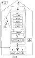
- FIG. 1A and FIG. 1B illustrating example embodiments of a user interface apparatus 110 for controlling a marine vessel 100 by a user 160.
- the user 160 may be a mariner navigating the marine vessel 100 or assisting as a crewmember: a captain, a navigating officer, an officer, an officer of the watch, a helmsman, or other deck crew member, or even a pilot.
- the user 160 may navigate the marine vessel 100 in real-time onboard, or the user 160 may be outside of the marine vessel 100, whereby the user 160 is able to remote control the marine vessel 100 (which may then an unmanned or autonomous ship).
- the manoeuvring may also be non-real-time meaning that the user 160 may plan tricky passages in advance before the actual passage.
- the user interface apparatus 110 may be a stationary apparatus located in a bridge of the marine vessel 100, or the user interface apparatus 120 may also be a mobile computing device (such as placed on a mobile platform, like on a desk, for example).
- the user interface apparatus 110 is for manoeuvring the marine vessel 100, and it may interact with numerous systems including a navigation system 140 (which may comprise an autopilot, a gyrocompass, a magnetic compass, inertial measurement units, a sensor fusion -based speedlog, a satellite positioning receiver of a Global Navigation Satellite System including GPS, Glonass, Galileo or Beidou, etc.), one or more displays 122, a steering system 142 configured to steer the marine vessel 100, and a propulsion system 144 configured to propel the marine vessel 100.
- a navigation system 140 which may comprise an autopilot, a gyrocompass, a magnetic compass, inertial measurement units, a sensor fusion -based speedlog, a satellite positioning receiver of a Global Navigation Satellite System including GPS, Glonass, Galileo or Beidou, etc.
- a navigation system 140 which may comprise an autopilot, a gyrocompass, a magnetic compass, iner
- the interaction may be through a control system 146 (which may be a bridge control system or a remote control system, or another system providing an integrated access to the various subsystems 140, 142, 144) as in FIG. 1A .
- a control system 146 which may be a bridge control system or a remote control system, or another system providing an integrated access to the various subsystems 140, 142, 144) as in FIG. 1A .
- the marine vessel 100 may comprise numerous other systems (such as a radar system) not described here.
- the steering system 142 and the propulsion system 144 may comprise many subsystems, and they may be integrated at least to some degree: diesel engines, electric motors, frequency converters, electric power sources, propellers, rudders, a stern thruster, a tunnel (or bow) thruster 422, active stabilizer fins, etc.
- the steering system 142 and the propulsion system 144 comprises one or more electric podded azimuth thrusters (such as Azipod ® ), which may be rotated full 360 degrees and operated in pulling and/or pushing operation modes.
- the user interface apparatus 110 is configured to receive commands from a user 160, and the one or more displays 122 are configured to show data of the marine vessel 100 to the user 160.
- the one or more displays 122 may be implemented with various technologies, such as projected on a window (like in a head-up display, see WO 2013/174673 ), as a stationary monitor, as a touchscreen 106, or as a part of a mobile platform, for example.
- the user interface apparatus 110 comprises three mechanical elements configured to interact with a user 160: a mechanical stick 112, a mechanical block 114, and a mechanical ring 116.
- the user interface apparatus 110 also comprises one or more processors 132 configured to control operations of the user interface apparatus 110.
- the one or more processors 132 may be implemented with one or more microprocessors 132, and one or more memories 134 including computer program code 136.
- the one or more memories 134 and the computer program code 136 are configured to, with the one or more processors 132 cause performance of the data processing operations.
- the parts 132, 134, 136 may belong to one or more computers 130, or they may belong to specific hardware implementing driver firmware for the user interface apparatus 110, for example.
- the term 'processor' 132 refers to a device that is capable of processing data.
- the apparatus 110 may comprise several processors 132 such as parallel processors, a multicore processor, or a computing environment that simultaneously utilizes resources from several physical computer units (sometimes these are referred as cloud, fog or virtualized computing environments).
- processors 132 such as parallel processors, a multicore processor, or a computing environment that simultaneously utilizes resources from several physical computer units (sometimes these are referred as cloud, fog or virtualized computing environments).
- the processor 132 and the memory 134 may be implemented by an electronic circuitry.
- a non-exhaustive list of implementation techniques for the processor 132 and the memory 134 includes, but is not limited to: logic components, standard integrated circuits, application-specific integrated circuits (ASIC), system-on-a-chip (SoC), application-specific standard products (ASSP), microprocessors, microcontrollers, digital signal processors, special-purpose computer chips, field-programmable gate arrays (FPGA), and other suitable electronics structures.
- ASIC application-specific integrated circuits
- SoC system-on-a-chip
- ASSP application-specific standard products
- microprocessors microcontrollers
- digital signal processors special-purpose computer chips
- FPGA field-programmable gate arrays
- the working memory and the non-volatile memory may be implemented by a random-access memory (RAM), dynamic RAM (DRAM), static RAM (SRAM), a flash memory, a solid state disk (SSD), PROM (programmable read-only memory), a suitable semiconductor, or any other means of implementing an electrical computer memory.
- the computer program code 136 may be implemented by software.
- the software may be written by a suitable programming language, and the resulting executable code may be stored in the memory 134 and run by the processor 132.
- An example embodiment provides a computer-readable medium 138 storing computer program code 136, which, when loaded into the one or more processors 132 and executed by one or more processors 132, causes the one or more processors 132 to perform a computer-implemented method for controlling the user interface apparatus 110, which will be explained with reference to FIG. 1B .
- the computer-readable medium 138 may comprise at least the following: any entity or device capable of carrying the computer program code 136 to the one or more processors 132, a record medium, a computer memory, a read-only memory, an electrical carrier signal, a telecommunications signal, and a software distribution medium. In some jurisdictions, depending on the legislation and the patent practice, the computer-readable medium 138 may not be the telecommunications signal.
- the computer-readable medium 138 may be a computer-readable storage medium.
- the computer-readable medium 138 may be a non-transitory computer-readable storage medium.
- an external computer server such as the control system
- an on shore server 148 may augment the processing: complicated calculations may be performed in the server 146, 148, the server may maintain navigational charts, the server may contain a virtual representation of the marine vessel 100, etc.
- the server 146, 148 may be a networked computer server, which interoperates with the one or more processors 132 according to a client-server architecture, a cloud computing architecture, a peer-to-peer system, or another applicable computing architecture.
- the user interface apparatus 110 may comprise a wireless transceiver, utilizing a suitable communication technology such as GSM, GPRS, EGPRS, WCDMA, UMTS, 3GPP, IMT, LTE, LTE-A, 2G/3G/4G/5G, etc. and/or a suitable non-cellular communication technology such as a proprietary/standard radio technology.
- a suitable communication technology such as GSM, GPRS, EGPRS, WCDMA, UMTS, 3GPP, IMT, LTE, LTE-A, 2G/3G/4G/5G, etc.
- a suitable non-cellular communication technology such as a proprietary/standard radio technology.
- processing may also be provided by another system of the marine vessel 100.
- the steering system 142 and the propulsion system 144 may pre-process the data related to its operation and offer an interface to exchange data with the one or more processors 132 of the user interface apparatus 110.
- the communication couplings between various actors 110, 122, 140, 142, 144, 146, 148 may be implemented with appropriate wired/wireless communication technologies and standard/proprietary protocols.
- the wired communication is implemented with a suitable communication technology utilizing coaxial cable, twisted pair or fibre optic such as LAN (Local Area Network) or the Ethernet.
- the wireless communication is implemented with a suitable radio communication technology such as Bluetooth, Wi-Fi or WLAN (Wireless Local Area Network).
- the operations 150, 152, 154, 156 of the method for controlling the user interface apparatus 110 are not necessarily in a chronological order, and some of the operations may be performed simultaneously or in an order differing from the given ones. Other functions may also be executed between the operations or within the operations and other data exchanged between the operations. Some of the operations or part of the operations may also be left out or replaced by a corresponding operation or a part of the operation. It should be noted that no special order of operations is required, except where necessary due to the logical requirements for the processing order.
- the method starts after the one or more processors 132 are switched on, and continues until a reset or a switch off of the one or more processors 132.
- the mechanical stick 112 is configured to set a 154 control parameter by a linear motion
- the mechanical block 114 is configured to set 154 a control parameter by a rotational motion
- the mechanical ring 116 is configured to set 154 a control parameter by a rotational motion.
- one or more electric motors 118 are configured to give tactile feedback related to setting 154 a control parameter
- one or more electric visual elements 120 are configured to give visual feedback related to setting 154 a control parameter.
- the one or more processors 132 are configured to select a control parameter from among two or more control parameters 164A, 168A, 164B, 168B.
- the selection 150 may be made by a user interface operation, such as the user 160 pressing a button (located in the same place as an illumination 200) on the end of the mechanical stick 112.
- the selection 150 may be automatic, such as made by the processor 132 or the control system 146 to fit the navigation circumstances (such as speed and/or location) of the marine vessel 100.
- the one or more processors 132 are configured to retrieve distinct settings 166A/170A/166B/170B for the tactile feedback and/or the visual feedback based on the selected control parameter.
- the one or more processors 132 are configured to control the tactile feedback given by the one or more electric motors 118 and/or the visual feedback given by the one or more electric visual elements 120 during setting the selected control parameter in 154. As shown in the drawings, both the tactile feedback and the visual feedback are in general given, but for a certain control parameter in a certain operating situation only visual feedback or tactile feedback may be given.
- the functioning of the user interface apparatus 110 may be controlled.
- the control parameter may be selected from a plurality of control parameters
- the user interface apparatus 110 may offer an integrated control approach: the distinct tactile (or haptic force) and visual feedback settings enable setting different control parameters with the same mechanical elements 112, 114, 116. This is useful when navigating as the mariner 160 may then concentrate on using the single user interface apparatus 110 and the one or more displays 122, instead of having to observe and use a multitude of various separate control apparatuses spread around the bridge of the ship 100.
- the single user interface apparatus 110 makes it easier to sense the cause and impact of the control commands given by the user 160 and hence improve the situational awareness.
- the user interface apparatus 110 may be used in different kinds of marine vessels and for different operation situations such as auto pilot, open sea, manoeuvring, fairway, docking, etc. Besides tactile and visual feedback, also audio feedback may be controlled and given by the user interface apparatus 110.
- the mariner 160 may adjust the control parameters, which may then be inputted to the steering system 142 and the propulsion system 144.
- the control parameters may comprise operation parameters of the steering system 142 and the propulsion system 144, including, but not limited to a rudder angle, a propeller angle, a propeller speed, a propeller torque, a propeller power, a propeller pitch, a propeller thrust, an azimuth thruster angle, an azimuth thruster speed, an azimuth thruster torque, an azimuth thruster power, an azimuth thruster pitch, an azimuth thruster thrust, an electric podded azimuth thruster angle, an electric podded azimuth thruster speed, an electric podded azimuth thruster torque, an electric podded azimuth thruster power, an electric podded azimuth thruster pitch, an electric podded azimuth thruster thrust, etc.
- the one or more processors 132 are configured to maintain two or more of the following control parameters for the mechanical stick 112: a ship speed, a thrust force, a propeller speed, a propeller pitch, a power output.
- the one or more processors 132 are configured to maintain two or more of the following control parameters for the mechanical block 114: a direction of a thrust force, a steering angle.
- the one or more processors 132 are configured to maintain two or more of the following control parameters for the mechanical ring 116: a heading, a course, a torque, a rate of turn, a steering angle.
- FIG. 2 illustrates an example embodiment of the user interface apparatus 110, wherein the mechanical stick 112, the mechanical block 114, and the mechanical ring 116 are configured and positioned concentric.
- This may offer the advantage that the user 160 intuitively knows the relations of the various control parameters as they are in the same space: the neutral position of the mechanical stick 112 is in a dead centre, and the mechanical block 114 and the mechanical ring 116 rotate around the dead centre.
- the mechanical stick 112 and the mechanical block 114 are configured to adjust control parameters from the point of view of the center (such as a control point or a center of rotation) of the marine vessel 100, whereas the mechanical ring 116 is configured to adjust control parameters around the center of the marine vessel 100.
- FIG. 2 also illustrates an example embodiment, wherein the mechanical stick 112 is configured and positioned to move along the linear motion across the mechanical block 114.
- the mechanical block 114 may comprise an external dome shape 210 (see also FIG. 3 : 210A, 210B).
- the dome shape 210 may be truncated, i.e., it may have vertical sides 212 (see also FIG. 3 : 212A, 212B).
- the mechanical stick 112 may have a base 202 with a graded scale moving in unison with the mechanical stick along the surface of the dome shape 210 (or the base 202 may move in a hollow of the dome shape 202)
- the mechanical ring 116 is configured and positioned to surround the mechanical block 114, whereas in an alternative example embodiment of FIG. 3 , the mechanical ring 116 may be placed in the vicinity of the combination of the mechanical stick 112 and the mechanical block 114.
- An advantage of using the mechanical ring 116 is that its manipulation with a great accuracy is possible: the user 160 may rotate the mechanical ring 116 with precision and also observe the amount of rotation easily.
- the rate of adjustment may be changeable. For example, in a default configuration, one full turn of the mechanical ring 116 is equivalent to an adjustment of 360 degrees, whereas in a special configuration, one full turn only adjusts 36 degrees, i.e., ten full turns being equivalent to the adjustment of 360 degrees.
- the mechanical ring 116 may be provided with a graded scale: large ridges 220 dividing the mechanical ring into four 90 degrees sectors, smaller ridges 224 denoting 30 degrees, and smallest ridges denoting 10 degrees.
- the one or more visual elements 120, 120A, 120B comprise a plurality of leds configured to give the visual feedback for the selected control parameter as one or more of an allowed range, a current setting, a new setting.
- FIG. 4 illustrates the visual element 120A with leds 400, 402 placed on both sides of the trajectory of the mechanical stick 112.
- a graded scale of the base 202 of the mechanical stick 112 may comprise visual elements such as an illumination.
- FIG. 5 illustrates the visual element 120B with leds 500, 502 placed around the mechanical block 114.
- the one or more visual elements may also comprise an illumination 200 (with a led, for example) in the end of the mechanical stick 112.
- Other illumination may also be present, such as illuminated sections 230, 232 (with leds, for example).
- the one or more electric motors 118 are configured to give the tactile feedback for the selected control parameter as one or more of detents, varying degrees of friction, restraints.
- the combined tactile and visual feedback of the single user interface apparatus 110 improves the situational awareness, because the feedback indicates both reference and actual impact of the command so that the immediate indication of the impact does not need to be observed from scattered user interfaces.
- FIG. 6A and FIG. 6B illustrate an example embodiment of such tactile feedback given while operating the mechanical stick 112.
- the mechanical stick 112 is in the neutral position, and a detent 602 is felt when trying to move the mechanical stick 112 in the linear motion direction 600.
- the detent 602 feels like an inertia, i.e., the mechanical stick 112 tries to remain in the neutral position.
- FIG. 6B the user 160 has pulled the mechanical stick 112 to reverse with 50% power, as shown by an index at the detent 606.
- the restraint 610, 612 feels like a stop, i.e., the mechanical stick 112 cannot be moved past the stop.
- FIG. 6A also show an example embodiment of varying degrees of friction: when the mechanical stick 112 is moved in the region 620, a lighter friction is felt, whereas when the mechanical stick 112 is moved in either region 622 or 624, a harder friction is felt. This way, the user 160 may move the mechanical stick 112 within the power range of 30% forward or reverse lighter than in the remaining maximum power range of 70% forward or reverse.
- the one or more electric motors 118 may also give tactile feedback as a spring force: if the user 160 exceeds an allowed range or limit, the one or more electric motors 118 are configured to bounce the mechanical element 112/114/116 back to an allowed range or back to the limit.
- the one or more processors 132 are configured to operate the user interface apparatus in a plurality of operation modes 160A, 160B, and retrieve 152 the distinct settings as a part of a distinct configuration 162A, 162B of an operation mode 160A, 160B.
- the distinct configuration 162A, 162B maps the selected control parameter to one of the mechanical stick 112, the mechanical block 114, and the mechanical ring 116.
- N, M and K are positive integers greater than one.
- the distinct settings 166A, 170A, 166B, 170B may be stored in the memory 134, or they may be stored in the server 146, 148, or they may even be hardcoded as parameters in the computer program code 136 or its configuration file.
- the one or more processors 132 are configured to operate the user interface apparatus in an auto pilot control mode, wherein the one or more processors 132 are configured to maintain a control parameter settable 154 with the mechanical stick 112 related to a ship speed, disable the mechanical block 114, and maintain control parameters settable 154 with the mechanical ring 116 related to one or more of a heading, a course.
- the illuminations 200, 230, 232 indicate to the user 160 that the auto pilot control mode is on.
- FIG. 7B illustrates that in the auto pilot control mode, the present setting of the speed control may be shown, and also the heading/course. This is achieved by moving the mechanical stick 112 and the mechanical ring 116 to appropriate positions with the one or more electric motors 118.
- the one or more processors 132 are configured to operate the user interface apparatus in an azimuth lever mode, wherein the one or more processors 132 are configured to maintain control parameters settable 154 with the mechanical stick 112 related to one or more of a thrust force, a propeller speed, maintain a control parameter settable 154 with the mechanical block 114 related to a direction of a thrust force, and disable the mechanical ring 116.
- the one or more processors 132 are configured to operate the user interface apparatus in an azimuth lever mode, wherein the one or more processors 132 are configured to maintain control parameters settable 154 with the mechanical stick 112 related to one or more of a thrust force, a propeller speed, maintain a control parameter settable 154 with the mechanical block 114 related to a direction of a thrust force, and disable the mechanical ring 116.
- the propeller speed is set to 50% forward of the maximum rotations per minute with the mechanical stick 112 as indicated with the illuminated leds 802, 804, and the angle of the azimuthing propulsion units is set to 10 degrees in the port side direction with the mechanical block 114 as indicated with the illuminated leds 806, 808.
- the propeller speed is set to 50% reverse of the maximum rotations per minute with the mechanical stick 112 as indicated with the illuminated leds 810, 812, and the angle of the azimuthing propulsion units is set to 10 degrees in the starboard side direction with the mechanical block 114 as indicated with the illuminated leds 814, 816.
- the one or more processors 132 are configured to operate the user interface apparatus in a bow thruster mode (or bow/stern thruster mode, or any fixed direction thruster mode), wherein the one or more processors 132 are configured to maintain control parameters settable 154 with the mechanical stick 112 related to one or more of a thrust, a speed, disable the mechanical block 114, and disable the mechanical ring 116.
- the speed is set to 50% in the port side direction with the mechanical stick 112 as indicated with the illuminated leds 230, 232, 900, 902, 904, 906, 908, 910.
- the speed is set to 50% in the starboard side direction with the mechanical stick 112 as indicated with the illuminated leds 230, 232, 900, 902, 904, 906, 912, 914.
- the one or more processors 132 are configured to operate the user interface apparatus in a mini wheel mode, wherein the one or more processors 132 are configured to maintain control parameters settable 154 with the mechanical stick 112 related to one or more of a ship speed, a propeller speed, disable the mechanical block 114, and maintain a control parameter settable 154 with the mechanical ring 116 related to a steering angle.
- the steering angle is set to 5 degrees in the starboard side direction with the mechanical block 114 as indicated with the illuminated leds 230, 232, 1000, 1002, 1004, 1006, 1008, 1010.
- the propeller speed is set to 50% forward with the mechanical stick 112 as indicated with the further illuminated leds 1030, 1032.
- the one or more processors 132 are configured to operate the user interface apparatus in a joystick mode, wherein the one or more processors 132 are configured to maintain control parameters settable 154 with the mechanical stick 112 related to one or more of a ship speed, a thrust force, a power, maintain a control parameter settable 154 with the mechanical block 114 related to a direction of a thrust force, and maintain control parameters settable 154 with the mechanical ring 116 related to one or more of a torque, a rate of turn.
- the rate of turn per minutes is 30 degrees as indicated with the illuminated leds 1100, 1102.
- FIG. 11A the rate of turn per minutes is 30 degrees as indicated with the illuminated leds 1100, 1102.
- the thrust force is set to 25% forward with the mechanical stick 112 as indicated with the illuminated leds 200, 230, 232, 1108, 1110, and the set point is set with the mechanical block 114 to the direction indicated with the illuminated led 1104, whereas the actual movement direction is indicated with the illuminated led 1106.
- FIG. 11C shows the settings 230, 232,1104, 1108, 1110, the actual movement direction 1106, and the rate of turn 1100, 1102.
Landscapes
- Engineering & Computer Science (AREA)
- General Engineering & Computer Science (AREA)
- Theoretical Computer Science (AREA)
- Physics & Mathematics (AREA)
- General Physics & Mathematics (AREA)
- Human Computer Interaction (AREA)
- Mechanical Engineering (AREA)
- Chemical & Material Sciences (AREA)
- Combustion & Propulsion (AREA)
- Ocean & Marine Engineering (AREA)
- Automation & Control Theory (AREA)
- User Interface Of Digital Computer (AREA)
- Mechanical Control Devices (AREA)
Claims (10)
- Appareil d'interface utilisateur (110) pour commander un vaisseau marin (100), comprenant :un levier mécanique (112) configuré pour régler (154) un premier paramètre de commande par un mouvement linéaire ;un bloc mécanique (114) configuré pour régler (154) un second paramètre de commande par un mouvement de rotation ;un ou plusieurs moteurs électriques (118) configurés pour donner une rétroaction tactile associée au réglage (154) du premier paramètre de commande et/ou du second paramètre de commande ; etun ou plusieurs éléments visuels électriques (120, 120A, 120B) configurés pour donner une rétroaction visuelle associée au réglage (154) du premier paramètre de commande et/ou du second paramètre de commande ;caractérisé en ce que l'appareil d'interface utilisateur (110) comprend en outre :une bague mécanique (116) configurée pour régler (154) un troisième paramètre de commande par un mouvement de rotation, dans lequel le levier mécanique (112), le bloc mécanique (114), et la bague mécanique (116) sont configurés et positionnés de manière concentrique ; etun ou plusieurs processeurs (132) configurés pour :actionner l'appareil d'interface utilisateur (110) dans un mode de fonctionnement (160A) d'une pluralité de modes de fonctionnement (160A, 160B) ;sélectionner (150) chacun du premier paramètre de commande, du second paramètre de commande, et du troisième paramètre de commande parmi deux, ou plus, paramètres de commande (164A, 168A, 164B, 168B) en fonction d'une configuration distincte (162A, 162B) du mode de fonctionnement (160A), dans lequel les deux, ou plus, paramètres de commande pour le premier paramètre de commande comprennent deux, ou plus, d'une vitesse de navire, d'une force de poussée, d'une vitesse d'hélice, d'un pas d'hélice, et d'une sortie de puissance, les deux, ou plus, paramètres de commande pour le second paramètre de commande comprennent deux, ou plus, d'une direction d'une force de poussée, d'un angle de braquage, et d'une désactivation du bloc mécanique, et les deux, ou plus, paramètres de commande pour le troisième paramètre de commande comprennent deux, ou plus, d'un cap, d'une trajectoire, d'un couple, d'une vitesse de giration, d'un angle de braquage, et d'une désactivation de la bague mécanique ;récupérer (152) des réglages distincts (166A/170A/166B/170B) comme une partie de la configuration distincte (162A, 162B) du mode de fonctionnement (160A) pour la rétroaction tactile et/ou la rétroaction visuelle en fonction du premier paramètre de commande, du second paramètre de commande, et du troisième paramètre de commande ; etcommander (156) la rétroaction tactile donnée par les un ou plusieurs moteurs électriques (118) et/ou la rétroaction visuelle donnée par les un ou plusieurs éléments visuels électriques (120) pendant le réglage (154) d'un ou plusieurs du premier paramètre de commande, du second paramètre de commande, et du troisième paramètre de commande.
- Appareil selon la revendication 1, dans lequel le levier mécanique (112) est configuré et positionné pour se déplacer le long du mouvement linéaire sur le bloc mécanique (114), et le bloc mécanique (114) comprend une forme de dôme externe (210).
- Appareil selon l'une quelconque des revendications précédentes, dans lequel la bague mécanique (116) est configurée et positionnée pour entourer le bloc mécanique (114).
- Appareil selon l'une quelconque des revendications précédentes, dans lequel les un ou plusieurs éléments visuels (120, 120A, 120B) comprennent une pluralité de DEL (400, 402, 500, 502) configurées pour donner la rétroaction visuelle pour un ou plusieurs du premier paramètre de commande, du second paramètre de commande, et du troisième paramètre de commande comme un ou plusieurs d'une plage autorisée, d'un paramètre actuel, et d'un nouveau paramètre.
- Appareil selon l'une quelconque des revendications précédentes, dans lequel les un ou plusieurs moteurs électriques (118) sont configurés pour donner la rétroaction tactile pour un ou plusieurs du premier paramètre de commande, du second paramètre de commande, et du troisième paramètre de commande comme un ou plusieurs de détentes (602, 604, 606, 608), de degrés de frottement variables (620, 622, 624), et de retenues (610, 612) .
- Appareil selon l'une quelconque des revendications précédentes, dans lequel les un ou plusieurs processeurs (132) sont configurés pour actionner l'appareil d'interface utilisateur dans un mode de commande autopilote comme mode de fonctionnement (160A), dans lequel les un ou plusieurs processeurs (132) sont configurés pour conserver le premier paramètre de commande réglable (154) avec le levier mécanique (112) associé à la vitesse de navire, conserver le second paramètre de commande pour désactiver le bloc mécanique (114), et conserver le troisième paramètre de commande réglable (154) avec la bague mécanique (116) associée à l'un ou plusieurs du cap, et de la trajectoire.
- Appareil selon l'une quelconque des revendications précédentes, dans lequel les un ou plusieurs processeurs (132) sont configurés pour actionner l'appareil d'interface utilisateur dans un mode de levier azimut comme mode de fonctionnement (160B), dans lequel les un ou plusieurs processeurs (132) sont configurés pour conserver le premier paramètre de commande réglable (154) avec le levier mécanique (112) associé à l'un ou plusieurs de la force de poussée, et de la vitesse d'hélice, conserver le second paramètre de commande réglable (154) avec le bloc mécanique (114) associé à la direction de la force de poussée, et conserver le troisième paramètre de commande pour désactiver la bague mécanique (116).
- Appareil selon l'une quelconque des revendications précédentes, dans lequel les un ou plusieurs processeurs (132) sont configurés pour actionner l'appareil d'interface utilisateur dans un mode de propulseur d'étrave comme mode de fonctionnement (160B), dans lequel les un ou plusieurs processeurs (132) sont configurés pour conserver le premier paramètre de commande réglable (154) avec le levier mécanique (112) associé à l'un ou plusieurs de la poussée, et de la vitesse, conserver le second paramètre de commande pour désactiver le bloc mécanique (114), et conserver le troisième paramètre de commande pour désactiver la bague mécanique (116).
- Appareil selon l'une quelconque des revendications précédentes, dans lequel les un ou plusieurs processeurs (132) sont configurés pour actionner l'appareil d'interface utilisateur dans un mode de rotation minimale comme mode de fonctionnement (160B), dans lequel les un ou plusieurs processeurs (132) sont configurés pour conserver le premier paramètre de commande réglable (154) avec le levier mécanique (112) associé à l'un ou plusieurs de la vitesse de navire, et de la vitesse d'hélice, conserver le second paramètre de commande pour désactiver le bloc mécanique (114), et conserver le troisième paramètre de commande réglable (154) avec la bague mécanique (116) associée à l'angle de braquage.
- Appareil selon l'une quelconque des revendications précédentes, dans lequel les un ou plusieurs processeurs (132) sont configurés pour actionner l'appareil d'interface utilisateur dans un mode de levier de commande comme mode de fonctionnement (160B), dans lequel les un ou plusieurs processeurs (132) sont configurés pour conserver le premier paramètre de commande réglable (154) avec le levier mécanique (112) associé à l'un ou plusieurs de la vitesse de navire, de la force de poussée, et de la puissance, conserver le second paramètre de commande réglable (154) avec le bloc mécanique (114) associé à la direction de la force de poussée, et conserver le troisième paramètre de commande réglable (154) avec la bague mécanique (116) associée à l'un ou plusieurs du couple, et de la vitesse de giration.
Priority Applications (7)
| Application Number | Priority Date | Filing Date | Title |
|---|---|---|---|
| EP19165678.4A EP3716015B1 (fr) | 2019-03-28 | 2019-03-28 | Appareil d'interface utilisateur pour commander un vaisseau marin |
| US17/593,784 US20220126971A1 (en) | 2019-03-28 | 2020-03-27 | User Interface Apparatus For Controlling Marine Vessel |
| SG11202110586VA SG11202110586VA (en) | 2019-03-28 | 2020-03-27 | User interface apparatus for controlling marine vessel |
| JP2021557205A JP7377281B2 (ja) | 2019-03-28 | 2020-03-27 | 船舶を制御するためのユーザ・インターフェース装置 |
| PCT/EP2020/058727 WO2020193756A1 (fr) | 2019-03-28 | 2020-03-27 | Appareil d'interface utilisateur permettant de commander un navire marin |
| CN202080039059.5A CN113906369B (zh) | 2019-03-28 | 2020-03-27 | 用于控制海洋船舶的用户接口设备 |
| KR1020217034469A KR102506911B1 (ko) | 2019-03-28 | 2020-03-27 | 해양 선박 제어용 사용자 인터페이스 장치 |
Applications Claiming Priority (1)
| Application Number | Priority Date | Filing Date | Title |
|---|---|---|---|
| EP19165678.4A EP3716015B1 (fr) | 2019-03-28 | 2019-03-28 | Appareil d'interface utilisateur pour commander un vaisseau marin |
Publications (2)
| Publication Number | Publication Date |
|---|---|
| EP3716015A1 EP3716015A1 (fr) | 2020-09-30 |
| EP3716015B1 true EP3716015B1 (fr) | 2022-10-12 |
Family
ID=66349234
Family Applications (1)
| Application Number | Title | Priority Date | Filing Date |
|---|---|---|---|
| EP19165678.4A Active EP3716015B1 (fr) | 2019-03-28 | 2019-03-28 | Appareil d'interface utilisateur pour commander un vaisseau marin |
Country Status (7)
| Country | Link |
|---|---|
| US (1) | US20220126971A1 (fr) |
| EP (1) | EP3716015B1 (fr) |
| JP (1) | JP7377281B2 (fr) |
| KR (1) | KR102506911B1 (fr) |
| CN (1) | CN113906369B (fr) |
| SG (1) | SG11202110586VA (fr) |
| WO (1) | WO2020193756A1 (fr) |
Families Citing this family (1)
| Publication number | Priority date | Publication date | Assignee | Title |
|---|---|---|---|---|
| US20240025528A1 (en) * | 2022-07-20 | 2024-01-25 | Brunswick Corporation | Marine propulsion system and joystick control method |
Family Cites Families (14)
| Publication number | Priority date | Publication date | Assignee | Title |
|---|---|---|---|---|
| DE3222054A1 (de) * | 1982-06-11 | 1983-12-15 | Schottel-Werft Josef Becker Gmbh & Co Kg, 5401 Spay | Vorrichtung zum vorgeben der bewegungsrichtung und kraft eines wasserfahrzeugs |
| JP4019169B2 (ja) * | 2001-10-04 | 2007-12-12 | ヤマハマリン株式会社 | 船舶推進機のエンジン制御装置 |
| US9274528B2 (en) * | 2005-06-23 | 2016-03-01 | Marine 1, Llc | Marine vessel control system |
| US7766910B2 (en) * | 2006-01-24 | 2010-08-03 | Tyco Healthcare Group Lp | Vessel sealer and divider for large tissue structures |
| US8174512B2 (en) * | 2006-06-02 | 2012-05-08 | Immersion Corporation | Hybrid haptic device utilizing mechanical and programmable haptic effects |
| CN102171095B (zh) * | 2008-10-02 | 2015-07-15 | Zf腓德烈斯哈芬股份公司 | 操纵杆控制的船用操纵系统 |
| US9008973B2 (en) * | 2009-11-09 | 2015-04-14 | Barry French | Wearable sensor system with gesture recognition for measuring physical performance |
| EP2666709A1 (fr) | 2012-05-25 | 2013-11-27 | ABB Research Ltd. | Navire possédant une fenêtre en tant qu'interface utilisateur informatique |
| EP3006327B1 (fr) * | 2014-10-06 | 2018-05-16 | ABB Schweiz AG | Système de commande pour un navire |
| EP3048038A1 (fr) * | 2015-01-26 | 2016-07-27 | ABB Oy | Commande d'unité de propulsion |
| US10000268B1 (en) * | 2015-08-20 | 2018-06-19 | Brunswick Corporation | Systems and methods for controlling a marine vessel having a joystick with adjustable display |
| CN106054884B (zh) * | 2016-06-16 | 2018-12-07 | 哈尔滨工程大学 | 基于神经网络的l1自适应船舶动力定位双环控制系统 |
| US9827811B1 (en) * | 2016-07-14 | 2017-11-28 | Toyota Motor Engineering & Manufacturing North America, Inc. | Vehicular haptic feedback system and method |
| EP3335978A1 (fr) * | 2016-12-14 | 2018-06-20 | Caterpillar Propulsion Production AB | Levier de commande de propulseur azimutal |
-
2019
- 2019-03-28 EP EP19165678.4A patent/EP3716015B1/fr active Active
-
2020
- 2020-03-27 KR KR1020217034469A patent/KR102506911B1/ko active IP Right Grant
- 2020-03-27 WO PCT/EP2020/058727 patent/WO2020193756A1/fr active Application Filing
- 2020-03-27 JP JP2021557205A patent/JP7377281B2/ja active Active
- 2020-03-27 US US17/593,784 patent/US20220126971A1/en active Pending
- 2020-03-27 CN CN202080039059.5A patent/CN113906369B/zh active Active
- 2020-03-27 SG SG11202110586VA patent/SG11202110586VA/en unknown
Also Published As
| Publication number | Publication date |
|---|---|
| JP7377281B2 (ja) | 2023-11-09 |
| EP3716015A1 (fr) | 2020-09-30 |
| SG11202110586VA (en) | 2021-10-28 |
| US20220126971A1 (en) | 2022-04-28 |
| CN113906369B (zh) | 2023-12-01 |
| KR20210141685A (ko) | 2021-11-23 |
| CN113906369A (zh) | 2022-01-07 |
| KR102506911B1 (ko) | 2023-03-08 |
| JP2022526930A (ja) | 2022-05-27 |
| WO2020193756A1 (fr) | 2020-10-01 |
Similar Documents
| Publication | Publication Date | Title |
|---|---|---|
| AU2009298414B2 (en) | Joystick controlled marine maneuvering system | |
| US9594375B2 (en) | Heading control using multiple autopilots | |
| EP3214522A1 (fr) | Dispositif et méthode pour le pilotage d'un bateau | |
| US8924054B1 (en) | Systems and methods for positioning a marine vessel | |
| EP1448436B1 (fr) | Systeme de telecommande pour vehicule | |
| US20160246300A1 (en) | Multiple Autopilot Interface | |
| EP3170735B1 (fr) | Procédé de commande de manoeuvre de bateau pour bateau et bateau équipé d'un système de commande de manoeuvre pour bateau | |
| EP3198349B1 (fr) | Retour d'informations tactile pour contraintes de trajectoire en temps réel | |
| EP3627106A2 (fr) | Appareil et procédé permettant de man uvrer un vaisseau marin | |
| US20220374015A1 (en) | Marine vessel propulsion control system and marine vessel | |
| EP3716015B1 (fr) | Appareil d'interface utilisateur pour commander un vaisseau marin | |
| US9594374B2 (en) | Operating multiple autopilots | |
| US10953973B2 (en) | Ship handling device and ship including the same | |
| JP6532507B2 (ja) | 一軸二舵船の操舵制御装置 | |
| CA2773702C (fr) | Systeme de commande pour vehicules | |
| US11573087B1 (en) | Boat maneuvering control method for boat and boat maneuvering control system for boat | |
| Wakabayashi et al. | Tablet Control System for Offshore Support and Research Vessel—Development, Implementation, and Operational Testing— | |
| EP4306406A1 (fr) | Dispositif de manoeuvre de navire et navire | |
| US20230312072A1 (en) | System for and method of controlling watercraft | |
| Battipede et al. | Innovative Piloting Technique for a Semi-Autonomous UAV Lighter-Than-Air Platform Simulator | |
| Leavitt | DYNAMIC POSITIONING CONFERENCE October 13-14, 2009 New Applications |
Legal Events
| Date | Code | Title | Description |
|---|---|---|---|
| PUAI | Public reference made under article 153(3) epc to a published international application that has entered the european phase |
Free format text: ORIGINAL CODE: 0009012 |
|
| STAA | Information on the status of an ep patent application or granted ep patent |
Free format text: STATUS: THE APPLICATION HAS BEEN PUBLISHED |
|
| AK | Designated contracting states |
Kind code of ref document: A1 Designated state(s): AL AT BE BG CH CY CZ DE DK EE ES FI FR GB GR HR HU IE IS IT LI LT LU LV MC MK MT NL NO PL PT RO RS SE SI SK SM TR |
|
| AX | Request for extension of the european patent |
Extension state: BA ME |
|
| STAA | Information on the status of an ep patent application or granted ep patent |
Free format text: STATUS: REQUEST FOR EXAMINATION WAS MADE |
|
| 17P | Request for examination filed |
Effective date: 20210324 |
|
| RBV | Designated contracting states (corrected) |
Designated state(s): AL AT BE BG CH CY CZ DE DK EE ES FI FR GB GR HR HU IE IS IT LI LT LU LV MC MK MT NL NO PL PT RO RS SE SI SK SM TR |
|
| GRAP | Despatch of communication of intention to grant a patent |
Free format text: ORIGINAL CODE: EPIDOSNIGR1 |
|
| STAA | Information on the status of an ep patent application or granted ep patent |
Free format text: STATUS: GRANT OF PATENT IS INTENDED |
|
| RIC1 | Information provided on ipc code assigned before grant |
Ipc: B63H 25/02 20060101ALN20220429BHEP Ipc: G06F 3/04847 20220101ALI20220429BHEP Ipc: G05G 1/04 20060101ALI20220429BHEP Ipc: B63H 21/21 20060101ALI20220429BHEP Ipc: G06F 3/0484 20130101ALI20220429BHEP Ipc: G06F 3/0362 20130101ALI20220429BHEP Ipc: G06F 3/0338 20130101ALI20220429BHEP Ipc: G06F 3/01 20060101AFI20220429BHEP |
|
| INTG | Intention to grant announced |
Effective date: 20220525 |
|
| RAP3 | Party data changed (applicant data changed or rights of an application transferred) |
Owner name: ABB SCHWEIZ AG |
|
| GRAS | Grant fee paid |
Free format text: ORIGINAL CODE: EPIDOSNIGR3 |
|
| GRAA | (expected) grant |
Free format text: ORIGINAL CODE: 0009210 |
|
| STAA | Information on the status of an ep patent application or granted ep patent |
Free format text: STATUS: THE PATENT HAS BEEN GRANTED |
|
| AK | Designated contracting states |
Kind code of ref document: B1 Designated state(s): AL AT BE BG CH CY CZ DE DK EE ES FI FR GB GR HR HU IE IS IT LI LT LU LV MC MK MT NL NO PL PT RO RS SE SI SK SM TR |
|
| REG | Reference to a national code |
Ref country code: GB Ref legal event code: FG4D |
|
| REG | Reference to a national code |
Ref country code: CH Ref legal event code: EP |
|
| REG | Reference to a national code |
Ref country code: DE Ref legal event code: R096 Ref document number: 602019020433 Country of ref document: DE |
|
| REG | Reference to a national code |
Ref country code: IE Ref legal event code: FG4D |
|
| REG | Reference to a national code |
Ref country code: AT Ref legal event code: REF Ref document number: 1524556 Country of ref document: AT Kind code of ref document: T Effective date: 20221115 |
|
| REG | Reference to a national code |
Ref country code: LT Ref legal event code: MG9D |
|
| REG | Reference to a national code |
Ref country code: NO Ref legal event code: T2 Effective date: 20221012 |
|
| REG | Reference to a national code |
Ref country code: NL Ref legal event code: MP Effective date: 20221012 |
|
| REG | Reference to a national code |
Ref country code: AT Ref legal event code: MK05 Ref document number: 1524556 Country of ref document: AT Kind code of ref document: T Effective date: 20221012 |
|
| PG25 | Lapsed in a contracting state [announced via postgrant information from national office to epo] |
Ref country code: NL Free format text: LAPSE BECAUSE OF FAILURE TO SUBMIT A TRANSLATION OF THE DESCRIPTION OR TO PAY THE FEE WITHIN THE PRESCRIBED TIME-LIMIT Effective date: 20221012 |
|
| PG25 | Lapsed in a contracting state [announced via postgrant information from national office to epo] |
Ref country code: SE Free format text: LAPSE BECAUSE OF FAILURE TO SUBMIT A TRANSLATION OF THE DESCRIPTION OR TO PAY THE FEE WITHIN THE PRESCRIBED TIME-LIMIT Effective date: 20221012 Ref country code: PT Free format text: LAPSE BECAUSE OF FAILURE TO SUBMIT A TRANSLATION OF THE DESCRIPTION OR TO PAY THE FEE WITHIN THE PRESCRIBED TIME-LIMIT Effective date: 20230213 Ref country code: LT Free format text: LAPSE BECAUSE OF FAILURE TO SUBMIT A TRANSLATION OF THE DESCRIPTION OR TO PAY THE FEE WITHIN THE PRESCRIBED TIME-LIMIT Effective date: 20221012 Ref country code: ES Free format text: LAPSE BECAUSE OF FAILURE TO SUBMIT A TRANSLATION OF THE DESCRIPTION OR TO PAY THE FEE WITHIN THE PRESCRIBED TIME-LIMIT Effective date: 20221012 Ref country code: AT Free format text: LAPSE BECAUSE OF FAILURE TO SUBMIT A TRANSLATION OF THE DESCRIPTION OR TO PAY THE FEE WITHIN THE PRESCRIBED TIME-LIMIT Effective date: 20221012 |
|
| PGFP | Annual fee paid to national office [announced via postgrant information from national office to epo] |
Ref country code: NO Payment date: 20230324 Year of fee payment: 5 Ref country code: FR Payment date: 20230327 Year of fee payment: 5 |
|
| PG25 | Lapsed in a contracting state [announced via postgrant information from national office to epo] |
Ref country code: RS Free format text: LAPSE BECAUSE OF FAILURE TO SUBMIT A TRANSLATION OF THE DESCRIPTION OR TO PAY THE FEE WITHIN THE PRESCRIBED TIME-LIMIT Effective date: 20221012 Ref country code: PL Free format text: LAPSE BECAUSE OF FAILURE TO SUBMIT A TRANSLATION OF THE DESCRIPTION OR TO PAY THE FEE WITHIN THE PRESCRIBED TIME-LIMIT Effective date: 20221012 Ref country code: LV Free format text: LAPSE BECAUSE OF FAILURE TO SUBMIT A TRANSLATION OF THE DESCRIPTION OR TO PAY THE FEE WITHIN THE PRESCRIBED TIME-LIMIT Effective date: 20221012 Ref country code: IS Free format text: LAPSE BECAUSE OF FAILURE TO SUBMIT A TRANSLATION OF THE DESCRIPTION OR TO PAY THE FEE WITHIN THE PRESCRIBED TIME-LIMIT Effective date: 20230212 Ref country code: HR Free format text: LAPSE BECAUSE OF FAILURE TO SUBMIT A TRANSLATION OF THE DESCRIPTION OR TO PAY THE FEE WITHIN THE PRESCRIBED TIME-LIMIT Effective date: 20221012 Ref country code: GR Free format text: LAPSE BECAUSE OF FAILURE TO SUBMIT A TRANSLATION OF THE DESCRIPTION OR TO PAY THE FEE WITHIN THE PRESCRIBED TIME-LIMIT Effective date: 20230113 |
|
| PGFP | Annual fee paid to national office [announced via postgrant information from national office to epo] |
Ref country code: IT Payment date: 20230328 Year of fee payment: 5 |
|
| REG | Reference to a national code |
Ref country code: DE Ref legal event code: R097 Ref document number: 602019020433 Country of ref document: DE |
|
| PG25 | Lapsed in a contracting state [announced via postgrant information from national office to epo] |
Ref country code: SM Free format text: LAPSE BECAUSE OF FAILURE TO SUBMIT A TRANSLATION OF THE DESCRIPTION OR TO PAY THE FEE WITHIN THE PRESCRIBED TIME-LIMIT Effective date: 20221012 Ref country code: RO Free format text: LAPSE BECAUSE OF FAILURE TO SUBMIT A TRANSLATION OF THE DESCRIPTION OR TO PAY THE FEE WITHIN THE PRESCRIBED TIME-LIMIT Effective date: 20221012 Ref country code: EE Free format text: LAPSE BECAUSE OF FAILURE TO SUBMIT A TRANSLATION OF THE DESCRIPTION OR TO PAY THE FEE WITHIN THE PRESCRIBED TIME-LIMIT Effective date: 20221012 Ref country code: DK Free format text: LAPSE BECAUSE OF FAILURE TO SUBMIT A TRANSLATION OF THE DESCRIPTION OR TO PAY THE FEE WITHIN THE PRESCRIBED TIME-LIMIT Effective date: 20221012 Ref country code: CZ Free format text: LAPSE BECAUSE OF FAILURE TO SUBMIT A TRANSLATION OF THE DESCRIPTION OR TO PAY THE FEE WITHIN THE PRESCRIBED TIME-LIMIT Effective date: 20221012 |
|
| PLBE | No opposition filed within time limit |
Free format text: ORIGINAL CODE: 0009261 |
|
| STAA | Information on the status of an ep patent application or granted ep patent |
Free format text: STATUS: NO OPPOSITION FILED WITHIN TIME LIMIT |
|
| PG25 | Lapsed in a contracting state [announced via postgrant information from national office to epo] |
Ref country code: SK Free format text: LAPSE BECAUSE OF FAILURE TO SUBMIT A TRANSLATION OF THE DESCRIPTION OR TO PAY THE FEE WITHIN THE PRESCRIBED TIME-LIMIT Effective date: 20221012 Ref country code: AL Free format text: LAPSE BECAUSE OF FAILURE TO SUBMIT A TRANSLATION OF THE DESCRIPTION OR TO PAY THE FEE WITHIN THE PRESCRIBED TIME-LIMIT Effective date: 20221012 |
|
| 26N | No opposition filed |
Effective date: 20230713 |
|
| PG25 | Lapsed in a contracting state [announced via postgrant information from national office to epo] |
Ref country code: MC Free format text: LAPSE BECAUSE OF FAILURE TO SUBMIT A TRANSLATION OF THE DESCRIPTION OR TO PAY THE FEE WITHIN THE PRESCRIBED TIME-LIMIT Effective date: 20221012 |
|
| REG | Reference to a national code |
Ref country code: CH Ref legal event code: PL |
|
| GBPC | Gb: european patent ceased through non-payment of renewal fee |
Effective date: 20230328 |
|
| PG25 | Lapsed in a contracting state [announced via postgrant information from national office to epo] |
Ref country code: SI Free format text: LAPSE BECAUSE OF FAILURE TO SUBMIT A TRANSLATION OF THE DESCRIPTION OR TO PAY THE FEE WITHIN THE PRESCRIBED TIME-LIMIT Effective date: 20221012 |
|
| REG | Reference to a national code |
Ref country code: BE Ref legal event code: MM Effective date: 20230331 |
|
| PG25 | Lapsed in a contracting state [announced via postgrant information from national office to epo] |
Ref country code: LU Free format text: LAPSE BECAUSE OF NON-PAYMENT OF DUE FEES Effective date: 20230328 |
|
| REG | Reference to a national code |
Ref country code: IE Ref legal event code: MM4A |
|
| PG25 | Lapsed in a contracting state [announced via postgrant information from national office to epo] |
Ref country code: GB Free format text: LAPSE BECAUSE OF NON-PAYMENT OF DUE FEES Effective date: 20230328 |
|
| PG25 | Lapsed in a contracting state [announced via postgrant information from national office to epo] |
Ref country code: LI Free format text: LAPSE BECAUSE OF NON-PAYMENT OF DUE FEES Effective date: 20230331 Ref country code: IE Free format text: LAPSE BECAUSE OF NON-PAYMENT OF DUE FEES Effective date: 20230328 Ref country code: GB Free format text: LAPSE BECAUSE OF NON-PAYMENT OF DUE FEES Effective date: 20230328 Ref country code: CH Free format text: LAPSE BECAUSE OF NON-PAYMENT OF DUE FEES Effective date: 20230331 |
|
| PG25 | Lapsed in a contracting state [announced via postgrant information from national office to epo] |
Ref country code: BE Free format text: LAPSE BECAUSE OF NON-PAYMENT OF DUE FEES Effective date: 20230331 |
|
| PGFP | Annual fee paid to national office [announced via postgrant information from national office to epo] |
Ref country code: FI Payment date: 20240320 Year of fee payment: 6 Ref country code: DE Payment date: 20240320 Year of fee payment: 6 |