EP3707985A1 - Work vehicle - Google Patents
Work vehicle Download PDFInfo
- Publication number
- EP3707985A1 EP3707985A1 EP19212949.2A EP19212949A EP3707985A1 EP 3707985 A1 EP3707985 A1 EP 3707985A1 EP 19212949 A EP19212949 A EP 19212949A EP 3707985 A1 EP3707985 A1 EP 3707985A1
- Authority
- EP
- European Patent Office
- Prior art keywords
- hood
- engine
- work vehicle
- opening
- detection mechanism
- Prior art date
- Legal status (The legal status is an assumption and is not a legal conclusion. Google has not performed a legal analysis and makes no representation as to the accuracy of the status listed.)
- Granted
Links
- 230000007246 mechanism Effects 0.000 claims abstract description 77
- 238000001514 detection method Methods 0.000 claims abstract description 60
- 230000009471 action Effects 0.000 claims description 26
- 230000005540 biological transmission Effects 0.000 claims description 8
- 244000025254 Cannabis sativa Species 0.000 description 10
- 230000002452 interceptive effect Effects 0.000 description 3
- 239000000463 material Substances 0.000 description 3
- 239000002184 metal Substances 0.000 description 3
- 239000007779 soft material Substances 0.000 description 3
- 238000012423 maintenance Methods 0.000 description 2
- 230000004048 modification Effects 0.000 description 2
- 238000012986 modification Methods 0.000 description 2
- 230000004044 response Effects 0.000 description 2
- 241001494496 Leersia Species 0.000 description 1
- 239000000498 cooling water Substances 0.000 description 1
- 238000007599 discharging Methods 0.000 description 1
- 230000007480 spreading Effects 0.000 description 1
- 238000009423 ventilation Methods 0.000 description 1
Images


Classifications
-
- A—HUMAN NECESSITIES
- A01—AGRICULTURE; FORESTRY; ANIMAL HUSBANDRY; HUNTING; TRAPPING; FISHING
- A01D—HARVESTING; MOWING
- A01D34/00—Mowers; Mowing apparatus of harvesters
- A01D34/01—Mowers; Mowing apparatus of harvesters characterised by features relating to the type of cutting apparatus
- A01D34/412—Mowers; Mowing apparatus of harvesters characterised by features relating to the type of cutting apparatus having rotating cutters
- A01D34/63—Mowers; Mowing apparatus of harvesters characterised by features relating to the type of cutting apparatus having rotating cutters having cutters rotating about a vertical axis
- A01D34/82—Other details
- A01D34/828—Safety devices
-
- B—PERFORMING OPERATIONS; TRANSPORTING
- B60—VEHICLES IN GENERAL
- B60K—ARRANGEMENT OR MOUNTING OF PROPULSION UNITS OR OF TRANSMISSIONS IN VEHICLES; ARRANGEMENT OR MOUNTING OF PLURAL DIVERSE PRIME-MOVERS IN VEHICLES; AUXILIARY DRIVES FOR VEHICLES; INSTRUMENTATION OR DASHBOARDS FOR VEHICLES; ARRANGEMENTS IN CONNECTION WITH COOLING, AIR INTAKE, GAS EXHAUST OR FUEL SUPPLY OF PROPULSION UNITS IN VEHICLES
- B60K28/00—Safety devices for propulsion-unit control, specially adapted for, or arranged in, vehicles, e.g. preventing fuel supply or ignition in the event of potentially dangerous conditions
- B60K28/10—Safety devices for propulsion-unit control, specially adapted for, or arranged in, vehicles, e.g. preventing fuel supply or ignition in the event of potentially dangerous conditions responsive to conditions relating to the vehicle
- B60K28/12—Safety devices for propulsion-unit control, specially adapted for, or arranged in, vehicles, e.g. preventing fuel supply or ignition in the event of potentially dangerous conditions responsive to conditions relating to the vehicle responsive to conditions relating to doors or doors locks, e.g. open door
-
- A—HUMAN NECESSITIES
- A01—AGRICULTURE; FORESTRY; ANIMAL HUSBANDRY; HUNTING; TRAPPING; FISHING
- A01D—HARVESTING; MOWING
- A01D34/00—Mowers; Mowing apparatus of harvesters
- A01D34/01—Mowers; Mowing apparatus of harvesters characterised by features relating to the type of cutting apparatus
- A01D34/412—Mowers; Mowing apparatus of harvesters characterised by features relating to the type of cutting apparatus having rotating cutters
- A01D34/63—Mowers; Mowing apparatus of harvesters characterised by features relating to the type of cutting apparatus having rotating cutters having cutters rotating about a vertical axis
- A01D34/64—Mowers; Mowing apparatus of harvesters characterised by features relating to the type of cutting apparatus having rotating cutters having cutters rotating about a vertical axis mounted on a vehicle, e.g. a tractor, or drawn by an animal or a vehicle
- A01D34/66—Mowers; Mowing apparatus of harvesters characterised by features relating to the type of cutting apparatus having rotating cutters having cutters rotating about a vertical axis mounted on a vehicle, e.g. a tractor, or drawn by an animal or a vehicle with two or more cutters
-
- A—HUMAN NECESSITIES
- A01—AGRICULTURE; FORESTRY; ANIMAL HUSBANDRY; HUNTING; TRAPPING; FISHING
- A01D—HARVESTING; MOWING
- A01D34/00—Mowers; Mowing apparatus of harvesters
- A01D34/01—Mowers; Mowing apparatus of harvesters characterised by features relating to the type of cutting apparatus
- A01D34/412—Mowers; Mowing apparatus of harvesters characterised by features relating to the type of cutting apparatus having rotating cutters
- A01D34/63—Mowers; Mowing apparatus of harvesters characterised by features relating to the type of cutting apparatus having rotating cutters having cutters rotating about a vertical axis
- A01D34/67—Mowers; Mowing apparatus of harvesters characterised by features relating to the type of cutting apparatus having rotating cutters having cutters rotating about a vertical axis hand-guided by a walking operator
- A01D34/68—Mowers; Mowing apparatus of harvesters characterised by features relating to the type of cutting apparatus having rotating cutters having cutters rotating about a vertical axis hand-guided by a walking operator with motor driven cutters or wheels
- A01D34/6806—Driving mechanisms
- A01D34/6818—Motor starting mechanisms
Abstract
Description
- This invention relates to a work vehicle.
-
- [1] Conventionally, as a work vehicle, there is known e.g. a work vehicle disclosed in Patent Document 1 (Japanese Unexamined Patent Application No.
2018-184168 Patent Document 1 includes an engine ("an engine (E)" in the document), an openable/closable hood housing the engine ("a hood (7)" in the document), and a start commanding section for commanding start of the engine ("a key switch (16)" in the document). - [2] Conventionally, as a work vehicle, there is known e.g. a work vehicle disclosed in Patent Document 2 (Japanese Unexamined Patent Application No.
2018-34679 Patent Document 2 includes an engine ("an engine (E)" in the document) mounted to a front portion of a machine body frame ("a machine body frame (1)" in the document) and a hood pivotally openable/closable about a front pivot and housing the engine ("a hood (3)" in the document). -
- [1] A problem corresponding to Background Art [1] is as follows.
In the case of the work vehicle disclosed inPatent Document 1, if the engine is started with the hood being opened, there is a risk of exhaust gas of the engine spreading over the inner face portion of the hood.
In view of the above, there is a need for a work vehicle that inhibits starting of an engine when a hood is opened. - [2] A problem corresponding to Background Art [2] is as follows.
- In the case of the conventional work vehicle, in order to prevent a front lower portion of the hood when this hood is pivotally opened/closed from interfering with the front portion of the engine, the front portion of the hood may sometimes be forwardly largely spaced from the front portion of the engine. In such case, enlargement of the hood may be invited disadvantageously.
- In view of the above, there is a need for a work vehicle that can prevent the hood during its pivotal opening/closing from interfering with the engine, without enlarging the hood.
- [1] A solution addressing to the problem [1] is as follows.
- According to a characterizing feature of the present invention, a work vehicle comprises:
- an engine;
- an openable/closable hood housing the engine;
- a detection mechanism for detecting an opened/closed state of the hood;
- a start commanding section for commanding start of the engine; and
- a control section for controlling the engine;
- wherein the control section does not start the engine against a command if any from the start commanding section, if a closed state of the hood is not detected by the detection mechanism.
- With this characterizing feature, when the hood is not closed, even if there is a command issued from the start commanding section, the engine is not started. Thus, the engine is not started with the hood being under its opened state.
- Further, in the present invention, preferably:
- the hood is configured to be pivotally openable/closable about a front pivot; and
- the detection mechanism is provided at a portion corresponding to a rear portion of the hood.
- With this characterizing feature, the opening degree of the hood is greater at its rear portion than at its front portion. And, when the detection mechanism detects the opened/closed state of the rear portion of the hood, the opened/closed state of the hood can be detected accurately by the detection mechanism even when the hood is half-closed.
- Further, in the present invention, preferably, the detection mechanism includes:
- a detected portion provided at a rear portion of the hood;
- a pivotal member pivotable about a pivot axis extending along the horizontal direction and subjected to a pressing action from above by the detected portion in association with a pivotal movement of the hood toward the closing side; and
- a detection switch configured to detect the pivotal member being located at a closing position corresponding to the closed state of the hood.
- With this characterizing feature, in association with a pivotal movement of the hood toward the closing side, the detected portion applies a pressing action to the pivotal member from above, and the detection switch detects the pivotal member being located at the closing position. With this, the detection mechanism can be constituted of a simple mechanism.
- Further, in the present invention, preferably, the detection mechanism includes an urging member configured to urgingly pivot the pivotal member about the pivot axis to the side opposite to the closing position.
- With this characterizing feature, the pivotal member is urged by the urging member to pivot to the opposite side to the closing position. With this, an erroneous operation of the pivotal member can be prevented so that the pivotal member may not be located at the closing position when the detected portion is not applying a pressing action on the pivotal member.
- Further, in the present invention, preferably:
- there is provided a lock mechanism for position-maintaining the hood under the closed state; and
- the detection mechanism is disposed at a portion adjacent to the lock mechanism.
- With this characterizing feature, the detection mechanism detects the opened/closed state of the hood at a portion of the hood which is position-maintained by the lock mechanism. With this, the opened/closed state of the hood can be detected accurately by the detection mechanism under a stable state of the hood.
- Further, in the present invention, preferably,
the lock mechanism includes: - an engaged portion provided at a rear portion of the hood;
- a hook configured to be pivotable about a pivot axis extending parallel with the pivot axis and subjected to a pressing action from above by the engaged portion in association with a pivotal movement of the hood toward the closing side to be engaged with the engaged portion; and
- the detected portion and the engaged portion are identical to each other.
- With the above-described characterizing feature, through commonization of parts, the number of parts can be suppressed. Further, the detection mechanism and the lock mechanism can be disposed in close vicinity to each other.
- [2] A solution addressing to the problem [2] is as follows.
- According to a characterizing feature of the present invention, a work vehicle comprises:
- an engine mounted at a front portion of a machine body frame;
- and
- a hood pivotally openable/closable about a front pivot and housing the engine;
- wherein at a front lower portion of the hood, there is formed an opening opened toward the lower side; and
- there is provided a cover member supported to the machine body frame, the cover member being configured to cover the opening when disengaged from the hood.
- With the above-described characterizing feature, when the hood is pivotally opened/closed, the cover member will not be pivoted together with the hood, but will remain on the side of the machine body frame. And, even when the front lower portion of the hood is located adjacent the front portion of the engine, this front lower portion of the hood does not interfere with the front portion of the engine since this front portion of the engine enters the opening. Namely, there can be realized a work vehicle that can prevent the hood during its pivotal opening/closing from interfering with the engine, without enlarging the hood.
- Further, in the present invention, preferably:
- forwardly adjacent the engine, there is provided a clutch device for engaging/disengaging power transmission to an implement; and
- the opening is overlapped with the clutch device as seen in a front view.
- Here, in case a clutch device is provided forwardly adjacent the engine, there is a possibility of occurrence of interference between the front lower portion of the hood and the clutch device in the course of a pivotal opening/closing of the hood. With the above-described characterizing arrangement, as the clutch device enters the opening when the hood is pivotally opened/closed, such interference between the front lower portion of the hood and the clutch device can be avoided.
- Further, in the present invention, preferably, the opening has a shape having a wider lateral width than the clutch device and extending to an upper side height position higher than the upper end of the clutch device.
- With this characterizing feature, the shape of the opening has larger dimensions than the clutch device in the left/right direction and the upper direction. With this, it becomes possible to allow the clutch device to enter the opening in a reliable manner in the course of pivotal opening/closing of the hood.
- Further, in the present invention, preferably, at a portion of the hood along the opening, a frame member is attached.
- With this characterizing feature, a gap between the portion of the hood along the opening and the cover member can be closed by the frame member.
- Further, in the present invention, preferably:
- the machine body frame includes a stay that pivotally supports the hood; and
- the cover member is supported to the stay.
- With this characterizing feature, the cover member can be supported firmly and reliably with utilizing the stay having high rigidity.
- Further, in the present invention, preferably:
- at a front portion of the hood, a front grill is provided; and
- the opening is formed at a front lower portion of the front grill.
- Here, in case such front grill is provided at a front portion of the hood, there is a possibility of occurrence of interference between the front lower portion of the hood and the front portion of the engine in the course of pivotal opening/closing of the hood. With the above-described characterizing arrangement, the front portion of the engine enters opening in the course of pivotal opening/closing of the hood, so that such interference between the front lower portion of the front grill and the front portion of the engine can be avoided.
-
-
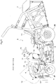
Fig. 1 is a view relating to a first embodiment (same is true with the views up toFig.8 ), which is a left side view showing a riding grass cutting machine, -
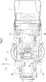
Fig. 2 is a plan view showing the riding grass cutting machine, -
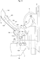
Fig. 3 is a rear view showing a lock mechanism and a detection mechanism, -
Fig. 4 is a view showing a control arrangement, -
Fig. 5 is a rear view showing the lock mechanism and the detection mechanism, which is a rear view showing a state prior to closing of a hood, -
Fig. 6 is a rear view showing the lock mechanism and the detection mechanism, which is a rear view showing a state when the hood is closed, -
Fig. 7 is a rear view showing the lock mechanism and the detection mechanism, which is a rear view showing a state when the hood is pivoted from the closed state to the opening side, -
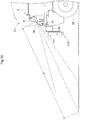
Fig. 8 is a left side view showing an oil line arrangement for a power steering device, -
Fig. 9 is a view relating to a second embodiment (same is true to drawings up toFig. 15 ), which is a left side view showing a riding grass cutting machine, -
Fig. 10 is a plan view showing the riding grass cutting machine, -
Fig. 11 is an exploded front view showing an arrangement of a front portion of a hood, -
Fig. 12 is a front view showing the arrangement of the front portion of the hood, -
Fig. 13 is a left side view in section showing the arrangement of the front portion of the hood, -
Fig. 14 is a left side view in section showing the arrangement of the front portion of the hood when the hood is pivoted to the opening side, and -
Fig. 15 is a left side view showing an exhaust arrangement of a muffler. - Next, a first embodiment will be explained.
- Embodiments for embodying the present invention will be explained with reference to the accompanying drawings. In the following explanation, the direction of arrow F will be defined as "machine body front side", the direction of arrow B will be defined as "machine body rear side", the direction of arrow L will be defined as "machine body left side" and the direction of arrow R will be defined as "machine body right side", respectively.
-
Fig. 1 andFig. 2 show a riding grass cutting machine (corresponding to a "work vehicle" relating to the present invention). This riding grass cutting machine includes a travelingmachine body 1. The travelingmachine body 1 includes amachine body frame 2, a pair of left and rightsteerable front wheels 3F and a pair of left and right drivablerear wheels 3B. Themachine body frame 2 includes a pair of left and rightmain frames 2A extending along the machine body front/rear direction. At a front portion of the travelingmachine body 1, anengine section 4 is provided. Rearwardly of thisengine section 4, adriving section 5 is provided. Under the travelingmachine body 1 and between thefront wheels 3F and therear wheels 3B, a mower 6 (corresponding to an "implement" relating to the present invention) is provided. To a rear portion of the travelingmachine body 1, there is supported agrass collecting container 7 for collecting cut grass pieces from themower 6. - The
engine section 4 includes an engine E, amuffler 8 for exhausting exhaust gas of the engine E, aradiator 9 for discharging heat of engine cooling water, and ahood 10 housing the engine E, etc. The engine E is mounted to a front portion of themachine body frame 2. At the outer circumferential portion of theradiator 9, there is provided a plate-like frame 11 for closing a gap formed around theradiator 9. Thehood 10 is configured to be pivotally opened/closed about a front pivot S1. Adamper 12 is provided for urgingly pivoting thehood 10 toward its opening side. - The
driving section 5 includes a driver'sseat 13 and amaneuvering tower 14. The maneuveringtower 14 includes asteering wheel 15, ameter panel 16, a key switch 17 (corresponding to a "start commanding section" relating to the present invention) for commanding starting of the engine E, and apanel 18 for covering a column (not shown), etc. which supports thesteering wheel 15. - As shown in
Fig. 3 , there is provided alock mechanism 19 for position-maintaining thehood 10 under its closed state. Thislock mechanism 19 is provided at a portion corresponding to a rear portion of thehood 10. Thelock mechanism 19 includes a shaft 20 (corresponding to an "engaged portion" relating to the present invention), ahook 21, and aspring 22. - The
shaft 20 is provided at a rear portion of thehood 10. Theshaft 20, inside thehood 10, is supported to a ceiling plate of thehood 10 via astay 23. Theshaft 20 includes anaction portion 20a extending toward the rear side when thehood 10 is closed. At an upper portion of theframe 11, there is formed anopening 11a which is opened toward the upper side so as to allow entrance of theaction portion 20a therein in association with a pivotal movement of thehood 10 to the closing side. - The
hook 21 is arranged to be pivotable about a pivot axis Y1 (a pivot axis parallel with a pivot axis Y2 which will be described later) between a locked position (seeFig. 3 ) in which thehook 21 is engaged with theaction portion 20a and a released position (seeFig. 7 ) in which thehook 21 is not engaged with theaction portion 20a. The pivot axis Y1 is a pivot axis that extending along the horizontal direction in the machine body front/rear direction. Thehook 21 is disposed rearwardly of theframe 11. Thehook 21 is provided with an actedportion 21a which is subjected to a pressing action by theaction portion 20a from the upper side in association with a pivotal movement of thehood 10 toward the closing side. In thehook 21, there is formed anengagement groove 21b engageable with theaction portion 20a. - A
support plate 24 is provided for supporting thehook 21, etc. Thissupport plate 21 is disposed rearwardly of thehook 21. Thehook 21 is supported to asupport shaft 25 to be pivotable about the pivot axis Y1 and also is supported to thesupport plate 24 via thesupport shaft 25. Thesupport plate 24 is supported to theframe 11 via left and right stays 26. - The
spring 22 urges thehook 21 for its pivotal movement about the pivot axis Y1 toward the locked position side. Thisspring 22 is provided between thehook 21 and thesupport plate 24. Thesupport plate 24 has ahook portion 24a to which thespring 22 is hooked. - At a front face portion of the
support plate 24, there is provided apositioning portion 24b for fixing thehook 21 in position at the locked position. The left stay 26 functions also as a positioning member for positioning thehook 21 at the released position (seeFig. 7 ). To thehook 21, there is connected arelease lever 27 for pivotally operating thehook 21 about the pivot axis Y1 toward the released position in order to release the engagement of thehook 21 with theaction portion 20a. An end portion of therelease lever 27 opposite to thehook 21, ahandgrip 27a is provided. Thishandgrip 27a protrudes upwards from the upper portion of thepanel 18. - As shown in
Fig. 3 , adetection mechanism 28 is provided for detecting an opened or closed state of thehood 10. Thisdetection mechanism 28 is provided at a portion corresponding to the rear portion of thehood 10. Thedetection mechanism 28 includes a shaft 20 (corresponding to a "detected portion" relating to the present invention), a pivot arm 29 (corresponding to a "pivotal member" relating to the present invention), a spring 30 (corresponding to an "urging member" relating to the present invention), and adetection switch 31. Namely, the "detected portion" relating to the present invention and the "engaged portion" relating to the present invention are same (same shaft 20). - The
pivot arm 29 is configured to be pivotable about the pivot axis Y2. This pivot axis Y2 is a pivot axis that extends along the horizontal direction in the machine body front/rear direction. Thepivot arm 29 is disposed between thehook 21 and thesupport plate 24. Namely, thedetection mechanism 28 is disposed at a portion adjacent thelock mechanism 19. Thepivot arm 29 is supported to asupport shaft 32 to be pivotable about the pivot axis Y2 and also supported to thesupport plate 24 via thesupport shaft 32. Thepivot arm 29 includes an actedportion 29a subjected to a pressing action of theaction portion 20a from the above, in association with a pivotal movement of thehood 10 toward the closing side. - At a portion of the
pivot arm 29 opposite to the actedportion 29a relative to the pivot axis Y2, there is provided apin 33 extending along the front/rear direction. Thesupport plate 24 defines aslot 24c through which thepin 33 is inserted. Theslot 24c has an arcuate portion centering about the pivot axis Y2. - Namely, the
pivot arm 29 is arranged to be pivotable about the pivot axis Y2 within an angular range in which thepin 33 is movable within theslot 24c. Here, regarding pivotal positions of thepivot arm 29, a position thereof when thepin 33 has reached the lower end of theslot 24c (the state of thepin 33 coming into contact with a portion along the lower end portion of theslot 24c of the support plate 24) will be referred to as a position corresponding to the state of theaction portion 20a not acting on the pivot arm 29 (the actedportion 29a) (this position will be referred to as "initial positon" hereinafter, seeFig. 7 ), whereas a position thereof when thepin 33 has reached the upper end portion of theslot 24c (the state of thepin 33 coming into contact with a portion along the upper end portion of theslot 24c of the support plate 24) will be referred to as a position corresponding to the closed state of the hood 10 (this position will be referred to as a "closing position" hereinafter, seeFig. 3 ). - The
spring 30 urges thepivot arm 29 for its pivoting about the pivot axis Y2, opposite to the closed position (namely, toward the initial position). Thisspring 30 is disposed rearwardly of thesupport plate 24. Thespring 30 is provided between thepin 33 and thesupport plate 24. Thesupport plate 24 is provided with ahook portion 24d to which thespring 30 is to be hooked. - The
detection switch 31 detects thepivot arm 29 being located at the closing position. Thedetection switch 31 is disposed between theframe 11 and thesupport plate 24. Thedetection switch 31 is supported to thesupport plate 24 as thedetection switch 31 is located adjacent the end portion (right end portion) opposite the actedportion 29a of thepivot arm 29. Thedetection switch 31 includes alever 31a. -
Fig. 4 shows a control arrangement. This control arrangement includes acontrol section 34, the engine E, thekey switch 17 and thedetection switch 31. Thecontrol section 34 is configured to be capable of receiving a signal from thekey switch 17, a signal from thedetection switch 31, and other signals. Thecontrol section 34 starts the engine E in response to a command from thekey switch 17, if thedetection mechanism 28 detects thehood 10 being under the closed state. On the other hand, in case thedetection mechanism 28 does not detect thehood 10 being under the closed state, thecontrol section 24 does not start the engine E against the command from thekey switch 17. - As shown in
Fig. 5 , when thehood 10 is pivoted to the closing side, theaction portion 20a enters theopening 11a to apply a pressing action from above to the actedportion 21a of thehook 21. With this, thehook 21 is pivoted about the pivot axis Y1 toward the releasing position side against the urging force of thespring 22. - Subsequently, the
action portion 20a applies a pressing action from above onto the actedportion 29a of thepivot arm 29. With this, thepivot arm 29 is pivoted about the pivot axis Y2 to the closing position against the urging force of thespring 30. - And, when the
action portion 20a is lowered to the height position corresponding to theengagement groove 21b of thehook 21, under the urging force of thespring 22, thehook 21 is pivoted toward the locked position side about the pivot axis Y1. - Finally, as shown in
Fig. 6 , thehook 21 will come into engagement with theaction portion 20a via theengagement groove 21b and will be fixed position at the locked position by thepositioning portion 24b. Namely, thehood 10 will be maintained under the closed state by thelock mechanism 19. - And, under the above-descried state in which the
hood 10 is position-maintained under the closed state by thelock mechanism 19, thedetection switch 31 is to detect that thepivot arm 29 is located at the closing position as thispivot arm 29 applies a pressing action onto thelever 31a of thedetection switch 31. Namely, the closed state of thehood 10 is detected by thedetection mechanism 28. - Here, as described above, the
control section 34 starts the engine E in response to a command from thekey switch 17, if thedetection mechanism 28 detects thehood 10 being under the closed state. - Thereafter, as shown in
Fig. 7 , when thehook 21 is pivotally operated by therelease lever 27 about the pivot axis Y1 to the releasing position against the urging force of thespring 22, the engagement of thehook 21 with theaction portion 20a will be released. Namely, the position maintenance of thehood 10 under the closed state by thelock mechanism 19 will be released. - And, under the state of release of the position maintenance of the
hood 10 under the closed state by thelock mechanism 19, if thehood 10 is pivoted toward the opening side, theaction portion 20a will be moved upward away from the actedportion 29a of thepivot arm 29. With this, thepivot arm 29 will be pivoted about the pivot axis Y2 to the initial position under the urging force of thespring 30, and thepivot arm 29 will be moved away from thelever 31a of thedetection switch 31. Namely, thedetection mechanism 28 will no longer detect thepivot arm 29 being located at the closing position. - Here, as described above, the
control section 34 does not start the engine E against the command from thekey switch 17, if thedetection mechanism 28 does not detect thehood 10 being under the closed state. - As shown in
Fig. 8 , between thepower steering device 35 for thesteering wheel 15 and a hydraulic device (not shown), there are provided a plurality of pipe-like members. The plurality of pipe-like members include a first pipe-like member 36, a second pipe-like member 37, and a third pipe-like member 38. The first pipe-like member 36 includes a firsthydraulic hose 36a made of soft material (e.g. made of rubber), and a firsthydraulic pipe 36b made of hard material (e.g. made of metal). The firsthydraulic hose 36a and the firsthydraulic pipe 36b are connected to each other via a first joint 36c. The second pipe-like member 37 includes a secondhydraulic hose 37a made of soft material (e.g. made of rubber), and a secondhydraulic pipe 37b made of hard material (e.g. made of metal). The secondhydraulic hose 37a and the secondhydraulic pipe 37b are connected to each other via a second joint 37c. The third pipe-like member 38 includes a third hydraulic hose 38a made of soft material (e.g. made of rubber), and a thirdhydraulic pipe 38b made of hard material (e.g. made of metal). The third hydraulic hose 38a and the thirdhydraulic pipe 38b are connected to each other via a third joint 38c. - The first joint 36c, the second joint 37c and the third joint 38c are disposed inside the
panel 18. The first joint 36c, the second joint 37c and the third joint 38c are disposed with respective vertical positions thereof relative to each other being offset from each other. With this arrangement, when the first joint 36c, the second joint 37c and the third joint 38c are to be fastened or loosened in the limited space available inside thepanel 18 for instance, the adjacent ones of the first joint 36c, the second joint 37c and the third joint 38c will not interfere with each other, and a space for inserting a tool can be secured. -
- (1) In the foregoing embodiment, the
hood 10 is configured to be pivotally opened/closed about the front pivot S1. However, thehood 10 may be configured to be pivotably opened/closed about a rear pivot. - (2) In the foregoing embodiment, the
detection mechanism 28 is provided at a portion corresponding to the rear portion of thehood 10. However, thedetection mechanism 28 may be provided at a portion corresponding to a front portion of thehood 10. In particular, in the case of the arrangement of the above-described embodiment (1) in which thehood 10 is configured to be pivotally opened/closed about the rear pivot, it will be advantageous if thedetection mechanism 28 is provided at a portion corresponding to the front portion of thehood 10. - (3) In the foregoing embodiment, the
detection mechanism 28 includes theshaft 20, thepivot arm 29, thespring 30 and thedetection switch 31. However, thedetection mechanism 28 is not limited to the arrangement relating to the foregoing embodiment. - (4) In the foregoing embodiment, the
lock mechanism 19 includes theshaft 20, thehook 21 and thespring 22. However, thelock mechanism 19 is not limited to the arrangement relating to the foregoing embodiment. - (5) In the foregoing embodiment, the
detection mechanism 28 is disposed at a portion adjacent thelock mechanism 19. However, thedetection mechanism 28 may be disposed at a portion other than the portion adjacent thelock mechanism 19. - (6) In the foregoing embodiment, the "detected portion" and the "engaged portion" relating to the present invention are identical to (same) each other (the shaft 20). However, the "detected portion" and the "engaged portion" relating to the present invention may not be identical to each other.
- (7) The present invention is applicable not only to the riding grass cutting machine, but also to a tractor having an implement mounted at a rear portion of the machine body.
- (8) Incidentally, the present invention is not limited to the foregoing embodiment or the other embodiments described above, but various modifications thereof are possible.
- Next, a second embodiment will be explained.
- As shown in
Fig. 9 andFig 10 , at a front end portion of a travelingmachine body 1, aweight unit 119 is provided. Thisweight unit 119 includes abracket 120 provided at a front end portion of amachine body frame 2 and left and rightfront weights 121 detachably attached to thebracket 120. - A PTO (power take-off)
shaft 122 is provided for taking off power of an engine E for driving amower 6. Between an output shaft (not shown) of the engine E and thePTO shaft 122, there is provided abelt transmission mechanism 123 for transmitting power of the output shaft to thePTO shaft 122. As the power of the output shaft is transmitted by thebelt transmission mechanism 123 to thePTO shaft 122, themower 6 is driven. - At the forward vicinity of the engine E, there is provided a
clutch device 124 for engaging/disengaging power transmission to themower 6. Theclutch device 124, as being positioned forwardly of thebelt transmission mechanism 123, is connected to a font end portion of the output shaft. Theclutch device 124 is constituted of an electromagnetic clutch. Theclutch device 124 is configured to be switchable between a state (engaged state) for transmitting the power of the output shaft to thebelt transmission mechanism 123 and a state (disengaged state) for not transmitting the power of the output shaft to thebelt transmission mechanism 123. - As shown in
Figs. 11 through 13 , thehood 10 includes ahood body portion 125 and afront grill 126. Thefront grill 126 is attached to a front portion of thehood body portion 125. In thefront grill 126, there are formed many ventilation holes (not shown). At a left lower portion of thefront grill 126, there is formed ahole 126a for exposing anexhaust pipe 8a for themuffler 8 to the outside. - Between an upper portion and a lower portion of the front portion of the
hood body portion 125, asupport member 127 is provided. To thissupport member 127, thefront grill 126, etc. are supported. At the front end portions of the left and rightmain frames 2A, there are provided left and right stays 128 respectively. Thehood 10 is supported via thesupport member 127 to the left and right stays 128 to be pivotable about a pivot axis X1. This pivot axis X1 is a pivot axis extending along the machine body left/right direction. - The
support member 127 includes upper and lower horizontal stays 129 extending along the machine body left/right direction, an uppervertical stay 130 connected to the upperhorizontal stay 129 and extending upwards and left and right lowervertical stays 131 connected to the left and right end portions of the upper and lower horizontal stays 129 and extending downwards. The left and right lowervertical stays 131 are supported to the left and right stays 128 via left andright bolts 132 to be pivotable about the pivot axis X1. At the lower end portions of the lowervertical stays 131,support portions 131a are formed. Thesupport portions 131a are placed in abutment against thestays 128 from the lateral outer side and fixed under this state with thebolts 132. Thebolts 132 are inserted into thesupport portions 131a from the lateral outer side. - At a front lower portion of the
hood 10, there is formed anopening 10a which is opened to the lower side. Theopening 10a is formed between thehood body portion 125 and thefront grill 126. Theopening 10a is overlapped with theclutch device 124 as seen in a front view. Theopening 10a is formed to extend with a width greater than the lateral width of theclutch device 124 and to extend to a position higher than the upper end of theclutch device 124. Thesupport portions 131a extend through theopening 10a to the outside of thehood 10. - A
cover member 133 is provided to cover theopening 10a as being disengaged from thehood 10. Thecover member 133 is supported to the left and right stays 128. The left end portion of thecover member 133 is placed in abutment against theleft stay 128 from the front side and fixed under this state with ascrew 134. The right end portion of thecover member 133 is placed in abutment against theright stay 128 from the front side and fixed under this state with ascrew 134. Thescrews 134 are inserted to thecover member 133 from the front side thereof. - At a portion of the
hood 10 along theopening 10a, aframe member 135 is attached. Theframe member 135 has an approximately portal shape as seen in a front view. A gap formed between the portion of thehood 10 along theopening 10a and thecover member 133 is closed by theframe member 135. Theframe member 135 is fixed to the lower horizontal stays 129 withbolts 136. - As shown in
Fig. 14 , when thehood 10 is pivotally opened/closed, thecover member 133 is not pivoted together with thehood 10, but will remain on the side of themachine body frame 2. And, when thehood 10 is pivotally opened/closed, theclutch device 124 enters theopening 10a, so that the front lower portion of thehood 10 does not interfere with theclutch device 124. - As shown in
Fig. 15 , theexhaust pipe 8a extends obliquely from the left side portion of themuffler 8 toward the front lower side. Theexhaust pipe 8a is caused to extend as long as possible so as to prevent exhaust gas from reaching thefront grill 126. With this arrangement, it is possible to prevent the exhaust gas from falling on thefront grill 126, thus soiling or damaging thisfront grill 126. - In order to prevent the exhaust gas from falling on the
front weights 121 and/or thebracket 120, the inclination of theexhaust pipe 8a is set so as to maximize a distance D from the exhaust opening end of theexhaust pipe 8a to the ground surface. With this arrangement, it is possible to prevent the exhaust gas from falling on thefront weights 121 and/or thebracket 120, thus soiling or damaging the same. Further, with the increase of the distance D from the exhaust opening end of theexhaust pipe 8a to the ground surface, the temperature of the exhaust gas in the vicinity of the ground surface is lowered, whereby heat influence to e.g. lawn on the ground surface can be reduced. -
- (1) In the foregoing embodiment, forwardly adjacent the engine E, the
clutch device 124 is provided. However, forwardly adjacent the engine E, theclutch device 124 may not be provided. In this case, forwardly adjacent the engine E, a device other than theclutch device 124 may be provided. - (2) In the foregoing embodiment, at the portion of the
hood 10 along theopening 10a, theframe member 135 is attached. However, at the portion of thehood 10 along theopening 10a, theframe member 135 may not be attached. - (3) In the foregoing embodiment, the
cover member 133 is supported to thestays 128. However, thecover member 133 may be supported to a member other than thestays 128. - (4) The present invention is applicable not only to the riding grass cutting machine, but also to a tractor having an implement mounted at a rear portion of the machine body.
- (5) Incidentally, the present invention is not limited to the foregoing embodiment or the other embodiments described above, but various modifications thereof are possible.
-
- 2:
- machine body frame
- 6:
- mower (implement)
- 10:
- hood
- 10a:
- opening
- 17:
- key switch (start commanding section)
- 19:
- lock mechanism
- 20:
- shaft (detected portion, engaged portion)
- 21:
- hook
- 28:
- detection mechanism
- 29:
- pivot arm (pivotal member)
- 30:
- spring (urging member)
- 31:
- detection switch
- 34:
- control section
- 124:
- clutch device
- 126:
- front grill
- 128:
- stay
- 133:
- cover member
- 135:
- frame member
- E:
- engine
- S1:
- front pivot
- Y1:
- pivot axis
- Y2:
- pivot axis
Claims (12)
- A work vehicle comprising:an engine (E);an openable/closable hood (10) housing the engine (E);a detection mechanism (28) for detecting an opened/closed state of the hood (10);a start commanding section (17) for commanding start of the engine (E); anda control section (34) for controlling the engine (E);wherein the control section (34) is configure to do not start the engine (E) against a command if any from the start commanding section (17), if a closed state of the hood (10) is not detected by the detection mechanism (28).
- The work vehicle of claim 1, wherein:the hood (10) is configured to be pivotally openable/closable about a front pivot (S1); andthe detection mechanism (28) is provided at a portion corresponding to a rear portion of the hood (10).
- The work vehicle of claim 2, wherein the detection mechanism (28) includes:a detected portion (20) provided at a rear portion of the hood (10);a pivotal member (29) pivotable about a pivot axis (Y2) extending along the horizontal direction and subjected to a pressing action from above by the detected portion (20) in association with a pivotal movement of the hood (10) toward the closing side; anda detection switch (31) configured to detect the pivotal member (29) being located at a closing position corresponding to the closed state of the hood (10).
- The work vehicle of claim 3, wherein the detection mechanism (28) includes an urging member (30) configured to urgingly pivot the pivotal member (29) about the pivot axis (Y2) to the side opposite to the closing position.
- The work vehicle of claim 3 or 4, wherein:there is provided a lock mechanism (19) for position-maintaining the hood (10) under the closed state; andthe detection mechanism (28) is disposed at a portion adjacent to the lock mechanism (19).
- The work vehicle of claim 5, wherein:
the lock mechanism (19) includes:an engaged portion (20) provided at a rear portion of the hood (10);a hook (21) configured to be pivotable about a pivot axis (Y1) extending parallel with the pivot axis (Y2) and subjected to a pressing action from above by the engaged portion (20) in association with a pivotal movement of the hood (10) toward the closing side to be engaged with the engaged portion (20); andthe detected portion (20) and the engaged portion (20) are identical to each other. - A work vehicle comprising:an engine (E) mounted at a front portion of a machine body frame (2); anda hood (10) pivotally openable/closable about a front pivot (S1) and housing the engine (E);wherein at a front lower portion of the hood (10), there is formed an opening (10a) opened toward the lower side; andthere is provided a cover member (133) supported to the machine body frame (2), the cover member (133) being configured to cover the opening (10a) when disengaged from the hood (10).
- The work vehicle of claim 7, wherein:forwardly adjacent the engine (E), there is provided a clutch device (124) for engaging/disengaging power transmission to an implement (6); andthe opening (10a) is overlapped with the clutch device (124) as seen in a front view.
- The work vehicle of claim 8, wherein the opening (10a) has a shape having a wider lateral width than the clutch device (124) and extending to an upper side height position higher than the upper end of the clutch device (124).
- The work vehicle of any one of claims 7-9, wherein at a portion of the hood (10) along the opening (10a), a frame member (135) is attached.
- The work vehicle of any one of claims 7-10, wherein:the machine body frame (2) includes a stay (128) that pivotally supports the hood (10); andthe cover member (133) is supported to the stay (128).
- The work vehicle of any one of claims 7-11, wherein:at a front portion of the hood (10), a front grill (126) is provided; andthe opening (10a) is formed at a front lower portion of the front grill (126).
Priority Applications (2)
| Application Number | Priority Date | Filing Date | Title |
|---|---|---|---|
| EP21162423.4A EP3854195B1 (en) | 2019-03-13 | 2019-12-02 | Work vehicle |
| EP22184415.2A EP4091419A1 (en) | 2019-03-13 | 2019-12-02 | Work vehicle |
Applications Claiming Priority (2)
| Application Number | Priority Date | Filing Date | Title |
|---|---|---|---|
| JP2019046290A JP7193386B2 (en) | 2019-03-13 | 2019-03-13 | work vehicle |
| JP2019096111A JP7162566B2 (en) | 2019-05-22 | 2019-05-22 | work vehicle |
Related Child Applications (4)
| Application Number | Title | Priority Date | Filing Date |
|---|---|---|---|
| EP21162423.4A Division EP3854195B1 (en) | 2019-03-13 | 2019-12-02 | Work vehicle |
| EP21162423.4A Division-Into EP3854195B1 (en) | 2019-03-13 | 2019-12-02 | Work vehicle |
| EP22184415.2A Division-Into EP4091419A1 (en) | 2019-03-13 | 2019-12-02 | Work vehicle |
| EP22184415.2A Division EP4091419A1 (en) | 2019-03-13 | 2019-12-02 | Work vehicle |
Publications (2)
| Publication Number | Publication Date |
|---|---|
| EP3707985A1 true EP3707985A1 (en) | 2020-09-16 |
| EP3707985B1 EP3707985B1 (en) | 2022-08-24 |
Family
ID=68762655
Family Applications (3)
| Application Number | Title | Priority Date | Filing Date |
|---|---|---|---|
| EP22184415.2A Pending EP4091419A1 (en) | 2019-03-13 | 2019-12-02 | Work vehicle |
| EP21162423.4A Active EP3854195B1 (en) | 2019-03-13 | 2019-12-02 | Work vehicle |
| EP19212949.2A Active EP3707985B1 (en) | 2019-03-13 | 2019-12-02 | Work vehicle |
Family Applications Before (2)
| Application Number | Title | Priority Date | Filing Date |
|---|---|---|---|
| EP22184415.2A Pending EP4091419A1 (en) | 2019-03-13 | 2019-12-02 | Work vehicle |
| EP21162423.4A Active EP3854195B1 (en) | 2019-03-13 | 2019-12-02 | Work vehicle |
Country Status (1)
| Country | Link |
|---|---|
| EP (3) | EP4091419A1 (en) |
Citations (7)
| Publication number | Priority date | Publication date | Assignee | Title |
|---|---|---|---|---|
| JPH08268105A (en) * | 1995-03-30 | 1996-10-15 | Honda Motor Co Ltd | Operation controller for working vehicle |
| US20060225934A1 (en) * | 2005-04-11 | 2006-10-12 | Eric Fobean | Child's riding vehicle |
| WO2013062574A1 (en) * | 2011-10-28 | 2013-05-02 | Husqvarna Consumer Outdoor Products N.A., Inc. | Start fault indicator system |
| EP2826658A1 (en) * | 2013-07-18 | 2015-01-21 | Kubota Corporation | Work machine |
| US20170129544A1 (en) * | 2015-11-09 | 2017-05-11 | Kubota Corporation | Work Vehicle |
| JP2018034679A (en) | 2016-08-31 | 2018-03-08 | 株式会社クボタ | Tractor |
| JP2018184168A (en) | 2018-08-21 | 2018-11-22 | 株式会社クボタ | Work vehicle |
Family Cites Families (5)
| Publication number | Priority date | Publication date | Assignee | Title |
|---|---|---|---|---|
| JP2000094984A (en) * | 1998-09-24 | 2000-04-04 | Nissan Motor Co Ltd | Engine starting controller for industrial vehicle |
| US6460644B1 (en) * | 2000-08-24 | 2002-10-08 | Deere & Company | Two position tilt hood |
| JP2009227098A (en) * | 2008-03-24 | 2009-10-08 | Tcm Corp | Working vehicle |
| US10694676B2 (en) * | 2017-02-23 | 2020-06-30 | Kubota Corporation | Riding-type mower |
| EP3375669B1 (en) * | 2017-03-15 | 2019-11-06 | Kubota Corporation | Work vehicle |
-
2019
- 2019-12-02 EP EP22184415.2A patent/EP4091419A1/en active Pending
- 2019-12-02 EP EP21162423.4A patent/EP3854195B1/en active Active
- 2019-12-02 EP EP19212949.2A patent/EP3707985B1/en active Active
Patent Citations (7)
| Publication number | Priority date | Publication date | Assignee | Title |
|---|---|---|---|---|
| JPH08268105A (en) * | 1995-03-30 | 1996-10-15 | Honda Motor Co Ltd | Operation controller for working vehicle |
| US20060225934A1 (en) * | 2005-04-11 | 2006-10-12 | Eric Fobean | Child's riding vehicle |
| WO2013062574A1 (en) * | 2011-10-28 | 2013-05-02 | Husqvarna Consumer Outdoor Products N.A., Inc. | Start fault indicator system |
| EP2826658A1 (en) * | 2013-07-18 | 2015-01-21 | Kubota Corporation | Work machine |
| US20170129544A1 (en) * | 2015-11-09 | 2017-05-11 | Kubota Corporation | Work Vehicle |
| JP2018034679A (en) | 2016-08-31 | 2018-03-08 | 株式会社クボタ | Tractor |
| JP2018184168A (en) | 2018-08-21 | 2018-11-22 | 株式会社クボタ | Work vehicle |
Also Published As
| Publication number | Publication date |
|---|---|
| EP3854195B1 (en) | 2023-12-13 |
| EP3707985B1 (en) | 2022-08-24 |
| EP3854195A1 (en) | 2021-07-28 |
| EP4091419A1 (en) | 2022-11-23 |
Similar Documents
| Publication | Publication Date | Title |
|---|---|---|
| CA2541101C (en) | Tractor | |
| WO2016189940A1 (en) | Tractor | |
| EP2826658B1 (en) | Work machine | |
| US10036303B2 (en) | Lawn mower | |
| EP3854195B1 (en) | Work vehicle | |
| JP2693336B2 (en) | Mounting device for tractor and work implement | |
| JP4917854B2 (en) | Work vehicle | |
| JP4359574B2 (en) | Walking work vehicle | |
| JP2010265674A (en) | Working machine | |
| WO2017170642A1 (en) | Working machine | |
| JP7162566B2 (en) | work vehicle | |
| JP7193386B2 (en) | work vehicle | |
| JP2007302139A (en) | Mobile agricultural machine | |
| JP4838159B2 (en) | Walking type work machine | |
| JP2008082128A (en) | Loader working machine | |
| JP2009001139A (en) | Riding type work vehicle | |
| JP2006158285A (en) | Apparatus for mounting implement | |
| JP2021046098A (en) | Agricultural machine | |
| JP2021045083A (en) | Agricultural machine | |
| JP2021045084A (en) | Agricultural machine | |
| JP2021045082A (en) | Agricultural machine | |
| JP3469085B2 (en) | Engine room structure of running vehicle | |
| JP4347600B2 (en) | Small mobile agricultural machine | |
| JP2019116234A (en) | Work vehicle | |
| JP5901562B2 (en) | Work vehicle |
Legal Events
| Date | Code | Title | Description |
|---|---|---|---|
| PUAI | Public reference made under article 153(3) epc to a published international application that has entered the european phase |
Free format text: ORIGINAL CODE: 0009012 |
|
| STAA | Information on the status of an ep patent application or granted ep patent |
Free format text: STATUS: REQUEST FOR EXAMINATION WAS MADE |
|
| 17P | Request for examination filed |
Effective date: 20191202 |
|
| AK | Designated contracting states |
Kind code of ref document: A1 Designated state(s): AL AT BE BG CH CY CZ DE DK EE ES FI FR GB GR HR HU IE IS IT LI LT LU LV MC MK MT NL NO PL PT RO RS SE SI SK SM TR |
|
| AX | Request for extension of the european patent |
Extension state: BA ME |
|
| STAA | Information on the status of an ep patent application or granted ep patent |
Free format text: STATUS: EXAMINATION IS IN PROGRESS |
|
| 17Q | First examination report despatched |
Effective date: 20210331 |
|
| GRAP | Despatch of communication of intention to grant a patent |
Free format text: ORIGINAL CODE: EPIDOSNIGR1 |
|
| STAA | Information on the status of an ep patent application or granted ep patent |
Free format text: STATUS: GRANT OF PATENT IS INTENDED |
|
| INTG | Intention to grant announced |
Effective date: 20211018 |
|
| GRAJ | Information related to disapproval of communication of intention to grant by the applicant or resumption of examination proceedings by the epo deleted |
Free format text: ORIGINAL CODE: EPIDOSDIGR1 |
|
| STAA | Information on the status of an ep patent application or granted ep patent |
Free format text: STATUS: EXAMINATION IS IN PROGRESS |
|
| GRAP | Despatch of communication of intention to grant a patent |
Free format text: ORIGINAL CODE: EPIDOSNIGR1 |
|
| STAA | Information on the status of an ep patent application or granted ep patent |
Free format text: STATUS: GRANT OF PATENT IS INTENDED |
|
| INTC | Intention to grant announced (deleted) | ||
| INTG | Intention to grant announced |
Effective date: 20220303 |
|
| GRAS | Grant fee paid |
Free format text: ORIGINAL CODE: EPIDOSNIGR3 |
|
| GRAA | (expected) grant |
Free format text: ORIGINAL CODE: 0009210 |
|
| STAA | Information on the status of an ep patent application or granted ep patent |
Free format text: STATUS: THE PATENT HAS BEEN GRANTED |
|
| AK | Designated contracting states |
Kind code of ref document: B1 Designated state(s): AL AT BE BG CH CY CZ DE DK EE ES FI FR GB GR HR HU IE IS IT LI LT LU LV MC MK MT NL NO PL PT RO RS SE SI SK SM TR |
|
| REG | Reference to a national code |
Ref country code: CH Ref legal event code: EP |
|
| REG | Reference to a national code |
Ref country code: IE Ref legal event code: FG4D |
|
| REG | Reference to a national code |
Ref country code: AT Ref legal event code: REF Ref document number: 1513023 Country of ref document: AT Kind code of ref document: T Effective date: 20220915 Ref country code: DE Ref legal event code: R096 Ref document number: 602019018615 Country of ref document: DE |
|
| REG | Reference to a national code |
Ref country code: LT Ref legal event code: MG9D |
|
| REG | Reference to a national code |
Ref country code: NL Ref legal event code: MP Effective date: 20220824 |
|
| PG25 | Lapsed in a contracting state [announced via postgrant information from national office to epo] |
Ref country code: SE Free format text: LAPSE BECAUSE OF FAILURE TO SUBMIT A TRANSLATION OF THE DESCRIPTION OR TO PAY THE FEE WITHIN THE PRESCRIBED TIME-LIMIT Effective date: 20220824 Ref country code: RS Free format text: LAPSE BECAUSE OF FAILURE TO SUBMIT A TRANSLATION OF THE DESCRIPTION OR TO PAY THE FEE WITHIN THE PRESCRIBED TIME-LIMIT Effective date: 20220824 Ref country code: PT Free format text: LAPSE BECAUSE OF FAILURE TO SUBMIT A TRANSLATION OF THE DESCRIPTION OR TO PAY THE FEE WITHIN THE PRESCRIBED TIME-LIMIT Effective date: 20221226 Ref country code: NO Free format text: LAPSE BECAUSE OF FAILURE TO SUBMIT A TRANSLATION OF THE DESCRIPTION OR TO PAY THE FEE WITHIN THE PRESCRIBED TIME-LIMIT Effective date: 20221124 Ref country code: NL Free format text: LAPSE BECAUSE OF FAILURE TO SUBMIT A TRANSLATION OF THE DESCRIPTION OR TO PAY THE FEE WITHIN THE PRESCRIBED TIME-LIMIT Effective date: 20220824 Ref country code: LV Free format text: LAPSE BECAUSE OF FAILURE TO SUBMIT A TRANSLATION OF THE DESCRIPTION OR TO PAY THE FEE WITHIN THE PRESCRIBED TIME-LIMIT Effective date: 20220824 Ref country code: LT Free format text: LAPSE BECAUSE OF FAILURE TO SUBMIT A TRANSLATION OF THE DESCRIPTION OR TO PAY THE FEE WITHIN THE PRESCRIBED TIME-LIMIT Effective date: 20220824 Ref country code: FI Free format text: LAPSE BECAUSE OF FAILURE TO SUBMIT A TRANSLATION OF THE DESCRIPTION OR TO PAY THE FEE WITHIN THE PRESCRIBED TIME-LIMIT Effective date: 20220824 |
|
| REG | Reference to a national code |
Ref country code: AT Ref legal event code: MK05 Ref document number: 1513023 Country of ref document: AT Kind code of ref document: T Effective date: 20220824 |
|
| PG25 | Lapsed in a contracting state [announced via postgrant information from national office to epo] |
Ref country code: PL Free format text: LAPSE BECAUSE OF FAILURE TO SUBMIT A TRANSLATION OF THE DESCRIPTION OR TO PAY THE FEE WITHIN THE PRESCRIBED TIME-LIMIT Effective date: 20220824 Ref country code: IS Free format text: LAPSE BECAUSE OF FAILURE TO SUBMIT A TRANSLATION OF THE DESCRIPTION OR TO PAY THE FEE WITHIN THE PRESCRIBED TIME-LIMIT Effective date: 20221224 Ref country code: HR Free format text: LAPSE BECAUSE OF FAILURE TO SUBMIT A TRANSLATION OF THE DESCRIPTION OR TO PAY THE FEE WITHIN THE PRESCRIBED TIME-LIMIT Effective date: 20220824 Ref country code: GR Free format text: LAPSE BECAUSE OF FAILURE TO SUBMIT A TRANSLATION OF THE DESCRIPTION OR TO PAY THE FEE WITHIN THE PRESCRIBED TIME-LIMIT Effective date: 20221125 |
|
| PG25 | Lapsed in a contracting state [announced via postgrant information from national office to epo] |
Ref country code: SM Free format text: LAPSE BECAUSE OF FAILURE TO SUBMIT A TRANSLATION OF THE DESCRIPTION OR TO PAY THE FEE WITHIN THE PRESCRIBED TIME-LIMIT Effective date: 20220824 Ref country code: RO Free format text: LAPSE BECAUSE OF FAILURE TO SUBMIT A TRANSLATION OF THE DESCRIPTION OR TO PAY THE FEE WITHIN THE PRESCRIBED TIME-LIMIT Effective date: 20220824 Ref country code: ES Free format text: LAPSE BECAUSE OF FAILURE TO SUBMIT A TRANSLATION OF THE DESCRIPTION OR TO PAY THE FEE WITHIN THE PRESCRIBED TIME-LIMIT Effective date: 20220824 Ref country code: DK Free format text: LAPSE BECAUSE OF FAILURE TO SUBMIT A TRANSLATION OF THE DESCRIPTION OR TO PAY THE FEE WITHIN THE PRESCRIBED TIME-LIMIT Effective date: 20220824 Ref country code: CZ Free format text: LAPSE BECAUSE OF FAILURE TO SUBMIT A TRANSLATION OF THE DESCRIPTION OR TO PAY THE FEE WITHIN THE PRESCRIBED TIME-LIMIT Effective date: 20220824 Ref country code: AT Free format text: LAPSE BECAUSE OF FAILURE TO SUBMIT A TRANSLATION OF THE DESCRIPTION OR TO PAY THE FEE WITHIN THE PRESCRIBED TIME-LIMIT Effective date: 20220824 |
|
| REG | Reference to a national code |
Ref country code: DE Ref legal event code: R097 Ref document number: 602019018615 Country of ref document: DE |
|
| PG25 | Lapsed in a contracting state [announced via postgrant information from national office to epo] |
Ref country code: SK Free format text: LAPSE BECAUSE OF FAILURE TO SUBMIT A TRANSLATION OF THE DESCRIPTION OR TO PAY THE FEE WITHIN THE PRESCRIBED TIME-LIMIT Effective date: 20220824 Ref country code: EE Free format text: LAPSE BECAUSE OF FAILURE TO SUBMIT A TRANSLATION OF THE DESCRIPTION OR TO PAY THE FEE WITHIN THE PRESCRIBED TIME-LIMIT Effective date: 20220824 |
|
| PG25 | Lapsed in a contracting state [announced via postgrant information from national office to epo] |
Ref country code: AL Free format text: LAPSE BECAUSE OF FAILURE TO SUBMIT A TRANSLATION OF THE DESCRIPTION OR TO PAY THE FEE WITHIN THE PRESCRIBED TIME-LIMIT Effective date: 20220824 |
|
| PLBE | No opposition filed within time limit |
Free format text: ORIGINAL CODE: 0009261 |
|
| STAA | Information on the status of an ep patent application or granted ep patent |
Free format text: STATUS: NO OPPOSITION FILED WITHIN TIME LIMIT |
|
| REG | Reference to a national code |
Ref country code: DE Ref legal event code: R119 Ref document number: 602019018615 Country of ref document: DE |
|
| REG | Reference to a national code |
Ref country code: CH Ref legal event code: PL |
|
| 26N | No opposition filed |
Effective date: 20230525 |
|
| REG | Reference to a national code |
Ref country code: BE Ref legal event code: MM Effective date: 20221231 |
|
| PG25 | Lapsed in a contracting state [announced via postgrant information from national office to epo] |
Ref country code: SI Free format text: LAPSE BECAUSE OF FAILURE TO SUBMIT A TRANSLATION OF THE DESCRIPTION OR TO PAY THE FEE WITHIN THE PRESCRIBED TIME-LIMIT Effective date: 20220824 Ref country code: LU Free format text: LAPSE BECAUSE OF NON-PAYMENT OF DUE FEES Effective date: 20221202 |
|
| PG25 | Lapsed in a contracting state [announced via postgrant information from national office to epo] |
Ref country code: LI Free format text: LAPSE BECAUSE OF NON-PAYMENT OF DUE FEES Effective date: 20221231 Ref country code: IE Free format text: LAPSE BECAUSE OF NON-PAYMENT OF DUE FEES Effective date: 20221202 Ref country code: DE Free format text: LAPSE BECAUSE OF NON-PAYMENT OF DUE FEES Effective date: 20230701 Ref country code: CH Free format text: LAPSE BECAUSE OF NON-PAYMENT OF DUE FEES Effective date: 20221231 |
|
| PG25 | Lapsed in a contracting state [announced via postgrant information from national office to epo] |
Ref country code: BE Free format text: LAPSE BECAUSE OF NON-PAYMENT OF DUE FEES Effective date: 20221231 |
|
| PGFP | Annual fee paid to national office [announced via postgrant information from national office to epo] |
Ref country code: FR Payment date: 20231108 Year of fee payment: 5 |
|
| PG25 | Lapsed in a contracting state [announced via postgrant information from national office to epo] |
Ref country code: CY Free format text: LAPSE BECAUSE OF FAILURE TO SUBMIT A TRANSLATION OF THE DESCRIPTION OR TO PAY THE FEE WITHIN THE PRESCRIBED TIME-LIMIT Effective date: 20220824 |