EP3705875B1 - An apparatus and method for detecting photoluminescent light emitted from a sample - Google Patents
An apparatus and method for detecting photoluminescent light emitted from a sample Download PDFInfo
- Publication number
- EP3705875B1 EP3705875B1 EP19160857.9A EP19160857A EP3705875B1 EP 3705875 B1 EP3705875 B1 EP 3705875B1 EP 19160857 A EP19160857 A EP 19160857A EP 3705875 B1 EP3705875 B1 EP 3705875B1
- Authority
- EP
- European Patent Office
- Prior art keywords
- light
- sample
- wavelength
- interference filter
- photo
- Prior art date
- Legal status (The legal status is an assumption and is not a legal conclusion. Google has not performed a legal analysis and makes no representation as to the accuracy of the status listed.)
- Active
Links
- 238000000034 method Methods 0.000 title claims description 27
- 230000005284 excitation Effects 0.000 claims description 57
- 239000002245 particle Substances 0.000 claims description 41
- 239000000463 material Substances 0.000 claims description 18
- 238000007781 pre-processing Methods 0.000 claims description 18
- 238000001514 detection method Methods 0.000 claims description 6
- 238000005424 photoluminescence Methods 0.000 claims description 3
- 210000001124 body fluid Anatomy 0.000 claims 3
- 239000010839 body fluid Substances 0.000 claims 3
- 230000001939 inductive effect Effects 0.000 claims 1
- 238000005259 measurement Methods 0.000 description 27
- 238000004458 analytical method Methods 0.000 description 24
- 238000012545 processing Methods 0.000 description 19
- 239000000758 substrate Substances 0.000 description 18
- 230000003287 optical effect Effects 0.000 description 17
- 239000000306 component Substances 0.000 description 16
- 239000008364 bulk solution Substances 0.000 description 11
- 238000003384 imaging method Methods 0.000 description 9
- 230000001902 propagating effect Effects 0.000 description 9
- 230000005540 biological transmission Effects 0.000 description 7
- 210000004027 cell Anatomy 0.000 description 7
- 239000000126 substance Substances 0.000 description 7
- 238000004891 communication Methods 0.000 description 6
- 238000005286 illumination Methods 0.000 description 6
- 238000000926 separation method Methods 0.000 description 4
- 238000000204 total internal reflection microscopy Methods 0.000 description 4
- 230000000903 blocking effect Effects 0.000 description 3
- 230000007423 decrease Effects 0.000 description 3
- 238000004519 manufacturing process Methods 0.000 description 3
- 238000002834 transmittance Methods 0.000 description 3
- 241000700605 Viruses Species 0.000 description 2
- 210000000170 cell membrane Anatomy 0.000 description 2
- 230000008859 change Effects 0.000 description 2
- 230000001419 dependent effect Effects 0.000 description 2
- 230000023077 detection of light stimulus Effects 0.000 description 2
- 230000000694 effects Effects 0.000 description 2
- 239000012530 fluid Substances 0.000 description 2
- 239000011521 glass Substances 0.000 description 2
- 238000004020 luminiscence type Methods 0.000 description 2
- 238000002156 mixing Methods 0.000 description 2
- 230000037361 pathway Effects 0.000 description 2
- 239000004033 plastic Substances 0.000 description 2
- 230000008569 process Effects 0.000 description 2
- 238000010223 real-time analysis Methods 0.000 description 2
- 230000004044 response Effects 0.000 description 2
- 230000035945 sensitivity Effects 0.000 description 2
- 239000000243 solution Substances 0.000 description 2
- 230000002123 temporal effect Effects 0.000 description 2
- 239000004793 Polystyrene Substances 0.000 description 1
- 238000003556 assay Methods 0.000 description 1
- 238000012742 biochemical analysis Methods 0.000 description 1
- 239000012620 biological material Substances 0.000 description 1
- 238000000576 coating method Methods 0.000 description 1
- 230000000295 complement effect Effects 0.000 description 1
- 238000004590 computer program Methods 0.000 description 1
- 239000000356 contaminant Substances 0.000 description 1
- 238000011109 contamination Methods 0.000 description 1
- 239000008358 core component Substances 0.000 description 1
- 238000013461 design Methods 0.000 description 1
- 238000000295 emission spectrum Methods 0.000 description 1
- 238000001917 fluorescence detection Methods 0.000 description 1
- 238000002795 fluorescence method Methods 0.000 description 1
- 238000003780 insertion Methods 0.000 description 1
- 230000037431 insertion Effects 0.000 description 1
- 229920002223 polystyrene Polymers 0.000 description 1
- 230000000644 propagated effect Effects 0.000 description 1
- 102000004169 proteins and genes Human genes 0.000 description 1
- 108090000623 proteins and genes Proteins 0.000 description 1
- 238000004445 quantitative analysis Methods 0.000 description 1
- 229920006395 saturated elastomer Polymers 0.000 description 1
- 238000009738 saturating Methods 0.000 description 1
- 239000004065 semiconductor Substances 0.000 description 1
- 239000007787 solid Substances 0.000 description 1
- 238000004381 surface treatment Methods 0.000 description 1
- 238000011144 upstream manufacturing Methods 0.000 description 1
- 239000013598 vector Substances 0.000 description 1
- 239000011345 viscous material Substances 0.000 description 1
Images


Classifications
-
- G—PHYSICS
- G01—MEASURING; TESTING
- G01N—INVESTIGATING OR ANALYSING MATERIALS BY DETERMINING THEIR CHEMICAL OR PHYSICAL PROPERTIES
- G01N21/00—Investigating or analysing materials by the use of optical means, i.e. using sub-millimetre waves, infrared, visible or ultraviolet light
- G01N21/17—Systems in which incident light is modified in accordance with the properties of the material investigated
- G01N21/47—Scattering, i.e. diffuse reflection
- G01N21/49—Scattering, i.e. diffuse reflection within a body or fluid
- G01N21/51—Scattering, i.e. diffuse reflection within a body or fluid inside a container, e.g. in an ampoule
-
- G—PHYSICS
- G01—MEASURING; TESTING
- G01N—INVESTIGATING OR ANALYSING MATERIALS BY DETERMINING THEIR CHEMICAL OR PHYSICAL PROPERTIES
- G01N21/00—Investigating or analysing materials by the use of optical means, i.e. using sub-millimetre waves, infrared, visible or ultraviolet light
- G01N21/17—Systems in which incident light is modified in accordance with the properties of the material investigated
- G01N21/47—Scattering, i.e. diffuse reflection
- G01N21/49—Scattering, i.e. diffuse reflection within a body or fluid
-
- G—PHYSICS
- G01—MEASURING; TESTING
- G01N—INVESTIGATING OR ANALYSING MATERIALS BY DETERMINING THEIR CHEMICAL OR PHYSICAL PROPERTIES
- G01N21/00—Investigating or analysing materials by the use of optical means, i.e. using sub-millimetre waves, infrared, visible or ultraviolet light
- G01N21/62—Systems in which the material investigated is excited whereby it emits light or causes a change in wavelength of the incident light
- G01N21/63—Systems in which the material investigated is excited whereby it emits light or causes a change in wavelength of the incident light optically excited
- G01N21/64—Fluorescence; Phosphorescence
- G01N21/645—Specially adapted constructive features of fluorimeters
- G01N21/6452—Individual samples arranged in a regular 2D-array, e.g. multiwell plates
- G01N21/6454—Individual samples arranged in a regular 2D-array, e.g. multiwell plates using an integrated detector array
-
- G—PHYSICS
- G01—MEASURING; TESTING
- G01N—INVESTIGATING OR ANALYSING MATERIALS BY DETERMINING THEIR CHEMICAL OR PHYSICAL PROPERTIES
- G01N21/00—Investigating or analysing materials by the use of optical means, i.e. using sub-millimetre waves, infrared, visible or ultraviolet light
- G01N21/62—Systems in which the material investigated is excited whereby it emits light or causes a change in wavelength of the incident light
- G01N21/63—Systems in which the material investigated is excited whereby it emits light or causes a change in wavelength of the incident light optically excited
- G01N21/64—Fluorescence; Phosphorescence
- G01N21/645—Specially adapted constructive features of fluorimeters
- G01N21/648—Specially adapted constructive features of fluorimeters using evanescent coupling or surface plasmon coupling for the excitation of fluorescence
-
- G—PHYSICS
- G01—MEASURING; TESTING
- G01N—INVESTIGATING OR ANALYSING MATERIALS BY DETERMINING THEIR CHEMICAL OR PHYSICAL PROPERTIES
- G01N21/00—Investigating or analysing materials by the use of optical means, i.e. using sub-millimetre waves, infrared, visible or ultraviolet light
- G01N21/62—Systems in which the material investigated is excited whereby it emits light or causes a change in wavelength of the incident light
- G01N21/63—Systems in which the material investigated is excited whereby it emits light or causes a change in wavelength of the incident light optically excited
- G01N21/64—Fluorescence; Phosphorescence
- G01N21/645—Specially adapted constructive features of fluorimeters
- G01N2021/6463—Optics
- G01N2021/6465—Angular discrimination
-
- G—PHYSICS
- G01—MEASURING; TESTING
- G01N—INVESTIGATING OR ANALYSING MATERIALS BY DETERMINING THEIR CHEMICAL OR PHYSICAL PROPERTIES
- G01N21/00—Investigating or analysing materials by the use of optical means, i.e. using sub-millimetre waves, infrared, visible or ultraviolet light
- G01N21/62—Systems in which the material investigated is excited whereby it emits light or causes a change in wavelength of the incident light
- G01N21/63—Systems in which the material investigated is excited whereby it emits light or causes a change in wavelength of the incident light optically excited
- G01N21/64—Fluorescence; Phosphorescence
- G01N21/645—Specially adapted constructive features of fluorimeters
- G01N2021/6463—Optics
- G01N2021/6471—Special filters, filter wheel
Definitions
- the present disclosure relates to an apparatus for detecting photoluminescent light emitted from a sample.
- the disclosure relates to detecting supercritical angle fluorescent light.
- the present disclosure relates to a biosensor system making use of detection of supercritical angle photoluminescent light from a sample.
- Fluorescence is commonly used for studying samples in cell and molecular biology.
- the sample may be prepared by providing a fluorescent substance (fluorophore), that may be selectively bound to a part of the sample that is to be analyzed.
- a fluorescent substance fluorophore
- an intrinsic fluorescence of the sample may be used in exciting fluorescent light from the sample.
- target molecules and fluorophores are immobilized on a bottom surface of sample holder.
- a bulk solution may thus comprise a large number of fluorophores that may make it impossible to distinguish fluorescence from the target molecules from the bulk solution fluorescence. Thus, it may be necessary to wait a long time for the fluorophores in the bulk solution to settle to the surface before an analysis may be made.
- An alternative is to selectively analyze surface bound fluorophores. Thus, surface sensitive techniques are of special interest.
- evanescent excitation may be used for exciting only a thin portion of a sample at the surface of the sample holder.
- the evanescent excitation is based on a small portion of light escaping a surface in which total internal reflection occurs and intensity of the light will very quickly decrease with distance from the surface.
- target molecules may be selectively excited in order to avoid fluorescent light of interest to be drowned by fluorescence from the bulk solution.
- fluorophores can be described by an electrical dipole, which preferentially emits light in certain axes depending on orientation of the fluorophore.
- fluorophores also have an evanescent non-propagating component. A part of this non-propagating component becomes propagating when the fluorophore is at or below a distance of one wavelength from a surface interface between two materials, specifically when the other material has a larger refractive index than the material that encloses the fluorophore. This is called supercritical angle fluorescence (SAF) and is emitted above the critical angle of the interface between the two materials.
- SAF supercritical angle fluorescence
- SAF phenomenon has been used together with TIRF in order to further improve resolution in imaging of portions of a sample close to a surface.
- US 2016/0011112 A1 discloses a sample plate and an analyzing method, wherein the sample plate comprises a substrate, at least one sensor site on a first surface of the substrate and at least one optical element on a second surface of the substrate.
- the sample plate is further provided with a waveguide on the second surface for guiding an excitation signal to interact with the at least one sensor site.
- the method comprises bringing the sample in contact with at least one sensor site, exciting the sensor site in order to obtain an emitted signal, and selectively collecting the emitted signal by means of at least one optical element and utilizing a supercritical angle fluorescence method.
- the optical elements which can be formed by diffractive elements or other integrated (e.g.
- Fresnel lens type structures facilitating the collection of light emitted to the desired angles, collect the emitted light with the highest intensity, i.e. at/above the critical angle of total internal reflection.
- the light emitted at smaller angles is blocked by non-transparent/absorbing films/coatings/blockers on/under the bottom of the waveguide and to the other direction by the appropriate blockers and structures, e.g. reflective surfaces or diffractive elements.
- US 2013/0236982 A1 discloses a sensor comprising a substrate having a first surface and a second surface.
- the first surface has at least one sensor site provided thereon.
- the substrate is configured such that on excitation of a sample provided at the sensor site, luminescence originating from the sesnsor site propagates into the substrate, the second surface of the substrate being configured to selectively transmit the luminescence propagating within the substrates at angles greater than the critical angle out of the substrate where it may be detected by a detector provided below the substrate.
- US 2017/0138859 A1 discloses a light-guide rod, a wavelength separation filter, and an optical sensor. Given the relationship between the angle of incidence and light intensity of fluorescence on a light reception surface of the optical sensor, the optical transmittance of the wavelength separation filter at the dominant wavelength of the rays of fluorescence incident on the light reception surface at a peak angle of incidence at which the light intensity is the highest is greater than the optical transmittance of the wavelength separation filter at the dominant wavelength of the rays of excitation light incident on the light reception surface at the peak angle of incidence and is higher than the optical transmittance of the wavelength separation filter at the dominant wavelength of the rays of fluorescence incident on the light reception surface at an angle of incidence of 0 DEG.
- US 2015/0090900 A1 discloses an optical sensor that may include multiple optical emitters configured to emit light into a fluid sample via an optical pathway. Light from the emitters can cause fluorescence from the sample and/or scatter off of the sample. Scattered and fluoresced light can be received by an optical detector in the sensor via the optical pathway, and used to determine at least one characteristic of the fluid sample.
- Välimäki et al "A novel platform for highly surface-sensitive fluorescent measurements applying simultaneous total internal reflection excitation and super critical angle detection", Chemical Physics Letters, Vol. 473, 2009, pp. 358-362 , discloses a highly surface-sensitive fluorescent platform for chemical and biochemical analysis.
- the core component of the platform is a polystyrene parabolic lens that is utilised in simultaneous total internal reflection excitation and super critical angle fluorescence detection.
- a biosensor system comprising - inter alia and as further defined with claim 1 - an apparatus for detecting photoluminescent light emitted from a sample.
- the apparatus further comprises - inter alia - a photo-detector for detecting light incident on the photo-detector; and an interference filter arranged on the photo-detector, wherein the interference filter is configured to selectively collect and transmit light towards the photo-detector based on an angle of incidence of the light towards the interference filter, wherein the interference filter is configured to selectively transmit supercritical angle light from the sample towards the photo-detector and suppress undercritical angle light from the sample.
- the apparatus enables an interference filter to be used for selectively transmitting light towards the photo-detector in dependence of angle of incidence of light on the interference filter.
- the interference filter is configured to pass supercritical angle photoluminescent light, while suppressing undercritical angle photoluminescent light.
- the interference filter may be configured to pass supercritical angle fluorescent light, while suppressing undercritical angle fluorescence. This implies that light emitted by fluorophores close to a surface, i.e. a surface of the sample holder is selectively passed towards the photo-detector, which enables the apparatus to detect light from fluorophores close to the surface with a high signal-to-noise ratio. In particular, fluorescence from a bulk solution may be suppressed and, hence, not disturb detection of light from fluorophores close to the surface.
- the system according to the first aspect it is possible to provide excitation light through the bulk solution.
- photoluminescence such as fluorescence from the bulk solution is suppressed, the supercritical angle fluorescent light may still be detected.
- the light source and the photo-detector may be arranged on separate sides of the sample, which implies that a simple set-up may be provided (e.g. no waveguides may be required).
- an interference filter enables a compact and simple optical set-up for collection of light towards the photo-detector.
- no bulky optical components, such as lenses or mirrors for collecting the supercritical angle photoluminescent light is necessary.
- the interference filter being configured to selectively transmit supercritical angle fluorescence from the sample implies that the fluorescent sample is in contact or in close proximity (at a distance below a wavelength from a surface, e.g. ⁇ 100 nm) to a substrate on which the interference filter is arranged.
- the system of the first aspect further provides for differentiating between scattered light and light emitted by the photoluminescent particles, thereby increasing the accuracy of the measurements. Since some biological material like cells may act as good scattering sites, it may be important to mitigate the background generated by excitation photons that get scattered above the critical angle. This will improve the sensitivity of the measurements.
- a reference measurement of scattering intensity may first be conducted using the second wavelength. After that, an excitation measurement may be conducted using the first wavelength of excitation light. Since scattering is a lot less sensitive to wavelength than fluorescence, the scattering is similar for both measurements and any additional signal that is detected when using the first wavelength, i.e. the excitation wavelength, may originate from the surface bound fluorophores.
- the fluorescence intensity can be quantified by subtracting the photodetector counts from the first measurement with those of the second measurement.
- the second wavelength has a value that enables detection of scattered light from said sample with the photo detector.
- the second wavelength is at least 20 nm longer than the first wavelength.
- Scattered light from the sample may be light that is scattered by other particles in the sample than the photoluminescent particles.
- the light scattered by the sample may have the same wavelength as the second wavelength.
- the scattered light may be detected by the photo detector after having passed the interference filter.
- the interference filter is further configured to selectively transmit supercritical angle light that is scattered, reflected or transmitted by the sample when it is illuminated by the second wavelength.
- Photoluminescent particles may be fluorophores, fluorescent particles or fluorescent molecules.
- the photoluminescent particles may also comprise phosphorescent molecules or phosphorescent particles.
- the photoluminescent particles may for example be cells or proteins labelled with a fluorophore or phosphorescent molecule.
- the apparatus further comprises a control unit configured for alternating the emitted light from said at least one light source between said first and second wavelengths.
- control unit may switch between the first and second wavelengths and thus enable a temporal resolution of the measurement.
- the control unit may be configured to alternate the emitted light at a rate that is higher than 1 Hz, such as higher than 2, Hz, such as higher than 5 Hz, such as about 10 Hz.
- control unit may be configured for subtracting background information from the sample.
- control unit may be configured for subtracting the signal detected when illuminating the sample with the second wavelength from the signal when illuminating the sample with the first wavelength.
- the at least one light source may comprise two separate light sources, such as two different lasers with different emission spectra or emission wavelength. Consequently, in embodiments of the first aspect said at least one light source comprises a first light source configured to emit light of said first wavelength and a second light source configured to emit light of said second wavelength.
- the at least one light source may be a single light source having at least two emission wavelengths (the first and second wavelength).
- a light source may for example be a LED or a laser tuned to different wavelengths, such as a broadband laser used in combination with at least one filter, such as a combination of high pass and low pass filters that may be alternated for emitting different wavelengths from the single light source.
- the second wavelength is at least 20 nm longer than said first wavelength, such as between 20-50 nm longer than said first wavelength.
- the second wavelength may correspond to the emission wavelength of the photoluminescent particle that is to be detected.
- the light source is configured to emit a collimated light beam for exciting photoluminescent particles in a sample and wherein the apparatus is configured to receive a sample between the light source and the interference filter such that emitted light from the light source is transmitted through the sample before being collected by the interference filter.
- the light source and the interference filter may be arranged on different sides of a sample.
- the apparatus e.g. with waveguides
- the analysis of surface bound targets will not be affected by e.g. fluorescence in the bulk solution, such that illumination through the sample may be used even if fluorophores in the bulk solution have not settled to the surface. This implies that the illumination through the sample may be used for real-time analysis.
- the apparatus further comprises a receiver for receiving a sample holder, wherein the receiver is configured to define a relation between a sample in the sample holder and the interference filter.
- the sample holder is thus for holding the sample comprising photoluminescent particles.
- Sample holders may be disposable and may be manufactured separately from the apparatus. Hence, the apparatus may not be provided with a sample holder when sold. However, the apparatus may comprise a receiver for providing a well-defined position of a sample holder, such that a sample will be provided in a desired relation to the interference filter and the photo-detector when an analysis is to be made.
- the receiver may be configured to define the relation between an interface in said sample holder and said interference filter, wherein said interference filter is configured to selectively transmit supercritical angle light emitted from photoluminescent particles at said interface towards the photo-detector and further configured to suppress undercritical angle light emitted from photoluminescent particles at said interface.
- the interface may be a solid surface.
- the sample holder may thus comprise a chamber having at least one inner surface, and the measurement may be for analyzing photoluminescent particles at the surface in the sample holder.
- the receiver may be configured to align said interface in said sample holder parallel to said interference filter.
- the receiver may be for aligning a sensor surface in the sample holder with the interference filter, e.g. such they are parallel, i.e. having normal vectors pointing in the same direction.
- a top surface of the substrate onto which the interference filter is arranged or a bottom surface of a sample holder may be prepared with a refractive index matching medium to control refractive index of mediums that the supercritical angle fluorescent light is transmitted through.
- a refractive index matching medium such as an oil
- the supercritical angle fluorescent light produces an evanescent wave into the medium of the sample holder.
- the interface between the sample and the medium of the sample holder defines a critical angle corresponding to an angle at which light incident on the interface from the medium of the sample holder will be subject to total internal reflection (as a refractive index of the medium of the sample holder is larger than a refractive index of the sample).
- the supercritical angle fluorescent light propagates through the medium of the sample holder at an angle at or above the critical angle.
- the arrangement of a refractive index matching medium with higher refractive index than the medium of the sample holder allows the supercritical angle fluorescent light to be transmitted into the refractive index matching medium and ensures that the supercritical angle fluorescent light will not be subject to total internal reflection in the interface between the medium of the sample holder and the refractive index matching medium.
- an air interface to the sample holder should be avoided and, hence, using a refractive index matching medium may facilitate collection of the supercritical angle fluorescence.
- the sample holder may be prepared with a refractive index matching medium for providing a suitable interface to the substrate comprising the interference filter.
- the apparatus need not be pre-configured with a refractive index matching medium.
- the apparatus may be prepared with a refractive index matching medium before use of the apparatus.
- the receiver may comprise a movable carrier on which a sample holder may be placed.
- the receiver could, for instance, be arranged to move to a sample holder receiving position, wherein the receiver may partly extend outside a housing of the apparatus for receiving the sample holder.
- the receiver may further move to an analysis position, wherein the sample holder is arranged to present a sample for analysis inside the housing of the apparatus.
- the apparatus may comprise a closed housing during analysis, which may be advantageous for a secure use of the apparatus, in particular as a laser source may be used for providing the excitation light. Also, having a closed housing during analysis may prevent contamination of the sample during analysis such that reliable results may be obtained.
- the sample holder may be prepared for providing a pre-processing of the sample before analysis of the sample in the apparatus.
- the sample holder may comprise substance(s) for reacting with a sample when the sample is introduced into the sample holder.
- the sample holder may thus be adapted to a specific type of analysis that may require a specific pre-processing of the sample.
- a pre-processing of the sample may depend on the desired analysis to be made.
- the pre-processing of the sample may operate to expose molecules of interest from within a cell or to protect the molecules of interest from other molecules that seek to destroy the molecules of interest when the molecules of interest leave the protection of the cell.
- the pre-processing may involve mixing detector antibodies (tagged with fluorophores) with the molecules of interest before the detector antibodies are brought in contact with capture antibodies that are bound to the surface of the sample holder.
- pre-processing of the sample may be performed in the sample holder and that the pre-processing of the sample may depend on the specific type of analysis to be made.
- the sample may be pre-processed before being introduced into the sample holder.
- the sample holder may merely provide a space for receiving a sample and presenting the sample for analysis, such that the sample holder may be very simple and, hence, inexpensive.
- it may be preferable to perform pre-processing of the sample in the sample holder since this may also facilitate analyzing the sample during a reaction occurring in the sample holder such that the reaction may be followed in real-time.
- pre-processing the sample before introducing the sample into the sample holder may cause a risk that external contaminants are introduced into the apparatus, so pre-processing of the sample outside the sample holder may need to be performed in a sterile manner.
- the interference filter may be arranged on the photo-detector by means of the interference filter being integral, e.g. monolithically integrated, with a substrate on which the photo-detector is formed.
- the interference filter and the photo-detector may be separately manufactured and the interference filter may be attached or connected to the photo-detector after manufacture of the separate components.
- a refractive index matching medium may also be arranged between the interference filter and the photo-detector in order to ensure that light transmitted through the interference filter reaches the photo-detector.
- the refractive index matching medium may ensure that supercritical angle fluorescence is only guided through layers with a refractive index that is larger than (or equal to) the refractive index of the layer the sample is in contact with in order to avoid total internal reflection in any interface that the supercritical angle fluorescent light passes.
- the interference filter comprises a plurality of layers of at least two materials having different refractive indices for selectively transmitting light in dependence of wavelength of the light and angle of incidence of the light.
- the interference filter may selectively transmit light based on interference effects that occurs between incident and reflected waves in interfaces between the layers of the interference filters.
- the interference filter may thus selectively transmit light based on dependence of wavelength of the light and angle of incidence of the light. This implies that the interference filter may transmit supercritical angle fluorescence while suppressing undercritical angle fluorescence and also suppressing excitation light incident on the interference filter.
- the interference filter may be configured to transmit light in dependence of both wavelength of light and angle of incidence of light
- the interference filter may be configured to transmit supercritical angle fluorescence while suppressing undercritical angle fluorescence for a specific set-up of fluorescence wavelength and critical angle (given by the relation between refractive indices of the sample and the medium the sample holder).
- a specific set-up of fluorescence wavelength and angle of incidence of light may be used in several different types of analyses (e.g. using the same type of fluorophore), so the apparatus need not be limited to use for a single type of sample analysis.
- the interference filter of the apparatus may be configured to be exchangeable.
- the apparatus may be delivered together with a set of interference filters, each adapted for selectively transmitting supercritical angle fluorescence of a specific wavelength and angle of incidence.
- a user of the apparatus may then be able to change the interference filter such that an appropriate interference filter for the analysis to be made is always installed in the apparatus.
- the interference filter may preferably be a separate entity from the photo-detector and may be mounted in the apparatus separately from the photo-detector. The interference filter may thus be exchanged without a need to simultaneously exchange the photo-detector.
- the apparatus may thus comprise a light source that may be controlled such that an appropriate excitation wavelength is emitted towards the sample or a set of parallel light sources configured to emit different wavelengths, such that the appropriate light source may be chosen depending on the desired excitation wavelength to be used.
- the interference filter is integrally arranged on a substrate comprising the photo-detector.
- the interference filter may be monolithically integrated with the substrate. This implies that a fixed relationship with the photo-detector may be obtained, such that transmission of light from the interference filter to the photo-detector may be controlled by the fixed relationship. This implies that a well-defined set-up is provided, such that the apparatus is robust.
- the apparatus further comprises an absorptive layer for selectively absorbing photons of the first wavelength.
- the absorptive layer may be arranged to selectively absorb photons of the first wavelength that have passed the sample. This is advantageous in that it may reduce the amount of excitation light that passes the interference filter and reaches the photo-detector, which thus decreases the risk of saturating the photodetector.
- the absorptive layer may be arranged above or below the interference filter, i.e. upstream or downstream of the interference filter as seen in the light path from the light source to the photo-detector.
- the absorptive layer may be arranged within the interference filter, such as within the stack of layers forming a plurality of layers of at least two materials having different refractive indices, as discussed above.
- the apparatus further comprising a lens, which is arranged between the interference filter and the photo-detector, wherein the lens is configured to redirect light from the interference filter towards being incident parallel to a normal of a surface of the photo-detector.
- the lens may accurately control an origin of the supercritical fluorescence light that reaches the photo-detector.
- the detection of supercritical angle fluorescent light may be used for imaging the sample.
- the lens may be connected to the layers of the interference filter, such that the lens and the interference filter may form a single stack of layers. Additionally or alternatively, a medium may be provided between the interference filter and the lens, and between the lens and the photo-detector, in order to avoid total internal reflection in interfaces of a light path which may otherwise destroy a possibility of detecting the supercritical angle fluorescence.
- the photo-detector comprises an array of photo-sensitive areas, wherein each photo-sensitive area separately detects an amount of light incident on the photo-sensitive area.
- the array of photo-sensitive areas may be used for forming an image of the sample, as the different photo-sensitive areas of the photo-detector may receive light originating from different parts of the sample. It should be realized that the apparatus could be configured for imaging of a sample (having an array of photo-sensitive areas) or for quantitative analysis of an amount of supercritical fluorescent light from a sample (which would not require spatial resolution of the sample), wherein a single photo-sensitive area may be used.
- Samples having strong scattering may saturate a single photo-detector. However, when using an array of photo sensitive areas, any saturated photo-sensitive areas may be excluded afterwards when analyzing the output from the photo-detector.
- the apparatus further comprises a mask arranged on the interference filter, wherein the mask is configured to block transmission of light of the excitation wavelength.
- the mask may be arranged to block excitation light that passes unaffected through the sample, so as to ensure that the excitation light is not transmitted to the photo-detector. Since supercritical angle fluorescence is transmitted at an angle, the mask will not block the supercritical angle fluorescence.
- a capping layer is arranged on the interference filter, the capping layer forming a surface for receiving a sample and defining a desired critical angle for light from a sample being arranged on the capping layer.
- a structure for receiving a sample may be integrated with the interference filter.
- Arranging a capping layer for receiving a sample on top of the interference filter may imply that there is no need for a refractive index matching medium between a sample holder and the interference filter. However, this may imply that the entire structure of the capping layer, the interference filter and the photo-detector may become disposable (or that rinsing may be needed between sequential analyses).
- the light source comprises a waveguide having a total internal reflection surface for transporting light by total internal reflection in the waveguide, wherein the light source is configured for exciting fluorophores in a sample by evanescent light escaping the total internal reflection surface.
- excitation of fluorophores and collection of emitted fluorescent light may be selective to fluorophores arranged at or close to a surface of a sample holder.
- the selective excitation may thus further act to improve a signal-to-noise ratio of detected light for light emitted from fluorophores at or close to the surface.
- the apparatus further comprises a lens for focusing excitation light towards a point in the sample.
- a confocal arrangement may be provided for selective excitation of fluorophores.
- a focusing of excitation light using a lens may have a smaller depth resolution compared to using evanescent light from total internal reflection.
- the use of a lens for focusing of excitation light may advantageously be used for selectively exciting fluorophores in a lateral position (in a plane of the surface on which the sample is arranged).
- the apparatus further comprises a scanning element for scanning the focused light over the sample for imaging of the sample.
- the excitation light may be used for selecting a part of the sample that is to be excited, such that the detected light originates from only the selected part of the sample. This may be used for imaging of the sample while using a single photo-detector for detecting light, without the photo-detector providing any spatial resolution.
- This aspect may generally present the same or corresponding advantages as the former aspect. Effects and features of this second aspect are largely analogous to those described above in connection with the first and second aspects. Embodiments mentioned in relation to the first aspects are largely compatible with the second aspect.
- Step b) may thus be for detecting scattering light whereas step d) is used for detecting photoluminescent light, such as fluorescent light.
- the emitting of light of the first wavelength is performed less than 500 ms after said emitting of light of the second wavelength.
- the reference or scattering intensity may first be detected using the second wavelength, and immediately after, such as within a time period that is about 100 ms or less, an excitation measurement is performed using the first wavelength.
- steps b) and c) may be performed multiple times to collect a number of data points related to the scattering profile before step d) is performed, i.e. before emitting the excitation wavelength. This may be used if the scattering profile of the sample is not going to change rapidly.
- the method is further comprising repeating said emitting of light of the second wavelength, said detecting of light corresponding to scattered light, said emitting of light of the first wavelength and said detecting of light corresponding to scattered light and photoluminescent light.
- the method may thus comprise detecting both the scattering profile and the intensity profile from the photoluminescent particles as a function of time.
- the method may comprise scanning a sample, such as an interface, and repeating steps b) - e) at every scanned sample point.
- the method is further comprising determining the emitted light from said photoluminescent particles using the detected light from said detecting of light corresponding to scattered light and the detected light from said detecting of light corresponding to scattered light and photoluminescent light.
- the photoluminescent light such as a fluorescence
- the photoluminescent light may be quantified by subtracting the photo-detector counts from the first measurement using the first wavelength from the photo-detector counts from the second measurements using the second wavelength.
- the scattering profile may be subtracted from the profile including both scattering light and light from the photoluminescent particles.
- the second wavelength corresponds to the emission wavelength of said photoluminescent particles.
- the emission wavelength has a higher energy than the excitation wavelength, i.e. it should not generate any photoluminescence, but it is still close enough to the first wavelength, i.e. the excitation wavelength, so that the detected scattering profiles should be similar.
- the biosensor system may allow analyzing of a sample using a simple set-up which does not necessitate that targets bound to a surface are selectively illuminated with excitation light.
- the sample holder may be configured for pre-processing the sample, such as including a substance that is arranged to react with the sample.
- the biosensor system may be configured for real-time analysis of the sample, e.g. while a process of the sample reacting with a substance of the sample holder is occurring.
- the biosensor system could be used for detecting (bio)molecules so as to determine presence of molecules of interest in a sample.
- the biosensor system may in other embodiments be used for detecting viruses.
- the biosensor system may in other embodiments be used for cell membrane imaging.
- the biosensor system further comprises a processing unit, which is configured to receive information of detected light from the photo-detector and to determine a biological measurement based on the received information.
- the processing unit may be the same as the control unit discussed in relation to the first aspect above.
- the biosensor system may be configured to provide biological measurement results based on detected light by the photo-detector.
- the processing unit may be remotely arranged from the apparatus.
- the apparatus may comprise a communication unit, e.g. for wired or wireless communication, for communicating information from the photo-detector to the processing unit.
- the processing unit may be provided on a computing unit connected to a network, such that the communication may take place via the network.
- An apparatus for detecting photoluminescent light emitted from a sample is provided.
- the apparatus is configured to detect supercritical angle fluorescent light.
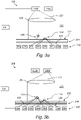
- supercritical angle fluorescence will be briefly described.
- fluorophores 100 can be described by dipoles that preferentially emit fluorescent light in certain axes depending on an orientation of the dipole.
- fluorophores 100 emit an evanescent non-propagating component.
- This non-propagating component becomes propagating when the fluorophore 100 is at or below a distance of one wavelength from an interface 102. This is called supercritical angle fluorescence (SAF) and is emitted above a critical angle (corresponding to total internal reflection) of the interface between two materials at different sides of an interface.
- SAF supercritical angle fluorescence
- the critical angle is defined by a relation of refractive index between the solution 104 (forming a first material on one side of the interface 102) and a material of the sample holder 106 (forming a second material on an opposite side of the interface 102).
- the material of the sample holder may typically be glass or plastic and may be selected in order to define a refractive index so as to select a critical angle formed in the interface 102.
- the SAF may thus propagate into the material of the sample holder 106 and may be further transferred through a second interface 108 between the sample holder 106 and another medium 110, if the refractive index of the other medium 110 is the same or higher than a refractive index of the material of the sample holder 106, i.e. total internal reflection will be avoided in an interface of the sample holder 106 and the other medium 110.
- a surface of the sample holder 106 or a surface of a detector for collecting SAF may thus be treated with a refractive index matching medium 110 in order to ensure that the supercritical angle fluorescent light may be collected.
- the surface treatment may be provided by means of a viscous material, such as an oil, so that it may be ensured that there is no air gap between the sample holder 106 and the detector.
- the intensity of SAF can be as high as 50% of the total fluorescence emitted from a sample, if the fluorophores 100 are arranged close to a surface. As illustrated in Fig. 2 , the intensity decreases with an almost exponential behaviour with increasing distance (d) from the interface 102. Thus, if detection of light is selective to SAF and not disturbed by undercritical angle fluorescence, a very high sensitivity to fluorophores 100 arranged close to a surface is obtained.
- Figs. 3a and 3b show a principle set-up of an apparatus (200) according to an embodiment.
- the apparatus is for detecting fluorescent light from a fluorophore 100 in a sample 130 present at an interface 132.
- the apparatus could be set up for detecting any type of photoluminescent particle at the interface 132.
- Aligned with the interface 132 is an interference filter 204 comprising a plurality of layers of at two materials having different refractive indices on top of an array 216 of photo-detectors 206a-h.
- the interference filter 204 is configured to selectively collect and transmit light towards the array 216 based on an angle of incidence of the light towards the interference filter 204.
- the interference filter 204 is further configured to selectively transmit supercritical angle light from the interface 132 in the sample 130 towards the array 216 and suppress undercritical angle light from the interface 132 in the sample 130.
- the apparatus 200 comprises two different light sources 210a, 210b.
- the second light source 210b is a laser configured for emitting light 120 of the emission wavelength of the fluorophore 100 that is to be detected
- the first light source 210a is a laser configured for emitting light of an excitation wavelength 122 of the of the fluorophore 100 that is to be detected.
- the control unit may also be for reading the output from the individual photo detectors 206a-h of the array 216.
- a reference or scattering profile of the sample 130 is first detected by illuminating the sample 130 with the second laser 210, i.e. with light 120 of the emission wavelength of the fluorophore 100.
- the emission light 120 does not excite the fluorophore 100, but a scattering particle 118 present at the interface 132 may scatter the incident light 120 in the supercritical angle region and this light 124 is detected by the photo-detector array 216.
- only a few of the individual photo-detectors receives incident light 124, in this case detectors 206c, 206d, 206f and 206g. The counts from these detectors may thus be used e.g. by the control unit 128 to generate a scattering profile of the array.
- the sample 130 is illuminated with light 122 having a wavelength that excites the fluorophore 100, as illustrated in Fig. 3b .
- This is performed using the first laser 210a, and emitted light 126 by the fluorophore in the supercritical region is detected by the photo-detector array 216.
- the emitted light 126 is detected by individual detectors 206a, 206b, 206e and 206f. Since scattering is less sensitive to wavelength than fluorescence, the scattering particle 118 may scatter light in the same way as during the excitation of the second wavelength, and the scattered light is detected by the same detectors as during the illumination with the light of the second wavelength.
- the photon counts during illumination with the first wavelength may be used by e.g. the control unit 128 to generate a combined profile comprising both a fluorescence profile and the scattering profile. Consequently, the fluorescence profile may be calculated or quantified by subtracting the photodetector counts from the first measurements, i.e. the scattering profile, from the photon counts from the second measurement, i.e. from the combined profile.
- the photodetector array 216 may further be used to collect spatial information in addition to the photon count.
- the control unit 128 may also be used for alternating between illumination with the first 210a and the second 210b lasers, thereby enabling measurements of the florescence at the interface 132 as a function of time with high temporal resolution. As an example, the control unit 128 may alternate between the two lasers at least every 100 ms.
- FIG. 4 an apparatus 200 for detecting fluorescent light emitted from a sample 202 will be described in further detail.
- the apparatus 200 comprises an interference filter 204.
- the interference filter 204 comprises a stack of layers for selectively transmitting light through the interference filter 204.
- the interference filter 204 may comprise a stack of alternating layers 204a, 204b of two different materials (having different refractive indices). In interfaces between layers in the interference filter 204, constructive interference may occur between light having travelled different path lengths through the interference filter 204 (different number of reflections in the interfaces between the layers).
- the refractive index and thickness of the layers 204a, 204b may thus control characteristics of light that will cause constructive interference. This implies that light that forms constructive interference in the interference filter 204 may be selectively transferred through the interference filter 204.
- the interference filter 204 may be designed such that light having a specific angle of incidence will be selectively transmitted through the interference filter 204. Hence, the interference filter 204 may selectively transmit SAF light, while suppressing undercritical angle fluorescence. Thus, the interference filter 204 may be configured to filter out SAF allowing the SAF to be detected with a high signal-to-noise ratio.
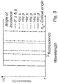
- the interference filter 204 may be designed such that a cut-off wavelength is defined, which is dependent on an angle of incidence of light on the interference filter 204.
- the chart in Fig. 5 illustrates the transmission by the interference filter 204 for different angles of incidence of light.
- Light incident at the critical angle ⁇ c will thus be transmitted if the wavelength is equal to or larger than the fluorescence wavelength. Since the fluorescence wavelength is larger than the excitation wavelength, this also implies that excitation light will not be passed through the interference filter 204.
- the interference filter 204 may be designed such that a cut-off wavelength for s-polarized light incident at the critical angle corresponds to the fluorescence wavelength.
- the apparatus 200 further comprises a photo-detector 206.
- the photo-detector 206 may be arranged to receive light having been transmitted by the interference filter 204.
- the photo-detector 206 may comprise at least one photo-sensitive area, which is configured to generate a response, such as an electric charge, in proportion to light incident on the photo-sensitive area. Thus, the photo-detector 206 may generate a measurement of intensity of light being transmitted through the interference filter 204.
- the photo-detector 206 may comprise a single or a few photo-sensitive areas, which may be configured to generally detect an intensity of SAF emitted by a sample. An output from the photo-detector 206 may then be used for quantitatively determining an amount of fluorophores 100 at a surface of the sample holder. However, the output may not necessarily determine an origin of the emitted light, such that the output may not be used for imaging of the sample. If a plurality of photo-sensitive areas is used, each may be configured to determine intensity of light emitted from a respective large region in the sample, such that the regions may be quantitatively compared.
- the photo-detector 206 may comprise an array of photo-sensitive areas.
- the array of photo-sensitive areas may be used for imaging of the sample, as each photo-sensitive area in the array may receive SAF originating from a specific part of the sample.
- the photo-detector 206 may for example be implemented as a charge-coupled device (CCD) or a complementary metal-oxide-semiconductor (CMOS) image sensor. Analog output from the photo-sensitive areas may pass an analog-to-digital converter, such that the photo-detector 206 may output a digital representation of detected light. The digital representation is then suited to be transferred to other entities for processing the detected SAF.
- CCD charge-coupled device
- CMOS complementary metal-oxide-semiconductor
- the interference filter 204 may be provided with a capping layer 208, which may protect the interference filter 204, e.g. against wear.
- the capping layer 208 may be formed on top of the interference filter 204.
- the apparatus 200 may be configured to receive a sample holder 106 such that the sample holder 106 is arranged on the capping layer 208. Alternatively, the sample holder 106 may be arranged directly on the interference filter 204.
- An upper surface of the capping layer 208 or (if no capping layer is provided) an upper surface of the top layer in the interference filter 204 may be treated such that a contact between the sample holder 106 and the interference filter 204 is formed through a refractive index matching medium, such as an oil. Thus, it may be ensured that SAF propagating through a wall of the sample holder 106 will be propagated further into the interference filter 204.
- the sample holder 106 may comprise walls, e.g. of glass or a plastic material, defining a cavity or space in which a fluidic sample may be provided.
- the sample holder 106 may thus function as a carrier for providing the sample in the apparatus 200.
- the sample holder 106 may comprise one or more pre-defined measurement sites 112.
- the sample holder 106 may thus comprise a first mask 114 arranged on an inner surface of a wall of the sample holder 106.
- the first mask 114 may have holes or apertures, allowing the sample to be in contact with a wall of the sample holder 106 such that SAF may be generated.
- the holes or apertures in the first mask 114 may thus form measurement sites 112.
- the first mask 114 may also be formed from a material blocking transmission of fluorescent light (and excitation light) in order to further prevent light not originating from measurement sites 112 to reach the photo-detector 206.
- the apparatus 200 may further comprise at least one light source 210, which is configured to emit excitation light towards a sample and light for gathering background noise information from said sample. As shown in Fig. 4 , in a first embodiment, the light source 210 may be provided to emit light through the sample.
- the at least one light source may be arranged for emitting both light of the first wavelength and the second wavelength through the sample.
- the light source 210 and the interference filter 204 are provided on opposite sides of the sample.
- This arrangement of the light source 210 may be convenient, as placement of the light source 210 does not interfere with placement of the interference filter 204 and photo-detector 206. Thus, a very simple set-up may be used.
- fluorophores 100 in a bulk solution of the sample may be excited and emit fluorescent light.
- the interference filter 204 only selectively transmitting light having an angle of incidence equal with or larger than the critical angle, fluorescence from the bulk solution will not be transmitted through the interference filter 204 towards the photo-detector 206.
- the light source 210 may be a laser providing light of a specific wavelength, which constitutes an excitation wavelength for enabling fluorescent light to be transmitted by the fluorophores 100.
- the light source 210 may be associated with a lens or other optical component for focusing excitation light to a spot in the sample close to the inner surface of a wall of the sample holder 106.
- a confocal arrangement may be provided, wherein the fluorophores 100 close to the surface are selectively excited (and also SAF from these fluorophores is selectively detected over bulk fluorescence).
- the confocal arrangement may be used for scanning over a lateral surface at the inner wall of the sample holder 106, such that different regions of the sample may be sequentially excited.
- the capping layer 208 may comprise a second mask 212.
- a wall of the sample holder 106 may be provided with the second mask 212.
- the second mask 212 may selectively block transmission of the excitation wavelength, while transmitting the fluorescence wavelength.
- the second mask 212 may be configured to absorb or reflect light of the excitation wavelength.
- the second mask 212 may be configured to have an inverted pattern to the first mask 114.
- the second mask 212 may extend over an entire surface of the sample holder 206 / interference filter 204.
- the second mask 212 may be arranged above or below the interference filter 204.
- the second mask 212 for blocking transmission of the excitation wavelength may be arranged within the interference filter 212, such as forming a layer in the stack of layers within the interference filter 204.
- the second mask 212 may be needed to avoid light from the light source 210 to leak through the interference filter 204.
- the blocking of the excitation light may be important as an intensity of the light transmitted by the light source 210 may be much stronger than an intensity of the SAF.
- the apparatus 200 may optionally further comprise a lens 214 between the interference filter 204 and the photo-detector 206.
- the lens 214 may direct light from the interference filter 204 towards being perpendicularly incident on the photo-sensitive area(s) of the photo-detector 206.
- the lens 214 may improve an intensity of light (number of photons) reaching the photo-detector 206 and also may improve the response to incident light (likelihood of an incident photon triggering a reaction in the photo-sensitive area).
- the photo-detector 206 and the interference filter 204 may be formed as an integrated detector package, optionally with the lens 214 arranged there between.
- the interference filter 204 may thus be formed directly on top a substrate comprising the photo-detector 206. This may be achieved by monolithically integrating the interference filter 204 on top of the photo-detector 206, such that the layers of the interference filter 204 are sequentially formed on the substrate comprising the photo-detector 206. Alternatively, the interference filter 204 may be separately manufactured before being integrated on top of the photo-detector 206.
- the photo-detector 206, the lens 214 and the interference filter 204 may be manufactured and arranged in the apparatus 200 as separate components.
- a refractive index matching medium needs to be provided between each of the components in order to prevent total internal reflections in any of the surfaces (which would otherwise severely affect detection of SAF).
- the interference filter 204 may be configured to be exchangeable in the apparatus.
- the interference filter 204 may be adapted to selectively transmit SAF of a specific wavelength and incident on the interference filter 204 at a specific angle.
- the apparatus 200 may be changed to work for a different wavelength of SAF and/or a different angle of incidence of the SAF on the interference filter 204.
- the apparatus 200 may be delivered with a set of interference filters 204 such that the apparatus 200 may be selectively configured to work for a set of different wavelengths of SAF and/or different angles of incidence of the SAF on the interference filter 204.
- the apparatus 200 may further comprise a light source 210 that may be controlled such that an appropriate excitation wavelength is emitted towards the sample.
- the apparatus 200 may comprise a set of parallel light sources 210 configured to emit different wavelengths, such that the appropriate light source 210 may be chosen depending on the desired excitation wavelength to be used.
- the apparatus 200 may comprise a housing 216, in which all components of the apparatus 200 are mounted.
- the housing 216 may provide a well-defined relationship between the light source 210 and the interference filter 204 and the photo-detector 206 so that a robust set-up for performing analyses on samples is provided.
- the housing 216 may also enclose all the components, which may imply that laser light emitted by the light source 210 is confined to the housing 216. Thus, the apparatus 200 may be used safely and a user of the apparatus 200 need not be specially trained in use of laser equipment.
- the apparatus 200 may further comprise a receiver for receiving a sample holder 106.
- the receiver may be movable to between a receiving position, in which the receiver may partially extend from the housing allowing the sample holder to be placed in the receiver, and an analysis position, in which the receiver may be arranged in the housing in order to place the sample holder 106 in a desired relation to the light source 210, the interference filter 204 and the photo-detector 206.
- the receiver may alternatively provide guiding surface(s) for guiding insertion of the sample holder 106 (e.g. through a slot in the housing 216) so that a sample is properly presented in an analysis position in the housing 216.
- components of the apparatus 200 may alternatively be separately manufactured and delivered.
- the apparatus 200 may thus be assembled when it is to be used.
- the light source 210, the interference filter 204 and the photo-detector 206 may each be separately manufactured.
- the interference filter 204 and the photo-detector 206 may form an integrated detector, which may be manufactured and sold as a separate piece of equipment. For advanced users, the integrated detector may then be used as a part in a self-assembled set-up allowing the user to make choices of light source and optical components to be used in the set-up.
- FIG. 6 a second embodiment of the apparatus 300 will be described.
- the discussion of features and components of the first embodiment apply to a large extent also to the second embodiment and the discussion will therefore not be repeated here for brevity. Rather, only the features that differ between the first and second embodiments will be discussed.
- the apparatus 300 of the second embodiment uses an evanescent field for providing excitation of the fluorophores 100.
- the apparatus 300 defines a light path associated with the light source 310.
- the light path may provide a surface in which total internal reflection of the excitation light may occur.
- the sample is arranged close to the total internal reflection surface and an evanescent light field in the vicinity of the total internal reflection surface may thus reach the sample and excite fluorophores 100.
- the apparatus 300 may comprise a waveguide 318, such that light from a light source 310 may propagate through the waveguide 318 by means of total internal reflection.
- the waveguide 318 may be arranged as a layer above the interference filter 304.
- a sample holder 106 may be arranged above the waveguide 318 in order to allow the evanescent excitation light to affect the sample.
- the waveguide 318 may form part of sample holder 106, such that the waveguide 318 may present a surface on which the sample is directly provided.
- evanescent light for excitation of fluorophores 100 implies that only fluorophores 100 close to a surface are excited. Further, the interference filter 304 ensures that only SAF is collected. This implies that the set-up of the second embodiment may provide a very good signal-to-noise ratio of detected light, as background noise may be very limited.
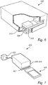
- the apparatus 200, 300 discussed above may advantageously be used in a biosensor system 400, as shown in Fig. 7 .
- the biosensor system 400 may comprise a sample holder 406 which may be specifically prepared for pre-processing a sample.
- the sample holder 406 may thus e.g. comprise a substance for reacting with a sample, such that the reaction may then be observed by the apparatus 200, 300.
- the sample holder 406 may also comprise fluorophores 100 which may selectively attach to targets in the sample for allowing the targets to be observed in the analysis performed by the apparatus.
- the apparatus of biosensor system 400 may comprise a receiver 407 for receiving the sample holder 406.
- a pre-processing of the sample in the sample holder 406 may depend on the desired analysis to be made.
- the pre-processing of the sample may operate to expose molecules of interest from within a cell or to protect the molecules of interest from other molecules that seek to destroy the molecules of interest when the molecules of interest leave the protection of the cell.
- the pre-processing may involve mixing detector antibodies (tagged with fluorophores) with the molecules of interest before the detector antibodies are brought in contact with capture antibodies that are bound to the surface of the sample holder.
- pre-processing of the sample may be performed in the sample holder 406 and that the pre-processing of the sample may depend on the specific type of analysis to be made.
- the biosensor system 400 may for instance be used for detecting (bio)molecules so as to determine presence of molecules of interest in a sample. Similarly, the biosensor system 400 may in other embodiments be used for detecting viruses in a sample. The biosensor system 400 may in yet other embodiments be used for cell membrane imaging.
- the biosensor system 400 may comprise a processing unit 420, which may be arranged within the housing of the apparatus 200, 300.
- the processing unit 420 may thus be configured to receive information from the photo-detector 206, e.g. in the form of a digital representation of detected light, so as to allow making an analysis.
- the processing unit may thus function as the control unit discussed in relation to Figs. 3a and 3b above.
- the processing unit 420 may also be configured to determine a biological measurement based on the received information.
- the processing unit 420 may alternatively be remote from the apparatus 200, 300.
- the apparatus 200, 300 may thus comprise a communication unit for wired or wireless communication with the processing unit 420.
- the communication unit may communicate the digital representation of detected light, or may communicate a pre-processed representation.
- the processing unit 420 may be any type of unit able to process information.
- the processing unit 420 may be a general-purpose processing unit, such as a central processing unit (CPU), which may be loaded with a computer program product in order to allow the processing unit 420 to perform the desired operations.
- the processing unit 420 may alternatively be a special-purpose circuitry for providing only specific logical operations.
- the processing unit 420 may be provided in the form of an application-specific integrated circuit (ASIC), an application-specific instruction-set processor (ASIP), a field-programmable gate array (FPGA), or a digital signal processor (DSP).
- ASIC application-specific integrated circuit
- ASIP application-specific instruction-set processor
- FPGA field-programmable gate array
- DSP digital signal processor
- Fig. 8 schematically illustrates a flow chart of an example of a method 500 of the present disclosure for detecting photoluminescent light emitted from a sample.
- the method of the invention is defined in appended claim 10.
- the method may be performed by an apparatus discussed herein above.
- the method 500 comprises providing 501 a sample comprising photoluminescent particles.
- the photoluminescent particles have an excitation wavelength corresponding to a first wavelength.
- the method further comprises emitting 502 light of a second wavelength towards the sample comprising photoluminescent particles and the second wavelength is selected so as not to excite said photoluminescent particles.
- the second wavelength may be selected so as to correspond to the emission wavelength of said photoluminescent particles.
- the method further comprises detecting 503 incident light corresponding to scattered light from the sample on a photo-detector during said emitting of light of the second wavelength.
- the method comprises emitting 504 light of said first wavelength towards said sample comprising photoluminescent particles, thereby exciting said fluorophores, and detecting 505 incident light corresponding to scattered light from the sample and photoluminescent light from the sample on the photodetector during said emitting of light of the first wavelength, wherein the scattered light and the photoluminescent light emitted from the sample passes an interference filter before reaching the photodetector, the interference filter being configured to selectively transmit supercritical angle light from the sample and suppress undercritical angle light from the sample.
- the method may further comprise repeating 506 said emitting of light of the second wavelength, said detecting of light corresponding to scattered light, said emitting of light of the first wavelength and said detecting of light corresponding to scattered light and photoluminescent light. Moreover, the method may comprise determining 507 the emitted light from said photoluminescent particles using the detected light from said detecting of light corresponding to scattered light and the detected light from said detecting of light corresponding to scattered light and photoluminescent light.
- a sample holder may be integrated with the interference filter and the photo-detector for providing a complete chip prepared for receiving a sample.
- the sample holder may be fused to the interference filter, such that refractive index matching medium is not needed between the interference filter and the sample holder.
- the sample holder is only used once (to avoid need of rinsing the sample holder), it may be desired to have an inexpensive, disposable sample holder. For such applications, having a sample holder integrated with the interference filter and the photo-detector may be less advantageous.
Landscapes
- Health & Medical Sciences (AREA)
- Physics & Mathematics (AREA)
- Life Sciences & Earth Sciences (AREA)
- Chemical & Material Sciences (AREA)
- Analytical Chemistry (AREA)
- Biochemistry (AREA)
- General Health & Medical Sciences (AREA)
- General Physics & Mathematics (AREA)
- Immunology (AREA)
- Pathology (AREA)
- Nuclear Medicine, Radiotherapy & Molecular Imaging (AREA)
- Investigating, Analyzing Materials By Fluorescence Or Luminescence (AREA)
Description
- The present disclosure relates to an apparatus for detecting photoluminescent light emitted from a sample. In particular, the disclosure relates to detecting supercritical angle fluorescent light. The present disclosure relates to a biosensor system making use of detection of supercritical angle photoluminescent light from a sample.
- Fluorescence is commonly used for studying samples in cell and molecular biology. The sample may be prepared by providing a fluorescent substance (fluorophore), that may be selectively bound to a part of the sample that is to be analyzed. Alternatively, an intrinsic fluorescence of the sample may be used in exciting fluorescent light from the sample.
- In diagnostic assays, target molecules and fluorophores are immobilized on a bottom surface of sample holder. A bulk solution may thus comprise a large number of fluorophores that may make it impossible to distinguish fluorescence from the target molecules from the bulk solution fluorescence. Thus, it may be necessary to wait a long time for the fluorophores in the bulk solution to settle to the surface before an analysis may be made. An alternative is to selectively analyze surface bound fluorophores. Thus, surface sensitive techniques are of special interest.
- It is presently known to use techniques for selectively exciting the fluorophores that are surface bound. For instance, using total internal reflection microscopy (TIRF), evanescent excitation may be used for exciting only a thin portion of a sample at the surface of the sample holder. The evanescent excitation is based on a small portion of light escaping a surface in which total internal reflection occurs and intensity of the light will very quickly decrease with distance from the surface. Thus, target molecules may be selectively excited in order to avoid fluorescent light of interest to be drowned by fluorescence from the bulk solution.
- The light emission of fluorophores can be described by an electrical dipole, which preferentially emits light in certain axes depending on orientation of the fluorophore. In addition to such propagation component of emitted light, fluorophores also have an evanescent non-propagating component. A part of this non-propagating component becomes propagating when the fluorophore is at or below a distance of one wavelength from a surface interface between two materials, specifically when the other material has a larger refractive index than the material that encloses the fluorophore. This is called supercritical angle fluorescence (SAF) and is emitted above the critical angle of the interface between the two materials.
- Thus, SAF phenomenon has been used together with TIRF in order to further improve resolution in imaging of portions of a sample close to a surface.
-
US 2016/0011112 A1 discloses a sample plate and an analyzing method, wherein the sample plate comprises a substrate, at least one sensor site on a first surface of the substrate and at least one optical element on a second surface of the substrate. The sample plate is further provided with a waveguide on the second surface for guiding an excitation signal to interact with the at least one sensor site. The method comprises bringing the sample in contact with at least one sensor site, exciting the sensor site in order to obtain an emitted signal, and selectively collecting the emitted signal by means of at least one optical element and utilizing a supercritical angle fluorescence method. The optical elements, which can be formed by diffractive elements or other integrated (e.g. Fresnel lens type) structures facilitating the collection of light emitted to the desired angles, collect the emitted light with the highest intensity, i.e. at/above the critical angle of total internal reflection. The light emitted at smaller angles is blocked by non-transparent/absorbing films/coatings/blockers on/under the bottom of the waveguide and to the other direction by the appropriate blockers and structures, e.g. reflective surfaces or diffractive elements. - However, the known devices using TIRF and SAF for exciting fluorophores at a surface and collecting light from the fluorophores requires bulky set-ups which may also be complex to manufacture. In addition, it may be desirable to use disposable sample holders, and such disposable sample holders should preferably be simple and very cheap to manufacture. The sample plate disclosed in
US 2016/0011112 A1 is complex and will not be cheap. -
US 2013/0236982 A1 discloses a sensor comprising a substrate having a first surface and a second surface. The first surface has at least one sensor site provided thereon. The substrate is configured such that on excitation of a sample provided at the sensor site, luminescence originating from the sesnsor site propagates into the substrate, the second surface of the substrate being configured to selectively transmit the luminescence propagating within the substrates at angles greater than the critical angle out of the substrate where it may be detected by a detector provided below the substrate. -
US 2017/0138859 A1 discloses a light-guide rod, a wavelength separation filter, and an optical sensor. Given the relationship between the angle of incidence and light intensity of fluorescence on a light reception surface of the optical sensor, the optical transmittance of the wavelength separation filter at the dominant wavelength of the rays of fluorescence incident on the light reception surface at a peak angle of incidence at which the light intensity is the highest is greater than the optical transmittance of the wavelength separation filter at the dominant wavelength of the rays of excitation light incident on the light reception surface at the peak angle of incidence and is higher than the optical transmittance of the wavelength separation filter at the dominant wavelength of the rays of fluorescence incident on the light reception surface at an angle of incidence of 0 DEG. -
US 2015/0090900 A1 discloses an optical sensor that may include multiple optical emitters configured to emit light into a fluid sample via an optical pathway. Light from the emitters can cause fluorescence from the sample and/or scatter off of the sample. Scattered and fluoresced light can be received by an optical detector in the sensor via the optical pathway, and used to determine at least one characteristic of the fluid sample. - Välimäki et al: "A novel platform for highly surface-sensitive fluorescent measurements applying simultaneous total internal reflection excitation and super critical angle detection", Chemical Physics Letters, Vol. 473, 2009, pp. 358-362, discloses a highly surface-sensitive fluorescent platform for chemical and biochemical analysis. The core component of the platform is a polystyrene parabolic lens that is utilised in simultaneous total internal reflection excitation and super critical angle fluorescence detection.
- It is an object of the invention to at least partly overcome one or more limitations of the prior art.
- The invention is defined in the independent claims. Preferred embodiments are set out in the dependent claims.
- As a first aspect of the invention, there is provided a biosensor system according to
claim 1, comprising - inter alia and as further defined with claim 1 - an apparatus for detecting photoluminescent light emitted from a sample. The apparatus further comprises - inter alia - a photo-detector for detecting light incident on the photo-detector; and
an interference filter arranged on the photo-detector, wherein the interference filter is configured to selectively collect and transmit light towards the photo-detector based on an angle of incidence of the light towards the interference filter, wherein the interference filter is configured to selectively transmit supercritical angle light from the sample towards the photo-detector and suppress undercritical angle light from the sample. - The apparatus enables an interference filter to be used for selectively transmitting light towards the photo-detector in dependence of angle of incidence of light on the interference filter. Thus, the interference filter is configured to pass supercritical angle photoluminescent light, while suppressing undercritical angle photoluminescent light. As an example, the interference filter may be configured to pass supercritical angle fluorescent light, while suppressing undercritical angle fluorescence. This implies that light emitted by fluorophores close to a surface, i.e. a surface of the sample holder is selectively passed towards the photo-detector, which enables the apparatus to detect light from fluorophores close to the surface with a high signal-to-noise ratio. In particular, fluorescence from a bulk solution may be suppressed and, hence, not disturb detection of light from fluorophores close to the surface.
- With the system according to the first aspect, it is possible to provide excitation light through the bulk solution. As photoluminescence such as fluorescence from the bulk solution is suppressed, the supercritical angle fluorescent light may still be detected. Thus, the light source and the photo-detector may be arranged on separate sides of the sample, which implies that a simple set-up may be provided (e.g. no waveguides may be required).
- Further, the use of an interference filter enables a compact and simple optical set-up for collection of light towards the photo-detector. In particular, no bulky optical components, such as lenses or mirrors for collecting the supercritical angle photoluminescent light is necessary.
- The interference filter being configured to selectively transmit supercritical angle fluorescence from the sample implies that the fluorescent sample is in contact or in close proximity (at a distance below a wavelength from a surface, e.g. <100 nm) to a substrate on which the interference filter is arranged.
- The system of the first aspect further provides for differentiating between scattered light and light emitted by the photoluminescent particles, thereby increasing the accuracy of the measurements. Since some biological material like cells may act as good scattering sites, it may be important to mitigate the background generated by excitation photons that get scattered above the critical angle. This will improve the sensitivity of the measurements. When a measurement of e.g. fluorescence has to be made, a reference measurement of scattering intensity may first be conducted using the second wavelength. After that, an excitation measurement may be conducted using the first wavelength of excitation light. Since scattering is a lot less sensitive to wavelength than fluorescence, the scattering is similar for both measurements and any additional signal that is detected when using the first wavelength, i.e. the excitation wavelength, may originate from the surface bound fluorophores. The fluorescence intensity can be quantified by subtracting the photodetector counts from the first measurement with those of the second measurement.
- Thus, in embodiments of the first aspect, the second wavelength has a value that enables detection of scattered light from said sample with the photo detector.
- According to the first aspect as defined with
claim 1, the second wavelength is at least 20 nm longer than the first wavelength. - Scattered light from the sample may be light that is scattered by other particles in the sample than the photoluminescent particles. The light scattered by the sample may have the same wavelength as the second wavelength. The scattered light may be detected by the photo detector after having passed the interference filter.
- In embodiments of the first aspect, the interference filter is further configured to selectively transmit supercritical angle light that is scattered, reflected or transmitted by the sample when it is illuminated by the second wavelength.
- Photoluminescent particles may be fluorophores, fluorescent particles or fluorescent molecules. The photoluminescent particles may also comprise phosphorescent molecules or phosphorescent particles. The photoluminescent particles may for example be cells or proteins labelled with a fluorophore or phosphorescent molecule.
- In embodiments of the first aspect, the apparatus further comprises a control unit configured for alternating the emitted light from said at least one light source between said first and second wavelengths.
- Thus, during measurements of a sample, the control unit may switch between the first and second wavelengths and thus enable a temporal resolution of the measurement. The control unit may be configured to alternate the emitted light at a rate that is higher than 1 Hz, such as higher than 2, Hz, such as higher than 5 Hz, such as about 10 Hz.
- Furthermore, the control unit may be configured for subtracting background information from the sample. Thus, the control unit may be configured for subtracting the signal detected when illuminating the sample with the second wavelength from the signal when illuminating the sample with the first wavelength.
- The at least one light source may comprise two separate light sources, such as two different lasers with different emission spectra or emission wavelength. Consequently, in embodiments of the first aspect said at least one light source comprises a first light source configured to emit light of said first wavelength and a second light source configured to emit light of said second wavelength.
- However, the at least one light source may be a single light source having at least two emission wavelengths (the first and second wavelength). Such a light source may for example be a LED or a laser tuned to different wavelengths, such as a broadband laser used in combination with at least one filter, such as a combination of high pass and low pass filters that may be alternated for emitting different wavelengths from the single light source.
- According to the first aspect of the invention, as defined with
claim 1, the second wavelength is at least 20 nm longer than said first wavelength, such as between 20-50 nm longer than said first wavelength. - The second wavelength may correspond to the emission wavelength of the photoluminescent particle that is to be detected.
- According to an embodiment, the light source is configured to emit a collimated light beam for exciting photoluminescent particles in a sample and wherein the apparatus is configured to receive a sample between the light source and the interference filter such that emitted light from the light source is transmitted through the sample before being collected by the interference filter.
- This provides for a simple set-up as the light source and the interference filter may be arranged on different sides of a sample. There is no need to design the apparatus (e.g. with waveguides) for allowing the light source and the interference filter to be arranged on a common side of the sample. Further, thanks to the selective collection of supercritical angle light, the analysis of surface bound targets will not be affected by e.g. fluorescence in the bulk solution, such that illumination through the sample may be used even if fluorophores in the bulk solution have not settled to the surface. This implies that the illumination through the sample may be used for real-time analysis.
- The apparatus further comprises a receiver for receiving a sample holder, wherein the receiver is configured to define a relation between a sample in the sample holder and the interference filter.
- The sample holder is thus for holding the sample comprising photoluminescent particles. Sample holders may be disposable and may be manufactured separately from the apparatus. Hence, the apparatus may not be provided with a sample holder when sold. However, the apparatus may comprise a receiver for providing a well-defined position of a sample holder, such that a sample will be provided in a desired relation to the interference filter and the photo-detector when an analysis is to be made.
- As an example, the receiver may be configured to define the relation between an interface in said sample holder and said interference filter, wherein said interference filter is configured to selectively transmit supercritical angle light emitted from photoluminescent particles at said interface towards the photo-detector and further configured to suppress undercritical angle light emitted from photoluminescent particles at said interface.
- The interface may be a solid surface. The sample holder may thus comprise a chamber having at least one inner surface, and the measurement may be for analyzing photoluminescent particles at the surface in the sample holder.
- As an example, the receiver may be configured to align said interface in said sample holder parallel to said interference filter. Thus, the receiver may be for aligning a sensor surface in the sample holder with the interference filter, e.g. such they are parallel, i.e. having normal vectors pointing in the same direction.
- Further, a top surface of the substrate onto which the interference filter is arranged or a bottom surface of a sample holder may be prepared with a refractive index matching medium to control refractive index of mediums that the supercritical angle fluorescent light is transmitted through. For instance, a viscous medium such as an oil, may be used as the refractive index matching medium. The supercritical angle fluorescent light produces an evanescent wave into the medium of the sample holder. The interface between the sample and the medium of the sample holder defines a critical angle corresponding to an angle at which light incident on the interface from the medium of the sample holder will be subject to total internal reflection (as a refractive index of the medium of the sample holder is larger than a refractive index of the sample). The supercritical angle fluorescent light propagates through the medium of the sample holder at an angle at or above the critical angle. The arrangement of a refractive index matching medium with higher refractive index than the medium of the sample holder allows the supercritical angle fluorescent light to be transmitted into the refractive index matching medium and ensures that the supercritical angle fluorescent light will not be subject to total internal reflection in the interface between the medium of the sample holder and the refractive index matching medium. Thus, an air interface to the sample holder should be avoided and, hence, using a refractive index matching medium may facilitate collection of the supercritical angle fluorescence.
- As mentioned above, the sample holder may be prepared with a refractive index matching medium for providing a suitable interface to the substrate comprising the interference filter. This implies that the apparatus need not be pre-configured with a refractive index matching medium. As a further alternative, the apparatus may be prepared with a refractive index matching medium before use of the apparatus. Furthermore, the receiver may comprise a movable carrier on which a sample holder may be placed. Thus, the receiver could, for instance, be arranged to move to a sample holder receiving position, wherein the receiver may partly extend outside a housing of the apparatus for receiving the sample holder. The receiver may further move to an analysis position, wherein the sample holder is arranged to present a sample for analysis inside the housing of the apparatus. This implies that the apparatus may comprise a closed housing during analysis, which may be advantageous for a secure use of the apparatus, in particular as a laser source may be used for providing the excitation light. Also, having a closed housing during analysis may prevent contamination of the sample during analysis such that reliable results may be obtained.
- The sample holder may be prepared for providing a pre-processing of the sample before analysis of the sample in the apparatus. Thus, the sample holder may comprise substance(s) for reacting with a sample when the sample is introduced into the sample holder. The sample holder may thus be adapted to a specific type of analysis that may require a specific pre-processing of the sample.
- A pre-processing of the sample may depend on the desired analysis to be made. Thus, the pre-processing of the sample may operate to expose molecules of interest from within a cell or to protect the molecules of interest from other molecules that seek to destroy the molecules of interest when the molecules of interest leave the protection of the cell. The pre-processing may involve mixing detector antibodies (tagged with fluorophores) with the molecules of interest before the detector antibodies are brought in contact with capture antibodies that are bound to the surface of the sample holder.
- It should be realized that many other types of pre-processing of the sample may be performed in the sample holder and that the pre-processing of the sample may depend on the specific type of analysis to be made.
- According to an alternative, the sample may be pre-processed before being introduced into the sample holder. This implies that the sample holder may merely provide a space for receiving a sample and presenting the sample for analysis, such that the sample holder may be very simple and, hence, inexpensive. However, it may be preferable to perform pre-processing of the sample in the sample holder, since this may also facilitate analyzing the sample during a reaction occurring in the sample holder such that the reaction may be followed in real-time. Further, pre-processing the sample before introducing the sample into the sample holder may cause a risk that external contaminants are introduced into the apparatus, so pre-processing of the sample outside the sample holder may need to be performed in a sterile manner.
- The interference filter may be arranged on the photo-detector by means of the interference filter being integral, e.g. monolithically integrated, with a substrate on which the photo-detector is formed. However, the interference filter and the photo-detector may be separately manufactured and the interference filter may be attached or connected to the photo-detector after manufacture of the separate components. In such case, a refractive index matching medium may also be arranged between the interference filter and the photo-detector in order to ensure that light transmitted through the interference filter reaches the photo-detector. The refractive index matching medium may ensure that supercritical angle fluorescence is only guided through layers with a refractive index that is larger than (or equal to) the refractive index of the layer the sample is in contact with in order to avoid total internal reflection in any interface that the supercritical angle fluorescent light passes.
- In embodiments of the first aspect, the interference filter comprises a plurality of layers of at least two materials having different refractive indices for selectively transmitting light in dependence of wavelength of the light and angle of incidence of the light.
- The interference filter may selectively transmit light based on interference effects that occurs between incident and reflected waves in interfaces between the layers of the interference filters. The interference filter may thus selectively transmit light based on dependence of wavelength of the light and angle of incidence of the light. This implies that the interference filter may transmit supercritical angle fluorescence while suppressing undercritical angle fluorescence and also suppressing excitation light incident on the interference filter.
- Since the interference filter may be configured to transmit light in dependence of both wavelength of light and angle of incidence of light, the interference filter may be configured to transmit supercritical angle fluorescence while suppressing undercritical angle fluorescence for a specific set-up of fluorescence wavelength and critical angle (given by the relation between refractive indices of the sample and the medium the sample holder). A specific set-up of fluorescence wavelength and angle of incidence of light may be used in several different types of analyses (e.g. using the same type of fluorophore), so the apparatus need not be limited to use for a single type of sample analysis.
- Further, the interference filter of the apparatus may be configured to be exchangeable. Thus, the apparatus may be delivered together with a set of interference filters, each adapted for selectively transmitting supercritical angle fluorescence of a specific wavelength and angle of incidence. A user of the apparatus may then be able to change the interference filter such that an appropriate interference filter for the analysis to be made is always installed in the apparatus.
- When the interference filter is to be exchangeable, the interference filter may preferably be a separate entity from the photo-detector and may be mounted in the apparatus separately from the photo-detector. The interference filter may thus be exchanged without a need to simultaneously exchange the photo-detector.
- Different fluorescence wavelengths may also be associated with different excitation wavelengths. The apparatus may thus comprise a light source that may be controlled such that an appropriate excitation wavelength is emitted towards the sample or a set of parallel light sources configured to emit different wavelengths, such that the appropriate light source may be chosen depending on the desired excitation wavelength to be used.
- According to an embodiment, the interference filter is integrally arranged on a substrate comprising the photo-detector. For instance, the interference filter may be monolithically integrated with the substrate. This implies that a fixed relationship with the photo-detector may be obtained, such that transmission of light from the interference filter to the photo-detector may be controlled by the fixed relationship. This implies that a well-defined set-up is provided, such that the apparatus is robust.
- According to an embodiment, the apparatus further comprises an absorptive layer for selectively absorbing photons of the first wavelength. The absorptive layer may be arranged to selectively absorb photons of the first wavelength that have passed the sample. This is advantageous in that it may reduce the amount of excitation light that passes the interference filter and reaches the photo-detector, which thus decreases the risk of saturating the photodetector.
- As an example, the absorptive layer may be arranged above or below the interference filter, i.e. upstream or downstream of the interference filter as seen in the light path from the light source to the photo-detector.
- Alternatively, the absorptive layer may be arranged within the interference filter, such as within the stack of layers forming a plurality of layers of at least two materials having different refractive indices, as discussed above.
- According to an embodiment, the apparatus further comprising a lens, which is arranged between the interference filter and the photo-detector, wherein the lens is configured to redirect light from the interference filter towards being incident parallel to a normal of a surface of the photo-detector. The lens may accurately control an origin of the supercritical fluorescence light that reaches the photo-detector. In particular, if an array of photo-sensitive areas is provided in the photo-detector, the detection of supercritical angle fluorescent light may be used for imaging the sample.
- The lens may be connected to the layers of the interference filter, such that the lens and the interference filter may form a single stack of layers. Additionally or alternatively, a medium may be provided between the interference filter and the lens, and between the lens and the photo-detector, in order to avoid total internal reflection in interfaces of a light path which may otherwise destroy a possibility of detecting the supercritical angle fluorescence.
- In embodiments of the first aspect, the photo-detector comprises an array of photo-sensitive areas, wherein each photo-sensitive area separately detects an amount of light incident on the photo-sensitive area.
- The array of photo-sensitive areas may be used for forming an image of the sample, as the different photo-sensitive areas of the photo-detector may receive light originating from different parts of the sample. It should be realized that the apparatus could be configured for imaging of a sample (having an array of photo-sensitive areas) or for quantitative analysis of an amount of supercritical fluorescent light from a sample (which would not require spatial resolution of the sample), wherein a single photo-sensitive area may be used.
- Samples having strong scattering may saturate a single photo-detector. However, when using an array of photo sensitive areas, any saturated photo-sensitive areas may be excluded afterwards when analyzing the output from the photo-detector.
- According to an embodiment, the apparatus further comprises a mask arranged on the interference filter, wherein the mask is configured to block transmission of light of the excitation wavelength. The mask may be arranged to block excitation light that passes unaffected through the sample, so as to ensure that the excitation light is not transmitted to the photo-detector. Since supercritical angle fluorescence is transmitted at an angle, the mask will not block the supercritical angle fluorescence.
- According to an embodiment, a capping layer is arranged on the interference filter, the capping layer forming a surface for receiving a sample and defining a desired critical angle for light from a sample being arranged on the capping layer. Thus, a structure for receiving a sample may be integrated with the interference filter. Arranging a capping layer for receiving a sample on top of the interference filter may imply that there is no need for a refractive index matching medium between a sample holder and the interference filter. However, this may imply that the entire structure of the capping layer, the interference filter and the photo-detector may become disposable (or that rinsing may be needed between sequential analyses).
- According to an embodiment, the light source comprises a waveguide having a total internal reflection surface for transporting light by total internal reflection in the waveguide, wherein the light source is configured for exciting fluorophores in a sample by evanescent light escaping the total internal reflection surface.
- This implies that both excitation of fluorophores and collection of emitted fluorescent light may be selective to fluorophores arranged at or close to a surface of a sample holder. The selective excitation may thus further act to improve a signal-to-noise ratio of detected light for light emitted from fluorophores at or close to the surface.
- According to an embodiment, the apparatus further comprises a lens for focusing excitation light towards a point in the sample. Thus, a confocal arrangement may be provided for selective excitation of fluorophores. A focusing of excitation light using a lens may have a smaller depth resolution compared to using evanescent light from total internal reflection. However, the use of a lens for focusing of excitation light may advantageously be used for selectively exciting fluorophores in a lateral position (in a plane of the surface on which the sample is arranged).
- According to an embodiment, the apparatus further comprises a scanning element for scanning the focused light over the sample for imaging of the sample. Thus, the excitation light may be used for selecting a part of the sample that is to be excited, such that the detected light originates from only the selected part of the sample. This may be used for imaging of the sample while using a single photo-detector for detecting light, without the photo-detector providing any spatial resolution.
- According to another aspect of the present inventive concept there is provided a method for detecting photoluminescent light emitted from a sample, according to independent method claim 10.
- This aspect may generally present the same or corresponding advantages as the former aspect. Effects and features of this second aspect are largely analogous to those described above in connection with the first and second aspects. Embodiments mentioned in relation to the first aspects are largely compatible with the second aspect.
- The method may be performed using an apparatus according to the first aspect described herein above. Step b) may thus be for detecting scattering light whereas step d) is used for detecting photoluminescent light, such as fluorescent light.
- In embodiments of the second aspect, the emitting of light of the first wavelength is performed less than 500 ms after said emitting of light of the second wavelength.
- Thus, when a measurement has to be made, the reference or scattering intensity may first be detected using the second wavelength, and immediately after, such as within a time period that is about 100 ms or less, an excitation measurement is performed using the first wavelength.
- As an alternative, steps b) and c) may be performed multiple times to collect a number of data points related to the scattering profile before step d) is performed, i.e. before emitting the excitation wavelength. This may be used if the scattering profile of the sample is not going to change rapidly.
- In embodiments of the second aspect, the method is further comprising repeating said emitting of light of the second wavelength, said detecting of light corresponding to scattered light, said emitting of light of the first wavelength and said detecting of light corresponding to scattered light and photoluminescent light.
- The method may thus comprise detecting both the scattering profile and the intensity profile from the photoluminescent particles as a function of time. The method may comprise scanning a sample, such as an interface, and repeating steps b) - e) at every scanned sample point.
- In embodiments of the second aspect, the method is further comprising determining the emitted light from said photoluminescent particles using the detected light from said detecting of light corresponding to scattered light and the detected light from said detecting of light corresponding to scattered light and photoluminescent light.
- Thus, the photoluminescent light, such as a fluorescence, may be quantified by subtracting the photo-detector counts from the first measurement using the first wavelength from the photo-detector counts from the second measurements using the second wavelength. In other words, the scattering profile may be subtracted from the profile including both scattering light and light from the photoluminescent particles.
- In embodiments of the second aspect, the second wavelength corresponds to the emission wavelength of said photoluminescent particles. The emission wavelength has a higher energy than the excitation wavelength, i.e. it should not generate any photoluminescence, but it is still close enough to the first wavelength, i.e. the excitation wavelength, so that the detected scattering profiles should be similar.
- The biosensor system may allow analyzing of a sample using a simple set-up which does not necessitate that targets bound to a surface are selectively illuminated with excitation light.
- The sample holder may be configured for pre-processing the sample, such as including a substance that is arranged to react with the sample. The biosensor system may be configured for real-time analysis of the sample, e.g. while a process of the sample reacting with a substance of the sample holder is occurring.
- The biosensor system could be used for detecting (bio)molecules so as to determine presence of molecules of interest in a sample. Similarly, the biosensor system may in other embodiments be used for detecting viruses. The biosensor system may in other embodiments be used for cell membrane imaging.
- According to an embodiment, the biosensor system further comprises a processing unit, which is configured to receive information of detected light from the photo-detector and to determine a biological measurement based on the received information.
- The processing unit may be the same as the control unit discussed in relation to the first aspect above.
- Thus, the biosensor system may be configured to provide biological measurement results based on detected light by the photo-detector.
- The processing unit may be remotely arranged from the apparatus. Thus, the apparatus may comprise a communication unit, e.g. for wired or wireless communication, for communicating information from the photo-detector to the processing unit. The processing unit may be provided on a computing unit connected to a network, such that the communication may take place via the network.
- The above, as well as additional objects, features and advantages of the present inventive concept, will be better understood through the following illustrative and non-limiting detailed description, with reference to the appended drawings. In the drawings like reference numerals will be used for like elements unless stated otherwise.
-
Fig. 1 is a schematic view illustrating supercritical angle fluorescence. -
Fig. 2 is a chart illustrating intensity of supercritical angle fluorescence as a function of distance of a fluorophore from a surface. -
Fig. 3 is a schematic illustration of the concept of the apparatus. -
Fig. 4 is a schematic view of an apparatus according to a first embodiment. -
Fig. 5 is a chart illustrating transmission by an interference filter in dependence of an angle of incidence of light. -
Fig. 6 is a schematic view of an apparatus according to a second embodiment. -
Fig. 7 is a schematic view of a biosensor system. -
Fig. 8 is a schematic view of a method according to the present disclosure. - An apparatus for detecting photoluminescent light emitted from a sample is provided. The apparatus is configured to detect supercritical angle fluorescent light. Before embodiments of the apparatus will be described in detail, supercritical angle fluorescence will be briefly described.
- Referring now to
Fig. 1 ,fluorophores 100 can be described by dipoles that preferentially emit fluorescent light in certain axes depending on an orientation of the dipole. In addition to this propagating component,fluorophores 100 emit an evanescent non-propagating component. This non-propagating component becomes propagating when thefluorophore 100 is at or below a distance of one wavelength from aninterface 102. This is called supercritical angle fluorescence (SAF) and is emitted above a critical angle (corresponding to total internal reflection) of the interface between two materials at different sides of an interface. For example, if thefluorophore 100 is present in a solution of a sample arranged in a sample holder, the critical angle is defined by a relation of refractive index between the solution 104 (forming a first material on one side of the interface 102) and a material of the sample holder 106 (forming a second material on an opposite side of the interface 102). The material of the sample holder may typically be glass or plastic and may be selected in order to define a refractive index so as to select a critical angle formed in theinterface 102. - The SAF may thus propagate into the material of the
sample holder 106 and may be further transferred through asecond interface 108 between thesample holder 106 and another medium 110, if the refractive index of theother medium 110 is the same or higher than a refractive index of the material of thesample holder 106, i.e. total internal reflection will be avoided in an interface of thesample holder 106 and theother medium 110. A surface of thesample holder 106 or a surface of a detector for collecting SAF may thus be treated with a refractive index matching medium 110 in order to ensure that the supercritical angle fluorescent light may be collected. For instance, the surface treatment may be provided by means of a viscous material, such as an oil, so that it may be ensured that there is no air gap between thesample holder 106 and the detector. - The intensity of SAF can be as high as 50% of the total fluorescence emitted from a sample, if the
fluorophores 100 are arranged close to a surface. As illustrated inFig. 2 , the intensity decreases with an almost exponential behaviour with increasing distance (d) from theinterface 102. Thus, if detection of light is selective to SAF and not disturbed by undercritical angle fluorescence, a very high sensitivity to fluorophores 100 arranged close to a surface is obtained. -
Figs. 3a and 3b show a principle set-up of an apparatus (200) according to an embodiment. The apparatus is for detecting fluorescent light from afluorophore 100 in asample 130 present at aninterface 132. However, the apparatus could be set up for detecting any type of photoluminescent particle at theinterface 132. Aligned with theinterface 132 is aninterference filter 204 comprising a plurality of layers of at two materials having different refractive indices on top of anarray 216 of photo-detectors 206a-h. Theinterference filter 204 is configured to selectively collect and transmit light towards thearray 216 based on an angle of incidence of the light towards theinterference filter 204. Theinterference filter 204 is further configured to selectively transmit supercritical angle light from theinterface 132 in thesample 130 towards thearray 216 and suppress undercritical angle light from theinterface 132 in thesample 130. - The
apparatus 200 comprises twodifferent light sources light source 210b is a laser configured for emitting light 120 of the emission wavelength of thefluorophore 100 that is to be detected, whereas thefirst light source 210a is a laser configured for emitting light of anexcitation wavelength 122 of the of thefluorophore 100 that is to be detected. There is further acollimating lens 116 arranged in the light path between thelight sources light sources control unit 128 configured for alternating the illumination of thesample 130 between the emitted light from thefirst light source 210a and the emitted light from the secondlight source 210b. The control unit may also be for reading the output from theindividual photo detectors 206a-h of thearray 216. - During a measurement, a reference or scattering profile of the
sample 130 is first detected by illuminating thesample 130 with thesecond laser 210, i.e. withlight 120 of the emission wavelength of thefluorophore 100. This is illustrated inFig. 3a . Theemission light 120 does not excite thefluorophore 100, but ascattering particle 118 present at theinterface 132 may scatter the incident light 120 in the supercritical angle region and this light 124 is detected by the photo-detector array 216. As illustrated inFig. 3a , only a few of the individual photo-detectors receivesincident light 124, in thiscase detectors control unit 128 to generate a scattering profile of the array. - After excitation with the
second laser 210b, thesample 130 is illuminated with light 122 having a wavelength that excites thefluorophore 100, as illustrated inFig. 3b . This is performed using thefirst laser 210a, and emitted light 126 by the fluorophore in the supercritical region is detected by the photo-detector array 216. In this example, the emittedlight 126 is detected byindividual detectors scattering particle 118 may scatter light in the same way as during the excitation of the second wavelength, and the scattered light is detected by the same detectors as during the illumination with the light of the second wavelength. The photon counts during illumination with the first wavelength may be used by e.g. thecontrol unit 128 to generate a combined profile comprising both a fluorescence profile and the scattering profile. Consequently, the fluorescence profile may be calculated or quantified by subtracting the photodetector counts from the first measurements, i.e. the scattering profile, from the photon counts from the second measurement, i.e. from the combined profile. - The
photodetector array 216 may further be used to collect spatial information in addition to the photon count. Thecontrol unit 128 may also be used for alternating between illumination with the first 210a and the second 210b lasers, thereby enabling measurements of the florescence at theinterface 132 as a function of time with high temporal resolution. As an example, thecontrol unit 128 may alternate between the two lasers at least every 100 ms. - Referring now to
Fig. 4 , anapparatus 200 for detecting fluorescent light emitted from a sample 202 will be described in further detail. - The
apparatus 200 comprises aninterference filter 204. Theinterference filter 204 comprises a stack of layers for selectively transmitting light through theinterference filter 204. Theinterference filter 204 may comprise a stack of alternatinglayers interference filter 204, constructive interference may occur between light having travelled different path lengths through the interference filter 204 (different number of reflections in the interfaces between the layers). The refractive index and thickness of thelayers interference filter 204 may be selectively transferred through theinterference filter 204. - The
interference filter 204 may be designed such that light having a specific angle of incidence will be selectively transmitted through theinterference filter 204. Hence, theinterference filter 204 may selectively transmit SAF light, while suppressing undercritical angle fluorescence. Thus, theinterference filter 204 may be configured to filter out SAF allowing the SAF to be detected with a high signal-to-noise ratio. - As indicated in
Fig. 5 , theinterference filter 204 may be designed such that a cut-off wavelength is defined, which is dependent on an angle of incidence of light on theinterference filter 204. The chart inFig. 5 illustrates the transmission by theinterference filter 204 for different angles of incidence of light. Light incident at the critical angle θc will thus be transmitted if the wavelength is equal to or larger than the fluorescence wavelength. Since the fluorescence wavelength is larger than the excitation wavelength, this also implies that excitation light will not be passed through theinterference filter 204. - However, as also indicated in
Fig. 5 , there is a difference in cut-off wavelength for s-polarized and p-polarized light. Thus, theinterference filter 204 may be designed such that a cut-off wavelength for s-polarized light incident at the critical angle corresponds to the fluorescence wavelength. - The
apparatus 200 further comprises a photo-detector 206. The photo-detector 206 may be arranged to receive light having been transmitted by theinterference filter 204. - The photo-
detector 206 may comprise at least one photo-sensitive area, which is configured to generate a response, such as an electric charge, in proportion to light incident on the photo-sensitive area. Thus, the photo-detector 206 may generate a measurement of intensity of light being transmitted through theinterference filter 204. - The photo-
detector 206 may comprise a single or a few photo-sensitive areas, which may be configured to generally detect an intensity of SAF emitted by a sample. An output from the photo-detector 206 may then be used for quantitatively determining an amount offluorophores 100 at a surface of the sample holder. However, the output may not necessarily determine an origin of the emitted light, such that the output may not be used for imaging of the sample. If a plurality of photo-sensitive areas is used, each may be configured to determine intensity of light emitted from a respective large region in the sample, such that the regions may be quantitatively compared. - In an alternative embodiment, the photo-
detector 206 may comprise an array of photo-sensitive areas. The array of photo-sensitive areas may be used for imaging of the sample, as each photo-sensitive area in the array may receive SAF originating from a specific part of the sample. - The photo-
detector 206 may for example be implemented as a charge-coupled device (CCD) or a complementary metal-oxide-semiconductor (CMOS) image sensor. Analog output from the photo-sensitive areas may pass an analog-to-digital converter, such that the photo-detector 206 may output a digital representation of detected light. The digital representation is then suited to be transferred to other entities for processing the detected SAF. - The
interference filter 204 may be provided with acapping layer 208, which may protect theinterference filter 204, e.g. against wear. Thecapping layer 208 may be formed on top of theinterference filter 204. Theapparatus 200 may be configured to receive asample holder 106 such that thesample holder 106 is arranged on thecapping layer 208. Alternatively, thesample holder 106 may be arranged directly on theinterference filter 204. - An upper surface of the
capping layer 208 or (if no capping layer is provided) an upper surface of the top layer in theinterference filter 204 may be treated such that a contact between thesample holder 106 and theinterference filter 204 is formed through a refractive index matching medium, such as an oil. Thus, it may be ensured that SAF propagating through a wall of thesample holder 106 will be propagated further into theinterference filter 204. - The
sample holder 106 may comprise walls, e.g. of glass or a plastic material, defining a cavity or space in which a fluidic sample may be provided. Thesample holder 106 may thus function as a carrier for providing the sample in theapparatus 200. - The
sample holder 106 may comprise one or morepre-defined measurement sites 112. Thesample holder 106 may thus comprise afirst mask 114 arranged on an inner surface of a wall of thesample holder 106. Thefirst mask 114 may have holes or apertures, allowing the sample to be in contact with a wall of thesample holder 106 such that SAF may be generated. The holes or apertures in thefirst mask 114 may thus formmeasurement sites 112. Thefirst mask 114 may also be formed from a material blocking transmission of fluorescent light (and excitation light) in order to further prevent light not originating frommeasurement sites 112 to reach the photo-detector 206. - The
apparatus 200 may further comprise at least onelight source 210, which is configured to emit excitation light towards a sample and light for gathering background noise information from said sample. As shown inFig. 4 , in a first embodiment, thelight source 210 may be provided to emit light through the sample. - The at least one light source may be arranged for emitting both light of the first wavelength and the second wavelength through the sample.
- Thus, the
light source 210 and theinterference filter 204 are provided on opposite sides of the sample. - This arrangement of the
light source 210 may be convenient, as placement of thelight source 210 does not interfere with placement of theinterference filter 204 and photo-detector 206. Thus, a very simple set-up may be used. - Since light from the
light source 210 is transmitted through the sample,fluorophores 100 in a bulk solution of the sample may be excited and emit fluorescent light. However, thanks to theinterference filter 204 only selectively transmitting light having an angle of incidence equal with or larger than the critical angle, fluorescence from the bulk solution will not be transmitted through theinterference filter 204 towards the photo-detector 206. - The
light source 210 may be a laser providing light of a specific wavelength, which constitutes an excitation wavelength for enabling fluorescent light to be transmitted by thefluorophores 100. - The
light source 210 may be associated with a lens or other optical component for focusing excitation light to a spot in the sample close to the inner surface of a wall of thesample holder 106. Thus, a confocal arrangement may be provided, wherein thefluorophores 100 close to the surface are selectively excited (and also SAF from these fluorophores is selectively detected over bulk fluorescence). - The confocal arrangement may be used for scanning over a lateral surface at the inner wall of the
sample holder 106, such that different regions of the sample may be sequentially excited. - The
capping layer 208 may comprise asecond mask 212. Alternatively, a wall of thesample holder 106 may be provided with thesecond mask 212. Thesecond mask 212 may selectively block transmission of the excitation wavelength, while transmitting the fluorescence wavelength. For instance, thesecond mask 212 may be configured to absorb or reflect light of the excitation wavelength. Thesecond mask 212 may be configured to have an inverted pattern to thefirst mask 114. Alternatively, thesecond mask 212 may extend over an entire surface of thesample holder 206 /interference filter 204. As an example, thesecond mask 212 may be arranged above or below theinterference filter 204. Alternatively, thesecond mask 212 for blocking transmission of the excitation wavelength may be arranged within theinterference filter 212, such as forming a layer in the stack of layers within theinterference filter 204. - Since the excitation light is transmitted by the
light source 210 directly towards theinterference filter 204, thesecond mask 212 may be needed to avoid light from thelight source 210 to leak through theinterference filter 204. The blocking of the excitation light may be important as an intensity of the light transmitted by thelight source 210 may be much stronger than an intensity of the SAF. - The
apparatus 200 may optionally further comprise alens 214 between theinterference filter 204 and the photo-detector 206. Thelens 214 may direct light from theinterference filter 204 towards being perpendicularly incident on the photo-sensitive area(s) of the photo-detector 206. Thus, thelens 214 may improve an intensity of light (number of photons) reaching the photo-detector 206 and also may improve the response to incident light (likelihood of an incident photon triggering a reaction in the photo-sensitive area). - The photo-
detector 206 and theinterference filter 204 may be formed as an integrated detector package, optionally with thelens 214 arranged there between. - The
interference filter 204 may thus be formed directly on top a substrate comprising the photo-detector 206. This may be achieved by monolithically integrating theinterference filter 204 on top of the photo-detector 206, such that the layers of theinterference filter 204 are sequentially formed on the substrate comprising the photo-detector 206. Alternatively, theinterference filter 204 may be separately manufactured before being integrated on top of the photo-detector 206. - According to an alternative embodiment, the photo-
detector 206, thelens 214 and theinterference filter 204 may be manufactured and arranged in theapparatus 200 as separate components. However, in such case, a refractive index matching medium needs to be provided between each of the components in order to prevent total internal reflections in any of the surfaces (which would otherwise severely affect detection of SAF). - Further, in an embodiment, the
interference filter 204 may be configured to be exchangeable in the apparatus. Theinterference filter 204 may be adapted to selectively transmit SAF of a specific wavelength and incident on theinterference filter 204 at a specific angle. Thus, by changing theinterference filter 204, theapparatus 200 may be changed to work for a different wavelength of SAF and/or a different angle of incidence of the SAF on theinterference filter 204. - Thus, the
apparatus 200 may be delivered with a set ofinterference filters 204 such that theapparatus 200 may be selectively configured to work for a set of different wavelengths of SAF and/or different angles of incidence of the SAF on theinterference filter 204. - As a different fluorescence wavelength often may require different excitation wavelengths, the
apparatus 200 may further comprise alight source 210 that may be controlled such that an appropriate excitation wavelength is emitted towards the sample. Alternatively, theapparatus 200 may comprise a set of parallellight sources 210 configured to emit different wavelengths, such that the appropriatelight source 210 may be chosen depending on the desired excitation wavelength to be used. - The
apparatus 200 may comprise ahousing 216, in which all components of theapparatus 200 are mounted. Thehousing 216 may provide a well-defined relationship between thelight source 210 and theinterference filter 204 and the photo-detector 206 so that a robust set-up for performing analyses on samples is provided. - The
housing 216 may also enclose all the components, which may imply that laser light emitted by thelight source 210 is confined to thehousing 216. Thus, theapparatus 200 may be used safely and a user of theapparatus 200 need not be specially trained in use of laser equipment. - The
apparatus 200 may further comprise a receiver for receiving asample holder 106. The receiver may be movable to between a receiving position, in which the receiver may partially extend from the housing allowing the sample holder to be placed in the receiver, and an analysis position, in which the receiver may be arranged in the housing in order to place thesample holder 106 in a desired relation to thelight source 210, theinterference filter 204 and the photo-detector 206. - The receiver may alternatively provide guiding surface(s) for guiding insertion of the sample holder 106 (e.g. through a slot in the housing 216) so that a sample is properly presented in an analysis position in the
housing 216. - It should be realized that components of the
apparatus 200 may alternatively be separately manufactured and delivered. Theapparatus 200 may thus be assembled when it is to be used. Thus, thelight source 210, theinterference filter 204 and the photo-detector 206 may each be separately manufactured. - As mentioned above, in a specific embodiment, the
interference filter 204 and the photo-detector 206 may form an integrated detector, which may be manufactured and sold as a separate piece of equipment. For advanced users, the integrated detector may then be used as a part in a self-assembled set-up allowing the user to make choices of light source and optical components to be used in the set-up. - Referring now to
Fig. 6 , a second embodiment of theapparatus 300 will be described. The discussion of features and components of the first embodiment apply to a large extent also to the second embodiment and the discussion will therefore not be repeated here for brevity. Rather, only the features that differ between the first and second embodiments will be discussed. - The
apparatus 300 of the second embodiment uses an evanescent field for providing excitation of thefluorophores 100. Thus, theapparatus 300 defines a light path associated with thelight source 310. The light path may provide a surface in which total internal reflection of the excitation light may occur. The sample is arranged close to the total internal reflection surface and an evanescent light field in the vicinity of the total internal reflection surface may thus reach the sample and excitefluorophores 100. - As shown in
Fig. 6 , theapparatus 300 may comprise awaveguide 318, such that light from alight source 310 may propagate through thewaveguide 318 by means of total internal reflection. As shown inFig. 5 , thewaveguide 318 may be arranged as a layer above theinterference filter 304. Further, asample holder 106 may be arranged above thewaveguide 318 in order to allow the evanescent excitation light to affect the sample. Alternatively, thewaveguide 318 may form part ofsample holder 106, such that thewaveguide 318 may present a surface on which the sample is directly provided. - Using evanescent light for excitation of
fluorophores 100 implies that only fluorophores 100 close to a surface are excited. Further, theinterference filter 304 ensures that only SAF is collected. This implies that the set-up of the second embodiment may provide a very good signal-to-noise ratio of detected light, as background noise may be very limited. - The
apparatus biosensor system 400, as shown inFig. 7 . Thebiosensor system 400 may comprise asample holder 406 which may be specifically prepared for pre-processing a sample. Thesample holder 406 may thus e.g. comprise a substance for reacting with a sample, such that the reaction may then be observed by theapparatus sample holder 406 may also comprisefluorophores 100 which may selectively attach to targets in the sample for allowing the targets to be observed in the analysis performed by the apparatus. - The apparatus of
biosensor system 400 may comprise areceiver 407 for receiving thesample holder 406. - A pre-processing of the sample in the
sample holder 406 may depend on the desired analysis to be made. For instance, the pre-processing of the sample may operate to expose molecules of interest from within a cell or to protect the molecules of interest from other molecules that seek to destroy the molecules of interest when the molecules of interest leave the protection of the cell. The pre-processing may involve mixing detector antibodies (tagged with fluorophores) with the molecules of interest before the detector antibodies are brought in contact with capture antibodies that are bound to the surface of the sample holder. - It should be realized that many other types of pre-processing of the sample may be performed in the
sample holder 406 and that the pre-processing of the sample may depend on the specific type of analysis to be made. - The
biosensor system 400 may for instance be used for detecting (bio)molecules so as to determine presence of molecules of interest in a sample. Similarly, thebiosensor system 400 may in other embodiments be used for detecting viruses in a sample. Thebiosensor system 400 may in yet other embodiments be used for cell membrane imaging. - The
biosensor system 400 may comprise aprocessing unit 420, which may be arranged within the housing of theapparatus processing unit 420 may thus be configured to receive information from the photo-detector 206, e.g. in the form of a digital representation of detected light, so as to allow making an analysis. The processing unit may thus function as the control unit discussed in relation toFigs. 3a and 3b above. Theprocessing unit 420 may also be configured to determine a biological measurement based on the received information. - The
processing unit 420 may alternatively be remote from theapparatus apparatus processing unit 420. The communication unit may communicate the digital representation of detected light, or may communicate a pre-processed representation. - The
processing unit 420 may be any type of unit able to process information. Theprocessing unit 420 may be a general-purpose processing unit, such as a central processing unit (CPU), which may be loaded with a computer program product in order to allow theprocessing unit 420 to perform the desired operations. Theprocessing unit 420 may alternatively be a special-purpose circuitry for providing only specific logical operations. Thus, theprocessing unit 420 may be provided in the form of an application-specific integrated circuit (ASIC), an application-specific instruction-set processor (ASIP), a field-programmable gate array (FPGA), or a digital signal processor (DSP). -
Fig. 8 schematically illustrates a flow chart of an example of amethod 500 of the present disclosure for detecting photoluminescent light emitted from a sample. - The method of the invention is defined in appended claim 10. The method may be performed by an apparatus discussed herein above. The
method 500 comprises providing 501 a sample comprising photoluminescent particles. The photoluminescent particles have an excitation wavelength corresponding to a first wavelength. The method further comprises emitting 502 light of a second wavelength towards the sample comprising photoluminescent particles and the second wavelength is selected so as not to excite said photoluminescent particles. Thus, the second wavelength may be selected so as to correspond to the emission wavelength of said photoluminescent particles. The method further comprises detecting 503 incident light corresponding to scattered light from the sample on a photo-detector during said emitting of light of the second wavelength. Moreover, the method comprises emitting 504 light of said first wavelength towards said sample comprising photoluminescent particles, thereby exciting said fluorophores, and detecting 505 incident light corresponding to scattered light from the sample and photoluminescent light from the sample on the photodetector during said emitting of light of the first wavelength, wherein the scattered light and the photoluminescent light emitted from the sample passes an interference filter before reaching the photodetector, the interference filter being configured to selectively transmit supercritical angle light from the sample and suppress undercritical angle light from the sample. - As illustrated in
Fig. 8 , the method may further comprise repeating 506 said emitting of light of the second wavelength, said detecting of light corresponding to scattered light, said emitting of light of the first wavelength and said detecting of light corresponding to scattered light and photoluminescent light. Moreover, the method may comprise determining 507 the emitted light from said photoluminescent particles using the detected light from said detecting of light corresponding to scattered light and the detected light from said detecting of light corresponding to scattered light and photoluminescent light. - In the above the disclosure has mainly been described with reference to a limited number of examples. However, as is readily appreciated by a person skilled in the art, other examples than the ones disclosed above are equally possible within the scope of the invention, as defined by the appended claims.
- For instance, a sample holder may be integrated with the interference filter and the photo-detector for providing a complete chip prepared for receiving a sample. The sample holder may be fused to the interference filter, such that refractive index matching medium is not needed between the interference filter and the sample holder. However, if the sample holder is only used once (to avoid need of rinsing the sample holder), it may be desired to have an inexpensive, disposable sample holder. For such applications, having a sample holder integrated with the interference filter and the photo-detector may be less advantageous.
Claims (12)
- A biosensor system, said biosensor system (400) comprising:
an apparatus for detecting photoluminescent light emitted from a sample comprising photoluminescent particles, said apparatus (200; 300) comprising:at least one light source (210; 310, 318), which is configured to emit light of a first and a second wavelength towards the sample,wherein said first wavelength is an excitation wavelength for inducing photoluminescent light from said photoluminescent particles, and wherein said second wavelength is at least 20 nm longer than said first wavelength and for gathering background noise information from said sample,a photo-detector (206) for detecting light incident on the photo-detector (206);an interference filter (204; 304) arranged on the photo-detector (206); anda receiver (407) for receiving a sample holder (106; 406) wherein the receiver is configured to define a spatial relation between a sample in the sample holder (106) and the interference filter (204; 304);said biosensor system further comprising the sample holder (106) for receiving as the sample a body fluid sample and for pre-processing the sample, the sample holder being configured to be arranged, via the receiver, in the apparatus (200; 300) for allowing the apparatus (200; 300) to excite photoluminescence in the body fluid sample and collect and detect supercritical angle light from the body fluid sample,wherein, in use, the sample holder and the interference filter are arranged for propagation of supercritical angle photoluminescent light, emitted by photoluminescent particles in the sample, through a wall of the sample holder (106,406) and further into the interference filter (204);wherein the interference filter (204; 304) is configured to selectively collect and transmit light towards the photo-detector (206) based on an angle of incidence of the light towards the interference filter (204; 304), wherein the interference filter (204; 304) is configured to selectively transmit the supercritical angle light , emitted from the sample, towards the photo-detector (206) and suppress undercritical angle light from the sample. - The biosensor system according to claim 1, further comprising a control unit (128) configured for alternating the emitted light from said at least one light source (210; 310, 318) between said first and second wavelengths.
- The biosensor system according to claim 1 or 2, wherein said at least one light source (210; 310, 318) comprises a first light source (210a) configured to emit light of said first wavelength and a second light source (210b) configured to emit light of said second wavelength.
- The biosensor system according to any previous claim, wherein said second wavelength has a value that enables detection of scattered light from said sample with said photo detector (206).
- The biosensor system according to claim 4, wherein said interference filter (204; 304) is configured to selectively transmit supercritical angle light that is scattered, reflected or transmitted by the sample when it is illuminated by the second wavelength.
- The biosensor system according to any one of the preceding claims, wherein said receiver is configured to define the relation between an interface (132) in said sample holder (106) and said interference filter (204; 304), wherein said interference filter (204; 304) is configured to selectively transmit supercritical angle light emitted from photoluminescent particles at said interface towards the photo-detector (206) and further configured to suppress undercritical angle light emitted from photoluminescent particles at said interface.
- The biosensor system according to claim 6, wherein said receiver is configured to align said interface (128) in said sample holder (106) parallel to said interference filter (204; 304).
- The biosensor system according to any one of the preceding claims, wherein the interference filter (204; 304) comprises a plurality of layers (204a, 204b) of at least two materials having different refractive indices for selectively transmitting light in dependence of wavelength of the light and angle of incidence of the light.
- The biosensor system according to any one of the preceding claims, wherein the photo-detector (206) comprises an array (216) of photo-sensitive areas, wherein each photo-sensitive area separately detects an amount of light incident on the photo-sensitive area.
- A method (500) for detecting photoluminescent light emitted from a sample, comprising:a) providing (501), in a sample holder (106;406), a sample comprising photoluminescent particles, said photoluminescent particles having an excitation wavelength corresponding to a first wavelength;b) emitting (502) light of a second wavelength towards the sample comprising photoluminescent particles, said second wavelength being selected so as not to excite said photoluminescent particles, wherein said second wavelength corresponds to the emission wavelength of said photoluminescent particles,c) detecting (503) incident light corresponding to scattered light from the sample on a photo-detector (206) during said emitting of light of the second wavelength;d) emitting (504) light of said first wavelength towards said sample comprising photoluminescent particles, thereby exciting said photoluminescent particles; ande) detecting (505) incident light corresponding to scattered light from the sample and photoluminescent light from the sample on the photodetector during said emitting of light of the first wavelength, wherein the scattered light and the photoluminescent light emitted from the sample passes an interference filter (204;304) before reaching the photodetector,wherein said sample holder and said interference filter are arranged for supercritical angle photoluminescent light propagation through a wall of the sample holder (106,406) and further into the interference filter (204);and wherein the interference filter is configured to selectively transmit supercritical angle light from the sample and suppress undercritical angle light from the sample.
- The method (500) according to claim 10, further comprising repeating (506) said emitting of light of the second wavelength, said detecting of light corresponding to scattered light, said emitting of light of the first wavelength and said detecting of light corresponding to scattered light and photoluminescent light.
- The method (500) according to any one of claims 10 or 11, further comprising determining (507) the emitted light from said photoluminescent particles using the detected light from said detecting of light corresponding to scattered light and the detected light from said detecting of light corresponding to scattered light and photoluminescent light.
Priority Applications (3)
| Application Number | Priority Date | Filing Date | Title |
|---|---|---|---|
| EP19160857.9A EP3705875B1 (en) | 2019-03-05 | 2019-03-05 | An apparatus and method for detecting photoluminescent light emitted from a sample |
| US17/428,607 US12000785B2 (en) | 2019-03-05 | 2020-02-14 | Apparatus and method for detecting photoluminescent light emitted from a sample |
| PCT/EP2020/053866 WO2020178004A1 (en) | 2019-03-05 | 2020-02-14 | An apparatus and method for detecting photoluminescent light emitted from a sample |
Applications Claiming Priority (1)
| Application Number | Priority Date | Filing Date | Title |
|---|---|---|---|
| EP19160857.9A EP3705875B1 (en) | 2019-03-05 | 2019-03-05 | An apparatus and method for detecting photoluminescent light emitted from a sample |
Publications (2)
| Publication Number | Publication Date |
|---|---|
| EP3705875A1 EP3705875A1 (en) | 2020-09-09 |
| EP3705875B1 true EP3705875B1 (en) | 2022-11-30 |
Family
ID=65717807
Family Applications (1)
| Application Number | Title | Priority Date | Filing Date |
|---|---|---|---|
| EP19160857.9A Active EP3705875B1 (en) | 2019-03-05 | 2019-03-05 | An apparatus and method for detecting photoluminescent light emitted from a sample |
Country Status (2)
| Country | Link |
|---|---|
| EP (1) | EP3705875B1 (en) |
| WO (1) | WO2020178004A1 (en) |
Families Citing this family (1)
| Publication number | Priority date | Publication date | Assignee | Title |
|---|---|---|---|---|
| DE102020202824A1 (en) | 2020-03-05 | 2021-09-09 | OSRAM Opto Semiconductors Gesellschaft mit beschränkter Haftung | SENSOR DEVICE USING THE ANGLE DEPENDENCE OF A DICHROITIC FILTER |
Family Cites Families (6)
| Publication number | Priority date | Publication date | Assignee | Title |
|---|---|---|---|---|
| EP1184662B1 (en) * | 2000-02-28 | 2006-04-26 | Atsuo Watanabe | Interference filter transmission wavelength scanning photometer |
| US8958156B1 (en) * | 2007-05-30 | 2015-02-17 | Semrock, Inc. | Interference filter for non-zero angle of incidence spectroscopy |
| GB2480293A (en) * | 2010-05-12 | 2011-11-16 | Univ Dublin City | A luminescence based sensor |
| FI128503B (en) | 2013-02-27 | 2020-06-30 | Teknologian Tutkimuskeskus Vtt Oy | Sample plate and analyzing method |
| US9618450B2 (en) * | 2013-09-27 | 2017-04-11 | Ecolab USA, Inc. | Multi-channel fluorometric sensor and method of using same |
| EP3159677B1 (en) * | 2014-06-19 | 2019-08-14 | Konica Minolta, Inc. | Detection device |
-
2019
- 2019-03-05 EP EP19160857.9A patent/EP3705875B1/en active Active
-
2020
- 2020-02-14 WO PCT/EP2020/053866 patent/WO2020178004A1/en active Application Filing
Also Published As
| Publication number | Publication date |
|---|---|
| US20220113254A1 (en) | 2022-04-14 |
| EP3705875A1 (en) | 2020-09-09 |
| WO2020178004A1 (en) | 2020-09-10 |
Similar Documents
| Publication | Publication Date | Title |
|---|---|---|
| JP4414953B2 (en) | Sample analysis using anti-resonant waveguide sensors | |
| US20210072141A1 (en) | Radiation Carrier and Use Thereof in an Optical Sensor | |
| US11366060B2 (en) | Apparatus for detecting fluorescent light emitted from a sample, a biosensor system, and a detector for detecting supercritical angle fluorescent light | |
| KR20020015993A (en) | Integrating multi-waveguide sensor | |
| FI128503B (en) | Sample plate and analyzing method | |
| JP2000515966A (en) | Apparatus and method for performing a quantitative fluorescent mark affinity test | |
| US6714297B1 (en) | Light detecting optical device | |
| JP2011503536A (en) | Microelectronic sensor | |
| US20100136709A1 (en) | Receptacle and method for the detection of fluorescence | |
| US10324020B2 (en) | Fluidic optical cartridge | |
| JP2012510628A (en) | Sensor device for detecting target particles by attenuated total reflection | |
| EP2535701A2 (en) | Fluorescence detecting apparatus, sample cell for detecting fluorescence, and fluorescence detecting method | |
| EP3705875B1 (en) | An apparatus and method for detecting photoluminescent light emitted from a sample | |
| JP2014032148A (en) | Surface plasmon excitation enhanced fluorescence acquisition structure and surface plasmon excitation enhanced fluorescence measurement system | |
| JP4480130B2 (en) | Optical analyzer | |
| US12000785B2 (en) | Apparatus and method for detecting photoluminescent light emitted from a sample | |
| US9891171B2 (en) | Sensing module and sensing method | |
| JP5238820B2 (en) | Microelectronic sensor device | |
| KR101036619B1 (en) | Bio-chip measuring system and method within evanescent wave of prism with specific transmittances | |
| Lackie et al. | Instrumentation for cylindrical waveguide evanescent fluorosensors | |
| US20130094019A1 (en) | Sample carrier with light refracting structures | |
| US20070231881A1 (en) | Biomolecular interaction analyzer | |
| JP2020190521A (en) | Surface plasmon resonance sensor device | |
| Kiesel et al. | Compact optical characterization platform for detection of bio-molecules in fluidic and aerosol samples | |
| Fluorosensors et al. | Instrumentation for Cylindrical Waveguide |
Legal Events
| Date | Code | Title | Description |
|---|---|---|---|
| PUAI | Public reference made under article 153(3) epc to a published international application that has entered the european phase |
Free format text: ORIGINAL CODE: 0009012 |
|
| STAA | Information on the status of an ep patent application or granted ep patent |
Free format text: STATUS: THE APPLICATION HAS BEEN PUBLISHED |
|
| AK | Designated contracting states |
Kind code of ref document: A1 Designated state(s): AL AT BE BG CH CY CZ DE DK EE ES FI FR GB GR HR HU IE IS IT LI LT LU LV MC MK MT NL NO PL PT RO RS SE SI SK SM TR |
|
| AX | Request for extension of the european patent |
Extension state: BA ME |
|
| STAA | Information on the status of an ep patent application or granted ep patent |
Free format text: STATUS: REQUEST FOR EXAMINATION WAS MADE |
|
| 17P | Request for examination filed |
Effective date: 20210303 |
|
| RBV | Designated contracting states (corrected) |
Designated state(s): AL AT BE BG CH CY CZ DE DK EE ES FI FR GB GR HR HU IE IS IT LI LT LU LV MC MK MT NL NO PL PT RO RS SE SI SK SM TR |
|
| GRAP | Despatch of communication of intention to grant a patent |
Free format text: ORIGINAL CODE: EPIDOSNIGR1 |
|
| STAA | Information on the status of an ep patent application or granted ep patent |
Free format text: STATUS: GRANT OF PATENT IS INTENDED |
|
| RIC1 | Information provided on ipc code assigned before grant |
Ipc: G01N 21/51 20060101ALI20220729BHEP Ipc: G01N 21/64 20060101AFI20220729BHEP |
|
| INTG | Intention to grant announced |
Effective date: 20220822 |
|
| GRAS | Grant fee paid |
Free format text: ORIGINAL CODE: EPIDOSNIGR3 |
|
| GRAA | (expected) grant |
Free format text: ORIGINAL CODE: 0009210 |
|
| STAA | Information on the status of an ep patent application or granted ep patent |
Free format text: STATUS: THE PATENT HAS BEEN GRANTED |
|
| AK | Designated contracting states |
Kind code of ref document: B1 Designated state(s): AL AT BE BG CH CY CZ DE DK EE ES FI FR GB GR HR HU IE IS IT LI LT LU LV MC MK MT NL NO PL PT RO RS SE SI SK SM TR |
|
| REG | Reference to a national code |
Ref country code: CH Ref legal event code: EP Ref country code: GB Ref legal event code: FG4D |
|
| REG | Reference to a national code |
Ref country code: AT Ref legal event code: REF Ref document number: 1535028 Country of ref document: AT Kind code of ref document: T Effective date: 20221215 |
|
| REG | Reference to a national code |
Ref country code: IE Ref legal event code: FG4D |
|
| REG | Reference to a national code |
Ref country code: DE Ref legal event code: R096 Ref document number: 602019022409 Country of ref document: DE |
|
| REG | Reference to a national code |
Ref country code: LT Ref legal event code: MG9D |
|
| REG | Reference to a national code |
Ref country code: NL Ref legal event code: MP Effective date: 20221130 |
|
| PG25 | Lapsed in a contracting state [announced via postgrant information from national office to epo] |
Ref country code: SE Free format text: LAPSE BECAUSE OF FAILURE TO SUBMIT A TRANSLATION OF THE DESCRIPTION OR TO PAY THE FEE WITHIN THE PRESCRIBED TIME-LIMIT Effective date: 20221130 Ref country code: PT Free format text: LAPSE BECAUSE OF FAILURE TO SUBMIT A TRANSLATION OF THE DESCRIPTION OR TO PAY THE FEE WITHIN THE PRESCRIBED TIME-LIMIT Effective date: 20230331 Ref country code: NO Free format text: LAPSE BECAUSE OF FAILURE TO SUBMIT A TRANSLATION OF THE DESCRIPTION OR TO PAY THE FEE WITHIN THE PRESCRIBED TIME-LIMIT Effective date: 20230228 Ref country code: LT Free format text: LAPSE BECAUSE OF FAILURE TO SUBMIT A TRANSLATION OF THE DESCRIPTION OR TO PAY THE FEE WITHIN THE PRESCRIBED TIME-LIMIT Effective date: 20221130 Ref country code: FI Free format text: LAPSE BECAUSE OF FAILURE TO SUBMIT A TRANSLATION OF THE DESCRIPTION OR TO PAY THE FEE WITHIN THE PRESCRIBED TIME-LIMIT Effective date: 20221130 Ref country code: ES Free format text: LAPSE BECAUSE OF FAILURE TO SUBMIT A TRANSLATION OF THE DESCRIPTION OR TO PAY THE FEE WITHIN THE PRESCRIBED TIME-LIMIT Effective date: 20221130 |
|
| PGFP | Annual fee paid to national office [announced via postgrant information from national office to epo] |
Ref country code: FR Payment date: 20230222 Year of fee payment: 5 |
|
| REG | Reference to a national code |
Ref country code: AT Ref legal event code: MK05 Ref document number: 1535028 Country of ref document: AT Kind code of ref document: T Effective date: 20221130 |
|
| PG25 | Lapsed in a contracting state [announced via postgrant information from national office to epo] |
Ref country code: RS Free format text: LAPSE BECAUSE OF FAILURE TO SUBMIT A TRANSLATION OF THE DESCRIPTION OR TO PAY THE FEE WITHIN THE PRESCRIBED TIME-LIMIT Effective date: 20221130 Ref country code: PL Free format text: LAPSE BECAUSE OF FAILURE TO SUBMIT A TRANSLATION OF THE DESCRIPTION OR TO PAY THE FEE WITHIN THE PRESCRIBED TIME-LIMIT Effective date: 20221130 Ref country code: LV Free format text: LAPSE BECAUSE OF FAILURE TO SUBMIT A TRANSLATION OF THE DESCRIPTION OR TO PAY THE FEE WITHIN THE PRESCRIBED TIME-LIMIT Effective date: 20221130 Ref country code: IS Free format text: LAPSE BECAUSE OF FAILURE TO SUBMIT A TRANSLATION OF THE DESCRIPTION OR TO PAY THE FEE WITHIN THE PRESCRIBED TIME-LIMIT Effective date: 20230330 Ref country code: HR Free format text: LAPSE BECAUSE OF FAILURE TO SUBMIT A TRANSLATION OF THE DESCRIPTION OR TO PAY THE FEE WITHIN THE PRESCRIBED TIME-LIMIT Effective date: 20221130 Ref country code: GR Free format text: LAPSE BECAUSE OF FAILURE TO SUBMIT A TRANSLATION OF THE DESCRIPTION OR TO PAY THE FEE WITHIN THE PRESCRIBED TIME-LIMIT Effective date: 20230301 |
|
| P01 | Opt-out of the competence of the unified patent court (upc) registered |
Effective date: 20230513 |
|
| PG25 | Lapsed in a contracting state [announced via postgrant information from national office to epo] |
Ref country code: NL Free format text: LAPSE BECAUSE OF FAILURE TO SUBMIT A TRANSLATION OF THE DESCRIPTION OR TO PAY THE FEE WITHIN THE PRESCRIBED TIME-LIMIT Effective date: 20221130 |
|
| PG25 | Lapsed in a contracting state [announced via postgrant information from national office to epo] |
Ref country code: SM Free format text: LAPSE BECAUSE OF FAILURE TO SUBMIT A TRANSLATION OF THE DESCRIPTION OR TO PAY THE FEE WITHIN THE PRESCRIBED TIME-LIMIT Effective date: 20221130 Ref country code: RO Free format text: LAPSE BECAUSE OF FAILURE TO SUBMIT A TRANSLATION OF THE DESCRIPTION OR TO PAY THE FEE WITHIN THE PRESCRIBED TIME-LIMIT Effective date: 20221130 Ref country code: EE Free format text: LAPSE BECAUSE OF FAILURE TO SUBMIT A TRANSLATION OF THE DESCRIPTION OR TO PAY THE FEE WITHIN THE PRESCRIBED TIME-LIMIT Effective date: 20221130 Ref country code: DK Free format text: LAPSE BECAUSE OF FAILURE TO SUBMIT A TRANSLATION OF THE DESCRIPTION OR TO PAY THE FEE WITHIN THE PRESCRIBED TIME-LIMIT Effective date: 20221130 Ref country code: CZ Free format text: LAPSE BECAUSE OF FAILURE TO SUBMIT A TRANSLATION OF THE DESCRIPTION OR TO PAY THE FEE WITHIN THE PRESCRIBED TIME-LIMIT Effective date: 20221130 Ref country code: AT Free format text: LAPSE BECAUSE OF FAILURE TO SUBMIT A TRANSLATION OF THE DESCRIPTION OR TO PAY THE FEE WITHIN THE PRESCRIBED TIME-LIMIT Effective date: 20221130 |
|
| PG25 | Lapsed in a contracting state [announced via postgrant information from national office to epo] |
Ref country code: SK Free format text: LAPSE BECAUSE OF FAILURE TO SUBMIT A TRANSLATION OF THE DESCRIPTION OR TO PAY THE FEE WITHIN THE PRESCRIBED TIME-LIMIT Effective date: 20221130 Ref country code: AL Free format text: LAPSE BECAUSE OF FAILURE TO SUBMIT A TRANSLATION OF THE DESCRIPTION OR TO PAY THE FEE WITHIN THE PRESCRIBED TIME-LIMIT Effective date: 20221130 |
|
| REG | Reference to a national code |
Ref country code: DE Ref legal event code: R097 Ref document number: 602019022409 Country of ref document: DE |
|
| PLBE | No opposition filed within time limit |
Free format text: ORIGINAL CODE: 0009261 |
|
| STAA | Information on the status of an ep patent application or granted ep patent |
Free format text: STATUS: NO OPPOSITION FILED WITHIN TIME LIMIT |
|
| PG25 | Lapsed in a contracting state [announced via postgrant information from national office to epo] |
Ref country code: MC Free format text: LAPSE BECAUSE OF FAILURE TO SUBMIT A TRANSLATION OF THE DESCRIPTION OR TO PAY THE FEE WITHIN THE PRESCRIBED TIME-LIMIT Effective date: 20221130 |
|
| REG | Reference to a national code |
Ref country code: CH Ref legal event code: PL |
|
| 26N | No opposition filed |
Effective date: 20230831 |
|
| GBPC | Gb: european patent ceased through non-payment of renewal fee |
Effective date: 20230305 |
|
| PG25 | Lapsed in a contracting state [announced via postgrant information from national office to epo] |
Ref country code: SI Free format text: LAPSE BECAUSE OF FAILURE TO SUBMIT A TRANSLATION OF THE DESCRIPTION OR TO PAY THE FEE WITHIN THE PRESCRIBED TIME-LIMIT Effective date: 20221130 |
|
| REG | Reference to a national code |
Ref country code: BE Ref legal event code: MM Effective date: 20230331 |
|
| PG25 | Lapsed in a contracting state [announced via postgrant information from national office to epo] |
Ref country code: LU Free format text: LAPSE BECAUSE OF NON-PAYMENT OF DUE FEES Effective date: 20230305 |
|
| REG | Reference to a national code |
Ref country code: IE Ref legal event code: MM4A |
|
| PG25 | Lapsed in a contracting state [announced via postgrant information from national office to epo] |
Ref country code: GB Free format text: LAPSE BECAUSE OF NON-PAYMENT OF DUE FEES Effective date: 20230305 |
|
| PG25 | Lapsed in a contracting state [announced via postgrant information from national office to epo] |
Ref country code: LI Free format text: LAPSE BECAUSE OF NON-PAYMENT OF DUE FEES Effective date: 20230331 Ref country code: IE Free format text: LAPSE BECAUSE OF NON-PAYMENT OF DUE FEES Effective date: 20230305 Ref country code: GB Free format text: LAPSE BECAUSE OF NON-PAYMENT OF DUE FEES Effective date: 20230305 Ref country code: CH Free format text: LAPSE BECAUSE OF NON-PAYMENT OF DUE FEES Effective date: 20230331 |
|
| PG25 | Lapsed in a contracting state [announced via postgrant information from national office to epo] |
Ref country code: BE Free format text: LAPSE BECAUSE OF NON-PAYMENT OF DUE FEES Effective date: 20230331 |
|
| PGFP | Annual fee paid to national office [announced via postgrant information from national office to epo] |
Ref country code: DE Payment date: 20240220 Year of fee payment: 6 |