EP3704765B1 - Sealed connector with triggered mating and method of using same - Google Patents
Sealed connector with triggered mating and method of using same Download PDFInfo
- Publication number
- EP3704765B1 EP3704765B1 EP18807489.2A EP18807489A EP3704765B1 EP 3704765 B1 EP3704765 B1 EP 3704765B1 EP 18807489 A EP18807489 A EP 18807489A EP 3704765 B1 EP3704765 B1 EP 3704765B1
- Authority
- EP
- European Patent Office
- Prior art keywords
- sealed
- receptacle
- plug
- bladder
- assembly
- Prior art date
- Legal status (The legal status is an assumption and is not a legal conclusion. Google has not performed a legal analysis and makes no representation as to the accuracy of the status listed.)
- Active
Links
- 238000000034 method Methods 0.000 title claims description 27
- 230000001960 triggered effect Effects 0.000 title claims description 10
- 230000013011 mating Effects 0.000 title description 91
- 238000007789 sealing Methods 0.000 claims description 98
- 239000000835 fiber Substances 0.000 claims description 48
- 230000000712 assembly Effects 0.000 claims description 26
- 238000000429 assembly Methods 0.000 claims description 26
- 230000008878 coupling Effects 0.000 claims description 26
- 238000010168 coupling process Methods 0.000 claims description 26
- 238000005859 coupling reaction Methods 0.000 claims description 26
- 239000012530 fluid Substances 0.000 claims description 13
- 238000004891 communication Methods 0.000 description 36
- 239000000463 material Substances 0.000 description 35
- 239000004020 conductor Substances 0.000 description 28
- 230000007246 mechanism Effects 0.000 description 25
- 239000013307 optical fiber Substances 0.000 description 21
- 230000014759 maintenance of location Effects 0.000 description 16
- 239000012212 insulator Substances 0.000 description 15
- 230000036316 preload Effects 0.000 description 13
- 230000006835 compression Effects 0.000 description 9
- 238000007906 compression Methods 0.000 description 9
- 238000004519 manufacturing process Methods 0.000 description 9
- 210000002445 nipple Anatomy 0.000 description 9
- 238000003466 welding Methods 0.000 description 9
- 239000013535 sea water Substances 0.000 description 8
- 239000000956 alloy Substances 0.000 description 7
- -1 etc.) Substances 0.000 description 7
- 230000036961 partial effect Effects 0.000 description 7
- 229920003023 plastic Polymers 0.000 description 7
- 239000004033 plastic Substances 0.000 description 7
- 238000005260 corrosion Methods 0.000 description 6
- 230000007797 corrosion Effects 0.000 description 6
- 230000003287 optical effect Effects 0.000 description 6
- 239000004697 Polyetherimide Substances 0.000 description 5
- 229910045601 alloy Inorganic materials 0.000 description 5
- 238000006243 chemical reaction Methods 0.000 description 5
- 238000000576 coating method Methods 0.000 description 5
- 230000000994 depressogenic effect Effects 0.000 description 5
- 238000005304 joining Methods 0.000 description 5
- 229920001643 poly(ether ketone) Polymers 0.000 description 5
- 229920001601 polyetherimide Polymers 0.000 description 5
- 238000013519 translation Methods 0.000 description 5
- PXHVJJICTQNCMI-UHFFFAOYSA-N Nickel Chemical compound [Ni] PXHVJJICTQNCMI-UHFFFAOYSA-N 0.000 description 4
- 230000009471 action Effects 0.000 description 4
- 230000000881 depressing effect Effects 0.000 description 4
- 238000010586 diagram Methods 0.000 description 4
- 229910052751 metal Inorganic materials 0.000 description 4
- 239000002184 metal Substances 0.000 description 4
- 230000008569 process Effects 0.000 description 4
- 230000001681 protective effect Effects 0.000 description 4
- 230000002441 reversible effect Effects 0.000 description 4
- 238000005266 casting Methods 0.000 description 3
- 229920001971 elastomer Polymers 0.000 description 3
- 239000000806 elastomer Substances 0.000 description 3
- 230000007613 environmental effect Effects 0.000 description 3
- 238000009434 installation Methods 0.000 description 3
- 239000007769 metal material Substances 0.000 description 3
- 229920000139 polyethylene terephthalate Polymers 0.000 description 3
- BLDFSDCBQJUWFG-UHFFFAOYSA-N 2-(methylamino)-1,2-diphenylethanol Chemical compound C=1C=CC=CC=1C(NC)C(O)C1=CC=CC=C1 BLDFSDCBQJUWFG-UHFFFAOYSA-N 0.000 description 2
- 238000010146 3D printing Methods 0.000 description 2
- VYZAMTAEIAYCRO-UHFFFAOYSA-N Chromium Chemical compound [Cr] VYZAMTAEIAYCRO-UHFFFAOYSA-N 0.000 description 2
- RYGMFSIKBFXOCR-UHFFFAOYSA-N Copper Chemical compound [Cu] RYGMFSIKBFXOCR-UHFFFAOYSA-N 0.000 description 2
- VGGSQFUCUMXWEO-UHFFFAOYSA-N Ethene Chemical compound C=C VGGSQFUCUMXWEO-UHFFFAOYSA-N 0.000 description 2
- 239000004676 acrylonitrile butadiene styrene Substances 0.000 description 2
- 229910052782 aluminium Inorganic materials 0.000 description 2
- XAGFODPZIPBFFR-UHFFFAOYSA-N aluminium Chemical compound [Al] XAGFODPZIPBFFR-UHFFFAOYSA-N 0.000 description 2
- 238000005219 brazing Methods 0.000 description 2
- 230000015556 catabolic process Effects 0.000 description 2
- 230000008859 change Effects 0.000 description 2
- 239000011651 chromium Substances 0.000 description 2
- 229910052804 chromium Inorganic materials 0.000 description 2
- 229910052802 copper Inorganic materials 0.000 description 2
- 239000010949 copper Substances 0.000 description 2
- 238000006731 degradation reaction Methods 0.000 description 2
- 230000001419 dependent effect Effects 0.000 description 2
- 238000009826 distribution Methods 0.000 description 2
- 230000009977 dual effect Effects 0.000 description 2
- 238000010894 electron beam technology Methods 0.000 description 2
- 238000005516 engineering process Methods 0.000 description 2
- 210000004907 gland Anatomy 0.000 description 2
- 229920001903 high density polyethylene Polymers 0.000 description 2
- 239000004700 high-density polyethylene Substances 0.000 description 2
- 238000002347 injection Methods 0.000 description 2
- 239000007924 injection Substances 0.000 description 2
- 238000001746 injection moulding Methods 0.000 description 2
- 230000000670 limiting effect Effects 0.000 description 2
- 229920001684 low density polyethylene Polymers 0.000 description 2
- 239000004702 low-density polyethylene Substances 0.000 description 2
- 238000003754 machining Methods 0.000 description 2
- 229920001179 medium density polyethylene Polymers 0.000 description 2
- 239000004701 medium-density polyethylene Substances 0.000 description 2
- 238000000465 moulding Methods 0.000 description 2
- 229910052759 nickel Inorganic materials 0.000 description 2
- 230000000149 penetrating effect Effects 0.000 description 2
- 238000012545 processing Methods 0.000 description 2
- 230000002829 reductive effect Effects 0.000 description 2
- 238000004513 sizing Methods 0.000 description 2
- 238000005476 soldering Methods 0.000 description 2
- 238000003860 storage Methods 0.000 description 2
- 241000251468 Actinopterygii Species 0.000 description 1
- 229910000851 Alloy steel Inorganic materials 0.000 description 1
- 229910000906 Bronze Inorganic materials 0.000 description 1
- 229910000881 Cu alloy Inorganic materials 0.000 description 1
- 239000004593 Epoxy Substances 0.000 description 1
- UFHFLCQGNIYNRP-UHFFFAOYSA-N Hydrogen Chemical compound [H][H] UFHFLCQGNIYNRP-UHFFFAOYSA-N 0.000 description 1
- 229910001182 Mo alloy Inorganic materials 0.000 description 1
- 239000004677 Nylon Substances 0.000 description 1
- 239000004743 Polypropylene Substances 0.000 description 1
- FAPWRFPIFSIZLT-UHFFFAOYSA-M Sodium chloride Chemical compound [Na+].[Cl-] FAPWRFPIFSIZLT-UHFFFAOYSA-M 0.000 description 1
- 229910000639 Spring steel Inorganic materials 0.000 description 1
- 229910000831 Steel Inorganic materials 0.000 description 1
- 229910001069 Ti alloy Inorganic materials 0.000 description 1
- RTAQQCXQSZGOHL-UHFFFAOYSA-N Titanium Chemical compound [Ti] RTAQQCXQSZGOHL-UHFFFAOYSA-N 0.000 description 1
- XECAHXYUAAWDEL-UHFFFAOYSA-N acrylonitrile butadiene styrene Chemical compound C=CC=C.C=CC#N.C=CC1=CC=CC=C1 XECAHXYUAAWDEL-UHFFFAOYSA-N 0.000 description 1
- 229920000122 acrylonitrile butadiene styrene Polymers 0.000 description 1
- PNEYBMLMFCGWSK-UHFFFAOYSA-N aluminium oxide Inorganic materials [O-2].[O-2].[O-2].[Al+3].[Al+3] PNEYBMLMFCGWSK-UHFFFAOYSA-N 0.000 description 1
- 230000003373 anti-fouling effect Effects 0.000 description 1
- 229910000963 austenitic stainless steel Inorganic materials 0.000 description 1
- 239000011324 bead Substances 0.000 description 1
- 238000005452 bending Methods 0.000 description 1
- 230000008901 benefit Effects 0.000 description 1
- 239000010974 bronze Substances 0.000 description 1
- 238000004210 cathodic protection Methods 0.000 description 1
- 239000000919 ceramic Substances 0.000 description 1
- 239000011248 coating agent Substances 0.000 description 1
- 239000002131 composite material Substances 0.000 description 1
- KUNSUQLRTQLHQQ-UHFFFAOYSA-N copper tin Chemical compound [Cu].[Sn] KUNSUQLRTQLHQQ-UHFFFAOYSA-N 0.000 description 1
- 230000006866 deterioration Effects 0.000 description 1
- 229910001039 duplex stainless steel Inorganic materials 0.000 description 1
- 230000005611 electricity Effects 0.000 description 1
- 238000007667 floating Methods 0.000 description 1
- 125000001153 fluoro group Chemical group F* 0.000 description 1
- 230000006870 function Effects 0.000 description 1
- 239000007789 gas Substances 0.000 description 1
- 239000004519 grease Substances 0.000 description 1
- 229910000856 hastalloy Inorganic materials 0.000 description 1
- 229910052739 hydrogen Inorganic materials 0.000 description 1
- 239000001257 hydrogen Substances 0.000 description 1
- 238000003780 insertion Methods 0.000 description 1
- 230000037431 insertion Effects 0.000 description 1
- 230000003993 interaction Effects 0.000 description 1
- 238000002955 isolation Methods 0.000 description 1
- 229910001092 metal group alloy Inorganic materials 0.000 description 1
- 150000002739 metals Chemical class 0.000 description 1
- 239000000203 mixture Substances 0.000 description 1
- ZPZCREMGFMRIRR-UHFFFAOYSA-N molybdenum titanium Chemical compound [Ti].[Mo] ZPZCREMGFMRIRR-UHFFFAOYSA-N 0.000 description 1
- 229910052755 nonmetal Inorganic materials 0.000 description 1
- 229920001778 nylon Polymers 0.000 description 1
- 230000003647 oxidation Effects 0.000 description 1
- 238000007254 oxidation reaction Methods 0.000 description 1
- 229920001748 polybutylene Polymers 0.000 description 1
- 229920000642 polymer Polymers 0.000 description 1
- 229920001155 polypropylene Polymers 0.000 description 1
- 238000012805 post-processing Methods 0.000 description 1
- 230000004044 response Effects 0.000 description 1
- 230000000717 retained effect Effects 0.000 description 1
- 238000000926 separation method Methods 0.000 description 1
- 229910052709 silver Inorganic materials 0.000 description 1
- 239000004332 silver Substances 0.000 description 1
- 239000011780 sodium chloride Substances 0.000 description 1
- 239000010935 stainless steel Substances 0.000 description 1
- 229910001220 stainless steel Inorganic materials 0.000 description 1
- 239000010959 steel Substances 0.000 description 1
- 239000000126 substance Substances 0.000 description 1
- 229920001169 thermoplastic Polymers 0.000 description 1
- 239000004416 thermosoftening plastic Substances 0.000 description 1
- 239000010936 titanium Substances 0.000 description 1
- 229910052719 titanium Inorganic materials 0.000 description 1
- 231100000331 toxic Toxicity 0.000 description 1
- 230000002588 toxic effect Effects 0.000 description 1
- 238000012546 transfer Methods 0.000 description 1
- 230000007704 transition Effects 0.000 description 1
Images


Classifications
-
- H—ELECTRICITY
- H01—ELECTRIC ELEMENTS
- H01R—ELECTRICALLY-CONDUCTIVE CONNECTIONS; STRUCTURAL ASSOCIATIONS OF A PLURALITY OF MUTUALLY-INSULATED ELECTRICAL CONNECTING ELEMENTS; COUPLING DEVICES; CURRENT COLLECTORS
- H01R13/00—Details of coupling devices of the kinds covered by groups H01R12/70 or H01R24/00 - H01R33/00
- H01R13/46—Bases; Cases
- H01R13/52—Dustproof, splashproof, drip-proof, waterproof, or flameproof cases
- H01R13/5219—Sealing means between coupling parts, e.g. interfacial seal
-
- H—ELECTRICITY
- H01—ELECTRIC ELEMENTS
- H01R—ELECTRICALLY-CONDUCTIVE CONNECTIONS; STRUCTURAL ASSOCIATIONS OF A PLURALITY OF MUTUALLY-INSULATED ELECTRICAL CONNECTING ELEMENTS; COUPLING DEVICES; CURRENT COLLECTORS
- H01R13/00—Details of coupling devices of the kinds covered by groups H01R12/70 or H01R24/00 - H01R33/00
- H01R13/46—Bases; Cases
- H01R13/52—Dustproof, splashproof, drip-proof, waterproof, or flameproof cases
- H01R13/523—Dustproof, splashproof, drip-proof, waterproof, or flameproof cases for use under water
-
- G—PHYSICS
- G02—OPTICS
- G02B—OPTICAL ELEMENTS, SYSTEMS OR APPARATUS
- G02B6/00—Light guides; Structural details of arrangements comprising light guides and other optical elements, e.g. couplings
- G02B6/24—Coupling light guides
- G02B6/36—Mechanical coupling means
- G02B6/38—Mechanical coupling means having fibre to fibre mating means
- G02B6/3807—Dismountable connectors, i.e. comprising plugs
- G02B6/381—Dismountable connectors, i.e. comprising plugs of the ferrule type, e.g. fibre ends embedded in ferrules, connecting a pair of fibres
- G02B6/3816—Dismountable connectors, i.e. comprising plugs of the ferrule type, e.g. fibre ends embedded in ferrules, connecting a pair of fibres for use under water, high pressure connectors
-
- G—PHYSICS
- G02—OPTICS
- G02B—OPTICAL ELEMENTS, SYSTEMS OR APPARATUS
- G02B6/00—Light guides; Structural details of arrangements comprising light guides and other optical elements, e.g. couplings
- G02B6/24—Coupling light guides
- G02B6/36—Mechanical coupling means
- G02B6/38—Mechanical coupling means having fibre to fibre mating means
- G02B6/3807—Dismountable connectors, i.e. comprising plugs
- G02B6/3833—Details of mounting fibres in ferrules; Assembly methods; Manufacture
- G02B6/3847—Details of mounting fibres in ferrules; Assembly methods; Manufacture with means preventing fibre end damage, e.g. recessed fibre surfaces
- G02B6/3849—Details of mounting fibres in ferrules; Assembly methods; Manufacture with means preventing fibre end damage, e.g. recessed fibre surfaces using mechanical protective elements, e.g. caps, hoods, sealing membranes
-
- H—ELECTRICITY
- H01—ELECTRIC ELEMENTS
- H01R—ELECTRICALLY-CONDUCTIVE CONNECTIONS; STRUCTURAL ASSOCIATIONS OF A PLURALITY OF MUTUALLY-INSULATED ELECTRICAL CONNECTING ELEMENTS; COUPLING DEVICES; CURRENT COLLECTORS
- H01R13/00—Details of coupling devices of the kinds covered by groups H01R12/70 or H01R24/00 - H01R33/00
- H01R13/46—Bases; Cases
- H01R13/52—Dustproof, splashproof, drip-proof, waterproof, or flameproof cases
- H01R13/521—Sealing between contact members and housing, e.g. sealing insert
-
- H—ELECTRICITY
- H01—ELECTRIC ELEMENTS
- H01R—ELECTRICALLY-CONDUCTIVE CONNECTIONS; STRUCTURAL ASSOCIATIONS OF A PLURALITY OF MUTUALLY-INSULATED ELECTRICAL CONNECTING ELEMENTS; COUPLING DEVICES; CURRENT COLLECTORS
- H01R13/00—Details of coupling devices of the kinds covered by groups H01R12/70 or H01R24/00 - H01R33/00
- H01R13/46—Bases; Cases
- H01R13/533—Bases, cases made for use in extreme conditions, e.g. high temperature, radiation, vibration, corrosive environment, pressure
-
- H—ELECTRICITY
- H01—ELECTRIC ELEMENTS
- H01R—ELECTRICALLY-CONDUCTIVE CONNECTIONS; STRUCTURAL ASSOCIATIONS OF A PLURALITY OF MUTUALLY-INSULATED ELECTRICAL CONNECTING ELEMENTS; COUPLING DEVICES; CURRENT COLLECTORS
- H01R43/00—Apparatus or processes specially adapted for manufacturing, assembling, maintaining, or repairing of line connectors or current collectors or for joining electric conductors
- H01R43/26—Apparatus or processes specially adapted for manufacturing, assembling, maintaining, or repairing of line connectors or current collectors or for joining electric conductors for engaging or disengaging the two parts of a coupling device
-
- H—ELECTRICITY
- H01—ELECTRIC ELEMENTS
- H01R—ELECTRICALLY-CONDUCTIVE CONNECTIONS; STRUCTURAL ASSOCIATIONS OF A PLURALITY OF MUTUALLY-INSULATED ELECTRICAL CONNECTING ELEMENTS; COUPLING DEVICES; CURRENT COLLECTORS
- H01R13/00—Details of coupling devices of the kinds covered by groups H01R12/70 or H01R24/00 - H01R33/00
- H01R13/44—Means for preventing access to live contacts
- H01R13/447—Shutter or cover plate
- H01R13/453—Shutter or cover plate opened by engagement of counterpart
Definitions
- the present disclosure relates generally to connection technology. More specifically, the present disclosure relates to connectors usable for connecting equipment in harsh and/or other environments.
- Connectors such as fiber optic and/or electric connectors, are used to connect various equipment. Some connectors are used to join optical and/or electric cables to extend such cables over a distance. These connectors include components that enable signals to pass from one cable to another. Some other connectors are used to connect cables to power sources or other equipment. These power connectors may include components that enable power to pass through the cable and to the equipment via the connector. Examples of connectors are provided in Patent Nos. US5838857 , US8226303 , US6929404 , US7648285 , US7004638 , and US6017227 , the entire contents of which are hereby incorporated by reference herein.
- connectors are used in harsh environments, such as offshore and subsea locations. Exposure to these harsh environments may cause damage to the connector, cables, and associated equipment. Devices, such as terminations, have been developed for use in such harsh environments. Examples of terminations are provided in Patent/Application Nos. US4598290 , US2016/0004016 , US20140233898 ; US6796821 , US4545645 , US6584253 , US6028974 , US7338215 , US7182617 , US4516830 , US5048921 , US6338579 , US5076657 , US4580874 , EP1291694 and WO2017161185 .
- EP 1 222 484 A2 describes a sealed connector for making connections of fiber-optic, electrical, and hybrid electro-optical cables in a hostile or underwater, high pressure environment according to the preamble of claim 1.
- EP 0 804 747 A2 another underwater-mateable connector for high pressure applications is disclosed.
- the disclosure relates to a sealed connector for communicatively connecting equipment positioned in a harsh environment.
- the seal connector comprises a sealed plug and a sealed receptacle.
- Each of the sealed plug and the sealed receptacle comprises a housing: a support secured in the housing: a bladder assembly, a trigger assembly, and contacts.
- the bladder assembly is connected to the support, and comprises an expandable bladder and a seal plate.
- the seal plate is carried by the expandable bladder through the housing between an expanded position about an opening in the housing and a contracted position a distance from the opening.
- the trigger assembly (under certain conditions hereinafter also referred to as tine assembly') is supported in the expandable bladder by the support to form a sealed chamber therebetween, and comprises at least one rod extendable through the bladder and the seal plate.
- the contacts are supported in the expandable bladder by the support, the contacts communicatively coupled to the equipment.
- the seal plate of the sealed receptacle is in sealing engagement with the seal plate of the sealed plug;
- the trigger assembly of the sealed plug extends through the seal plate of the sealed plug and the trigger assembly of the sealed plug extends through the seal plate of the sealed receptacle and into triggered engagement with each other;
- a passageway through the seal plate of the sealed plug and a passageway through the seal plate of the sealed receptacle are open; and the contact of the sealed plug extends through the passageway of the sealed plug and the passageway of the sealed receptacle and into engagement with the contact of the sealed receptacle.
- claim 9 discloses a method of communicatively connecting equipment positioned in a harsh environment.
- the method comprises communicatively coupling a sealed plug to a first piece of the equipment; communicatively coupling a sealed receptacle to a second piece of the equipment communicatively coupling the sealed plug to the sealed receptacle by: advancing the sealed receptacle and the sealed plug together, forming a bladder seal between a plug bladder assembly in the sealed plug and a receptacle bladder assembly in the sealed receptacle, while maintaining the bladder seal, opening passageways through the sealed plug and the sealed receptacle by extending trigger assemblies of the sealed plug and the sealed receptacle through the bladder assemblies and into engagement with each other; and advancing contacts of the sealed plug through the passageways and into engagement with corresponding contacts of the sealed receptacle.
- the present disclosure relates to a sealed connector for use in even the harshest environments.
- the sealed connector includes a sealed plug sealingly connectable to a first component and a sealed receptacle sealingly connectable to a second component to provide independent seals about each of the sealed plug and the sealed receptacle, and a combined seal therebetween.
- the sealed plug and sealed receptacle are mateable such that a seal is maintained between the sealed plug and the sealed receptacle while a connection is made therebetween.
- the sealed plug and sealed receptacle are each provided with triggers that allow the sealed plug and sealed receptacle to shift to a mating position for connection while a seal is maintained about both the sealed plug and the sealed receptacle.
- the sealed connector may be used to maintain a seal about various components as they are connected
- the components connected by the sealed connector may be cable components (e.g., fiber optic, electric, and/or other cables, terminations, harnesses, etc.) and/or equipment (e.g., subsea equipment, etc.). Some versions may include 'all electric', all optical, and/or combinations of cable components.
- the sealed connector may be used in any environment, including harsh environments.
- a “harsh environment” as used herein refers to any location where the disclosed connector may be used in which conditions may be damaging to the connector (or components thereof), cable components carried by the cable (e.g., optical fibers, electric wires, etc.), other portions of the connector, and/or equipment usable therewith.
- the harsh environment may include harsh conditions, such as damaging materials (e.g., corrosive or toxic materials and/or fluids (e.g., seawater, saline, etc.), chemicals (e.g., compositions that are either naturally present or disposed to ambient, hydrogen from cathodic protection system and other gases)), high pressure and/or temperature (e.g., above ambient), and/or other conditions that may lead to damage (e.g., functional performance degradation) of the connector, the cable, and/or other portions of the connector and/or the equipment usable therewith (suddenly or over time). Examples of harsh environments and devices used therein are described in PCT Patent Application No. WO2017/161185 .
- the sealed connector may be intended to provide one or more of the following capabilities: modular configuration, pressure balanced connection, interfacing with a variety of equipment, redundant sealing layers, sealing about separate and combined components of the connector, isolated cable components, contacts isolated from exposure to harsh conditions, flexible use with various cable components, retention mechanisms to keep the portions of the connector in place until disconnected, etc.
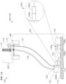
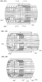
- Figures 1A and 1B depict schematic views of a sealed connector 132a,b usable in a communication (or fiber optic) system 122 at a wellsite 100. While Figure 1A shows an offshore wellsite 100, the sealed connector 132a,b may be used in a variety of applications, such as applications in any harsh or non-harsh environment. In this example, the wellsite 100 includes surface equipment 104 and subsea equipment 106. Also, while Figure 1 depicts the sealed connector 132a,b in use with a fiber optic termination 102 and fiber optic system 122, other terminations and/or communication systems may be used, such as electric terminations and systems.
- the surface equipment 104 includes a platform 108, a rig 110, and a surface unit 112.
- the rig 110 may optionally be placed on an offshore vessel, an onshore rig site, or other location.
- the surface unit 112 may be an operator's facility including a central processing unit (CPU) and associated electronics (e.g., database, power, communication, control, and/or other devices).
- the surface unit 112 may also include a source 114 usable with the fiber optic termination 102 for communication about the wellsite 100.
- the subsea equipment 106 includes a riser 118, sea floor equipment 120,126, and the fiber optic system 122.
- the fiber optic system 122 includes the fiber optic termination 102 and the sealed connector 132a.
- the riser 118 extends from the rig 110 to a wellbore 116 for passing fluid therebetween.
- the riser 118 may have conduits (e.g., choke and kill lines) and/or other equipment usable therewith.
- the sea floor equipment 120, 126 is positioned on the sea floor 115 about the wellbore 116 for performing wellsite operations.
- the sea floor equipment 120, 126 may include a variety of equipment, such as a blowout preventer, low riser marine package (LRMP), production tree, subsea distribution, and/or other devices used for performing wellsite operations.
- LRMP low riser marine package
- the fiber optic system 122 may include the source 114, one or more fiber optic cables 121, and/or one or more of the fiber optic terminations 102.
- the fiber optic system 122 may be coupled between the source 114 and the sea floor equipment 120 for communication therebetween.
- the fiber optic termination 102 may be positioned about (e.g., coupled to or positioned in) the surface unit 112 and/or the sea floor equipment 120 (e.g., near or away from the wellbore, e.g., at subsea distribution equipment).
- the fiber optic termination 102 may also be coupled to the source 114 and/or other surface equipment 104 by the fiber optic cable 121 for operation therewith.
- the fiber optic cable 121 may be connected between the source 114 and the fiber optic termination 102 and/or between the sea floor equipment 120 and the fiber optic termination 102 for passing signals therebetween.
- the source 114 may have a laser to pass light through the fiber optic cable 121 for measuring wellsite parameters.
- the CPU and/or electronics at the surface unit 112 may be used for sending signals (e.g., command, control, etc.) and/or receiving signals (e.g., measured data) from the fiber optic system 122 and/or the source 114.
- the fiber optic termination 102 may be a variety of devices capable of connecting the fiber optic cable 121 to the wellsite equipment for operation (e.g., communication) therewith.
- the fiber optic termination 102 may be a FIBERSAFE TM termination commercially available from ORMOND ENERGY INNOVATIONS INC. TM at www.oei2.com and www.thefibersafe.com. Examples of fiber optic communication systems and/or terminations that may be used are disclosed in in Patent/Application Nos.
- Communication couplings 124 may be provided about the wellsite 100 for passing data, power, control, and/or other signals therebetween. Communication couplings may be provided with on or offsite locations for operating the various equipment
- the fiber optic system 122 may be usable as one or more of the communication couplings 124 for communication about the wellsite.
- the fiber optic system 122 may be used to provide the communication coupling between the various equipment above the wellsite, such as the sea floor equipment 120 and/or the surface unit 112, for passing data therebetween.
- the fiber optic system 122 may be part of or separate from the communication couplings 124.
- the sea floor equipment 120, 126 may be connected by a communication coupling in the form of a fiber optic harness 134.
- the fiber optic system 122, communication couplings 124, and/or harness 134 may be used to provide the communication between the various equipment about the wellsite 100, such as the sea floor equipment 120, 126 and/or the surface unit 112, for passing data therebetween.
- the terminations 102 and/or sealed connectors 132a,b may be used to sealingly connect various portions of the wellsite, such as the communication couplings 124 and their respective equipment
- the sealed connector 132a,b may be provided for connecting various equipment (e.g., the sea floor equipment 120, 126) and/or portions of the fiber optic system 122.
- Each end of the fiber optic harness 134 may be connected to the sea floor equipment 120, 126 by a sealed connector 132a,b.
- the sealed connector 132a,b may also be coupled by a communication coupling 124 to the fiber optic termination 102.
- the sealed connector 132a,b may be used to removably connect equipment (e.g., sea floor equipment 120, 126), the termination 102, and/or other devices.
- the sealed connectors 132a,b each include a sealed plug 128a,b and a sealed receptacle 130a,b that are individually sealed, and jointly sealable when matably connected
- the sealed connectors 132a,b are intended to maintain a seal about the communication links, such as cables and/or fibers, passing therethrough while unmated, during mating, and after mating is completed as is described further herein.
- FIGS 1B-2B show various views of the sealed connectors 132a,b in use with the fiber optic termination 102 and/or the fiber optic system 122. As shown by these views, the sealed connectors 132a,b may be connected between portions of the fiber optic system 122 to provide a releasable connector that maintains a seal during connection and disconnection.
- the fiber optic system 122 includes the source 114 coupled by the cable 121 to the termination 102.
- the termination 102 is removably connected to equipment 126 by the sealed connectors 132a,b.
- the communication system 122 is depicted as a fiber optic system 122 with optical fibers 222 extending through the cable 121 and into the termination 102.
- the termination 102 in this example has a housing 328 and a fiber connection assembly 327.
- the fiber connection assembly 327 includes a storage base 334, a manifold 330, tube joints 323, and tubes 224, 324 to sealingly protect the optical fibers 222.
- the optical fibers 222 from the cable 121 extend into the housing 328, through the storage base 334, and through the manifold 330.
- the optical fibers 222 also pass through the cable tubes 224 and the termination tubes 324.
- Tube joints 323 are provided to seal about transitions between the tubes 224, 324 and/or components of the termination 102.
- the optical fibers 222 extend from the housing 328 in the termination tubes 324 for coupling to the sealed connector 132a.
- the termination 102 may provide a seal about the optical fibers 222 as described, for example, in WO2017161185 .
- the sealed plug 128a of the sealed connector 132a is connected to an end of the termination 102.
- the sealed receptacle 130a is connected to a first end of the harness 134.
- signals from the optical fibers 222 may pass from the source 114, through the termination 102, and to the harness 134 via the sealed connector 132a.
- At least a portion of the termination 102 and the sealed connector 132a may be supported by the seafloor equipment 120 ( Figure 2A ).
- the sealed receptacle 130b of the sealed connection 132b is connected to a second end of the harness 134.
- the sealed plug 128b is connected to the seafloor equipment 126.
- a portion of the housing 328d of the termination 102 may be positioned between the sealed plug 128a and the sealed receptacle 130b.
- the sealed plug 128a has a plug housing 416 sealingly connectable to the termination 102, and contacts 404 sealingly and operatively connectable to the tubes 324 by tube joints 323 with the optical fibers (e.g., 222 of Figure 1B ) therein.
- the receptacle 130a has a receptacle housing 716 and contacts 704 sealingly and operatively connectable to the tubes 324 and tube joints 323 of a harness connector 329.
- the harness connector 329 includes a connection housing 268 and flexible housing 270 that connects the sealed receptacle 130a to the harness 134 to pass the optical fibers therethrough.
- the contacts 404 of the sealed plug 128a and the contacts 704 of the sealed receptacle 130a are protectively sealed.
- FIGS. 1A - 2B show a sealed environment for passing the optical fibers 222 of the optical cable 121 from the source 114 to the various equipment 120, 126.
- the optical fibers 222 are protected within the sealed housing 328 and protective tubes 224, 324 as they pass through the termination 102.
- the optical fibers 222 may be sealingly connected to contacts 404 in the sealed plug 128a and contacts 704 of the sealed receptacle 130a, respectively.
- the sealed plug 128a,b and sealed receptacle 130a,b also maintain a seal about contacts 404,704 prior to and during connection to maintain fluid isolation about the optical fibers 222 and the contacts 404,704 as is described further herein.
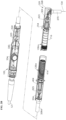
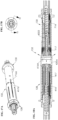
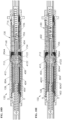
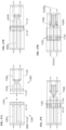
- FIGS 3A-3D show the sealed connector 132a in various positions including an unmated, engaged, triggered, and mated position, respectively.
- the sealed plug 128a and the sealed receptacle 130a each include the housing 416,716, the contacts 404,704, tine assemblies 406,706, push rod (trigger) 408,602, and bladders 411,711 as will be described further herein.
- a sealing operation of sealed connector 132a is introduced briefly here.
- the tine assemblies 406, 706 When unmated ( Figure 3A ), the tine assemblies 406, 706 are in an expanded position and the contacts 404, 704 are sealed within the housings 416, 716.
- push rods 408,602 engage with their respective mating tine rods 604, 302 in a sequence in conjunction with the bladder 411 engagement and movement of the bladder 711 to create a seal between the sealed plug 128a and the sealed receptacle 130a.
- the push rods 408, 602 push the respective mating tine assemblies 706, 406, which are shifted to a collapsed position in conjunction with the sealed bladder 411 moved by sealed bladder 711 to create a passageway 1702 therebetween ( Figure 3C ).
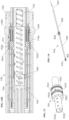
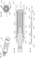
- FIGS 4A-4D show detailed views of the sealed plug 128 (which may be the sealed plug 128a and/or 128b).
- the sealed plug 128 includes the housing 416 and the internal assembly 417.
- the internal assembly 417 includes the plug support 402, the plug bladder assembly 410, the plug push rod 408, the plug contacts 404, and the plug tine assembly 406.
- An internal chamber 420a is defined within the housing 416.
- the internal assembly 417 is disposed in the internal chamber 420a of the plug housing 416, and is supported by the plug support 402.
- the housing 416 is a tubular member with an internal chamber 420a defined therein.
- the housing 416 has a connection end 4172 to sealingly receive the support 402, and a keyed end 4164 to receive the sealed receptacle 130.
- the keyed end 4164 has a bevel 4173 that tapers away from the connection end 4172 and has a keyway 4176 therein to receivingly engage the sealed receptacle 130.
- O-rings may be provided about the housing 416 to seal the support 402 with the housing 416.
- Locks 415 may be inserted through the housing 416 and into the support 402 to secure the support 402 to the housing 416.
- the housing 416 and the support 402 are shaped to receivingly connect to the termination 102.
- the housing 416 may sealingly engage the housing 328 of the termination 102 ( Figure 2B ).
- the housing 416 is a tubular member having a flange 4170 extending from an outer surface thereof.
- the flange 4170 is positioned adjacent to connection end 4172 to receivingly engage the housing 328 of the termination 102.
- a portion of the housing 416, such as the connection end 4172, may extend into the housing 328 of the termination 102.
- the housing 416 has a stepped inner surface with steps 4166, 4168, and 4178 defined therein.
- the steps 4168 and 4178 are shaped to receive the support 402.
- a bore 4162 is defined between the steps 4168, 4178 to engage the support 402.
- the step 4166 is shaped to act as a hard-stop to prevent over-travel of the sealed receptacle 130 as it enters the housing 416.
- the housing 416 also has longitudinal slots 4174 extending therethrough.
- the plug housing 416, support 402, and/or other portions of the sealed plug 128 may be a unitary or modular components made from materials capable of, for example, withstanding various operations, such as assembly, handling, installation and/or in-service loading (e.g., loading from the harsh environment, connector mating), corrosion resistance (e.g., to sea water), and/or compatibility with the operating environment and/or other components in physical and/or electrochemical contact with the sealed plug 128.
- assembly, handling, installation and/or in-service loading e.g., loading from the harsh environment, connector mating
- corrosion resistance e.g., to sea water
- compatibility with the operating environment and/or other components in physical and/or electrochemical contact with the sealed plug 128 e.g., assembly, handling, installation and/or in-service loading (e.g., loading from the harsh environment, connector mating), corrosion resistance (e.g., to sea water), and/or compatibility with the operating environment and/or other components in physical and/or electrochemical contact with the sealed
- the plug housing 416, support 402 may be made of a variety of materials, such as metallic (e.g., stainless steel, nickel, chromium, titanium, alloy (e.g., corrosion resistant metal alloys, super duplex stainless steel alloys, titanium alloys, nickel and chromium based alloys and/or austenitic stainless steel alloys, cathodic protected metals, etc.), etc.), non-metallic (e.g., polymer, plastic, nylon, ABS - Acrylonitrile Butadiene Styrene (ABS), PE - Poly Ethyelene (PE), PET - Poly Ethylene Terepthalate (PET), PBT - Poly Butylene Terepthalate (PBT), PTFE - Poly Tetra Fluoro Etyhyiene (PTFE), PEI - Poly Ether Imide (PEI), PEEK - Poly Ether Ketone (PEEK), etc.) and/or other materials and/or combinations thereof of various grades (e.g., rigid composite
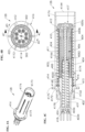
- Figure 5 shows a perspective view of the support 402.
- the support 402 includes a cylindrical portion 4021 having ends with smaller outer diameters extending from each end thereof.
- the outer diameters of the support 402 define a stepped outer surface shaped to extend into the housing 328 of the termination 102 at one end and into the housing 416 at the other end.
- the support 402 has an inner surface defining an inner chamber 419 and an internal shoulder 4036 ( Figure 4C ) therein.
- the cylindrical portion 4021 has shoulder 4027 shaped to seat along the step 4178 of the housing 416.
- the cylindrical portion 4021 also has holes 4023 extending therethrough to receive the locks 415 ( Figure 4C ).
- Grooves 4022 are positioned along an outer periphery of the cylindrical portion 4021 to receive the bladder 411 ( Figure 4C ) thereon.
- the support 402 has a bore 4030 therein, and bores 4026 positioned radially about the cylindrical portion 4021.
- a tapered inlet (or bevel) 4032 is positioned at an end of the bore 4030.
- the support 402 supports various components, such as the contacts 404, the bladder assembly 410, the push rod 408, and the tine assembly 406.
- An example contact 404 is shown in greater detail in Figure 6 .
- the contacts 404 include a ferrule 192, a front portion 194, a rear portion 196, and a middle portion 198.
- the ferrule 192 may have a tip matingly receivable by the contact 704 of the sealed receptacle 130 for communication therebetween as is described further herein.
- the ferrule 192 may be commercially available from THORLABS TM at www.thorlabs.com.
- Example contacts and/or ferrules are disclosed in US2017022807 .
- the ferrules used herein may be, for example, mechanical transfer (MT) ferrules usable with plural fibers and/or a cylindrical ferrule for hosting a single fiber.
- the MT Ferrule may replace a single fiber ferrule to provide multiple (e.g., 12) circuits.
- the geometry of the bladder assembly 410. the tine assembly 406, and the contacts 404 may be sized for use with the MT ferrule.
- the middle portion 198 has sealing grooves and a seating shoulder receivable in the support 402.
- the rear portion 196 may be sealingly connected to a communication link, such as optical fiber 222, for communication therewith.
- the rear portion 196 may also be coupled to a termination tube 324 disposed about the optical fiber 222 ( Fig. 2B ).
- the contacts 404 are linear members seated in the support 402 at the internal shoulder 4024.
- the bores 4026 are shaped and positioned to receive the contacts 404 therethrough. While the eight bores 4026 are depicted to correspond to eight contacts 404, various numbers of bores and contacts may be used.
- the contacts herein may be, for example, angle polish ferrule contacts and/or polish/ ultra polish ferrule contacts for use with a single fiber.
- the contacts may be used with a sealed plug 128 and/or sealed receptacle 130 with a corresponding angled orientation with matching angled ferrule face for mating. Examples of contacts that may be used are disclosed in US2017022807 .
- the contacts used herein may be made of a variety of materials, such as metallic, plastic, alloy, and/or other materials.
- the contact may be machined as single piece or joined from multiple pieces. Joining methods include bonding, laser beam welding, welding, ultrasonic welding, electron beam welding, brazing, soldering, casting by post processing machining, and/or other connection method and/or means. Coatings, corrosion protection, and/or other materials may be applied or integrated.
- the contacts 404 may be fixed to the support 402 by one or more retainers, such as discrete collars 1202.
- Each collar 1202 may be made out of a material, such as metal or plastic, capable of securing the contacts 404 in the support 402.
- the collar 1202 may be positioned to retain the contact 404 in place in the axial direction inside the bore 4026.
- the collar 1202 is a "C" shaped component having tapered ends.
- An inner surface of the collar 1202 is shaped to engage and retain the middle portion 198 of the contact 404.
- An outer surface of the collar 1202 is shaped to seat within the bore 4026.
- the collar 1202 may also be an internal retaining ring (not shown), such as a ring commercially available from SMALLEY STEEL RING CO. TM at www.smalley.com.
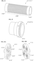
- the bladder assembly 410 includes a bladder 411, a disc 4112, and a seal plate 412.
- the bladder 411 has a tubular body with a chamber 420b defined therein.
- the tubular body has a support end 4102 with a bladder lip 4104 and a seal end 4106, with a ribbed middle portion 4108 therebetween.
- the bladder 411 may be made of a flexible material (e.g., elastomer) that may be stretched as needed, and/or metallic to endure extreme temperature applications.
- the middle portion 4108 may be in the form of bellows that compress and de-compress under axial movement or force with marginal change in outer and inner diameter.
- the seal end 4106 of the bladder 411 extends into the housing 416 towards the keyed end 4164 of the housing 416.
- the seal end 4106 (with or without the disc 4112) may be secured to the seal plate 412.
- the disc 4112 and the seal plate 412 may be circular members that are integrally formed with bladder 411, or secured together by bonding material (e.g., epoxy), or other means.
- the disc 4112 may be secured to the seal end 4106 of the bladder 411 or integrally formed therewith.
- the disc 4112 has sealing surfaces (or cylindrically shaped holes) 4116, 4118 therethrough and nipples 4120 positioned radially about a face of the disc 4112.
- the sealing surfaces 4116, 4118 extend through the disc 4112 and the sealing end of the bladder 411.
- the nipples 4120 are circular members extending through the disc 4112.
- a shaft sealing surface 4122 surrounded by a convex face seal 4114 is positioned about each of the nipples 4120.
- Face seal 4114 include an inner ring formed on the nipple and outer ring formed on the disc 4112.
- the face seals 4114 are shown as integrally molded in the plug bladder 411. In some cases, the face seal 4114 may be a separate seal that is bonded to the sealing face on the disc 4112 and the nipple 4120 of the plug bladder 411.
- Figures 9A-9C show various configurations of the face seals 4114a-c.
- the face seal 4114a-c may have various cross-sectional shapes, such as symmetric convex, outwardly shaped parabola and simple taper, respectively. Other shapes and configurations of seals may be used about the disc 4112 and/or seal plate 412.
- the seal plate 412 is positionable adjacent the disc 4112.
- the seal plate 412 has corresponding holes radially positioned for alignment with the nipples 4120 and face seals 4114.
- a central bore 4125 extends through the seal plate 412.
- Guide pins 422 extend radially from the seal plate 412 for engagement with the plug housing 416. The seal plate 412 seals with the seal end 4106 of the bladder and to disc 4112 to form a seal thereabout.
- the support end 4102 of the bladder 411 is supported between the housing 416 and the support 402.
- the support end 4102 of the bladder 411 stretches over a sealing shaft groove 4022 in the support 402.
- a retainer ring 414 is positioned in the support 402 about the support end 4102 to secure the bladder 411 about the support 402.
- the retainer ring 414 may be a tubular structure with collets 2102 extending from one end.
- the collets 2102 may spreads outwards when slid into position about the support 402 and bladder 411.
- the retainer ring 414 has an inner taper 2104 to receive the bladder 411.
- the retainer ring 414 may be made from material with memory (i.e., ductile materials) providing compliant action of the collets 2102.
- a spring 424 is disposed between the seal plate 412 and the step 4168 of the housing 416.
- the spring 424 may be used to bias the bladder 411 towards its base position near the connection end 4172 of the housing 416.
- the guide pins 422 are slidingly received within the longitudinal slot 4174 of the housing 416 as the bladder 411 and seal plate 412 move during operation.
- the longitudinal slot 4174 may act as a stop to define a travel distance of the bladder 411 and seal plate 412.
- the slot 4174 may be shaped to act as a hard-stop to prevent over-travel of the bladder 411 and seal plate 412.
- the support 402 has ports 4034 extending through an end thereof.
- the ports 4034 have access plugs 418 with an o-ring seal that may be removable for filling a chamber 419 defined in bore 4030 in support 402 and the chamber 420b in bladder 411 with a compressible fluid (e.g., oil, grease, gel, and/or other compatible fluid).
- the plug 418 may seal port 4034 and chambers 419 and 420b from ambient pressure. When the ambient pressure of the environment is experienced by the bladder 411, the bladder 411 may flex under the ambient pressure.
- the fluid in the chambers 419, 420b may compress until pressure in the chambers 419, 420b equalizes to the ambient pressure.
- the bladder 411 may be used to pressure balance the sealed plug 128 to the ambient environment. This pressure balancing may be performed without the sealed plug 128 being subject to differential pressure load.
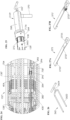
- the tine assembly 406 is supported in the support 402 and extends into the bladder 411.
- the tine assembly 406 includes a tine base 802, tines 804, and tine rods 302.
- the tine base 802 is a perforated, cylindrical member slidingly supported in the bore 4030 of the support 402.
- the perforations in the tine base 802 provide a path for the fluid to pass between the bore 4030 and the chamber 420b.
- a spring 426 is positioned in chamber 419 of the support 402 and extends into the tine base 802.
- the spring 426 seats against an end face 4036 of the support 402.
- the tine base 802 is slidably movable about the support 402 upon external force on the spring 426.
- the tines 804 and the tine rods 302 are connected at one end to the tine base 802.
- the tines 804 include linear arms 8046 extending from the tine base 802 and curved fingers 8044 positioned adjacent the seal plate 412.
- Tabs 8042 are positioned near the tine base 802.
- the tines 804 and the tine rods 302 may be movable with the base 802 in response to force on the spring 426.
- the tines 804 may be movable between an expanded position with the fingers 8044 spread apart ( Figure 11A ), and a collapsed position with the fingers 8044 closed together ( Figure 11B ).
- the fingers 8044 are positioned with the fingers 8044 in sealing contact with or adjacent the sealing surface 4122 and seal plate 412. In the expanded position, the fingers 8044 are positioned between the contacts 404 and the seal plate 412. In the expanded position, the tines 804 block the contacts 404 from passing through the seal plate 412.
- the fingers 8044 move together toward the push rod 408 located centrally therebetween.
- contacts 404 have clear passage through the seal plate 412 for connection with the sealed receptacle 130.
- the fingers 8044 move away from sealing surface 4122 and the bore 4125 in the seal plate 412 to allow the contacts 404 to pass through the seal plate 412 as the seal plate 412 is pushed toward the contacts 404 by the mating sealed receptacle 130 (see, e.g., Figure 3B ).
- the tines 804 collapse due to the tab 8042 engagement with the tapered inlet 4032 of the support 402.
- the tines 804 collapse and translate toward the end face 4036 of the support 402. Once force on the spring 426 is removed, the tines 804 return to the expanded position when the tab 8042 exits the bore 4030.
- the tine rods 302 are secured to the tine base 802 adjacent the tines 804.
- the tine rods 302 are linear members with ends positionable in sealing contact with or adjacent the sealing surface 4118 and seal plate 412. During operation, the tine rods 302 extend through sealing surface 4118. During expansion and collapse of the tines 804, the tine rods 302 translate linearly with movement of the tine base 802.
- Portions of the tine assembly 406, such as tines 804 may be unitary members or segmented as shown. While the arms 8046 are shown being linear and the fingers 8044 curved, part or all of the tines 804 may have a variety of shapes, such as linear, curved, cylindrical, rectangular cross-section, flat, and/or other shapes profiled for effective sealing. For example, the tines may have a flat rectangular cross-section with linear arms 8046 and outward bent fingers 8044 with or without curvature.
- the tine assembly 406 may be made of one or more materials to provide the desired movement during operation.
- the tine assembly 406 may be made of a variety of materials, such as metallic, plastic, and alloy materials.
- the material may be selected from material groups that exhibit memory resilience.
- Example material include spring steel, hastelloy, titanium-molybdenum alloy, live hinge plastic such as polypropylene.
- Resiliency may also be achieved by forming at least a portion of the tine assembly 406, such as portions of the aims 8046 near the tine base 802, as a helical spring or other compliant formed shape. Part or all of the tine assembly 406 may also have a coating.
- the tine assembly 406 may be integrally formed or modularly connected. Portions of the tine assembly 406 may be joined by bonding, laser beam welding, welding, ultrasonic welding, electron beam welding, brazing, soldering, and/or other connection method and/or means.
- the tine assembly 406 may be manufactured from casting, injection molding, fabrication process, and/or other means. For fabricated tine assembly 406, the tine base 802 may be machined, and the tines 804 may be bent to shape from machined rod.
- tine assembly 406 is depicted with a specific arrangement of a given number of tine rods 302 and tines 804, the arrangement and number may vary. Other actuators may be used to trigger the tine assembly 406, such as the push rod 408.
- the tine assembly 406 may employ flexing structures, and/or link mechanism with multi-segmented tines that collapse and retract with external actuation.
- a front face of the tine fingers 8044, push rods 408, and/or tine rods 302 may be used to affect precise timing of movement of relative mechanisms. This may be used to account for any spring lag.
- the push rod (trigger) 408 has an end supported in the support 402, and another end extending through the bladder assembly 410.
- the push rod 408 is positioned (e.g., centrally) between the tines 804.
- the push rod 408 may remain fixed as the seal plate 412 and the seal end 4106 of the bladder assembly 410 travels back and forth about the push rod 408.
- the push rod 408 has tabs 4082 extending radially therefrom for engagement with the tine base 802. The tabs 4082 limit travel of the tine base 802 towards the end 4164, and retains the tine base 802 about the bore 4030 of the support 402.
- the springs 424, 426 used in the sealed plug 128 may be compression springs to bias the bladder assembly 410 and tine assembly 406 between an unmated fully sealed position and a mated sealed position.
- a spring rate for springs 424 and 426 may be chosen to suit the connector mating mechanism, kinetics, sequence, etc.
- the spring lengths may be defined to provide a free length of the uncompressed spring with pre-load forces as needed to maintain the bladder assembly 410, seal plate 412, tines 804, and tine rods 302 in sealing engagement when the sealed plug 128 is in its unmated state.
- springs 424, 426 are shown as compression springs for providing the bias needed, one or more other types of springs, such as a disc spring, may be used.
- spring 426 may be replaced with a disc spring while spring 424 may be a compression spring.
- One or more springs may be used to achieve desired bias for a specific component.
- the springs 424, 426 may be made from variety of materials, such as metallic, plastic, and alloy. Coatings, corrosion/anti-fouling protection, and/or other materials may be applied to the spring.
- the sealed plug 128 may be assembled in various ways. For example, assembly may begin by pre-assembling the internal assembly 417. This pre-assembly may begin by coupling one or more contacts 404 to a fiber optic pig tail 222 of determined length. Each of the contacts 404 (with pig tail 222) may be passed through respective bores 4026 of the support 402 and seated therein by the collar 1202. Seals, such as o-ring type gland seals, may be used to seat the contacts 404 within the bores 4026.
- the tine assembly 406 may be pre-assembled with the tines 804, tine rods 302, and tabs 8042 connected to tine base 802. An end of the tine spring 426 may be inserted into the tine base 802. Initially, the spring 426 may be in an uncompressed state with the inserted tine assembly floating over it. The spring 426 and tine assembly 406 may then be positioned into the bore 4030 of the support 402. The tine assembly 406 may be adjusted to suit a desired orientation about the seal plate 412 and the bladder 411. Alignment and orientation features may optionally be added to the tines 804 and tine rods 302 to maintain the tine assembly 406 in a predefined orientation needed for assembly and connector operation.
- the push rod 408 is inserted through the tine base 802 and the array of tines 804.
- the tabs 4082 on the push rod 408 are pressed against the tine base 802 thereby compressing the tine spring 426.
- the push rod 408 may be pressed into position while aligning the tine base 802 within the bore 4030 of the support 402. After some movement and compression, an end of the push rod 408 may be fixedly threaded into the end face 4036 of the termination portion.
- the bladder 411 Before inserting the bladder assembly 410, the bladder 411 may be positioned inside out or stretched for installation. The end 4106 of the bladder 411 may be positioned adjacent ends of the tines 804, tine rods 302, and the push rod 408. The bladder 411 may slide over the tines, tine rods 302, and the push rod 408 as they are inserted into the bladder 411 until fully seated with disc 4112. Sealing may be established between tine fingers 8044 and the sealing surfaces 4122. Similarly sealing may also be established between the tine rods 302 and the push rod 408 with the sealing surfaces 4118, 4116, respectively.
- Pressure tight sealing may be affected by selecting diameters of the sealing surfaces 4122, 4118, 4116 that are smaller than a diameter of tine finger 8044, tine rod 302, and the push rod 408, respectively, thereby stretching the respective sealing surfaces over respective rods during seating.
- a seal/ bladder and the rod interface (or sealing interface) may be provided with a constant compressive load as a result of the stretch and constriction of the bladder 411 within the sealed plug 128.
- a magnitude of stretch that may be used may be based on a net differential pressure across the sealing interface, as well as other ambient conditions.
- the chambers within the sealed plug 128 may be in pressure equilibrium or pressure balanced with the ambient environment such that a net differential pressure across the sealing interface may be marginal.
- the diameters of the rods and sealing surfaces may be suitably chosen to achieve the required stretch and effective pressure seal for the specific ambient conditions.
- the bladder 411 With the bladder 411 positioned over the tine assembly 406, the bladder 411 may be seated on the sealing shaft groove 4022 of the support 402. The bladder 411 may be temporarily locked in place from the stretched seating over groove 4022 and by seating the bladder lip 4104 about the support 402.
- the retainer ring 414 is slid over the bladder 411 and secured to the support 402 about the bladder 411. During the sliding, the collets 2102 may spreads and ride over the outer diameter of the support 402, and the inner taper 2104 may compress the bladder 411 without unseating it. Further axial movement of the retainer ring 414 may continue to compressively engage the inner surface over the bladder 411 until the collets 2102 spring back into the grooves 4022 on the support 402.
- the housing 416 may be positioned about the internal assembly 417.
- the housing 416 may be preinstalled with the spring 424 compressed to its predetermined preload length and held in place by a removable temporary mounting fixture or other assembly aid.
- the pre-assembly may be aligned and oriented for insertion into the housing 416.
- the pre-assembly may be inserted into the housing 416 through end 4164.
- the pre-assembly may be held stationary while the housing 416 may be slid over the internal assembly 417.
- the support 402 of the internal assembly 417 begins to engage with the bore 4162 of the housing 416.
- the support 402 advances and seats at the step 4178 and seals with the seals along the bore 4162 to establish sealing engagement between the housing 416 and the support 402.
- Fasteners such as the locks 415 and the guide pins 422, may be used to secure the assembled sealed plug 128.
- the locks 415 may be inserted through the housing 416 and the support 402.
- the guide pins 422 may be attached to the seal plate 412 through the longitudinal slots 4174 of the plug housing.
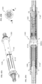
- the sealed receptacle 130 (which may be the same as sealed receptacle 130a,b) is shown in greater detail in Figures 12A-12D .
- the sealed receptacle 130 is similar to the sealed plug 128 with some variations to allow for mating and operation with the sealed plug 128.
- the sealed receptacle 130 includes the housing 716 and the internal assembly 717.
- the internal assembly 717 includes the receptacle support 702, the contacts 704, the bladder assembly 710, a push rod (trigger) 602, and the tine assembly 706.
- the components of the sealed receptacle 130 correspond to the components of the sealed plug 128 for sealed connection and operation therewith.
- the components of the sealed receptacle 130 may be made from the same materials as the corresponding components of the sealed plug 128.
- the housing 716 and the internal assembly 717 are similar to the housing 416 and internal assembly 417 of the sealed plug 128.
- the sealed receptacle 130 is shaped for connection to the harness 134 at one end and the sealed plug 128 at another end.
- the housing 716 is similar to the housing 416, except that the housing 716 has a seal end 7164 receivable by the sealed plug 128, and a connection end 7172 connectable to equipment (e.g., harness 134). Also, the housing 716 has a short slot 7175 and holes 7176 therethrough. The holes 7176 may be provided for supporting a connector retention mechanism as is described further herein.
- the housing 716 is a tubular member with a flange 7170 extending from an outer surface of the housing 716.
- the flange 7170 is positioned adjacent connection end 7172, and has holes 7174 to receivingly engage the harness 134.
- the flange 7170 and a connection end (rear shaft) 7172 may be shaped for interface fit with the harness 134 onto which the sealed receptacle 130 is to be mounted.
- a chamber 720a is defined within the housing 716.
- the receptacle housing 716 and/or its portions may be a unitary or modular component made from similar materials with or without coatings.
- connection end 7172 sealingly receives the support 702 into the chamber 720a.
- the housing 716 has a stepped inner surface with steps 7168, and 7178 defined therein.
- the step 7178 is shaped to receive the support 702.
- the receptacle 130 may be provided with o-rings about the housing 716 to seal the support 702 with the housing 716.
- Locks 715 may be inserted through the housing 716 and into the support 702 to secure the support 702 to the housing 716.
- the sealed receptacle 130 is also provided with a key 7166 matingly receivable in the keyway 4176 of the sealed plug 128.
- the orientation key 7166 is connected to (e.g., by interference fit, threads, etc.) or integral with the housing 716.
- the orientation key 7166 may be positioned about the seal end 7164 for receipt in keyway 4176 of the sealed plug 128.
- the orientation key 7166 may be used to define an aligned position for connection of the sealed plug 128 and the sealed receptacle 130 during mating.
- Figure 13 shows a perspective view of the support 702.
- the support 702 includes a cylindrical member 7021 having smaller diameter ends extending from each end thereof, a bore 7030 therein, a taper (chamfer) 7032 at an entry end, a stepped outer surface defining a shoulder 7027 shaped to engage the step 7178, holes 7023 to receive the locks 715, grooves 7022 to receive the bladder 711 thereon, and bores 7026 to receive the contacts 704.
- the support 702 supports various components in the housing 716, such as the contacts 704, the bladder 720, the push rods 602, and the tine assembly 706.
- An example contact 704 is shown in greater detail in Figure 14 .
- the contacts 704 include a ferrule 202, a female sleeve 210, a front portion 204, a rear portion 206, and a middle portion 208.
- the ferrule sleeve 210 may have a slot to matingly receive the ferrule 192 of the contact 404 in the sealed plug 128 for communication therebetween.
- the middle portion 208 has sealing grooves and a seating shoulder receivable in the support 702.
- the rear portion 206 may be sealingly connected to a communication link, such as optical fiber 222, for communication therewith.
- the contacts 704 may be linear members made of similar materials using similar techniques.
- the bores 7026 in the support 702 are shaped and positioned to receive the contacts 704 therethrough.
- the contacts 704 are seated in the receptacle support 702 at shoulder 7024.
- the contacts 704 may be fixed to the sealed receptacle 130 by one or more retainers, such as the collar 1202 ( Figure 7 ).
- a contact spring 1404 may be provided about the collars 1202 to allow biasing of contacts 704 when in mating engagement with contact 404. The contact spring 1404 allowing the contact 404 to move, thereby making the contact spring 1404 compliant.
- the bladder assembly 710 includes a bladder 711, the disc 7112, and the seal plate 712 similar to the corresponding items in the sealed plug 128.
- the bladder 711 has a support end 7102 with a bladder lip 7104 and a seal end 7106, with a ribbed middle portion 7108 therebetween.
- a central bore 7125 extends through the seal plate 712.
- the disc 7112 has sealing surfaces (or cylindrically shaped holes) 7116, 7118, nipples 7120, and face seals 7114 and sealing surfaces 7122.
- the sealing surfaces 7116, 7118 extend through the disc 7112 and the sealing end of the bladder 711.
- the bladder 711 has a chamber 720b defined therein. Like chamber 420b, the chamber 720b may be filled with fluid through port 7034 with plugs 718 and pressure balanced.
- the middle portion 7108 of the bladder 711 has rib sections 7109, 7110.
- the rib section 7109 may be in the form of bellows that compress and de-compress under axial movement or force with marginal change in outer and inner diameter.
- the rib section 7110 is a straight tubular section with longitudinally spaced circular beads 7111 for structural support.
- the bladder 711 is secured at one end in between the housing 716 and the support 702 by the retainer ring 414 ( Figure 8 ) and at the other end by seal plate 712.
- the bladder lip 7104 is seated over groove 7022 and secured by the retainer ring 414.
- the seal plate 712 may have guide pins 722 that are slidingly received within the short slot 7175 of the housing 716 as the bladder 711 and a seal plate 712 move during operation.
- a spring 724 is positioned around bladder 711 between the seal plate 712 and the step 7168.
- the step 7168 is shaped to act as a hard-stop in conjunction with compressed spring 724 to prevent over-travel of bladder assembly 710 during triggering of tine assembly 706 by the plug push rod 408.
- the spring 724 is positioned between the seal end 7164 and the contacts 704.
- the spring 724 is also positioned about the rib section 7109 of the bladder 711, thereby providing limited travel for the rib section 7109 and seal plate 712 therebetween.
- the spring 724 may extend partially around the rib section 7110 of the bladder 711., thereby allowing the rib section 7110 to remain stationary.
- the tine assembly 706 is similar to the tine assembly 406.
- the tine assembly includes a tine base 902, tines 904, and tine rod 604.
- the tines 904 have arms 9046 with fingers 9044 that move between the expanded position to block the contacts 704 and the collapsed position unblocking the contacts 704 from coupling with the mated plug contacts 404.
- the tine fingers 9044 are in sealing contact with or adjacent the sealing surface 7122 and the seal plate 712.
- the tines 904 are similar to the tines 804, except that the tine fingers 9044 may be longer than the tine fingers 8044 to provide sequential triggering of the tines 804 and the tines 904.
- the tines 904 move between the expanded position (16A) and collapsed position (16B) by deflection about tabs 9042.
- the fingers 9044 are positioned radially about a single, linear central tine rod 604 and extend a distance beyond the tine rod 604 for engagement with the sealing surface 7122 and seal plate 712.
- the tine rod 604 is a distance behind the fingers 9044 and sealingly passes through sealing surface 7116 as it passes thereby.
- Tine spring 726 is positioned in a chamber 719 in the support 702 about the push rods 602. Tine spring 726 extends between the tine base 902 and end face 7036 of the support 702. The spring 726 is seated at the end face 7036 and compresses as the tine assembly 706 moves with the plug push rod 408.
- the springs 724, 726 may be made of similar materials and be of a similar type as the springs 424, 426.
- the push rods 602 are supported at one end by the support 702 and are positioned about the tine spring 726.
- the push rods 602 pass through holes 906 on the tine base 902 to support the tine assembly 706 about the support 702.
- an opposite end of the push rods 602 are positioned adjacent the fingers 9044 and extend a distance beyond the tine rods 604 for engagement with sealing surfaces 7118 and seal plate 712.
- the push rods 602 remain fixed as the seal plate 712 and the seal end 7106 of the bladder 711 travel back and forth about the push rods 602.
- the push rod 602 has tabs 6022 extending radially therefrom for engagement with the tine base 902 (see Figure 18A ). The tabs 6022 limit travel of the tine base 902 towards the end 7164, and retain the tine base 902 about the bore 7030 of the receptacle support 702.
- the sealed receptacle 130 may be assembled in a similar manner as the sealed plug.
- the internal assembly 717 of the sealed receptacle 130 may be pre-assembled by connecting the contacts 704, fiber optic pig tail 222, collar 1202, retaining ring 414, tine assembly (and/or pre-assembly) 706, tine spring 726, receptacle support 702, and bladder 711 that is already in sealing engagement with seal plate 712.
- the bladder 711 is disposed over the tines 804 and rods 602, 604, and sealing is established between the tine fingers 9044 and rods 602, 604 with their respective sealing surfaces 7122, 7118, and 7116.
- the bladder 711 is unrolled and seated on the groove 7022 of the receptacle support 702, and locked in place while retainer ring 414 installed over bladder 711 and the termination portion to complete the pre-assembly.
- the spring 724, housing 716 may then be secured about the internal assembly 717, and sealed with the support 702.
- the locks 715 and guide pin 722 secure the components in place.
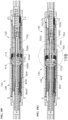
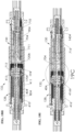
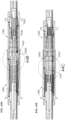
- FIGS 17A-19C shows various views of the sealed connector 132, the sealed plug 128, and the sealed receptacle 130 in various stages of connection. As shown in these views, the receptacle 130 is seatable in the sealed plug 128. Various equipment, such as the termination 102, the harness 134, the sea floor equipment, or other equipment may be connected to the sealed plug 128 and/or the sealed receptacle 130 before or after mating.
- the sealed plug 128 and the sealed receptacle 130 may be positioned in gross alignment for mating.
- the keyway 4176 of the sealed plug 128 may be aligned with key 7166 of the sealed receptacle 130 for sliding engagement therebetween.
- the receptacle 130 is moved forward, the receptacle 130 is guided by the keyway 4176 to begin mating with the plug 128.
- the mating may be performed according to the sequence demonstrated by Figures 18A-18I .
- the sealed plug 128 or the sealed receptacle 130 may be stationary as they are drawn together for mating. Due to the pressure balancing and spring forces of the components of the sealed connector 132, the sealed connector 132 may be triggered to create a seal between the sealed plug 128 and the sealed receptacle 130.
- the sealed plug 128 is positioned to receive the sealed receptacle 130 through end 4164 and into chamber 420a of the housing 416.
- the housings 416, 716 may engage as shown in Figure 18A to prepare the internal assemblies 417,717 to engage.
- the internal assemblies 417,717 are at a distance from each other during the disconnected stage.
- the sealed receptacle 130 has entered the sealed plug 128 and advanced such that its disc 7112 is about to make contact with the disc 4112 of the sealed plug 128.
- the push rods 602 of the sealed receptacle 130 makes positive contact with the tine rods 302 of the sealed plug 128, and the tine fingers 9044 are in latent contact with tine fingers 8044.
- the receptacle tine fingers 9044 continue to be in non-pressure contact with plug tine fingers 8044 and simply follow the plug tine fingers 8044 in translation due to the forward mating movement of the sealed receptacle 130. In other words, the relative position of the receptacle tine 904 to the push rods 602 within the sealed receptacle 130 remains the same.
- the receptacle tine 904 may not depress within the sealed receptacle 130 as positive contact is not yet established between the receptacle tine rod 604 and the plug push rod 408.
- the receptacle seal plate 712 is also not depressed as positive contact is not established with the plug seal plate 412 through the disc 7112,4112 respectively.
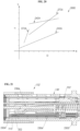
- Figure 20 is a graph depicting relative spring force (F) (y-axis) versus relative distance traveled (D) (x-axis).
- the lines 2424, 2426, 2724, 2726 correspond to the springs 424, 426 and 724, 726 of the sealed plug 128 and the sealed receptacle 130, respectively, (the "connector springs").
- Line 2424 refers to the plug spring 424 spring constant profile.
- Line 2426 refers to the plug tine spring 426 spring constant profile.
- Line 2724 refers to the receptacle spring 724 spring constant profile.
- Line 2726 refers to the receptacle tine spring constant profile.
- the spring forces may be manipulated as set forth in Figure 20 as is described with the mating sequence 18A-18I.
- graph 2000 the components under spring bias in the sealed plug 128 and the sealed receptacle 130 are under different preload forces with a relative magnitude as demonstrated by Figure 20 .
- advancement of the sealed receptacle 130 towards the sealed plug 128 (mating stroke) of Figure 18B depresses the plug tine assembly 406 without depressing the other components under spring bias.
- the magnitude of preload force of the plug spring 424 is greater than the combined spring force of the plug tine spring 426 and the receptacle spring 724. Further forward movement of the sealed receptacle 130 needs to overcome the receptacle spring preload force 724 and the plug tine spring force 426. As the mating stroke continues, the receptacle seal plate 712 is depressed while the plug tine assembly 406 continues to depress further under the overcoming of spring forces from the mating. The receptacle seal plate 712 moves within the sealed receptacle 130 guided by the guide pin 722 that travels along the short slot 7175 in the housing 716. With this guided movement, the rib section 7109 of the receptacle bladder 711 compresses evenly while maintaining its shape.
- the disc 7112 and disc 4112 are brought closer to each other with a marginal gap therebetween.
- physical contact is established between the convex face seal 4114 on the plug nipples 4120 ( Figure 8 ) and the concave face seal 7114 on the receptacle nipples 7120 ( Figure 15 ).
- seawater around the face seals 4114, 7114 between the disc 4112 and the disc 7112 is pushed outwardly away from the axis of the face seals 4114, 7114.
- the convex face seal 4114 on the disc 4112 and the concave face seal 7114 on the disc 7112 begin to engage and make physical contact as the seawater pushes out until interface therebetween is benign and the seawater is expunged away.
- the convex face seals 4114 and concave face seals 7114 compress together to form a pressure tight sealing interface.
- a magnitude of compression of this interface is relational to the mating force generated from overcoming the spring forces of respective sealed plug and receptacle 128, 130.
- the face seal compression may result from force of the receptacle spring 724.
- the face seal compression may continue and include force of the plug spring 424.
- Pressure balance to the ambient environment within the sealed connector 132 results in a marginal net differential pressure across the face seals 4114, 7114 irrespective of a direction in which it presents. Accordingly, the compression required for the face seals 4114, 7114 to affect a pressure tight seal may be minimal, and an amount of the compression needed from connector mating may be assumed to be adequate for a pressure tight seal, even in a harsher environment
- the force generated has not reached the threshold to overcome the plug spring 424 preload force.
- the receptacle seal plate 712 and plug tine assembly 406 continue to depress in their respective portions of the connector 132.
- the receptacle tines 904 may continue to move forward in translation while being in latent contact with the plug tines 804.
- the plug push rod 408 and the receptacle tine rod 604 are brought to engagement to establish physical contact.
- the plug push rod 408 is fixed and stationary within the sealed plug 128, while the engaging receptacle tine rod 604 is under spring bias from tine spring 726.
- the receptacle tine spring 726 preload force is overcome, the receptacle tine assembly 706 depresses within the sealed receptacle 130.
- the plug tines 804 are disengaged from the plug seal plate 412.
- the plug tine fingers 8044 are no longer in shaft sealing engagement with the plug sealing surfaces 4122.
- the receptacle tine fingers 9044 are in sealing engagement with both the plug sealing surfaces 4122 and receptacle sealing surfaces 7122.
- the receptacle seal plate 712 is fully depressed within the sealed receptacle 130.
- any forward movement of the sealed receptacle 130 brings translation movement of the receptacle seal plate 712 since the compressed spring 724 is bottomed against the step 7168 in the receptacle housing 716. Further mating stroke movement builds up resistance that overcomes the preload spring force of plug spring 424, the preload spring force of the tine spring 726, the spring force of the tine spring 426. and frictional resistance. As a result, continued mating of the sealed plug and receptacle 128, 130, depresses both the plug tine assembly 406 and the receptacle tine assembly 706.
- the plug seal plate 412 is depressed within the sealed plug 128 while in sealing engagement with the stationary receptacle seal plate 712 through the disc 4112, the disc 7112, and the face seals 4114, 7114 (see, e.g., Figure 19A ).
- receptacle tine assembly 706 depresses within the sealed receptacle 130 with the tine fingers 9044 separating away from the plug tine fingers 8044. Concurrently, the plug tine assembly 406 continues to depress within the sealed plug 128. As a result of this, plug bladder sealing surfaces 4122 is in non-engagement with the tine fingers 8044. But a portion of the sealing surfaces 4122 is still in sealing engagement with the receptacle tine fingers 9044. As the mating progresses, the plug tine assembly 406 move within the sealed plug 128 to bring the plug tine tabs 8042 ( Figure 11A ) in engagement with support 402. These tabs 8042 initially engage with the tapered inlet 4032 of the support 402. Due to frictional reaction, the tines 804 collapse by deflecting inwardly.
- the tines 804 and the tabs 8042 enter the bore 4030.
- the tine assembly 706 depresses further and disengages from the receptacle seal plate 712.
- the receptacle tine fingers 9044 are no longer in shaft sealing arrangement with the bladder sealing surfaces 7122 ( Figure 15 ).
- sealed passageways 1702 is created between the plug chamber 420b and the receptacle chamber 720b.
- the passageways 1702 connects the fluid volume of both the plug and receptacle chambers 420b, 720b.
- the receptacle tine assembly 706 within the sealed receptacle 130 brings the tine tabs 9042 in engagement with the support 702.
- the tabs 9042 initially engage with the taper 7032 along the bore 7030. Due to frictional reaction, the tines 904 collapse by deflecting inwardly. With continued mating, the tines 904 and the tabs 9042 enter the bore 7030.
- the plug tines 804 and the receptacle tines 904 are in collapsed position, and the passageways 1702 clears for connection of the plug contacts 404 and the receptacle contacts 704.
- the annulus 1704 volume may be based on sizing of the plug contact 404 front portion 194 relative to a diameter of the sealing surfaces 4122 and 7122.
- the sizing of the shaft sealing surfaces diameter may be suited to enable unobstructed passage of the plug contact 404 and effective pressure sealing of the respective chambers 420b, 720b in unmated and mated state.
- the plug contact 404 may be in sealing contact with one or both the sealing surfaces 4122, 7122.
- the plug front portion 194, the sealing surfaces 4122, 7122, and the respective tines 804, 904 may be suitably sized to achieve pressure sealing of the chambers 420b, 720b in the respective sealed plug and receptacle 128, 130 in both an unmated and a mated state.
- pressure sealing of respective chambers 420b, 720b may be maintained by the penetrating plug contact 404.
- the receptacle contacts 704 are brought closer to the plug contacts 404.
- the contacts 404, 704 are radially and angularly aligned for contact therebetween.
- the ferrule 192 of the plug contact 404 makes initial contact with the sleeve 210 of the receptacle contact 704.
- the plug ferrule 192 is finely aligned with the receptacle ferrule 202. During this alignment action both the contacts 404, 704 may flex to accommodate the alignment reaction forces.
- the ferrule 192 of the plug contact 404 and the fenule 202 of the receptacle contact 704 are brought in contact with each other. As this contact mating continues, the plug contact 404 pushes the receptacle contact 704 and overcomes the preload spring force of the contact spring 1404. At this stage, further mating or over-travel may not occur as the step 4166 of the plug housing 416 provides hard-stop to the housing 716 of the mating sealed receptacle 130. The plug 128 and receptacle 130 are now considered fully mated.
- the contacts 404 and 704 are aligned in radial and angular directions, physically mated with constant spring force from the contact spring 1404 and maintaining the physical contact between ferrules to provide communication between the sealed plug and receptacle 128, 130.
- the mated contacts 404, 704 are maintained in a benign environment of the chambers 420b, 720b with pressure tight sealing maintained between chambers and the ambient environment.
- Figures 21-28D show example variations that may be provided in the sealed connector 132.
- Figure 21 shows a modified seal connector 132' with a dual sealed receptacle 130'.
- the sealed connector 132' may be similar to the seal connector 132, except that an additional discrete bladder 2306 may be mounted within the sealed plug 128' and/or the sealed receptacle 130'.
- the bladder 2306 may be made out of the same material and filled with similar fluids as the bladder 711.
- the bladder 2306 is a tubular structure with a sealing end, a tapered rear end, and a stepped inner diameter.
- the bladder 2306 may be mounted onto support 702' in the receptacle 130' (and in a similar position in a corresponding plug).
- a seal end of the bladder 2306 may be filled with an immobile, viscous gel 2304, such as a soft cure optical index matching gel.
- Part or all of the bladder 2306 may be filled entirely with gel 2304.
- the gel may be immobile (e.g., retained in place within the sealing end of the bladder 2306), and also pliable under external force.
- the plug contact 404 with the ferrule 192 enters the bladder 2306 ( Figures 18A-I ), and the ferrule 192 pierce through the gel 2304 before entering the ferrule sleeve 210 of the mated ferrule 202 of contact 704.
- a retaining ring 2302 may be used in place of the collars 1202 (which may be discrete to respective contacts).
- the retaining ring 2302 may held in place by fasteners connected to the support 702'.
- FIGs 22A and 22B show a modified sealed plug 128' with the tines 804 in an expanded and collapsed position, respectively.
- the modified sealed plug 128' includes an additional tine return assist mechanism 240 mounted about the seal plate 412' and push rod 408.
- Figures 23A and 23B show the tine return assist mechanism 240 in greater detail.
- the tine return assist mechanism 240 may be a spring mechanism including a base body 2404 and biased plungers 2402 that detent and return upon application of load and removal.
- the tine fingers 8044 of the tine 804 is in proximity to the plunger 2402.
- a radial compressive load overcomes a plunger bias thereby compressing the plunger 2402.
- a spring force of the plungers 2402 ensure positive return of the tines 804 to a fully expanded state prior to the tine fingers 8044 entering the sealing surface 4122 in the bladder 411'.
- Figure 24 shows another mated connector 132" in an electric/optical configuration.
- the mated connector 132" is similar to the mated connector 132, except that electric contacts 430 and 730 are also included.
- the electric contact 730 of the sealed receptacle 130" includes an insulator 292 and a conductor 294 with an internal shaft.
- the electric contact 430 of the sealed plug 128" includes an insulator 282, a conductor 284. When fully mated the plug conductor 284 is fully inserted into the receptacle conductor 294 with the electric contact element 296 making positive contact with the plug conductor 284.
- the conductor 294 has a forward portion with a socket that houses the contact element 296 and a rear portion with a tubular shaft to receive an electric wire from the termination or other equipment.
- the conductor 284 has a forward portion with a spherical tip and a rear portion with a tubular shaft to receive the electric wire from termination or other equipment.
- the insulator 292, 282 may be a machined or injection molded component that is assembled with bonding onto or molded over the conductor 294, 284 respectively.
- the conductor 294, 284 may be a machined component that is made from electrically conductive material such as copper, aluminum, bronze etc., Insulator may be made from electrically insulative material such as LDPE, MDPE, HDPE, PEI, PEEK etc.
- the electric contacts 430, 730 are tubular structures similar to the contacts 404, 704, with sealing grooves and a seating shoulder at a middle portion thereof.
- the contact 730 have a contact element 296 that makes positive contact with 430 and conducts electricity through wire to termination or other equipment.
- the contact element 296 may be a stamped thin cross section made of electrically conductive material formed into a cylindrical shape that stretches when mated with a pin.
- the contact element 296 may be contact bands commercially available electric component, for example from MOUSER ELECTRONICS TM at www.mouser.com.
- FIG 25 shows a retention mechanism 2129 usable for connecting the mated connector 132.
- the retention mechanism 2129 may be used to connect the sealed receptacle 130 to the sealed plug 128.
- the retention mechanism 2129 may be supported by an ROV (remote operated vehicle - not shown) while carrying the sealed receptacle 130 for connection.
- the sealed plug and receptacle 128, 130 may be mated by using the ROV to lift the sealed receptacle 130 into position to mate with the sealed plug 128.
- the retention mechanism 2129 includes the housing 268 and the flexible housing 270.
- the termination housing 268 has an inlet to receive the sealed receptacle 130 therein, and may be provided with termination tubes 324 and tube joints 323 for connection to the contacts 704 of the sealed receptacle 130 as shown in Figures 2A and 2B .
- the optical fiber pigtail 222 from the contact 704 is protectively housed within termination tubes 324 and contained within the housing 268 and the flexible housing 270.
- the retention mechanism 2129 may also include a handle 262, lock plates 272 and a handle retainer 264 for use during connection.
- the handle 262 is movably mounted to the sealed receptacle 130, through holes 7174 on the receptacle housing 716.
- the handle 262 may be shaped for grabbing by the ROV during installation.
- the handle 262 may be held in place about the retention mechanism 2129 by handle retainer 264.
- the handle retainer 264 is a cylindrical member positioned about the inlet of the retention mechanism 2129.
- the handle 262 is a tuning fork shaped structural member with a fork portion 2622 and a handle portion 2624.
- the handle portion 2624 is shown as being T-shaped, and could have other shapes and/or employ other industry standard ROV handle interfaces.
- the handle portion may have a fish tail or D handle shape.
- One or more locking plates 272 may be mounted to the housing 716 with fasteners.
- four locking plates 272 at equally spaced angle around the sealed receptacle 130 is shown.
- Other shapes, orientations and fastener locations may be used.
- FIGS 27A-27B shows example lock plates 272, 272', respectively.
- the locking plate 272 includes a front tip 2722 and a rear block 2725 connected by rib portion 2727.
- the front tip 2722 is receivable in a cut out 2602 in the plug housing 416.
- the rib portion 2727' may be modified to include a serrated rib spring or bellow type arrangement.
- the spring/bellows may be used to facilitate compliance of the lock plate 272' to the sealed receptacle 130 and/or to minimize frictional forces during connection and/or disconnection thereon.
- Part or all of the retention mechanism 2129 may be made out of corrosion resistant metallic material, coated metallic material or other rigid thermoplastics suitable for the loading requirements of the connector mass and mating spring forces. Part or all of the retention mechanism 2129 may also be manufactured from casting, molding, and fabrication with welding or other suitable manufacturing processes, and/or manufactured from machining or cast and finish machined.
- FIGs 28A-28D show mating of the retention mechanism 2129.
- the front tip 2722 of the lock plate 272 is positioned to engage with the entry taper 2710 of the plug housing 416.
- the inner face 2642 of the handle retainer 264 is pushed against the lock plate rear block 2725.
- forward movement of the receptacle 130 by the ROV engages the lock plate 272 with the housing 416 as shown in Figure 28B .
- the cantilevered lock plate 272 conforms and deflects from the frictional interaction of the taper surfaces.
- the lock plate front tip 2722 tracks the inner diameter profile of the sealed plug 128 until it is clear of circumferential restriction thereof.
- the front tip 2722 of the lock plate 272 clears circumferential restriction when the mating stroke brings it to the cut out 2602 on the seal portion of the sealed plug 128. In the absence of restriction and associated frictional forces, the lock plate 272 returns back to its natural state which results in the front tip 2722 of the lock plate 272 locks in place inside the cut out 2602. At this point, the connector contacts 404,704 ( Figure 24 ) are fully mated.
- the ROV may then relieve the handle 262 and depart.
- the lock plate 272 mounted on the cut out 2602 of the sealed plug 128 is sufficiently load bearing member to keep the sealed plug 128 and the sealed receptacle 130 mated against the axial forces of the connector springs therein.
- the ROV may grab the handle 262 and gradually pull the handle 262. As a result of this action, the retainer 264 of the handle 262 is pulled backwards. The tapered surface 2644 of the retainer may be brought in contact with the lock plate 272 as shown in Figure 28D . Continuous pulling of the handle 262 by the ROV results in increased frictional force between the retainer 264 and the lock plate 272.
- the cantilevered lock plate 272 deflects and the front tip 2722 unlocks from the cut out 2602. Now the axial forces from the connector springs are balanced by the ROV grab of the handle 262. Gradual pulling of the handle 262 causes the lock plate 272 to track along an inner diameter of the sealed plug 128. Further backward movement brings the lock plate 272 out of the sealed plug 128. Continued movement fully demates the sealed receptacle 130 from the sealed plug 128.
- Figures 29 and 30 show a modular version of the sealed plug 128′′′ and sealed receptacle 130′′′.
- the sealed plug 128′′′ and the sealed receptacle 130′′′ may have features similar to the sealed plug 128 and sealed receptacle 130, which have been simplified for circuit density, modularity, ease of component manufacturing, assembly, and cost-efficient mass production.
- the sealed plug 128′′′ includes a modular housing 416′′′ and an internal assembly 417′′′.
- the modular housing 416′′′ includes a tip 4164′′′, a base 4716′′′, and a tube 4173′′′.
- the tip 4164′′′ is shaped for engagement with the receptacle 130"'.
- the base 4716′′′ is shaped for engagement with the equipment (e.g. 120 of Figure 1A ), and to receive the support 402′′′.
- the tube 4173′′′ has the tip 4164′′′ connected at one end and the base 4716′′′ on an opposite end thereof.
- the internal assembly 417′′′ includes a support 402′′′ a bladder assembly 410′′′, a tine assembly 406′′′, and contacts 404′′′.
- the support 402′′′ is similar to the support 402 of Figure 4C , except that it has been modified to include features of the support 702 of Figure 12C .
- the support 402′′′ is secured in the housing base 4716′′′ and has a connection end that extends therefrom for connection with optical fibers 222.
- a bladder end of the support 402′′′ extends into the bladder assembly 410′′′ and is slidably movable through the tube 4173′′′.
- the tine assembly 406′′′ and contacts 404′′′ are supported in the support 402′′′ and extend into the bladder assembly 410′′′.
- Guide rods 4718 extend from the connection end of the support 402′′′ to the tine assembly 406′′′ for providing support and guidance thereto.
- the receptacle 130′′′ may be similar to the plug 128′′′, with corresponding parts configured to seal with the mated plug 128′′′.
- the receptacle 130′′′ includes a modular housing 716"' and an internal assembly 717′′′ for matably sealing with the corresponding housing 416′′′ and internal assembly 417′′′ of the plug 128′′′.
- the modular housing 716′′′ includes a tip 7164′′′ corresponding to the plug tip 4164"', a tube 7173′′′, and the same base 4716′′′.
- the internal assembly 717′′′ is similar to the internal assembly 417′′′ and includes the same support 402′′′.
- the internal assembly 717′′′ also includes a bladder assembly 710′′′, a tine assembly 706′′′, contacts 704′′′, and guide rods 7718.
- Figures 31-35 show detailed views of components of the sealed plug 128′′′ and/or sealed receptacle 130′′′.
- Features of the plug 128′′′ may be similar to the sealed plug 128 with some variations for simplification.
- FIGS 31-33B show portions of the bladder assembly 410′′′ and 710′′′ in greater detail.
- the bladder assembly 410′′′ is similar to the bladder assembly 410 of Figure 8 , except that the sealed bladder 410′′′ has been simplified to include a bladder 411′′′ , seal plate 4712, and a seal end 4115.
- the bladder assembly 710′′′ is similar to the bladder assembly 710 of Figure 16 , except that the sealed bladder 710′′′ has been simplified to include a bladder 711′′′ , seal plate 7712, and a seal end 7115. As shown in these views, the bladder assembly 410′′′ may have various configurations to facilitate operation and/or manufacturing.
- the bladder 411′′′ is similar to the bladder 411 of Figure 8 , except that the bladder 411′′′ is symmetric.
- the bladder 411′′′ includes a ribbed middle portion 4108′′′ with symmetric support ends 4102′′′ on either side thereof (and without the bladder lip 4104).
- the support ends 4102′′′ are standardized to interface with support 402′′′ ( Figure 29 ) and seal plate 4712 to facilitate assembly of the bladder 411′′′ at any orientation.
- the support end 4102′′′ of the bladder 411′′′ is positionable in sealing engagement with support 402′′′ and seal plate 4712.
- the bladder 411′′′ may be held in place by a retainer ring 414'.
- the seal plate 4712 is shown in greater detail in Figure 32 .
- the seal plate 4712 is a tubular member with a connection end shaped to receive the support end 4102′′′ at one end and having a plate end with a lip 4713 shaped to support the plug seal end 4115.
- the plate end may have a similar outer surface as the plate 412 of Figure 8 .
- the plug seal end 4106 is separated from the seal plate 4712.
- Figures 33A and 33B show the separate plug seal end 4115 and a receptacle seal end 7115 in greater detail. As shown in these views, the plug seal end 4115 may be separated from the seal plate 4712 to facilitate manufacture. In this version, the seal ends 4115, 7115 have disc shaped bodies 4112′′′, 7112′′′ with face seals 4114′′′, 7114′′′ extending therethrough and with a shaft extending therefrom for receiving the push rod 408′′′ and tine rod 604′′′ therethrough.
- Seals 41115′′′, 4118′′′, and 4122′′′ attached to the seal plate 4712 in a stretched sealing engagement of the disc body 4112′′′ at the lip 4713.
- the shaft sealing surfaces 4116′′′, 4118′′′, and 4122′′′ are similar to the sealing surfaces in bladder assembly 410 of Figure 8 .
- the shaft sealing surfaces 7116′′′, 7118′′′, and 7122′′′ are similar to the sealing surfaces in bladder assembly 710 of Figure 15 .
- the seals may be made from high durometer elastomers to provide structural rigidity to the unsupported portion of the disc.
- the seals may also be molded with internal support such as metal or plastic insert around which elastomer molding is performed resulting in a bonded structure.
- FIGS 34A, 34B, and 35 show features of the tine assembly 406′′′, 706′′′.
- the tine assemblies 406′′′, 706′′′ are similar to tine assemblies 406, 706 of Figures 11A-11B and 16A-16B .
- This version includes a tine base 802′′′,902′′′ with tine rods 203′′′, 604′′′ and tines 804′′′, 904′′′.
- the tines 804′′′, 904′′′ are shaped to have reduced cross section along its length to achieve reduced inertia and aid in manufacturing operation such as bending.
- the tines 804′′′, 904′′′ are seated in the tine base 802′′′,902′′′ with spring mechanisms 8048, 9048 and tabs 8042′′′, 9042′′′.
- the tine bases 802′′′, 902′′′ are cylindrical members with interface bores 9050, 9052 and holes 9054, 9056 therethrough shaped for press-fit and lock-in assembly, respectively.
- the interface bores 9050, 9052 receivingly support the rods 302′′′, 604′′′ when press fitted in place.
- the holes 9054, 9056 receivingly support the spring mechanisms 8048, 9048 when lock-in assembled in place.
- the diagonally opposite holes 9056 receive guide rods 4718, 7718 that facilitate smooth travel and prevent rotation of the tine assembly 406′′′, 706′′′ during connector mating and de-mating.
- Collapsed and expanded positions of the tines 804′′′, 904′′′ are achieved by virtue of the spring mechanisms 8048,9048 and the tines 804′′′, 904′′′ reaction against the supports 402′′′, 702′′′ ( Figures 29, 30 ).
- the tines 804′′′, 904′′′ may optionally have bellow type end feature, instead of spring mechanism, to interface with tine base 802′′′, 902′′′ through joining or other means.
- the tine bases 902′′′, 802′′′ may be identical and mass produced to achieve cost efficiency.
- the sealed connector 1320 may operate similarly to the sealed connectors 132, 132a,b described herein.
- the electric sealed connector 1320 includes a sealed plug 1280 and a receptacle 1300 connectable to electric wires and/or cables.
- the electric sealed connector 1320 as shown has features capable of communication with the electric wires, but optionally could also have features for other wires or cables, such as those of the sealed connectors 132, 132a,b described herein.
- the termination 1020 may be similar to the termination 102 of Figure 2B , except that the cable 1210 is an electric cable and the termination 1020 is provided with an electric connection assembly 3290 capable of passing multiple electric wires therethrough.
- the electric connection assembly 3290 may be similar to the connection assembly 327 of Figure 2B , except that it is configured for electric connection.
- the termination 1020 includes a housing 3280, an inlet 3110, a manifold 3300, tube joints 2523, and tubes 2524 to sealingly protect the wires (not shown) from the cable 1210.
- the wires extend into the housing 3280, through multiple passages in the inlet 3110, and through multiple passages in the manifold 3300.
- the wires 2220 also pass through the termination tubes 2524, and the tube joints 2523.
- the wires extend from the housing 3280 for coupling to the sealed connector 1320.
- the sealed plug 1280 and the sealed connector 1320 are matably connectable to each other and to the equipment in a similar fashion as with the sealed connector 132 of Figure 2B .
- the sealed plug 1280 has a plug housing 4160 sealingly connectable to the termination 1020, and electric contacts 4300 sealingly and operatively connectable to the tubes 2524 by tube joints 2523 with the wires therein.
- the receptacle 1300 has a receptacle housing 7160 and contacts 7300 sealingly and operatively connectable to the tubes 2524 and tube joints 2523 of a harness connector 3290.
- the harness connector 3290 includes a housing 2680 and flexible housing 2700 that connects the receptacle 1300 to the electric harness 1340 to pass the wires therethrough.
- the contacts 4300 of the sealed plug 1280 and the contacts 7300 of the receptacle 1300 are protectively sealed.
- Figures 37A-37D show the sealed connector 1320 in various positions including an unmated, engaged, triggered, and mated position, respectively.
- the sealed plug 1280 and the receptacle 1300 each include the housing 4160,7160 that includes tine rod 6040, the contacts 4300,7300 and bladders 4110,7110, and receptacle 1300 also includes a tine assembly 7060 with tine rods 6040, and sealed plug include a push rod (trigger) 4080. similar to the corresponding parts of the sealed plug 128 of Figure 4C and sealed receptacle 130 of Figure 12C .
- Figures 38A - 39 show various aspects of the electric plug 1280 in greater detail.
- Figures 38A-38C show various views of the assembled electric plug 1280
- Figure 39 shows a contact 4300 usable with the electric plug 1280.
- the sealed plug 1280 includes the housing 4160 and the internal assembly 4170 which may be similar to or the same as those of the sealed plug 128 (see, e.g., Figures 4A-4C ), except that this version has no tine assembly or support spring (see, e.g., tine assembly 406 and spring 426 of Figures 4C and 11A-11B ).
- An internal chamber 4200a is defined within the housing 4160.
- the internal assembly 4170 is disposed in the internal chamber 4200a of the plug housing 4160 and supported by the plug support 4020.
- the internal assembly 4170 includes the receptacle support 4020, the electric contacts 4300, the bladder assembly 4100, and a push rod (trigger) 4080.
- the push rod 4080 and the contacts 4300 are supported in the support 4020 and extend through chamber 4200b in the bladder assembly 4100 as previously described for the push rod 408 of Figure 4C and 4D .
- the bladder assembly has a seal plate 4121 with seals 4114 therein.
- the push rod 4080 is supported in the support 4020 at one end and extends through the seal plate 4121 of the bladder assembly 4100.
- Figure 39 shows the electric contact 4300 in greater detail.
- the electric contact 4300 is similar to the contact 404 of Figure 6 , except that the electric contact 4300 is configured for electric connection.
- An example contact and connection features are disclosed in US2017022807 .
- the electric contact 4300 includes a conductor 2840, insulator 2820, and a seal shaft 2830.
- the conductor consists of a contact portion 2842 and termination portion 2844.
- the contact portion 2842 is suited to make connection with the mating electric contact 7300 as is described further herein.
- the termination portion 2844 is suited to receive the electric wire from the electric cable (e.g., 2220 of Figure 37D ).
- the insulator 2820 consists of a front portion 2822, a rear portion 2826, and a middle portion 2824 containing grooves to hold gland seal.
- the rear portion 2826 may have a stepped diameter 2828 to sealingly receive termination tube.
- the seal shaft 2830 has a forward end 2834 and rear end 2832. Forward end 2834 may be shaped to interface with tines of the receptacle tine assembly 7060 as is described further herein. Rear end 2832 may be shaped for permanent attachment to conductor 2840.
- Conductor 2840 may be made from any electrically conductive material including but not limited to copper, aluminum, copper alloy, silver etc., Conductor may be protectively coated to prevent oxidation and other environmental effects. Conductor may be made as single unitary piece either machined, cast, or manufactured from non-traditional processes such as 3D printing. Alternatively, the conductor 2840 may be made from joining of multiple pieces to form the final shape. The conductor 2840 may be shaped along the length to provide supporting structure for the insulator 2820.
- Insulator 2820 may be made from any electrically insulative material including but not limited to LDPE, MDPE, HDPE, PEI, PEEK etc.
- the insulator may be protectively coated on its external surfaces to prevent deterioration of its properties from environmental effects, and may be coated on its internal surfaces to promote compatible interface with the conductor 2840.
- the insulator 2820 may be made as single unitary piece either machined, injection molded, or manufactured from non-traditional processes such as 3D printing.
- the insulator 2820 may be made from joining of multiple pieces to form the final shape. Internal surfaces of the insulator 2820 may be shaped along its length to have a matching and structurally supporting interface to the conductor 2840.
- Seal shaft 2830 may be made from inert material that is electrically insulative and resistant to degradation from environmental effects. Ceramic (alumina), PTFE are examples of material that may be used for seal shaft.
- the electric receptacle 1300 is shown in greater detail in Figures 40A-40C .
- the receptacle 1300 is similar to the electric plug 1280 with some variations to allow for mating and operation with the electric plug 1280.
- the receptacle 1300 includes the housing 7160 and an internal assembly 7170.
- the internal assembly 7170 includes the receptacle support 7020, the bladder assembly 7100, the tine assembly 7060, and the receptacle electric contacts 7300.
- the bladder assembly 7100 has an internal chamber 7200b with the electric contacts 7300 and tine assembly 7060 extending therein.
- the components of the receptacle 1300 correspond to the components of the sealed plug 1280 for sealed connection and operation therewith.
- the components of the receptacle 1300 may be made from the same materials as the corresponding components of the sealed plug 1280.
- the electric receptacle 1300 is similar to sealed receptacle 130 of Figure 12C with common components and assembly structure. In this version, the receptacle 1300 has been modified for use with electric wires and equipment.
- the bladder assembly includes a seal plate 7121 with seals 7114 for sealing engagement with the seal plate 4120 of the plug 1280.
- the tine assembly 7060 has a configuration similar to the tine assembly 706 of the Figures 12C and 16A and 16B .
- the tine rod 6040 extend through receptacle 1300 and the seal plate 7121 for engagement with push rod 4080 of the plug 1280.
- Figure 41 shows the electric contact 7300 in greater detail.
- the contact 7300 is similar to the contact 4300 with some variations to allow for mating and electric communication.
- the contact includes a conductor 2940, insulator 2920, and an electric contact element 2960.
- the conductor 2940 is similar to conductor 2840 except the contact portion is shaped to receive the contact portion of conductor 2840 and establish positive electric contact continuity through electric contact element 2960.
- the contact element 2960 may be contact bands commercially available electric component, for example from MOUSER ELECTRONICS TM at www.mouser.com.
- Electric contact 7300 may be made from materials and processes similar to electric contact 4300 that was recited before.
- Figures 42A - 44C shows various views of the sealed electric connector 1320 (not being part of the claimed invention) the electric plug 1280 and the receptacle 1300 in various stages of connection. As shown in these views, the receptacle 1300 is settable in the electric plug 1280. Various equipment, such as the termination 1020, the harness 1340, the sea floor equipment, or other equipment may be connected to the electric plug 1280 and/or the receptacle 1300 before or after mating.
- the electric plug 1280 and the receptacle 1300 may be positioned in gross alignment for mating.
- the electric plug 1280 may be provided with the keyway 4176 and the receptacle 1300 may be provided with key 7166 for alignment and sliding engagement therebetween similar to those of Figure 17A .
- the receptacle 1300 is moved forward, the receptacle 1300 is guided by the keyway 4176 to begin mating with the plug 1280.
- sealed plug 1280 houses the electric contact 4300 sealed within the bladder assembly 4100. Sealing of the unmated plug 1280 is achieved by the seal shaft 2830 ( Figure 39 ) of the electric contact 4300. and sealing engagement of the push rod 4080 with shaft sealing surface 4122 and 4116 (see, e.g., Figure 8 ).
- the mating of electric sealed connector 1320 may be similar to mating of sealed connector 132 as described with respect to Figures 17A-19C .
- the electric plug 1280 or the receptacle 1300 may be stationary as they are drawn together for mating. Due to the pressure balancing and spring forces of the components of the sealed connector 1320, the sealed connector 1320 may be triggered to create a seal between the electric plug 1280 and the receptacle 1300.
- the electric plug 1280 is positioned to receive the receptacle 1300 through end 4164 and into chamber 4200a of the housing 4160.
- the housings 4160, 7160 may engage as shown in Figure 41A to prepare the internal assemblies 4170, 7170 to engage.
- the internal assemblies 4170, 7170 are at a distance from each other during the disconnected stage.
- a substantial amount of the seawater from chamber 4200a is pushed out of the way between mating ends of the electric plug 1280 and the receptacle 1300 as indicated by the curved arrows.
- the receptacle 1300 has entered the electric plug 1280 and advanced such that its seal plate 7121 is about to contact the seal plate 4121 of the electric plug 1280.
- the push rod 4080 of the electric plug 1280 makes positive contact with the tine rod 6040 of the receptacle 1300, and the tines of the tine assembly 7060 are in latent contact with electric contact seal shaft 2830 of the contact 4300.
- the seal shaft 2830 continue to be in non-pressure contact with receptacle tine assembly 7060, without separation, and simply follow the depressing receptacle tines assembly 7060 in translation due to the forward mating movement of the receptacle 1300. In other words, the relative position of the electric contact 4300 to the push rods 4080 within the electric plug 1280 remains the same.
- Marginal movement may be accommodated for the seal plates 4121, 7121 while the face seals 4114, 7114 in the seal plates 4121, 7121 ( Figures 38B , 40B ) may engage to establish pressure tight sealing interface between receptacle 1300 and electric plug 1280.
- the seal shaft 2830 is in sealing engagement with both plug bladder shaft sealing surface 4122 and receptacle shaft sealing surface 7122.
- This mating sequence and expunging of seawater between the plug 1280 and receptacle 1300 and mechanics of the pressure tight face seals 4114, 7114 may be similar to those for mating of sealed connector 132.
- plug seal plate 4121 begins to depress, overcoming the plug spring 4240 preload force, within the electric plug 1280 by the receptacle seal plate 7121 due to the forward mating movement of receptacle 1300.
- push rod 4080 continues to depress the tine assembly 7060 within the receptacle 1300.
- the receptacle tine assembly 7060 within the receptacle 1300 brings the tine tabs 9042 in engagement with the support 7020. Similar to the mating sequence of sealed connector 132, tines of the tine assembly 7060 collapse by deflecting inwardly. At this mating stage, the receptacle tine assembly is in a collapsed position, moved away from the latent contact it had with seal shaft 2830 of the contact 4300 ( Figure 43B ). The electric contact 4300 is cleared of its path to make connection with contact 7300 in the receptacle 1300. The seal shaft 2830 of the electric contact 4300 is now in the chamber 7200b of the receptacle 1300.
- the receptacle 1300 may make the stationary electric contacts 4300 extend through the passageways 1702 ( Figures 37C-37D ) without contacting sealing surfaces of the seal plate 4121, 7121 of the bladder assemblies 4100, 7100.
- the plug chamber 4200b and the receptacle chamber 7200b may still be connected by an annulus created in the passageways 1702 as a result of entry of the plug contacts 4300 into the receptacle chamber 7200b as shown in Figures 43E and 44C .
- the plug contact 4300 may be in sealing contact with one or both the sealing surfaces 4122, 7122.
- pressure sealing of respective chambers 4200b, 7200b may be maintained by the penetrating plug contact 4300.
- the receptacle contacts 7300 are brought closer to the plug contacts 4300.
- the contacts 4300, 7300 are radially and angularly aligned for contact therebetween.
- both the contacts 4300, 7300 may flex to accommodate the alignment reaction forces.
- Mating is completed with the contact portion 2842 of the plug contact 4300 establishing connection with the contact band 2960 of the receptacle contact 7300.
- the mated contacts 4300, 7300 may be maintained in a benign environment of the chambers 4200b, 7200b with pressure tight sealing maintained between chambers and the ambient environment.
- Reverse action of the described mating sequence disconnects the electric plug 1280 and the receptacle 1300 with the respective contacts 4300, 7300 maintained in their respective sealed chambers 4200b, 7200b during and after the disconnect.
- the receptacle tines of the tine assembly 7060 may move out of their deflected state due to the natural flex from memory of the material as the de-mating sequence brings the tabs 9042 out of the bore 7030 due to the bias of the tine spring 7260. Any fluid exchange between the chambers 4200b and 7200b during mating and mated engagement may reverse during de-mating and disconnect without any net loss.
- tines of tine assembly 7060 When fully de-mated the seal shaft 2830, tines of tine assembly 7060 may be in sealing engagement with the respective sealing surfaces 4114, 7114 of the seal plates 4121, 7121 thereby re-establishing the respective sealed chambers 4200b, 7200b.
- Figure 45 discloses a method 4500 of communicatively connecting equipment (e.g., assembling and using) the sealed connector(s) herein.
- the method 4500 involves 4570 communicatively coupling a sealed plug to a first piece of the equipment; 4572 communicatively coupling a sealed receptacle to a second piece of the equipment; 4574 communicatively coupling the sealed plug to the sealed receptacle by; and 4576 advancing contacts of the sealed plug through the passageways and into engagement with corresponding contacts of the sealed receptacle.
- the communicatively coupling 4574 involves: 4574a - advancing the sealed receptacle into the sealed plug; 4574b - forming a bladder seal between a plug bladder assembly in the sealed plug and a receptacle bladder assembly in the sealed receptacle; and 4574c - while maintaining the bladder seal, opening passageways through the sealed plug and the sealed receptacle by extending trigger assemblies of the sealed plug and the sealed bladder through the bladder assemblies and into engagement with each other.
- the communicatively coupling 4574 may also involve 4574d overcoming a spring force of at least one of the bladder assemblies and/or 4574e overcoming a spring force of at least one of the plug assemblies.
- the method 4500 may have other variations.
- the advancing the sealed receptacle comprises receiving an end of the sealed receptacle into an end of the sealed plug.
- the extending the trigger assemblies through the bladder assemblies and into engagement with each other comprises: extending a plug trigger assembly through the plug bladder and extending a receptacle trigger assembly through the receptacle bladder; and engaging the plug trigger assembly with the receptacle trigger assembly.
- the opening passageways through the sealed plug and the sealed receptacle is performed by engaging the plug trigger assembly with the receptacle trigger assembly such that tines of the trigger assembly collapse away from the passageways. Part or all of the method may be performed in various orders and repeated as desired.
Landscapes
- Physics & Mathematics (AREA)
- General Physics & Mathematics (AREA)
- Optics & Photonics (AREA)
- Engineering & Computer Science (AREA)
- Manufacturing & Machinery (AREA)
- Connector Housings Or Holding Contact Members (AREA)
Description
- The present disclosure relates generally to connection technology. More specifically, the present disclosure relates to connectors usable for connecting equipment in harsh and/or other environments.
- Connectors, such as fiber optic and/or electric connectors, are used to connect various equipment. Some connectors are used to join optical and/or electric cables to extend such cables over a distance. These connectors include components that enable signals to pass from one cable to another. Some other connectors are used to connect cables to power sources or other equipment. These power connectors may include components that enable power to pass through the cable and to the equipment via the connector. Examples of connectors are provided in Patent Nos.
US5838857 ,US8226303 ,US6929404 ,US7648285 ,US7004638 , andUS6017227 , the entire contents of which are hereby incorporated by reference herein. - In some cases, connectors are used in harsh environments, such as offshore and subsea locations. Exposure to these harsh environments may cause damage to the connector, cables, and associated equipment. Devices, such as terminations, have been developed for use in such harsh environments. Examples of terminations are provided in Patent/Application Nos.
US4598290 ,US2016/0004016 ,US20140233898 ;US6796821 ,US4545645 ,US6584253 ,US6028974 ,US7338215 ,US7182617 ,US4516830 ,US5048921 ,US6338579 ,US5076657 ,US4580874 ,EP1291694 andWO2017161185 . - Further,
EP 1 222 484 A2claim 1. InEP 0 804 747 A2 , another underwater-mateable connector for high pressure applications is disclosed. - Despite the advancements in connector technology, there remains a need for connectors capable of effective and efficient operation in even the harshest environments. The present disclosure is directed at providing such needs.
- The invention is defined in the independent claims. Particular embodiments are set out in the dependent claims.
- According to
claim 1, the disclosure relates to a sealed connector for communicatively connecting equipment positioned in a harsh environment. The seal connector comprises a sealed plug and a sealed receptacle. Each of the sealed plug and the sealed receptacle, comprises a housing: a support secured in the housing: a bladder assembly, a trigger assembly, and contacts. The bladder assembly is connected to the support, and comprises an expandable bladder and a seal plate. The seal plate is carried by the expandable bladder through the housing between an expanded position about an opening in the housing and a contracted position a distance from the opening. The trigger assembly (under certain conditions hereinafter also referred to as tine assembly') is supported in the expandable bladder by the support to form a sealed chamber therebetween, and comprises at least one rod extendable through the bladder and the seal plate. The contacts are supported in the expandable bladder by the support, the contacts communicatively coupled to the equipment. When the housing of the sealed receptacle is matingly connected to the housing of the sealed plug: the seal plate of the sealed receptacle is in sealing engagement with the seal plate of the sealed plug; the trigger assembly of the sealed plug extends through the seal plate of the sealed plug and the trigger assembly of the sealed plug extends through the seal plate of the sealed receptacle and into triggered engagement with each other; a passageway through the seal plate of the sealed plug and a passageway through the seal plate of the sealed receptacle are open; and the contact of the sealed plug extends through the passageway of the sealed plug and the passageway of the sealed receptacle and into engagement with the contact of the sealed receptacle. - Also according to the invention, claim 9 discloses a method of communicatively connecting equipment positioned in a harsh environment. The method comprises communicatively coupling a sealed plug to a first piece of the equipment; communicatively coupling a sealed receptacle to a second piece of the equipment communicatively coupling the sealed plug to the sealed receptacle by: advancing the sealed receptacle and the sealed plug together, forming a bladder seal between a plug bladder assembly in the sealed plug and a receptacle bladder assembly in the sealed receptacle, while maintaining the bladder seal, opening passageways through the sealed plug and the sealed receptacle by extending trigger assemblies of the sealed plug and the sealed receptacle through the bladder assemblies and into engagement with each other; and advancing contacts of the sealed plug through the passageways and into engagement with corresponding contacts of the sealed receptacle.
- Different embodiments are disclosed in the dependent claims.
- This summary is not intended to be limiting of scope. Further aspects of the disclosure are provided herein.
- So that the above recited features and advantages of the present disclosure can be understood in detail, a more particular description of the invention, briefly summarized above, may be had by reference to the embodiments thereof that are illustrated in the appended drawings. The appended drawings illustrate example embodiments and are, therefore, not to be considered limiting of its scope. The figures are not necessarily to scale and certain features, and certain views of the figures may be shown exaggerated in scale or in schematic in the interest of clarity and conciseness.
-
Figure 1A is a schematic diagram depicting an offshore well with a communication system including a communication source, a cable, a protective termination, and a sealed connector. -
Figure 1B is a schematic diagram depicting an example configuration of the communication system ofFigure 1A with the sealed connector in a detached position. -
Figures 2A-2B are exploded and partial cross-sectional views of a protective termination with the sealed connector. -
Figures 3A-3D are schematic diagrams of aportion 3 ofFigure 1B depicting the sealed connector including a sealed plug and a sealed receptacle in an unmated, engaged, triggered, and mated position, respectively. -
Figures 4A-4D are various views of the sealed plug. -
Figure 5 is a perspective view of a plug internal support. -
Figure 6 is a perspective view of a plug contact. -
Figure 7 is a perspective view of a contact collar. -
Figure 8 is an exploded view, partially in cross-section of a plug bladder assembly. -
Figures 9A -9C are partial cross-sectional views of face seals of the plug bladder assembly. -
Figure 10 is a perspective view of a retainer ring. -
Figures 11A and 11B are perspective views of a plug tine assembly in an expanded and collapsed position, respectively. -
Figures 12A-12D are various views of the sealed receptacle. -
Figure 13 is a perspective view of a receptacle internal support. -
Figure 14 is a perspective view of a receptacle contact. -
Figure 15 is an exploded view, partial in cross-section of a receptacle bladder assembly. -
Figures 16A and 16B are perspective views of a receptacle tine assembly in an expanded and collapsed position, respectively. -
Figures 17A-17B are perspective and end views, respectively of the sealed connector in a pre-mating position. -
Figure 18A-18I are cross-sectional views of the sealed connector ofFigure 17B taken along line 18-18 and shown in various stages of connection. -
Figure 19A -19C are detailed views ofportions 19A-19C of the sealed connector ofFigures 18C ,18G , and18I , respectively. -
Figure 20 is a graph showing a rotation between force and distance for springs of the sealed connector. -
Figure 21 is a partial cross-sectional view of another sealed connector having a multilayer bladder. -
Figure 22A and 22B are cross-sectional views of a portion of the sealed connector with a tine return assist. -
Figure 23A and 23B are perspective views of the tine return assists in an undepressed and depressed position, respectively. -
Figure 24 is a cross-sectional view of a portion of yet another sealed connector having both optical and electric contacts. -
Figure 25 is a perspective view of the sealed connector supported by a retention mechanism and a retention handle. -
Figure 26 is a perspective view of the retention handle. -
Figure 27A and 27B are perspective view of a lock plate with and without a rib spring, respectively. -
Figure 28A-28D are partial cross-sectional view of the retention mechanism in an unengaged, engaged, locked, and unlocked position, respectively. -
Figures 29 and 30 are cross-sectional views of another version of the sealed plug and the sealed receptacle. -
Figures 31 is a perspective view of a bladder. -
Figure 32 is a perspective view of a seal plate. -
Figures 33A and 33B are perspective views of seal ends. -
Figures 34A and 34B are exploded perspective views of tine assemblies. -
Figure 35 is a perspective view of a tine base. -
Figure 36 is a partial cross-sectional view of a protective termination with an electric sealed connector. -
Figures 37A-37D are schematic diagrams of the electric sealed connector in an unmated, engaged, triggered, and mated position, respectively. -
Figures 38A-38C are various views of the electric sealed plug. -
Figure 39 is a cross-sectional view of an electric plug contact. -
Figures 40A-40C are various views of the electric sealed receptacle. -
Figure 41 is a cross-sectional view of an electric receptacle contact. -
Figures 42A-42B are various views of the electric sealed connector in a pre-mating position. -
Figure 43A-43E are cross-sectional views of the electric sealed connector ofFigure 42B taken along line 43-43 and shown in various stages of connection. -
Figure 44A -44C are detailed views ofportions 44A-44C of the electric sealed connector ofFigures 43C ,43D, and 43E , respectively. -
Figure 45 is a flow chart depicting a method of assembling and using a sealed connector, respectively. - The description that follows includes exemplary apparatus, methods, techniques, and/or instruction sequences that embody techniques of the present subject matter. However, it is understood that the described embodiments may be practiced without these specific details.
- The present disclosure relates to a sealed connector for use in even the harshest environments. The sealed connector includes a sealed plug sealingly connectable to a first component and a sealed receptacle sealingly connectable to a second component to provide independent seals about each of the sealed plug and the sealed receptacle, and a combined seal therebetween. The sealed plug and sealed receptacle are mateable such that a seal is maintained between the sealed plug and the sealed receptacle while a connection is made therebetween. The sealed plug and sealed receptacle are each provided with triggers that allow the sealed plug and sealed receptacle to shift to a mating position for connection while a seal is maintained about both the sealed plug and the sealed receptacle.
- The sealed connector may be used to maintain a seal about various components as they are connected The components connected by the sealed connector may be cable components (e.g., fiber optic, electric, and/or other cables, terminations, harnesses, etc.) and/or equipment (e.g., subsea equipment, etc.). Some versions may include 'all electric', all optical, and/or combinations of cable components.
- The sealed connector may be used in any environment, including harsh environments. A "harsh environment" as used herein refers to any location where the disclosed connector may be used in which conditions may be damaging to the connector (or components thereof), cable components carried by the cable (e.g., optical fibers, electric wires, etc.), other portions of the connector, and/or equipment usable therewith. The harsh environment may include harsh conditions, such as damaging materials (e.g., corrosive or toxic materials and/or fluids (e.g., seawater, saline, etc.), chemicals (e.g., compositions that are either naturally present or disposed to ambient, hydrogen from cathodic protection system and other gases)), high pressure and/or temperature (e.g., above ambient), and/or other conditions that may lead to damage (e.g., functional performance degradation) of the connector, the cable, and/or other portions of the connector and/or the equipment usable therewith (suddenly or over time). Examples of harsh environments and devices used therein are described in
PCT Patent Application No. WO2017/161185 . - The sealed connector may be intended to provide one or more of the following capabilities: modular configuration, pressure balanced connection, interfacing with a variety of equipment, redundant sealing layers, sealing about separate and combined components of the connector, isolated cable components, contacts isolated from exposure to harsh conditions, flexible use with various cable components, retention mechanisms to keep the portions of the connector in place until disconnected, etc.
-
Figures 1A and1B depict schematic views of a sealedconnector 132a,b usable in a communication (or fiber optic)system 122 at awellsite 100. WhileFigure 1A shows anoffshore wellsite 100, the sealedconnector 132a,b may be used in a variety of applications, such as applications in any harsh or non-harsh environment. In this example, thewellsite 100 includessurface equipment 104 andsubsea equipment 106. Also, whileFigure 1 depicts the sealedconnector 132a,b in use with afiber optic termination 102 andfiber optic system 122, other terminations and/or communication systems may be used, such as electric terminations and systems. - The
surface equipment 104 includes aplatform 108, arig 110, and asurface unit 112. Therig 110 may optionally be placed on an offshore vessel, an onshore rig site, or other location. Thesurface unit 112 may be an operator's facility including a central processing unit (CPU) and associated electronics (e.g., database, power, communication, control, and/or other devices). Thesurface unit 112 may also include asource 114 usable with thefiber optic termination 102 for communication about thewellsite 100. - The
subsea equipment 106 includes ariser 118, sea floor equipment 120,126, and thefiber optic system 122. Thefiber optic system 122 includes thefiber optic termination 102 and the sealedconnector 132a. Theriser 118 extends from therig 110 to a wellbore 116 for passing fluid therebetween. Theriser 118 may have conduits (e.g., choke and kill lines) and/or other equipment usable therewith. - The
sea floor equipment sea floor 115 about the wellbore 116 for performing wellsite operations. Thesea floor equipment - The
fiber optic system 122 may include thesource 114, one or morefiber optic cables 121, and/or one or more of thefiber optic terminations 102. Thefiber optic system 122 may be coupled between thesource 114 and thesea floor equipment 120 for communication therebetween. Thefiber optic termination 102 may be positioned about (e.g., coupled to or positioned in) thesurface unit 112 and/or the sea floor equipment 120 (e.g., near or away from the wellbore, e.g., at subsea distribution equipment). - The
fiber optic termination 102 may also be coupled to thesource 114 and/orother surface equipment 104 by thefiber optic cable 121 for operation therewith. Thefiber optic cable 121 may be connected between thesource 114 and thefiber optic termination 102 and/or between thesea floor equipment 120 and thefiber optic termination 102 for passing signals therebetween. Thesource 114 may have a laser to pass light through thefiber optic cable 121 for measuring wellsite parameters. The CPU and/or electronics at thesurface unit 112 may be used for sending signals (e.g., command, control, etc.) and/or receiving signals (e.g., measured data) from thefiber optic system 122 and/or thesource 114. - The
fiber optic termination 102 may be a variety of devices capable of connecting thefiber optic cable 121 to the wellsite equipment for operation (e.g., communication) therewith. For example, thefiber optic termination 102 may be a FIBERSAFE™ termination commercially available from ORMOND ENERGY INNOVATIONS INC.™ at www.oei2.com and www.thefibersafe.com. Examples of fiber optic communication systems and/or terminations that may be used are disclosed in in Patent/Application Nos.US4598290 ,US20140233898 ;US6796821 ,US4545645 ,US6584253 ,US6028974 ,US7338215 ,US4516830 ,US5048921 ,US6338579 ,US5076657 ,US4580874 ,EP1291694 andWO2017161185 . - Communication couplings 124 may be provided about the
wellsite 100 for passing data, power, control, and/or other signals therebetween. Communication couplings may be provided with on or offsite locations for operating the various equipment Thefiber optic system 122 may be usable as one or more of the communication couplings 124 for communication about the wellsite. Thefiber optic system 122 may be used to provide the communication coupling between the various equipment above the wellsite, such as thesea floor equipment 120 and/or thesurface unit 112, for passing data therebetween. Thefiber optic system 122 may be part of or separate from the communication couplings 124. Thesea floor equipment fiber optic harness 134. - The
fiber optic system 122, communication couplings 124, and/or harness 134 may be used to provide the communication between the various equipment about thewellsite 100, such as thesea floor equipment surface unit 112, for passing data therebetween. Theterminations 102 and/or sealedconnectors 132a,b may be used to sealingly connect various portions of the wellsite, such as the communication couplings 124 and their respective equipment The sealedconnector 132a,b may be provided for connecting various equipment (e.g., thesea floor equipment 120, 126) and/or portions of thefiber optic system 122. Each end of thefiber optic harness 134 may be connected to thesea floor equipment connector 132a,b. - The sealed
connector 132a,b may also be coupled by a communication coupling 124 to thefiber optic termination 102. The sealedconnector 132a,b may be used to removably connect equipment (e.g.,sea floor equipment 120, 126), thetermination 102, and/or other devices. The sealedconnectors 132a,b each include a sealedplug 128a,b and a sealedreceptacle 130a,b that are individually sealed, and jointly sealable when matably connected The sealedconnectors 132a,b are intended to maintain a seal about the communication links, such as cables and/or fibers, passing therethrough while unmated, during mating, and after mating is completed as is described further herein. -
Figures 1B-2B show various views of the sealedconnectors 132a,b in use with thefiber optic termination 102 and/or thefiber optic system 122. As shown by these views, the sealedconnectors 132a,b may be connected between portions of thefiber optic system 122 to provide a releasable connector that maintains a seal during connection and disconnection. - As shown in
Figure 1B , thefiber optic system 122 includes thesource 114 coupled by thecable 121 to thetermination 102. Thetermination 102 is removably connected toequipment 126 by the sealedconnectors 132a,b. Thecommunication system 122 is depicted as afiber optic system 122 withoptical fibers 222 extending through thecable 121 and into thetermination 102. - The
termination 102 in this example has a housing 328 and afiber connection assembly 327. Thefiber connection assembly 327 includes astorage base 334, a manifold 330, tube joints 323, andtubes optical fibers 222. Theoptical fibers 222 from thecable 121 extend into the housing 328, through thestorage base 334, and through themanifold 330. Theoptical fibers 222 also pass through thecable tubes 224 and thetermination tubes 324. Tube joints 323 are provided to seal about transitions between thetubes termination 102. Theoptical fibers 222 extend from the housing 328 in thetermination tubes 324 for coupling to the sealedconnector 132a. Thetermination 102 may provide a seal about theoptical fibers 222 as described, for example, inWO2017161185 . - The sealed
plug 128a of the sealedconnector 132a is connected to an end of thetermination 102. The sealedreceptacle 130a is connected to a first end of theharness 134. When the sealedplug 128a and the sealedreceptacle 130a are mated, signals from theoptical fibers 222 may pass from thesource 114, through thetermination 102, and to theharness 134 via the sealedconnector 132a. At least a portion of thetermination 102 and the sealedconnector 132a may be supported by the seafloor equipment 120 (Figure 2A ). - The sealed
receptacle 130b of the sealedconnection 132b is connected to a second end of theharness 134. The sealedplug 128b is connected to theseafloor equipment 126. A portion of thehousing 328d of thetermination 102 may be positioned between the sealedplug 128a and the sealedreceptacle 130b. When the sealedplug 128b and the sealedreceptacle 130b are mated, signals from theoptical fibers 222 may pass to from theharness 134 to thesea floor equipment 126 via the sealedconnection 132b. - As shown in
Figure 2B , the sealedplug 128a has aplug housing 416 sealingly connectable to thetermination 102, andcontacts 404 sealingly and operatively connectable to thetubes 324 bytube joints 323 with the optical fibers (e.g., 222 ofFigure 1B ) therein. Thereceptacle 130a has areceptacle housing 716 andcontacts 704 sealingly and operatively connectable to thetubes 324 andtube joints 323 of aharness connector 329. Theharness connector 329 includes aconnection housing 268 andflexible housing 270 that connects the sealedreceptacle 130a to theharness 134 to pass the optical fibers therethrough. Thecontacts 404 of the sealedplug 128a and thecontacts 704 of the sealedreceptacle 130a are protectively sealed. - The configuration of
Figures 1A - 2B show a sealed environment for passing theoptical fibers 222 of theoptical cable 121 from thesource 114 to thevarious equipment optical fibers 222 are protected within the sealed housing 328 andprotective tubes termination 102. Theoptical fibers 222 may be sealingly connected tocontacts 404 in the sealedplug 128a andcontacts 704 of the sealedreceptacle 130a, respectively. The sealedplug 128a,b and sealedreceptacle 130a,b also maintain a seal about contacts 404,704 prior to and during connection to maintain fluid isolation about theoptical fibers 222 and the contacts 404,704 as is described further herein. -
Figures 3A-3D show the sealedconnector 132a in various positions including an unmated, engaged, triggered, and mated position, respectively. As shown in these views, the sealedplug 128a and the sealedreceptacle 130a each include the housing 416,716, the contacts 404,704, tine assemblies 406,706, push rod (trigger) 408,602, and bladders 411,711 as will be described further herein. For introductory purposes, a sealing operation of sealedconnector 132a is introduced briefly here. - When unmated (
Figure 3A ), thetine assemblies contacts housings plug 128a and the sealedreceptacle 130a engage (Figure 3B ), push rods 408,602 engage with their respectivemating tine rods bladder 411 engagement and movement of thebladder 711 to create a seal between the sealedplug 128a and the sealedreceptacle 130a. Thepush rods mating tine assemblies bladder 411 moved by sealedbladder 711 to create apassageway 1702 therebetween (Figure 3C ). Once thetine assemblies contact 404 is brought, via thepassageway 1702, to mating engagement withcontact 704. Now mated, communication passes through the mated sealedconnector 132a and between theoptical fibers 222a,b (Figure 3D ). -
Figures 4A-4D show detailed views of the sealed plug 128 (which may be the sealedplug 128a and/or 128b). As shown in these views, the sealedplug 128 includes thehousing 416 and theinternal assembly 417. Theinternal assembly 417 includes theplug support 402, theplug bladder assembly 410, theplug push rod 408, theplug contacts 404, and theplug tine assembly 406. Aninternal chamber 420a is defined within thehousing 416. Theinternal assembly 417 is disposed in theinternal chamber 420a of theplug housing 416, and is supported by theplug support 402. - The
housing 416 is a tubular member with aninternal chamber 420a defined therein. Thehousing 416 has aconnection end 4172 to sealingly receive thesupport 402, and akeyed end 4164 to receive the sealedreceptacle 130. Thekeyed end 4164 has abevel 4173 that tapers away from theconnection end 4172 and has akeyway 4176 therein to receivingly engage the sealedreceptacle 130. O-rings may be provided about thehousing 416 to seal thesupport 402 with thehousing 416.Locks 415 may be inserted through thehousing 416 and into thesupport 402 to secure thesupport 402 to thehousing 416. - As shown in
Figure 2B and4A-4D , thehousing 416 and thesupport 402 are shaped to receivingly connect to thetermination 102. Thehousing 416 may sealingly engage the housing 328 of the termination 102 (Figure 2B ). Thehousing 416 is a tubular member having aflange 4170 extending from an outer surface thereof. Theflange 4170 is positioned adjacent toconnection end 4172 to receivingly engage the housing 328 of thetermination 102. A portion of thehousing 416, such as theconnection end 4172, may extend into the housing 328 of thetermination 102. - The
housing 416 has a stepped inner surface withsteps steps support 402. Abore 4162 is defined between thesteps support 402. Thestep 4166 is shaped to act as a hard-stop to prevent over-travel of the sealedreceptacle 130 as it enters thehousing 416. Thehousing 416 also haslongitudinal slots 4174 extending therethrough. - The
plug housing 416,support 402, and/or other portions of the sealedplug 128 may be a unitary or modular components made from materials capable of, for example, withstanding various operations, such as assembly, handling, installation and/or in-service loading (e.g., loading from the harsh environment, connector mating), corrosion resistance (e.g., to sea water), and/or compatibility with the operating environment and/or other components in physical and/or electrochemical contact with the sealedplug 128. Theplug housing 416,support 402 may be made of a variety of materials, such as metallic (e.g., stainless steel, nickel, chromium, titanium, alloy (e.g., corrosion resistant metal alloys, super duplex stainless steel alloys, titanium alloys, nickel and chromium based alloys and/or austenitic stainless steel alloys, cathodic protected metals, etc.), etc.), non-metallic (e.g., polymer, plastic, nylon, ABS - Acrylonitrile Butadiene Styrene (ABS), PE - Poly Ethyelene (PE), PET - Poly Ethylene Terepthalate (PET), PBT - Poly Butylene Terepthalate (PBT), PTFE - Poly Tetra Fluoro Etyhyiene (PTFE), PEI - Poly Ether Imide (PEI), PEEK - Poly Ether Ketone (PEEK), etc.) and/or other materials and/or combinations thereof of various grades (e.g., rigid composites of metallic and/or nonmetallic materials). Coatings, corrosion protection, and/or other materials may be applied or integrated into the sealedplug 128. -
Figure 5 shows a perspective view of thesupport 402. As shown inFigure 5 , thesupport 402 includes acylindrical portion 4021 having ends with smaller outer diameters extending from each end thereof. The outer diameters of thesupport 402 define a stepped outer surface shaped to extend into the housing 328 of thetermination 102 at one end and into thehousing 416 at the other end. As shown inFigure 4D , thesupport 402 has an inner surface defining aninner chamber 419 and an internal shoulder 4036 (Figure 4C ) therein. - Referring back to
Figure 5 , thecylindrical portion 4021 hasshoulder 4027 shaped to seat along thestep 4178 of thehousing 416. Thecylindrical portion 4021 also hasholes 4023 extending therethrough to receive the locks 415 (Figure 4C ).Grooves 4022 are positioned along an outer periphery of thecylindrical portion 4021 to receive the bladder 411 (Figure 4C ) thereon. Thesupport 402 has abore 4030 therein, and bores 4026 positioned radially about thecylindrical portion 4021. A tapered inlet (or bevel) 4032 is positioned at an end of thebore 4030. - Referring to
Figure 4C , thesupport 402 supports various components, such as thecontacts 404, thebladder assembly 410, thepush rod 408, and thetine assembly 406. Anexample contact 404 is shown in greater detail inFigure 6 . Thecontacts 404 include aferrule 192, afront portion 194, arear portion 196, and amiddle portion 198. Theferrule 192 may have a tip matingly receivable by thecontact 704 of the sealedreceptacle 130 for communication therebetween as is described further herein. Theferrule 192 may be commercially available from THORLABS™ at www.thorlabs.com. Example contacts and/or ferrules are disclosed inUS2017022807 . The ferrules used herein may be, for example, mechanical transfer (MT) ferrules usable with plural fibers and/or a cylindrical ferrule for hosting a single fiber. The MT Ferrule may replace a single fiber ferrule to provide multiple (e.g., 12) circuits. The geometry of thebladder assembly 410. thetine assembly 406, and thecontacts 404 may be sized for use with the MT ferrule. - The
middle portion 198 has sealing grooves and a seating shoulder receivable in thesupport 402. Therear portion 196 may be sealingly connected to a communication link, such asoptical fiber 222, for communication therewith. Therear portion 196 may also be coupled to atermination tube 324 disposed about the optical fiber 222 (Fig. 2B ). - Referring back to
Figures 4C-4D , thecontacts 404 are linear members seated in thesupport 402 at theinternal shoulder 4024. Thebores 4026 are shaped and positioned to receive thecontacts 404 therethrough. While the eightbores 4026 are depicted to correspond to eightcontacts 404, various numbers of bores and contacts may be used. - The contacts herein may be, for example, angle polish ferrule contacts and/or polish/ ultra polish ferrule contacts for use with a single fiber. The contacts may be used with a sealed
plug 128 and/or sealedreceptacle 130 with a corresponding angled orientation with matching angled ferrule face for mating. Examples of contacts that may be used are disclosed inUS2017022807 . - The contacts used herein may be made of a variety of materials, such as metallic, plastic, alloy, and/or other materials. For metal material contacts, the contact may be machined as single piece or joined from multiple pieces. Joining methods include bonding, laser beam welding, welding, ultrasonic welding, electron beam welding, brazing, soldering, casting by post processing machining, and/or other connection method and/or means. Coatings, corrosion protection, and/or other materials may be applied or integrated.
- As shown in
Figure 4D , thecontacts 404 may be fixed to thesupport 402 by one or more retainers, such asdiscrete collars 1202. Eachcollar 1202 may be made out of a material, such as metal or plastic, capable of securing thecontacts 404 in thesupport 402. Thecollar 1202 may be positioned to retain thecontact 404 in place in the axial direction inside thebore 4026. As shown in greater detail inFigure 7 , thecollar 1202 is a "C" shaped component having tapered ends. An inner surface of thecollar 1202 is shaped to engage and retain themiddle portion 198 of thecontact 404. An outer surface of thecollar 1202 is shaped to seat within thebore 4026. Thecollar 1202 may also be an internal retaining ring (not shown), such as a ring commercially available from SMALLEY STEEL RING CO.™ at www.smalley.com. - Referring to
Figures 4A-4D and8 , thebladder assembly 410 includes abladder 411, adisc 4112, and aseal plate 412. Thebladder 411 has a tubular body with achamber 420b defined therein. The tubular body has asupport end 4102 with abladder lip 4104 and aseal end 4106, with a ribbedmiddle portion 4108 therebetween. Thebladder 411 may be made of a flexible material (e.g., elastomer) that may be stretched as needed, and/or metallic to endure extreme temperature applications. Themiddle portion 4108 may be in the form of bellows that compress and de-compress under axial movement or force with marginal change in outer and inner diameter. - The
seal end 4106 of thebladder 411 extends into thehousing 416 towards thekeyed end 4164 of thehousing 416. The seal end 4106 (with or without the disc 4112) may be secured to theseal plate 412. Thedisc 4112 and theseal plate 412 may be circular members that are integrally formed withbladder 411, or secured together by bonding material (e.g., epoxy), or other means. - The
disc 4112 may be secured to theseal end 4106 of thebladder 411 or integrally formed therewith. Thedisc 4112 has sealing surfaces (or cylindrically shaped holes) 4116, 4118 therethrough andnipples 4120 positioned radially about a face of thedisc 4112. The sealing surfaces 4116, 4118 extend through thedisc 4112 and the sealing end of thebladder 411. Thenipples 4120 are circular members extending through thedisc 4112. Ashaft sealing surface 4122 surrounded by aconvex face seal 4114 is positioned about each of thenipples 4120.Face seal 4114 include an inner ring formed on the nipple and outer ring formed on thedisc 4112. The face seals 4114 are shown as integrally molded in theplug bladder 411. In some cases, theface seal 4114 may be a separate seal that is bonded to the sealing face on thedisc 4112 and thenipple 4120 of theplug bladder 411. -
Figures 9A-9C show various configurations of the face seals 4114a-c. As shown in these figures, theface seal 4114a-c may have various cross-sectional shapes, such as symmetric convex, outwardly shaped parabola and simple taper, respectively. Other shapes and configurations of seals may be used about thedisc 4112 and/orseal plate 412. - Referring back to
Figures 4C and8 , theseal plate 412 is positionable adjacent thedisc 4112. Theseal plate 412 has corresponding holes radially positioned for alignment with thenipples 4120 and face seals 4114. Acentral bore 4125 extends through theseal plate 412. Guide pins 422 extend radially from theseal plate 412 for engagement with theplug housing 416. Theseal plate 412 seals with theseal end 4106 of the bladder and todisc 4112 to form a seal thereabout. - The
support end 4102 of thebladder 411 is supported between thehousing 416 and thesupport 402. Thesupport end 4102 of thebladder 411 stretches over a sealingshaft groove 4022 in thesupport 402. Aretainer ring 414 is positioned in thesupport 402 about thesupport end 4102 to secure thebladder 411 about thesupport 402. As shown in greater detail inFigure 10 , theretainer ring 414 may be a tubular structure withcollets 2102 extending from one end. Thecollets 2102 may spreads outwards when slid into position about thesupport 402 andbladder 411. Theretainer ring 414 has aninner taper 2104 to receive thebladder 411. Theretainer ring 414 may be made from material with memory (i.e., ductile materials) providing compliant action of thecollets 2102. - Referring back to
Figures 4B-4D , aspring 424 is disposed between theseal plate 412 and thestep 4168 of thehousing 416. Thespring 424 may be used to bias thebladder 411 towards its base position near theconnection end 4172 of thehousing 416. The guide pins 422 are slidingly received within thelongitudinal slot 4174 of thehousing 416 as thebladder 411 andseal plate 412 move during operation. Thelongitudinal slot 4174 may act as a stop to define a travel distance of thebladder 411 andseal plate 412. Theslot 4174 may be shaped to act as a hard-stop to prevent over-travel of thebladder 411 andseal plate 412. - The
support 402 hasports 4034 extending through an end thereof. Theports 4034 have access plugs 418 with an o-ring seal that may be removable for filling achamber 419 defined inbore 4030 insupport 402 and thechamber 420b inbladder 411 with a compressible fluid (e.g., oil, grease, gel, and/or other compatible fluid). Theplug 418 may sealport 4034 andchambers bladder 411, thebladder 411 may flex under the ambient pressure. The fluid in thechambers chambers bladder 411 may be used to pressure balance the sealedplug 128 to the ambient environment. This pressure balancing may be performed without the sealedplug 128 being subject to differential pressure load. - Referring to
Figures 4B-4D and11A-11B , thetine assembly 406 is supported in thesupport 402 and extends into thebladder 411. Thetine assembly 406 includes atine base 802,tines 804, andtine rods 302. Thetine base 802 is a perforated, cylindrical member slidingly supported in thebore 4030 of thesupport 402. The perforations in thetine base 802 provide a path for the fluid to pass between thebore 4030 and thechamber 420b. Aspring 426 is positioned inchamber 419 of thesupport 402 and extends into thetine base 802. Thespring 426 seats against anend face 4036 of thesupport 402. Thetine base 802 is slidably movable about thesupport 402 upon external force on thespring 426. - The
tines 804 and thetine rods 302 are connected at one end to thetine base 802. Thetines 804 includelinear arms 8046 extending from thetine base 802 andcurved fingers 8044 positioned adjacent theseal plate 412.Tabs 8042 are positioned near thetine base 802. Thetines 804 and thetine rods 302 may be movable with the base 802 in response to force on thespring 426. Thetines 804 may be movable between an expanded position with thefingers 8044 spread apart (Figure 11A ), and a collapsed position with thefingers 8044 closed together (Figure 11B ). - In the expanded position, the
fingers 8044 are positioned with thefingers 8044 in sealing contact with or adjacent thesealing surface 4122 andseal plate 412. In the expanded position, thefingers 8044 are positioned between thecontacts 404 and theseal plate 412. In the expanded position, thetines 804 block thecontacts 404 from passing through theseal plate 412. - In the collapsed position, the
fingers 8044 move together toward thepush rod 408 located centrally therebetween. In the collapsed position,contacts 404 have clear passage through theseal plate 412 for connection with the sealedreceptacle 130. In the collapsed position, thefingers 8044 move away from sealingsurface 4122 and thebore 4125 in theseal plate 412 to allow thecontacts 404 to pass through theseal plate 412 as theseal plate 412 is pushed toward thecontacts 404 by the mating sealed receptacle 130 (see, e.g.,Figure 3B ). Thetines 804 collapse due to thetab 8042 engagement with the taperedinlet 4032 of thesupport 402. Thetines 804 collapse and translate toward theend face 4036 of thesupport 402. Once force on thespring 426 is removed, thetines 804 return to the expanded position when thetab 8042 exits thebore 4030. - The
tine rods 302 are secured to thetine base 802 adjacent thetines 804. Thetine rods 302 are linear members with ends positionable in sealing contact with or adjacent thesealing surface 4118 andseal plate 412. During operation, thetine rods 302 extend through sealingsurface 4118. During expansion and collapse of thetines 804, thetine rods 302 translate linearly with movement of thetine base 802. - Portions of the
tine assembly 406, such astines 804, may be unitary members or segmented as shown. While thearms 8046 are shown being linear and thefingers 8044 curved, part or all of thetines 804 may have a variety of shapes, such as linear, curved, cylindrical, rectangular cross-section, flat, and/or other shapes profiled for effective sealing. For example, the tines may have a flat rectangular cross-section withlinear arms 8046 and outwardbent fingers 8044 with or without curvature. - The
tine assembly 406 may be made of one or more materials to provide the desired movement during operation. Thetine assembly 406 may be made of a variety of materials, such as metallic, plastic, and alloy materials. For metal or nonmetal tine assembly, the material may be selected from material groups that exhibit memory resilience. Example material include spring steel, hastelloy, titanium-molybdenum alloy, live hinge plastic such as polypropylene. Resiliency may also be achieved by forming at least a portion of thetine assembly 406, such as portions of theaims 8046 near thetine base 802, as a helical spring or other compliant formed shape. Part or all of thetine assembly 406 may also have a coating. - The
tine assembly 406 may be integrally formed or modularly connected. Portions of thetine assembly 406 may be joined by bonding, laser beam welding, welding, ultrasonic welding, electron beam welding, brazing, soldering, and/or other connection method and/or means. Thetine assembly 406 may be manufactured from casting, injection molding, fabrication process, and/or other means. For fabricatedtine assembly 406, thetine base 802 may be machined, and thetines 804 may be bent to shape from machined rod. - While the
tine assembly 406 is depicted with a specific arrangement of a given number oftine rods 302 andtines 804, the arrangement and number may vary. Other actuators may be used to trigger thetine assembly 406, such as thepush rod 408. Thetine assembly 406 may employ flexing structures, and/or link mechanism with multi-segmented tines that collapse and retract with external actuation. A front face of thetine fingers 8044, pushrods 408, and/ortine rods 302 may be used to affect precise timing of movement of relative mechanisms. This may be used to account for any spring lag. - The push rod (trigger) 408 has an end supported in the
support 402, and another end extending through thebladder assembly 410. Thepush rod 408 is positioned (e.g., centrally) between thetines 804. Thepush rod 408 may remain fixed as theseal plate 412 and theseal end 4106 of thebladder assembly 410 travels back and forth about thepush rod 408. Thepush rod 408 hastabs 4082 extending radially therefrom for engagement with thetine base 802. Thetabs 4082 limit travel of thetine base 802 towards theend 4164, and retains thetine base 802 about thebore 4030 of thesupport 402. - The
springs plug 128 may be compression springs to bias thebladder assembly 410 andtine assembly 406 between an unmated fully sealed position and a mated sealed position. A spring rate forsprings bladder assembly 410,seal plate 412,tines 804, andtine rods 302 in sealing engagement when the sealedplug 128 is in its unmated state. - While the
springs spring 426 may be replaced with a disc spring whilespring 424 may be a compression spring. One or more springs may be used to achieve desired bias for a specific component. Thesprings - The sealed
plug 128 may be assembled in various ways. For example, assembly may begin by pre-assembling theinternal assembly 417. This pre-assembly may begin by coupling one ormore contacts 404 to a fiberoptic pig tail 222 of determined length. Each of the contacts 404 (with pig tail 222) may be passed throughrespective bores 4026 of thesupport 402 and seated therein by thecollar 1202. Seals, such as o-ring type gland seals, may be used to seat thecontacts 404 within thebores 4026. - The
tine assembly 406 may be pre-assembled with thetines 804,tine rods 302, andtabs 8042 connected totine base 802. An end of thetine spring 426 may be inserted into thetine base 802. Initially, thespring 426 may be in an uncompressed state with the inserted tine assembly floating over it. Thespring 426 andtine assembly 406 may then be positioned into thebore 4030 of thesupport 402. Thetine assembly 406 may be adjusted to suit a desired orientation about theseal plate 412 and thebladder 411. Alignment and orientation features may optionally be added to thetines 804 andtine rods 302 to maintain thetine assembly 406 in a predefined orientation needed for assembly and connector operation. - The
push rod 408 is inserted through thetine base 802 and the array oftines 804. Thetabs 4082 on thepush rod 408 are pressed against thetine base 802 thereby compressing thetine spring 426. Thepush rod 408 may be pressed into position while aligning thetine base 802 within thebore 4030 of thesupport 402. After some movement and compression, an end of thepush rod 408 may be fixedly threaded into theend face 4036 of the termination portion. - Before inserting the
bladder assembly 410, thebladder 411 may be positioned inside out or stretched for installation. Theend 4106 of thebladder 411 may be positioned adjacent ends of thetines 804,tine rods 302, and thepush rod 408. Thebladder 411 may slide over the tines,tine rods 302, and thepush rod 408 as they are inserted into thebladder 411 until fully seated withdisc 4112. Sealing may be established betweentine fingers 8044 and the sealing surfaces 4122. Similarly sealing may also be established between thetine rods 302 and thepush rod 408 with the sealingsurfaces - Pressure tight sealing may be affected by selecting diameters of the sealing surfaces 4122, 4118, 4116 that are smaller than a diameter of
tine finger 8044,tine rod 302, and thepush rod 408, respectively, thereby stretching the respective sealing surfaces over respective rods during seating. A seal/ bladder and the rod interface (or sealing interface) may be provided with a constant compressive load as a result of the stretch and constriction of thebladder 411 within the sealedplug 128. A magnitude of stretch that may be used may be based on a net differential pressure across the sealing interface, as well as other ambient conditions. The chambers within the sealedplug 128 may be in pressure equilibrium or pressure balanced with the ambient environment such that a net differential pressure across the sealing interface may be marginal. The diameters of the rods and sealing surfaces may be suitably chosen to achieve the required stretch and effective pressure seal for the specific ambient conditions. - With the
bladder 411 positioned over thetine assembly 406, thebladder 411 may be seated on the sealingshaft groove 4022 of thesupport 402. Thebladder 411 may be temporarily locked in place from the stretched seating overgroove 4022 and by seating thebladder lip 4104 about thesupport 402. Theretainer ring 414 is slid over thebladder 411 and secured to thesupport 402 about thebladder 411. During the sliding, thecollets 2102 may spreads and ride over the outer diameter of thesupport 402, and theinner taper 2104 may compress thebladder 411 without unseating it. Further axial movement of theretainer ring 414 may continue to compressively engage the inner surface over thebladder 411 until thecollets 2102 spring back into thegrooves 4022 on thesupport 402. - With the internal components of the sealed
plug 128 formed into the pre-assembly, thehousing 416 may be positioned about theinternal assembly 417. For example, thehousing 416 may be preinstalled with thespring 424 compressed to its predetermined preload length and held in place by a removable temporary mounting fixture or other assembly aid. The pre-assembly may be aligned and oriented for insertion into thehousing 416. The pre-assembly may be inserted into thehousing 416 throughend 4164. - In another example, the pre-assembly may be held stationary while the
housing 416 may be slid over theinternal assembly 417. As the pre-assembly is inserted further, thesupport 402 of theinternal assembly 417 begins to engage with thebore 4162 of thehousing 416. Thesupport 402 advances and seats at thestep 4178 and seals with the seals along thebore 4162 to establish sealing engagement between thehousing 416 and thesupport 402. Fasteners, such as thelocks 415 and the guide pins 422, may be used to secure the assembled sealedplug 128. Thelocks 415 may be inserted through thehousing 416 and thesupport 402. The guide pins 422 may be attached to theseal plate 412 through thelongitudinal slots 4174 of the plug housing. - While example techniques for assembly are described, various assembly procedures may be used. For example, one or more portions of the assembly and/or pre-assembly may be performed in various orders.
- The sealed receptacle 130 (which may be the same as sealed
receptacle 130a,b) is shown in greater detail inFigures 12A-12D . The sealedreceptacle 130 is similar to the sealedplug 128 with some variations to allow for mating and operation with the sealedplug 128. As shown in these views, the sealedreceptacle 130 includes thehousing 716 and theinternal assembly 717. Theinternal assembly 717 includes thereceptacle support 702, thecontacts 704, thebladder assembly 710, a push rod (trigger) 602, and thetine assembly 706. The components of the sealedreceptacle 130 correspond to the components of the sealedplug 128 for sealed connection and operation therewith. The components of the sealedreceptacle 130 may be made from the same materials as the corresponding components of the sealedplug 128. - As shown in
Figure 2B and12A-12D , thehousing 716 and theinternal assembly 717 are similar to thehousing 416 andinternal assembly 417 of the sealedplug 128. In this case, the sealedreceptacle 130 is shaped for connection to theharness 134 at one end and the sealedplug 128 at another end. - The
housing 716 is similar to thehousing 416, except that thehousing 716 has aseal end 7164 receivable by the sealedplug 128, and aconnection end 7172 connectable to equipment (e.g., harness 134). Also, thehousing 716 has ashort slot 7175 andholes 7176 therethrough. Theholes 7176 may be provided for supporting a connector retention mechanism as is described further herein. - Like the
plug 128, thehousing 716 is a tubular member with aflange 7170 extending from an outer surface of thehousing 716. Theflange 7170 is positionedadjacent connection end 7172, and hasholes 7174 to receivingly engage theharness 134. Theflange 7170 and a connection end (rear shaft) 7172 may be shaped for interface fit with theharness 134 onto which the sealedreceptacle 130 is to be mounted. Achamber 720a is defined within thehousing 716. Like theplug housing 416, thereceptacle housing 716 and/or its portions may be a unitary or modular component made from similar materials with or without coatings. - The
connection end 7172 sealingly receives thesupport 702 into thechamber 720a. Thehousing 716 has a stepped inner surface withsteps step 7178 is shaped to receive thesupport 702. As with theplug 128, thereceptacle 130 may be provided with o-rings about thehousing 716 to seal thesupport 702 with thehousing 716.Locks 715 may be inserted through thehousing 716 and into thesupport 702 to secure thesupport 702 to thehousing 716. - The sealed
receptacle 130 is also provided with a key 7166 matingly receivable in thekeyway 4176 of the sealedplug 128. Theorientation key 7166 is connected to (e.g., by interference fit, threads, etc.) or integral with thehousing 716. The orientation key 7166 may be positioned about theseal end 7164 for receipt inkeyway 4176 of the sealedplug 128. The orientation key 7166 may be used to define an aligned position for connection of the sealedplug 128 and the sealedreceptacle 130 during mating. -
Figure 13 shows a perspective view of thesupport 702. Like thesupport 402 ofFigure 5 , thesupport 702 includes acylindrical member 7021 having smaller diameter ends extending from each end thereof, abore 7030 therein, a taper (chamfer) 7032 at an entry end, a stepped outer surface defining ashoulder 7027 shaped to engage thestep 7178, holes 7023 to receive thelocks 715,grooves 7022 to receive thebladder 711 thereon, and bores 7026 to receive thecontacts 704. - The
support 702 supports various components in thehousing 716, such as thecontacts 704, the bladder 720, thepush rods 602, and thetine assembly 706. Anexample contact 704 is shown in greater detail inFigure 14 . Thecontacts 704 include aferrule 202, afemale sleeve 210, afront portion 204, arear portion 206, and amiddle portion 208. Theferrule sleeve 210 may have a slot to matingly receive theferrule 192 of thecontact 404 in the sealedplug 128 for communication therebetween. Themiddle portion 208 has sealing grooves and a seating shoulder receivable in thesupport 702. Therear portion 206 may be sealingly connected to a communication link, such asoptical fiber 222, for communication therewith. - As with the
contacts 404, thecontacts 704 may be linear members made of similar materials using similar techniques. Thebores 7026 in thesupport 702 are shaped and positioned to receive thecontacts 704 therethrough. Thecontacts 704 are seated in thereceptacle support 702 atshoulder 7024. Thecontacts 704 may be fixed to the sealedreceptacle 130 by one or more retainers, such as the collar 1202 (Figure 7 ). Acontact spring 1404 may be provided about thecollars 1202 to allow biasing ofcontacts 704 when in mating engagement withcontact 404. Thecontact spring 1404 allowing thecontact 404 to move, thereby making thecontact spring 1404 compliant. - Referring to
Figures 12A-12D and15 , thebladder assembly 710 includes abladder 711, thedisc 7112, and theseal plate 712 similar to the corresponding items in the sealedplug 128. Thebladder 711 has asupport end 7102 with abladder lip 7104 and aseal end 7106, with a ribbedmiddle portion 7108 therebetween. Acentral bore 7125 extends through theseal plate 712. - The
disc 7112 has sealing surfaces (or cylindrically shaped holes) 7116, 7118,nipples 7120, andface seals 7114 and sealingsurfaces 7122. The sealing surfaces 7116, 7118 extend through thedisc 7112 and the sealing end of thebladder 711. Thebladder 711 has achamber 720b defined therein. Likechamber 420b, thechamber 720b may be filled with fluid throughport 7034 withplugs 718 and pressure balanced. - In this version, the
middle portion 7108 of thebladder 711 hasrib sections rib section 7109 may be in the form of bellows that compress and de-compress under axial movement or force with marginal change in outer and inner diameter. Therib section 7110 is a straight tubular section with longitudinally spacedcircular beads 7111 for structural support. - Like the
bladder 411, thebladder 711 is secured at one end in between thehousing 716 and thesupport 702 by the retainer ring 414 (Figure 8 ) and at the other end byseal plate 712. In this version, thebladder lip 7104 is seated overgroove 7022 and secured by theretainer ring 414. Theseal plate 712 may haveguide pins 722 that are slidingly received within theshort slot 7175 of thehousing 716 as thebladder 711 and aseal plate 712 move during operation. - Like
spring 424, aspring 724 is positioned aroundbladder 711 between theseal plate 712 and thestep 7168. Thestep 7168 is shaped to act as a hard-stop in conjunction withcompressed spring 724 to prevent over-travel ofbladder assembly 710 during triggering oftine assembly 706 by theplug push rod 408. In this version, thespring 724 is positioned between theseal end 7164 and thecontacts 704. Thespring 724 is also positioned about therib section 7109 of thebladder 711, thereby providing limited travel for therib section 7109 andseal plate 712 therebetween. Thespring 724 may extend partially around therib section 7110 of the bladder 711., thereby allowing therib section 7110 to remain stationary. - Referring to
Figures 12C-12D and16A-16B , thetine assembly 706 is similar to thetine assembly 406. In this version, the tine assembly includes atine base 902,tines 904, andtine rod 604. As with thetines 804, thetines 904 havearms 9046 withfingers 9044 that move between the expanded position to block thecontacts 704 and the collapsed position unblocking thecontacts 704 from coupling with the matedplug contacts 404. In the expanded position, thetine fingers 9044 are in sealing contact with or adjacent thesealing surface 7122 and theseal plate 712. - The
tines 904 are similar to thetines 804, except that thetine fingers 9044 may be longer than thetine fingers 8044 to provide sequential triggering of thetines 804 and thetines 904. Thetines 904 move between the expanded position (16A) and collapsed position (16B) by deflection abouttabs 9042. In this version, thefingers 9044 are positioned radially about a single, linearcentral tine rod 604 and extend a distance beyond thetine rod 604 for engagement with thesealing surface 7122 andseal plate 712. Thetine rod 604 is a distance behind thefingers 9044 and sealingly passes through sealingsurface 7116 as it passes thereby. -
Tine spring 726 is positioned in achamber 719 in thesupport 702 about thepush rods 602.Tine spring 726 extends between thetine base 902 andend face 7036 of thesupport 702. Thespring 726 is seated at theend face 7036 and compresses as thetine assembly 706 moves with theplug push rod 408. Thesprings springs - The
push rods 602 are supported at one end by thesupport 702 and are positioned about thetine spring 726. Thepush rods 602 pass throughholes 906 on thetine base 902 to support thetine assembly 706 about thesupport 702. In this version, an opposite end of thepush rods 602 are positioned adjacent thefingers 9044 and extend a distance beyond thetine rods 604 for engagement with sealingsurfaces 7118 andseal plate 712. Thepush rods 602 remain fixed as theseal plate 712 and theseal end 7106 of thebladder 711 travel back and forth about thepush rods 602. Thepush rod 602 hastabs 6022 extending radially therefrom for engagement with the tine base 902 (seeFigure 18A ). Thetabs 6022 limit travel of thetine base 902 towards theend 7164, and retain thetine base 902 about thebore 7030 of thereceptacle support 702. - The sealed
receptacle 130 may be assembled in a similar manner as the sealed plug. For example, theinternal assembly 717 of the sealedreceptacle 130 may be pre-assembled by connecting thecontacts 704, fiberoptic pig tail 222,collar 1202, retainingring 414, tine assembly (and/or pre-assembly) 706,tine spring 726,receptacle support 702, andbladder 711 that is already in sealing engagement withseal plate 712. Thebladder 711 is disposed over thetines 804 androds tine fingers 9044 androds respective sealing surfaces bladder 711 is unrolled and seated on thegroove 7022 of thereceptacle support 702, and locked in place whileretainer ring 414 installed overbladder 711 and the termination portion to complete the pre-assembly. Thespring 724,housing 716 may then be secured about theinternal assembly 717, and sealed with thesupport 702. Thelocks 715 andguide pin 722 secure the components in place. -
Figures 17A-19C shows various views of the sealedconnector 132, the sealedplug 128, and the sealedreceptacle 130 in various stages of connection. As shown in these views, thereceptacle 130 is seatable in the sealedplug 128. Various equipment, such as thetermination 102, theharness 134, the sea floor equipment, or other equipment may be connected to the sealedplug 128 and/or the sealedreceptacle 130 before or after mating. - As shown in
Figure 17A , the sealedplug 128 and the sealedreceptacle 130 may be positioned in gross alignment for mating. Thekeyway 4176 of the sealedplug 128 may be aligned with key 7166 of the sealedreceptacle 130 for sliding engagement therebetween. As thereceptacle 130 is moved forward, thereceptacle 130 is guided by thekeyway 4176 to begin mating with theplug 128. - The mating may be performed according to the sequence demonstrated by
Figures 18A-18I . During mating, the sealedplug 128 or the sealedreceptacle 130 may be stationary as they are drawn together for mating. Due to the pressure balancing and spring forces of the components of the sealedconnector 132, the sealedconnector 132 may be triggered to create a seal between the sealedplug 128 and the sealedreceptacle 130. - As shown in
Figure 18A , the sealedplug 128 is positioned to receive the sealedreceptacle 130 throughend 4164 and intochamber 420a of thehousing 416. Thehousings Figure 18A to prepare the internal assemblies 417,717 to engage. The internal assemblies 417,717 are at a distance from each other during the disconnected stage. As the sealedreceptacle 130 enters into thehousing 416 of the sealedplug 128, a substantial amount of the seawater fromchamber 420a is pushed out of the way between mating ends of the sealedplug 128 and the sealedreceptacle 130 as indicated by the curved arrows. - As shown in
Figure 18B , the sealedreceptacle 130 has entered the sealedplug 128 and advanced such that itsdisc 7112 is about to make contact with thedisc 4112 of the sealedplug 128. Thepush rods 602 of the sealedreceptacle 130 makes positive contact with thetine rods 302 of the sealedplug 128, and thetine fingers 9044 are in latent contact withtine fingers 8044. - Pressure along contact surfaces between
push rod 602 andtine rod 302 is higher than contact pressure along contact surfaces between thetine fingers tine fingers receptacle 130 against the sealedplug 128 results in the fixedpush rod 602 depressing thetine assembly 406 within the sealedplug 128 and overcoming a preload spring force of thetine spring 426. - The
receptacle tine fingers 9044 continue to be in non-pressure contact withplug tine fingers 8044 and simply follow theplug tine fingers 8044 in translation due to the forward mating movement of the sealedreceptacle 130. In other words, the relative position of thereceptacle tine 904 to thepush rods 602 within the sealedreceptacle 130 remains the same. Thereceptacle tine 904 may not depress within the sealedreceptacle 130 as positive contact is not yet established between thereceptacle tine rod 604 and theplug push rod 408. Thereceptacle seal plate 712 is also not depressed as positive contact is not established with theplug seal plate 412 through thedisc -
Figure 20 is a graph depicting relative spring force (F) (y-axis) versus relative distance traveled (D) (x-axis). Thelines springs plug 128 and the sealedreceptacle 130, respectively, (the "connector springs").Line 2424 refers to theplug spring 424 spring constant profile. Line 2426 refers to theplug tine spring 426 spring constant profile.Line 2724 refers to thereceptacle spring 724 spring constant profile.Line 2726 refers to the receptacle tine spring constant profile. - The spring forces may be manipulated as set forth in
Figure 20 as is described with the mating sequence 18A-18I. As demonstrated bygraph 2000, the components under spring bias in the sealedplug 128 and the sealedreceptacle 130 are under different preload forces with a relative magnitude as demonstrated byFigure 20 . Thus, advancement of the sealedreceptacle 130 towards the sealed plug 128 (mating stroke) ofFigure 18B depresses theplug tine assembly 406 without depressing the other components under spring bias. - As the mating continues as shown in
Figures 18C and19A , forward movement of sealedreceptacle 130 continues until thereceptacle seal plate 712 and plugseal plate 412 converge through theface seal 7114 and theface seal 4114. Thetine rod 604 of thereceptacle tine 904 and theplug push rod 408 are still at a distance from each other. Further forward movement of the sealedreceptacle 130 may be achieved by overcoming the spring bias force of the engaged components. At this stage, the spring bias force of thetine spring 426, and thereceptacle spring 724, and theplug spring 424 are in play. - As shown in
Figure 20 , the magnitude of preload force of theplug spring 424 is greater than the combined spring force of theplug tine spring 426 and thereceptacle spring 724. Further forward movement of the sealedreceptacle 130 needs to overcome the receptaclespring preload force 724 and the plugtine spring force 426. As the mating stroke continues, thereceptacle seal plate 712 is depressed while theplug tine assembly 406 continues to depress further under the overcoming of spring forces from the mating. Thereceptacle seal plate 712 moves within the sealedreceptacle 130 guided by theguide pin 722 that travels along theshort slot 7175 in thehousing 716. With this guided movement, therib section 7109 of thereceptacle bladder 711 compresses evenly while maintaining its shape. - Initially, during the mating as shown in
Figure 18C , thedisc 7112 anddisc 4112 are brought closer to each other with a marginal gap therebetween. At this stage, physical contact is established between theconvex face seal 4114 on the plug nipples 4120 (Figure 8 ) and theconcave face seal 7114 on the receptacle nipples 7120 (Figure 15 ). As this physical contact establishes, seawater around the face seals 4114, 7114 between thedisc 4112 and thedisc 7112 is pushed outwardly away from the axis of the face seals 4114, 7114. Theconvex face seal 4114 on thedisc 4112 and theconcave face seal 7114 on thedisc 7112 begin to engage and make physical contact as the seawater pushes out until interface therebetween is benign and the seawater is expunged away. - As the mating progresses, the
convex face seals 4114 andconcave face seals 7114 compress together to form a pressure tight sealing interface. A magnitude of compression of this interface is relational to the mating force generated from overcoming the spring forces of respective sealed plug andreceptacle receptacle spring 724. When the connector mating force reaches a threshold to moveplug seal plate 412, the face seal compression may continue and include force of theplug spring 424. Pressure balance to the ambient environment within the sealedconnector 132 results in a marginal net differential pressure across the face seals 4114, 7114 irrespective of a direction in which it presents. Accordingly, the compression required for the face seals 4114, 7114 to affect a pressure tight seal may be minimal, and an amount of the compression needed from connector mating may be assumed to be adequate for a pressure tight seal, even in a harsher environment - At this stage of mating, the force generated has not reached the threshold to overcome the
plug spring 424 preload force. Thereceptacle seal plate 712 and plugtine assembly 406 continue to depress in their respective portions of theconnector 132. Thereceptacle tines 904 may continue to move forward in translation while being in latent contact with theplug tines 804. - As shown in
Figure 18D , theplug push rod 408 and thereceptacle tine rod 604 are brought to engagement to establish physical contact. Theplug push rod 408 is fixed and stationary within the sealedplug 128, while the engagingreceptacle tine rod 604 is under spring bias fromtine spring 726. When thereceptacle tine spring 726 preload force is overcome, thereceptacle tine assembly 706 depresses within the sealedreceptacle 130. At this stage, theplug tines 804 are disengaged from theplug seal plate 412. Theplug tine fingers 8044 are no longer in shaft sealing engagement with the plug sealing surfaces 4122. Thereceptacle tine fingers 9044 are in sealing engagement with both theplug sealing surfaces 4122 and receptacle sealing surfaces 7122. Thereceptacle seal plate 712 is fully depressed within the sealedreceptacle 130. - At this point, any forward movement of the sealed
receptacle 130 brings translation movement of thereceptacle seal plate 712 since thecompressed spring 724 is bottomed against thestep 7168 in thereceptacle housing 716. Further mating stroke movement builds up resistance that overcomes the preload spring force ofplug spring 424, the preload spring force of thetine spring 726, the spring force of thetine spring 426. and frictional resistance. As a result, continued mating of the sealed plug andreceptacle plug tine assembly 406 and thereceptacle tine assembly 706. Theplug seal plate 412 is depressed within the sealedplug 128 while in sealing engagement with the stationaryreceptacle seal plate 712 through thedisc 4112, thedisc 7112, and the face seals 4114, 7114 (see, e.g.,Figure 19A ). - As shown in
Figure 18E ,receptacle tine assembly 706 depresses within the sealedreceptacle 130 with thetine fingers 9044 separating away from theplug tine fingers 8044. Concurrently, theplug tine assembly 406 continues to depress within the sealedplug 128. As a result of this, plug bladder sealing surfaces 4122 is in non-engagement with thetine fingers 8044. But a portion of the sealing surfaces 4122 is still in sealing engagement with thereceptacle tine fingers 9044. As the mating progresses, theplug tine assembly 406 move within the sealedplug 128 to bring the plug tine tabs 8042 (Figure 11A ) in engagement withsupport 402. Thesetabs 8042 initially engage with the taperedinlet 4032 of thesupport 402. Due to frictional reaction, thetines 804 collapse by deflecting inwardly. - As shown in
Figure 18F , as mating continues, thetines 804 and thetabs 8042 enter thebore 4030. Within the sealedreceptacle 130, thetine assembly 706 depresses further and disengages from thereceptacle seal plate 712. Thereceptacle tine fingers 9044 are no longer in shaft sealing arrangement with the bladder sealing surfaces 7122 (Figure 15 ). With theplug seal plate 412 and thereceptacle seal plate 712 still in pressure tight sealing engagement from the face seals, sealedpassageways 1702 is created between theplug chamber 420b and thereceptacle chamber 720b. Thepassageways 1702 connects the fluid volume of both the plug andreceptacle chambers - As the mating progresses as shown in
Figures 18G and19B , thereceptacle tine assembly 706 within the sealedreceptacle 130 brings thetine tabs 9042 in engagement with thesupport 702. Thetabs 9042 initially engage with thetaper 7032 along thebore 7030. Due to frictional reaction, thetines 904 collapse by deflecting inwardly. With continued mating, thetines 904 and thetabs 9042 enter thebore 7030. At this mating stage, theplug tines 804 and thereceptacle tines 904 are in collapsed position, and thepassageways 1702 clears for connection of theplug contacts 404 and thereceptacle contacts 704. - As shown in
Figure 18H , continued mating brings theplug seal plate 412 and thereceptacle seal plate 712 further into the sealedplug 128. Thestationary plug contacts 404 extend through thepassageways 1702 without making any contact with sealingsurfaces bladder assemblies 410, 710 (Figures 8 ,15 ). Thefront portion 194 of theplug contacts 404 are now in thechamber 720b of the sealedreceptacle 130. Theplug chamber 420b and thereceptacle chamber 720b are still connected by anannulus 1704 created in the passageways as a result of entry of theplug contacts 404 into thereceptacle chamber 720b. - The
annulus 1704 volume may be based on sizing of theplug contact 404front portion 194 relative to a diameter of the sealingsurfaces plug contact 404 and effective pressure sealing of therespective chambers plug contact 404 may be in sealing contact with one or both the sealing surfaces 4122, 7122. In such situations, theplug front portion 194, the sealingsurfaces respective tines chambers receptacle respective chambers plug contact 404. - As shown in 181 and 19C, at the final stretch of the mating stroke, the
receptacle contacts 704 are brought closer to theplug contacts 404. Thecontacts ferrule 192 of theplug contact 404 makes initial contact with thesleeve 210 of thereceptacle contact 704. Theplug ferrule 192 is finely aligned with thereceptacle ferrule 202. During this alignment action both thecontacts - The
ferrule 192 of theplug contact 404 and thefenule 202 of thereceptacle contact 704 are brought in contact with each other. As this contact mating continues, theplug contact 404 pushes thereceptacle contact 704 and overcomes the preload spring force of thecontact spring 1404. At this stage, further mating or over-travel may not occur as thestep 4166 of theplug housing 416 provides hard-stop to thehousing 716 of the mating sealedreceptacle 130. Theplug 128 andreceptacle 130 are now considered fully mated. Thecontacts contact spring 1404 and maintaining the physical contact between ferrules to provide communication between the sealed plug andreceptacle contacts chambers - As shown by reversing
Figures 18A-18I , reverse action of the described mating sequence disconnects the sealedplug 128 and the sealedreceptacle 130 with therespective contacts chambers receptacle tines tabs bore chambers respective tine fingers respective sealing surfaces chambers -
Figures 21-28D show example variations that may be provided in the sealedconnector 132.Figure 21 shows a modified seal connector 132' with a dual sealed receptacle 130'. As shown by this figure, the sealed connector 132' may be similar to theseal connector 132, except that an additionaldiscrete bladder 2306 may be mounted within the sealed plug 128' and/or the sealed receptacle 130'. Thebladder 2306 may be made out of the same material and filled with similar fluids as thebladder 711. - The
bladder 2306 is a tubular structure with a sealing end, a tapered rear end, and a stepped inner diameter. Thebladder 2306 may be mounted onto support 702' in the receptacle 130' (and in a similar position in a corresponding plug). A seal end of thebladder 2306 may be filled with an immobile,viscous gel 2304, such as a soft cure optical index matching gel. Part or all of thebladder 2306 may be filled entirely withgel 2304. The gel may be immobile (e.g., retained in place within the sealing end of the bladder 2306), and also pliable under external force. During the mated sealing of the dual sealed connector 132', theplug contact 404 with theferrule 192 enters the bladder 2306 (Figures 18A-I ), and theferrule 192 pierce through thegel 2304 before entering theferrule sleeve 210 of the matedferrule 202 ofcontact 704. - As also shown in
Figure 21 , in place of the collars 1202 (which may be discrete to respective contacts) aretaining ring 2302 may be used. The retainingring 2302 may held in place by fasteners connected to the support 702'. -
Figures 22A and 22B show a modified sealed plug 128' with thetines 804 in an expanded and collapsed position, respectively. The modified sealed plug 128' includes an additional tine return assistmechanism 240 mounted about the seal plate 412' and pushrod 408.Figures 23A and 23B show the tine return assistmechanism 240 in greater detail. The tine return assistmechanism 240 may be a spring mechanism including abase body 2404 and biasedplungers 2402 that detent and return upon application of load and removal. - As shown in
Figure 23A , prior to deflection oftine 804, thetine fingers 8044 of thetine 804 is in proximity to theplunger 2402. As shown inFigure 23B , when thetines 804 collapse, a radial compressive load overcomes a plunger bias thereby compressing theplunger 2402. When thetine 804 deflects back during a demating stroke, a spring force of theplungers 2402 ensure positive return of thetines 804 to a fully expanded state prior to thetine fingers 8044 entering thesealing surface 4122 in the bladder 411'. -
Figure 24 shows another matedconnector 132" in an electric/optical configuration. The matedconnector 132" is similar to the matedconnector 132, except thatelectric contacts electric contact 730 of the sealedreceptacle 130" includes aninsulator 292 and aconductor 294 with an internal shaft. Theelectric contact 430 of the sealedplug 128" includes aninsulator 282, aconductor 284. When fully mated theplug conductor 284 is fully inserted into thereceptacle conductor 294 with the electric contact element 296 making positive contact with theplug conductor 284. - The
conductor 294 has a forward portion with a socket that houses the contact element 296 and a rear portion with a tubular shaft to receive an electric wire from the termination or other equipment. Theconductor 284 has a forward portion with a spherical tip and a rear portion with a tubular shaft to receive the electric wire from termination or other equipment. Theinsulator conductor conductor - The
electric contacts contacts contact 730 have a contact element 296 that makes positive contact with 430 and conducts electricity through wire to termination or other equipment. The contact element 296 may be a stamped thin cross section made of electrically conductive material formed into a cylindrical shape that stretches when mated with a pin. The contact element 296 may be contact bands commercially available electric component, for example from MOUSER ELECTRONICS™ at www.mouser.com. -
Figure 25 shows aretention mechanism 2129 usable for connecting the matedconnector 132. Theretention mechanism 2129 may be used to connect the sealedreceptacle 130 to the sealedplug 128. During mating, theretention mechanism 2129 may be supported by an ROV (remote operated vehicle - not shown) while carrying the sealedreceptacle 130 for connection. The sealed plug andreceptacle receptacle 130 into position to mate with the sealedplug 128. - The
retention mechanism 2129 includes thehousing 268 and theflexible housing 270. Thetermination housing 268 has an inlet to receive the sealedreceptacle 130 therein, and may be provided withtermination tubes 324 andtube joints 323 for connection to thecontacts 704 of the sealedreceptacle 130 as shown inFigures 2A and2B . Theoptical fiber pigtail 222 from thecontact 704 is protectively housed withintermination tubes 324 and contained within thehousing 268 and theflexible housing 270. - Referring back to
Figure 25 , theretention mechanism 2129 may also include ahandle 262,lock plates 272 and ahandle retainer 264 for use during connection. Thehandle 262 is movably mounted to the sealedreceptacle 130, throughholes 7174 on thereceptacle housing 716. Thehandle 262 may be shaped for grabbing by the ROV during installation. Thehandle 262 may be held in place about theretention mechanism 2129 byhandle retainer 264. Thehandle retainer 264 is a cylindrical member positioned about the inlet of theretention mechanism 2129. - As shown in
Figure 26 , thehandle 262 is a tuning fork shaped structural member with afork portion 2622 and ahandle portion 2624. Thehandle portion 2624 is shown as being T-shaped, and could have other shapes and/or employ other industry standard ROV handle interfaces. For example, the handle portion may have a fish tail or D handle shape. - One or
more locking plates 272 may be mounted to thehousing 716 with fasteners. In this example, four lockingplates 272 at equally spaced angle around the sealedreceptacle 130 is shown. Other shapes, orientations and fastener locations may be used. -
Figures 27A-27B showsexample lock plates 272, 272', respectively. The lockingplate 272 includes afront tip 2722 and arear block 2725 connected byrib portion 2727. Thefront tip 2722 is receivable in a cut out 2602 in theplug housing 416. As shown inFigure 27B , the rib portion 2727' may be modified to include a serrated rib spring or bellow type arrangement. The spring/bellows may be used to facilitate compliance of the lock plate 272' to the sealedreceptacle 130 and/or to minimize frictional forces during connection and/or disconnection thereon. - Part or all of the
retention mechanism 2129 may be made out of corrosion resistant metallic material, coated metallic material or other rigid thermoplastics suitable for the loading requirements of the connector mass and mating spring forces. Part or all of theretention mechanism 2129 may also be manufactured from casting, molding, and fabrication with welding or other suitable manufacturing processes, and/or manufactured from machining or cast and finish machined. -
Figures 28A-28D show mating of theretention mechanism 2129. As shown inFigure 28A , thefront tip 2722 of thelock plate 272 is positioned to engage with theentry taper 2710 of theplug housing 416. Theinner face 2642 of thehandle retainer 264 is pushed against the lock platerear block 2725. At this stage, forward movement of thereceptacle 130 by the ROV engages thelock plate 272 with thehousing 416 as shown inFigure 28B . The cantileveredlock plate 272 conforms and deflects from the frictional interaction of the taper surfaces. As the ROV continues mating, the lockplate front tip 2722 tracks the inner diameter profile of the sealedplug 128 until it is clear of circumferential restriction thereof. - As shown in
Figure 28C , thefront tip 2722 of thelock plate 272 clears circumferential restriction when the mating stroke brings it to the cut out 2602 on the seal portion of the sealedplug 128. In the absence of restriction and associated frictional forces, thelock plate 272 returns back to its natural state which results in thefront tip 2722 of thelock plate 272 locks in place inside the cut out 2602. At this point, the connector contacts 404,704 (Figure 24 ) are fully mated. - With the sealed plug and
receptacle handle 262 and depart. Thelock plate 272 mounted on the cut out 2602 of the sealedplug 128 is sufficiently load bearing member to keep the sealedplug 128 and the sealedreceptacle 130 mated against the axial forces of the connector springs therein. - For demating, the ROV may grab the
handle 262 and gradually pull thehandle 262. As a result of this action, theretainer 264 of thehandle 262 is pulled backwards. The taperedsurface 2644 of the retainer may be brought in contact with thelock plate 272 as shown inFigure 28D . Continuous pulling of thehandle 262 by the ROV results in increased frictional force between theretainer 264 and thelock plate 272. - When the frictional forces overcome the axial forces of the connector springs, the cantilevered
lock plate 272 deflects and thefront tip 2722 unlocks from the cut out 2602. Now the axial forces from the connector springs are balanced by the ROV grab of thehandle 262. Gradual pulling of thehandle 262 causes thelock plate 272 to track along an inner diameter of the sealedplug 128. Further backward movement brings thelock plate 272 out of the sealedplug 128. Continued movement fully demates the sealedreceptacle 130 from the sealedplug 128. -
Figures 29 and 30 show a modular version of the sealedplug 128‴ and sealedreceptacle 130‴. The sealedplug 128‴ and the sealedreceptacle 130‴ may have features similar to the sealedplug 128 and sealedreceptacle 130, which have been simplified for circuit density, modularity, ease of component manufacturing, assembly, and cost-efficient mass production. - In this version, the sealed
plug 128‴ includes amodular housing 416‴ and aninternal assembly 417‴. Themodular housing 416‴ includes atip 4164‴, abase 4716‴, and atube 4173‴. Thetip 4164‴ is shaped for engagement with thereceptacle 130"'. Thebase 4716‴ is shaped for engagement with the equipment (e.g. 120 ofFigure 1A ), and to receive thesupport 402‴. Thetube 4173‴ has thetip 4164‴ connected at one end and thebase 4716‴ on an opposite end thereof. Thehousing base 4716‴ andtube 4173‴ may be secured together using fasteners or similar means. Assembly of thehousing 416‴ is similar to the assembly steps recited for thehousing 416 of the sealedplug 128. - The
internal assembly 417‴ includes asupport 402‴ abladder assembly 410‴, atine assembly 406‴, andcontacts 404‴. Thesupport 402‴ is similar to thesupport 402 ofFigure 4C , except that it has been modified to include features of thesupport 702 ofFigure 12C . Thesupport 402‴ is secured in thehousing base 4716‴ and has a connection end that extends therefrom for connection withoptical fibers 222. A bladder end of thesupport 402‴ extends into thebladder assembly 410‴ and is slidably movable through thetube 4173‴. - The
tine assembly 406‴ andcontacts 404‴ are supported in thesupport 402‴ and extend into thebladder assembly 410‴.Guide rods 4718 extend from the connection end of thesupport 402‴ to thetine assembly 406‴ for providing support and guidance thereto. - As shown in
Figure 30 , thereceptacle 130‴ may be similar to theplug 128‴, with corresponding parts configured to seal with the matedplug 128‴. Thereceptacle 130‴ includes amodular housing 716"' and aninternal assembly 717‴ for matably sealing with thecorresponding housing 416‴ andinternal assembly 417‴ of theplug 128‴. Themodular housing 716‴ includes atip 7164‴ corresponding to theplug tip 4164"', atube 7173‴, and thesame base 4716‴. - The
internal assembly 717‴ is similar to theinternal assembly 417‴ and includes thesame support 402‴. Theinternal assembly 717‴ also includes abladder assembly 710‴, atine assembly 706‴,contacts 704‴, and guiderods 7718. -
Figures 31-35 show detailed views of components of the sealedplug 128‴ and/or sealedreceptacle 130‴. Features of theplug 128‴ may be similar to the sealedplug 128 with some variations for simplification. -
Figures 31-33B show portions of thebladder assembly 410‴ and 710‴ in greater detail. Thebladder assembly 410‴ is similar to thebladder assembly 410 ofFigure 8 , except that the sealedbladder 410‴ has been simplified to include abladder 411‴ ,seal plate 4712, and aseal end 4115. Thebladder assembly 710‴ is similar to thebladder assembly 710 ofFigure 16 , except that the sealedbladder 710‴ has been simplified to include abladder 711‴ ,seal plate 7712, and aseal end 7115. As shown in these views, thebladder assembly 410‴ may have various configurations to facilitate operation and/or manufacturing. - The
bladder 411‴ is similar to thebladder 411 ofFigure 8 , except that thebladder 411‴ is symmetric. Thebladder 411‴ includes a ribbedmiddle portion 4108‴ with symmetric support ends 4102‴ on either side thereof (and without the bladder lip 4104). The support ends 4102‴ are standardized to interface withsupport 402‴ (Figure 29 ) andseal plate 4712 to facilitate assembly of thebladder 411‴ at any orientation. Thesupport end 4102‴ of thebladder 411‴ is positionable in sealing engagement withsupport 402‴ andseal plate 4712. Thebladder 411‴ may be held in place by a retainer ring 414'. - The
seal plate 4712 is shown in greater detail inFigure 32 . As shown in this view, theseal plate 4712 is a tubular member with a connection end shaped to receive thesupport end 4102‴ at one end and having a plate end with alip 4713 shaped to support theplug seal end 4115. The plate end may have a similar outer surface as theplate 412 ofFigure 8 . In this version, theplug seal end 4106 is separated from theseal plate 4712. -
Figures 33A and 33B show the separateplug seal end 4115 and areceptacle seal end 7115 in greater detail. As shown in these views, theplug seal end 4115 may be separated from theseal plate 4712 to facilitate manufacture. In this version, the seal ends 4115, 7115 have disc shapedbodies 4112‴, 7112‴ withface seals 4114‴, 7114‴ extending therethrough and with a shaft extending therefrom for receiving thepush rod 408‴ andtine rod 604‴ therethrough. - Seals 41115‴, 4118‴, and 4122‴ attached to the
seal plate 4712 in a stretched sealing engagement of thedisc body 4112‴ at thelip 4713. Theshaft sealing surfaces 4116‴, 4118‴, and 4122‴ are similar to the sealing surfaces inbladder assembly 410 ofFigure 8 . Theshaft sealing surfaces 7116‴, 7118‴, and 7122‴ are similar to the sealing surfaces inbladder assembly 710 ofFigure 15 . The seals may be made from high durometer elastomers to provide structural rigidity to the unsupported portion of the disc. The seals may also be molded with internal support such as metal or plastic insert around which elastomer molding is performed resulting in a bonded structure. -
Figures 34A, 34B, and 35 show features of thetine assembly 406‴, 706‴. Thetine assemblies 406‴, 706‴ are similar totine assemblies Figures 11A-11B and16A-16B . This version includes atine base 802‴,902‴ with tine rods 203‴, 604‴ andtines 804‴, 904‴. Thetines 804‴, 904‴ are shaped to have reduced cross section along its length to achieve reduced inertia and aid in manufacturing operation such as bending. Thetines 804‴, 904‴ are seated in thetine base 802‴,902‴ withspring mechanisms tabs 8042‴, 9042‴. - The
tine bases 802‴, 902‴ are cylindrical members withinterface bores holes rods 302‴, 604‴ when press fitted in place. Theholes spring mechanisms opposite holes 9056 receiveguide rods tine assembly 406‴, 706‴ during connector mating and de-mating. - Collapsed and expanded positions of the
tines 804‴, 904‴ are achieved by virtue of thespring mechanisms tines 804‴, 904‴ reaction against thesupports 402‴, 702‴ (Figures 29, 30 ). Thetines 804‴, 904‴ may optionally have bellow type end feature, instead of spring mechanism, to interface withtine base 802‴, 902‴ through joining or other means. Thetine bases 902‴, 802‴, may be identical and mass produced to achieve cost efficiency. -
Figures 36-44C show various views of an electric sealedconnector 1320 usable for communication between equipment, such as theseafloor equipment Figure 1A .Figure 36 shows a partial cross-sectional view of the electric sealedconnector 1320 for connecting equipment.Figures 37A-37D schematically show connection of theelectric plug 1280 and theelectric receptacle 1300 of the sealedconnector 1320.Figures 38A-39 show various aspects of theelectric plug 1280.Figures 40A-41 show various aspects of theelectric receptacle 1300.Figures 42A-44C show operation of theelectric connector 1320. - The sealed
connector 1320 may operate similarly to the sealedconnectors connector 1320 includes a sealedplug 1280 and areceptacle 1300 connectable to electric wires and/or cables. The electric sealedconnector 1320 as shown has features capable of communication with the electric wires, but optionally could also have features for other wires or cables, such as those of the sealedconnectors - As shown in
Figure 36 , thetermination 1020 may be similar to thetermination 102 ofFigure 2B , except that thecable 1210 is an electric cable and thetermination 1020 is provided with anelectric connection assembly 3290 capable of passing multiple electric wires therethrough. Theelectric connection assembly 3290 may be similar to theconnection assembly 327 ofFigure 2B , except that it is configured for electric connection. - The
termination 1020 includes ahousing 3280, aninlet 3110, amanifold 3300,tube joints 2523, andtubes 2524 to sealingly protect the wires (not shown) from thecable 1210. The wires extend into thehousing 3280, through multiple passages in theinlet 3110, and through multiple passages in themanifold 3300. The wires 2220 also pass through thetermination tubes 2524, and the tube joints 2523. The wires extend from thehousing 3280 for coupling to the sealedconnector 1320. - The sealed
plug 1280 and the sealedconnector 1320 are matably connectable to each other and to the equipment in a similar fashion as with the sealedconnector 132 ofFigure 2B . In this version, the sealedplug 1280 has aplug housing 4160 sealingly connectable to thetermination 1020, andelectric contacts 4300 sealingly and operatively connectable to thetubes 2524 bytube joints 2523 with the wires therein. - The
receptacle 1300 has areceptacle housing 7160 andcontacts 7300 sealingly and operatively connectable to thetubes 2524 andtube joints 2523 of aharness connector 3290. Theharness connector 3290 includes ahousing 2680 andflexible housing 2700 that connects thereceptacle 1300 to theelectric harness 1340 to pass the wires therethrough. Thecontacts 4300 of the sealedplug 1280 and thecontacts 7300 of thereceptacle 1300 are protectively sealed. -
Figures 37A-37D show the sealedconnector 1320 in various positions including an unmated, engaged, triggered, and mated position, respectively. As shown in these views, the sealedplug 1280 and thereceptacle 1300 each include thehousing tine rod 6040, thecontacts bladders receptacle 1300 also includes atine assembly 7060 withtine rods 6040, and sealed plug include a push rod (trigger) 4080. similar to the corresponding parts of the sealedplug 128 ofFigure 4C and sealedreceptacle 130 ofFigure 12C . - In this electric example, when unmated (
Figure 37A ), a forward end of theelectric contact 4300, expandedtine assembly 7060 keep theelectric contacts housings plug 1280 and thereceptacle 1300 engage (Figure 37B ),push rod 4080 engages withmating tine rods 6040 and pushes thetine assembly 7060 in conjunction with translation of either the sealed plug or the sealed receptacle to create a seal between the sealedplug 1280 and thereceptacle 1300. Thepush rods 4080 pushes (Figure 37C ) themating tine assembly 7060 further in to a collapsed position in conjunction with the sealedbladder 4110 moved by sealedbladder 7110 to create anannular passageway 1702 therebetween. With further mating movement, and thetine assembly 7060 in collapsed position, theelectric contact 4300 is brought, via thepassageway 1702, to mating engagement withcontact 7300. Now, mated power and communication pass through the mated sealedconnector 1320 and between theelectric wires 2220a, b (Figure 37D ). -
Figures 38A - 39 show various aspects of theelectric plug 1280 in greater detail.Figures 38A-38C show various views of the assembledelectric plug 1280, andFigure 39 shows acontact 4300 usable with theelectric plug 1280. As shown inFigures 38A-38C , the sealedplug 1280 includes thehousing 4160 and theinternal assembly 4170 which may be similar to or the same as those of the sealed plug 128 (see, e.g.,Figures 4A-4C ), except that this version has no tine assembly or support spring (see, e.g.,tine assembly 406 andspring 426 ofFigures 4C and11A-11B ). - An
internal chamber 4200a is defined within thehousing 4160. Theinternal assembly 4170 is disposed in theinternal chamber 4200a of theplug housing 4160 and supported by theplug support 4020. Theinternal assembly 4170 includes thereceptacle support 4020, theelectric contacts 4300, thebladder assembly 4100, and a push rod (trigger) 4080. Thepush rod 4080 and thecontacts 4300 are supported in thesupport 4020 and extend throughchamber 4200b in thebladder assembly 4100 as previously described for thepush rod 408 ofFigure 4C and4D . In this version, the bladder assembly has aseal plate 4121 withseals 4114 therein. Thepush rod 4080 is supported in thesupport 4020 at one end and extends through theseal plate 4121 of thebladder assembly 4100. -
Figure 39 shows theelectric contact 4300 in greater detail. Theelectric contact 4300 is similar to thecontact 404 ofFigure 6 , except that theelectric contact 4300 is configured for electric connection. An example contact and connection features are disclosed inUS2017022807 . - The
electric contact 4300 includes aconductor 2840,insulator 2820, and aseal shaft 2830. The conductor consists of acontact portion 2842 andtermination portion 2844. Thecontact portion 2842 is suited to make connection with the matingelectric contact 7300 as is described further herein. Thetermination portion 2844 is suited to receive the electric wire from the electric cable (e.g., 2220 ofFigure 37D ). Theinsulator 2820 consists of afront portion 2822, arear portion 2826, and amiddle portion 2824 containing grooves to hold gland seal. Therear portion 2826 may have a steppeddiameter 2828 to sealingly receive termination tube. Theseal shaft 2830 has aforward end 2834 andrear end 2832.Forward end 2834 may be shaped to interface with tines of thereceptacle tine assembly 7060 as is described further herein.Rear end 2832 may be shaped for permanent attachment toconductor 2840. -
Conductor 2840 may be made from any electrically conductive material including but not limited to copper, aluminum, copper alloy, silver etc., Conductor may be protectively coated to prevent oxidation and other environmental effects. Conductor may be made as single unitary piece either machined, cast, or manufactured from non-traditional processes such as 3D printing. Alternatively, theconductor 2840 may be made from joining of multiple pieces to form the final shape. Theconductor 2840 may be shaped along the length to provide supporting structure for theinsulator 2820. -
Insulator 2820 may be made from any electrically insulative material including but not limited to LDPE, MDPE, HDPE, PEI, PEEK etc. The insulator may be protectively coated on its external surfaces to prevent deterioration of its properties from environmental effects, and may be coated on its internal surfaces to promote compatible interface with theconductor 2840. Theinsulator 2820 may be made as single unitary piece either machined, injection molded, or manufactured from non-traditional processes such as 3D printing. Theinsulator 2820 may be made from joining of multiple pieces to form the final shape. Internal surfaces of theinsulator 2820 may be shaped along its length to have a matching and structurally supporting interface to theconductor 2840. -
Seal shaft 2830 may be made from inert material that is electrically insulative and resistant to degradation from environmental effects. Ceramic (alumina), PTFE are examples of material that may be used for seal shaft. -
Electric contact 4300 may be formed from either assembly, bonding, injection molding, joining, or any combination thereof ofconductor 2840,insulator 2820, andseal shaft 2830.Conductor 2840 andinsulator 2820 interface may be hermetically bonded or mechanically sealed from the forming processing. - The
electric receptacle 1300 is shown in greater detail inFigures 40A-40C . Thereceptacle 1300 is similar to theelectric plug 1280 with some variations to allow for mating and operation with theelectric plug 1280. As shown in these views, thereceptacle 1300 includes thehousing 7160 and aninternal assembly 7170. - The
internal assembly 7170 includes thereceptacle support 7020, thebladder assembly 7100, thetine assembly 7060, and the receptacleelectric contacts 7300. Thebladder assembly 7100 has aninternal chamber 7200b with theelectric contacts 7300 andtine assembly 7060 extending therein. The components of thereceptacle 1300 correspond to the components of the sealedplug 1280 for sealed connection and operation therewith. The components of thereceptacle 1300 may be made from the same materials as the corresponding components of the sealedplug 1280. - The
electric receptacle 1300 is similar to sealedreceptacle 130 ofFigure 12C with common components and assembly structure. In this version, thereceptacle 1300 has been modified for use with electric wires and equipment. The bladder assembly includes aseal plate 7121 withseals 7114 for sealing engagement with theseal plate 4120 of theplug 1280. Thetine assembly 7060 has a configuration similar to thetine assembly 706 of theFigures 12C and16A and 16B . Thetine rod 6040 extend throughreceptacle 1300 and theseal plate 7121 for engagement withpush rod 4080 of theplug 1280. Aspring 7260, forbiased tine assembly 7060 return, extends through a portion of thesupport 7020. This is similar to the function ofspring 726 inreceptacle 130 ofFigure 12C . The spring about theshoulder 7168 ofreceptacle 130 ofFigure 12C has been eliminated in theelectric receptacle 1300 ofFigure 40C . This will be further evident as described in the mating sequence as there are no tine assembly withinplug 1280 requiring trigger from thereceptacle 1300. Hence therib section 7109 of thebladder 7100 remains stationary unlike thebladder 710. -
Figure 41 shows theelectric contact 7300 in greater detail. Thecontact 7300 is similar to thecontact 4300 with some variations to allow for mating and electric communication. The contact includes aconductor 2940,insulator 2920, and anelectric contact element 2960. - The
conductor 2940 is similar toconductor 2840 except the contact portion is shaped to receive the contact portion ofconductor 2840 and establish positive electric contact continuity throughelectric contact element 2960. Thecontact element 2960 may be contact bands commercially available electric component, for example from MOUSER ELECTRONICS™ at www.mouser.com.Electric contact 7300 may be made from materials and processes similar toelectric contact 4300 that was recited before. -
Figures 42A - 44C shows various views of the sealed electric connector 1320 (not being part of the claimed invention) theelectric plug 1280 and thereceptacle 1300 in various stages of connection. As shown in these views, thereceptacle 1300 is settable in theelectric plug 1280. Various equipment, such as thetermination 1020, theharness 1340, the sea floor equipment, or other equipment may be connected to theelectric plug 1280 and/or thereceptacle 1300 before or after mating. - As shown in
Figure 42A , theelectric plug 1280 and thereceptacle 1300 may be positioned in gross alignment for mating. Theelectric plug 1280 may be provided with thekeyway 4176 and thereceptacle 1300 may be provided with key 7166 for alignment and sliding engagement therebetween similar to those ofFigure 17A . As thereceptacle 1300 is moved forward, thereceptacle 1300 is guided by thekeyway 4176 to begin mating with theplug 1280. - In its unmated state, sealed
plug 1280 houses theelectric contact 4300 sealed within thebladder assembly 4100. Sealing of theunmated plug 1280 is achieved by the seal shaft 2830 (Figure 39 ) of theelectric contact 4300. and sealing engagement of thepush rod 4080 withshaft sealing surface 4122 and 4116 (see, e.g.,Figure 8 ). - The mating of electric sealed
connector 1320 may be similar to mating of sealedconnector 132 as described with respect toFigures 17A-19C . During mating, theelectric plug 1280 or thereceptacle 1300 may be stationary as they are drawn together for mating. Due to the pressure balancing and spring forces of the components of the sealedconnector 1320, the sealedconnector 1320 may be triggered to create a seal between theelectric plug 1280 and thereceptacle 1300. - As shown in
Figure 43A , theelectric plug 1280 is positioned to receive thereceptacle 1300 throughend 4164 and intochamber 4200a of thehousing 4160. Thehousings internal assemblies internal assemblies receptacle 1300 enters into thehousing 4160 of theelectric plug 1280, a substantial amount of the seawater fromchamber 4200a is pushed out of the way between mating ends of theelectric plug 1280 and thereceptacle 1300 as indicated by the curved arrows. - As shown in
Figure 43B , thereceptacle 1300 has entered theelectric plug 1280 and advanced such that itsseal plate 7121 is about to contact theseal plate 4121 of theelectric plug 1280. Thepush rod 4080 of theelectric plug 1280 makes positive contact with thetine rod 6040 of thereceptacle 1300, and the tines of thetine assembly 7060 are in latent contact with electriccontact seal shaft 2830 of thecontact 4300. - Pressure along contact surfaces between
push rod 4080 andtine rod 6040 is higher than contact pressure along contact surfaces between thetine assembly 7060 andseal shaft 2830. The contact pressure between thetine assembly 7060 andseal shaft 2830 may at or near zero. As a result of this relative disposition, forward movement of thereceptacle 1300 against theelectric plug 1280 results in the fixedpush rod 4080 depressing thetine assembly 7060 within thereceptacle 1300 and overcoming a preload spring force of thetine spring 7260. - The
seal shaft 2830 continue to be in non-pressure contact withreceptacle tine assembly 7060, without separation, and simply follow the depressing receptacle tines assembly 7060 in translation due to the forward mating movement of thereceptacle 1300. In other words, the relative position of theelectric contact 4300 to thepush rods 4080 within theelectric plug 1280 remains the same. - As the mating continues as shown in
Figures 43C and44A , forward movement ofreceptacle 1300 continues until the plug andreceptacle seal plates Figures 38B ,40B ). Unlike the sealedconnector 132 mating, thereceptacle seal plate 4121 doesn't move within thereceptacle 1300. As explained herein, there a spring is not required inreceptacle 130 about theshoulder 7168 ofFigure 12C since there is no tine assembly or triggering by the spring withinplug 1280. Thereceptacle bladder 7110 andrib section 7109 may be locked in place withguide pin 7220 in the seal plate 7121 (see e.g.,Figure 40A ). Marginal movement may be accommodated for theseal plates seal plates 4121, 7121 (Figures 38B ,40B ) may engage to establish pressure tight sealing interface betweenreceptacle 1300 andelectric plug 1280. At this point of mating theseal shaft 2830 is in sealing engagement with both plug bladdershaft sealing surface 4122 and receptacleshaft sealing surface 7122. This mating sequence and expunging of seawater between theplug 1280 andreceptacle 1300 and mechanics of the pressuretight face seals connector 132. - As the mating continues further, plug
seal plate 4121 begins to depress, overcoming theplug spring 4240 preload force, within theelectric plug 1280 by thereceptacle seal plate 7121 due to the forward mating movement ofreceptacle 1300. At the sametime push rod 4080 continues to depress thetine assembly 7060 within thereceptacle 1300. - As the mating progresses as shown in
Figures 43D and44B , thereceptacle tine assembly 7060 within thereceptacle 1300 brings thetine tabs 9042 in engagement with thesupport 7020. Similar to the mating sequence of sealedconnector 132, tines of thetine assembly 7060 collapse by deflecting inwardly. At this mating stage, the receptacle tine assembly is in a collapsed position, moved away from the latent contact it had withseal shaft 2830 of the contact 4300 (Figure 43B ). Theelectric contact 4300 is cleared of its path to make connection withcontact 7300 in thereceptacle 1300. Theseal shaft 2830 of theelectric contact 4300 is now in thechamber 7200b of thereceptacle 1300. - Further mating movement of the
receptacle 1300 may make the stationaryelectric contacts 4300 extend through the passageways 1702 (Figures 37C-37D ) without contacting sealing surfaces of theseal plate bladder assemblies plug chamber 4200b and thereceptacle chamber 7200b may still be connected by an annulus created in thepassageways 1702 as a result of entry of theplug contacts 4300 into thereceptacle chamber 7200b as shown inFigures 43E and44C . In other versions, theplug contact 4300 may be in sealing contact with one or both the sealing surfaces 4122, 7122. During mating, pressure sealing ofrespective chambers plug contact 4300. - At the end of the mating stroke, the
receptacle contacts 7300 are brought closer to theplug contacts 4300. Thecontacts contacts contact portion 2842 of theplug contact 4300 establishing connection with thecontact band 2960 of thereceptacle contact 7300. The matedcontacts chambers - Reverse action of the described mating sequence disconnects the
electric plug 1280 and thereceptacle 1300 with therespective contacts chambers tine assembly 7060 may move out of their deflected state due to the natural flex from memory of the material as the de-mating sequence brings thetabs 9042 out of thebore 7030 due to the bias of thetine spring 7260. Any fluid exchange between thechambers seal shaft 2830, tines oftine assembly 7060 may be in sealing engagement with therespective sealing surfaces seal plates chambers -
Figure 45 discloses amethod 4500 of communicatively connecting equipment (e.g., assembling and using) the sealed connector(s) herein. Themethod 4500 involves 4570 communicatively coupling a sealed plug to a first piece of the equipment; 4572 communicatively coupling a sealed receptacle to a second piece of the equipment; 4574 communicatively coupling the sealed plug to the sealed receptacle by; and 4576 advancing contacts of the sealed plug through the passageways and into engagement with corresponding contacts of the sealed receptacle. - The
communicatively coupling 4574 involves: 4574a - advancing the sealed receptacle into the sealed plug; 4574b - forming a bladder seal between a plug bladder assembly in the sealed plug and a receptacle bladder assembly in the sealed receptacle; and 4574c - while maintaining the bladder seal, opening passageways through the sealed plug and the sealed receptacle by extending trigger assemblies of the sealed plug and the sealed bladder through the bladder assemblies and into engagement with each other. Thecommunicatively coupling 4574 may also involve 4574d overcoming a spring force of at least one of the bladder assemblies and/or 4574e overcoming a spring force of at least one of the plug assemblies. - The
method 4500 may have other variations. The advancing the sealed receptacle comprises receiving an end of the sealed receptacle into an end of the sealed plug. The extending the trigger assemblies through the bladder assemblies and into engagement with each other comprises: extending a plug trigger assembly through the plug bladder and extending a receptacle trigger assembly through the receptacle bladder; and engaging the plug trigger assembly with the receptacle trigger assembly. The opening passageways through the sealed plug and the sealed receptacle is performed by engaging the plug trigger assembly with the receptacle trigger assembly such that tines of the trigger assembly collapse away from the passageways. Part or all of the method may be performed in various orders and repeated as desired.
Claims (12)
- A sealed connector (132a,b, 132, 132', 132") for communicatively connecting equipment (104, 106) positioned in a harsh environment, the sealed connector (132a,b, 132, 132', 132") comprising:a sealed plug (128a,b, 128, 128', 128") and a sealed receptacle (130a,b, 130, 130', 130"), each of the sealed plug (128a,b, 128, 128', 128") and the sealed receptacle (130a,b, 130, 130', 130") comprising:a housing (416, 716);a support (402, 702) secured in the housing (416, 716);a bladder assembly (410, 710) connected to the support (402, 702), the bladder assembly (410, 710) comprising an expandable bladder (411, 711) and a seal plate (412, 712), the seal plate (412, 712) carried by the expandable bladder (411, 711) through the housing (416, 716) between an expanded position about an opening in the housing (416, 716) and a contracted position a distance from the opening; andcontacts (404, 704) supported in the expandable bladder (411, 711) by the support (402, 702), the contacts (404, 704) communicatively coupled to the equipment (104, 106);wherein, when the housing (716) of the sealed receptacle (130a,b, 130, 130', 130") is matingly connected to the housing (416) of the sealed plug (128a,b, 128, 128', 128"):the seal plate (712) of the sealed receptacle (130a,b, 130, 130', 130") is in sealing engagement with the seal plate (412) of the sealed plug (128a,b, 128, 128', 128");a passageway (1702) through the seal plate (412) of the sealed plug (128a,b, 128, 128', 128") and a passageway (1702) through the seal plate (712) of the sealed receptacle (130a,b, 130, 130', 130") are open; andthe contact (404) of the sealed plug (128a,b, 128, 128', 128") extends through the passageway (1702) of the sealed plug (128a,b, 128, 128', 128") and the passageway (1702) of the sealed receptacle (130a,b, 130, 130', 130") and into engagement with the contact (704) of the sealed receptacle (130a,b, 130, 130', 130");characterized in that:each of the sealed plug (128a,b, 128, 128', 128") and the sealed receptacle (130a,b, 130, 130', 130") further comprises a trigger assembly (406, 706) supported in the expandable bladder (411, 711) by the support (402, 702) to form a sealed chamber (420b, 720b) therebetween, the trigger assembly (406, 706) comprising at least one push rod (408, 602) extendable through the expandable bladder (411, 711) and the seal plate (412, 712); andwhen the housing (716) of the sealed receptacle (130a,b, 130, 130', 130") is matingly connected to the housing (416) of the sealed plug (128a,b, 128, 128', 128") the at least one push rod (408) of the trigger assembly (406) of the sealed plug (128a,b, 128, 128', 128") extends through the seal plate (412) of the sealed plug (128a,b, 128, 128', 128") and the at least one push rod (602) of the trigger assembly (706) of the sealed receptacle (130a,b, 130, 130', 130") extends through the seal plate (712) of the sealed receptacle (130a,b, 130, 130', 130") and the trigger assembly (406) of the sealed plug (128a,b, 128, 128', 128") extends into triggered engagement with the trigger assembly (706) of the sealed receptacle (130a,b, 130, 130', 130").
- The sealed connector of claim 1, further comprising an additional bladder (2306) within the expandable bladder (411, 711).
- The sealed connector of claim 1 or 2, wherein the seal plate (412, 712) comprises a plate, a disc (4112, 7112), and seals (4114, 7114).
- The sealed connector of any preceding claim, wherein the bladder assembly (410, 710) further comprises a bladder spring (424, 724).
- The sealed connector of any preceding claim, wherein the trigger assembly further comprises a trigger spring (426, 726).
- The sealed connector of any preceding claim, wherein the trigger assembly of at least one of the sealed plug (128a,b, 128, 128', 128") and the sealed receptacle (130a,b, 130, 130', 130") further comprise tines (804, 904).
- The sealed connector of any preceding claim, wherein the contacts (404, 704) comprise fiber optic contacts and/or electric contacts (430, 730).
- The sealed connector of any preceding claim, further comprising a fluid disposed in the sealed chamber (420b, 720b) and pressure balanced therein.
- A method of communicatively connecting equipment (104, 106) positioned in a harsh environment, using the sealed connector disclosed in claim 1, the method comprising:communicatively coupling a sealed plug (128a,b, 128, 128', 128") to a first piece of the equipment (120);communicatively coupling a sealed receptacle (130a,b, 130, 130', 130") to a second piece of the equipment (126);communicatively coupling the sealed plug (128a,b, 128, 128', 128") to the sealed receptacle (130a,b, 130, 130', 130") by:advancing the sealed receptacle (130a,b, 130, 130', 130") and the sealed plug (128a,b, 128, 128', 128") together; andforming a bladder seal between a plug bladder assembly (410) in the sealed plug (128a,b, 128, 128', 128") and a receptacle bladder assembly (710) in the sealed receptacle (130a,b, 130, 130', 130");characterized in that:
communicatively coupling the sealed plug (128a,b, 128, 128', 128") to the sealed receptacle (130a,b, 130, 130', 130") further comprises:while maintaining the bladder seal, opening passageways (1702) through the sealed plug (128a,b, 128, 128', 128") and the sealed receptacle (130a,b, 130, 130', 130") by extending at least one push rod (408, 602) of trigger assemblies (406, 706) of the sealed plug (128a,b, 128, 128', 128") and the sealed receptacle (130a,b, 130, 130', 130") through the bladder assemblies and the trigger assembly (406) of the sealed plug (128a,b, 128, 128', 128") into triggered engagement with the trigger assembly (706) of the sealed receptacle (130a,b, 130, 130', 130"); andadvancing contacts (404) of the sealed plug (128a,b, 128, 128', 128") through the passageways (1702) and into engagement with corresponding contacts (704) of the sealed receptacle (130a,b, 130, 130', 130"). - The method of claim 9, wherein the advancing the sealed receptacle (130a,b, 130, 130', 130") comprises receiving an end of the sealed receptacle (130a,b, 130, 130', 130") into an end of the sealed plug (128a,b, 128, 128', 128").
- The method of claim 9 or 10, wherein the communicatively coupling the sealed plug (128a,b, 128, 128', 128") to the sealed receptacle (130a,b, 130, 130', 130") comprises overcoming a spring force (2424, 2724) of at least one of the bladder assemblies (410, 710) and overcoming a spring force (2426, 2726) of at least one of the trigger assemblies.
- The method of claim 11, wherein the passageways (1702) through the sealed plug (128a,b, 128, 128', 128") and the sealed receptacle (130a,b, 130, 130', 130") is performed by engaging the trigger assembly (406) of the sealed plug (128a,b, 128, 128', 128") with the trigger assembly (706) of the sealed receptacle (130a,b, 130, 130', 130") such that tines (804, 904) of the trigger assemblies collapse away from the passageways (1702).
Applications Claiming Priority (2)
| Application Number | Priority Date | Filing Date | Title |
|---|---|---|---|
| US201762578610P | 2017-10-30 | 2017-10-30 | |
| PCT/US2018/058301 WO2019089660A1 (en) | 2017-10-30 | 2018-10-30 | Sealed connector with triggered mating and method of using same |
Publications (2)
| Publication Number | Publication Date |
|---|---|
| EP3704765A1 EP3704765A1 (en) | 2020-09-09 |
| EP3704765B1 true EP3704765B1 (en) | 2023-08-30 |
Family
ID=64427212
Family Applications (1)
| Application Number | Title | Priority Date | Filing Date |
|---|---|---|---|
| EP18807489.2A Active EP3704765B1 (en) | 2017-10-30 | 2018-10-30 | Sealed connector with triggered mating and method of using same |
Country Status (4)
| Country | Link |
|---|---|
| US (1) | US11404815B2 (en) |
| EP (1) | EP3704765B1 (en) |
| CA (1) | CA3081323A1 (en) |
| WO (1) | WO2019089660A1 (en) |
Families Citing this family (7)
| Publication number | Priority date | Publication date | Assignee | Title |
|---|---|---|---|---|
| FR3079081B1 (en) * | 2018-03-19 | 2022-12-09 | Naval Energies | CONNECTOR FOR CONNECTING SUBMARINE CABLES AND IN PARTICULAR UMBILICAL CABLES FOR MARINE RENEWABLE ENERGY FARMS |
| US11018447B2 (en) * | 2019-06-11 | 2021-05-25 | Service Wire Company | Transition coupling for terminating connector and liquidtight conduit fitting |
| US11688967B2 (en) * | 2019-11-21 | 2023-06-27 | KYOCERA AVX Components Corporation | Wire termination device for coupling a wire to a feedthrough device and system including the same |
| US11619789B2 (en) * | 2021-07-28 | 2023-04-04 | Quanta Computer Inc. | Dual connector carrier with simultaneous locking mechanism |
| BR102021019828A2 (en) * | 2021-10-01 | 2023-04-18 | Petróleo Brasileiro S.A. - Petrobras | UMBILICAL CABLE CONNECTION WITH ROBOT FOR REMOTELY CONTROLLED INTERVENTION IN DUCTS |
| CN114390823A (en) * | 2021-12-29 | 2022-04-22 | 卢志成 | Information processing equipment for industrial internet big data |
| CN115864067B (en) * | 2023-03-01 | 2023-05-05 | 广东电网有限责任公司东莞供电局 | Copper bar mounting socket |
Family Cites Families (70)
| Publication number | Priority date | Publication date | Assignee | Title |
|---|---|---|---|---|
| US3460618A (en) | 1967-04-14 | 1969-08-12 | Schlumberger Technology Corp | Thru-tubing bridge plug |
| US3951515A (en) | 1975-06-20 | 1976-04-20 | The United States Of America As Represented By The Secretary Of The Navy | Fiber optic hull penetrator with high channel density |
| US4217028A (en) | 1978-07-24 | 1980-08-12 | International Telephone And Telegraph Corporation | Fiber optic electromechanical submarine cable termination |
| US4360729A (en) | 1980-11-17 | 1982-11-23 | Geosource Inc. | Seismic cable connector with optical transceiver |
| FR2507331A1 (en) | 1981-06-05 | 1982-12-10 | Cables De Lyon Geoffroy Delore | DEVICE FOR JOINING THE ENDS OF TWO FIBER OPTIC SUBMARINE CABLES |
| FR2515364B1 (en) | 1981-10-28 | 1985-07-05 | Cables De Lyon Geoffroy Delore | DEVICE FOR REINFORCING THE END WELDING OF TWO OPTICAL FIBERS |
| FR2519149B1 (en) | 1981-12-30 | 1985-07-26 | Cables De Lyon Geoffroy Delore | DEVICE FOR JOINING THE END OF TWO OPTICAL FIBER SUBMARINE CABLES AND ITS MANUFACTURING METHOD |
| FR2524987A1 (en) | 1982-04-09 | 1983-10-14 | Cables De Lyon Geoffroy Delore | DEVICE FOR CONNECTING THE END OF TWO FIBER OPTIC SUBMARINE CABLES AND METHOD OF MANUFACTURING THE SAME |
| US4580874A (en) | 1983-06-27 | 1986-04-08 | Olin Corporation | Optical fiber cable repair and joining technique and kit for performing the same |
| US4598290A (en) | 1983-06-29 | 1986-07-01 | Mobil Oil Corporation | Fiber optic penetrator for offshore oil well exploration and production |
| US4561830A (en) | 1984-10-01 | 1985-12-31 | Ivac Corporation | Linear peristaltic pump |
| US4834479A (en) | 1986-12-11 | 1989-05-30 | American Telephone And Telegraph Company | High and low pressure fluidblock assembly |
| DE3714525A1 (en) | 1987-04-30 | 1988-11-17 | Siemens Ag | HERMETICALLY DENSITY FASTENING OF A FIBERGLASS IN A TUBE, ESPECIALLY FOR LIGHT-WAVE CONDUCTING COMPONENTS, AND METHOD FOR THE PRODUCTION THEREOF |
| US4948377A (en) * | 1988-02-18 | 1990-08-14 | Cairns James L | Submersible electrical connector |
| US5013124A (en) | 1989-01-05 | 1991-05-07 | Codenoll Technology Corporation | Method and apparatus for connecting optical fibers |
| GB2233782B (en) | 1989-07-14 | 1993-07-07 | Stc Plc | Optical fibre cable joint |
| US5076657A (en) | 1989-09-25 | 1991-12-31 | Hitachi Cable Ltd. | Connection structure of optical fibers sealed in metal pipes and method for connecting optical fibers sealed in metal pipes |
| US5042902A (en) | 1989-11-16 | 1991-08-27 | Advanced Custom Applications, Inc. | Optical fiber splice and method of use |
| US5083875A (en) | 1990-10-15 | 1992-01-28 | W. L. Gore & Associates, Inc. | Terminated high-strength fiber optic cables and method for termination thereof |
| DE69304252T2 (en) | 1992-05-27 | 1997-01-09 | Matsushita Electric Ind Co Ltd | Process for the production of a chemically adsorbed film |
| US5315461A (en) | 1992-06-26 | 1994-05-24 | Storage Technology Corporation | Method and apparatus for eliminating the effect of staggerwrap on tape guidance |
| US5341448A (en) | 1992-07-30 | 1994-08-23 | Advanced Custom Applications, Inc. | Optical fiber splice |
| JP2524463B2 (en) | 1993-01-29 | 1996-08-14 | 日本電気株式会社 | Airtight sealing method for optical fiber introduction part |
| US5796821A (en) | 1994-01-05 | 1998-08-18 | Crouch; Shirley Aline | Hearing aid telephone interconnect system |
| JP2795182B2 (en) | 1994-06-27 | 1998-09-10 | 日本鋼管株式会社 | Connection method of metal tube coated optical fiber cable |
| US5645438A (en) | 1995-01-20 | 1997-07-08 | Ocean Design, Inc. | Underwater-mateable connector for high pressure application |
| US5612369A (en) | 1995-06-07 | 1997-03-18 | 3-Dimensional Pharmaceuticals, Inc. | Thrombin inhibitors |
| US5584253A (en) | 1995-06-08 | 1996-12-17 | Stranford; James A. | Television supported shelf |
| US5642451A (en) | 1995-12-28 | 1997-06-24 | The United States Of America As Represented By The Secretary Of The Navy | Fiberoptic cable junction |
| US6017227A (en) | 1996-03-07 | 2000-01-25 | Ocean Design, Inc. | Underwater connector |
| US5838857A (en) | 1997-04-07 | 1998-11-17 | Lockheed Martin Corporation | Joined chamber connector |
| US6028974A (en) | 1998-08-10 | 2000-02-22 | Alcatel | Seal for underwater cable joint |
| US6315461B1 (en) | 1999-10-14 | 2001-11-13 | Ocean Design, Inc. | Wet mateable connector |
| US6338579B1 (en) | 2000-02-03 | 2002-01-15 | Robert F. Winiarski | Fiber optic sleeve assembly for use at a splice junction of a fiber optic cable |
| US6929404B2 (en) | 2000-10-31 | 2005-08-16 | Tronic Limited | Connector for making an optical connection underwater |
| WO2002037152A1 (en) | 2000-10-31 | 2002-05-10 | Daniel Saucedo | Fiber optics umbilical connection |
| US6584253B2 (en) | 2001-02-02 | 2003-06-24 | Tyco Telecommunications (Us) Inc. | Sealed cable connection |
| US6612369B1 (en) | 2001-06-29 | 2003-09-02 | Kvaerner Oilfield Products | Umbilical termination assembly and launching system |
| GR1004014B (en) | 2001-09-07 | 2002-10-10 | Fulgor �������� �������� ���������� �������� �.�. | Joining of metallic tubes which enclose optical fibres |
| CA2469719C (en) | 2001-12-03 | 2009-01-20 | Wyo-Ben, Inc. | Composition for use in sealing a porous subterranean formation, and methods of making and using |
| DE60214589D1 (en) | 2001-12-06 | 2006-10-19 | Diamould Ltd | SEALING SYSTEM FOR OPTICAL CONNECTORS |
| US6796821B2 (en) | 2002-06-06 | 2004-09-28 | Ocean Design, Inc. | Field installable cable termination assembly |
| US7488448B2 (en) | 2004-03-01 | 2009-02-10 | Indian Wells Medical, Inc. | Method and apparatus for removal of gas bubbles from blood |
| DE102004059258B4 (en) | 2004-12-09 | 2006-09-07 | Gisma Steckverbinder Gmbh | Fiber optic connector |
| US7338215B2 (en) | 2005-03-09 | 2008-03-04 | Baker Hughes Incorporated | Cable termination |
| US7182617B1 (en) | 2005-12-30 | 2007-02-27 | Ocean Design, Inc. | Harsh environment sealing apparatus for a cable end and cable termination and associated methods |
| US7364448B2 (en) * | 2006-04-12 | 2008-04-29 | Ocean Design, Inc. | Connector including circular bladder constriction and associated methods |
| US7803334B1 (en) | 2006-07-11 | 2010-09-28 | Uop Llc | Apparatus for hydrocracking a hydrocarbon feedstock |
| NO327623B3 (en) | 2007-07-11 | 2009-09-07 | Siemens Ag | Subsea fiber optic penetrator |
| US7618198B2 (en) | 2007-09-24 | 2009-11-17 | Teledyne Odi, Inc. | Harsh environment connector |
| US8017227B2 (en) | 2008-03-03 | 2011-09-13 | Parviz Soroushian | Adaptive composite materials |
| EP2192262B1 (en) | 2008-11-28 | 2012-11-14 | Services Pétroliers Schlumberger | Dump Bailer |
| US8117321B2 (en) | 2009-01-26 | 2012-02-14 | Hewlett-Packard Development Company, L.P. | Network connection management using connection profiles |
| US8226303B2 (en) * | 2009-11-30 | 2012-07-24 | Toth John R | Global link connector system |
| US8734026B2 (en) | 2011-08-19 | 2014-05-27 | Teledyne Instruments, Inc. | Subsea electro-optical connector unit for electro-optical ethernet transmission system |
| US9696509B2 (en) | 2011-09-26 | 2017-07-04 | Afl Telecommunications Llc | High reliability armored termination/epoxy gland |
| EP2855972B1 (en) | 2012-05-24 | 2018-07-18 | Gregg Marine, Inc. | Braided termination for fiber subsea umbilical line |
| EP2713191B1 (en) | 2012-10-01 | 2019-08-28 | Siemens Aktiengesellschaft | Subsea cable termination assembly, subsea connector and method |
| US9297217B2 (en) | 2013-05-30 | 2016-03-29 | Björn N. P. Paulsson | Sensor pod housing assembly and apparatus |
| US9057864B2 (en) | 2013-08-02 | 2015-06-16 | Teledyne Instruments, Inc. | Harsh environment connector with seal closure assisting device |
| US9361329B2 (en) | 2013-12-13 | 2016-06-07 | International Business Machines Corporation | Managing time series databases |
| RU2016119045A (en) | 2013-12-26 | 2017-11-22 | Лэндмарк Графикс Корпорейшн | OPERATIONAL HEALTH HAZARDS MONITORING |
| US9077099B1 (en) | 2014-03-05 | 2015-07-07 | Teledyne Instruments, Inc. | Harsh environment connector with rotating end seal assembly |
| NO2704553T3 (en) | 2014-03-27 | 2018-02-03 | ||
| EP2955320A1 (en) | 2014-06-11 | 2015-12-16 | Welltec A/S | Dual function downhole tool |
| US9915104B2 (en) | 2014-06-30 | 2018-03-13 | Halliburton Energy Services, Inc. | Downhole expandable control line connector |
| US9519114B2 (en) | 2014-07-03 | 2016-12-13 | Commscope Technologies Llc | Optical fiber connector for multi-fiber cable |
| US9976370B2 (en) | 2015-12-22 | 2018-05-22 | Michael Wayne Boleyn, JR. | Dump bailer actuator |
| CA3009529C (en) | 2016-03-17 | 2018-12-11 | Ormond Energy Innovations Inc. | Protective fiber optic termination, system, and method of using same |
| EP3296784B1 (en) | 2016-09-19 | 2021-07-14 | Siemens Energy AS | Subsea fiber optical termination module |
-
2018
- 2018-10-30 US US16/760,671 patent/US11404815B2/en active Active
- 2018-10-30 EP EP18807489.2A patent/EP3704765B1/en active Active
- 2018-10-30 WO PCT/US2018/058301 patent/WO2019089660A1/en unknown
- 2018-10-30 CA CA3081323A patent/CA3081323A1/en active Pending
Also Published As
| Publication number | Publication date |
|---|---|
| CA3081323A1 (en) | 2019-05-09 |
| EP3704765A1 (en) | 2020-09-09 |
| US20210273373A1 (en) | 2021-09-02 |
| WO2019089660A1 (en) | 2019-05-09 |
| US11404815B2 (en) | 2022-08-02 |
Similar Documents
| Publication | Publication Date | Title |
|---|---|---|
| EP3704765B1 (en) | Sealed connector with triggered mating and method of using same | |
| US8025506B2 (en) | Harsh environment rotary joint electrical connector | |
| US8900000B2 (en) | Robotically mateable rotary joint electrical connector | |
| US4696540A (en) | Optical fibre connector having particular utility for underwater use | |
| US7097515B2 (en) | Subsea electrical connector | |
| EP3047543B1 (en) | Wet mate connector | |
| US6332787B1 (en) | Wet-mateable electro-optical connector | |
| US5820416A (en) | Multiple contact wet connector | |
| US20170363814A1 (en) | Composite connection system | |
| EP3430456B1 (en) | Protective fiber optic termination, system, and method of using the same | |
| US7377555B2 (en) | Undersea conduit coupling with passageway gate | |
| EP3164912B1 (en) | Connector assembly and manufacturing method thereof | |
| US9077099B1 (en) | Harsh environment connector with rotating end seal assembly | |
| WO2005022691A2 (en) | Dry mate connector | |
| NO20111014A1 (en) | Connector for cable termination for underwater motor peak and methods for mounting it | |
| EP3152803B1 (en) | Connector part of a connector unit | |
| GB2598394A (en) | Two-part and terminal connectors with improved connector socket sealing and durability | |
| US20240151915A1 (en) | Fibre optic wet mate connector system | |
| US11189961B2 (en) | Modular harsh environment connector | |
| EP1831967B9 (en) | Coupler | |
| GB2590452A (en) | Connector assembly | |
| WO2023146964A1 (en) | Subsea electrical connector |
Legal Events
| Date | Code | Title | Description |
|---|---|---|---|
| STAA | Information on the status of an ep patent application or granted ep patent |
Free format text: STATUS: UNKNOWN |
|
| STAA | Information on the status of an ep patent application or granted ep patent |
Free format text: STATUS: THE INTERNATIONAL PUBLICATION HAS BEEN MADE |
|
| PUAI | Public reference made under article 153(3) epc to a published international application that has entered the european phase |
Free format text: ORIGINAL CODE: 0009012 |
|
| STAA | Information on the status of an ep patent application or granted ep patent |
Free format text: STATUS: REQUEST FOR EXAMINATION WAS MADE |
|
| 17P | Request for examination filed |
Effective date: 20200525 |
|
| AK | Designated contracting states |
Kind code of ref document: A1 Designated state(s): AL AT BE BG CH CY CZ DE DK EE ES FI FR GB GR HR HU IE IS IT LI LT LU LV MC MK MT NL NO PL PT RO RS SE SI SK SM TR |
|
| AX | Request for extension of the european patent |
Extension state: BA ME |
|
| DAV | Request for validation of the european patent (deleted) | ||
| DAX | Request for extension of the european patent (deleted) | ||
| STAA | Information on the status of an ep patent application or granted ep patent |
Free format text: STATUS: EXAMINATION IS IN PROGRESS |
|
| 17Q | First examination report despatched |
Effective date: 20210608 |
|
| GRAP | Despatch of communication of intention to grant a patent |
Free format text: ORIGINAL CODE: EPIDOSNIGR1 |
|
| STAA | Information on the status of an ep patent application or granted ep patent |
Free format text: STATUS: GRANT OF PATENT IS INTENDED |
|
| RIC1 | Information provided on ipc code assigned before grant |
Ipc: H01R 13/52 20060101ALN20230302BHEP Ipc: H01R 13/453 20060101ALN20230302BHEP Ipc: G02B 6/38 20060101ALI20230302BHEP Ipc: H01R 13/523 20060101AFI20230302BHEP |
|
| RIC1 | Information provided on ipc code assigned before grant |
Ipc: H01R 13/52 20060101ALN20230309BHEP Ipc: H01R 13/453 20060101ALN20230309BHEP Ipc: G02B 6/38 20060101ALI20230309BHEP Ipc: H01R 13/523 20060101AFI20230309BHEP |
|
| INTG | Intention to grant announced |
Effective date: 20230322 |
|
| GRAS | Grant fee paid |
Free format text: ORIGINAL CODE: EPIDOSNIGR3 |
|
| GRAA | (expected) grant |
Free format text: ORIGINAL CODE: 0009210 |
|
| STAA | Information on the status of an ep patent application or granted ep patent |
Free format text: STATUS: THE PATENT HAS BEEN GRANTED |
|
| AK | Designated contracting states |
Kind code of ref document: B1 Designated state(s): AL AT BE BG CH CY CZ DE DK EE ES FI FR GB GR HR HU IE IS IT LI LT LU LV MC MK MT NL NO PL PT RO RS SE SI SK SM TR |
|
| REG | Reference to a national code |
Ref country code: GB Ref legal event code: FG4D |
|
| REG | Reference to a national code |
Ref country code: CH Ref legal event code: EP |
|
| REG | Reference to a national code |
Ref country code: DE Ref legal event code: R096 Ref document number: 602018056543 Country of ref document: DE |
|
| REG | Reference to a national code |
Ref country code: IE Ref legal event code: FG4D |
|
| REG | Reference to a national code |
Ref country code: LT Ref legal event code: MG9D |
|
| REG | Reference to a national code |
Ref country code: NL Ref legal event code: MP Effective date: 20230830 |
|
| REG | Reference to a national code |
Ref country code: AT Ref legal event code: MK05 Ref document number: 1606655 Country of ref document: AT Kind code of ref document: T Effective date: 20230830 |
|
| PG25 | Lapsed in a contracting state [announced via postgrant information from national office to epo] |
Ref country code: GR Free format text: LAPSE BECAUSE OF FAILURE TO SUBMIT A TRANSLATION OF THE DESCRIPTION OR TO PAY THE FEE WITHIN THE PRESCRIBED TIME-LIMIT Effective date: 20231201 |
|
| PGFP | Annual fee paid to national office [announced via postgrant information from national office to epo] |
Ref country code: GB Payment date: 20231018 Year of fee payment: 6 |
|
| PG25 | Lapsed in a contracting state [announced via postgrant information from national office to epo] |
Ref country code: IS Free format text: LAPSE BECAUSE OF FAILURE TO SUBMIT A TRANSLATION OF THE DESCRIPTION OR TO PAY THE FEE WITHIN THE PRESCRIBED TIME-LIMIT Effective date: 20231230 |
|
| PG25 | Lapsed in a contracting state [announced via postgrant information from national office to epo] |
Ref country code: SE Free format text: LAPSE BECAUSE OF FAILURE TO SUBMIT A TRANSLATION OF THE DESCRIPTION OR TO PAY THE FEE WITHIN THE PRESCRIBED TIME-LIMIT Effective date: 20230830 Ref country code: RS Free format text: LAPSE BECAUSE OF FAILURE TO SUBMIT A TRANSLATION OF THE DESCRIPTION OR TO PAY THE FEE WITHIN THE PRESCRIBED TIME-LIMIT Effective date: 20230830 Ref country code: NO Free format text: LAPSE BECAUSE OF FAILURE TO SUBMIT A TRANSLATION OF THE DESCRIPTION OR TO PAY THE FEE WITHIN THE PRESCRIBED TIME-LIMIT Effective date: 20231130 Ref country code: LV Free format text: LAPSE BECAUSE OF FAILURE TO SUBMIT A TRANSLATION OF THE DESCRIPTION OR TO PAY THE FEE WITHIN THE PRESCRIBED TIME-LIMIT Effective date: 20230830 Ref country code: LT Free format text: LAPSE BECAUSE OF FAILURE TO SUBMIT A TRANSLATION OF THE DESCRIPTION OR TO PAY THE FEE WITHIN THE PRESCRIBED TIME-LIMIT Effective date: 20230830 Ref country code: IS Free format text: LAPSE BECAUSE OF FAILURE TO SUBMIT A TRANSLATION OF THE DESCRIPTION OR TO PAY THE FEE WITHIN THE PRESCRIBED TIME-LIMIT Effective date: 20231230 Ref country code: HR Free format text: LAPSE BECAUSE OF FAILURE TO SUBMIT A TRANSLATION OF THE DESCRIPTION OR TO PAY THE FEE WITHIN THE PRESCRIBED TIME-LIMIT Effective date: 20230830 Ref country code: GR Free format text: LAPSE BECAUSE OF FAILURE TO SUBMIT A TRANSLATION OF THE DESCRIPTION OR TO PAY THE FEE WITHIN THE PRESCRIBED TIME-LIMIT Effective date: 20231201 Ref country code: FI Free format text: LAPSE BECAUSE OF FAILURE TO SUBMIT A TRANSLATION OF THE DESCRIPTION OR TO PAY THE FEE WITHIN THE PRESCRIBED TIME-LIMIT Effective date: 20230830 Ref country code: AT Free format text: LAPSE BECAUSE OF FAILURE TO SUBMIT A TRANSLATION OF THE DESCRIPTION OR TO PAY THE FEE WITHIN THE PRESCRIBED TIME-LIMIT Effective date: 20230830 |
|
| PGFP | Annual fee paid to national office [announced via postgrant information from national office to epo] |
Ref country code: FR Payment date: 20231019 Year of fee payment: 6 Ref country code: DE Payment date: 20231020 Year of fee payment: 6 |
|
| PG25 | Lapsed in a contracting state [announced via postgrant information from national office to epo] |
Ref country code: PL Free format text: LAPSE BECAUSE OF FAILURE TO SUBMIT A TRANSLATION OF THE DESCRIPTION OR TO PAY THE FEE WITHIN THE PRESCRIBED TIME-LIMIT Effective date: 20230830 Ref country code: NL Free format text: LAPSE BECAUSE OF FAILURE TO SUBMIT A TRANSLATION OF THE DESCRIPTION OR TO PAY THE FEE WITHIN THE PRESCRIBED TIME-LIMIT Effective date: 20230830 |
|
| PG25 | Lapsed in a contracting state [announced via postgrant information from national office to epo] |
Ref country code: ES Free format text: LAPSE BECAUSE OF FAILURE TO SUBMIT A TRANSLATION OF THE DESCRIPTION OR TO PAY THE FEE WITHIN THE PRESCRIBED TIME-LIMIT Effective date: 20230830 |
|
| PG25 | Lapsed in a contracting state [announced via postgrant information from national office to epo] |
Ref country code: SM Free format text: LAPSE BECAUSE OF FAILURE TO SUBMIT A TRANSLATION OF THE DESCRIPTION OR TO PAY THE FEE WITHIN THE PRESCRIBED TIME-LIMIT Effective date: 20230830 Ref country code: RO Free format text: LAPSE BECAUSE OF FAILURE TO SUBMIT A TRANSLATION OF THE DESCRIPTION OR TO PAY THE FEE WITHIN THE PRESCRIBED TIME-LIMIT Effective date: 20230830 Ref country code: ES Free format text: LAPSE BECAUSE OF FAILURE TO SUBMIT A TRANSLATION OF THE DESCRIPTION OR TO PAY THE FEE WITHIN THE PRESCRIBED TIME-LIMIT Effective date: 20230830 Ref country code: EE Free format text: LAPSE BECAUSE OF FAILURE TO SUBMIT A TRANSLATION OF THE DESCRIPTION OR TO PAY THE FEE WITHIN THE PRESCRIBED TIME-LIMIT Effective date: 20230830 Ref country code: DK Free format text: LAPSE BECAUSE OF FAILURE TO SUBMIT A TRANSLATION OF THE DESCRIPTION OR TO PAY THE FEE WITHIN THE PRESCRIBED TIME-LIMIT Effective date: 20230830 Ref country code: CZ Free format text: LAPSE BECAUSE OF FAILURE TO SUBMIT A TRANSLATION OF THE DESCRIPTION OR TO PAY THE FEE WITHIN THE PRESCRIBED TIME-LIMIT Effective date: 20230830 Ref country code: PT Free format text: LAPSE BECAUSE OF FAILURE TO SUBMIT A TRANSLATION OF THE DESCRIPTION OR TO PAY THE FEE WITHIN THE PRESCRIBED TIME-LIMIT Effective date: 20240102 Ref country code: SK Free format text: LAPSE BECAUSE OF FAILURE TO SUBMIT A TRANSLATION OF THE DESCRIPTION OR TO PAY THE FEE WITHIN THE PRESCRIBED TIME-LIMIT Effective date: 20230830 |