EP3703902B1 - Conveying system and method for simultaneously transporting workpieces and workers - Google Patents
Conveying system and method for simultaneously transporting workpieces and workers Download PDFInfo
- Publication number
- EP3703902B1 EP3703902B1 EP18701737.1A EP18701737A EP3703902B1 EP 3703902 B1 EP3703902 B1 EP 3703902B1 EP 18701737 A EP18701737 A EP 18701737A EP 3703902 B1 EP3703902 B1 EP 3703902B1
- Authority
- EP
- European Patent Office
- Prior art keywords
- vehicles
- vehicle
- conveyor system
- worker
- workers
- Prior art date
- Legal status (The legal status is an assumption and is not a legal conclusion. Google has not performed a legal analysis and makes no representation as to the accuracy of the status listed.)
- Active
Links
- 238000000034 method Methods 0.000 title claims description 18
- 238000012545 processing Methods 0.000 claims description 160
- 238000001514 detection method Methods 0.000 claims description 19
- 238000013459 approach Methods 0.000 claims description 9
- 238000004519 manufacturing process Methods 0.000 description 37
- 230000032258 transport Effects 0.000 description 11
- 230000008569 process Effects 0.000 description 8
- 230000001419 dependent effect Effects 0.000 description 5
- 230000001133 acceleration Effects 0.000 description 4
- 238000004146 energy storage Methods 0.000 description 4
- 239000000463 material Substances 0.000 description 4
- 238000012805 post-processing Methods 0.000 description 4
- 230000007547 defect Effects 0.000 description 3
- 238000003754 machining Methods 0.000 description 3
- 230000008878 coupling Effects 0.000 description 2
- 238000010168 coupling process Methods 0.000 description 2
- 238000005859 coupling reaction Methods 0.000 description 2
- 238000005516 engineering process Methods 0.000 description 2
- 230000008439 repair process Effects 0.000 description 2
- 238000003860 storage Methods 0.000 description 2
- 230000002457 bidirectional effect Effects 0.000 description 1
- 238000004891 communication Methods 0.000 description 1
- 239000004020 conductor Substances 0.000 description 1
- 238000010276 construction Methods 0.000 description 1
- 238000005520 cutting process Methods 0.000 description 1
- 238000013461 design Methods 0.000 description 1
- 230000000694 effects Effects 0.000 description 1
- 238000009434 installation Methods 0.000 description 1
- 230000013011 mating Effects 0.000 description 1
- 238000003909 pattern recognition Methods 0.000 description 1
- 238000012546 transfer Methods 0.000 description 1
- 238000002604 ultrasonography Methods 0.000 description 1
- 230000000007 visual effect Effects 0.000 description 1
- 238000004804 winding Methods 0.000 description 1
Images


Classifications
-
- B—PERFORMING OPERATIONS; TRANSPORTING
- B65—CONVEYING; PACKING; STORING; HANDLING THIN OR FILAMENTARY MATERIAL
- B65D—CONTAINERS FOR STORAGE OR TRANSPORT OF ARTICLES OR MATERIALS, e.g. BAGS, BARRELS, BOTTLES, BOXES, CANS, CARTONS, CRATES, DRUMS, JARS, TANKS, HOPPERS, FORWARDING CONTAINERS; ACCESSORIES, CLOSURES, OR FITTINGS THEREFOR; PACKAGING ELEMENTS; PACKAGES
- B65D65/00—Wrappers or flexible covers; Packaging materials of special type or form
- B65D65/02—Wrappers or flexible covers
- B65D65/16—Wrappers or flexible covers with provision for excluding or admitting light
- B65D65/18—Wrappers or flexible covers with provision for excluding or admitting light with some areas transparent and others opaque
-
- B—PERFORMING OPERATIONS; TRANSPORTING
- B23—MACHINE TOOLS; METAL-WORKING NOT OTHERWISE PROVIDED FOR
- B23P—METAL-WORKING NOT OTHERWISE PROVIDED FOR; COMBINED OPERATIONS; UNIVERSAL MACHINE TOOLS
- B23P21/00—Machines for assembling a multiplicity of different parts to compose units, with or without preceding or subsequent working of such parts, e.g. with programme control
- B23P21/004—Machines for assembling a multiplicity of different parts to compose units, with or without preceding or subsequent working of such parts, e.g. with programme control the units passing two or more work-stations whilst being composed
-
- B—PERFORMING OPERATIONS; TRANSPORTING
- B62—LAND VEHICLES FOR TRAVELLING OTHERWISE THAN ON RAILS
- B62D—MOTOR VEHICLES; TRAILERS
- B62D65/00—Designing, manufacturing, e.g. assembling, facilitating disassembly, or structurally modifying motor vehicles or trailers, not otherwise provided for
- B62D65/02—Joining sub-units or components to, or positioning sub-units or components with respect to, body shell or other sub-units or components
- B62D65/022—Transferring or handling sub-units or components, e.g. in work stations or between workstations and transportation systems
-
- B—PERFORMING OPERATIONS; TRANSPORTING
- B62—LAND VEHICLES FOR TRAVELLING OTHERWISE THAN ON RAILS
- B62D—MOTOR VEHICLES; TRAILERS
- B62D65/00—Designing, manufacturing, e.g. assembling, facilitating disassembly, or structurally modifying motor vehicles or trailers, not otherwise provided for
- B62D65/02—Joining sub-units or components to, or positioning sub-units or components with respect to, body shell or other sub-units or components
- B62D65/18—Transportation, conveyor or haulage systems specially adapted for motor vehicle or trailer assembly lines
-
- B—PERFORMING OPERATIONS; TRANSPORTING
- B23—MACHINE TOOLS; METAL-WORKING NOT OTHERWISE PROVIDED FOR
- B23P—METAL-WORKING NOT OTHERWISE PROVIDED FOR; COMBINED OPERATIONS; UNIVERSAL MACHINE TOOLS
- B23P2700/00—Indexing scheme relating to the articles being treated, e.g. manufactured, repaired, assembled, connected or other operations covered in the subgroups
- B23P2700/50—Other automobile vehicle parts, i.e. manufactured in assembly lines
Definitions
- the invention relates to a conveyor system and a method for the simultaneous transport of motor vehicles or other workpieces and workers according to the preambles of claims 1 and 12.
- Such conveyor systems are used in particular in the final assembly of motor vehicles, large household appliances or machines that are manufactured in large quantities.
- conveyor systems are often used in which the workers are transported together with the workpieces over a longer period of time. In this way, workers can carry out work on the workpieces without having to walk next to the workpieces.
- the vehicles of these known conveyor systems have a workpiece holder for fastening the workpiece, an assembly platform that the workers can walk on and a chassis with wheels.
- the vehicles usually form a push group while transporting workers together with the workpieces.
- the last vehicle pushes the vehicles in front from behind, being driven by stationary external drive means.
- These drive means can be, for example, friction wheels that act from the outside on the long sides of the last assembly platform and in this way apply the thrust force required for the forward movement of the entire push assembly.
- the assembly platforms within the push assembly are adjacent to each other without any gaps, so that the workers can safely move to neighboring assembly platforms.
- the shear assembly is common dissolved again.
- the workpieces are usually removed from the vehicles.
- the empty vehicles are then moved vertically or horizontally in a transfer station and return empty on another conveyor route.
- the vehicles can also be separated at short notice and transported on a curve to another production section, where they form a push group again.
- a similar support system is available from the DE 10 2005 034 582 A1 known.
- the vehicles have their own drive, which is also used for conveyance in a push unit. This means that the external, stationary drive means can be dispensed with.
- the vehicles therefore do not have to withstand the large longitudinal and lateral forces that are caused by the side friction wheels when driving in a pushed configuration. This allows the vehicles to be built more easily.
- an assembly device with a support structure with a driving device for the controlled movement of the assembly device is known.
- a motor can be raised using a lifting device.
- a personnel platform allows personnel to be recruited.
- the object of the invention is to provide a conveyor system and a method for the simultaneous transport of workpieces and workers that is better adapted to modern production processes.
- the conveyor system according to the invention thus combines the advantages of movable assembly platforms and driverless transport systems (AGVs), which have so far only been used to transport workpieces, but not workers.
- AGVs driverless transport systems
- the vehicles according to the invention can drive independently and without a trailing cable.
- the vehicles therefore have their own drive and a suitable energy supply, for example in the form of a battery.
- the vehicles according to the invention generally require navigation means so that they can operate independently Find your way to the next processing station.
- radio-based navigation systems, ultrasound or laser scanners can be used, for example, which determine angles to reflective strips that are attached at certain points along the conveyor path. Navigation using television cameras and pattern recognition can also be considered.
- means of obstacle detection will also be provided for safety reasons. This can be e.g. B. is a laser scanner that can detect obstacles and especially people and initiate braking or evasive maneuvers.
- processing stations are all arranged along a production line during transport in a push unit
- the processing stations in the conveyor system according to the invention can be arranged so that they can sometimes only be approached by the vehicles by driving sideways or around curves, but without reversing the direction of travel. This means that - similar to a marshalling yard - individual production lines can be split into several sub-lines and later merged again.
- the processing stations no longer have to be arranged essentially one behind the other along a straight, meandering or however winding line.
- the conveyor system according to the invention makes it possible to move the processing stations completely freely within one to drive to the specified production area.
- the production processes therefore no longer have to be organized in a “linear” manner, but can also be varied freely - at least within certain limits.
- the vehicles can, for example, be controlled in such a way that they inform the control device at predetermined times or in an event-controlled manner about the type and production status of the workpiece being transported.
- the control device determines for each vehicle, taking into account the occupancy status of the processing stations with other vehicles, at least one processing station to be approached next and preferably the sequence of all processing stations still to be approached.
- control device does not receive any information about the type and state of completion of the workpiece being transported, it cannot know whether a specific processing step was completely completed, whether complete completion was not possible (e.g. due to a missing part) or whether the processing was carried out, but with an incorrect result. Only with this information can the control device make a sensible decision about which processing station should be approached next.
- the control device can, for example, inform the vehicles about the occupancy status of all processing stations. The vehicles then decide independently which processing stations they will visit next. The vehicles inform the control device of this decision, so that it can consider the processing station in question to be occupied for a certain period of time and distribute this information to the other vehicles.
- the processing stations themselves are then designed as mobile units that can be relocated within the production area within certain limits in order to adapt variably to the number and type of workpieces to be manufactured.
- the self-propelled vehicles of the conveyor system according to the invention are able to orientate themselves at any time even in such a variable arrangement of processing stations and to find the way to the next processing station.
- the vehicles can each have an omnidirectional drive, with which the vehicles can drive in any direction from a standstill.
- the omnidirectional drives can include, for example, all-side wheels, Mecanum wheels or driving-rotating modules, as is known in the prior art.
- the vehicles can be turned or turned on the spot, for example. It is also possible to move the vehicles sideways without cornering. This means they can be separated from a line to save space in order to drive to a specific processing station or allow subsequent vehicles to overtake. Conversely, the vehicles can also be controlled so that a first vehicle overtakes a second vehicle while the second vehicle is in a processing station.
- the vehicles therefore each have a detection device which is set up to detect the presence of a worker on the respective assembly platform.
- the detection device can be, for example, a touch-sensitive floor covering that covers at least part of the assembly platform.
- the control device can be set up in such a way that if a worker is on the assembly platform, the vehicle is either not allowed to move at all or Certain driving maneuvers (accelerating, braking, cornering, etc.) may only be carried out after a visual or acoustic goods signal has been given.
- driving maneuvers accelerating, braking, cornering, etc.
- the detection device is preferably set up to detect not only the presence of a worker per se, but also his location on the respective assembly platform.
- the control of the vehicle can then also be made dependent on this location information. For example, if a worker is at the rear end of the assembly platform in the direction of travel, additional acceleration can quickly cause the worker to fall over the rear edge of the assembly platform. In such a case, the acceleration process should be carried out particularly carefully, or additional measures should be taken to ensure that the worker holds on to the assembly platform before the acceleration process begins.
- the detection device comprises an identification element to be worn by the worker and a reading device arranged on the vehicle, which is set up to read information stored on the identification element in a contactless manner.
- the detection device can determine whether the correct worker is on the assembly platform of the vehicle in question. Since the driving operation as a whole becomes complex due to the automatic approach to different processing stations, it is important that the workers can verify that they are on the right vehicle at a given time.
- the control device can then, for example, control the vehicles in such a way that the vehicles are only allowed to drive off when all workers required for the next processing step are present on the mounting platform. In addition, warnings can be generated individually for individual workers.
- the identification element can be, for example, an RFID transponder whose information is read out via radio, or a QR code whose information is read optically.
- the vehicles can also be provided.
- cameras can be installed throughout the entire production area to monitor all areas of the production area in which vehicles may be located.
- the vehicles preferably have a rechargeable electrical energy storage device that can be charged while the vehicles are driving. This means that the vehicles do not have to drive to a charging station to charge the electrical energy storage devices, but can be charged while they are being used in the manufacturing plant. However, it is of course also conceivable that the electrical energy storage of a vehicle is only charged when the vehicle is stationary. If necessary, this can also be the case in a processing station.
- the processing stations regularly differ from one another in the tools and/or handling devices and/or assembly robots arranged there. Another distinguishing criterion can be parts or materials that are required for production and provided at the processing stations. In the broader sense, processing stations are also viewed here as stations where: The workpiece is not processed in the strict sense, but only parts, materials or tools are refilled, replaced or removed.
- the mounting platform of a vehicle extends over its entire length.
- At least one vehicle has an input device that is accessible to a worker located on the assembly platform, via which the worker can specify to the control device a processing station to be approached by the vehicle in question.
- Such an input device can be attached to the vehicle in a stationary manner, but can also communicate wirelessly with the vehicle or directly with the control device.
- the worker then has the opportunity, for example, to approach a processing station again if he has detected a manufacturing or assembly error.
- the control device ensures that the vehicle in question reschedules its route and moves to the relevant processing station or another processing station in which the same processing step can be carried out.
- At least one vehicle is composed of multiple subunits. These subunits are arranged next to each other transversely to a longitudinal direction of the vehicle and are releasably coupled to one another, which includes both mechanical clutches, usually based on positive locking, as well as control clutches in which the subunits move next to each other at a constant distance or slightly touching each other.
- the subunits also have separate undercarriages, so that the subunits are separated after uncoupling and can be moved independently of each other. At least one and preferably all subunits also have their own drive.
- Uncoupling one or more subunits can be useful, for example, if certain machining operations require access to locations that are normally occupied by the assembly platform. Instead of lifting the workpiece with a lifting device, side subunits of the assembly platform can be uncoupled and removed to better reach parts of the workpiece below.
- one of the subunits is a workpiece carrier unit that has the workpiece holder, and if another subunit is a platform unit that is at least essentially free for workers to walk on.
- the different functions of the vehicles namely the transport of workpieces and the transport of workers, are assigned to independent subunits.
- the at least one vehicle has two platform units that are coupled to the workpiece carrier unit on both sides.
- a narrower workpiece carrier unit then remains, which can be fed, for example, to a processing station in which only robots are active and from which workers must be kept away for safety reasons.
- the workers can then travel on the platform units to another workpiece carrier unit (and vice versa) to connect to it.
- the platform unit has a recess into which the workpiece carrier unit is inserted laterally, the subunits can be connected to one another in a particularly stable manner by positive locking.
- At least one subunit can have an omnidirectional drive, with which the subunit can move in any direction from a standing position.
- the platform unit is shorter along the longitudinal direction than the workpiece carrier unit. This opens up the possibility, for example, shorter platform unit to move laterally along the workpiece carrier unit at a speed that differs from the speed of the workpiece carrier unit. This results in a relative movement between the workpiece carrier unit and the platform unit without the platform unit protruding beyond the front or rear end of the workpiece carrier unit. Such a relative movement may be desirable for certain machining operations, e.g. B. if a worker has to attach a decorative strip to the side of a motor vehicle.
- the platform unit is then coupled to the workpiece carrier unit in such a way that it can be moved along the workpiece carrier unit in the longitudinal direction when the electrical control technology or mechanical coupling is closed.
- At least some of the processing stations can be arranged in such a way that the vehicles can only approach them by driving sideways or around curves, but without reversing the direction of travel.
- the vehicles can have an omnidirectional drive, which allows the vehicles to move in any direction from a standstill.
- a detection device on the vehicles detects the presence of a worker on the respective assembly platform, preferably in a spatially resolved manner, the spatial resolution further preferably being at least 50 cm.
- a reading device arranged on the vehicle can read information stored on the identification element without contact.
- the detection device can include a touch-sensitive floor covering that covers at least part of the mounting platform.
- the vehicles can have a rechargeable electrical energy storage device that is charged while the vehicles are being driven.
- the processing stations can differ from one another at least in terms of the tools and/or handling devices and/or assembly robots arranged there.
- Successive vehicles can touch each other at least temporarily while driving and thereby form a group.
- At least one vehicle can have an input device accessible to a worker on the assembly platform, via which the worker can specify to the control device a processing station to be approached by the vehicle in question.
- the Figure 1 shows a schematic top view of a conveyor system 10 'known from the prior art, in which several vehicles 12' form a push group along a production line.
- Each vehicle 12' has an assembly platform which, in the exemplary embodiment shown, carries a motor vehicle 14' and one or more workers 16'.
- the vehicle 12' which is seen moving at the very rear in the conveying direction indicated by an arrow, is driven by friction wheels, not shown, and pushes the other vehicles 12' in front of it.
- the production line also includes storage devices 18 'indicated by rectangles, in which parts to be assembled, tools and other materials are kept.
- the workers 16' leave the assembly platform of the vehicles 12'.
- the motor vehicles 14 'are removed and sent to further processing steps.
- the empty vehicles 12 'are with help a lifting device, not shown, is shifted to another conveying level, in which they are conveyed back to the starting point.
- the Figures 2 and 3 show alternatives as to how the vehicles 12' are returned to the starting point in the prior art.
- the vehicles 12' are separated at the end of the production line and rotated through 180° while cornering. Processing and assembly continues in an adjacent section of the production line. As a result, the vehicles 12' run in a circuit, so that short Empty runs only occur in the curve sections.
- FIG. 3 Another variant from the prior art is in the Figure 3 shown.
- the vehicles 12′ are offset laterally at the end of the push sections, for which purpose the vehicles 12′ are provided with special chassis.
- the vehicles 12 ' are not turned around as in the case in the Figure 2 illustrated embodiment, but always point in the same direction.
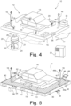
- the Figure 4 shows a perspective view of a vehicle 12, which is part of a conveyor system 10 not according to the invention.
- vehicle 12 has a known workpiece holder 13, to which a workpiece to be machined, here also a motor vehicle 14 that has not yet been fully assembled, is attached.
- vehicle 12 also includes an assembly platform 15, which can be accessed by workers 16.
- the vehicle 12 also has its own drive, which includes four driving-rotating modules 20 in the exemplary embodiment shown.
- each driving-rotating module 20 has a motor unit 21 and a drive wheel 24 driven via a belt 22, which form a drive unit.
- This drive unit is rotatable relative to a holder 26 about a vertical axis 28, as is known in the prior art.
- the driving-rotating modules 20 are embedded in the mounting platform 15 so that only the drive wheels 24 protrude downwards.
- the drive units of all driving-rotating modules 20 are located in the Figure 4 shown rotational position with respect to its vertical axis 28, the vehicle 12 moves along its longitudinal direction when the drive wheels 24 rotate, as indicated by an arrow 30. If the drive units are all rotated by 90° with respect to their vertical axis 28, the vehicle 12 can drive perpendicular to its longitudinal direction 30 from a standstill, ie without first cornering, as indicated by a dotted arrow 32. By appropriately controlling the driving-rotating modules 20, rotations on the spot or diagonal movements can also be realized.
- control unit 36 Integrated into the assembly platform 15 is a control unit 36, which communicates wirelessly with a central control device 38 of the conveyor system 10.
- the control unit 36 includes a navigation system, in which the vehicle 12 can orient itself in a production hall, and a collision avoidance device. Control units 36 with these functions are known from free-moving transport systems (AGVs), which is why they will not be discussed in more detail here.
- AGVs free-moving transport systems
- the vehicle 12 is thereby able to move freely between several processing stations in a production hall.
- the vehicle 12 is not tied to a predetermined lane during such trips.
- controls in which the vehicles 12 move along predefined routes, which are specified by conductor tracks laid in the ground or similar, are also possible.
- the Figure 5 shows in one to the Figure 4
- the illustration shows an exemplary embodiment according to the invention for a vehicle 12.
- Sensors 40 are arranged on the front and side surfaces of the assembly platform 15 and serve for orientation and/or collision avoidance.
- the sensors 40 can be designed, for example, as laser scanners or as ultrasonic sensors.
- the top of the assembly platform 15 is covered by a touch-sensitive floor covering 42, which can be used to detect in a spatially resolved manner where the workers 16 are on the assembly platform 15 at a given time.
- touch-sensitive floor coverings are known from the prior art (cf. for example DE 10 2006 007 780 A1 ) and make it possible to detect the location of a worker 16 on the assembly platform 15 with a spatial resolution of less than 50 cm.
- pressure detection cells such as those from the DE 10 2011 105 595 A1 are known, the pressure exerted by the workers 16 on the floor covering 42 can also be recorded.
- FIG. 5 A worker 16 is shown on the right, who carries two identification elements 44a, 44b with him.
- the identification elements 44a, 44b can, for example, be incorporated into the sole of a shoe or into the pocket of a jacket and designed as RFID transponders.
- reading devices 46 which can be arranged at different locations on the vehicle 12, the identification information stored in the identification element 44a, 44b can be read out.
- the control unit 36 In cooperation with the touch-sensitive floor covering 42, the control unit 36 then not only knows where workers 16 are located on the assembly platform 15, but also who the workers 16 are. This can be used, for example, to only allow further processing or starting of the vehicle 12 when the worker or workers 16 intended for this purpose are on the assembly platform 15.
- a touch-sensitive screen 48 the workers 16 can intervene directly in the control of the vehicle 12. In addition to functions such as emergency stop or slow travel, new goals can also be specified. If a worker 16 determines, for example, that there is a defect indicated at 50 on the motor vehicle 14, the worker can use the touch-sensitive screen 48 to inform the control device 38 that a specific processing station needs to be approached again. The pre-planned route of the vehicle 12 is then rescheduled accordingly, which can also result in interventions in the routes of the other vehicles 12. The vehicle 12 with the affected motor vehicle 14 can then, for example, be moved out to the side and drive backwards in order to approach a specific processing station again. If the worker 16 so wishes, a processing station can also be approached that is specifically designed for post-processing. The decision as to which processing station should be approached in the event of a defect on the motor vehicle 14 can also be made by the central control device 38 or a manufacturing specialist responsible for production.
- a mobile input device 52 can also be used to provide the central control device 38 with certain information, e.g. B. to transmit a new destination.
- this communication can be bidirectional, so that the worker 16 can be shown, for example, whether the desired processing station can be approached immediately or whether this is only possible at a later point in time.
- the driving-rotating modules 20 of the vehicle 12 are supplied with electrical energy by an accumulator.
- the mounting platform 15 has lateral sliding contacts 54, against which a counter contact 56 is brought into contact in a specific charging position of the vehicle 12. The battery can then be charged while standing via the sliding contacts 54.
- the vehicle 12 also has the option of electrically charging the battery while driving.
- strip-shaped charging contacts 58 are embedded on the floor of the production hall, which rest on corresponding mating contacts of the vehicle 12. Particularly in production in which the vehicles 12 are in motion very frequently, downtimes of the vehicles 12 due to the required charging processes can be reduced or even completely avoided.
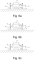
- the workpiece holder of the vehicles 12 can also be designed as a lifting table 130, as is the case Figures 6a to 6c in a rear view of a vehicle 12 for different lifting heights. This allows the motor vehicle 14 to be positioned at different heights above the assembly platform 15, so that the workers 16 can carry out all the necessary processing steps comfortably while standing.
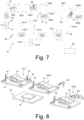
- the Figure 7 shows a schematic top view of a conveyor system 10 according to the invention, in which several vehicles and several processing stations 1801 to 1816 indicated by dashed lines can be seen. There are vehicles 12 in many processing stations 1801 to 1816; on the right edge of the Figure 7 a vehicle 12 can be seen while cornering between two processing stations 1807 and 1810.
- the vehicles drive on a route network 60, in which they orient themselves with the help of navigation devices such as radio-based navigation systems, laser scanners, cameras or ultrasonic sensors.
- navigation devices such as radio-based navigation systems, laser scanners, cameras or ultrasonic sensors.
- a receiving station 63 is shown, in which the motor vehicles 14 are placed on the workpiece holder 13 of a waiting vehicle 12. However, the workers 16 only enter the vehicle 12 after it has reached the first top left in the Figure 7 has reached the processing station 1801 shown. The vehicle 12 remains in this first processing station until the processing planned there is completed. The workers can signal this with a “done” signal on the touch-sensitive screen 48. Alternatively, a fixed cycle can also be specified, after which the vehicle 12 moves out of the first processing station 18. The workers 16 can now remain on the vehicle 12 and continue processing as it advances to the next processing station 1802.
- a robot 64 supports the processing.
- the workers 16 must now be sufficiently far away from the robot 64 so that they are not endangered by the movements of the robot arm.
- Robot 64 will be like this controlled by the central control device 38 so that it only starts processing when the two workers 16 have established a sufficiently large distance from the robot 64. This is signaled to the central control device 38 by the touch-sensitive floor covering 42 of the vehicle 12.
- the third processing station 1803 is located at the entrance to a parallel area 65, which includes three processing stations 1804, 1805 and 1806 that are parallel to each other. In these processing stations, processing steps are carried out that are not required for all motor vehicles 14. For example, a sunroof can be installed in one of the three parallel processing stations, while roof rails are placed in another. Depending on how the motor vehicle 14 to be manufactured is configured, the vehicle 12 moves from the third processing station 1803 to one of the three parallel processing stations 1804, 1805 or 1806.
- the vehicle that transports the motor vehicle in question can leave the processing area 1807 and be fed back to the processing area 1807 via a return path 66.
- subsequent vehicles 12 do not have to wait for the completion of processing of a motor vehicle 14 that is being transported by a vehicle 12 in front.
- the vehicle 12 thus leaves them on it overtake the following vehicles 12 by cutting into the return route 66 and then inserting itself again into the processing area 187 by moving laterally.
- processing station 1813 This is followed by the processing station 1813, from where the vehicles 12 drive either directly or via a processing station 1814 to a delivery station 67, in which the motor vehicle 14 is removed.
- a blockage 68 is indicated, which is located on the direct route between the processing station 1813 and the delivery station 67.
- the vehicles 12 can therefore not use this part of the route network 60 indicated by 60. For this reason, all vehicles 12 are exceptionally guided via the processing station 1814.
- the Figure 8 shows an arrangement of several closely adjacent processing stations 1817 to 1819 in a perspective view.
- two workers 16 are on the assembly platform 15 and assemble 14 parts on the motor vehicle that are kept ready in the containers 34.
- a robot 64 exchanges an empty container 34 for a full container during processing by the worker 16 or provides parts to be installed.
- the robot 64 is used here to assemble motor vehicle doors 70 on the motor vehicle 14.
- the delivery station 67 is shown at the bottom left, in which the motor vehicles 14 are removed from the vehicles 12.
- the Figure 9 shows a rear view of a processing station 1820, in which two workers 16 are located on the assembly platform 15. At this processing station 1820 there is a tool 72 which is supplied with power via a cable 74.
- the Figure 10 shows a rear view of another processing station 1821, in which the processing is carried out entirely by robots 64.
- the robot 64 shown on the left uses motor vehicle doors 70, while the robot 64 shown on the right inserts a rectangular element in the rear area of the motor vehicle 14.
- no workers 16 may be on the assembly platform 15 for safety reasons. It can be seen that one foot of the robot 64 shown on the right extends far beyond the assembly platform 15, which would acutely endanger a worker.
- the Figure 11 shows a perspective view of a vehicle 12 that is composed of several subunits. These subunits are those shown Embodiment around a workpiece carrier unit 76 arranged in the middle of the vehicle 12, which carries the workpiece holder 13, and two platform units 78a, 78b which can be walked on by the workers 16 and which are each coupled to a long side of the workpiece carrier unit 76.
- the workpiece carrier unit 76 and the two platform units 78a, 78b each have their own chassis and drive, so that the three subunits can move independently of one another.
- the three subunits are controlled according to the principle of superordination/subordination.
- the higher-level unit is controlled in the same way as was explained in connection with the exemplary embodiments for the vehicles 12 described above.
- the higher-level unit can in particular have means for navigation and collision avoidance.
- the other two subunits, here the platform units 78a, 78b are operated as subordinate units. This means that they do not approach the destination independently of the higher-level unit, but rather follow the higher-level unit.
- the subordinate units have the distance sensors already mentioned and suitable control electronics, which ensure that they move alongside the workpiece holding unit 76, without significantly changing their relative position to the workpiece carrier unit 76.
- the workpiece carrier unit 76 - can send a request command to the control device 38. This determines which platform units are available and instructs the selected platform units to automatically move to the workpiece carrier unit 76. As soon as the two platform units 78a, 78b have assumed their correct position relative to the workpiece carrier unit 76, the system switches to the principle of superordination/subordination, in which the platform units 78a, 78b follow the workpiece carrier unit 76.
- the Figure 12 shows in one to the Figure 7 leaning representation a conveyor system 10, in which the vehicles 12 in the Figure 11 are made up of three subunits as shown. It can be seen that in the processing station 1806 the right platform unit 78a, viewed in the direction of travel, has been uncoupled. As a result, the right side of the motor vehicle 14 is exposed so that processing can be carried out in the lower region of the motor vehicle 14 without the motor vehicle 14 having to be lifted beforehand using a lifting device.
- the uncoupled platform unit 78a is returned along a return route 81, integrated into a queue and coupled to another vehicle workpiece carrier unit 76, which passes through the processing stations 1801 to 1813 at a later point in time.
- the Figure 13 shows a rear view of a processing station 1821, both platform units 78a, 78b being uncoupled from the vehicle 12.
- the motor vehicle 14 is therefore only transported by the workpiece carrier unit 76. In this way, the wheel cutouts of the motor vehicle 14 are freely accessible, so that assembly robots 64 can easily attach the wheels 80 provided to the axles of the motor vehicle 14.
- the Figure 14 shows a variant in which only one platform unit 78a is provided, which is shorter than the workpiece carrier unit 76 in the longitudinal direction of the vehicle 12.
- the platform unit 78b can be controlled to move past the workpiece support unit 76 at a close distance, as shown in FIG Figure 14 is indicated by a double arrow.
- This relative movement is also possible when the workpiece carrier unit 76 is in motion.
- a worker 16 located on the platform unit 78a is guided past the motor vehicle 14 evenly or at a desired speed. In this way, he can carry out processing steps on the motor vehicle 14 that are difficult to accomplish if the worker 16 has to carry out this relative movement himself.
- the worker 16 can, for example, kneel on the platform 78a and drive past the workpiece carrier unit 76 in order to attach a low-lying decorative strip or similar to the body.
- FIG 15 is in a to the Figure 11
- a further variant is shown in the leaning illustration, in which the two platform units 78a, 78b each have a lateral recess 82a and 82b, respectively.
- the shape of the recesses 82a, 82b is chosen so that the centrally arranged workpiece carrier unit 76 can be inserted laterally therein. In this way, a positive connection is achieved between the workpiece carrier unit 76 and the two adjacent platform units 78a, 78b, thereby increasing the stability of the assembly platform.
- either the workpiece carrier unit 76 as a higher-level unit can carry the two non-driven platform units 78a, 78b, or vice versa, the two subordinate units 78a, 78b carry the workpiece support unit 76 accommodated between them.
- the Figure 16 shows in one to the Figure 7 Based on the illustration, a conveyor system 10 according to another exemplary embodiment, in which the processing stations are no longer located at permanently fixed locations within a production area 84, but can be variably distributed within certain limits within a predetermined production area 84. These limits are set in particular by the unchangeable building infrastructure, such as the location of supply connections or fixed conveyor systems such as overhead conveyors.
- FIG. 16 On the left, the receiving station 63 and the delivery station 67 are shown, in which the motor vehicle 14 is picked up or delivered.
- a first group of processing stations 1822a to 1822f is shown, in which different processing steps are carried out. These processing steps may be selected to be mutually exclusive, for example, assembly of a folding roof in processing station 1822a and assembly of a power sunroof in processing station 1822b.
- the infrastructure for the individual processing stations 1822a, which are in the Figure 16 is not shown, can preferably also be moved on vehicles and is suitably delivered to the processing stations.
- a similar group with several processing stations 1823a to 1823l is further to the right in the Figure 16 shown. There are no extra routes because vehicles choose their own route.
- processing station 1824 At the bottom of the manufacturing area 84 there is a processing station 1824, which is uniform in the sense that the same processing steps are carried out at all locations. However, this processing station 1824 can also be spatially moved or changed in size.
- These mobile processing stations 1822 to 1824 make it possible to react flexibly to changing requirements in the production process. For example, if fewer motor vehicles with a sliding roof and more motor vehicles with a folding roof are required, processing stations for assembling a sunroof can be converted into processing stations for assembling a folding roof. If vehicles with a sliding roof are no longer manufactured, the relevant processing stations can be dismantled and the remaining processing stations can be relocated if necessary in order to create clear travel paths between the processing stations.
Landscapes
- Engineering & Computer Science (AREA)
- Mechanical Engineering (AREA)
- Manufacturing & Machinery (AREA)
- Chemical & Material Sciences (AREA)
- Combustion & Propulsion (AREA)
- Transportation (AREA)
- Automobile Manufacture Line, Endless Track Vehicle, Trailer (AREA)
- Automatic Assembly (AREA)
- Control Of Position, Course, Altitude, Or Attitude Of Moving Bodies (AREA)
Description
Die Erfindung betrifft ein Fördersystem und ein Verfahren zum gleichzeitigen Transport von Kraftfahrzeugen oder anderen Werkstücken und von Werkern gemäß den Oberbegriffen der Ansprüche 1 und 12.The invention relates to a conveyor system and a method for the simultaneous transport of motor vehicles or other workpieces and workers according to the preambles of
Derartige Fördersysteme werden insbesondere bei der Endmontage von Kraftfahrzeugen, großen Haushaltsgeräten oder von Maschinen eingesetzt, die in großen Stückzahlen hergestellt werden.Such conveyor systems are used in particular in the final assembly of motor vehicles, large household appliances or machines that are manufactured in large quantities.
Bei der Endmontage von Werkstücken werden häufig Fördersysteme eingesetzt, bei denen die Werker über einen längeren Zeitraum gemeinsam mit den Werkstücken transportiert werden. Auf diese Weise können die Werker Arbeiten an den Werkstücken vornehmen, ohne neben den Werkstücken herlaufen zu müssen.During the final assembly of workpieces, conveyor systems are often used in which the workers are transported together with the workpieces over a longer period of time. In this way, workers can carry out work on the workpieces without having to walk next to the workpieces.
Die Fahrzeuge dieser bekannten Fördersysteme weisen eine Werkstückaufnahme zur Befestigung des Werkstücks, eine für die Werker begehbare Montageplattform und ein Fahrwerk mit Rädern auf. Üblicherweise bilden die Fahrzeuge einen Schubverband, während sie Werker gemeinsam mit den Werkstücken transportieren. Das jeweils letzte Fahrzeug schiebt dabei die vorausfahrenden Fahrzeuge von hinten an, wobei es durch ortsfeste externe Antriebsmittel angetrieben wird. Bei diesen Antriebsmitteln kann es sich beispielsweise um Reibräder handeln, die von außen an den Längsseiten der jeweils letzten Montageplattform angreifen und auf diese Weise die für die Vorwärtsbewegung des gesamten Schubverbands erforderliche Schubkraft aufbringen. Durch das Anschieben von hinten wird erreicht, dass die Montageplattformen innerhalb des Schubverbands spaltfrei aneinander angrenzen, sodass die Werker gefahrlos auf benachbarte Montageplattformen überwechseln könne. Am Ende eines Fertigungsabschnitts wird der Schubverband häufig wieder aufgelöst. Hierzu werden die Werkstücke üblicherweise von den Fahrzeugen abgenommen. Die leeren Fahrzeuge werden anschließend in einer Umsetzstation vertikal oder horizontal umgesetzt und laufen auf einer anderen Förderstrecke leer zurück. Anstatt den Schubverband dauerhaft aufzulösen, können die Fahrzeuge auch kurzfristig vereinzelt und auf einer Kurvenfahrt zu einem weiteren Fertigungsabschnitt gefördert werden, wo sie erneut einen Schubverband bilden.The vehicles of these known conveyor systems have a workpiece holder for fastening the workpiece, an assembly platform that the workers can walk on and a chassis with wheels. The vehicles usually form a push group while transporting workers together with the workpieces. The last vehicle pushes the vehicles in front from behind, being driven by stationary external drive means. These drive means can be, for example, friction wheels that act from the outside on the long sides of the last assembly platform and in this way apply the thrust force required for the forward movement of the entire push assembly. By pushing from behind, the assembly platforms within the push assembly are adjacent to each other without any gaps, so that the workers can safely move to neighboring assembly platforms. At the end of a production phase, the shear assembly is common dissolved again. For this purpose, the workpieces are usually removed from the vehicles. The empty vehicles are then moved vertically or horizontally in a transfer station and return empty on another conveyor route. Instead of permanently dissolving the push group, the vehicles can also be separated at short notice and transported on a curve to another production section, where they form a push group again.
Aus der
Ein ähnliches Fördersystem ist aus der
Einen anderen Weg zur Gewichtsverringerung beschreibt die
Das Fahren im Schubverband bringt jedoch auch einige Nachteile mit sich. So werden beispielsweise Kraftfahrzeuge heute immer stärker individualisiert. Dadurch kommt es immer häufiger vor, dass einzelne Kraftfahrzeuge erheblich mehr oder andere Bearbeitungsschritte benötigen als andere Kraftfahrzeuge des gleichen Models. Außerdem werden bereits jetzt bei einigen Herstellern unterschiedliche Modelle auf der gleichen Fertigungslinie montiert, um eine gleichmäßigere Auslastung zu ermöglichen. Bislang sind alle Bearbeitungsstationen hintereinander angeordnet, so dass jedes Kraftfahrzeug alle Bearbeitungsstationen durchläuft, auch wenn dort überhaupt keine Bearbeitung stattfindet.However, driving in a push convoy also has some disadvantages. Motor vehicles, for example, are becoming increasingly individualized today. As a result, it is becoming increasingly common for individual motor vehicles to require significantly more or different processing steps than other motor vehicles of the same model. In addition, some manufacturers are already producing different models on the same production line mounted to enable more even utilization. To date, all processing stations have been arranged one behind the other, so that every motor vehicle passes through all processing stations, even if no processing at all is taking place there.
Ähnliche Probleme stellen sich auch bei anderen Werkstücken, z. B. größeren Haushaltsgeräten oder Maschinen, die in großen Stückzahlen hergestellt werden.Similar problems also arise with other workpieces, e.g. B. larger household appliances or machines that are manufactured in large quantities.
Aus der
Aus der
Aufgabe der Erfindung ist es, ein Fördersystem und ein Verfahren zum gleichzeitigen Transport von Werkstücken und Werkern bereitzustellen, das besser an die modernen Produktionsabläufe angepasst ist.The object of the invention is to provide a conveyor system and a method for the simultaneous transport of workpieces and workers that is better adapted to modern production processes.
Erfindungsgemäß wird diese Aufgabe durch ein Fördersystem mit den Merkmalen des Anspruchs 1 gelöst. Vorteilhafte Ausführungsbeispiele des Fördersystems sind in den abhängigen Ansprüche 2 bis 11 angegeben.According to the invention, this object is achieved by a conveyor system with the features of claim 1. Advantageous embodiments of the conveyor system are specified in dependent claims 2 to 11.
Das erfindungsgemäße Fördersystem kombiniert damit die Vorteile beweglicher Montageplattformen und fahrerloser Transportsysteme (FTS), mit denen bislang ausschließlich Werkstücke, nicht aber Werker transportiert werden. Wie fahrerlose Transportsysteme können die erfindungsgemäßen Fahrzeuge eigenständig und ohne Schleppkabel fahren. Die Fahrzeuge verfügen deswegen über einen eigenen Antrieb und eine geeignete Energieversorgung, beispielsweise in Form eines Akkumulators. Je nach den spezifischen örtlichen Gegebenheiten und dem daran angepassten Steuerungssystem benötigen die erfindungsgemäßen Fahrzeuge in der Regel Navigationsmittel, damit sie selbstständig ihren Weg zur nächsten Bearbeitungsstation finden. Zur Ortung können beispielsweise funkbasierte Navigationssysteme, Ultraschall oder Laserscanner eingesetzt werden, die Winkel zu Reflexstreifen bestimmen, die an bestimmten Stellen entlang des Förderweges befestigt sind. Daneben kommt auch eine Navigation mithilfe von Fernsehkameras und Mustererkennung in Betracht. In den meisten Fällen wird man aus Sicherheitsgründen auch Mittel zur Hinderniserkennung vorsehen. Dabei kann es sich z. B. um einen Laserscanner handeln, der Hindernisse und insbesondere Personen erkennen und ein Abbremsen oder ein Ausweichmanöver veranlassen kann.The conveyor system according to the invention thus combines the advantages of movable assembly platforms and driverless transport systems (AGVs), which have so far only been used to transport workpieces, but not workers. Like driverless transport systems, the vehicles according to the invention can drive independently and without a trailing cable. The vehicles therefore have their own drive and a suitable energy supply, for example in the form of a battery. Depending on the specific local conditions and the control system adapted to them, the vehicles according to the invention generally require navigation means so that they can operate independently Find your way to the next processing station. For location purposes, radio-based navigation systems, ultrasound or laser scanners can be used, for example, which determine angles to reflective strips that are attached at certain points along the conveyor path. Navigation using television cameras and pattern recognition can also be considered. In most cases, means of obstacle detection will also be provided for safety reasons. This can be e.g. B. is a laser scanner that can detect obstacles and especially people and initiate braking or evasive maneuvers.
Mit derart ausgestatteten Fahrzeugen ist es möglich, individuell unterschiedliche Abfolgen von Bearbeitungsstationen abzufahren. Anders als bei den herkömmlichen Fördersystemen, bei denen sich alle Fahrzeuge hintereinander im Schubverband bewegen, müssen die Fahrzeuge somit nur solche Bearbeitungsstationen anfahren, die zu der Bearbeitung des transportierten Werkstücks tatsächlich erforderlich sind. Die Werker können während der Fahrten zwischen den Bearbeitungsstationen auf der Montageplattform bleiben und die Zeit für die Bearbeitung des Werkstücks nutzen. Je nach den Anforderungen des Einzelfalls kann es jedoch sinnvoller sein, wenn die Werker vor allen oder vor bestimmten Fahrten die Montageplattform verlassen. Das Fahrzeug transportiert dann nur das Werkstück, aber nicht die Werker zur nächsten Bearbeitungsstation.With vehicles equipped in this way, it is possible to drive through individually different sequences of processing stations. In contrast to conventional conveyor systems, in which all vehicles move one behind the other in a push train, the vehicles only have to drive to those processing stations that are actually required to process the transported workpiece. The workers can stay on the assembly platform while traveling between the processing stations and use the time to process the workpiece. However, depending on the requirements of the individual case, it may make more sense for the workers to leave the assembly platform before all or certain journeys. The vehicle then only transports the workpiece, but not the workers, to the next processing station.
Während beim Transport in einem Schubverband die Bearbeitungsstationen alle entlang einer Fertigungslinie angeordnet sind, können die Bearbeitungsstationen bei dem erfindungsgemäßen Fördersystem so verteilt angeordnet sein, dass sie teilweise nur durch eine Seitwärts- oder Kurvenfahrt, aber ohne Fahrtrichtungsumkehr von den Fahrzeugen angefahren werden können. Dadurch können sich - ähnlich wie in einem Rangierbahnhof - einzelne Fertigungslinien in mehrere Teillinien aufspalten und später wieder zusammengeführt werden.While the processing stations are all arranged along a production line during transport in a push unit, the processing stations in the conveyor system according to the invention can be arranged so that they can sometimes only be approached by the vehicles by driving sideways or around curves, but without reversing the direction of travel. This means that - similar to a marshalling yard - individual production lines can be split into several sub-lines and later merged again.
Im Gegensatz zu herkömmlichen Fertigungslinien müssen die Bearbeitungsstationen vom Grundsatz her nicht mehr entlang einer geraden, mäandrierenden oder wie auch immer gewundenen Linie im Wesentlichen hintereinander angeordnet sein. Das erfindungsgemäße Fördersystem ermöglicht es, die Bearbeitungsstationen völlig frei innerhalb eines vorgegebenen Fertigungsareals fahren zu lassen. Die Fertigungsabläufe müssen deswegen nicht mehr "linear" organisiert sein, sondern können auch -jedenfalls innerhalb gewisser-Grenzen frei variiert werden.In contrast to conventional production lines, the processing stations no longer have to be arranged essentially one behind the other along a straight, meandering or however winding line. The conveyor system according to the invention makes it possible to move the processing stations completely freely within one to drive to the specified production area. The production processes therefore no longer have to be organized in a “linear” manner, but can also be varied freely - at least within certain limits.
Während bislang beispielsweise festgelegt sein musste, ob zuerst eine Türverkleidung oder ein Scheibenwischer bei einem Kraftfahrzeug eingebaut werden muss, kann diese Entscheidung nun davon abhängig gemacht werden, ob die betreffende Bearbeitungsstation gerade von einem anderen Fahrzeug besetzt ist oder nicht. Die Fahrzeuge können beispielsweise so gesteuert werden, dass sie der Steuerungseinrichtung zu vorgegebenen Zeitpunkten oder ereignisgesteuert über die Art und den Fertigungszustand des jeweils transportierten Werkstücks informieren. Die Steuerungseinrichtung legt dann für jedes Fahrzeug unter Berücksichtigung des Belegungszustands der Bearbeitungsstationen mit anderen Fahrzeugen zumindest eine als nächste anzufahrende Bearbeitungsstation und vorzugsweise die Abfolge aller noch anzufahrenden Bearbeitungsstationen fest.While it previously had to be determined, for example, whether a door panel or a windshield wiper had to be installed in a motor vehicle first, this decision can now be made dependent on whether the processing station in question is currently occupied by another vehicle or not. The vehicles can, for example, be controlled in such a way that they inform the control device at predetermined times or in an event-controlled manner about the type and production status of the workpiece being transported. The control device then determines for each vehicle, taking into account the occupancy status of the processing stations with other vehicles, at least one processing station to be approached next and preferably the sequence of all processing stations still to be approached.
Erhält die Steuerungseinrichtung keine Informationen über die Art und den Fertigstellungszustand des jeweils transportierten Werkstücks, so kann sie nicht wissen kann, ob ein bestimmter Bearbeitungsschritt vollständig abgeschlossen wurde, ein vollständiger Abschluss (z. B. wegen eines fehlenden Teils) nicht möglich war oder die Bearbeitung zwar durchgeführt wurde, aber mit einem fehlerhaften Ergebnis. Erst mit diesen Informationen kann die Steuerungseinrichtung eine sinnvolle Entscheidung darüber treffen, welche Bearbeitungsstation als nächste angefahren werden soll.If the control device does not receive any information about the type and state of completion of the workpiece being transported, it cannot know whether a specific processing step was completely completed, whether complete completion was not possible (e.g. due to a missing part) or whether the processing was carried out, but with an incorrect result. Only with this information can the control device make a sensible decision about which processing station should be approached next.
Im Prinzip ist jedoch auch denkbar, mehr "Intelligenz" auf die Fahrzeuge selbst zu verlagern. In diesem Fall kann die Steuerungseinrichtung beispielsweise die Fahrzeuge über den Belegungszustand aller Bearbeitungsstationen informieren. Die Fahrzeuge entscheiden dann selbstständig, welche Bearbeitungsstationen sie als nächste aufsuchen. Die Fahrzeuge teilen der Steuerungseinrichtung diese Entscheidung mit, so dass diese die betreffende Bearbeitungsstation für einen gewissen Zeitraum als belegt ansehen kann und diese Information an die übrigen Fahrzeuge verteilt.In principle, however, it is also conceivable to shift more “intelligence” to the vehicles themselves. In this case, the control device can, for example, inform the vehicles about the occupancy status of all processing stations. The vehicles then decide independently which processing stations they will visit next. The vehicles inform the control device of this decision, so that it can consider the processing station in question to be occupied for a certain period of time and distribute this information to the other vehicles.
In Betracht kommt ferner, auch die Orte der Bearbeitungsstationen innerhalb eines vorgegebenen Fertigungsareals zu variieren. Die Bearbeitungsstationen sind dann selbst als mobile Einheiten ausgelegt, die innerhalb des Fertigungsareals innerhalb gewisser Grenzen verlagert werden können, um sich variabel an die Zahl und Art der zu fertigenden Werkstücke anzupassen. Die selbstfahrenden Fahrzeuge des erfindungsgemäßen Fördersystems sind dazu in der Lage, sich auch in einer solchen variable Anordnung von Bearbeitungsstationen jederzeit orientieren zu können und den Weg zu der jeweils nächsten Bearbeitungsstation aufzufinden.It is also possible to vary the locations of the processing stations within a given production area. The processing stations themselves are then designed as mobile units that can be relocated within the production area within certain limits in order to adapt variably to the number and type of workpieces to be manufactured. The self-propelled vehicles of the conveyor system according to the invention are able to orientate themselves at any time even in such a variable arrangement of processing stations and to find the way to the next processing station.
Da Kurvenfahrten vergleichsweise viel freien Raum benötigen, können die Fahrzeuge jeweils einen omnidirektionalen Antrieb haben, mit dem die Fahrzeuge aus dem Stand heraus in eine beliebige Richtung fahren können. Die omnidirektionalen Antriebe können beispielsweise Allseitenräder, Mecanum-Räder oder Fahr-Dreh-Module umfassen, wie dies an sich im Stand der Technik bekannt ist.Since cornering requires a comparatively large amount of free space, the vehicles can each have an omnidirectional drive, with which the vehicles can drive in any direction from a standstill. The omnidirectional drives can include, for example, all-side wheels, Mecanum wheels or driving-rotating modules, as is known in the prior art.
Mit einem solchen omnidirektionalen Antrieb können die Fahrzeuge beispielsweise auf der Stelle gedreht oder gewendet werden. Außerdem ist es möglich, die Fahrzeuge seitlich ohne Kurvenfahrt zu versetzen. Dadurch können sie raumsparend aus einer Linie herausgelöst werden, um zu einer bestimmten Bearbeitungsstation zu fahren oder nachfolgende Fahrzeuge überholen zu lassen. Umgekehrt können die Fahrzeuge auch so gesteuert werden, dass ein erstes Fahrzeug ein zweites Fahrzeug überholt, während sich das zweite Fahrzeug in einer Bearbeitungsstation befindet.With such an omnidirectional drive, the vehicles can be turned or turned on the spot, for example. It is also possible to move the vehicles sideways without cornering. This means they can be separated from a line to save space in order to drive to a specific processing station or allow subsequent vehicles to overtake. Conversely, the vehicles can also be controlled so that a first vehicle overtakes a second vehicle while the second vehicle is in a processing station.
Vor allem dann, wenn Werker sich während der Fahrt der Fahrzeuge auf den Montageplattformen befinden, muss sichergestellt sein, dass Werker nicht beim Anfahren, Bremsen oder anderen Fahrmanövern gefährdet werden. Erfindungsgemäß haben die Fahrzeuge deswegen jeweils eine Detektionseinrichtung, die dazu eingerichtet ist, die Anwesenheit eines Werkers auf der jeweiligen Montageplattform zu detektieren. Bei der Detektionseinrichtung kann es sich beispielsweise um einen berührungsempfindlichen Bodenbelag handeln, der zumindest einen Teil der Montageplattform überdeckt. Die Steuerungseinrichtung kann dabei so eingerichtet sein, dass für den Fall, dass sich ein Werker auf der Montageplattform befindet, das Fahrzeug entweder gar nicht in Bewegung setzen darf oder bestimmte Fahrmanöver (Beschleunigen, Abbremsen, Kurvenfahrten etc.) nur nach vorheriger Abgabe eines optischen oder akustischen Warensignals erfolgen dürfen. Ferner kommt in Betracht, bei Anwesenheit eines Werkers auf der Montageplattform bestimmte Fahrmanöver nur mit Einschränkung durchzuführen. So kann beispielsweise festgelegt sein, dass die bei den Fahrmanövern auftretenden Beschleunigungen in Längs- oder Querrichtung unterhalb vorgegebener Grenzwerte bleiben müssen.Especially when workers are on the assembly platforms while the vehicles are moving, it must be ensured that workers are not endangered when starting, braking or other driving maneuvers. According to the invention, the vehicles therefore each have a detection device which is set up to detect the presence of a worker on the respective assembly platform. The detection device can be, for example, a touch-sensitive floor covering that covers at least part of the assembly platform. The control device can be set up in such a way that if a worker is on the assembly platform, the vehicle is either not allowed to move at all or Certain driving maneuvers (accelerating, braking, cornering, etc.) may only be carried out after a visual or acoustic goods signal has been given. Furthermore, it is possible to only carry out certain driving maneuvers with restrictions when a worker is present on the assembly platform. For example, it can be specified that the accelerations that occur during driving maneuvers in the longitudinal or transverse direction must remain below predetermined limit values.
Vorzugsweise ist die Detektionseinrichtung dazu eingerichtet, nicht nur die Anwesenheit eines Werkers an sich, sondern auch seinen Ort auf der jeweiligen Montageplattform zu detektieren. Dann kann die Steuerung des Fahrzeugs zusätzlich von dieser Ortsinformation abhängig gemacht werden. Wenn sich ein Werker beispielsweise am in Fahrtrichtung hinten liegenden Ende der Montageplattform befindet, kann eine zusätzliche Beschleunigung schnell dazu führen, dass der Werker über die hintere Kante der Montageplattform fällt. In einem solchen Falle sollte der Beschleunigungsvorgang besonders behutsam durchgeführt werden, oder es ist mit zusätzlichen Maßnahmen sicherzustellen, dass der Werker sich auf der Montageplattform festhält, bevor der Beschleunigungsvorgang beginnt.The detection device is preferably set up to detect not only the presence of a worker per se, but also his location on the respective assembly platform. The control of the vehicle can then also be made dependent on this location information. For example, if a worker is at the rear end of the assembly platform in the direction of travel, additional acceleration can quickly cause the worker to fall over the rear edge of the assembly platform. In such a case, the acceleration process should be carried out particularly carefully, or additional measures should be taken to ensure that the worker holds on to the assembly platform before the acceleration process begins.
Je höher die Ortsauflösung der Detektionseinrichtung ist, desto besser kann die Steuerungseinrichtung die Fahrmanöver der Fahrzeuge davon abhängig machen, wo der oder die Werker sich auf der Montageplattform befinden. Idealerweise beträgt die Ortsauflösung mindestens 50 cm.The higher the spatial resolution of the detection device, the better the control device can make the driving maneuvers of the vehicles dependent on where the worker or workers are located on the assembly platform. Ideally, the spatial resolution is at least 50 cm.
Vorteilhaft ist es außerdem, wenn die Detektionseinrichtung ein vom Werker zu tragendes Identifikationselement und eine am Fahrzeug angeordnete Leseeinrichtung umfasst, die dazu eingerichtet ist, auf dem Identifikationselement gespeicherte Informationen berührungslos zu lesen. Auf diese Weise kann die Detektionseinrichtung feststellen, ob sich der richtige Werker auf der Montageplattform des betreffenden Fahrzeugs befindet. Da der Fahrbetrieb insgesamt durch das selbsttätige Anfahren unterschiedlicher Bearbeitungsstationen komplex wird, ist es wichtig, dass die Werker verifizieren können, dass sie sich zu einem gegebenen Zeitpunkt auf dem richtigen Fahrzeug befinden. Die Steuerungseinrichtung kann die Fahrzeuge dann beispielsweise so steuern, dass die Fahrzeuge erst dann anfahren dürfen, wenn sich alle für den nächsten Bearbeitungsschritt benötigten Werker auf der Montageplattform befinden. Außerdem können Warnhinweise individuell für einzelne Werker generiert werden. Bei dem Identifikationselement kann es sich beispielsweise um einen RFID-Transponder, dessen Informationen per Funk ausgelesen werden, oder um einen QR-Code handeln, dessen Informationen optisch abgelesen werden.It is also advantageous if the detection device comprises an identification element to be worn by the worker and a reading device arranged on the vehicle, which is set up to read information stored on the identification element in a contactless manner. In this way, the detection device can determine whether the correct worker is on the assembly platform of the vehicle in question. Since the driving operation as a whole becomes complex due to the automatic approach to different processing stations, it is important that the workers can verify that they are on the right vehicle at a given time. The control device can then, for example, control the vehicles in such a way that the vehicles are only allowed to drive off when all workers required for the next processing step are present on the mounting platform. In addition, warnings can be generated individually for individual workers. The identification element can be, for example, an RFID transponder whose information is read out via radio, or a QR code whose information is read optically.
Es ist außerdem möglich, alle oder zumindest alle größeren zu verbauenden Teile mit einem RFID-Transponder oder einem anderen Identifikationselement zu versehen, das berührungslos gelesen werden kann. Auf diese Weise lässt sich durch Abrufen aller Identifizierungsinformationen erkennen, ob in dem betreffenden Werkstück die richtigen Teile verbaut wurden und/oder die für den Einbau bereitgehaltenen Teile tatsächlich zum Werkstück passen. Wenn das Fertigungsareal über ein dichtes Netz von Leseeinrichtungen verfügt, kann auch eine vollständige Erfassung aller Werkstücke, Teile und Werker stattfinden. Die dabei erzieltbare Ortsauflösung wird durch die Dichte der Leseeinrichtungen bestimmt.It is also possible to provide all or at least all larger parts to be installed with an RFID transponder or another identification element that can be read without contact. In this way, by retrieving all identifying information, it can be seen whether the correct parts have been installed in the workpiece in question and/or the parts held ready for installation actually fit the workpiece. If the production area has a dense network of reading devices, a complete recording of all workpieces, parts and workers can also take place. The spatial resolution that can be achieved is determined by the density of the reading devices.
Alternativ zu Detektionseinrichtungen auf den Fahrzeugen kann auch eine externe Detektion der Werker vorgesehen sein. So können beispielsweise im gesamten Fertigungsareal Kameras installiert sein, die alle Bereiche des Fertigungsareals überwachen, in denen sich Fahrzeuge befinden können. Vorzugsweise verfügen die Fahrzeuge zum Bereitstellen der für den Fahrbetrieb erforderlichen Energie über einen wiederaufladbaren elektrischen Energiespeicher, der während des Fahrens der Fahrzeuge aufladbar ist. Dadurch müssen die Fahrzeuge zum Aufladen der elektrischen Energiespeicher nicht eine Ladestation anfahren, sondern können während ihres Einsatzes im Fertigungsbetrieb aufgeladen werden. Denkbar ist jedoch selbstverständlich auch, dass der elektrische Energiespeicher eines Fahrzeugs nur dann aufgeladen wird, wenn das Fahrzeug steht. Dies kann gegebenenfalls auch in einer Bearbeitungsstation der Fall sein.As an alternative to detection devices on the vehicles, external detection of the workers can also be provided. For example, cameras can be installed throughout the entire production area to monitor all areas of the production area in which vehicles may be located. To provide the energy required for driving, the vehicles preferably have a rechargeable electrical energy storage device that can be charged while the vehicles are driving. This means that the vehicles do not have to drive to a charging station to charge the electrical energy storage devices, but can be charged while they are being used in the manufacturing plant. However, it is of course also conceivable that the electrical energy storage of a vehicle is only charged when the vehicle is stationary. If necessary, this can also be the case in a processing station.
Die Bearbeitungsstationen unterscheiden sich regelmäßig voneinander durch die dort angeordneten Werkzeuge und/oder Handhabungsgeräte und/oder Montageroboter. Ein weiteres Unterscheidungskriterium können Teile oder Materialien sein, die für die Fertigung benötigt und an den Bearbeitungsstationen bereitgestellt werden. Als Bearbeitungsstationen werden hier im weiteren Sinne auch solche Stationen angesehen, bei denen keine Bearbeitung des Werkstücks im engeren Sinne erfolgt, sondern lediglich Teile, Materialien oder Werkzeuge nachgefüllt, ausgetaucht oder entfernt werden.The processing stations regularly differ from one another in the tools and/or handling devices and/or assembly robots arranged there. Another distinguishing criterion can be parts or materials that are required for production and provided at the processing stations. In the broader sense, processing stations are also viewed here as stations where: The workpiece is not processed in the strict sense, but only parts, materials or tools are refilled, replaced or removed.
Vorzugsweise erstreckt sich die Montageplattform eines Fahrzeugs über seine gesamte Länge hinweg. In Betracht kommt jedoch auch, den Front- und/oder Heckbereich des Fahrzeugs mit stationären Aufbewahrungseinrichtungen zu versehen, die nicht begehbar sind.Preferably, the mounting platform of a vehicle extends over its entire length. However, it is also possible to provide the front and/or rear area of the vehicle with stationary storage facilities that cannot be accessed.
Durch die erfindungsgemäße Individualisierung der im Fördersystem durchgeführten Fahrten ist nicht ausgeschlossen, dass aufeinander folgende Fahrzeuge sich zeitweise während des Fahrens so berühren, dass sie einen Verband bilden. Bearbeitungsstationen, die von allen Fahrzeugen angefahren werden müssen, können dann wie bisher in einer Linie hintereinander angeordnet sein.Due to the individualization according to the invention of the trips carried out in the conveyor system, it cannot be ruled out that successive vehicles touch each other at times while driving in such a way that they form a group. Processing stations that must be approached by all vehicles can then be arranged in a line one behind the other, as before.
Bei einem vorteilhaften Ausführungsbeispiel weist mindestens ein Fahrzeug eine für einen sich auf der Montageplattform befindenden Werker zugängliche Eingabeeinrichtung auf, über die sich der Werker der Steuereinrichtung eine von dem betreffenden Fahrzeug noch anzufahrende Bearbeitungsstation vorgeben kann. Eine solche Eingabeeinrichtung kann stationär am Fahrzeug befestigt sein, aber auch schnurlos mit dem Fahrzeug oder direkt mit der Steuerungseinrichtung kommunizieren. Der Werker hat dann beispielsweise die Möglichkeit, eine Bearbeitungsstation erneut anzufahren, falls er einen Fertigungs- oder Montagefehler erkannt hat. Die Steuerungseinrichtung sorgt dafür, dass das betreffende Fahrzeug seinen Weg umdisponiert und die betreffende Bearbeitungsstation oder eine andere Bearbeitungsstation, in welcher der gleiche Bearbeitungsschritt durchgeführt werden kann, anfährt.In an advantageous exemplary embodiment, at least one vehicle has an input device that is accessible to a worker located on the assembly platform, via which the worker can specify to the control device a processing station to be approached by the vehicle in question. Such an input device can be attached to the vehicle in a stationary manner, but can also communicate wirelessly with the vehicle or directly with the control device. The worker then has the opportunity, for example, to approach a processing station again if he has detected a manufacturing or assembly error. The control device ensures that the vehicle in question reschedules its route and moves to the relevant processing station or another processing station in which the same processing step can be carried out.
Bei einigen Ausführungsbeispielen ist mindestens ein Fahrzeug aus mehreren Untereinheiten zusammengesetzt. Diese Untereinheiten sind quer zu einer Längsrichtung des Fahrzeugs nebeneinander angeordnet und lösbar miteinander gekuppelt, was sowohl mechanische, meist auf Formbeschluss beruhende Kupplungen als auch regelungstechnische Kupplungen umfasst, bei denen die Untereinheiten in einem konstanten Abstand oder sich leicht berührend nebeneinander herfahren. Die Untereinheiten weisen außerdem voneinander getrennte Fahrwerke auf, sodass die Untereinheiten nach Entkuppeln getrennt und unabhängig voneinander verfahrbar sind. Mindestens eine und vorzugsweise alle Untereinheiten hat außerdem einen eigenen Antrieb.In some embodiments, at least one vehicle is composed of multiple subunits. These subunits are arranged next to each other transversely to a longitudinal direction of the vehicle and are releasably coupled to one another, which includes both mechanical clutches, usually based on positive locking, as well as control clutches in which the subunits move next to each other at a constant distance or slightly touching each other. The subunits also have separate undercarriages, so that the subunits are separated after uncoupling and can be moved independently of each other. At least one and preferably all subunits also have their own drive.
Durch eine solche Unterteilung der Fahrzeuge in Untereinheiten kann die Flexibilität des Fördersystems nochmals erhöht werden. Das Abkuppeln von einer oder mehreren Untereinheiten kann beispielsweise dann zweckmäßig sein, wenn bei bestimmten Bearbeitungsvorgängen ein Zugang an Orten benötigt wird, die normalerweise von der Montageplattform ausgefüllt sind. Anstatt das Werkstück mit einer Hubvorrichtung anzuheben, können seitliche Untereinheiten der Montageplattform abgekoppelt und entfernt werden, um unten liegende Teile des Werkstücks besser erreichen zu können.By dividing the vehicles into subunits in this way, the flexibility of the conveyor system can be increased further. Uncoupling one or more subunits can be useful, for example, if certain machining operations require access to locations that are normally occupied by the assembly platform. Instead of lifting the workpiece with a lifting device, side subunits of the assembly platform can be uncoupled and removed to better reach parts of the workpiece below.
Günstig ist es dabei insbesondere, wenn eine der Untereinheiten eine Werkstückträgereinheit ist, welche die Werkstückaufnahme aufweist, und wenn eine andere Untereinheit eine Plattformeinheit ist, die zumindest im Wesentlichen frei für Werker begehbar ist. Dadurch werden die unterschiedlichen Funktionen der Fahrzeuge, nämlich der Transport der Werkstücke und der Transport der Werker, voneinander unabhängigen Untereinheiten zugewiesen.It is particularly advantageous if one of the subunits is a workpiece carrier unit that has the workpiece holder, and if another subunit is a platform unit that is at least essentially free for workers to walk on. As a result, the different functions of the vehicles, namely the transport of workpieces and the transport of workers, are assigned to independent subunits.
Besonders günstig ist es dabei, wenn das mindestens eine Fahrzeug zwei Plattformeinheiten aufweist, die zu beiden Seiten an die Werkstückträgereinheit angekuppelt sind. Bei entkoppelten Plattformeinheiten verbleibt dann eine schmalere Werkstückträgereinheit, die beispielsweise einer Bearbeitungsstation zugeführt werden kann, in der lediglich Roboter tätig sind und von der Werker aus Sicherheitsgründen fernzuhalten sind. Die Werker können dann auf den Plattformeinheiten zu einer anderen Werkstückträgereinheit fahren (und umgekehrt), um sich mit dieser zu verbinden. Wenn die Plattformeinheit eine Aussparung hat, in welche die Werkstückträgereinheit seitlich eingefügt ist, lassen sich die Untereinheiten besonders stabil durch Formschluss miteinander verbinden.It is particularly advantageous if the at least one vehicle has two platform units that are coupled to the workpiece carrier unit on both sides. With decoupled platform units, a narrower workpiece carrier unit then remains, which can be fed, for example, to a processing station in which only robots are active and from which workers must be kept away for safety reasons. The workers can then travel on the platform units to another workpiece carrier unit (and vice versa) to connect to it. If the platform unit has a recess into which the workpiece carrier unit is inserted laterally, the subunits can be connected to one another in a particularly stable manner by positive locking.
Mindestens eine Untereinheit kann dabei einen omnidirektionalen Antrieb haben, mit dem die Untereinheit aus dem Stand heraus in eine beliebige Richtung fahren kann.At least one subunit can have an omnidirectional drive, with which the subunit can move in any direction from a standing position.
Bei einem anderen Ausführungsbeispiel ist die Plattformeinheit entlang der Längsrichtung kürzer als die Werkstückträgereinheit. Dies eröffnet beispielsweise die Möglichkeit, die kürzere Plattformeinheit seitlich an der Werkstückträgereinheit entlang mit einer Geschwindigkeit zu verfahren, die sich von der Geschwindigkeit der Werkstückträgereinheit unterscheidet. Dadurch kommt es zu einer Relativbewegung zwischen der Werkstückträgereinheit und der Plattformeinheit, ohne dass die Plattformeinheit über das vordere oder hintere Ende der Werkstückträgereinheit hinausragt. Bei bestimmten Bearbeitungsvorgängen kann eine solche Relativbewegung erwünscht sein, z. B. wenn ein Werker an der Seite eines Kraftfahrzeugs eine Zierleiste befestigen soll. Die Plattformeinheit ist dann so an die Werkstückträgereinheit gekuppelt, dass sie bei geschlossener elektrisch-regelungstechnischer oder mechanischer Kupplung an der Werkstückträgereinheit entlang in Längsrichtung verfahrbar ist.In another embodiment, the platform unit is shorter along the longitudinal direction than the workpiece carrier unit. This opens up the possibility, for example, shorter platform unit to move laterally along the workpiece carrier unit at a speed that differs from the speed of the workpiece carrier unit. This results in a relative movement between the workpiece carrier unit and the platform unit without the platform unit protruding beyond the front or rear end of the workpiece carrier unit. Such a relative movement may be desirable for certain machining operations, e.g. B. if a worker has to attach a decorative strip to the side of a motor vehicle. The platform unit is then coupled to the workpiece carrier unit in such a way that it can be moved along the workpiece carrier unit in the longitudinal direction when the electrical control technology or mechanical coupling is closed.
Hinsichtlich des Verfahrens wird die eingangs gestellte Aufgabe gelöst durch ein Verfahren mit den Merkmalen des Anspruchs 12. Vorteilhafte Ausführungsbeispiele des Verfahrens sind in den abhängigen Ansprüche 13 bis 15 angegeben.With regard to the method, the task set out at the beginning is solved by a method with the features of
Die zum erfindungsgemäßen Fördersystem erläuterten vorteilhaften Wirkungen und Ausgestaltungen gelten insoweit entsprechend.The advantageous effects and configurations explained for the conveyor system according to the invention apply accordingly.
Eine Steuerungseinrichtung kann von den Fahrzeugen zu vorgegebenen Zeitpunkten oder ereignisgesteuert über die Art und den Fertigstellungszustand des jeweils transportieren Werkstücks informiert werden. Die Steuerungseinrichtung legt dann für jedes Fahrzeug unter Berücksichtigung des Belegungszutands der Bearbeitungsstationen mit anderen Fahrzeugen zumindest eine als nächste anzufahrende Bearbeitungstation und vorzugsweise die Abfolge aller noch anzufahrenden Bearbeitungsstationen fest.A control device can be informed by the vehicles at predetermined times or in an event-controlled manner about the type and state of completion of the workpiece being transported. The control device then determines for each vehicle, taking into account the occupancy status of the processing stations with other vehicles, at least one processing station to be approached next and preferably the sequence of all processing stations still to be approached.
Zumindest einige der Bearbeitungsstationen können so verteilt angeordnet sein, dass sie nur durch eine Seitwärts- oder Kurvenfahrt, aber ohne Fahrtrichtungsumkehr von den Fahrzeugen angefahren werden können.At least some of the processing stations can be arranged in such a way that the vehicles can only approach them by driving sideways or around curves, but without reversing the direction of travel.
Die Fahrzeuge können einen omnidirektionalen Antrieb haben, mit dem die Fahrzeuge aus dem Stand heraus in eine beliebige Richtung fahren können.The vehicles can have an omnidirectional drive, which allows the vehicles to move in any direction from a standstill.
Eine Detektionseinrichtung auf den Fahrzeugen detektiert die Anwesenheit eines Werkers auf der jeweiligen Montageplattform, und zwar vorzugsweise ortsaufgelöst, wobei die Ortsauflösung weiter vorzugsweise mindestens 50 cm beträgt.A detection device on the vehicles detects the presence of a worker on the respective assembly platform, preferably in a spatially resolved manner, the spatial resolution further preferably being at least 50 cm.
Wenn die Werker ein Identifikationselement tragen, so kann eine am Fahrzeug angeordnete Leseeinrichtung auf dem Identifikationselement gespeicherte Informationen berührungslos lesen.If the workers wear an identification element, a reading device arranged on the vehicle can read information stored on the identification element without contact.
Die Detektionseinrichtung kann einen berührungsempfindlichen Bodenbelag umfassen, der zumindest einen Teil der Montageplattform überdeckt.The detection device can include a touch-sensitive floor covering that covers at least part of the mounting platform.
Die Fahrzeuge können zum Bereitstellen der für den Fahrbetrieb erforderlichen Energie einen wiederaufladbaren elektrischen Energiespeicher haben, der während des Fahrens der Fahrzeuge aufgeladen wird.To provide the energy required for driving, the vehicles can have a rechargeable electrical energy storage device that is charged while the vehicles are being driven.
Die Bearbeitungsstationen können sich zumindest durch die dort angeordneten Werkzeuge und/oder Handhabungsgeräte und/oder Montageroboter voneinander unterscheiden.The processing stations can differ from one another at least in terms of the tools and/or handling devices and/or assembly robots arranged there.
Die Fahrzeuge können so gesteuert werden, dass ein erstes Fahrzeug ein zweites Fahrzeug überholt, während sich das zweite Fahrzeug in einer Bearbeitungsstation befindet.The vehicles can be controlled so that a first vehicle overtakes a second vehicle while the second vehicle is in a processing station.
Aufeinanderfolgende Fahrzeuge können sich zumindest zeitweise während des Fahrens berühren und dadurch einen Verband bilden.Successive vehicles can touch each other at least temporarily while driving and thereby form a group.
Mindestens ein Fahrzeug kann eine für einen Werker auf der Montageplattform zugängliche Eingabeeinrichtung aufweisen, über die der Werker der Steuereinrichtung eine von dem betreffenden Fahrzeug noch anzufahrende Bearbeitungsstation vorgeben kann.At least one vehicle can have an input device accessible to a worker on the assembly platform, via which the worker can specify to the control device a processing station to be approached by the vehicle in question.
Nachfolgend werden Ausführungsbeispiele der Erfindung anhand der Zeichnungen näher erläutert. In diesen zeigen:
- Figur 1
- ein aus dem Stand der Technik bekanntes Fördersystem, bei dem mehrere Fahrzeuge gemeinsam einen Schubverband bilden;
- Figur 2
- ein Fördersystem aus dem Stand der Technik, bei dem die Fahrzeuge am Ende eines Schubverbandes eine Kurvenfahrt durchführen und dann an das Ende eines parallelen und sich in der entgegengesetzten Richtung vorwärtsbewegenden Schubverbandes angesetzt werden;
- Figur 3
- ein Fördersystem nach dem Stand der Technik, bei dem zum Umsetzen am Ende eines Schubverbands die Fahrzeuge seitlich versetzt werden;
- Figur 4
- eine perspektivische Darstellung eines Fahrzeugs eines nicht erfindungsgemäßen Fördersystems, das einen omnidirektionalen Antrieb hat;
- Figur 5
- ein Ausführungsbeispiel für ein erfindungsgemäßes Fahrzeug, bei dem die Montageplattform mit einem berührungsempfindlichen Bodenbelag bedeckt ist;
- Figuren 6a-6c
- eine Rückansicht auf ein erfindungsgemäßes Fahrzeug, bei dem ein Kraftfahrzeug mithilfe eines Hubantriebs in unterschiedliche Bearbeitungshöhen überführt wird;
- Figur 7
- eine schematische Draufsicht auf ein erfindungsgemäßes Fördersystem, bei dem mehrere Fahrzeuge unterschiedliche Abfolgen von Bearbeitungsstationen anfahren;
- Figur 8
- eine perspektivische Ansicht mehrerer Fahrzeuge in unterschiedlichen Bearbeitungsstationen;
- Figur 9
- eine Rückansicht auf ein Fahrzeug in einer ersten Bearbeitungsstation, in der nur Werker tätig sind;
Figur 10- eine Rückansicht auf ein Fahrzeug in einer zweiten Bearbeitungsstation, in der nur Roboter tätig sind;
- Figur 11
- eine perspektivische Darstellung eines Fahrzeugs gemäß einem anderem Ausführungsbeispiel, bei dem das Fahrzeug in mehrere selbstständig fahrende Untereinheiten aufteilbar ist;
Figur 12- eine an die
Figur 7 angelehnte Darstellung eines Fördersystems, in dem die in derFigur 11 gezeigten Fahrzeuge fahren; Figur 13- eine Bearbeitungsstation, die nur von einer Werkstückträgereinheit angefahren wird;
Figur 14- eine perspektivische Darstellung eines Fahrzeugs, das aus einer größeren Werkstückträgereinheit und einer kürzeren Plattformeinheit zusammengesetzt ist;
Figur 15- eine perspektivische Darstellung eines Fahrzeugs gemäß einem weiteren Ausführungsbeispiel, bei dem eine Werkstückträgereinheit in seitliche Aussparungen zweier Plattformeinheiten eingreift;
- Figure 16
- eine an die
Figur 7 angelehnte Darstellung eines Fördersystems gemäß einem weiteren Ausführungsbeispiels, bei dem die Bearbeitungsstationen für die Fahrzeuge innerhalb eines Fertigungsareals innerhalb gewisser Grenzen frei wählbar sind.
- Figure 1
- a conveyor system known from the prior art, in which several vehicles together form a push group;
- Figure 2
- a conveyor system from the prior art, in which the vehicles make a curve at the end of a push train and then to the at the end of a parallel push convoy moving forward in the opposite direction;
- Figure 3
- a conveyor system according to the prior art, in which the vehicles are moved laterally at the end of a push convoy;
- Figure 4
- a perspective view of a vehicle of a conveyor system not according to the invention, which has an omnidirectional drive;
- Figure 5
- an embodiment of a vehicle according to the invention, in which the mounting platform is covered with a touch-sensitive floor covering;
- Figures 6a-6c
- a rear view of a vehicle according to the invention, in which a motor vehicle is transferred to different processing heights using a lifting drive;
- Figure 7
- a schematic top view of a conveyor system according to the invention, in which several vehicles approach different sequences of processing stations;
- Figure 8
- a perspective view of several vehicles in different processing stations;
- Figure 9
- a rear view of a vehicle in a first processing station in which only workers are working;
- Figure 10
- a rear view of a vehicle in a second processing station in which only robots are active;
- Figure 11
- a perspective view of a vehicle according to another exemplary embodiment, in which the vehicle can be divided into several self-driving subunits;
- Figure 12
- one to the
Figure 7 based representation of a support system in which theFigure 11 drive the vehicles shown; - Figure 13
- a processing station that is only approached by one workpiece carrier unit;
- Figure 14
- a perspective view of a vehicle composed of a larger workpiece carrier unit and a shorter platform unit;
- Figure 15
- a perspective view of a vehicle according to a further exemplary embodiment, in which a workpiece carrier unit engages in lateral recesses in two platform units;
- Figure 16
- one to the
Figure 7 Representation of a conveyor system according to a further exemplary embodiment, in which the processing stations for the vehicles within a production area can be freely selected within certain limits.
Die
Am Ende der in der
Die
Eine weitere Variante aus dem Stand der Technik ist in der
Bei allen in den
Die
Wie in der vergrößerten Darstellung erkennbar ist, weist jedes Fahr-Dreh-Modul 20 eine Motoreinheit 21 und ein über einen Riemen 22 angetriebenes Antriebsrad 24 auf, die eine Antriebseinheit bilden. Diese Antriebseinheit ist relativ zu einer Halterung 26 um eine vertikale Achse 28 drehbar, wie dies an sich im Stand der Technik bekannt ist. Zur Drehung der Antriebseinheit um die vertikale Achse 28 ist ein weiterer Motor vorgesehen, der in der
Befinden sich die Antriebseinheiten aller Fahr-Dreh-Module 20 in der in der
Auf der Oberseite der Montageplattform 15 finden sich mehrere Behälter 34, in denen zu montierende Teile, andere Materialien oder Werkzeuge bereitgehalten werden, welche die Werker 16 für die Bearbeitung benötigen.On the top of the
In die Montageplattform 15 integriert ist eine Steuereinheit 36, die mit einer zentralen Steuerungseinrichtung 38 des Fördersystems 10 drahtlos kommuniziert. Die Steuereinheit 36 umfasst ein Navigationssystem, bei dem sich das Fahrzeug 12 in einer Fertigungshalle orientieren kann, und eine Kollisionsvermeidungseinrichtung. Steuereinheiten 36 mit diesen Funktionen sind an und für sich von freifahrenden Transportsystemen (FTS) bekannt, weswegen hierauf an dieser Stelle nicht näher eingegangen wird. Das Fahrzeug 12 ist dadurch in der Lage, sich in einer Fertigungshalle frei zwischen mehreren Bearbeitungsstationen zu bewegen. Vorzugsweise ist das Fahrzeug 12 bei solchen Fahrten nicht an eine vorgegebene Spur gebunden. Im Prinzip kommen aber auch Steuerungen in Frage, bei denen die Fahrzeuge 12 sich entlang vorgegebener Fahrwege bewegen, die durch im Boden verlegte Leiterbahnen o.ä. vorgegeben sind.Integrated into the
Die
Die Oberseite der Montageplattform 15 ist von einem berührungsempfindlichen Bodenbelag 42 bedeckt, mit dem sich ortsaufgelöst erfassen lässt, wo sich die Werker 16 zu einem gegebenen Zeitpunkt auf der Montageplattform 15 befinden. Derartige berührungsempfindliche Bodenbeläge sind an sich aus dem Stand der Technik bekannt (vgl. etwa
Dadurch können Positionen der Werker 16 von den Positionen anderer Gegenstände (z. B. einem Behälter 34), die sich auf der Montageplattform 15 befinden, unterschieden werden. In der
Mit Hilfe eines berührungsempfindlichen Bildschirms 48 können die Werker 16 direkt in die Steuerung des Fahrzeugs 12 eingreifen. Neben Funktionen wie Nothalt oder Langsamfahrt können auch neue Ziele vorgegeben werden. Stellt ein Werker 16 beispielsweise fest, dass am Kraftfahrzeug 14 ein bei 50 angedeuteter Defekt vorhanden ist, so kann der Werker über den berührungsempfindlichen Bildschirm 48 der Steuerungseinrichtung 38 mitteilen, dass eine bestimmte Bearbeitungsstation nochmals anzufahren ist. Der vorausgeplante Fahrweg des Fahrzeugs 12 wird dann entsprechend umdisponiert, was auch Eingriffe in die Fahrwege der übrigen Fahrzeuge 12 nach sich ziehen kann. Das Fahrzeug 12 mit dem betroffenen Kraftfahrzeug 14 kann dann beispielsweise seitlich herausgefahren werden und rückwärts fahren, um eine bestimmte Bearbeitungsstation nochmals anzufahren. Wenn der Werker 16 dies wünscht, kann auch eine Bearbeitungsstation angefahren werden, die speziell für die Nachbearbeitung ausgelegt ist. Die Entscheidung darüber, welche Bearbeitungsstation im Falle eines Defekts am Kraftfahrzeug 14 angefahren werden soll, kann auch die zentrale Steuerungseinrichtung 38 oder ein für die Fertigung zuständiger Fertigungsfachmann treffen.With the help of a touch-
Anstelle eines fest installierten berührungsempfindlichen Bildschirms 48 kann auch eine mobile Eingabeeinrichtung 52 verwendet werden, um der zentralen Steuerungseinrichtung 38 bestimmte Informationen, z. B. ein neues Fahrziel, zu übermitteln. Selbstverständlich kann diese Kommunikation bidirektional erfolgen, so dass dem Werker 16 beispielsweise angezeigt werden kann, ob die gewünschte Bearbeitungsstation sofort angefahren werden kann oder dies erst zu einem späteren Zeitpunkt möglich ist.Instead of a permanently installed touch-
Die Fahr-Dreh-Module 20 des Fahrzeugs 12 werden im dargestellten Ausführungsbeispiel von einem Akkumulator mit elektrischer Energie versorgt. Zum Aufladen des Akkumulators weist die Montageplattform 15 seitliche Schleifkontakte 54 auf, an die in einer bestimmten Ladeposition des Fahrzeugs 12 ein Gegenkontakt 56 zur Anlage gebracht wird. Über die Schleifkontakte 54 kann der Akkumulator dann im Stehen aufgeladen werden.In the exemplary embodiment shown, the driving-rotating
Das Fahrzeug 12 verfügt auch über die Möglichkeit, während des Fahrens den Akkumulator elektrisch zu laden. Hierzu sind am Boden der Fertigungshalle streifenförmige Ladekontakte 58 eingelassen, die an entsprechenden Gegenkontakten des Fahrzeugs 12 anliegen. Besonders bei Fertigungen, bei den die Fahrzeuge 12 sehr häufig in Bewegung sind, lassen sich dadurch Standzeiten der Fahrzeuge 12 infolge der erforderlichen Ladevorgänge reduzieren oder sogar vollständig vermeiden.The
Die Werkstückaufnahme der Fahrzeuge 12 kann auch als Hubtisch 130 ausgebildet sein, wie dies die
Die
Die Fahrzeuge fahren im dargestellten Ausführungsbeispiel auf einem Fahrwegnetz 60, in dem sie sich mit Hilfe von Navigationseinrichtungen wie zum Beispiel funkbasierten Navigationssystemen, Laserscannern, Kameras oder Ultraschallsensoren orientieren.In the exemplary embodiment shown, the vehicles drive on a
Links ist in der
Bei der dritten Bearbeitungsstation 1803 unterstützt ein Roboter 64 die Bearbeitung. Die Werker 16 müssen sich nun ausreichend weit weg vom Roboter 64 befinden, damit sie nicht durch die Bewegungen des Roboterarms gefährdet werden. Der Roboter 64 wird so von der zentralen Steuereinrichtung 38 gesteuert, dass er seine Bearbeitung erst dann aufnimmt, wenn die beiden Werker 16 einen ausreichend großen Abstand zum Roboter 64 hergestellt haben. Dies wird der zentralen Steuerungseinrichtung 38 vom berührungsempfindlichen Bodenbelag 42 des Fahrzeugs 12 signalisiert.At the
Die dritte Bearbeitungsstation 1803 befindet sich am Eingang eines Parallelbereichs 65, der drei zueinander parallele Bearbeitungsstationen 1804, 1805 und 1806 umfasst. In diesen Bearbeitungsstationen werden Bearbeitungsschritte vorgenommen, die nicht bei allen Kraftfahrzeugen 14 erforderlich sind. In einer der drei parallelen Bearbeitungsstationen kann beispielsweise ein Schiebedach montiert werden, während in einer anderen eine Dachreling aufgesetzt wird. Je nachdem, wie das zu fertigende Kraftfahrzeug 14 konfiguriert ist, fährt das Fahrzeug 12 ausgehend von der dritten Bearbeitungsstation 1803 eine der drei parallelen Bearbeitungsstationen 1804, 1805 oder 1806 an. Zum Anfahren der Bearbeitungsstationen 1805, 1806 wird das Fahrzeug 12 um eine vorgegebene Distanz seitlich versetzt, wozu die Motoreinheiten 21 der Fahr-Dreh-Module 20 in der oben beschriebenen Weise um 90° bezüglich der vertikalen Achse 28 gedreht und dann wieder in ihre ursprüngliche Stellung zurückgestellt werden.The
In die darauf folgende Bearbeitungsstation 1807 können mehrere Fahrzeuge 12 einfahren und gleichzeitig bearbeitet werden. Auch dort ist allerdings vorgesehen, dass die Fahrzeuge keinen Schubverband bilden, sondern vereinzelt bleiben. In der Bearbeitungsstation 1807 können die einzelnen Fahrzeuge 12 während der Bearbeitung entweder mit langsamer Geschwindigkeit ihre Fahrt fortsetzen ("on-the-fly" Bearbeitung) oder an einer geeigneten Position stehenbleiben.
Sollte bei einem Kraftfahrzeug 14 die Bearbeitung in einer Bearbeitungsstation unerwartet lange dauern, so kann das Fahrzeug, welches das betreffende Kraftfahrzeug transportiert, den Bearbeitungsbereich 1807 verlassen und über eine Rücklaufstrecke 66 erneut dem Bearbeitungsbereich 1807 zugeführt werden. Dadurch müssen darauf folgende Fahrzeuge 12 nicht auf den Abschluss der Bearbeitung eines Kraftfahrzeugs 14 warten, das von einem vorausfahrenden Fahrzeug 12 transportiert wird. Das Fahrzeug 12 lässt somit die darauf folgenden Fahrzeuge 12 überholen, indem es in die Rücklaufstrecke 66 einschert und sich dann wieder durch seitliches Versetzen in den Bearbeitungsbereich 187 einfügt.If the processing of a
Rechts in der
Die darauf folgenden Bearbeitungsstationen 1810 und 1811 werden wieder von allen Fahrzeugen 12 angefahren. Die Bearbeitungsstation 1812 hingegen ist nur über eine Kurvenfahrt erreichbar und wird nur von bestimmten Fahrzeugen 12 angefahren und nach der Bearbeitung wieder rückwärts verlassen.The
Darauf folgt die Bearbeitungsstation 1813, von wo aus die Fahrzeuge 12 entweder direkt oder über eine Bearbeitungsstation 1814 an eine Abgabestation 67 fahren, in der das Kraftfahrzeug 14 abgenommen wird. Mit zwei schräg gestellten Strichen ist in der
Unten in der
Die
In der Bearbeitungsstation 1818 befindet sich nur ein Werker 16 auf der Montageplattform. Ein Roboter 64 tauscht während der Bearbeitung durch den Werker 16 einen leeren Behälter 34 gegen einen vollen Behälter aus oder stellt zu verbauende Teile bereit.In the
Bei der Bearbeitungsstation 1819 befindet sich ebenfalls nur ein Werker 16 auf der Montageplattform 15. Der Roboter 64 dient hier dazu, Kraftfahrzeugtüren 70 an dem Kraftfahrzeug 14 zu montieren.At the
Links unten ist die Abgabestation 67 gezeigt, in der die Kraftfahrzeuge 14 von den Fahrzeugen 12 abgenommen werden.The
Die
Die
Die
Unten in der
Insbesondere ist es möglich, dass die drei Untereinheiten nach dem Prinzip der Überordnung/Unterordnung gesteuert werden. Dies bedeutet, dass einer der Untereinheiten, zum Beispiel der Werkstückträgereinheit 76, die Rolle einer übergeordneten Einheit zugewiesen wird. Die übergeordnete Einheit wird genauso gesteuert, wie dies im Zusammenhang mit den weiter oben beschriebenen Ausführungsbeispielen für die Fahrzeuge 12 erläutert wurde. Zu diesem Zweck kann die übergeordnete Einheit insbesondere über Mittel zur Navigation und Kollisionsvermeidung verfügen. Die beiden anderen Untereinheiten, hier die Plattformeinheiten 78a, 78b, werden als untergeordnete Einheiten betrieben. Dies bedeutet, dass sie das Fahrziel nicht unabhängig von der übergeordneten Einheit anfahren, sondern der übergeordneten Einheit folgen. Die untergeordneten Einheiten verfügen zu diesem Zweck über die bereits erwähnten Abstandssensoren und eine geeignete Regelelektronik, die gewährleistet, dass sie neben der Werkstückaufnahmeeinheit 76 herfahren, ohne ihre Relativposition zu der Werkstückträgereinheit 76 dabei nennenswert zu verändern.In particular, it is possible that the three subunits are controlled according to the principle of superordination/subordination. This means that one of the subunits, for example the
In Betracht kommt selbstverständlich auch, die Untereinheiten mechanisch miteinander zu kuppeln. In der Regel genügt es dann, wenn lediglich der Antrieb einer der drei Untereinheiten betätigt wird.Of course, it is also possible to mechanically couple the subunits with one another. As a rule, it is sufficient if only the drive of one of the three subunits is actuated.
Um das in der
Die
Das Fahrzeug 12, dessen rechte Plattformeinheit 78a in der Bearbeitungsstation 1806 abgekoppelt wurde, durchfährt die übrigen Bearbeitungsstationen nur noch mit der Werkstückträgereinheit 76 und der an die linke Seite angekuppelte 78b. Andere Fahrzeuge, die nicht die Bearbeitungsstation 1806 anfahren, bleiben hingegen während des gesamten in der
Die
Die
Selbstverständlich ist eine solche Relativbewegung auch dann möglich, wenn die Plattformeinheiten 78a, 78b nicht kürzer als die Werkstückträgereinheit 76 sind. Dann verändert sich jedoch während der Relativbewegung die gesamte Länge des Fahrzeugs 12, was insgesamt einen größeren Platzbedarf erfordert.Of course, such a relative movement is also possible if the
In der
Die
In der
Am unteren Rand des Fertigungsareals 84 befindet sich eine Bearbeitungsstation 1824, die einheitlich in dem Sinne ist, dass an allen Orten die gleichen Bearbeitungsschritte vorgenommen werden. Auch diese Bearbeitungsstation 1824 ist jedoch räumlich verlagerbar oder in ihrer Größe veränderbar.At the bottom of the
Durch diese mobilen Bearbeitungsstationen 1822 bis 1824 ist es möglich, flexibel auf sich verändernde Anforderungen im Fertigungsablauf zu reagieren. Werden beispielsweise weniger Kraftfahrzeuge mit Schiebedach und mehr Kraftfahrzeuge mit Faltdach benötigt, so können Bearbeitungsstationen für die Montage eines Schiebedachs in Bearbeitungsstationen für die Montage eines Faltdachs umgewandelt werden. Werden keine Fahrzeuge mit Schiebdach mehr gefertigt, so können die betreffenden Bearbeitungsstationen abgebaut und die übrigen Bearbeitungsstationen bei Bedarf verlagert werden, um freie Fahrwege zwischen den Bearbeitungsstationen zu schaffen.These mobile processing stations 1822 to 1824 make it possible to react flexibly to changing requirements in the production process. For example, if fewer motor vehicles with a sliding roof and more motor vehicles with a folding roof are required, processing stations for assembling a sunroof can be converted into processing stations for assembling a folding roof. If vehicles with a sliding roof are no longer manufactured, the relevant processing stations can be dismantled and the remaining processing stations can be relocated if necessary in order to create clear travel paths between the processing stations.
Claims (15)
- Conveyor system (10) for the simultaneous transport of workpieces (14) and workers (16), comprisinga plurality of vehicles (12) each having a workpiece mount (13), an assembly platform (15) which can be walked on by workers (16) and its own drive (20) configured to drive the respective vehicle (12) independently of other vehicles of the conveyor system (10),a plurality of processing stations (1801 to 1816) configured to perform different processing steps, and witha control device (38) for controlling the vehicles (12),whereinthe control device (38) is configured to control the vehicles (12) such that they individually travel different sequences of processing stations (1801 to 1824) depending on the transported workpiece (14),characterized in thatthe vehicles (12) each have a detection device (42) configured to detect the presence of a worker (16) on the respective assembly platform (15).
- Conveyor system according to claim 1, characterized in that at least some of the processing stations (1801 to 1824) are arranged distributed such that they can only be approached by the vehicles (12) by traveling sideways or cornering but without a reversal of the direction of travel.
- Conveyor system according to claim 1 or 2, characterized in that the vehicles (12) each have an omnidirectional drive (20) with which the vehicles (12) can drive in any direction from a standstill.
- Conveyor system according to claim 1, characterized in that the detection device (42) is configured to detect the location of a worker (16) on the respective assembly platform (15).
- Conveyor system according to claim 4, characterized in that the detection device (42) is configured to detect the location of a worker (16) on the respective assembly platform (15) with a location resolution of at least 50 cm.
- Conveyor system according to any of the preceding claims, characterized in that the detection device comprises an identification element (44a, 44b) to be worn by the worker and a reading device (46) arranged on the vehicle (12) and configured to read information stored on the identification element contactlessly.
- Conveyor system according to any of the preceding claims, characterized in that the detection device comprises a touch-sensitive floor covering (42) which covers at least part of the assembly platform (15).
- Conveyor system according to one of the previous claims, characterized in that the control device (38) is configured to control the vehicles (12) such that a first vehicle overtakes a second vehicle while the second vehicle is in a processing station (1801 to 1824).
- Conveyor system according to one of the previous claims, characterized in that at least one vehicle (12) has an input device (48, 52) which is accessible to a worker located on the assembly platform (15) and via which the worker can specify to the control device (38) a processing station (1801 to 1824) which the vehicle (12) concerned still has to approach.
- Conveyor system according to one of the previous claims, characterized in that at least one vehicle (12) is composed of a plurality of subunits (76, 78a, 78b) whichare arranged side by side transversely with respect to a longitudinal direction of the vehicle (12), as well asare detachably coupled to each other andcomprise chassis which are separate from one another, so that the subunits can be moved separately and independently of one another after uncoupling, wherein at least one of the subunits has its own drive (20).
- Conveyor system according to claim 10, characterized in that one of the subunits is a workpiece carrier unit (76) which comprises the workpiece mount (13) and in that another subunit is a platform unit (78a, 78b) which can be walked on at least substantially freely by workers (16).
- Method for the simultaneous transport of workpieces and workers, in which a plurality of vehicles (12) are provided, each having a workpiece mount (13), an assembly platform (15) which can be walked on by workers (16) and its own drive (20) configured to drive the respective vehicle independently of the other vehicles,wherein the vehicles (12) are controlled such that, depending on the transported workpiece (14), they individually travel different sequences of processing stations (1801 to 1824) configured to perform different processing steps,characterized in thatthe vehicles (12) each have a detection device (42) that detects the presence of a worker (16) on the respective assembly platform (15).
- Method according to claim 12, characterized in that the vehicles (12) inform a control device (38) at predetermined time points or in an event-controlled manner about the type and the state of completion of the respective workpiece being transported, and in that the control device (38) determines for each vehicle (12) at least one processing station (1801 to 1824) to be approached next and preferably the sequence of all processing stations (1801 to 1824) still to be approached, taking into account the occupancy state of the processing stations (1801 to 1824) with other vehicles (12).
- Method according to claim 12 or 13, characterized in that the detection device (42) detects the location of a worker (16) on the respective assembly platform (15).
- Method according to any of claims 12 to 14, characterized in that the presence of a worker is detected by a touch-sensitive floor covering (42) which covers at least part of the assembly platform (15).
Priority Applications (1)
| Application Number | Priority Date | Filing Date | Title |
|---|---|---|---|
| HRP20240047TT HRP20240047T1 (en) | 2017-02-24 | 2018-01-24 | Conveying system and method for simultaneously transporting workpieces and workers |
Applications Claiming Priority (2)
| Application Number | Priority Date | Filing Date | Title |
|---|---|---|---|
| DE102017103931.7A DE102017103931A1 (en) | 2017-02-24 | 2017-02-24 | Conveyor system and method for the simultaneous transport of workpieces and workers |
| PCT/EP2018/051694 WO2018153604A1 (en) | 2017-02-24 | 2018-01-24 | Conveying system and method for simultaneously transporting workpieces and workers |
Publications (2)
| Publication Number | Publication Date |
|---|---|
| EP3703902A1 EP3703902A1 (en) | 2020-09-09 |
| EP3703902B1 true EP3703902B1 (en) | 2024-01-10 |
Family
ID=61054396
Family Applications (1)
| Application Number | Title | Priority Date | Filing Date |
|---|---|---|---|
| EP18701737.1A Active EP3703902B1 (en) | 2017-02-24 | 2018-01-24 | Conveying system and method for simultaneously transporting workpieces and workers |
Country Status (9)
| Country | Link |
|---|---|
| US (1) | US11524374B2 (en) |
| EP (1) | EP3703902B1 (en) |
| KR (1) | KR20190123750A (en) |
| CN (1) | CN110545953B (en) |
| DE (1) | DE102017103931A1 (en) |
| ES (1) | ES2968620T3 (en) |
| HR (1) | HRP20240047T1 (en) |
| PL (1) | PL3703902T3 (en) |
| WO (1) | WO2018153604A1 (en) |
Families Citing this family (17)
| Publication number | Priority date | Publication date | Assignee | Title |
|---|---|---|---|---|
| US10990919B2 (en) | 2017-03-27 | 2021-04-27 | Clearpath Robotics Inc. | Systems and methods for autonomous lineside parts delivery to an assembly line process |
| US10928835B2 (en) | 2017-03-27 | 2021-02-23 | Clearpath Robotics Inc. | Systems and methods for flexible manufacturing using self-driving vehicles |
| US10885495B2 (en) | 2017-03-27 | 2021-01-05 | Clearpath Robotics Inc. | Systems and methods for autonomous provision replenishment |
| DE102017106731A1 (en) | 2017-03-29 | 2018-10-04 | Eisenmann Se | Method and vehicle for conveying an electrically driven motor vehicle during its assembly |
| DE102017113343A1 (en) * | 2017-06-19 | 2018-12-20 | Eisenmann Se | Process and manufacturing plant for the production of vehicles and surface treatment equipment for the surface treatment of vehicle bodies |
| DE102017117908A1 (en) * | 2017-08-07 | 2019-02-07 | Eisenmann Se | Surface storage and method for the promotion of vehicle bodies or vehicle body panels |
| DE102017008866A1 (en) * | 2017-09-20 | 2019-03-21 | Grenzebach Maschinenbau Gmbh | Data-technical system for the organization of work processes in which the co-operation of people and machines with optimal protection effect of the involved humans is intralogistisch controlled and procedures for its installation. |
| DE102018109449A1 (en) * | 2018-04-19 | 2019-10-24 | Eisenmann Se | Driverless ground vehicle for conveying loads such as vehicle bodies and / or vehicle parts and method for transporting such a load |
| DE202019100145U1 (en) * | 2019-01-11 | 2019-01-31 | Dürr Systems Ag | Vehicle, conveyor and processing plant |
| CN109885062A (en) * | 2019-03-15 | 2019-06-14 | 上海蔚来汽车有限公司 | Retinue platform and homing guidance transportation system for automated guided vehicle |
| DE102019117036A1 (en) * | 2019-06-25 | 2020-12-31 | Eisenmann Se | Free-moving transport trolley and conveyor system for conveying and treatment system for treating workpieces |
| DE102019129801A1 (en) * | 2019-11-05 | 2021-05-06 | Eisenmann Se | Vehicle for a conveyor system and method for the simultaneous transport of workpieces and workers |
| DE102019132553A1 (en) * | 2019-11-29 | 2021-06-02 | Eisenmann Se | Vehicle for the simultaneous transport of workpieces and workers in a production facility |
| KR20220105832A (en) * | 2021-01-21 | 2022-07-28 | 현대자동차주식회사 | Parallel cell based mobility production system |
| KR20220105833A (en) | 2021-01-21 | 2022-07-28 | 현대자동차주식회사 | Parallel cell based mobility production system |
| CN113351506B (en) * | 2021-08-04 | 2022-05-03 | 常州微亿智造科技有限公司 | High-speed detection equipment for rear cover of mobile phone |
| DE102021128813A1 (en) | 2021-11-05 | 2023-05-11 | Bayerische Motoren Werke Aktiengesellschaft | Method for producing shells for a motor vehicle and production plant |
Family Cites Families (25)
| Publication number | Priority date | Publication date | Assignee | Title |
|---|---|---|---|---|
| JPH0631034B2 (en) * | 1984-12-26 | 1994-04-27 | 日産自動車株式会社 | Automobile body assembly equipment |
| US4930213A (en) * | 1987-04-24 | 1990-06-05 | Mazda Motor Corporation | System for transferring vehicle body from a coating station to an assembly line and an overhead conveyor |
| DE4020286C2 (en) | 1990-06-26 | 1994-10-13 | Eisenmann Foerdertech | Assembly line formed from self-driving skids (FTS) |
| US6651799B1 (en) * | 2000-06-30 | 2003-11-25 | Wright Industries Incorporated | Modular pallet indexing chassis for automated manufacturing and assembly operations |
| US20040007440A1 (en) * | 2002-05-31 | 2004-01-15 | Fori Automation, Inc. | Chassis/body marriage machine with helical push actuator |
| US8122579B2 (en) | 2004-12-24 | 2012-02-28 | Aisin Aw Co. Ltd. | Cell production method and cell production facility |
| DE102005018424B4 (en) | 2005-04-21 | 2007-12-13 | Eisenmann Anlagenbau Gmbh & Co. Kg | Conveyor system for the simultaneous transport of workpieces and fitters in a production line |
| DE102005034582B4 (en) * | 2005-07-25 | 2007-11-08 | Eisenmann Anlagenbau Gmbh & Co. Kg | Conveyor system and method for the simultaneous transport of workpieces and fitters in a production line |
| DE102006007780B4 (en) | 2006-02-20 | 2012-07-26 | Future-Shape Gmbh | Surface trim arrangement and method for locating moving objects and / or persons on a surface by means of a surface covering arrangement |
| WO2008131704A1 (en) | 2007-04-26 | 2008-11-06 | Siemens Aktiengesellschaft | Method and safety device for monitoring dangerous areas of automated systems |
| DE202007015654U1 (en) | 2007-11-09 | 2009-03-26 | Wilhelm Karmann Gmbh | Production plant for manufacturing assembly units |
| DE102008013431A1 (en) | 2008-03-10 | 2009-05-07 | Siemens Aktiengesellschaft | Machine safety-oriented stopping procedure, involves releasing turn-off impulse in case of endangerment to persons, and stopping machine within maximum deceleration time during operation of machine |
| WO2010065864A2 (en) | 2008-12-04 | 2010-06-10 | Crown Equipment Corporation | Multiple zone sensing for materials handling vehicles |
| US20110099788A1 (en) | 2009-10-30 | 2011-05-05 | Comau, Inc. | Final assembly machine and method of use |
| JP5273564B2 (en) | 2010-03-26 | 2013-08-28 | 株式会社ダイフク | Work transfer equipment |
| JP5077399B2 (en) * | 2010-07-30 | 2012-11-21 | トヨタ自動車株式会社 | Carriage transfer device |
| DE102011105595A1 (en) | 2011-06-27 | 2012-12-27 | Jörg R. Bauer | Method for producing a pressure sensor surface on a substrate and component |
| DE102012107511A1 (en) | 2012-08-16 | 2014-02-20 | Dr. Ing. H.C. F. Porsche Aktiengesellschaft | Mounting device for assembly of car, has support structure with driving device for controlled movement of mounting device, and subframe for holding and supporting aggregate, where subframe includes lifting device for lifting aggregate |
| US20140262680A1 (en) | 2013-03-14 | 2014-09-18 | Kuka Systems Corporation North America | Flexible Conveyance System |
| DE202015100782U1 (en) | 2015-02-19 | 2016-05-20 | Kuka Systems Gmbh | manufacturing plant |
| JP2017007074A (en) | 2015-06-26 | 2017-01-12 | ダイハツ工業株式会社 | Transport system |
| DE102015214980A1 (en) | 2015-08-06 | 2017-02-09 | Universität Stuttgart | Driverless transport device for mounting a motor vehicle and method for unloading a motor vehicle from such a transport vehicle |
| CN204935664U (en) * | 2015-09-17 | 2016-01-06 | 南京工程学院 | A kind of infrared fixed point location device for robot |
| US10040423B2 (en) * | 2015-11-27 | 2018-08-07 | Bragi GmbH | Vehicle with wearable for identifying one or more vehicle occupants |
| CN106241195A (en) * | 2016-08-26 | 2016-12-21 | 芜湖悠派护理用品科技股份有限公司 | A kind of material transfer equipment |
-
2017
- 2017-02-24 DE DE102017103931.7A patent/DE102017103931A1/en active Pending
-
2018
- 2018-01-24 WO PCT/EP2018/051694 patent/WO2018153604A1/en unknown
- 2018-01-24 HR HRP20240047TT patent/HRP20240047T1/en unknown
- 2018-01-24 ES ES18701737T patent/ES2968620T3/en active Active
- 2018-01-24 US US16/488,278 patent/US11524374B2/en active Active
- 2018-01-24 PL PL18701737.1T patent/PL3703902T3/en unknown
- 2018-01-24 KR KR1020197027634A patent/KR20190123750A/en unknown
- 2018-01-24 EP EP18701737.1A patent/EP3703902B1/en active Active
- 2018-01-24 CN CN201880026619.6A patent/CN110545953B/en active Active
Also Published As
| Publication number | Publication date |
|---|---|
| DE102017103931A1 (en) | 2018-08-30 |
| EP3703902A1 (en) | 2020-09-09 |
| HRP20240047T1 (en) | 2024-05-10 |
| CN110545953B (en) | 2022-11-25 |
| ES2968620T3 (en) | 2024-05-13 |
| US20200130115A1 (en) | 2020-04-30 |
| US11524374B2 (en) | 2022-12-13 |
| PL3703902T3 (en) | 2024-03-18 |
| KR20190123750A (en) | 2019-11-01 |
| WO2018153604A1 (en) | 2018-08-30 |
| CN110545953A (en) | 2019-12-06 |
Similar Documents
| Publication | Publication Date | Title |
|---|---|---|
| EP3703902B1 (en) | Conveying system and method for simultaneously transporting workpieces and workers | |
| EP2463162B1 (en) | System for supplying energy for electric vehicles | |
| EP1761444B1 (en) | Method for transporting goods, and installation for carrying out said method | |
| EP3020614B1 (en) | Conveyor system for conveying objects and control method for same | |
| EP2558384A1 (en) | System for storing and transporting transporting containers | |
| WO2015027261A1 (en) | Automatic rack storage system | |
| EP1879821A1 (en) | Method and reloading system for reloading or loading at least one loading unit | |
| EP2539205B1 (en) | Transport system with tractors | |
| EP3793890B1 (en) | Conveying device, processing installation, method for conveying and/or processing objects | |
| EP3154877B1 (en) | Storage system | |
| EP4241148B1 (en) | Conveying vehicle and method for conveying payload units onto the vehicle | |
| EP3782939B1 (en) | Self-propelled transport system | |
| EP3704000B1 (en) | Method and vehicle for conveying an electrically driven motor vehicle during assembly thereof | |
| DE102011100281B4 (en) | Unmanned transport vehicle, transport system and method | |
| DE102019206732A1 (en) | Funding procedure and funding device | |
| WO2011048048A2 (en) | Transport system for handling baggage in baggage processing at airports | |
| DE102015113177A1 (en) | Holding and changing station for cabin vehicles of a rail-bound passenger transport system | |
| EP3924291A1 (en) | Conveying apparatus for load carriers | |
| DE102015009104A1 (en) | Conveyor system and method for conveying objects | |
| DE102017221213A1 (en) | Transport goods carrier, transport system and method for transporting a cargo using a driving control | |
| DE102021122121B3 (en) | Transport system, docking station and positioning method | |
| DE102006025545A1 (en) | Driverless transport system has medium-rail system running above room floor, which gives rough layout for possible traverse path of carriage, where energy input unit is arranged on medium rail system | |
| WO2022152825A2 (en) | Sorting system and method for controlling a sorting system | |
| DE102019132553A1 (en) | Vehicle for the simultaneous transport of workpieces and workers in a production facility | |
| WO2018157904A1 (en) | Transport and loading and unloading system, particularly for using in car body manufacture in the automotive industry, and method for transporting and loading and unloading components |
Legal Events
| Date | Code | Title | Description |
|---|---|---|---|
| REG | Reference to a national code |
Ref country code: HR Ref legal event code: TUEP Ref document number: P20240047T Country of ref document: HR |
|
| STAA | Information on the status of an ep patent application or granted ep patent |
Free format text: STATUS: UNKNOWN |
|
| STAA | Information on the status of an ep patent application or granted ep patent |
Free format text: STATUS: THE INTERNATIONAL PUBLICATION HAS BEEN MADE |
|
| PUAI | Public reference made under article 153(3) epc to a published international application that has entered the european phase |
Free format text: ORIGINAL CODE: 0009012 |
|
| STAA | Information on the status of an ep patent application or granted ep patent |
Free format text: STATUS: REQUEST FOR EXAMINATION WAS MADE |
|
| 17P | Request for examination filed |
Effective date: 20190813 |
|
| AK | Designated contracting states |
Kind code of ref document: A1 Designated state(s): AL AT BE BG CH CY CZ DE DK EE ES FI FR GB GR HR HU IE IS IT LI LT LU LV MC MK MT NL NO PL PT RO RS SE SI SK SM TR |
|
| AX | Request for extension of the european patent |
Extension state: BA ME |
|
| RAP1 | Party data changed (applicant data changed or rights of an application transferred) |
Owner name: EISENMANN GMBH |
|
| GRAP | Despatch of communication of intention to grant a patent |
Free format text: ORIGINAL CODE: EPIDOSNIGR1 |
|
| STAA | Information on the status of an ep patent application or granted ep patent |
Free format text: STATUS: GRANT OF PATENT IS INTENDED |
|
| DAV | Request for validation of the european patent (deleted) | ||
| DAX | Request for extension of the european patent (deleted) | ||
| INTG | Intention to grant announced |
Effective date: 20230905 |
|
| P01 | Opt-out of the competence of the unified patent court (upc) registered |
Effective date: 20231017 |
|
| GRAS | Grant fee paid |
Free format text: ORIGINAL CODE: EPIDOSNIGR3 |
|
| GRAA | (expected) grant |
Free format text: ORIGINAL CODE: 0009210 |
|
| STAA | Information on the status of an ep patent application or granted ep patent |
Free format text: STATUS: THE PATENT HAS BEEN GRANTED |
|
| AK | Designated contracting states |
Kind code of ref document: B1 Designated state(s): AL AT BE BG CH CY CZ DE DK EE ES FI FR GB GR HR HU IE IS IT LI LT LU LV MC MK MT NL NO PL PT RO RS SE SI SK SM TR |
|
| REG | Reference to a national code |
Ref country code: GB Ref legal event code: FG4D Free format text: NOT ENGLISH |
|
| REG | Reference to a national code |
Ref country code: CH Ref legal event code: EP |
|
| REG | Reference to a national code |
Ref country code: DE Ref legal event code: R081 Ref document number: 502018013946 Country of ref document: DE Owner name: EISENMANN GMBH, DE Free format text: FORMER OWNER: ANMELDERANGABEN UNKLAR / UNVOLLSTAENDIG, 80297 MUENCHEN, DE |
|
| REG | Reference to a national code |
Ref country code: DE Ref legal event code: R096 Ref document number: 502018013946 Country of ref document: DE |
|
| REG | Reference to a national code |
Ref country code: IE Ref legal event code: FG4D Free format text: LANGUAGE OF EP DOCUMENT: GERMAN |
|
| REG | Reference to a national code |
Ref country code: HR Ref legal event code: ODRP Ref document number: P20240047T Country of ref document: HR Payment date: 20240227 Year of fee payment: 7 |
|
| PGFP | Annual fee paid to national office [announced via postgrant information from national office to epo] |
Ref country code: AT Payment date: 20240326 Year of fee payment: 7 |
|
| PGFP | Annual fee paid to national office [announced via postgrant information from national office to epo] |
Ref country code: DE Payment date: 20240121 Year of fee payment: 7 Ref country code: CZ Payment date: 20240226 Year of fee payment: 7 Ref country code: GB Payment date: 20240228 Year of fee payment: 7 |
|
| REG | Reference to a national code |
Ref country code: HR Ref legal event code: T1PR Ref document number: P20240047 Country of ref document: HR Ref country code: LT Ref legal event code: MG9D |
|
| REG | Reference to a national code |
Ref country code: ES Ref legal event code: FG2A Ref document number: 2968620 Country of ref document: ES Kind code of ref document: T3 Effective date: 20240513 |
|
| REG | Reference to a national code |
Ref country code: NL Ref legal event code: MP Effective date: 20240110 |