EP3703232A1 - Electrical supply system and method for operating the same - Google Patents
Electrical supply system and method for operating the same Download PDFInfo
- Publication number
- EP3703232A1 EP3703232A1 EP20151126.8A EP20151126A EP3703232A1 EP 3703232 A1 EP3703232 A1 EP 3703232A1 EP 20151126 A EP20151126 A EP 20151126A EP 3703232 A1 EP3703232 A1 EP 3703232A1
- Authority
- EP
- European Patent Office
- Prior art keywords
- converter
- voltage
- consumer module
- electrical
- switching element
- Prior art date
- Legal status (The legal status is an assumption and is not a legal conclusion. Google has not performed a legal analysis and makes no representation as to the accuracy of the status listed.)
- Withdrawn
Links
Images


Classifications
-
- H—ELECTRICITY
- H02—GENERATION; CONVERSION OR DISTRIBUTION OF ELECTRIC POWER
- H02M—APPARATUS FOR CONVERSION BETWEEN AC AND AC, BETWEEN AC AND DC, OR BETWEEN DC AND DC, AND FOR USE WITH MAINS OR SIMILAR POWER SUPPLY SYSTEMS; CONVERSION OF DC OR AC INPUT POWER INTO SURGE OUTPUT POWER; CONTROL OR REGULATION THEREOF
- H02M1/00—Details of apparatus for conversion
- H02M1/32—Means for protecting converters other than automatic disconnection
-
- G—PHYSICS
- G01—MEASURING; TESTING
- G01R—MEASURING ELECTRIC VARIABLES; MEASURING MAGNETIC VARIABLES
- G01R19/00—Arrangements for measuring currents or voltages or for indicating presence or sign thereof
- G01R19/25—Arrangements for measuring currents or voltages or for indicating presence or sign thereof using digital measurement techniques
- G01R19/2513—Arrangements for monitoring electric power systems, e.g. power lines or loads; Logging
-
- G—PHYSICS
- G01—MEASURING; TESTING
- G01R—MEASURING ELECTRIC VARIABLES; MEASURING MAGNETIC VARIABLES
- G01R19/00—Arrangements for measuring currents or voltages or for indicating presence or sign thereof
- G01R19/165—Indicating that current or voltage is either above or below a predetermined value or within or outside a predetermined range of values
- G01R19/16533—Indicating that current or voltage is either above or below a predetermined value or within or outside a predetermined range of values characterised by the application
- G01R19/16538—Indicating that current or voltage is either above or below a predetermined value or within or outside a predetermined range of values characterised by the application in AC or DC supplies
-
- H—ELECTRICITY
- H02—GENERATION; CONVERSION OR DISTRIBUTION OF ELECTRIC POWER
- H02J—CIRCUIT ARRANGEMENTS OR SYSTEMS FOR SUPPLYING OR DISTRIBUTING ELECTRIC POWER; SYSTEMS FOR STORING ELECTRIC ENERGY
- H02J7/00—Circuit arrangements for charging or depolarising batteries or for supplying loads from batteries
- H02J7/00032—Circuit arrangements for charging or depolarising batteries or for supplying loads from batteries characterised by data exchange
- H02J7/00038—Circuit arrangements for charging or depolarising batteries or for supplying loads from batteries characterised by data exchange using passive battery identification means, e.g. resistors or capacitors
- H02J7/00043—Circuit arrangements for charging or depolarising batteries or for supplying loads from batteries characterised by data exchange using passive battery identification means, e.g. resistors or capacitors using switches, contacts or markings, e.g. optical, magnetic or barcode
Definitions
- the invention relates to an electrical supply system with a converter having a mechanical and an electrical interface for providing a constant voltage supply and with a consumer module that can be connected to it and has at least one electrical consumer, the converter and the consumer module comprising a first and a second voltage supply contact, which consumer module-side voltage supply contacts of the consumer module can be detachably connected to those of the converter and which converter-side voltage supply contacts are connected to a supply line.
- the invention also relates to a method for operating such an electrical supply system.
- the electrical energy supply of electrical consumers that are not permanently installed is typically carried out by connecting an electrical consumer to a socket connected to the public power supply network as an electrical and mechanical interface between the power supply network and an electrical consumer to be connected to it.
- Other power supply systems are used to supply power to electrical consumers and provide a constant voltage, for example 12V or 24V, at their interfaces.
- Converters are used for this purpose, which convert the 230V alternating voltage of the public grid into the low-voltage direct voltage required for the operation of a specific electrical consumer.
- mechanisms are provided in converters of this type which allow the converter to be operated exclusively in the range of a specific voltage-current range.
- special operating points are defined to ensure adequate protection against overloading the converter.
- Converters and sockets that can be operated via remote control are also known in which the electrical supply of the connected consumer is only released when a corresponding command has been issued by the user.
- a sufficient safeguard to avoid the above-described inadmissible operating situations cannot, since the connection contacts are accessible effectively avoided. This would require an additional use of a mechanical safety device, for example as described above.
- the invention is therefore based on the object of providing an electrical supply system with a converter and with a consumer module that can be detachably connected to it, in which it is ensured that the above-described, non-permissible operating situations cannot arise.
- this object is achieved by an electrical supply system mentioned at the beginning, in which a switching element that is in the open position in the non-actuated state is switched on at the converter side in at least one of the two supply lines and the converter has a sensor for detecting whether a switch is required for operation with This converter permissible consumer module is intended to be connected to its interface, the sensor directly or indirectly bringing the at least one switching element into its closed position when a permissible consumer module is properly connected to the converter.
- the electrical consumer module with its at least one electrical consumer is supplied with constant voltage by a converter which has a direct voltage source - for example a battery or a rectified alternating voltage.
- the converter has an interface to which the consumer module is to be connected or connected.
- the connection of the consumer module is designed to be detachable so that different consumer modules can be connected to the interface.
- To operate the consumer module connected to the converter via the interface it is supplied with constant voltage by the converter.
- the two supply lines of the converter are connected to a power supply. A switching element is switched on in at least one of these two supply lines. When not activated, this is in its open position. This means that the interface of the electrical supply system is basically dead.
- the at least one switching element is switched directly by or indirectly via a sensor associated with the converter. This is used to detect whether a consumer module that is permissible for operation with this converter is properly connected to the converter interface.
- the sensor thus detects whether the connected consumer module with its one or more consumers is a consumer module that is permissible for connection to the converter and whether this is connected to the converter as intended.
- the at least one switching element Depending on the detection result of the sensor, namely when the sensor has detected the intended connection of an approved consumer module, it brings the at least one switching element into its closed position and thus produces the constant voltage supply of the consumer module with its at least one electrical consumer. Otherwise, the switching element switched into the at least one of the two supply lines remains in its open position. The current flow to the voltage supply contact connected to this supply line is thus prevented.
- the switching element will typically be switched into the live supply line.
- voltage is only applied to the voltage supply contact connected to this supply line when the consumer module mechanically connected to the converter has been installed as intended and the voltage supply contacts are no longer accessible.
- An improper operating situation for example by inserting electrically conductive utensils or play utensils into a plug receptacle, should be provided, or touching an exposed voltage supply contact, since it is de-energized, does not pose a risk with this converter Power supply contacts only if a permitted consumer module is properly connected to the converter.
- the sensor for detecting an intended connection of a permissible consumer module to the converter can be designed to work in different ways.
- the coding for the detection between the converter and the consumer module can for example be designed mechanically, magnetically, optically by means of RFID or also electrically. A combination of different measures is also possible.
- the senor is designed as a touch sensor and is arranged in the area of the interface of the converter in such a way that it cannot be easily actuated.
- Another type of coding of an intended sensor actuation can be done magnetically.
- the sensor is then actuated by an actuating magnet assigned to the consumer module.
- Such a sensor actuation can be caused by the repulsive force of two magnets or by an attraction force of two magnets or also by a magnet. If only one magnet is used, the counterpart is a component with ferromagnetic properties.
- the actuation magnet is typically assigned to the consumer module so that the sensor does not already take place when a ferromagnetic metal piece is held at the interface.
- Optical coding can be implemented, for example, by reading a bar code on the consumer module by the sensor.
- Optical coding is also possible in which the consumer module emits or reflects light of a certain wavelength, which is detected by the sensor and the switching element is only brought into its closed position in the event of an approved wavelength received by the sensor.
- the sensor can be the moving part of the switching element connected to the power supply line. This supply line is then switched directly by the sensor, without the interposition of a control unit, for example a microcontroller.
- the sensor is connected to an evaluation input of a control unit, which evaluates the sensor signal and, depending on the received sensor signal, controls the switching element accordingly if the received sensor signal shows that the switching element connected to the supply line is to be closed.
- the sensor signal can be the signal of a closed button. If a control unit is connected to such a sensor, the switch-on information can also be coded by a specific sensor actuation sequence.
- a control unit designed as a microcontroller is already present in such a converter for operating the consumer module, so that its resources can also be used without further ado for the implementation of this concept.
- the mechanical interface of the transducer is designed as a mechanical receptacle in the manner of a socket, into which a complementary consumer module which is permissible for operation with the transducer and actuates the sensor is to be inserted.
- Numerous electrical supply systems of the type in question also have a data transmission contact in addition to the two voltage supply contacts.
- the converter-side data transmission contact is connected to its control unit. Control data are transmitted to the consumer module via the data transmission contact. Such data transmission can take place unidirectionally or also bidirectionally.
- the presence of the additional data contact at the electrical interface between converter and consumer module opens up the possibility of also providing electrical coding in a particularly simple manner.
- the data contact on the converter side is connected to the first supply line for this purpose, with the inclusion of a high-value resistor.
- the control unit is at a junction of this connecting line connected, the high-resistance resistor between this node, to which the control unit is connected, and the data contact is provided.
- a resistor is also switched on in the first section of this connection line, which connects the branch from the supply line to the aforementioned node.
- the branch of this connecting line is - viewed from the voltage source - in front of the switching element that can be controlled by the control unit. In this way, only a small amount of current can be carried through the data contact.
- the node described above also has a connection to the ground line, a resistor preferably also being switched on in this line section. If the data contact of the converter is connected to its second voltage supply contact - the ground contact - the control unit can detect the applied voltage via the node.
- the consumer module has a resistor that connects its data contact with its ground contact, through which a specific voltage drop is brought about.
- the size of the resistance and the resulting voltage drop in the consumer module connected to the converter in the node of the converter to which the control unit is connected thus represents a coding of the same. If the consumer module is connected to the converter, this voltage drop is caused by the Control unit connected to the node detected. If the voltage drop corresponds to the voltage drop provided for a permissible consumer module, the control unit moves the switching element connected to the supply line into its closed position.
- a voltage divider serves as a sensor on the converter side. This is formed by at least two resistors connected in series.
- the voltage divider is set up between the supply lines of the converter and is located in front of the switching element that switches the supply voltage to the interface, so that it is energized even when the switching element is open.
- the input of the voltage divider is connected to a first voltage supply contact or the supply line connected to this voltage supply contact, and the output is connected to the second voltage supply contact or the supply line connected to this voltage supply contact.
- the data transmission contact is connected to a node located between the resistors of the voltage divider. This node is also connected to a sensor input of the converter control unit.
- the consumer module also has a voltage divider with at least two resistors connected in series. This is also stretched between the two power supply contacts. There is also a node between the resistors of this voltage divider, which is connected to the data transmission contact of the consumer module.
- the two voltage dividers are designed differently, so that the voltages tapped at the respective node differ from one another. Due to the design of the voltage divider, the coding between the converter and the consumer module takes place in this implementation. Only when a predetermined voltage is tapped at the transducer-side node and thus at the sensor-side input of the control unit when the consumer module is connected, the control unit actuates the switching element switched on in the supply line accordingly.
- the voltage dividers of the converter and of the consumer module are subjected to a test voltage that is lower than the supply voltage and only causes a low current flow.
- the possibilities of such a coding are manifold.
- the evaluation is based on the fact that the voltage tapped at the converter-side node differs from that which can be tapped at this node when no consumer module is connected to the converter interface due to a permissible consumer module connected to the converter as intended.
- the voltage that can be tapped off at the transducer-side node is influenced by the voltage divider des, which also influences this node Consumer module, since the node of the consumer module-side voltage divider is connected to the node of the converter-side voltage divider via the data transmission contacts that are in contact with one another.
- the voltage required by the converter to operate the consumers of the consumer module is not required for the desired detection purposes. Rather, the electrical admissibility test described above with regard to the consumer module connected to the converter can already be carried out at low voltages and currents.
- This can be implemented, for example, by a bypass through which the switching element connected to a supply line is bypassed. In such a configuration, a high-resistance resistor and a switching element that can be controlled by the control unit of the converter are integrated in the bypass.
- the control unit on the converter side closes the switching element located in the bypass, so that the supply voltage made available by the voltage supply is considerably reduced by the high-value resistor; consequently, in this way, a lower test voltage is provided for carrying out the admissibility test.
- the high-resistance supply voltage at the data transmission contact is sufficient to carry out the detection. Only when the evaluation of the voltage applied to the converter-side node of the voltage divider lies in a voltage previously defined as permissible or within a voltage range previously defined as permissible, the control unit activates the switching element connected to the supply line to enable the constant voltage supply.
- a voltage for the detection purposes described above is only applied to the converter-side voltage divider when a consumer module is connected to the converter and the voltage supply contacts are no longer accessible from the outside. This can be done, for example, by a mechanical interface arranged button, which is also connected to an input of the control unit.
- At least one resistor is arranged between the nodes of the converter-side and the consumer-module-side voltage divider - either in the converter-side or in the consumer-module-side voltage divider. This allows the load capacity of the data transmission signal to be determined. In addition, the energy provided via the data contact can be reduced to such an extent that a dangerous state cannot lead to a hazard through the introduction of objects into the interface. In addition, the resistor offers effective protection against electrostatic discharge and voltage peaks.
- the detection method can be carried out several times in order to increase the evaluation accuracy via a certain redundancy of measurements. In this case, constant voltage is applied to the consumer module only after a certain number of detection results specified for activation have been reached.
- the trigger magnet of the sensor fixes the counterpart with its actuating magnet in or on the converter interface, so the sensor trigger functionality is also used to hold the consumer module on the converter.
- An electrical supply system 1 comprises a converter 3 and an electrical consumer module 5.
- the electrical consumer module 5 comprises an electrical consumer 4. This can, for example, be a plurality of LEDs.
- the converter 3 has two voltage supply contacts 7, 7.1, which in turn are each connected to a supply line 6, 6.1 of a voltage supply S.
- the voltage supply S supplies a constant voltage in the illustrated embodiment.
- the consumer module 5 also has two voltage supply contacts 7.2, 7.3. It is provided that the Voltage supply contact 7.2 the voltage supply contact 7 of the converter 3 and the voltage supply contact 7.3 contact the voltage supply contact 7.1 of the converter 3.
- the interface 2 of the converter 3 is shown in the figure only with regard to its electrical components.
- the interface 2 is mechanically designed so that a connection of the consumer module 5 with opposite polarity than in Figure 1 shown is not possible.
- the consumer module 5 is detachably connected to the converter 3 via an interface 2.
- the converter 3 has a sensor 9 which detects whether a consumer module 5 that is permissible for operation with this converter 3 is properly connected to its interface 2. If so, an electrical switching element 8 switched on in the supply line 6 is brought into its closed position by this.
- the switching element 8 is basically in its open position, so that the voltage supply contact 7 is only subjected to voltage when the switching element 8 is closed.
- the sensor 9 is the mechanically movable part of an electrical switch. The switching element 8 is thus ultimately the electrical switching contacts.
- sensor 9 and switching element 8 are a structural unit.
- the interface 2 of the electrical supply system 1 has in addition to the Figure 1
- the electrical interface shown also has a mechanical interface to which the consumer module 5 can be attached to the converter 3.
- the interface 2 can have a receptacle for inserting a counterpart of the consumer module 5.
- the sensor 9, on which the counterpart acts to actuate it, is located at a point that is not easily accessible manually.
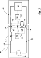
- FIG Figure 2 shows, in a further development, a further electrical supply system 1.1.
- This is constructed in principle like the electrical supply system 1 of the exemplary embodiment in FIG Figure 1 .
- the same components of this electrical supply system 1.1 with those of the electrical supply system 1 are identical Reference symbols identified, supplemented by the suffix ".1" or a correspondingly higher counter.
- the electrical supply system 1.1 has data transmission contacts 11, 11.1, one data transmission contact 11 being assigned to the converter 3.1 and a data transmission contact 11.1 being assigned to the consumer module 5.1.
- the transducer-side data transmission contact 11 is connected to a control unit 10, designed as a microcontroller in the illustrated embodiment.
- the consumer module 5.1 also has a control unit 10.1 by which the electrical consumer 4.1 is controlled. Via the data line connecting the two control units 10, 10.1, data for controlling the consumer 4.1 of the consumer module 5.1 can be transmitted, for example dimming data.
- the converter-side control unit 10 is used so that an actuation signal from the sensor 9.1 is applied to a sensor input of the control unit 10. The sensor signal generated when the sensor 9.1 is actuated is evaluated by the control unit 10, which then controls the switching element 8.1 accordingly as a function of the sensor signal received.
- the switching element 8.1 is closed in order to enable the power supply to the consumer module 5.1 in this way .
- Figure 3 shows another electrical supply system 1.2, which is basically constructed like the electrical supply system 1.1, the sensor of which, however, works exclusively electrically.
- the converter 3.2 comprises a voltage divider 12 as a sensor, which is formed from two resistors 13, 13.1 connected in series.
- the input 14 of the voltage divider 12 is on supply line 6.4 and its output 15 on the Supply line 6.5 and thus connected to the constant voltage supply.
- the node 16 located between the resistors 13, 13.1 is connected to a data transmission contact 11.2 and also to the converter-side control unit 10.2.
- the consumer module 5.2 of this electrical supply system 1.2 also has a voltage divider 17 with two resistors 18, 18.1 connected in series.
- the voltage divider 17 on the consumer module side is connected with its input 19 and with its output 20 to its voltage supply contacts 7.10, 7.11 or to the lines connected thereto.
- a node 21 located between the resistors 18, 18.1 is connected to the data transmission contact 11.3 assigned to the consumer module 5.2.
- the voltage divider 12 on the conversion side has a different division ratio than the voltage divider 17 on the consumer module side.
- the consumer module 5.2 is connected to the interface 2.2 of the converter 3.2, when the test voltage is applied to the supply lines 6.4, 6.5, the voltage that can be tapped in the converter-side node 16 is passed through the connection of the node 21 of the consumer module-side voltage divider 17 via the interconnected data transmission contacts 11.2, 11.3 influenced.
- the electrical supply system 1.2 according to Figure 3 at least one resistor 22 between the nodes 16, 21 of the voltage dividers 12, 17 on the converter or consumer module side.
- the current made available at the node 16 is limited and the energy consumption is limited to a safe level.
- the consumer module 5.2 has several LEDs as a consumer 4.2.
- the control unit 10.2 compares the measured voltage value provided by the sensor used as the voltage divider 12 with a target value range.
- the target value range is between 5.0V and 6.2V.
- the converter-side voltage divider 12 is designed so that a voltage of 7.8V can be tapped off at its junction point 16, if no counterpart on the consumer module side influencing the voltage at junction point 16 is connected to the interface 2.2.
- the voltage divider 17 on the consumer module side whose node 21 is then connected to the converter-side node 16, reduces the voltage that can be tapped at the node 16 to 5.6V .
- the above-described target value range has been defined as a comparison variable in this exemplary embodiment.
- the converter 3.2 has a detection sensor system which is used to detect when a consumer module 5.2 is connected to the interface 2.2.
- the test voltage is applied to the supply lines 6.4, 6.5 at the interface 2.2 of the converter 3.2.
- This can - as in Figure 3 shown - for example by a bypass 23, through which the switching element 8.2 connected to a supply line 6.4 is bridged, can be realized.
- the test voltage is designed to be lower than the supply voltage, but in any case the test voltage is only characterized by an extremely low load capacity, so that it cannot cause any dangerous conditions.
- a high-resistance resistor 24 or a current limiter and a switching element 25 controllable by the control unit 10.2 of the converter 3.2 are switched on in the bypass 23.
- the voltage provided by the voltage supply S.2 is considerably reduced by the high-resistance resistor 24 for carrying out the admissibility check, so that the test voltage is not critical for the consumer module 5.2 as well as for a person or imported materials who may come to the voltage supply contacts 7.8, 7.9 is.
- the detection of a permissible consumer module is also to be recorded here, as described above, via the voltage change due to the action of the voltage divider 17 at the node 16.
- the consumer module 5.2 has a control unit which is connected to the data transmission contact 11.3 on the consumer module side. For the sake of clarity, this control unit is not shown in the figure. This control unit is used to control the electrical consumer 4.2.
- the data connection provided via the data transmission contacts 11.2, 11.3 between the converter 3.2 and the consumer module 5.2 is also used to transmit data when the consumer module 5.2 is in operation.
- the electrical supply system 1.2 can also be operated in such a way that an identification code is transmitted from the consumer module 5.2 to the converter 3.2 or its control unit 10.2 via the data connection described.
- the Control unit 10.2 represents the detection sensor if the to the embodiment of the Figure 3 described voltage dividers 12, 17 are not available or are not used for the consumer module coding.
- Figure 4 shows a further embodiment of an electrical supply system 1.3.
- this is structured similarly to that of Figure 3 described electrical supply system 1.2.
- the converter-side voltage divider 12.1 is located between the electrical supply lines 6.6, 6.7 in front of the switching element 8.3 connected to the supply line 6.6.
- the same components as in the previous exemplary embodiments are provided with the same reference numerals, supplemented by a suffix which is one counter larger than in the previous exemplary embodiment.
- only a small test current can be conducted via the data transmission contact 11.4 when the switching element 8.3 is open.
- the data transmission contact 11.1 is connected to the electrical supply line 6.6 via a line.
- the high-resistance resistor 22.1 is switched on in this line, so that only a small current can flow via the data transmission contact 11.4.
- the control unit 10.4 can detect a voltage due to its connection to the node 16.1 and its connection to the ground line - the electrical supply line 6.7. In order to make this possible, it is not absolutely necessary for the resistor 13.3 to be switched on in the line branch connecting the electrical supply line 6.7 to the node 16.1.
- the resistor 18.3 of its voltage divider 17.1 is basically required. After all, it is up to the converter side Voltage supply contact 7.12 no voltage due to the open switching element 8.3. If the consumer module 5.3 is connected to the converter 3.3, an electrical connection is established between the converter-side data transfer contact 11.4 and its voltage supply contact 7.13 via the resistor 18.3.
- the resistor 18.3 causes a voltage drop, so that the control unit 10.4, after the consumer module 5.3 has been connected to the converter 3.3, detects a voltage drop compared to the voltage otherwise present at the data transmission contact 11.4.
- the level of the voltage drop or the voltage measured by the control unit 10.4 on the basis of the resistor 18.3 is used as coding for the consumer module 5.3. If the voltage detected by the control unit 10.4 corresponds to the predefined voltage, the control unit 10.4 controls the switching element 8.3 to close the same.
- both the converter 3.3 and the electrical consumer module 5.3 each have a voltage divider 12.1 and 17.1, a second control can be carried out over the voltage dividers 12.1, 17.1 in this embodiment, in a manner analogous to this the embodiment of Figure 3 is described. In this way, a redundant check of the consumer module 5.3 connected to the converter 3.3 can be carried out.
Landscapes
- Engineering & Computer Science (AREA)
- Power Engineering (AREA)
- Physics & Mathematics (AREA)
- General Physics & Mathematics (AREA)
- Arrangements For Transmission Of Measured Signals (AREA)
- Remote Monitoring And Control Of Power-Distribution Networks (AREA)
Abstract
Ein elektrisches Versorgungssystem 1 umfasst einen eine mechanische und eine elektrische Schnittstelle 2 aufweisenden Wandler 3. Der Wandler 3 dient zum Bereitstellen einer Konstantspannungsversorgung. Das elektrische Versorgungssystem 1 umfasst desweiteren ein zumindest einen elektrischen Verbraucher 4 aufweisendes Verbrauchermodul 5. Der Wandler 3 und das Verbrauchermodul 5 verfügen über einen ersten und einen zweiten Spannungsversorgungkontakt 7 - 7.3, welche verbrauchermodulseitigen Spannungsversorgungskontakte 7.2, 7.3 mit denjenigen des Wandlers 3 lösbar verbindbar sind und welche wandlerseitigen Spannungsversorgungskontakte 7, 7.1 an eine Versorgungsleitung 6, 6.1 angeschlossen sind. Wandlerseitig ist in zumindest eine der beiden Versorgungsleitungen 6, 6.1 ein im nicht betätigten Zustand in Offen-Stellung befindliches Schaltelement 8 eingeschaltet. Der Wandler 3 verfügt über einen Sensor 9 zum Detektieren, ob ein für einen Betrieb mit diesem Wandler 3 zulässiges Verbrauchermodul 5 bestimmungsgemäß an seine Schnittstelle 2 angeschlossen ist, wobei der Sensor 9 bei einem bestimmungsgemäß an den Wandler 3 angeschlossenen, zulässigen Verbrauchermodul 5 mittel- oder unmittelbar das zumindest eine Schaltelement 8 in seine Geschlossen-Stellung bringt.Beschrieben ist des Weiteren ein Verfahren zum Betreiben eines solchen elektrischen Versorgungssystems 1.An electrical supply system 1 comprises a converter 3 having a mechanical and an electrical interface 2. The converter 3 is used to provide a constant voltage supply. The electrical supply system 1 further comprises a consumer module 5 having at least one electrical consumer 4. The converter 3 and the consumer module 5 have a first and a second voltage supply contact 7 - 7.3, which consumer module-side voltage supply contacts 7.2, 7.3 can be detachably connected to those of the converter 3 and which converter-side voltage supply contacts 7, 7.1 are connected to a supply line 6, 6.1. On the converter side, a switching element 8, which is in the open position in the non-actuated state, is switched on in at least one of the two supply lines 6, 6.1. The converter 3 has a sensor 9 for detecting whether a consumer module 5 that is permitted for operation with this converter 3 is properly connected to its interface 2, with the sensor 9 being medium or medium-sized with a permitted consumer module 5 connected to the converter 3 as intended directly brings the at least one switching element 8 into its closed position. A method for operating such an electrical supply system 1 is also described.
Description
Die Erfindung betrifft ein elektrisches Versorgungssystem mit einem eine mechanische und eine elektrische Schnittstelle aufweisenden Wandler zum Bereitstellen einer Konstantspannungsversorgung und mit einem daran anschließbaren, zumindest einen elektrischen Verbraucher aufweisenden Verbrauchermodul, wobei der Wandler und das Verbrauchermodul einen ersten und einen zweiten Spannungsversorgungkontakt umfassen, welche verbrauchermodulseitigen Spannungsversorgungskontakte des Verbrauchermoduls mit denjenigen des Wandlers lösbar verbindbar sind und welche wandlerseitigen Spannungsversorgungskontakte an eine Versorgungsleitung angeschlossen sind. Ferner betrifft die Erfindung ein Verfahren zum Betreiben eines solchen elektrischen Versorgungssystems.The invention relates to an electrical supply system with a converter having a mechanical and an electrical interface for providing a constant voltage supply and with a consumer module that can be connected to it and has at least one electrical consumer, the converter and the consumer module comprising a first and a second voltage supply contact, which consumer module-side voltage supply contacts of the consumer module can be detachably connected to those of the converter and which converter-side voltage supply contacts are connected to a supply line. The invention also relates to a method for operating such an electrical supply system.
Die elektrische Energieversorgung von nicht fest installierten elektrischen Verbrauchern erfolgt typischerweise über den Anschluss eines elektrischen Verbrauchers an eine an das öffentliche Stromversorgungsnetz angeschlossene Steckdose als elektrische und mechanische Schnittstelle zwischen dem Stromversorgungsnetz und einem daran anzuschließenden elektrischen Verbraucher. Andere Stromversorgungssysteme dienen zur Stromversorgung von elektrischen Verbrauchern und liefern an ihren diesbezüglichen Schnittstellen eine Konstantspannung, beispielsweise 12V oder 24V. Eingesetzt werden hierfür Wandler, die die 230V-Wechselspannung des öffentlichen Netzes in die für den Betrieb eines spezifischen elektrischen Verbrauchers benötigte Niedervolt-Gleichspannung wandeln. Aus Sicherheitsgründen sind bei derartigen Wandlern Mechanismen vorgesehen, die einen Betrieb des Wandlers ausschließlich im Bereich eines bestimmten Spannungs-Strom-Bereiches zulassen. Zu diesem Zweck werden spezielle Arbeitspunkte definiert, um einen hinreichenden Schutz vor Überlastung des Wandlers zu gewährleisten. Dieses betrifft nicht lediglich die mittlere Leistungsaufnahme durch den an den Wandler angeschlossenen Verbraucher, sondern auch die Leistungsaufnahme während eines Schaltvorganges, weshalb auch zeitabhängige Bereiche definiert werden, um etwa Durchbruchseffekte in Transistoren zu vermeiden. Durch diese Maßnahmen wird grundsätzlich ein hinreichender Schutz vor einem elektrischen Fehlbetrieb des Wandlers erreicht. Nicht unproblematisch ist mitunter ein Betriebsfall, der zwar aus elektrischer Sicht unbedenklich ist, also in dem zugelassenen Spannungs-Strom-Bereich liegt, der aber durch die Art der an den Wandler angeschlossenen Last dennoch einen Fehllastbetrieb darstellt. Eine derartige Betriebssituation könnte durch Einführen von elektrisch leitenden Gebrauchsutensilien, wie etwa Essbesteck, Nadeln oder Kinderspielzeug in die elektrische Schnittstelle des Wandlers, beispielsweise durch Kinder entstehen. Eine solche Betriebssituation kann sich auch einstellen, wenn die Schnittstelle des Wandlers mit metallischer Scheuerwolle gereinigt wird und hierbei der stromführende Versorgungsspannungskontakt des Wandlers kontaktiert wird.The electrical energy supply of electrical consumers that are not permanently installed is typically carried out by connecting an electrical consumer to a socket connected to the public power supply network as an electrical and mechanical interface between the power supply network and an electrical consumer to be connected to it. Other power supply systems are used to supply power to electrical consumers and provide a constant voltage, for example 12V or 24V, at their interfaces. Converters are used for this purpose, which convert the 230V alternating voltage of the public grid into the low-voltage direct voltage required for the operation of a specific electrical consumer. For safety reasons, mechanisms are provided in converters of this type which allow the converter to be operated exclusively in the range of a specific voltage-current range. For this purpose, special operating points are defined to ensure adequate protection against overloading the converter. This not only affects the average power consumption by the consumer connected to the converter, but also the power consumption during one Switching process, which is why time-dependent areas are defined in order to avoid breakdown effects in transistors. These measures basically provide adequate protection against electrical malfunction of the converter. Occasionally, an operating case that is harmless from an electrical point of view, i.e. lies in the permitted voltage-current range, but which nevertheless represents a faulty load operation due to the type of load connected to the converter is not unproblematic. Such an operating situation could arise through the introduction of electrically conductive utensils such as cutlery, needles or children's toys into the electrical interface of the transducer, for example by children. Such an operating situation can also arise if the interface of the converter is cleaned with metallic scouring wool and the current-carrying supply voltage contact of the converter is contacted.
Aus dem Stand der Technik sind zur Sicherung von Steckdosen als Spannungsversorgungsschnittstellen gegen unsachgemäßen Betrieb durch Kinder mechanische Kindersicherungen bekannt, bei denen die Steckdose entweder durch Abdeckklappen gesichert ist oder - im Falle von offenen Steckdosen - die Spannungskontakte durch mechanische Verriegelungsmechanismen, die es zur Nutzung der Schnittstelle erst zu überwinden gilt, blockiert sind. Derartige Sicherungen sind verbreitet, jedoch mitunter schwierig bzw. umständlich zu betätigen. Eine Überwindung des Verriegelungsmechanismus erfolgt mit den Steckkontakten eines Steckers, beispielsweise dadurch, dass die eine die Einstecköffnung verblendende Sicherungsscheibe in ihre Freigabestellung gedreht werden muss, bevor die Steckkontakte mit den komplementären Steckbuchsenkontakten der Steckdose in Eingriff gestellt werden können.From the prior art, mechanical child safety devices are known for securing sockets as voltage supply interfaces against improper operation by children, in which the socket is either secured by cover flaps or - in the case of open sockets - the voltage contacts by mechanical locking mechanisms that allow the use of the interface only to be overcome are blocked. Such fuses are common, but sometimes difficult or awkward to operate. The locking mechanism is overcome with the plug contacts of a plug, for example in that the one locking washer facing the plug-in opening has to be rotated into its release position before the plug contacts can be engaged with the complementary socket contacts of the socket.
Auch sind über eine Fernbedienung betätigbare Wandler und Steckdosen bekannt, bei denen die elektrische Versorgung des angeschlossenen Verbrauchers erst dann freigegeben wird, wenn nutzerseitig ein entsprechender Befehl abgesetzt worden ist. Eine hinreichende Sicherung zur Vermeidung von den vorbeschriebenen unzulässigen Betriebssituationen kann, da die Anschlusskontakte zugänglich sind, nicht wirksam vermieden werden. Hierzu bedürfte es eines zusätzlichen Einsatzes einer mechanischen Sicherung, beispielsweise wie vorbeschrieben.Converters and sockets that can be operated via remote control are also known in which the electrical supply of the connected consumer is only released when a corresponding command has been issued by the user. A sufficient safeguard to avoid the above-described inadmissible operating situations cannot, since the connection contacts are accessible effectively avoided. This would require an additional use of a mechanical safety device, for example as described above.
Ausgehend von dem diskutierten Stand der Technik liegt der Erfindung daher die Aufgabe zu Grunde, ein elektrisches Versorgungssystem mit einem Wandler und mit einem daran lösbar anschließbaren Verbrauchermodul bereitzustellen, bei dem gewährleistet ist, dass sich auch die vorbeschriebenen, nicht zulässigen Betriebssituationen nicht einstellen können.Based on the discussed prior art, the invention is therefore based on the object of providing an electrical supply system with a converter and with a consumer module that can be detachably connected to it, in which it is ensured that the above-described, non-permissible operating situations cannot arise.
Diese Aufgabe wird erfindungsgemäß durch ein eingangs genanntes elektrisches Versorgungssystem gelöst, bei dem wandlerseitig in zumindest eine der beiden Versorgungsleitungen ein im nicht betätigten Zustand in Offen-Stellung befindliches Schaltelement eingeschaltet ist und der Wandler über einen Sensor zum Detektieren verfügt, ob ein für einen Betrieb mit diesem Wandler zulässiges Verbrauchermodul bestimmungsgemäß an seine Schnittstelle angeschlossen ist, wobei der Sensor bei einem bestimmungsgemäß an den Wandler angeschlossenen, zulässigen Verbrauchermodul mittel- oder unmittelbar das zumindest eine Schaltelement in seine Geschlossen-Stellung bringt.According to the invention, this object is achieved by an electrical supply system mentioned at the beginning, in which a switching element that is in the open position in the non-actuated state is switched on at the converter side in at least one of the two supply lines and the converter has a sensor for detecting whether a switch is required for operation with This converter permissible consumer module is intended to be connected to its interface, the sensor directly or indirectly bringing the at least one switching element into its closed position when a permissible consumer module is properly connected to the converter.
Bei diesem elektrischen Versorgungssystem wird das elektrische Verbrauchermodul mit seinem zumindest einen elektrischen Verbraucher durch einen Wandler, der über eine Gleichspannungsquelle - beispielsweise eine Batterie oder eine gleichgerichtete Wechselspannung - verfügt, mit Konstantspannung versorgt. Der Wandler weist eine Schnittstelle auf, an die das Verbrauchermodul anzuschließen bzw. angeschlossen ist. Der Anschluss des Verbrauchermoduls ist lösbar ausgelegt, damit unterschiedliche Verbrauchermodule an die Schnittstelle angeschlossen werden können. Zum Betrieb des über die Schnittstelle an den Wandler angeschlossenen Verbrauchermoduls ist dieses durch den Wandler konstantspannungsversorgt. Die beiden Versorgungsleitungen des Wandlers sind an eine Stromversorgung angeschlossen. In wenigstens eine dieser beiden Versorgungsleitungen ist ein Schaltelement eingeschaltet. Dieses befindet sich, wenn nicht betätigt, in seiner Offen-Stellung. Damit ist die Schnittstelle des elektrischen Versorgungssystems grundsätzlich spannungslos. Geschaltet wird das zumindest eine Schaltelement unmittelbar durch oder mittelbar über einen dem Wandler zugehörigen Sensor. Dieser dient zum Detektieren, ob ein für einen Betrieb mit diesem Wandler zulässiges Verbrauchermodul bestimmungsgemäß an die Schnittstelle des Wandlers angeschlossen ist. Der Sensor detektiert somit, ob es sich bei dem angeschlossenen Verbrauchermodul mit seinem einen oder mehreren Verbrauchern um ein zum Anschluss an den Wandler zulässiges Verbrauchermodul handelt und ob dieses bestimmungsgemäß an den Wandler angeschlossen ist. In Abhängigkeit von dem Detektionsergebnis des Sensors und zwar dann, wenn der Sensor den bestimmungsgemäßen Anschluss eines zugelassenen Verbrauchermoduls detektiert hat, bringt dieser das zumindest eine Schaltelement in seine Geschlossen-Stellung und stellt damit die Konstantspannungsversorgung des Verbrauchermoduls mit seinem zumindest einen elektrischen Verbraucher her. Anderenfalls verbleibt das in die zumindest eine der beiden Versorgungsleitungen eingeschaltete Schaltelement in seiner Offen-Stellung. Der Stromfluss zu dem an diese Versorgungsleitung angeschlossenen Spannungsversorgungskontakt bleibt damit unterbunden. Das Schaltelement wird man typischerweise in die stromführende Versorgungsleitung einschalten. Durch diese Maßnahme liegt an dem an diese Versorgungsleitung angeschlossenen Spannungsversorgungskontakt nur dann Spannung an, wenn durch das an den Wandler mechanisch angeschlossene Verbrauchermodul bestimmungsgemäß montiert und damit auch die Spannungsversorgungskontakte nicht mehr zugänglich sind. Eine unsachgemäße Betriebssituation, wie beispielsweise durch Einführen von elektrisch leitenden Gebrauchs- oder Spielutensilien in eine Steckeraufnahme, sollte eine derartige vorgesehen sein, oder die Berührung eines freiliegenden Spannungsversorgungskontaktes, da stromlos, stellt bei diesem Wandler keine Gefährdung dar. Strom- bzw. spannungsbeaufschlagt sind die Spannungsversorgungskontakte nur, wenn ein zulässiges Verbrauchermodul bestimmungsgemäß an den Wandler angeschlossen ist.In this electrical supply system, the electrical consumer module with its at least one electrical consumer is supplied with constant voltage by a converter which has a direct voltage source - for example a battery or a rectified alternating voltage. The converter has an interface to which the consumer module is to be connected or connected. The connection of the consumer module is designed to be detachable so that different consumer modules can be connected to the interface. To operate the consumer module connected to the converter via the interface, it is supplied with constant voltage by the converter. The two supply lines of the converter are connected to a power supply. A switching element is switched on in at least one of these two supply lines. When not activated, this is in its open position. This means that the interface of the electrical supply system is basically dead. The at least one switching element is switched directly by or indirectly via a sensor associated with the converter. This is used to detect whether a consumer module that is permissible for operation with this converter is properly connected to the converter interface. The sensor thus detects whether the connected consumer module with its one or more consumers is a consumer module that is permissible for connection to the converter and whether this is connected to the converter as intended. Depending on the detection result of the sensor, namely when the sensor has detected the intended connection of an approved consumer module, it brings the at least one switching element into its closed position and thus produces the constant voltage supply of the consumer module with its at least one electrical consumer. Otherwise, the switching element switched into the at least one of the two supply lines remains in its open position. The current flow to the voltage supply contact connected to this supply line is thus prevented. The switching element will typically be switched into the live supply line. As a result of this measure, voltage is only applied to the voltage supply contact connected to this supply line when the consumer module mechanically connected to the converter has been installed as intended and the voltage supply contacts are no longer accessible. An improper operating situation, for example by inserting electrically conductive utensils or play utensils into a plug receptacle, should be provided, or touching an exposed voltage supply contact, since it is de-energized, does not pose a risk with this converter Power supply contacts only if a permitted consumer module is properly connected to the converter.
Der Sensor zum Detektieren eines bestimmungsgemäßen Anschlusses eines zulässigen Verbrauchermoduls an den Wandler kann unterschiedlich arbeitend ausgelegt sein. Die Kodierung für die Detektion zwischen Wandler und Verbrauchermodul kann beispielsweise mechanisch, magnetisch, mittels RFID optisch oder auch elektrisch ausgelegt sein. Auch eine Kombination von verschiedenen Maßnahmen ist möglich.The sensor for detecting an intended connection of a permissible consumer module to the converter can be designed to work in different ways. The coding for the detection between the converter and the consumer module can for example be designed mechanically, magnetically, optically by means of RFID or also electrically. A combination of different measures is also possible.
Im Falle einer mechanischen Kodierung einer Sensorbetätigung ist gemäß einer Ausgestaltung der Sensor als Tastsensor ausgelegt und im Bereich der Schnittstelle des Wandlers derart angeordnet, dass dieser sich nicht ohne Weiteres betätigen lässt. Eine andere Art der Kodierung einer bestimmungsgemäßen Sensorbetätigung kann magnetisch erfolgen. Der Sensor wird bei einer solchen Auslegung dann durch einen dem Verbrauchermodul zugeordneten Betätigungsmagneten betätigt. Eine solche Sensorbetätigung kann durch die abstoßende Kraft zweier Magnete oder durch eine Anzugskraft zweier Magnete oder auch durch einen Magneten hervorgerufen werden. Wird nur ein Magnet eingesetzt, handelt es sich bei dem Gegenstück um ein Bauteil mit ferromagnetischen Eigenschaften. Der Betätigungsmagnet wird typischerweise dem Verbrauchermodul zugeordnet sein, damit eine Sensorbetätigung nicht bereits dann erfolgt, wenn an die Schnittstelle ein ferromagnetisches Metallstück gehalten wird.In the case of a mechanical coding of a sensor actuation, according to one embodiment, the sensor is designed as a touch sensor and is arranged in the area of the interface of the converter in such a way that it cannot be easily actuated. Another type of coding of an intended sensor actuation can be done magnetically. With such a design, the sensor is then actuated by an actuating magnet assigned to the consumer module. Such a sensor actuation can be caused by the repulsive force of two magnets or by an attraction force of two magnets or also by a magnet. If only one magnet is used, the counterpart is a component with ferromagnetic properties. The actuation magnet is typically assigned to the consumer module so that the sensor does not already take place when a ferromagnetic metal piece is held at the interface.
Eine optische Kodierung kann beispielsweise durch das Lesen eines auf dem Verbrauchermodul befindlichen Barcodes durch den Sensor realisiert sein. Ebenfalls ist eine optische Kodierung möglich, bei der das Verbrauchermodul Licht einer bestimmten Wellenlänge aussendet oder reflektiert, welches durch den Sensor erfasst wird und das Schaltelement nur für den Fall einer von dem Sensor empfangenen zugelassenen Wellenlänge in seine Geschlossen-Stellung gebracht wird.Optical coding can be implemented, for example, by reading a bar code on the consumer module by the sensor. Optical coding is also possible in which the consumer module emits or reflects light of a certain wavelength, which is detected by the sensor and the switching element is only brought into its closed position in the event of an approved wavelength received by the sensor.
Bei dem Sensor kann es sich um das bewegliche Teil des in die Stromversorgungsleitung eingeschalteten Schaltelementes handeln. Dann erfolgt ein Schalten dieser Versorgungsleitung unmittelbar durch den Sensor, und zwar ohne Zwischenschaltung einer Steuereinheit, etwa eines Microcontrollers. Gemäß einer anderen Ausgestaltung ist der Sensor an einen Auswerteeingang einer Steuereinheit angeschlossen, die das Sensorsignal auswertet und in Abhängigkeit von dem empfangenen Sensorsignal das Schaltelement entsprechend ansteuert, wenn sich aus dem empfangenen Sensorsignal ergibt, dass das in die Versorgungsleitung eingeschaltete Schaltelement geschlossen werden soll. Das Sensorsignal kann das Signal eines geschlossenen Tasters sein. Ist eine Steuereinheit an einen solchen Sensor angeschlossen, kann die Einschaltinformation auch durch eine bestimmte Sensorbetätigungsfolge kodiert sein.The sensor can be the moving part of the switching element connected to the power supply line. This supply line is then switched directly by the sensor, without the interposition of a control unit, for example a microcontroller. According to another embodiment, the sensor is connected to an evaluation input of a control unit, which evaluates the sensor signal and, depending on the received sensor signal, controls the switching element accordingly if the received sensor signal shows that the switching element connected to the supply line is to be closed. The sensor signal can be the signal of a closed button. If a control unit is connected to such a sensor, the switch-on information can also be coded by a specific sensor actuation sequence.
In aller Regel ist in einem solchen Wandler für den Betrieb des Verbrauchermoduls ohnehin eine als Microcontroller ausgelegte Steuereinheit vorhanden, sodass dessen Ressourcen ohne Weiteres auch für die Realisierung dieses Konzeptes genutzt werden können.As a rule, a control unit designed as a microcontroller is already present in such a converter for operating the consumer module, so that its resources can also be used without further ado for the implementation of this concept.
In einer Ausführungsform der Erfindung ist die mechanische Schnittstelle des Wandlers als mechanische Aufnahme nach Art einer Steckdose ausgeführt, in die ein komplementäres, für einen Betrieb mit dem Wandler zulässiges Verbrauchermodul den Sensor betätigendes Gegenstück einzusetzen ist.In one embodiment of the invention, the mechanical interface of the transducer is designed as a mechanical receptacle in the manner of a socket, into which a complementary consumer module which is permissible for operation with the transducer and actuates the sensor is to be inserted.
Zahlreiche elektrische Versorgungssysteme der in Rede stehenden Art verfügen neben den beiden Spannungsversorgungskontakten zusätzlich über einen Datenübertragungskontakt. Der wandlerseitige Datenübertragungskontakt ist an seine Steuereinheit angeschlossen. Über den Datenübertragungskontakt werden Ansteuerdaten an das Verbrauchermodul übermittelt. Eine solche Datenübertragung kann unidirektional oder auch bidirektional erfolgen. Das Vorhandensein des zusätzlichen Datenkontaktes an der elektrischen Schnittstelle zwischen Wandler und Verbrauchermodul eröffnet die Möglichkeit, auf besonders einfache Weise auch eine elektrische Kodierung bereitzustellen. In einer möglichen Ausführungsform ist zu diesem Zweck der wandlerseitige Datenkontakt an die erste Versorgungsleitung angeschlossen, und zwar unter Einschaltung eines hochohmigen Widerstandes. An einem Knotenpunkt dieser Verbindungsleitung ist die Steuereinheit angeschlossen, wobei der hochohmige Widerstand zwischen diesem Knotenpunkt, an dem die Steuereinheit angeschlossen ist, und dem Datenkontakt vorgesehen ist. In dem ersten Abschnitt dieser Verbindungsleitung, der den Abzweig von der Versorgungsleitung mit dem genannten Knotenpunkt verbindet, ist ebenfalls ein Widerstand eingeschaltet. Der Abzweig dieser Verbindungsleitung befindet sich - von der Spannungsquelle aus betrachtet - vor dem von der Steuereinheit ansteuerbaren Schaltelement. Auf diese Weise kann über den Datenkontakt nur ein geringer Strom geführt werden. Der vorbeschriebene Knotenpunkt hat ebenfalls eine Verbindung zur Masseleitung, wobei in diesen Leitungsabschnitt vorzugweise ebenfalls ein Widerstand eingeschaltet ist. Wenn der Datenkontakt des Wandlers mit seinem zweiten Spannungsversorgungskontakt - dem Massekontakt - verbunden ist, kann die Steuereinheit über den Knotenpunkt die anliegende Spannung erfassen.Numerous electrical supply systems of the type in question also have a data transmission contact in addition to the two voltage supply contacts. The converter-side data transmission contact is connected to its control unit. Control data are transmitted to the consumer module via the data transmission contact. Such data transmission can take place unidirectionally or also bidirectionally. The presence of the additional data contact at the electrical interface between converter and consumer module opens up the possibility of also providing electrical coding in a particularly simple manner. In one possible embodiment, the data contact on the converter side is connected to the first supply line for this purpose, with the inclusion of a high-value resistor. The control unit is at a junction of this connecting line connected, the high-resistance resistor between this node, to which the control unit is connected, and the data contact is provided. A resistor is also switched on in the first section of this connection line, which connects the branch from the supply line to the aforementioned node. The branch of this connecting line is - viewed from the voltage source - in front of the switching element that can be controlled by the control unit. In this way, only a small amount of current can be carried through the data contact. The node described above also has a connection to the ground line, a resistor preferably also being switched on in this line section. If the data contact of the converter is connected to its second voltage supply contact - the ground contact - the control unit can detect the applied voltage via the node.
Als Komplementär verfügt das Verbrauchermodul über einen seinen Datenkontakt mit seinem Massekontakt verbindenden Widerstand, durch den ein spezifischer Spannungsabfall herbeigeführt wird. Die Größe des Widerstandes und der dadurch bewirkte Spannungsabfall bei an dem Wandler angeschlossenen Verbrauchermodul in dem Knotenpunkt des Wandlers, an den die Steuereinheit angeschlossen ist, stellt somit eine Kodierung desselben dar. Ist das Verbrauchermodul an den Wandler angeschlossen, wird dieser Spannungsabfall durch die an den Knotenpunkt angeschlossene Steuereinheit erfasst. Entspricht der Spannungsabfall dem für ein zulässiges Verbrauchermodul vorgesehenen Spannungsabfall wird durch die Steuereinheit das in die Versorgungsleitung eingeschaltete Schaltelement in seine Geschlossen-Stellung gebracht.As a complement, the consumer module has a resistor that connects its data contact with its ground contact, through which a specific voltage drop is brought about. The size of the resistance and the resulting voltage drop in the consumer module connected to the converter in the node of the converter to which the control unit is connected thus represents a coding of the same. If the consumer module is connected to the converter, this voltage drop is caused by the Control unit connected to the node detected. If the voltage drop corresponds to the voltage drop provided for a permissible consumer module, the control unit moves the switching element connected to the supply line into its closed position.
Gemäß einem weiteren Ausführungsbeispiel einer Spannungskodierung des Wandlermoduls dient wandlerseitig ein Spannungsteiler als Sensor. Dieser ist durch zumindest zwei in Reihe geschaltete Widerstände gebildet. Der Spannungsteiler ist zwischen den Versorgungsleitungen des Wandlers aufgespannt und befindet sich vor dem, die Versorgungsspannung an die Schnittstelle schaltenden Schaltelement, sodass dieses auch bei geöffnetem Schaltelement bestromt ist. Dabei ist der Eingang des Spannungsteilers an einen ersten Spannungsversorgungskontakt bzw. die an diesen Spannungsversorgungskontakt angeschlossene Versorgungsleitung und der Ausgang an den zweiten Spannungsversorgungskontakt bzw. die an diesen Spannungsversorgungskontakt angeschlossene Versorgungsleitung angeschlossen. An einen zwischen den Widerständen des Spannungsteilers befindlichen Knotenpunkt ist der Datenübertragungskontakt angeschlossen. Dieser Knotenpunkt ist zugleich an einen Sensoreingang der Steuereinheit des Wandlers angeschlossen. Bei diesem elektrischen Verbrauchersystem verfügt auch das Verbrauchermodul über einen Spannungsteiler mit zumindest zwei in Reihe geschalteten Widerständen. Dieser ist ebenfalls zwischen den beiden Spannungsversorgungskontakten aufgespannt. Auch zwischen den Widerständen dieses Spannungsteilers befindet sich ein Knotenpunkt, der an den Datenübertragungskontakt des Verbrauchermoduls gelegt ist. Die beiden Spannungsteiler sind unterschiedlich aufgebaut, sodass die in dem jeweiligen Knotenpunkt abgegriffene Spannung sich voneinander unterscheidet. Durch die Auslegung der Spannungsteiler erfolgt bei dieser Realisierung die Kodierung zwischen Wandler und Verbrauchermodul. Nur wenn am wandlerseitigen Knotenpunkt und damit am sensorseitigen Eingang der Steuereinheit eine vorbestimmte Spannung bei angeschlossenem Verbrauchermodul abgegriffen wird, wird durch die Steuereinheit das in die Versorgungsleitung eingeschaltete Schaltelement entsprechend angesteuert. Hierzu werden bei diesem Ausführungsbeispiel die Spannungsteiler des Wandlers und des Verbrauchermoduls mit einer Testspannung, die geringer als die Versorgungsspannung ist und lediglich einen geringen Stromfluss verursacht, beaufschlagt. Die Möglichkeiten einer solchen Kodierung sind vielfältig. Grundlage der Auswertung ist, dass durch ein zulässiges und bestimmungsgemäß an den Wandler angeschlossenes Verbrauchermodul die am wandlerseitigen Knotenpunkt abgegriffene Spannung sich von derjenigen unterscheidet, die an diesem Knotenpunkt abgreifbar ist, wenn an die Schnittstelle des Wandlers kein Verbrauchermodul angeschlossen ist. Beeinflusst wird die an dem wandlerseitigen Knotenpunkt abgreifbare Spannung durch den auf diesen Knotenpunkt ebenfalls Einfluss nehmenden Spannungsteiler des Verbrauchermoduls, da über die miteinander in Kontakt stehenden Datenübertragungskontakte der Knotenpunkt des verbrauchermodulseitigen Spannungsteilers auf den Knotenpunkt des wandlerseitigen Spannungsteiler gelegt ist.According to a further exemplary embodiment of a voltage coding of the converter module, a voltage divider serves as a sensor on the converter side. This is formed by at least two resistors connected in series. The voltage divider is set up between the supply lines of the converter and is located in front of the switching element that switches the supply voltage to the interface, so that it is energized even when the switching element is open. The input of the voltage divider is connected to a first voltage supply contact or the supply line connected to this voltage supply contact, and the output is connected to the second voltage supply contact or the supply line connected to this voltage supply contact. The data transmission contact is connected to a node located between the resistors of the voltage divider. This node is also connected to a sensor input of the converter control unit. In this electrical consumer system, the consumer module also has a voltage divider with at least two resistors connected in series. This is also stretched between the two power supply contacts. There is also a node between the resistors of this voltage divider, which is connected to the data transmission contact of the consumer module. The two voltage dividers are designed differently, so that the voltages tapped at the respective node differ from one another. Due to the design of the voltage divider, the coding between the converter and the consumer module takes place in this implementation. Only when a predetermined voltage is tapped at the transducer-side node and thus at the sensor-side input of the control unit when the consumer module is connected, the control unit actuates the switching element switched on in the supply line accordingly. For this purpose, in this exemplary embodiment, the voltage dividers of the converter and of the consumer module are subjected to a test voltage that is lower than the supply voltage and only causes a low current flow. The possibilities of such a coding are manifold. The evaluation is based on the fact that the voltage tapped at the converter-side node differs from that which can be tapped at this node when no consumer module is connected to the converter interface due to a permissible consumer module connected to the converter as intended. The voltage that can be tapped off at the transducer-side node is influenced by the voltage divider des, which also influences this node Consumer module, since the node of the consumer module-side voltage divider is connected to the node of the converter-side voltage divider via the data transmission contacts that are in contact with one another.
Für die gewünschten Detektionszwecke benötigt man nicht die von dem Wandler zum Betreiben der Verbraucher des Verbrauchermoduls erforderliche Spannung. Vielmehr kann man die vorbeschriebene elektrische Zulässigkeitsprüfung in Bezug auf das an den Wandler angeschlossene Verbrauchermodul bereits bei geringen Spannungen und Strömen durchführen. Dieses kann beispielsweise durch einen Bypass, durch den das in eine Versorgungsleitung eingeschaltete Schaltelement überbrückt wird, realisiert sein. In dem Bypass ist bei einer solchen Ausgestaltung ein hochohmiger Widerstand und ein durch die Steuereinheit des Wandlers ansteuerbares Schaltelement integriert. Für die vorbeschriebene elektrische Zulässigkeitsprüfung wird durch die wandlerseitige Steuereinheit das im Bypass befindliche Schaltelement geschlossen, sodass die durch die Spannungsversorgung bereitgestellte Versorgungsspannung durch den hochohmigen Widerstand erheblich reduziert wird; mithin auf diese Weise eine geringere Testspannung zur Durchführung der Zulässigkeitsprüfung bereitgestellt wird. Die hochohmige Versorgungsspannung am Datenübertragungskontakt ist hinreichend, um die Detektion durchzuführen. Erst wenn die Auswertung der an den wandlerseitigen Knotenpunkt des Spannungsteilers anliegenden Spannung einer zuvor als zulässig definierten Spannung oder innerhalb eines zuvor als zulässig definierten Spannungsbereiches liegt, wird über die Steuereinheit das in die Versorgungsleitung eingeschaltete Schaltelement zum Freigeben der Konstantspannungsversorgung angesteuert.The voltage required by the converter to operate the consumers of the consumer module is not required for the desired detection purposes. Rather, the electrical admissibility test described above with regard to the consumer module connected to the converter can already be carried out at low voltages and currents. This can be implemented, for example, by a bypass through which the switching element connected to a supply line is bypassed. In such a configuration, a high-resistance resistor and a switching element that can be controlled by the control unit of the converter are integrated in the bypass. For the electrical admissibility test described above, the control unit on the converter side closes the switching element located in the bypass, so that the supply voltage made available by the voltage supply is considerably reduced by the high-value resistor; consequently, in this way, a lower test voltage is provided for carrying out the admissibility test. The high-resistance supply voltage at the data transmission contact is sufficient to carry out the detection. Only when the evaluation of the voltage applied to the converter-side node of the voltage divider lies in a voltage previously defined as permissible or within a voltage range previously defined as permissible, the control unit activates the switching element connected to the supply line to enable the constant voltage supply.
In einer Weiterbildung eines solchen elektrischen Versorgungssystems ist vorgesehen, dass auf den wandlerseitigen Spannungsteiler erst dann eine Spannung für die vorbeschriebene Detektionszwecke gelegt wird, wenn ein Verbrauchermodul an den Wandler angeschlossen ist und die Spannungsversorgungskontakte von außen nicht mehr zugänglich sind. Dieses kann beispielsweise durch einen in der mechanischen Schnittstelle angeordneten Taster erfolgen, der ebenfalls an einen Eingang der Steuereinheit angeschlossen ist.In a development of such an electrical supply system, it is provided that a voltage for the detection purposes described above is only applied to the converter-side voltage divider when a consumer module is connected to the converter and the voltage supply contacts are no longer accessible from the outside. This can be done, for example, by a mechanical interface arranged button, which is also connected to an input of the control unit.
In einer Weiterbildung der Ausführungsform mit einem Spannungsteiler als Sensor ist zwischen den Knotenpunkten des wandlerseitigen und des verbrauchermodulseitigen Spannungsteilers zumindest ein Widerstand angeordnet - entweder in dem wandlerseitigen oder in dem verbrauchermodulseitigen Spannungsteiler. Hierdurch kann die Belastbarkeit des Datenübertragungssignals bestimmt werden. Zudem kann so die über den Datenkontakt bereitgestellte Energie in dem Maße reduziert werden, dass ein gefährlicher Zustand durch das Einführen von Gegenständen in die Schnittstelle nicht zu einer Gefährdung führen kann. Darüber hinaus bietet der Widerstand wirksamen Schutz gegen elektrostatische Entladungs- und Spannungsspitzen.In a further development of the embodiment with a voltage divider as a sensor, at least one resistor is arranged between the nodes of the converter-side and the consumer-module-side voltage divider - either in the converter-side or in the consumer-module-side voltage divider. This allows the load capacity of the data transmission signal to be determined. In addition, the energy provided via the data contact can be reduced to such an extent that a dangerous state cannot lead to a hazard through the introduction of objects into the interface. In addition, the resistor offers effective protection against electrostatic discharge and voltage peaks.
Die vorbeschriebene Überprüfung des an den Wandler angeschlossenen Verbrauchermoduls wird man am Ende eines jeden über die Datenübertragungskontakte übertragenen Datenpaketes vorsehen, und zwar indem man am Ende eines jeden Datenpaketes eine definierte Zeitspanne vorsieht, in der für die vorbeschriebene Detektionszwecke die Datenspannung den Maximalwert einnimmt. Diese Spannung stellt sodann die Eingangsspannung für die Spannungsteiler dar. Die durch die Datenschnittstelle bereit gestellte Stromstärke dieser Spannung ist extrem gering.The above-described check of the consumer module connected to the converter will be provided at the end of each data packet transmitted via the data transmission contacts, namely by providing a defined period of time at the end of each data packet in which the data voltage assumes the maximum value for the detection purposes described above. This voltage then represents the input voltage for the voltage divider. The current strength of this voltage made available by the data interface is extremely low.
Bei einer elektrischen Kodierung zwischen Wandler und Verbrauchermodul, wie vorstehend beispielsweise anhand der jeder Einheit zugeordneten Spannungsteiler beschrieben, kann das Detektionsverfahren mehrfach durchgeführt werden, um über eine gewisse Redundanz an Messungen die Auswertegenauigkeit zu erhöhen. Dabei erfolgt die Beaufschlagung des Verbrauchermoduls mit Konstantspannung erst nach Erreichen einer gewissen Anzahl von für das Freischalten vorgegebener Detektionsergebnisse.In the case of electrical coding between the converter and the consumer module, as described above, for example using the voltage divider assigned to each unit, the detection method can be carried out several times in order to increase the evaluation accuracy via a certain redundancy of measurements. In this case, constant voltage is applied to the consumer module only after a certain number of detection results specified for activation have been reached.
In einer Weiterbildung einer Ausführungsform mit einer magnetischen Kodierung zum Durchschalten der Versorgungsspannung ist vorgesehen, dass der Auslösemagnet des Sensors das Gegenstück mit seinem Betätigungsmagneten in bzw. an der Schnittstelle des Wandlers fixiert, mithin die Sensorauslösefunktionalität zugleich zum Halten des Verbrauchermoduls am Wandler genutzt wird.In a further development of an embodiment with a magnetic coding for switching through the supply voltage, it is provided that the trigger magnet of the sensor fixes the counterpart with its actuating magnet in or on the converter interface, so the sensor trigger functionality is also used to hold the consumer module on the converter.
Nachstehend ist die Erfindung anhand von Ausführungsbeispielen unter Bezugnahme auf die beigefügten Figuren beschrieben. Es zeigen:
- Fig. 1:
- Ein Blockschaltbild eines elektrischen Versorgungssystems mit einem eine Schnittstelle aufweisenden Wandler und mit einem daran angeschlossenen Verbrauchermodul,
- Fig. 2:
- ein Blockschaltbild eines weiteren elektrischen Versorgungssystems mit einem eine Schnittstelle aufweisenden Wandler und mit einem daran angeschlossenen Verbrauchermodul,
- Fig. 3:
- ein Schaltbild eines elektrischen Versorgungssystems mit einem eine Schnittstelle aufweisenden Wandler und mit einem daran angeschlossenen Verbrauchermodul gemäß einem weiteren Ausführungsbeispiel und
- Fig. 4:
- ein Schaltbild eines weiteren elektrischen Versorgungssystems mit einem eine Schnittstelle aufweisenden Wandler und mit einem daran angeschlossenen Verbrauchermodul.
- Fig. 1:
- A block diagram of an electrical supply system with a converter having an interface and with a consumer module connected to it,
- Fig. 2:
- a block diagram of a further electrical supply system with a converter having an interface and with a consumer module connected to it,
- Fig. 3:
- a circuit diagram of an electrical supply system with a converter having an interface and with a consumer module connected to it according to a further exemplary embodiment and
- Fig. 4:
- a circuit diagram of a further electrical supply system with a converter having an interface and with a consumer module connected to it.
Ein elektrisches Versorgungssystem 1 umfasst ein Wandler 3 und ein elektrisches Verbrauchermodul 5. Das elektrische Verbrauchermodul 5 umfasst einen elektrischen Verbraucher 4. Bei diesem kann es sich beispielsweise um eine Vielzahl von LEDs handeln. Der Wandler 3 verfügt über zwei Spannungsversorgungskontakte 7, 7.1, die ihrerseits jeweils an eine Versorgungsleitung 6, 6.1 einer Spannungsversorgung S angeschlossen sind. Die Spannungsversorgung S liefert bei dem dargestellten Ausführungsbeispiel eine Konstantspannung. Das Verbrauchermodul 5 verfügt ebenfalls über zwei Spannungsversorgungskontakte 7.2, 7.3. Dabei ist vorgesehen, dass der Spannungsversorgungskontakt 7.2 den Spannungsversorgungskontakt 7 des Wandlers 3 und der Spannungsversorgungskontakt 7.3 den Spannungsversorgungskontakt 7.1 des Wandlers 3 kontaktieren. Die Schnittstelle 2 des Wandlers 3 ist in der Figur nur bezüglich seiner elektrischen Bestandteile gezeigt. Die Schnittstelle 2 ist mechanisch so ausgelegt, dass ein Anschluss des Verbrauchermoduls 5 mit umgekehrter Polung als in
Die Schnittstelle 2 des elektrischen Versorgungssystems 1 verfügt neben den in der
Nicht dargestellt ist in dieser Figur eine Spannungsversorgung auf der Versorgungsleitung 6.4 mit einer gegenüber der nominalen Versorgungsspannung reduzierten Test- bzw. Detektionsspannung. Diese liegt auf der Versorgungsleitung 6.4 grundsätzlich an, damit der Wandler 3.2 zur Vornahme der gewünschten Verbrauchermoduldetektion betriebsbereit ist.Not shown in this figure is a voltage supply on the supply line 6.4 with a test or detection voltage that is reduced compared to the nominal supply voltage. This is basically applied to the supply line 6.4 so that the converter 3.2 is ready for operation to carry out the desired consumer module detection.
Das Verbrauchermodul 5.2 dieses elektrischen Versorgungssystems 1.2 verfügt ebenfalls über einen Spannungsteiler 17 mit zwei in Reihe geschalteten Widerständen 18, 18.1. Der verbrauchermodulseitige Spannungsteiler 17 ist mit seinem Eingang 19 und mit seinem Ausgang 20 an seine Spannungsversorgungskontakte 7.10, 7.11 bzw. an die daran angeschlossenen Leitungen angeschlossen. Ein zwischen den Widerständen 18, 18.1 befindlicher Knotenpunkt 21 ist an den dem Verbrauchermodul 5.2 zugeordneten Datenübertragungskontakt 11.3 angeschlossen. Der wandlungsseitige Spannungsteiler 12 weist ein anderes Teilerverhältnis auf als der verbrauchermodulseitige Spannungsteiler 17. Ist das Verbrauchermodul 5.2 an die Schnittstelle 2.2 des Wandlers 3.2 angeschlossen, wird bei Anliegen der Testspannung auf den Versorgungsleitungen 6.4, 6.5 die in dem wandlerseitigen Knotenpunkt 16 abgreifbare Spannung durch den Anschluss des Knotenpunktes 21 des verbrauchermodulseitigen Spannungsteilers 17 über die miteinander verbundenen Datenübertragungskontakte 11.2, 11.3 beeinflusst.The consumer module 5.2 of this electrical supply system 1.2 also has a
Zudem weist das elektrische Versorgungssystem 1.2 gemäß
Das Verbrauchermodul 5.2 verfügt als Verbraucher 4.2 über mehrere LEDs.The consumer module 5.2 has several LEDs as a consumer 4.2.
Zur Detektion, ob ein zulässiges Verbrauchermodul 5.2 bestimmungsgemäß an den Wandler 3.2 angeschlossen ist, vergleicht die Steuereinheit 10.2 den von dem als Spannungsteiler 12 eingesetzten Sensor breitgestellten Spannungs-Messwert mit einem Soll-Wertebereich. Bei dem dargestellten Ausführungsbeispiel liegt der Soll-Wertebereich zwischen 5,0V und 6,2V. Der wandlerseitige Spannungsteiler 12 ist ausgelegt, damit an seinem Kontenpunkt 16, wenn kein die Spannung im Knotenpunkt 16 beeinflussendes verbrauchermodulseitiges Gegenstück an die Schnittstelle 2.2 angeschlossen ist, eine Spannung von 7,8V abgreifbar ist. Ist ein zulässiges Verbrauchermodul, etwa das Verbrauchermodul 5.2, an die Schnittstelle 2.2 des Wandlers 3.2 angeschlossen, wird durch den verbrauchermodulseitigen Spannungsteiler 17, dessen Knotenpunkt 21 dann auf den wandlerseitigen Knotenpunkt 16 gelegt ist, die an dem Knotenpunkt 16 abgreifbare Spannung auf 5,6V reduziert. Um Messungenauigkeiten oder überlagernde Effekte zu vermeiden, ist bei diesem Ausführungsbeispiel der vorbeschriebene Soll-Wertebereich als Vergleichsgröße definiert worden.To detect whether a permissible consumer module 5.2 is properly connected to the converter 3.2, the control unit 10.2 compares the measured voltage value provided by the sensor used as the
Das Verfahren zum Detektieren des Anschlusses eines zulässigen Verbrauchermoduls an den Wandler 3.2 wird bei diesem Ausführungsbeispiel zum Verifizieren einer solchen Spannungsmessung wie folgt durchgeführt:
- (i) Ein Zähler als Teil der Steuereinheit 10.2 wird nach Einschalten der Testspannung auf "0" gesetzt.
- (ii) Wird zum Zeitpunkt der Messung an
dem Knotenpunkt 16 nach vorherigem Anschließen des Verbrauchermoduls 5.2 an den Wandler 3.2 eine innerhalb des Soll-Bereiches liegende Spannung (5,0V - 6,2V) abgegriffen, wird dieses durch die Steuereinheit 10.2 interpretiert, dass das angeschlossene Verbrauchermodul 5.2 ein zulässiges ist. Der Zähler wird in einem solchen Fall um einen Zähler erhöht. - (iii) Diese Messung wird mehrfach, im vorliegenden Fall viermal mit kurzem Zeitabstand durchgeführt. Der Zähler wird jeweils um den Wert "1" erhöht, wenn eine nachfolgende Messung zu demselben Ergebnis führt.
- (iv) Haben vier aufeinanderfolgende Messungen dasselbe Ergebnis geliefert, und zwar dass die erfasste Spannung innerhalb des Soll-Wertebereiches liegt, wird das in die Versorgungsleitung 6.4 eingeschaltete Schaltelement 8.2 geschlossen, womit die Versorgungsspannung zum Bestromen des Verbrauchermoduls 5.2 durchgeschaltet ist.
- (v) Um sicherzustellen, dass das Durchschalten gemäß Schritt (iv) erst nach vier aufeinanderfolgenden gleichartigen Detektionen erfolgt, ist vorgesehen, dass bei einer erfassten Spannung, die nicht im Soll-Wertebereich liegt, der Zähler auf "0" zurückgesetzt wird.
- (i) A counter as part of the control unit 10.2 is set to "0" after the test voltage has been switched on.
- (ii) If at the time of the measurement at the
node 16, after the consumer module 5.2 has been connected to the converter 3.2, a voltage (5.0V - 6.2V) lying within the target range is tapped, this is interpreted by the control unit 10.2 as meaning that the connected consumer module 5.2 is admissible. In such a case, the counter is incremented by one. - (iii) This measurement is carried out several times, in the present case four times with a short time interval. The counter is increased by the value "1" each time a subsequent measurement leads to the same result.
- (iv) If four successive measurements have delivered the same result, namely that the detected voltage is within the target value range, the switching element 8.2 switched on in the supply line 6.4 is closed, whereby the supply voltage for energizing the consumer module 5.2 is switched through.
- (v) In order to ensure that the switching through according to step (iv) only takes place after four successive detections of the same type, provision is made for the counter to be reset to "0" in the event of a detected voltage that is not in the target value range.
Die zu dem Ausführungsbeispiel der
Bei diesem Ausführungsbeispiel kann vorgesehen sein, dass der Wandler 3.2 über eine Erkennungssensorik verfügt, über die erkannt wird, wann ein Verbrauchermodul 5.2 an die Schnittstelle 2.2 angeschlossen ist. Bei einer solchen Ausgestaltung wird nach Erkennen des Anschlusses eines Verbrauchermoduls, etwa des Verbrauchermoduls 5.2, an die Schnittstelle 2.2 des Wandlers 3.2 die Testspannung auf die Versorgungsleitungen 6.4, 6.5 gelegt. Dieses kann - wie in
Auch bei dem Ausführungsbeispiel der
Das elektrische Versorgungssystem 1.2 kann auch so betrieben werden, dass über die beschriebene Datenverbindung von dem Verbrauchermodul 5.2 an den Wandler 3.2 bzw. seine Steuereinheit 10.2 ein Erkennungscode übertragen wird. In einem solchen Fall stellt die Steuereinheit 10.2 den Detektionssensor dar, wenn die zu dem Ausführungsbeispiel der
Für die Zwecke einer Detektion des Verbrauchermoduls 5.3 wird grundsätzlich nur der Widerstand 18.3 seines Spannungsteilers 17.1 benötigt. Schließlich liegt an dem wandlerseitigen Spannungsversorgungskontakt 7.12 aufgrund des geöffneten Schaltelements 8.3 keine Spannung an. Ist das Verbrauchermodul 5.3 an den Wandler 3.3 angeschlossen, wird eine elektrische Verbindung zwischen dem wandlerseitigen Datenübertragungskontakt 11.4 und seinem Spannungsversorgungskontakt 7.13 über den Widerstand 18.3 hergestellt. Der Widerstand 18.3 bedingt einen Spannungsabfall, sodass die Steuereinheit 10.4 nach Anschließen des Verbrauchermoduls 5.3 an dem Wandler 3.3 einen Spannungsabfall gegenüber der am Datenübertragungskontakt 11.4 ansonsten anliegenden Spannung erfasst. Die Höhe des Spannungsabfalls bzw. die aufgrund des Widerstandes 18.3 von der Steuereinheit 10.4 gemessene Spannung dient als Kodierung für das Verbrauchermodul 5.3. Entspricht die durch die Steuereinheit 10.4 erfasste Spannung der vordefinierten Spannung, steuert die Steuereinheit 10.4 das Schaltelement 8.3 zum Schließen desselben an.For the purpose of detecting the consumer module 5.3, only the resistor 18.3 of its voltage divider 17.1 is basically required. After all, it is up to the converter side Voltage supply contact 7.12 no voltage due to the open switching element 8.3. If the consumer module 5.3 is connected to the converter 3.3, an electrical connection is established between the converter-side data transfer contact 11.4 and its voltage supply contact 7.13 via the resistor 18.3. The resistor 18.3 causes a voltage drop, so that the control unit 10.4, after the consumer module 5.3 has been connected to the converter 3.3, detects a voltage drop compared to the voltage otherwise present at the data transmission contact 11.4. The level of the voltage drop or the voltage measured by the control unit 10.4 on the basis of the resistor 18.3 is used as coding for the consumer module 5.3. If the voltage detected by the control unit 10.4 corresponds to the predefined voltage, the control unit 10.4 controls the switching element 8.3 to close the same.
Da bei dem elektrischen Versorgungssystem 1.3 sowohl der Wandler 3.3 als auch das elektrische Verbrauchermodul 5.3 jeweils über einen Spannungsteiler 12.1 bzw. 17.1 verfügen, kann bei dieser Ausgestaltung eine zweite Kontrolle über die Spannungsteiler 12.1, 17.1 erfolgen, und zwar in analoger Weise, wie dieses zu dem Ausführungsbeispiel der
Ohne den Umfang der geltenden Ansprüche zu verlassen, ergeben sich für einen Fachmann daher zahlreiche weitere Möglichkeiten, den Gegenstand der Erfindung umzusetzen, ohne dass dieses im Rahmen dieser Ausführungen näher erläutert werden müsste.Without departing from the scope of the applicable claims, there are therefore numerous other possibilities for a person skilled in the art to implement the subject matter of the invention without this having to be explained in more detail in the context of these statements.
- 1, 1.1 - 1.31, 1.1 - 1.3
- elektrisches Versorgungssystemelectrical supply system
- 2, 2.1 - 2.32, 2.1 - 2.3
- Schnittstelleinterface
- 3, 3.1 - 3.33, 3.1 - 3.3
- WandlerConverter
- 4, 4.1 - 4.34, 4.1 - 4.3
- Verbraucherconsumer
- 5, 5.1 - 5.35, 5.1 - 5.3
- VerbrauchermodulConsumer module
- 6, 6.1 - 6.76, 6.1 - 6.7
- Versorgungsleitungsupply line
- 7, 7.1 - 7.157, 7.1 - 7.15
- SpannungsversorgungskontaktPower supply contact
- 8, 8.1 - 8.38, 8.1 - 8.3
- SchaltelementSwitching element
- 9, 9.19, 9.1
- Sensorsensor
- 10, 10.1 - 10.510, 10.1 - 10.5
- SteuereinheitControl unit
- 11, 11.1 - 11.511, 11.1 - 11.5
- DatenübertragungskontaktData transfer contact
- 12, 12.112, 12.1
- SpannungsteilerVoltage divider
- 13, 13.1 - 13.313, 13.1 - 13.3
- Widerstandresistance
- 14, 14.114, 14.1
- Eingangentrance
- 15, 15.115, 15.1
- Ausgangoutput
- 16, 16.116, 16.1
- KnotenpunktJunction
- 17, 17.117, 17.1
- SpannungsteilerVoltage divider
- 18, 18.1 - 18.318, 18.1 - 18.3
- Widerstandresistance
- 19, 19.119, 19.1
- Eingangentrance
- 20, 20.120, 20.1
- Ausgangoutput
- 21, 21.121, 21.1
- KnotenpunktJunction
- 22,22.122,22.1
- Widerstandresistance
- 2323
- Bypassbypass
- 2424
- Widerstandresistance
- 2525th
- SchaltelementSwitching element
- S, S.1 - S.3S, S.1 - S.3
- SpannungsversorgungPower supply
Claims (15)
Applications Claiming Priority (1)
| Application Number | Priority Date | Filing Date | Title |
|---|---|---|---|
| DE102019105226.2A DE102019105226B3 (en) | 2019-03-01 | 2019-03-01 | Electrical supply system and method for operating the same |
Publications (1)
| Publication Number | Publication Date |
|---|---|
| EP3703232A1 true EP3703232A1 (en) | 2020-09-02 |
Family
ID=69157697
Family Applications (1)
| Application Number | Title | Priority Date | Filing Date |
|---|---|---|---|
| EP20151126.8A Withdrawn EP3703232A1 (en) | 2019-03-01 | 2020-01-10 | Electrical supply system and method for operating the same |
Country Status (2)
| Country | Link |
|---|---|
| EP (1) | EP3703232A1 (en) |
| DE (1) | DE102019105226B3 (en) |
Cited By (1)
| Publication number | Priority date | Publication date | Assignee | Title |
|---|---|---|---|---|
| DE202021106396U1 (en) | 2021-01-29 | 2021-11-30 | Insta Gmbh | Electrical supply system |
Citations (7)
| Publication number | Priority date | Publication date | Assignee | Title |
|---|---|---|---|---|
| JPH04133628A (en) * | 1990-09-25 | 1992-05-07 | Matsushita Electric Works Ltd | Rechargeable electrical equipment |
| US5717307A (en) * | 1996-07-24 | 1998-02-10 | Motorola, Inc. | Apparatus and method for identifying the type and brand of a battery for a portable device |
| US5783926A (en) * | 1996-11-05 | 1998-07-21 | Ericsson, Inc. | Apparatus for identifying accessories connected to radiotelephone equipment |
| US6523124B1 (en) * | 1999-04-23 | 2003-02-18 | Palm, Inc. | System and method for detection of an accessory device connection status |
| US20080166968A1 (en) * | 2007-01-06 | 2008-07-10 | Apple Inc. | Apparatuses and methods that facilitate the transfer of power and information among electrical devices |
| EP2234220A1 (en) * | 2007-12-26 | 2010-09-29 | Panasonic Electric Works Co., Ltd | Electric power outlet and connector |
| KR20120076629A (en) * | 2010-12-08 | 2012-07-09 | 이점식 | Charging and billing system using smart connectors for rechargeable battery |
Family Cites Families (5)
| Publication number | Priority date | Publication date | Assignee | Title |
|---|---|---|---|---|
| DE4231970C2 (en) | 1992-09-24 | 1995-02-16 | Bsg Schalttechnik | battery charger |
| JP2012034484A (en) | 2010-07-30 | 2012-02-16 | Toyota Industries Corp | Power supply device and vehicle |
| DE102011003518B4 (en) | 2011-02-02 | 2013-01-03 | Siemens Aktiengesellschaft | Method for protecting a charging cable and charging device |
| FR3008834B1 (en) | 2013-07-22 | 2016-10-21 | Legrand France | ELECTRICAL FILE HAVING INVIOLABLE READING MEANS, ELECTRICAL APPARATUS AND ELECTRICAL ASSEMBLY COMPRISING SUCH A SHEET |
| US10046661B2 (en) | 2013-10-09 | 2018-08-14 | Ford Global Technologies, Llc | Detection of on-board charger connection to electric vehicle supply equipment |
-
2019
- 2019-03-01 DE DE102019105226.2A patent/DE102019105226B3/en active Active
-
2020
- 2020-01-10 EP EP20151126.8A patent/EP3703232A1/en not_active Withdrawn
Patent Citations (7)
| Publication number | Priority date | Publication date | Assignee | Title |
|---|---|---|---|---|
| JPH04133628A (en) * | 1990-09-25 | 1992-05-07 | Matsushita Electric Works Ltd | Rechargeable electrical equipment |
| US5717307A (en) * | 1996-07-24 | 1998-02-10 | Motorola, Inc. | Apparatus and method for identifying the type and brand of a battery for a portable device |
| US5783926A (en) * | 1996-11-05 | 1998-07-21 | Ericsson, Inc. | Apparatus for identifying accessories connected to radiotelephone equipment |
| US6523124B1 (en) * | 1999-04-23 | 2003-02-18 | Palm, Inc. | System and method for detection of an accessory device connection status |
| US20080166968A1 (en) * | 2007-01-06 | 2008-07-10 | Apple Inc. | Apparatuses and methods that facilitate the transfer of power and information among electrical devices |
| EP2234220A1 (en) * | 2007-12-26 | 2010-09-29 | Panasonic Electric Works Co., Ltd | Electric power outlet and connector |
| KR20120076629A (en) * | 2010-12-08 | 2012-07-09 | 이점식 | Charging and billing system using smart connectors for rechargeable battery |
Cited By (1)
| Publication number | Priority date | Publication date | Assignee | Title |
|---|---|---|---|---|
| DE202021106396U1 (en) | 2021-01-29 | 2021-11-30 | Insta Gmbh | Electrical supply system |
Also Published As
| Publication number | Publication date |
|---|---|
| DE102019105226B3 (en) | 2020-07-09 |
Similar Documents
| Publication | Publication Date | Title |
|---|---|---|
| DE4041672A1 (en) | Monitoring unit for DC circuit for photovoltaic prodn. plants - which with line interference occuring within monitored stretch, current flow through monitored line section is interrupted using two monitoring lines | |
| DE102012101516A1 (en) | Safety switching device with power supply | |
| DE3728906A1 (en) | METHOD FOR DETECTING A CURRENT FLOWS CURRENTLY FLOWING FROM THE HUMAN BODY AND CIRCUIT ARRANGEMENT FOR IMPLEMENTING THE METHOD | |
| DE102012219542A1 (en) | Protective conductor monitoring device, has detector producing variable depending test current, and evaluation device evaluating variable produced by detector, where reference potential generator comprises capacitor and diode | |
| EP3703232A1 (en) | Electrical supply system and method for operating the same | |
| DE1906075C3 (en) | Alarm device and monitoring system for their use | |
| DE3320975A1 (en) | ELECTRONIC, PREFERABLY CONTACTLESS SWITCHGEAR | |
| WO2008083698A1 (en) | Supply and identification of an led module | |
| EP1276120B1 (en) | Device to control an electromagnet | |
| DE3723008C1 (en) | Electronic switching device preferably operating contactlessly | |
| EP2876509B1 (en) | Safety control | |
| DE2658185C2 (en) | Circuit arrangement for generating a test current for the purpose of testing circuit breakers | |
| WO1993017479A1 (en) | Fault-current protective switch | |
| DE102008018642A1 (en) | Monitoring circuit and method for testing the circuit | |
| EP1134961B1 (en) | Bell transformer | |
| DE2546997A1 (en) | DEVICE FOR INSULATION MONITORING OF NON EARTHED DC MAINS | |
| DE2738306A1 (en) | Optical barrier drive system - has LEDs and phototransistors sequentially powered and monitored to reduce power requirements | |
| EP2523304A1 (en) | Battery charger and method for same | |
| EP0111168A1 (en) | Circuit for fault localisation with an arrangement for the remote feeding of electricity consumers | |
| EP0638812A2 (en) | Device for monitoring electrical faults in a tripping device of an electrical installation | |
| DE3020885C2 (en) | Output stage for sensors emitting an electrical output signal | |
| EP0470043B1 (en) | Electrical circuit arrangement | |
| DE2018281A1 (en) | Protection device against the influence of the connection of an incorrectly polarized accumulator battery | |
| EP1087088B1 (en) | Equipment for static current monitoring of a safety critical device | |
| WO2022038148A1 (en) | Device and method for detecting alternating voltage |
Legal Events
| Date | Code | Title | Description |
|---|---|---|---|
| PUAI | Public reference made under article 153(3) epc to a published international application that has entered the european phase |
Free format text: ORIGINAL CODE: 0009012 |
|
| STAA | Information on the status of an ep patent application or granted ep patent |
Free format text: STATUS: THE APPLICATION HAS BEEN PUBLISHED |
|
| AK | Designated contracting states |
Kind code of ref document: A1 Designated state(s): AL AT BE BG CH CY CZ DE DK EE ES FI FR GB GR HR HU IE IS IT LI LT LU LV MC MK MT NL NO PL PT RO RS SE SI SK SM TR |
|
| AX | Request for extension of the european patent |
Extension state: BA ME |
|
| STAA | Information on the status of an ep patent application or granted ep patent |
Free format text: STATUS: REQUEST FOR EXAMINATION WAS MADE |
|
| 17P | Request for examination filed |
Effective date: 20210302 |
|
| RBV | Designated contracting states (corrected) |
Designated state(s): AL AT BE BG CH CY CZ DE DK EE ES FI FR GB GR HR HU IE IS IT LI LT LU LV MC MK MT NL NO PL PT RO RS SE SI SK SM TR |
|
| STAA | Information on the status of an ep patent application or granted ep patent |
Free format text: STATUS: THE APPLICATION IS DEEMED TO BE WITHDRAWN |
|
| 18D | Application deemed to be withdrawn |
Effective date: 20210303 |