EP3699626A1 - Interception of mobile apparatus - Google Patents
Interception of mobile apparatus Download PDFInfo
- Publication number
- EP3699626A1 EP3699626A1 EP19159063.7A EP19159063A EP3699626A1 EP 3699626 A1 EP3699626 A1 EP 3699626A1 EP 19159063 A EP19159063 A EP 19159063A EP 3699626 A1 EP3699626 A1 EP 3699626A1
- Authority
- EP
- European Patent Office
- Prior art keywords
- mobile platform
- mobile
- geographical location
- radio
- geographical
- Prior art date
- Legal status (The legal status is an assumption and is not a legal conclusion. Google has not performed a legal analysis and makes no representation as to the accuracy of the status listed.)
- Withdrawn
Links
- 230000005540 biological transmission Effects 0.000 claims abstract description 31
- 238000005259 measurement Methods 0.000 claims abstract description 25
- 230000001413 cellular effect Effects 0.000 claims abstract description 18
- 238000000034 method Methods 0.000 claims abstract description 11
- 238000012545 processing Methods 0.000 claims description 52
- 239000013598 vector Substances 0.000 claims description 15
- 230000005571 horizontal transmission Effects 0.000 claims description 4
- 230000005570 vertical transmission Effects 0.000 claims description 2
- 230000015654 memory Effects 0.000 description 11
- 238000004891 communication Methods 0.000 description 6
- 238000004590 computer program Methods 0.000 description 6
- 238000005516 engineering process Methods 0.000 description 4
- 108010076504 Protein Sorting Signals Proteins 0.000 description 2
- 230000006870 function Effects 0.000 description 2
- 230000003936 working memory Effects 0.000 description 2
- 238000003491 array Methods 0.000 description 1
- 238000004364 calculation method Methods 0.000 description 1
- 230000010267 cellular communication Effects 0.000 description 1
- 230000001419 dependent effect Effects 0.000 description 1
- 238000013461 design Methods 0.000 description 1
- 230000001066 destructive effect Effects 0.000 description 1
- 230000014509 gene expression Effects 0.000 description 1
- 239000004065 semiconductor Substances 0.000 description 1
- 230000008054 signal transmission Effects 0.000 description 1
- 239000007787 solid Substances 0.000 description 1
- 230000003068 static effect Effects 0.000 description 1
Images


Classifications
-
- G—PHYSICS
- G06—COMPUTING; CALCULATING OR COUNTING
- G06Q—INFORMATION AND COMMUNICATION TECHNOLOGY [ICT] SPECIALLY ADAPTED FOR ADMINISTRATIVE, COMMERCIAL, FINANCIAL, MANAGERIAL OR SUPERVISORY PURPOSES; SYSTEMS OR METHODS SPECIALLY ADAPTED FOR ADMINISTRATIVE, COMMERCIAL, FINANCIAL, MANAGERIAL OR SUPERVISORY PURPOSES, NOT OTHERWISE PROVIDED FOR
- G06Q50/00—Information and communication technology [ICT] specially adapted for implementation of business processes of specific business sectors, e.g. utilities or tourism
- G06Q50/10—Services
- G06Q50/26—Government or public services
- G06Q50/265—Personal security, identity or safety
-
- G—PHYSICS
- G01—MEASURING; TESTING
- G01S—RADIO DIRECTION-FINDING; RADIO NAVIGATION; DETERMINING DISTANCE OR VELOCITY BY USE OF RADIO WAVES; LOCATING OR PRESENCE-DETECTING BY USE OF THE REFLECTION OR RERADIATION OF RADIO WAVES; ANALOGOUS ARRANGEMENTS USING OTHER WAVES
- G01S5/00—Position-fixing by co-ordinating two or more direction or position line determinations; Position-fixing by co-ordinating two or more distance determinations
- G01S5/02—Position-fixing by co-ordinating two or more direction or position line determinations; Position-fixing by co-ordinating two or more distance determinations using radio waves
- G01S5/12—Position-fixing by co-ordinating two or more direction or position line determinations; Position-fixing by co-ordinating two or more distance determinations using radio waves by co-ordinating position lines of different shape, e.g. hyperbolic, circular, elliptical or radial
-
- G—PHYSICS
- G01—MEASURING; TESTING
- G01C—MEASURING DISTANCES, LEVELS OR BEARINGS; SURVEYING; NAVIGATION; GYROSCOPIC INSTRUMENTS; PHOTOGRAMMETRY OR VIDEOGRAMMETRY
- G01C21/00—Navigation; Navigational instruments not provided for in groups G01C1/00 - G01C19/00
- G01C21/20—Instruments for performing navigational calculations
-
- G—PHYSICS
- G01—MEASURING; TESTING
- G01S—RADIO DIRECTION-FINDING; RADIO NAVIGATION; DETERMINING DISTANCE OR VELOCITY BY USE OF RADIO WAVES; LOCATING OR PRESENCE-DETECTING BY USE OF THE REFLECTION OR RERADIATION OF RADIO WAVES; ANALOGOUS ARRANGEMENTS USING OTHER WAVES
- G01S5/00—Position-fixing by co-ordinating two or more direction or position line determinations; Position-fixing by co-ordinating two or more distance determinations
- G01S5/02—Position-fixing by co-ordinating two or more direction or position line determinations; Position-fixing by co-ordinating two or more distance determinations using radio waves
- G01S5/0273—Position-fixing by co-ordinating two or more direction or position line determinations; Position-fixing by co-ordinating two or more distance determinations using radio waves using multipath or indirect path propagation signals in position determination
-
- H—ELECTRICITY
- H04—ELECTRIC COMMUNICATION TECHNIQUE
- H04M—TELEPHONIC COMMUNICATION
- H04M3/00—Automatic or semi-automatic exchanges
- H04M3/22—Arrangements for supervision, monitoring or testing
- H04M3/2281—Call monitoring, e.g. for law enforcement purposes; Call tracing; Detection or prevention of malicious calls
-
- H—ELECTRICITY
- H04—ELECTRIC COMMUNICATION TECHNIQUE
- H04W—WIRELESS COMMUNICATION NETWORKS
- H04W16/00—Network planning, e.g. coverage or traffic planning tools; Network deployment, e.g. resource partitioning or cells structures
- H04W16/24—Cell structures
- H04W16/28—Cell structures using beam steering
-
- H—ELECTRICITY
- H04—ELECTRIC COMMUNICATION TECHNIQUE
- H04W—WIRELESS COMMUNICATION NETWORKS
- H04W24/00—Supervisory, monitoring or testing arrangements
- H04W24/10—Scheduling measurement reports ; Arrangements for measurement reports
-
- H—ELECTRICITY
- H04—ELECTRIC COMMUNICATION TECHNIQUE
- H04W—WIRELESS COMMUNICATION NETWORKS
- H04W4/00—Services specially adapted for wireless communication networks; Facilities therefor
- H04W4/02—Services making use of location information
- H04W4/029—Location-based management or tracking services
Definitions
- Various example embodiments relate to a system and a method for intercepting a mobile apparatus of a cellular radio system.
- US 7035651 B2 , US 9872141 B2 and US 10034126 B2 disclose such direction finding, intercepting, and locating. Due to its nature, intercepting a geographical location of the mobile apparatus may be difficult. Consequently, there is a need to provide further sophistication to the interception.
- FIG. 1 which illustrates example embodiments of a system for intercepting the mobile apparatus
- FIG. 6 which illustrates example embodiments of a method performed by the system
- FIG. 4 which is a signal sequence chart illustrating example embodiments of communication within the system.
- the system is configured to intercept a mobile apparatus 150 of a cellular radio system 190.
- the mobile apparatus 150 may be a portable / vehicle-mounted user subscriber apparatus (with a subscription to the wireless service implemented by a physical subscriber identity module SIM card, or an embedded SIM eSIM, for example).
- the mobile apparatus includes, but is not limited to a mobile phone, a smart phone, a smartwatch, or any other type of a portable ICT (Information and communication technology) user apparatus (such as a portable computer, a tablet computer, a connected Internet of Things (loT) device, etc.).
- ICT Information and communication technology
- the mobile apparatus 150 comprises a cellular radio transceiver configured to communicate with the cellular radio network 190 such as a mobile phone system.
- the cellular radio network 190 includes but is not limited to a suitable cellular communication technology such as GSM, GPRS, EGPRS, WCDMA, UMTS, 3GPP, IMT, LTE, LTE-A, NR, 3G, 4G, 5G etc.
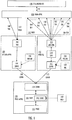
- the system comprises three actors:
- the system is configured to intercept the mobile apparatus 150 as a part of a lawful interception, but the system is external in relation to the cellular radio system 190. In this way, the authorities may perform the lawful interception without any co-operation with the operator of the cellular radio network 190.
- the system is configured to intercept the mobile apparatus 150 during an emergency call, and the system is a part of the cellular radio system 190. In this way, the system may at least parly be embedded in the cellular radio system 190.
- the interrogation apparatus 100 may also be called a false base station. 'False' refers to the fact that the false base station 100 is not a part of the (real) cellular radio network 190 and it does not provide continuous service for the mobile (subscriber) apparatuses 150 and their users.
- the purpose of the false base station 100 is to perform radio interface functions required for implementing a silent call with the mobile apparatus 150. In the silent call, the failse base station 100 may page the mobile apparatus 150 to establish communication.
- the mobile apparatus 150 is interoperable with the real cellular radio network 190, i.e., the mobile apparatus 150 could gain service 192 from the real cellular radio network 190 (but the false base station 100 overrides this, at least momentarily, so that the silent call 160 may be implemented).
- the positioning receiver 116 may be a GNSS (Global Navigation Satellite System) receiver, which generates positioning data based on signals received from Earth-orbiting satellites.
- the GNSS may be GPS (Global Positioning System), Galileo, GLONASS, etc.
- the positioning receiver 116 may also operate according to another positioning technique, such as a radio network -based positioning (using the so-called triangulation, for example).
- the interrogation apparatus 100 and the mobile platform 110 may be separate, distinct apparatuses.
- the processing apparatus 130 may also be an apparatus that is separate and distinct from the interrogation apparatus 100 and the mobile platform. However, depending on the system design, the processing apparatus 130 may partly or wholly be a part of the other actor, such as being a part of the interrogation apparatus 100. It is even feasible that the interrogation apparatus 100 and the mobile platform 110 may be integrated into a combined apparatus.
- the processing apparatus 130 may comprise one or more processors 132 and one or more memories 134 including computer program code 136, wherein the one or more memories 134 and the computer program code 136 are configured to, with the one or more processors 132, cause the performance of the processing apparatus 130.
- the processing apparatus 130 may be implemented wholly or partly as a networked server apparatus.
- the interrogation apparatus 100, the mobile platform 110, and the networked server apparatus 130 may operate according to a client-server architecture, a cloud computing architecture, a peer-to-peer system, or another applicable computing architecture.
- the actors 100, 110, 130 each comprise a communication interface 104, 118, 138 implemented with appropriate wired/wireless communication technologies and standard/proprietary protocols.
- the term 'processor' 132 refers to a device that is capable of processing data.
- the processing apparatus 130 may comprise several processors 132 such as parallel processors or a multicore processor.
- a non-exhaustive list of implementation techniques for the processor 132 and the memory 134 includes, but is not limited to: logic components, standard integrated circuits, application-specific integrated circuits (ASIC), system-on-a-chip (SoC), application-specific standard products (ASSP), microprocessors, microcontrollers, digital signal processors, special-purpose computer chips, field-programmable gate arrays (FPGA), and other suitable electronics structures.
- ASIC application-specific integrated circuits
- SoC system-on-a-chip
- ASSP application-specific standard products
- microprocessors microcontrollers
- digital signal processors special-purpose computer chips
- FPGA field-programmable gate arrays
- the working memory and the non-volatile memory may be implemented by a random-access memory (RAM), dynamic RAM (DRAM), static RAM (SRAM), a flash memory, a solid state disk (SSD), PROM (programmable read-only memory), a suitable semiconductor, or any other means of implementing an electrical computer memory.
- the computer program code 136 may be implemented by software.
- the software may be written by a suitable programming language, and the resulting executable code 136 may be stored in the memory 134 and run by the processor 132.
- a computer-readable medium 140 comprises the computer program code 136, which, when loaded into the one or more processors 132 and executed by the one or more processors 132, causes the processing apparatus 130 to perform a part of the method.
- the computer program code 136 may be in source code form, object code form, executable file, or in some intermediate form, for example.
- the computer-readable medium 140 may comprise at least the following: any entity or device capable of carrying computer program code 136 to the processing apparatus 130, a record medium, a computer memory, a read-only memory, an electrical carrier signal, a telecommunications signal, and a software distribution medium. In some jurisdictions, depending on the legislation and the patent practice, the computer-readable medium 140 may not be the telecommunications signal. In an example embodiment, the computer-readable medium 140 may be a non-transitory computer-readable storage medium.
- one or more radio transceivers may be implemented with the software-defined radio (SDR) 114.
- the one or more radio transceivers contain the required radio frequency parts (for example: the antenna array 112, a low-noise amplifier, band-pass filters, an analog-to-digital converter), but at least some of the traditional hardware components, especially those used for digital signal processing, are implemented with radio interface software running on one or more processing units of the SDR 114.
- the system comprising the three actors 100, 110, 130 is configured to cause the system to perform the method.
- the method starts in 602, and ends in 616.
- the operations are not strictly in chronological order in FIG. 6 , and some of the operations may be performed simultaneously or in an order differing from the given ones. Other functions may also be executed between the operations or within the operations and other data exchanged between the operations. Some of the operations or part of the operations may also be left out or replaced by a corresponding operation or part of the operation. It should be noted that no special order of operations is required, except where necessary due to the logical requirements for the processing order.
- a silent call 160 with the mobile apparatus 150 in a radio cell 210 is implemented with the radio transceiver 102 / the interrogation apparatus 100.
- the radio cell 210 may be an omni cell (implemented by an omnidirectional antenna), but it may also be a sector cell, for example.
- each distinct transmission direction 164, 166, 168 may differ from the adjacent transmission directions by 120 degrees, for example.
- a measurement report 162 is received, with the radio transceiver 102, from the mobile apparatus 150 including received downlink power levels of the radio cell 210 and at least one of the three transmit radio beams 164, 166, 168.
- the received downlink power level of the radio cell 210 is the received downlink power level of the serving cell, whereas the received downlink power levels of the three transmit radio beams 164, 166, 168 are the received downlink power levels of the neighbour cells.
- the measurement report 162 may be transmitted from the interrogation apparatus 100 to the processing apparatus 130.
- a geographical location of the mobile platform 110 is received, by the processing apparatus 130, from the positioning receiver 116 of the mobile platform 110.
- a geographical orientation of the mobile platform 110 is obtained by the processing apparatus 130.
- the geographical orientation may be expressed as an angle 244 between a longitudinal axle 240 of the mobile platform 110 and the compass direction North 242.
- the geographical orientation of the mobile platform 110 may also be expressed as a heading of the longitudinal axle 240 in degrees (0-360 degrees), for example.
- the distinct transmission directions are also known (based on the geographical orientation), as the antenna array 112 is fixed in relation to the mobile platform 110.
- system is caused to perform:
- the mobile platform 110 further comprises an inertial measurement unit (IMU) 120.
- the inertial measurement unit 120 may comprise one accelerometer, gyroscope, and magnetometer for each of the three-dimensional measurement axes to measure mobile platform's 110 specific force, angular rate, and the magnetic field surrounding the mobile platform 110.
- the system is caused to perform:
- a geographical location of the mobile apparatus 150 is calculated, by the processing apparatus 130, based on the received downlink power levels, the geographical location of the mobile platform 110, the distinct transmission directions, and the geographical orientation of the mobile platform 110.
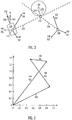
- the system is caused to calculate, by the processing apparatus 130, the geographical location of the mobile apparatus 150 based on the received downlink power levels, the geographical location of the mobile platform 110, the distinct transmission directions, and the geographical orientation of the mobile platform 110 so that a direction of a vector 300 from the mobile platform 110 to the mobile apparatus 150 is calculated based on the distinct transmission direction and the received downlink power level of each received transmit radio beam 164, 166, 168.
- the system is caused to perform:
- the geographical location of the mobile apparatus 150 may be determined by calculating a direction 220 from the mobile platform 110 to the mobile apparatus 150, and, as a distance (based on the timing advance, for example) 250 between the interogation apparatus 100 and the mobile apparatus 150 is known, the location of the mobile apparatus 150 is determined to be in a crossing of the distance 250 and the direction 220. In order this to work, the geographical location of the interrogation apparatus 100 needs to be known.
- the interrogation apparatus 100 is mobile and comprises a user portable pack and/or a land vehicle and/or a vessel, and a positioning receiver 106 of the interrogation apparatus configured to determine a geographical location of the interrogation apparatus 100.
- the system is caused to perform:
- the interrogation apparatus 100 is set stationary at a geographical location of the interrogation apparatus 100.
- the system is caused to calculate 612, by the processing apparatus 130, the geographical location of the mobile apparatus 150 based on the received downlink power levels, the geographical location of the mobile platform 110, the distinct transmission directions, the geographical orientation of the mobile platform 110, and the geographical location of the interrogation apparatus 100.
- the mobile platform 110 comprises an aerial vehicle and/or a land vehicle and/or a vessel. As shown in FIG. 5 , the mobile platform 110 is placed in an unmanned aerial vehicle UAV ("drone").
- UAV unmanned aerial vehicle
- the term “mobile” means that the platform 110 may move (carried by the vehicle/vessel) from one geographical location to another geographical location, or that the platform 110 may be "moveable", i.e., moved by an authorized person to a specific stationary geographical location.
- the software-defined radio 114 and the antenna array 112 are configured to make the at least three transmit radio beams 164, 166, 168 directional by beamforming 624.
- the software-defined radio 114 control the phase and relative amplitude of the signal at each transmitter to create a pattern of constructive and destructive interference, which results in directional signal transmission.
- the software-defined radio (114) is configured to include a different identifier 626 for each of the at least three transmit radio beams 164, 166, 168.
- the different identifiers may be cell identifiers or other identifiers used in the cellular radio network 190 and in the measurement report 162.
- the measurement report, the geographical location of the mobile platform 110, and the geographical orientation of the mobile platform 110 each comprise a time stamp 628, 630, 632 indicating a time of measurement or a time of reception.
- the calculations may be made more precise as the various types of data are matched to each other so that they relate to the same moment in time.
- FIG. 1 and FIG. 5 Let us study FIG. 1 and FIG. 5 illustrating further example embodiments.
- the various tranmission directions may be in horizontal directions only along X and Z axes, but also in a vertical direction along Y axis.
- system is caused to perform:
- system is caused to perform:
- FIG. 2 illustrates another example embodiment, wherein more than one mobile platforms 110, 200 are used.
- the second mobile platform 200 is configured to transmit three further transmit radio beams 202, 204, 206, and the location of the mobile apparatus 150 may be determined at a crossing of the direction vector 220 from the first mobile platform 110 and a direction vector 230 of the second mobile platform 200.
- the measurement report 162 from the mobile apparatus 150 may include received downlink power levels of the radio cell 210, at least one of the three transmit radio beams 164, 166, 168, and at least one of the three further transmit radio beamss 202, 204, 206.
Landscapes
- Engineering & Computer Science (AREA)
- Radar, Positioning & Navigation (AREA)
- Remote Sensing (AREA)
- Business, Economics & Management (AREA)
- Signal Processing (AREA)
- General Physics & Mathematics (AREA)
- Physics & Mathematics (AREA)
- Computer Networks & Wireless Communication (AREA)
- Tourism & Hospitality (AREA)
- Computer Security & Cryptography (AREA)
- General Health & Medical Sciences (AREA)
- Marketing (AREA)
- Development Economics (AREA)
- Health & Medical Sciences (AREA)
- Economics (AREA)
- Technology Law (AREA)
- Human Resources & Organizations (AREA)
- Educational Administration (AREA)
- Primary Health Care (AREA)
- Strategic Management (AREA)
- General Business, Economics & Management (AREA)
- Theoretical Computer Science (AREA)
- Automation & Control Theory (AREA)
- Mobile Radio Communication Systems (AREA)
Abstract
Method and system for intercepting mobile apparatus of cellular radio system. The method includes: implementing (602), with an interrogation apparatus, a silent call with a mobile apparatus in a radio cell; implementing (604), with a mobile platform, at least three transmit radio beams each with a distinct transmission direction in relation to the mobile platform; receiving (606) a measurement report from the mobile apparatus including received downlink power levels of the radio cell and at least one of the three transmit radio beams; receiving (608) a geographical location of the mobile platform; obtaining (610) a geographical orientation of the mobile platform; and calculating (612) a geographical location of the mobile apparatus based on the received downlink power levels, the geographical location of the mobile platform, the distinct transmission directions, and the geographical orientation of the mobile platform.
Description
- Various example embodiments relate to a system and a method for intercepting a mobile apparatus of a cellular radio system.
- A lawful interception of a mobile apparatus by the authorities is sometimes necessary.
US 7035651 B2 ,US 9872141 B2 US 10034126 B2 - According to an aspect, there is provided subject matter of independent claims. Dependent claims define some example embodiments.
- One or more examples of implementations are set forth in more detail in the accompanying drawings and the description of embodiments.
- Some example embodiments will now be described with reference to the accompanying drawings, in which
-
FIG. 1 andFIG. 2 illustrate example embodiments of a system; -
FIG. 3 illustrates an example embodiment of using vectors to calculate a direction of a mobile apparatus; -
FIG. 4 is a signal sequence chart illustrating example embodiments of communication within the system; -
FIG. 5 illustrates further example embodiments of the system; and -
FIG. 6 illustrates example embodiments of a method. - The following embodiments are only examples. Although the specification may refer to "an" embodiment in several locations, this does not necessarily mean that each such reference is to the same embodiment(s), or that the feature only applies to a single embodiment. Single features of different embodiments may also be combined to provide other embodiments. Furthermore, words "comprising" and "including" should be understood as not limiting the described embodiments to consist of only those features that have been mentioned and such embodiments may contain also features/structures that have not been specifically mentioned.
- Reference numbers, both in the description of the example embodiments and in the claims, serve to illustrate the example embodiments with reference to the drawings, without limiting it to these examples only.
- Let us study simultaneously
FIG. 1 , which illustrates example embodiments of a system for intercepting the mobile apparatus,FIG. 6 , which illustrates example embodiments of a method performed by the system, andFIG. 4 , which is a signal sequence chart illustrating example embodiments of communication within the system. - The system is configured to intercept a
mobile apparatus 150 of acellular radio system 190. Themobile apparatus 150 may be a portable / vehicle-mounted user subscriber apparatus (with a subscription to the wireless service implemented by a physical subscriber identity module SIM card, or an embedded SIM eSIM, for example). The mobile apparatus includes, but is not limited to a mobile phone, a smart phone, a smartwatch, or any other type of a portable ICT (Information and communication technology) user apparatus (such as a portable computer, a tablet computer, a connected Internet of Things (loT) device, etc.). - The
mobile apparatus 150 comprises a cellular radio transceiver configured to communicate with thecellular radio network 190 such as a mobile phone system. Thecellular radio network 190 includes but is not limited to a suitable cellular communication technology such as GSM, GPRS, EGPRS, WCDMA, UMTS, 3GPP, IMT, LTE, LTE-A, NR, 3G, 4G, 5G etc. - The system comprises three actors:
- an
interrogation apparatus 100 comprising aradio transceiver 102; - a
mobile platform 110 comprising a software-definedradio 114, anantenna array 112, and apositioning receiver 116 of the mobile platform; and - a
processing apparatus 130, which is communicatively coupled 170, 172 with theinterrogation apparatus 100 and themobile platform 110. - In an example embodiment, the system is configured to intercept the
mobile apparatus 150 as a part of a lawful interception, but the system is external in relation to thecellular radio system 190. In this way, the authorities may perform the lawful interception without any co-operation with the operator of thecellular radio network 190. - In an example embodiment, the system is configured to intercept the
mobile apparatus 150 during an emergency call, and the system is a part of thecellular radio system 190. In this way, the system may at least parly be embedded in thecellular radio system 190. - The
interrogation apparatus 100 may also be called a false base station. 'False' refers to the fact that thefalse base station 100 is not a part of the (real)cellular radio network 190 and it does not provide continuous service for the mobile (subscriber)apparatuses 150 and their users. The purpose of thefalse base station 100 is to perform radio interface functions required for implementing a silent call with themobile apparatus 150. In the silent call, thefailse base station 100 may page themobile apparatus 150 to establish communication.FIG. 1 also illustrates that themobile apparatus 150 is interoperable with the realcellular radio network 190, i.e., themobile apparatus 150 could gainservice 192 from the real cellular radio network 190 (but thefalse base station 100 overrides this, at least momentarily, so that thesilent call 160 may be implemented). - The
positioning receiver 116 may be a GNSS (Global Navigation Satellite System) receiver, which generates positioning data based on signals received from Earth-orbiting satellites. The GNSS may be GPS (Global Positioning System), Galileo, GLONASS, etc. Thepositioning receiver 116 may also operate according to another positioning technique, such as a radio network -based positioning (using the so-called triangulation, for example). - The
interrogation apparatus 100 and themobile platform 110 may be separate, distinct apparatuses. Theprocessing apparatus 130 may also be an apparatus that is separate and distinct from theinterrogation apparatus 100 and the mobile platform. However, depending on the system design, theprocessing apparatus 130 may partly or wholly be a part of the other actor, such as being a part of theinterrogation apparatus 100. It is even feasible that theinterrogation apparatus 100 and themobile platform 110 may be integrated into a combined apparatus. - The
processing apparatus 130 may comprise one ormore processors 132 and one ormore memories 134 includingcomputer program code 136, wherein the one ormore memories 134 and thecomputer program code 136 are configured to, with the one ormore processors 132, cause the performance of theprocessing apparatus 130. - The
processing apparatus 130 may be implemented wholly or partly as a networked server apparatus. Theinterrogation apparatus 100, themobile platform 110, and thenetworked server apparatus 130 may operate according to a client-server architecture, a cloud computing architecture, a peer-to-peer system, or another applicable computing architecture. - In order to communicate, the
actors communication interface - The term 'processor' 132 refers to a device that is capable of processing data. Depending on the processing power needed, the
processing apparatus 130 may compriseseveral processors 132 such as parallel processors or a multicore processor. - A non-exhaustive list of implementation techniques for the
processor 132 and thememory 134 includes, but is not limited to: logic components, standard integrated circuits, application-specific integrated circuits (ASIC), system-on-a-chip (SoC), application-specific standard products (ASSP), microprocessors, microcontrollers, digital signal processors, special-purpose computer chips, field-programmable gate arrays (FPGA), and other suitable electronics structures. - The term 'memory' 134 refers to a device that is capable of storing data run-time (= working memory) or permanently (= non-volatile memory). The working memory and the non-volatile memory may be implemented by a random-access memory (RAM), dynamic RAM (DRAM), static RAM (SRAM), a flash memory, a solid state disk (SSD), PROM (programmable read-only memory), a suitable semiconductor, or any other means of implementing an electrical computer memory.
- The
computer program code 136 may be implemented by software. In an example embodiment, the software may be written by a suitable programming language, and the resultingexecutable code 136 may be stored in thememory 134 and run by theprocessor 132. - In an example embodiment of
FIG. 1 , a computer-readable medium 140 comprises thecomputer program code 136, which, when loaded into the one ormore processors 132 and executed by the one ormore processors 132, causes theprocessing apparatus 130 to perform a part of the method. - In an example embodiment, the
computer program code 136 may be in source code form, object code form, executable file, or in some intermediate form, for example. The computer-readable medium 140, may comprise at least the following: any entity or device capable of carryingcomputer program code 136 to theprocessing apparatus 130, a record medium, a computer memory, a read-only memory, an electrical carrier signal, a telecommunications signal, and a software distribution medium. In some jurisdictions, depending on the legislation and the patent practice, the computer-readable medium 140 may not be the telecommunications signal. In an example embodiment, the computer-readable medium 140 may be a non-transitory computer-readable storage medium. - In the
mobile platform 110, one or more radio transceivers may be implemented with the software-defined radio (SDR) 114. Using theSDR 114, the one or more radio transceivers contain the required radio frequency parts (for example: theantenna array 112, a low-noise amplifier, band-pass filters, an analog-to-digital converter), but at least some of the traditional hardware components, especially those used for digital signal processing, are implemented with radio interface software running on one or more processing units of theSDR 114. - The system comprising the three
actors - The method starts in 602, and ends in 616.
- The operations are not strictly in chronological order in
FIG. 6 , and some of the operations may be performed simultaneously or in an order differing from the given ones. Other functions may also be executed between the operations or within the operations and other data exchanged between the operations. Some of the operations or part of the operations may also be left out or replaced by a corresponding operation or part of the operation. It should be noted that no special order of operations is required, except where necessary due to the logical requirements for the processing order. - In 602, a
silent call 160 with themobile apparatus 150 in aradio cell 210 is implemented with theradio transceiver 102 / theinterrogation apparatus 100. As shown inFIG. 2 , theradio cell 210 may be an omni cell (implemented by an omnidirectional antenna), but it may also be a sector cell, for example. - In 604, at least three transmit
radio beams mobile platform 110 are implemented with the software-definedradio 114 and theantenna array 112 / themobile platform 110. As shown inFIG. 2 , eachdistinct transmission direction - In 606, a
measurement report 162 is received, with theradio transceiver 102, from themobile apparatus 150 including received downlink power levels of theradio cell 210 and at least one of the three transmitradio beams radio cell 210 is the received downlink power level of the serving cell, whereas the received downlink power levels of the three transmitradio beams - In an
optional operation 400, themeasurement report 162 may be transmitted from theinterrogation apparatus 100 to theprocessing apparatus 130. - In 608/402, a geographical location of the
mobile platform 110 is received, by theprocessing apparatus 130, from thepositioning receiver 116 of themobile platform 110. - In 610, a geographical orientation of the
mobile platform 110 is obtained by theprocessing apparatus 130. As shown inFIG. 2 , the geographical orientation may be expressed as anangle 244 between alongitudinal axle 240 of themobile platform 110 and thecompass direction North 242. The geographical orientation of themobile platform 110 may also be expressed as a heading of thelongitudinal axle 240 in degrees (0-360 degrees), for example. The distinct transmission directions are also known (based on the geographical orientation), as theantenna array 112 is fixed in relation to themobile platform 110. - In an example embodiment, the system is caused to perform:
- receiving 620, by the processing apparatus (130), movement direction data from the
positioning receiver 116 of the mobile platform; and - processing 620, by the
processing apparatus 130, the movement direction data to detect the geographical orientation of themobile platform 110. Such data may be in an NMEA (The National Marine Electronics Association) VTG message as a measured heading in degrees, for example. - In an example embodiment, the
mobile platform 110 further comprises an inertial measurement unit (IMU) 120. Theinertial measurement unit 120 may comprise one accelerometer, gyroscope, and magnetometer for each of the three-dimensional measurement axes to measure mobile platform's 110 specific force, angular rate, and the magnetic field surrounding themobile platform 110. The system is caused to perform: - receiving 622, by the
processing apparatus 130, inertial measurement data from theinertial measurement unit 120; and - processing 622, by the
processing apparatus 130, the inertial measurement data to detect the geographical orientation of themobile platform 110. - In 612, a geographical location of the
mobile apparatus 150 is calculated, by theprocessing apparatus 130, based on the received downlink power levels, the geographical location of themobile platform 110, the distinct transmission directions, and the geographical orientation of themobile platform 110. - In an example embodiment illustrated in
FIG. 3 , the system is caused to calculate, by theprocessing apparatus 130, the geographical location of themobile apparatus 150 based on the received downlink power levels, the geographical location of themobile platform 110, the distinct transmission directions, and the geographical orientation of themobile platform 110 so that a direction of avector 300 from themobile platform 110 to themobile apparatus 150 is calculated based on the distinct transmission direction and the received downlink power level of each received transmitradio beam - In an example embodiment illustrated with a
loop 614 from theoperation 612 back to theoperation 606, the system is caused to perform: - receiving 606, with the
radio transceiver 102, a subsequent measurement report from themobile apparatus 150 including subsequent received downlink power levels of theradio cell 210 and at least one of the three transmitradio beams - receiving 608, by the
processing apparatus 130, a subsequent geographical location of themobile platform 110 from thepositioning receiver 116 of the mobile platform; - obtaining 610, by the
processing apparatus 130, a subsequent geographical orientation of themobile platform 110; and - calculating 612, by the
processing apparatus 130, the geographical location of themobile apparatus 150 based on the received downlink power levels, the geographical location of themobile platform 110, the distinct transmission directions, the geographical orientation of themobile platform 110, the subsequent received downlink power levels, the subsequent geographical location of themobile platform 110, and the subsequent geographical orientation of themobile platform 110 so that a further direction of a further vector from themobile platform 110 to themobile apparatus 150 is calculated based on the distinct transmission direction and the received downlink power level of each subsequently received transmitradio beam intersection point 634 of the vector and the further vector indicates the geographical location of themobile apparatus 150. - As shown in
FIG. 2 , the geographical location of themobile apparatus 150 may be determined by calculating adirection 220 from themobile platform 110 to themobile apparatus 150, and, as a distance (based on the timing advance, for example) 250 between theinterogation apparatus 100 and themobile apparatus 150 is known, the location of themobile apparatus 150 is determined to be in a crossing of thedistance 250 and thedirection 220. In order this to work, the geographical location of theinterrogation apparatus 100 needs to be known. - In an example embodiment, the
interrogation apparatus 100 is mobile and comprises a user portable pack and/or a land vehicle and/or a vessel, and apositioning receiver 106 of the interrogation apparatus configured to determine a geographical location of theinterrogation apparatus 100. The system is caused to perform: - receiving 618, by the processing apparatus, a geographical location of the
interrogation apparatus 100 from thepositioning receiver 106 of the interrogation apparatus; and - calculating 612, by the
processing apparatus 130, the geographical location of themobile apparatus 150 based on the received downlink power levels, the geographical location of themobile platform 110, the distinct transmission directions, the geographical orientation of themobile platform 110, and the geographical location of theinterrogation apparatus 100. - In an example embodiment, the
interrogation apparatus 100 is set stationary at a geographical location of theinterrogation apparatus 100. The system is caused to calculate 612, by theprocessing apparatus 130, the geographical location of themobile apparatus 150 based on the received downlink power levels, the geographical location of themobile platform 110, the distinct transmission directions, the geographical orientation of themobile platform 110, and the geographical location of theinterrogation apparatus 100. - In an example embodiment, the
mobile platform 110 comprises an aerial vehicle and/or a land vehicle and/or a vessel. As shown inFIG. 5 , themobile platform 110 is placed in an unmanned aerial vehicle UAV ("drone"). Note that the term "mobile" means that theplatform 110 may move (carried by the vehicle/vessel) from one geographical location to another geographical location, or that theplatform 110 may be "moveable", i.e., moved by an authorized person to a specific stationary geographical location. - In an example embodiment, the software-defined
radio 114 and theantenna array 112 are configured to make the at least three transmitradio beams beamforming 624. The software-definedradio 114 control the phase and relative amplitude of the signal at each transmitter to create a pattern of constructive and destructive interference, which results in directional signal transmission. - In an example embodiment, the software-defined radio (114) is configured to include a
different identifier 626 for each of the at least three transmitradio beams cellular radio network 190 and in themeasurement report 162. - In an example embodiment, the measurement report, the geographical location of the
mobile platform 110, and the geographical orientation of themobile platform 110 each comprise atime stamp - Let us study
FIG. 1 andFIG. 5 illustrating further example embodiments. - The various tranmission directions may be in horizontal directions only along X and Z axes, but also in a vertical direction along Y axis.
- In an example embodiment, the system is caused to perform:
- implementing 604, with the software-defined
radio 114 and theantenna array 112, the at least three transmitradio beams - calculating 612, by the
processing apparatus 130, the geographical location of themobile apparatus 150 as a latitude and a longitude on an electronic map based on the received downlink power levels, the geographical location of themobile platform 110, the distinct horizontal transmission directions, and the geographical orientation of themobile platform 110. This example embodiment utilizes the horizontal directions only as inFIG. 2 . - In an example embodiment, the system is caused to perform:
- implementing 604, with the software-defined
radio 114 and theantenna array 112, at least three further transmitradio beams - receiving 606, with the
radio transceiver 102, themeasurement report 162 from themobile apparatus 150 including received downlink power levels of theradio cell 210, at least one of the three transmitradio beams radio beams - calculating 612, by the
processing apparatus 130, the geographical location of themobile apparatus 150 as the latitude, the longitude and the elevation on the electronic map based on the received downlink power levels, the geographical location of themobile platform 110, the distinct horizontal transmission directions, the further distinct vertical transmission directions, and the geographical orientation of themobile platform 110. This example embodiment uses besides the horizontal directions also the vertical directions. As show inFIG. 5 , the location of themobile apparatus 150 is indicated by a direction of a three-dimensional vector 500 (by an intersection of two such vectors or by an intersection of such a vector and a distance based on the timing advance in the cell, as explained earlier, or by an intersection of the vector and the Earth's ground plane). -
FIG. 2 illustrates another example embodiment, wherein more than onemobile platforms mobile platform 200 is configured to transmit three further transmitradio beams mobile apparatus 150 may be determined at a crossing of thedirection vector 220 from the firstmobile platform 110 and adirection vector 230 of the secondmobile platform 200. Themeasurement report 162 from themobile apparatus 150 may include received downlink power levels of theradio cell 210, at least one of the three transmitradio beams radio beamss - Even though the invention has been described with reference to one or more example embodiments according to the accompanying drawings, it is clear that the invention is not restricted thereto but can be modified in several ways within the scope of the appended claims. All words and expressions should be interpreted broadly, and they are intended to illustrate, not to restrict, the example embodiments. It will be obvious to a person skilled in the art that, as technology advances, the inventive concept can be implemented in various ways.
Claims (15)
- A system for intercepting a mobile apparatus (150) of a cellular radio system (190), comprising:an interrogation apparatus (100) comprising a radio transceiver (102);a mobile platform (110) comprising a software-defined radio (114), an antenna array (112), and a positioning receiver (116) of the mobile platform; anda processing apparatus (130), communicatively coupled (170, 172) with the interrogation apparatus (100) and the mobile platform (110);which cause the system at least to perform:implementing (602), with the radio transceiver (102), a silent call (160) with the mobile apparatus (150) in a radio cell (210);implementing (604), with the software-defined radio (114) and the antenna array (112), at least three transmit radio beams (164, 166, 168) each with a distinct transmission direction in relation to the mobile platform (110);receiving (606), with the radio transceiver (102), a measurement report (162) from the mobile apparatus (150) including received downlink power levels of the radio cell (210) and at least one of the three transmit radio beams (164, 166, 168);receiving (608), by the processing apparatus (130), a geographical location of the mobile platform (110) from the positioning receiver (116) of the mobile platform;obtaining (610), by the processing apparatus (130), a geographical orientation of the mobile platform (110); andcalculating (612), by the processing apparatus (130), a geographical location of the mobile apparatus (150) based on the received downlink power levels, the geographical location of the mobile platform (110), the distinct transmission directions, and the geographical orientation of the mobile platform (110).
- The system of claim 1, wherein the interrogation apparatus (100) is mobile and comprises a user portable pack and/or a land vehicle and/or a vessel, and a positioning receiver (106) of the interrogation apparatus configured to determine a geographical location of the interrogation apparatus (100), and wherein the system is caused to perform:receiving (618), by the processing apparatus, a geographical location of the interrogation apparatus (100) from the positioning receiver (106) of the interrogation apparatus; andcalculating (612), by the processing apparatus (130), the geographical location of the mobile apparatus (150) based on the received downlink power levels, the geographical location of the mobile platform (110), the distinct transmission directions, the geographical orientation of the mobile platform (110), and the geographical location of the interrogation apparatus (100).
- The system of claim 1, wherein the interrogation apparatus (100) is set stationary at a geographical location of the interrogation apparatus (100), and wherein the system is caused to perform:
calculating (612), by the processing apparatus (130), the geographical location of the mobile apparatus (150) based on the received downlink power levels, the geographical location of the mobile platform (110), the distinct transmission directions, the geographical orientation of the mobile platform (110), and the geographical location of the interrogation apparatus (100). - The system of any preceding claim, wherein the mobile platform (110) comprises an aerial vehicle and/or a land vehicle and/or a vessel.
- The system of any preceding claim, wherein the software-defined radio (114) and the antenna array (112) are configured to make the at least three transmit radio beams (164, 166, 168) directional by beamforming (624).
- The system of any preceding claim, wherein the software-defined radio (114) is configured to include a different identifier (626) for each of the at least three transmit radio beams (164, 166, 168).
- The system of any preceding claim, wherein the measurement report, the geographical location of the mobile platform (110), and the geographical orientation of the mobile platform (110) each comprise a time stamp (628, 630, 632) indicating a time of measurement or a time of reception.
- The system of any preceding claim, wherein the system is caused to perform:receiving (620), by the processing apparatus (130), movement direction data from the positioning receiver (116) of the mobile platform; andprocessing (620), by the processing apparatus (130), the movement direction data to detect the geographical orientation of the mobile platform (110).
- The system of any preceding claim, wherein the mobile platform (110) further comprises an inertial measurement unit (120), and wherein the system is caused to perform:receiving (622), by the processing apparatus (130), inertial measurement data from the inertial measurement unit (120); andprocessing (622), by the processing apparatus (130), the inertial measurement data to detect the geographical orientation of the mobile platform (110).
- The system of any preceding claim, wherein the system is caused to perform:
calculating (612), by the processing apparatus (130), the geographical location of the mobile apparatus (150) based on the received downlink power levels, the geographical location of the mobile platform (110), the distinct transmission directions, and the geographical orientation of the mobile platform (110) so that a direction of a vector (300) from the mobile platform (110) to the mobile apparatus (150) is calculated based on the distinct transmission direction and the received downlink power level of each received transmit radio beam (164, 166, 168). - The system of claim 10, wherein the system is caused to perform:receiving (606), with the radio transceiver (102), a subsequent measurement report from the mobile apparatus (150) including subsequent received downlink power levels of the radio cell (210) and at least one of the three transmit radio beams (164, 166, 168);receiving (608), by the processing apparatus (130), a subsequent geographical location of the mobile platform (110) from the positioning receiver (116) of the mobile platform;obtaining (610), by the processing apparatus (130), a subsequent geographical orientation of the mobile platform (110); andcalculating (612), by the processing apparatus (130), the geographical location of the mobile apparatus (150) based on the received downlink power levels, the geographical location of the mobile platform (110), the distinct transmission directions, the geographical orientation of the mobile platform (110), the subsequent received downlink power levels, the subsequent geographical location of the mobile platform (110), and the subsequent geographical orientation of the mobile platform (110) so that a further direction of a further vector from the mobile platform (110) to the mobile apparatus (150) is calculated based on the distinct transmission direction and the received downlink power level of each subsequently received transmit radio beam (164, 166, 168), and an intersection point (634) of the vector and the further vector indicates the geographical location of the mobile apparatus (150).
- The system of any preceding claim, wherein the system is caused to perform:implementing (604), with the software-defined radio (114) and the antenna array (112), the at least three transmit radio beams (164, 166, 168) each with the distinct transmission direction so that the distinct transmission directions are horizontal (170); andcalculating (612), by the processing apparatus (130), the geographical location of the mobile apparatus (150) as a latitude and a longitude on an electronic map based on the received downlink power levels, the geographical location of the mobile platform (110), the distinct horizontal transmission directions, and the geographical orientation of the mobile platform (110).
- The system of the claim 12, wherein the system is caused to perform:implementing (604), with the software-defined radio (114) and the antenna array (112), at least three further transmit radio beams (182, 184, 186) each with a further distinct transmission direction so that the further distinct transmission directions are vertical (180);receiving (606), with the radio transceiver (102), the measurement report (162) from the mobile apparatus (150) including received downlink power levels of the radio cell (210), at least one of the three transmit radio beams (164, 166, 168), and at least one of the three further transmit radio beams (182, 184, 186); andcalculating (612), by the processing apparatus (130), the geographical location of the mobile apparatus (150) as the latitude, the longitude and the elevation on the electronic map based on the received downlink power levels, the geographical location of the mobile platform (110), the distinct horizontal transmission directions, the further distinct vertical transmission directions, and the geographical orientation of the mobile platform (110).
- The system of any preceding claim 1 to 13, wherein:the system is configured to intercept the mobile apparatus (150) as a part of a lawful interception, but the system is external in relation to the cellular radio system (190); orthe system is configured to intercept the mobile apparatus (150) during an emergency call, and the system is a part of the cellular radio system (190).
- A method for intercepting a mobile apparatus of a cellular radio system, comprising:implementing (602), with an interrogation apparatus, a silent call with a mobile apparatus in a radio cell;implementing (604), with a mobile platform, at least three transmit radio beams each with a distinct transmission direction in relation to the mobile platform;receiving (606) a measurement report from the mobile apparatus including received downlink power levels of the radio cell and at least one of the three transmit radio beams;receiving (608) a geographical location of the mobile platform;obtaining (610) a geographical orientation of the mobile platform; andcalculating (612) a geographical location of the mobile apparatus based on the received downlink power levels, the geographical location of the mobile platform, the distinct transmission directions, and the geographical orientation of the mobile platform.
Priority Applications (2)
| Application Number | Priority Date | Filing Date | Title |
|---|---|---|---|
| EP19159063.7A EP3699626A1 (en) | 2019-02-25 | 2019-02-25 | Interception of mobile apparatus |
| US16/799,257 US11501398B2 (en) | 2019-02-25 | 2020-02-24 | Interception of mobile apparatus |
Applications Claiming Priority (1)
| Application Number | Priority Date | Filing Date | Title |
|---|---|---|---|
| EP19159063.7A EP3699626A1 (en) | 2019-02-25 | 2019-02-25 | Interception of mobile apparatus |
Publications (1)
| Publication Number | Publication Date |
|---|---|
| EP3699626A1 true EP3699626A1 (en) | 2020-08-26 |
Family
ID=65576189
Family Applications (1)
| Application Number | Title | Priority Date | Filing Date |
|---|---|---|---|
| EP19159063.7A Withdrawn EP3699626A1 (en) | 2019-02-25 | 2019-02-25 | Interception of mobile apparatus |
Country Status (2)
| Country | Link |
|---|---|
| US (1) | US11501398B2 (en) |
| EP (1) | EP3699626A1 (en) |
Citations (6)
| Publication number | Priority date | Publication date | Assignee | Title |
|---|---|---|---|---|
| US7035651B2 (en) | 2002-02-28 | 2006-04-25 | Alcatel | Process and devices for determining the radio reception direction in a mobile communications network |
| US20140302869A1 (en) * | 2011-02-24 | 2014-10-09 | Glen Var Rosenbaum | Beacon and associated components for a ranging system |
| US20160195603A1 (en) * | 2012-06-14 | 2016-07-07 | Telefonaktiebolaget L M Ericsson (Publ) | Method and apparatus for position determination |
| US20160295366A1 (en) * | 2015-03-31 | 2016-10-06 | Sony Corporation | Method and apparatus for positioning a mobile terminal in a radio network |
| US9872141B2 (en) | 2015-05-14 | 2018-01-16 | Verint Systems Ltd. | System and method for accurate location of wireless terminals using mobile interrogation device |
| US10034126B2 (en) | 2013-03-21 | 2018-07-24 | Verint Systems Ltd. | Stand alone solution for location of a cellular phone |
Family Cites Families (2)
| Publication number | Priority date | Publication date | Assignee | Title |
|---|---|---|---|---|
| DE10051129A1 (en) | 2000-10-16 | 2002-04-18 | Rohde & Schwarz | Mobile telephone activation method has base station providing set-up signal for called mobile telephone replaced by channel release signal upon reception of identification parameters |
| EP3788723A1 (en) * | 2018-05-03 | 2021-03-10 | Telefonaktiebolaget Lm Ericsson (Publ) | Systems and methods of controlling a component of a network node in a communication system |
-
2019
- 2019-02-25 EP EP19159063.7A patent/EP3699626A1/en not_active Withdrawn
-
2020
- 2020-02-24 US US16/799,257 patent/US11501398B2/en active Active
Patent Citations (6)
| Publication number | Priority date | Publication date | Assignee | Title |
|---|---|---|---|---|
| US7035651B2 (en) | 2002-02-28 | 2006-04-25 | Alcatel | Process and devices for determining the radio reception direction in a mobile communications network |
| US20140302869A1 (en) * | 2011-02-24 | 2014-10-09 | Glen Var Rosenbaum | Beacon and associated components for a ranging system |
| US20160195603A1 (en) * | 2012-06-14 | 2016-07-07 | Telefonaktiebolaget L M Ericsson (Publ) | Method and apparatus for position determination |
| US10034126B2 (en) | 2013-03-21 | 2018-07-24 | Verint Systems Ltd. | Stand alone solution for location of a cellular phone |
| US20160295366A1 (en) * | 2015-03-31 | 2016-10-06 | Sony Corporation | Method and apparatus for positioning a mobile terminal in a radio network |
| US9872141B2 (en) | 2015-05-14 | 2018-01-16 | Verint Systems Ltd. | System and method for accurate location of wireless terminals using mobile interrogation device |
Also Published As
| Publication number | Publication date |
|---|---|
| US20200273129A1 (en) | 2020-08-27 |
| US11501398B2 (en) | 2022-11-15 |
Similar Documents
| Publication | Publication Date | Title |
|---|---|---|
| US20210333410A1 (en) | Sps spoofing detection | |
| Gao et al. | Cooperative localization and navigation: theory, research, and Practice | |
| US11937280B2 (en) | Frequency and state dependent user equipment beam patterns | |
| EP3243088B1 (en) | Automotive ad hoc real time kinematics roving network | |
| US9736649B1 (en) | Antenna positioning using data across air interface types | |
| US11892546B2 (en) | Systems and methods for detecting and mitigating spoofed satellite navigation signals | |
| US11796687B2 (en) | Method and apparatus for location determination using plate tectonics models | |
| EP1253436A1 (en) | System and method for locating mobile radios outside the coverage of a cellular network | |
| CN113196107A (en) | Information processing method and terminal equipment | |
| WO2022231687A1 (en) | Enhanced messaging to handle sps spoofing | |
| García et al. | Location-based services in cellular networks: from GSM to 5G NR | |
| WO2020172470A1 (en) | Techniques for using rotation vectors for beam management in high frequency wireless networks | |
| KR20150013042A (en) | Portable device, mobile terminal, database server, and system using visibility mask information, and operating method of portable device | |
| US11501398B2 (en) | Interception of mobile apparatus | |
| Fernandez-Prades et al. | Assisted GNSS in LTE-advanced networks and its application to vector tracking loops | |
| US20240085514A1 (en) | Determining an orientation of a user equipment with a cellular network | |
| US20240094414A1 (en) | Carrier signal positioning | |
| Calatrava Rodríguez | Cooperative Positioning using Massive Differentiation of GNSS Pseudorange Measurements | |
| Zhang et al. | RIS-Assisted Cooperative Positioning for Smart Vehicles with Extended Kalman Filter and AOA Measurements | |
| Nguyen-Tan et al. | GPS Signal Reception and Spoofing Based on Software-Defined Radio Devices | |
| WO2023235831A1 (en) | Precise attitude determination and positioning system | |
| EP4133819A1 (en) | Multi-path positioning signal determination |
Legal Events
| Date | Code | Title | Description |
|---|---|---|---|
| PUAI | Public reference made under article 153(3) epc to a published international application that has entered the european phase |
Free format text: ORIGINAL CODE: 0009012 |
|
| STAA | Information on the status of an ep patent application or granted ep patent |
Free format text: STATUS: THE APPLICATION HAS BEEN PUBLISHED |
|
| AK | Designated contracting states |
Kind code of ref document: A1 Designated state(s): AL AT BE BG CH CY CZ DE DK EE ES FI FR GB GR HR HU IE IS IT LI LT LU LV MC MK MT NL NO PL PT RO RS SE SI SK SM TR |
|
| AX | Request for extension of the european patent |
Extension state: BA ME |
|
| STAA | Information on the status of an ep patent application or granted ep patent |
Free format text: STATUS: THE APPLICATION IS DEEMED TO BE WITHDRAWN |
|
| 18D | Application deemed to be withdrawn |
Effective date: 20210227 |