EP3697183B1 - Rack adapted for receiving a component, system including the rack and the component and method of delivering power to a component mounted in a rack - Google Patents
Rack adapted for receiving a component, system including the rack and the component and method of delivering power to a component mounted in a rack Download PDFInfo
- Publication number
- EP3697183B1 EP3697183B1 EP19315006.7A EP19315006A EP3697183B1 EP 3697183 B1 EP3697183 B1 EP 3697183B1 EP 19315006 A EP19315006 A EP 19315006A EP 3697183 B1 EP3697183 B1 EP 3697183B1
- Authority
- EP
- European Patent Office
- Prior art keywords
- power
- component
- backplane
- rack
- stage
- Prior art date
- Legal status (The legal status is an assumption and is not a legal conclusion. Google has not performed a legal analysis and makes no representation as to the accuracy of the status listed.)
- Active
Links
- 238000000034 method Methods 0.000 title claims description 17
- 238000003780 insertion Methods 0.000 claims description 25
- 230000037431 insertion Effects 0.000 claims description 25
- 230000000295 complement effect Effects 0.000 claims description 14
- 238000005259 measurement Methods 0.000 claims description 10
- 238000012790 confirmation Methods 0.000 claims description 9
- 230000009977 dual effect Effects 0.000 claims description 7
- 238000012795 verification Methods 0.000 claims description 6
- 238000013507 mapping Methods 0.000 claims description 4
- 238000005516 engineering process Methods 0.000 description 81
- 239000007788 liquid Substances 0.000 description 27
- 230000007935 neutral effect Effects 0.000 description 22
- 238000010586 diagram Methods 0.000 description 17
- 238000001816 cooling Methods 0.000 description 11
- 230000006870 function Effects 0.000 description 6
- 238000012986 modification Methods 0.000 description 6
- 230000004048 modification Effects 0.000 description 6
- 230000004044 response Effects 0.000 description 5
- 238000004891 communication Methods 0.000 description 4
- 230000033001 locomotion Effects 0.000 description 4
- 238000007726 management method Methods 0.000 description 4
- 230000013011 mating Effects 0.000 description 4
- 238000001514 detection method Methods 0.000 description 3
- 230000000694 effects Effects 0.000 description 3
- 238000009434 installation Methods 0.000 description 3
- 238000012423 maintenance Methods 0.000 description 3
- 238000012545 processing Methods 0.000 description 3
- 238000004590 computer program Methods 0.000 description 2
- 238000013500 data storage Methods 0.000 description 2
- XLYOFNOQVPJJNP-UHFFFAOYSA-N water Substances O XLYOFNOQVPJJNP-UHFFFAOYSA-N 0.000 description 2
- 230000002159 abnormal effect Effects 0.000 description 1
- 230000009471 action Effects 0.000 description 1
- 230000006978 adaptation Effects 0.000 description 1
- 238000013459 approach Methods 0.000 description 1
- 239000000110 cooling liquid Substances 0.000 description 1
- 230000001419 dependent effect Effects 0.000 description 1
- 230000002779 inactivation Effects 0.000 description 1
- 230000000977 initiatory effect Effects 0.000 description 1
- 238000012806 monitoring device Methods 0.000 description 1
- 238000012544 monitoring process Methods 0.000 description 1
- 230000008569 process Effects 0.000 description 1
- 230000011664 signaling Effects 0.000 description 1
- 239000007787 solid Substances 0.000 description 1
- 239000013589 supplement Substances 0.000 description 1
- 230000007704 transition Effects 0.000 description 1
- 238000009423 ventilation Methods 0.000 description 1
Images


Classifications
-
- H—ELECTRICITY
- H05—ELECTRIC TECHNIQUES NOT OTHERWISE PROVIDED FOR
- H05K—PRINTED CIRCUITS; CASINGS OR CONSTRUCTIONAL DETAILS OF ELECTRIC APPARATUS; MANUFACTURE OF ASSEMBLAGES OF ELECTRICAL COMPONENTS
- H05K7/00—Constructional details common to different types of electric apparatus
- H05K7/14—Mounting supporting structure in casing or on frame or rack
- H05K7/1438—Back panels or connecting means therefor; Terminals; Coding means to avoid wrong insertion
- H05K7/1457—Power distribution arrangements
-
- H—ELECTRICITY
- H02—GENERATION; CONVERSION OR DISTRIBUTION OF ELECTRIC POWER
- H02B—BOARDS, SUBSTATIONS OR SWITCHING ARRANGEMENTS FOR THE SUPPLY OR DISTRIBUTION OF ELECTRIC POWER
- H02B1/00—Frameworks, boards, panels, desks, casings; Details of substations or switching arrangements
- H02B1/26—Casings; Parts thereof or accessories therefor
- H02B1/30—Cabinet-type casings; Parts thereof or accessories therefor
- H02B1/32—Mounting of devices therein
- H02B1/34—Racks
-
- H—ELECTRICITY
- H05—ELECTRIC TECHNIQUES NOT OTHERWISE PROVIDED FOR
- H05K—PRINTED CIRCUITS; CASINGS OR CONSTRUCTIONAL DETAILS OF ELECTRIC APPARATUS; MANUFACTURE OF ASSEMBLAGES OF ELECTRICAL COMPONENTS
- H05K7/00—Constructional details common to different types of electric apparatus
- H05K7/14—Mounting supporting structure in casing or on frame or rack
- H05K7/1485—Servers; Data center rooms, e.g. 19-inch computer racks
- H05K7/1488—Cabinets therefor, e.g. chassis or racks or mechanical interfaces between blades and support structures
- H05K7/1491—Cabinets therefor, e.g. chassis or racks or mechanical interfaces between blades and support structures having cable management arrangements
-
- G—PHYSICS
- G06—COMPUTING; CALCULATING OR COUNTING
- G06F—ELECTRIC DIGITAL DATA PROCESSING
- G06F1/00—Details not covered by groups G06F3/00 - G06F13/00 and G06F21/00
- G06F1/26—Power supply means, e.g. regulation thereof
- G06F1/28—Supervision thereof, e.g. detecting power-supply failure by out of limits supervision
-
- H—ELECTRICITY
- H02—GENERATION; CONVERSION OR DISTRIBUTION OF ELECTRIC POWER
- H02H—EMERGENCY PROTECTIVE CIRCUIT ARRANGEMENTS
- H02H7/00—Emergency protective circuit arrangements specially adapted for specific types of electric machines or apparatus or for sectionalised protection of cable or line systems, and effecting automatic switching in the event of an undesired change from normal working conditions
- H02H7/20—Emergency protective circuit arrangements specially adapted for specific types of electric machines or apparatus or for sectionalised protection of cable or line systems, and effecting automatic switching in the event of an undesired change from normal working conditions for electronic equipment
-
- H—ELECTRICITY
- H05—ELECTRIC TECHNIQUES NOT OTHERWISE PROVIDED FOR
- H05K—PRINTED CIRCUITS; CASINGS OR CONSTRUCTIONAL DETAILS OF ELECTRIC APPARATUS; MANUFACTURE OF ASSEMBLAGES OF ELECTRICAL COMPONENTS
- H05K7/00—Constructional details common to different types of electric apparatus
- H05K7/14—Mounting supporting structure in casing or on frame or rack
- H05K7/1417—Mounting supporting structure in casing or on frame or rack having securing means for mounting boards, plates or wiring boards
-
- H—ELECTRICITY
- H05—ELECTRIC TECHNIQUES NOT OTHERWISE PROVIDED FOR
- H05K—PRINTED CIRCUITS; CASINGS OR CONSTRUCTIONAL DETAILS OF ELECTRIC APPARATUS; MANUFACTURE OF ASSEMBLAGES OF ELECTRICAL COMPONENTS
- H05K7/00—Constructional details common to different types of electric apparatus
- H05K7/14—Mounting supporting structure in casing or on frame or rack
- H05K7/1438—Back panels or connecting means therefor; Terminals; Coding means to avoid wrong insertion
- H05K7/1439—Back panel mother boards
-
- H—ELECTRICITY
- H05—ELECTRIC TECHNIQUES NOT OTHERWISE PROVIDED FOR
- H05K—PRINTED CIRCUITS; CASINGS OR CONSTRUCTIONAL DETAILS OF ELECTRIC APPARATUS; MANUFACTURE OF ASSEMBLAGES OF ELECTRICAL COMPONENTS
- H05K7/00—Constructional details common to different types of electric apparatus
- H05K7/14—Mounting supporting structure in casing or on frame or rack
- H05K7/1438—Back panels or connecting means therefor; Terminals; Coding means to avoid wrong insertion
- H05K7/1459—Circuit configuration, e.g. routing signals
-
- H—ELECTRICITY
- H05—ELECTRIC TECHNIQUES NOT OTHERWISE PROVIDED FOR
- H05K—PRINTED CIRCUITS; CASINGS OR CONSTRUCTIONAL DETAILS OF ELECTRIC APPARATUS; MANUFACTURE OF ASSEMBLAGES OF ELECTRICAL COMPONENTS
- H05K7/00—Constructional details common to different types of electric apparatus
- H05K7/14—Mounting supporting structure in casing or on frame or rack
- H05K7/1485—Servers; Data center rooms, e.g. 19-inch computer racks
- H05K7/1488—Cabinets therefor, e.g. chassis or racks or mechanical interfaces between blades and support structures
- H05K7/1489—Cabinets therefor, e.g. chassis or racks or mechanical interfaces between blades and support structures characterized by the mounting of blades therein, e.g. brackets, rails, trays
-
- H—ELECTRICITY
- H05—ELECTRIC TECHNIQUES NOT OTHERWISE PROVIDED FOR
- H05K—PRINTED CIRCUITS; CASINGS OR CONSTRUCTIONAL DETAILS OF ELECTRIC APPARATUS; MANUFACTURE OF ASSEMBLAGES OF ELECTRICAL COMPONENTS
- H05K7/00—Constructional details common to different types of electric apparatus
- H05K7/14—Mounting supporting structure in casing or on frame or rack
- H05K7/1485—Servers; Data center rooms, e.g. 19-inch computer racks
- H05K7/1488—Cabinets therefor, e.g. chassis or racks or mechanical interfaces between blades and support structures
- H05K7/1492—Cabinets therefor, e.g. chassis or racks or mechanical interfaces between blades and support structures having electrical distribution arrangements, e.g. power supply or data communications
-
- H—ELECTRICITY
- H05—ELECTRIC TECHNIQUES NOT OTHERWISE PROVIDED FOR
- H05K—PRINTED CIRCUITS; CASINGS OR CONSTRUCTIONAL DETAILS OF ELECTRIC APPARATUS; MANUFACTURE OF ASSEMBLAGES OF ELECTRICAL COMPONENTS
- H05K7/00—Constructional details common to different types of electric apparatus
- H05K7/20—Modifications to facilitate cooling, ventilating, or heating
- H05K7/20709—Modifications to facilitate cooling, ventilating, or heating for server racks or cabinets; for data centers, e.g. 19-inch computer racks
- H05K7/20763—Liquid cooling without phase change
- H05K7/20781—Liquid cooling without phase change within cabinets for removing heat from server blades
Definitions
- the present technology relates to enclosures adapted to receive and provide power to electronic equipment.
- a rack adapted for receiving a component a system including the rack and the component and a method of delivering power to a component mounted in a rack are disclosed.
- Electronic devices for example servers, memory banks, computer discs, and the like, are conventionally mounted one above the other in equipment racks.
- Some components for example motherboards, have non-standard form factors and are smaller than conventional rack components. These components cannot be mounted in standard racks without proper adaptation.
- Various cables are connected to each component inserted in a rack. Some cables carry input and/or output data and signalling. Other cables provide electrical power to the components, in AC or DC form, according to the needs of a particular component. Conventionally, these cables are mounted on the front of the rack, i.e. on the front of the components. In a large rack, the number of cables may be high and lead to potential installation errors or maintenance errors.
- the racks including equipment mounted in their backplanes, consume large amounts of electric power and generate significant amounts of heat. Cooling needs are important in such racks. Water-cooling may be used, but is difficult to provision in an efficient way. The need for hydraulic connections to be fully watertight is self-evident given the presence of electronic equipment.
- US 2011/0289327 A1 discloses a fixed chassis power budget being dynamically allocated to a plurality of servers inserted into a multi-server chassis.
- An inserted server is inventoried by sequentially identifying server components, categorically-defined component power limits, and actual component power requirements of the inventoried components.
- a power permission is granted to the inserted server prior to completion of the inventory, based on power-related information inferred from a chassis and server specification or from the inventoried components.
- US 2014/0277784 A1 discloses a rack management method and system.
- the presence of a computing device releasably mounted in a frame is detected based on an electrical connection established between a configuration bar disposed in a rear portion of the frame and the computing device.
- a physical location of the computing device within the frame is determined based on the electrical connection.
- Management information about the computing device is retrieved from a profile storage disposed within the computing device via the electrical connection.
- the management information is stored in a management table that associates the computing device with the physical location within the frame.
- Embodiments of the present technology have been developed based on developers' appreciation of shortcomings associated with the prior art.
- such shortcomings may comprise (1) cabling complexity, (2) variability of electrical power requirements, and/or (3) variability of component form factors.
- a computer system may refer, but is not limited to, an "electronic device”, an “operation system”, a “system”, a “computer-based system”, a “controller unit”, a “monitoring device”, a “control device” and/or any combination thereof appropriate to the relevant task at hand.
- computer-readable medium and “memory” are intended to include media of any nature and kind whatsoever, non-limiting examples of which include RAM, ROM, disks (CD-ROMs, DVDs, floppy disks, hard disk drives, etc.), USB keys, flash memory cards, solid state-drives, and tape drives. Still in the context of the present specification, “a” computer-readable medium and “the” computer-readable medium should not be construed as being the same computer-readable medium. To the contrary, and whenever appropriate, "a” computer-readable medium and “the” computer-readable medium may also be construed as a first computer-readable medium and a second computer-readable medium.
- Implementations of the present technology each have at least one of the above-mentioned object and/or aspects, but do not necessarily have all of them. It should be understood that some aspects of the present technology that have resulted from attempting to attain the above-mentioned object may not satisfy this object and/or may satisfy other objects not specifically recited herein.
- processor may be provided through the use of dedicated hardware as well as hardware capable of executing software in association with appropriate software.
- the functions may be provided by a single dedicated processor, by a single shared processor, or by a plurality of individual processors, some of which may be shared.
- the processor may be a general-purpose processor, such as a central processing unit (CPU) or a processor dedicated to a specific purpose, such as a digital signal processor (DSP).
- CPU central processing unit
- DSP digital signal processor
- processor should not be construed to refer exclusively to hardware capable of executing software, and may implicitly include, without limitation, application specific integrated circuit (ASIC), field programmable gate array (FPGA), read-only memory (ROM) for storing software, random access memory (RAM), and non-volatile storage. Other hardware, conventional and/or custom, may also be included.
- ASIC application specific integrated circuit
- FPGA field programmable gate array
- ROM read-only memory
- RAM random access memory
- non-volatile storage Other hardware, conventional and/or custom, may also be included.
- modules may be represented herein as any combination of flowchart elements or other elements indicating performance of process steps and/or textual description. Such modules may be executed by hardware that is expressly or implicitly shown. Moreover, it should be understood that module may include for example, but without being limitative, computer program logic, computer program instructions, software, stack, firmware, hardware circuitry or a combination thereof which provides the required capabilities.
- the present technology allows to efficiently mount equipment in a rack, including without limitation servers, data storage solutions, and the like.
- fluidic connections may be included for the provision of liquid cooling.
- the present technology also allows to electrically connect, to protect, to monitor and to provide network connectivity to various types of equipment mounted in such racks.
- Power line communication (PLC) capabilities may also be provided to the equipment mounted in the rack.
- the present technology introduces a component insertable in a rack that includes a pair of female connectors that come in alignment with a pair of male connectors located in the backplane of the rack when the component is inserted.
- Small components having non-standard form factors are mounted on conventionally sized boards that provide interconnection between the small components and the male connectors as well as with any component located beyond the rack.
- the rack includes mechanical guides to generally locate the insertable components.
- the female connectors of a given insertable component and the male connectors in the backplane of the rack are positioned so that, in a first time when the given component is at least partially inserted in the rack and the rear end of the given component is placed near the backplane, precise mechanical alignment of the given component is provided by partial and then full insertion of the male connectors in the female connectors.
- a plurality of pairs of male connectors are mounted in the backplane, each pair being vertically separated from a next pair by a typical height of the insertable components so that plural insertable components can be received in this manner in the rack and are powered in this manner.
- External logic may control initiation of the AC or DC power provision to the inserted components. Both AC and DC power can be supported in the same rack.
- the external logic may receive measurements (voltages, current, power, power phase) for the rack in view of providing statistical information about power consumption. It becomes possible to plan the evolution of power consumption as numerous racks and components are added. More male/female connectors may be used, for example for redundancy purposes.
- fluidic connections for the supply of liquid cooling in the backplane of the rack are provided.
- a liquid adaptor is mounted on the component.
- the liquid adaptor includes a feed port and a return port that are respectively meant for mating with an inlet port and an outlet port in the backplane of the rack.
- An elongate rod part of the liquid adaptor has an end section that penetrates in a slot of the backplane. Rotating the elongate rod locks the component in place against the backplane, within the rack.
- the inlet and outlet ports may supplement the male adaptors and the feed and return ports may be provided in addition to the female adaptors.
- the inlet and outlet ports may form one or both of the male adaptors and the feed and return ports may form one or both of the female adaptors.
- the backplane has a plurality of stages that each includes a power connector and a data connector.
- a component may be received in a stage of the rack so that its own power and data connectors come in contact with the power and data connectors of the corresponding backplane stage.
- the main controller is informed of the insertion of the component by the data connector of the backplane.
- the main controller also receives a set of power parameters of the component from the data connector of the backplane.
- the main controller causes the power panel to provide power to the backplane power connector of the backplane stage according to the set of power parameters of the component.
- rack should be understood as synonymous with enclosure, chassis, cabinet and similar terms.
- system may encompass a combination of elements, including without limitation a rack and a component inserted in the rack.
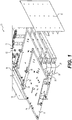
- Figure 1 is a perspective, exploded view of a rack 10 in accordance with an embodiment of the present technology.
- the rack 10 may for example be a 19-inch, standard-size rack having dimensions as defined in the EIA/ECA-310-E "Cabinets, Racks, Panels, And Associated Equipment” standard published by The Electronic Components Sector Of The Electronic Industries Alliance, December 2005 .
- Figure 2 is a perspective, detailed view of the rack 10 of Figure 1 with a partially inserted component in accordance with an embodiment of the present technology.
- Figure 3 is a perspective, detailed view of the rack 10 of Figure 1 with a fully inserted component in accordance with an embodiment of the present technology.
- the rack 10 comprises a backplane 12, a pair of side panels 14, 16 extending from the backplane 12, and support members 18, 20 mounted on each side panel 14, 16.
- Each support member 18, 20 is internal to the rack 10 and adapted to mate with a corresponding side edge 24, 26 of a component 22 that may be inserted in the rack 10.
- the component 22 is made of a main, standard-size board 28 on which a non-standard-size component (shown on later Figures) is mounted.
- the support members 18, 20 mechanically guide an initial alignment of the component 22 upon initial insertion of the component 22 in the rack 10.
- Two male connectors 30, 32 mounted to the backplane 12 are configured to mate with two female connectors 34, 36 supported by a secondary board 38 that, in turn, is mounted to the rear of the standard-size board 28 of the component 22. Mating of two male connectors 30, 32 with the two female connectors 34, 36 helps to mechanically guide a final alignment of the component 22 when the component is further inserted in the rack 10. Though not illustrated, an additional pair of male connectors may be mounted on the backplane 12 and an additional pair of female connectors may be mounted on the secondary board 38, or on another secondary board, for redundancy purposes.
- the two male connectors 30, 32 are defined in a plane parallel to the standard-size board 28 and perpendicular to the side panels 14, 18. Configurations in which two male connectors 30, 32 would be positioned vertically, one above the other, or defining an angle not parallel to a surface of the standard-size board 28, to mate with similarly positioned female connectors 34, 36, are also contemplated.
- the rack 10 defines a plurality of parallel stages 40, each respective stage 40 being adapted for receiving a respective component 22.
- Each respective stage 40 includes respective support members 18, 20 mounted to the side panels 14, 16.
- Each respective support member is internally positioned in the rack 10 and adapted to mate with a corresponding side edge 24, 26 of the respective component 22 to mechanically guide an initial alignment of the respective component 22 upon initial insertion of the respective component 22 in the respective stage 40.
- Each respective stage 40 also includes a respective set of two male connectors 30, 32 mounted in the backplane 12 and configured to mate with two female connectors 34, 36 of the respective component 22 to mechanically guide a final alignment of the respective component 22 when the respective component 22 is further inserted in the rack 10.
- a vertical spacing between each of the plurality of parallel stages 40 may correspond to a standard-size rack unit (RU or "U"), for example having a height of 1.75 inches, as defined in the EIA/ECA-310-E standard.
- the backplane 12 and the side panels 14 and 16 extend vertically and the support members 18, 20 are positioned so that each component 22 can be received in the rack 10 in a horizontal position. While the positioning of the backplane 12, side panels 14, 16 and components 22 complies with the conventional positioning of the EIA/ECA-310-E standard, the present disclosure is not so limited. For example, the side panels 14 and 16 could extend horizontally (becoming upper and lower panels), in which case the components 22 would extend vertically when received in the rack 10.
- Figure 4 is schematic top plan view of the rack 10 of Figure 1 with the partially inserted component 22 in accordance with an embodiment of the present technology.
- Figure 5 is schematic top plan view of the rack 10 of Figure 1 with the fully inserted component 22 in accordance with an embodiment of the present technology.
- one stage 40 is illustrated; it is however understood that the rack 10 may include a plurality of parallel stages 40, as illustrated in Figure 1 , each parallel stage 40 being similarly constructed and including the same or equivalent respective elements as those shown on Figures 5 and 6 .
- Figures 4 and 5 are not to scale. In particular, the size of lateral gaps 42, 44 between the side edges 24, 26 of the standard-size board 28 and internal faces 46, 48 of the side panels 14, 16 are exaggerated for illustration purposes. Relative dimensions of the male connectors 30, 32 and of the female connectors 34, 36 and spacing between the two male connectors 30, 32 or between the two female connectors 34, 36, in view of general dimensions of the rack 10 and of the standard-size board 28, do not necessarily reflect an actual implementation.
- Figures 4 and 5 reproduce several of the elements of Figures 1 , 2 and 3 and further show a non-standard-size component 50 mounted on the standard-size board 28 of the component 22.
- the non-standard-size component 50 may include, without limitation, any electronic device or group of devices (not shown) that perform processing functions, data storage functions, and like functions adapted for the purposes of the rack 10.
- the electronic device or group of devices may be mounted directly on the standard-size board 28.
- the component 22 is connected to a group 60 of electrical components mounted on the backplane 12. The group 60 and its electrical components are illustrated in details in a later Figure. Electrical supply to the component 22 may optionally be made via the male connectors 30, 32 and the female connectors 34, 36.
- a contactor 54 and a contactor 56 that are respectively mounted to the secondary board 38 and to the backplane 12 enable data communication between the component 22 and the group 60 of electrical components.
- the non-standard-size component 50 is connected to the female connectors 34, 36 via electrical leads 52 and connected to the contactor 54 via a data connection 58.
- the electrical leads 52 and/or the data connection 58 may be implemented as wires or may be integrated at least in part within the board 28.
- the female connectors 34, 36 mounted on the component 22 facilitate the alignment of the component 22 when inserted in the rack 10.
- the male connectors 30, 32 and the female connectors 34, 36 may or may not support additional functions or features.
- additional connections between the component 22 and the backplane 12 are provided by fluidic ports for exchange of liquid (e.g. water) for cooling the rack 10 and, in particular but without limitation, for cooling equipment mounted behind the backplane 12.
- These ports include inlet and outlet ports mounted in the backplane 12, as well as feed and return ports that are part of a liquid connector mounted on the component 22.
- the inlet and outlet ports may double as male connectors 30, 32 and the feed and return ports may double as female connectors 34 and 36, in which case no other component may be used to facilitate the alignment of the component 22 in the backplane 12.
- the inlet and outlet ports may be used as substitutes for one of the male connectors 30, 32 and the feed and return ports may be used as substitutes for one of the female connectors 34, 36.
- the liquid connector (including the feed and return ports) is mounted on the component 22 at a distance from another female connector also mounted on the component 22 while the inlet and outlet ports are mounted on the backplane 12 at a distance from another male connector also mounted on the backplane 12.
- other electrical connections are provided between the component 22 and the backplane, as will be described hereinbelow.
- male and female connectors as illustrated in Figures 1 to 5 are present in addition to the liquid connector.
- Figure 6 is a top plan view of a variant of a component 22 insertable in the rack 10 of Figure 1 , the component 22 providing a fluidic connection for cooling purposes.
- Figure 6 illustrates the above-mentioned, non-limiting first embodiment in which the inlet and outlet ports double as male connectors 30, 32 while the feed and return ports double as female connectors 34 and 36.
- a male inlet port 62 and a male outlet port 64 are mounted on a section 66 of the backplane 12.
- the inlet port 62 is connected to a "cold" inlet tube 68 mounted behind the backplane 12 for distributing liquid, for example water, for cooling of equipment mounted in the rack 10.
- the liquid returns to the outlet port 64 via a "hot" outlet tube 70.
- a liquid adaptor 72 is mounted on the component 22, proximally to a rear edge 74 of the component 22.
- the liquid adaptor 72 comprises a female feed port 76, a female return port 78, and an elongate rod 80 that extends at one end between the feed and return ports 76, 78 and at another end to a front of the component 22.
- the feed port 76 and the return port 78 are respectively adapted for mating with the inlet port 62 and with the outlet port 64 when the component 22 is inserted in the rack 10. Operation of the elongate rod 80 is described hereinbelow.
- a "cold" feed tube 82 is connected to the feed port 72 and extends to the front of the component 22.
- a "hot" return tube 84 is connected to the return port 74 and also extends to the front end of the component 22.
- a cooling liquid may be injected via the feed tube 82 and reach the inlet tube the liquid returning to the return tube 84 via the outlet tube 70.
- Figure 7 is a perspective, detailed view of the component 22 of Figure 6 partially inserted in the rack 10 in accordance with an embodiment of the present technology.
- Figure 8 is a perspective, detailed view of the component 22 of Figure 6 being substantially fully inserted in the rack 10 in accordance with an embodiment of the present technology.
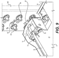
- Figure 9 is a perspective, detailed view of the component 22 of Figure 6 being fully inserted and locked in the rack 10 in accordance with an embodiment of the present technology.
- the various tubes of Figure 6 omitted on Figures 6 to 9 in order to simplify the illustration. Referring at once to Figures 6 to 9 , an inlet port 62 and an outlet port 64 are mounted in each stage 40 on the section 66 of the backplane 12. A slot 86 is formed in each stage 40 of the backplane 12.
- Each slot 86 is proximal to a corresponding inlet port 62 and to a corresponding outlet port 64.
- the slot 86 located on a given stage 40 forms an attachment point for the liquid adaptor 72 located on a component 22 that is on the same stage 40 of the rack 10.
- a center of the inlet port 62, a center of the outlet port 64 and a center of the slot 86 on the same stage 40 generally form a flat triangle.
- the slot 86 may alternatively be positioned between the corresponding inlet and outlet ports 62, 64.
- the elongate rod 80 has lateral extensions 88, such as pins, on an end section 90 of the elongate rod 80 that protrudes beyond the rear edge 74 of the component 22, the feed port 76 and the return port 78.
- the pair formed by the inlet port 62 and the feed port 76 is interchangeable with the pair formed by the outlet port 64 and the return port 78.
- the hot and cold tubes may be connected to any one of the ports as long as consistency is maintained between these connections and a cooling system (not shown) of the rack 10.
- a front end 92 of the elongate rod 80 opposite from the end section 90 is configured for receiving a rotating motion from a connectable handle, a screwdriver, or like tool (not shown).
- the elongate rod 80 is rotated, for example manually, for aligning the lateral extensions 88 with the slot 86 prior to full insertion of the component 22 in the rack 10, substantially as illustrated on Figure 7 .
- Figure 8 shows that the end section 90 and the lateral extensions 88 have been inserted via the slot 86 within the backplane 12.
- the elongate rod 80 has not yet been rotated further from its position on Figure 7 , as evidenced by the orientation of pins 94 that remains unchanged between Figures 7 and 8 .
- Figure 9 shows that the elongate rod 80 is rotated about a quarter of a turn, as evidenced by the different orientation of the pins 94.
- the rotation of the elongate rod 80 places the lateral extensions 88 out of alignment with the slot 86 after full insertion of the component 22 in the rack 10. This causes the lateral extensions 88 to abut on a face (not shown) of the backplane 12 opposite from the component 22 to maintain the liquid adaptor 72 in place.
- This movement is caused by a pressure applied on the liquid connector 72 by the pins 94 when the lateral extensions 88 are slightly pulled inward of the backplane 12 by the rotation of the elongate rod 80, the lateral extensions 88 being forcefully entrained on the face of the backplane 12 opposite from the component 22.
- This movement has at least a double effect, in which the component 22 is held firmly in place in the rack 10 while, in addition, watertight connections are established between the inlet and feed ports 62, 76 and between the outlet and return ports 64, 78.
- seals such as for example TeflonTM or rubber rings may be provided to prevent leakage at the connections between the various ports.
- an embodiment of the rack 10 may include at once the male connectors 30, 32 and the female connectors 34, 36 as illustrated on Figure 1-5 , along with the liquid connector 72 as illustrated on Figure 6 .
- Another embodiment may include a single male connector 30 mounted on the backplane 12 and a single female connector 34 cooperating with the liquid connector 72 and the inlet and outlet ports 62, 64 to provide proper alignment of thee component 22 in the rack 10.
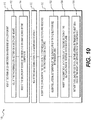
- FIG 10 is a sequence diagram of a method of mounting the non-standard-size component 50 in the rack 10 in accordance with an embodiment of the present technology.
- a sequence 100 comprises a plurality of operations that may be executed in variable order, some of the operations possibly being executed concurrently, some of the operations being optional.
- operation 110 comprises mounting the two female connectors 34, 36 on a rear end of the component 22.
- the two female connectors 34, 36 may be mounted directly on the component 22.
- operation 110 may comprise sub-operation 112 that includes mounting the two female connectors 34, 36 on a secondary board 38, and sub-operation 114 that includes mounting the secondary board 38 at the rear end of the main board 28 of the component 22.
- the two male connectors 30, 32 are mounted on the backplane 12 of the rack 10.
- operation 130 the component 22 is inserted in the rack 10 until the two male connectors 30, 32 are received in the two female connectors 34, 36. If at least one of the two male connectors 30, 32 comprises the inlet and outlet ports 62, 64, in which case a corresponding at least one of the two female connectors 34, 36 comprises the feed and return ports 76, 78, operation 130 may comprise sub-operations 132, 134 and 136. At sub-operation 132, the lateral extensions 88 of the elongate rod 80 are substantially aligned with the slot 86 formed on the backplane 12. At sub-operation 134, the component 22 is inserted in the rack 10 until the end section 90 of the elongate rod 80 is inserted in the backplane 12.
- the elongate rod 80 is rotated for placing the lateral extensions 88 out of alignment with the slot 86 to cause the lateral extensions to abut on the face of the backplane 12 opposite from the component 22 to maintain the component 22 inserted in the rack 10.
- the group 60 of electrical components introduced in the foregoing description of Figures 4 and 5 is illustrated in details on Figure 11 , which is a block diagram showing backplane electrical components 60 of the rack 10 of Figure 1 in accordance with an embodiment of the present technology.
- the group 60 comprises an AC power source 162, DC power source 164, a switch 166, a controller 168 and a protection circuit 170.
- the AC power source 162 is connected to the switch 166 via a line connection 172 and a neutral connection 174.
- the DC power source 164 is connected to the switch 166 via a positive connection 176 and a negative connection 178.
- the switch 166 has two (2) outputs 180 and 182 that are respectively connected via the protection circuit 170 to the male connectors 30, 32.
- the protection circuit 170 includes a sensor 188 of a level of power delivered from the backplane 12 to the component 22 and a breaker 190 operatively connected to the sensor and selectively connecting the switch 166 to the two male connectors 30, 32.
- the sensor 188 may comprise a power meter to directly measure the level of power delivered to the component 22 or an ammeter to measure a current delivered to the component 22.
- the breaker 190 disconnects leads 192, 194 that extend between the outputs 180, 182 of the switch 166 and the male connectors 30, 32 to interrupt the delivery of power to the component 22 when the sensor 188 senses that the power level exceeds a high power threshold or, equivalently, when the sensor 188 senses that the current delivered to the component 22 exceeds a high current threshold.
- the breaker 190 may resume the delivery of power to the component 22 in response to receiving, after interruption of the delivery of power to the component 22, a rearm command 196 from the controller 168.
- an initial contact is established between at least one of the two male connectors 30, 32 and at least one of two female connectors 34, 36. Electrical conductivity between the male and female connectors may be detected and reported to the controller 168.
- the controller 168 may detect an electrical continuity between the male connectors 30, 32, the female connectors 34, 36 and any part of the component 22.
- the at least one of the two male connectors 30, 32 and the at least one of two female connectors 34, 36 may thus form a detector of the initial contact.
- the contactors 54 and 56 come in contact with one another to allow data communication between the non-standard-size component 50 and electrical components in the backplane 12.
- the contactors 54 and 56 may form a detector of a full insertion of the two male connectors 30, 32 in the two female connectors 34, 36.
- the full insertion detected by the contactors 54 and 56 is reported to the controller 168.
- the controller causes the switch 166 to allow either the AC power source 162 or the DC power source 164 to start delivering power to the component 22 inserted in the rack 10 via electrical connections established between the two male connectors 30, 32 and the two female connectors 34, 36 of the component inserted 22 in the rack 10.
- AC or DC power delivery is selected in response to information provided upon detection of the initial contact between the male connectors 30 and 32, and the female connectors 34, 36, or by the contactors 54 and 56, when they detect further insertion of the component 22 in the rack 10.
- a type of the non-standard-size component 50 is detected.
- the controller 168 may read this type via the male connectors 30, 32, the female connectors 34, 36 and the leads 52 connecting the female connectors 34, 36 to the non-standard-size component 50.
- the controller 168 may read this type via the contactors 54, 56 and the data connection 58 between the contactor 54 and the non-standard-size component 50.
- the type may be stored in an electrically-erasable programmable read-only memory (EEPROM) (not shown) mounted on the non-standard-size component 50.
- EEPROM electrically-erasable programmable read-only memory
- these connections allow the controller 168 to determine, based on the detected type, whether the non-standard-size component 50 requires AC or DC power. Also in either variant, these connections allow the controller 168 to read a required polarity of the non-standard-size component 50 when the non-standard-size component 50 requires DC power or identifications of a line input and of a neutral input of the non-standard-size component 50 when the non-standard-size component 50 requires AC power.
- the controller 168 causes the switch 166 to connect one of the two male connectors 30, 32 to the positive connection 176 of the DC power source 164 and to connect the other of the two male connectors 30, 32 to the negative connection 178 of the DC power source 64. Which one of the two male connectors 30, 32 is connected to the positive connection 176 or to the negative connection 178 of the DC power source 164 is selected in view of the required polarity of the non-standard-size component 50.
- the controller 168 causes the switch 166 to connect one of the two male connectors 30, 32 to the line connection 172 of the AC power source 162 and to connect the other of the two male connectors 30, 32 to the neutral connection 174 of the AC power source 162. Which one of the two male connectors 30, 32 is connected to the line connection 172 or to the neutral connection 174 of the AC power source 162 is selected in view of the line and neutral inputs of the non-standard-size component 50.
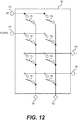
- FIG 12 is a schematic diagram of internal connections of the switch 166 of Figure 11 in accordance with an embodiment of the present technology.
- the switch 166 is controlled by the controller 168 and includes internal commutators 184 that can connect any one of the line connection 172, the neutral connection 174, the positive connection 176 and the negative connection 178 to any one of the outputs 180, 182.
- the controller1 68 or an internal logic of the switch 166 ensures that no unsafe combination of the internal commutators 184 is made within the switch 166.
- FIG 13 is a sequence diagram of a method of mounting a non-standard-size component 50 in the rack 10 in accordance with an embodiment of the present technology.
- a sequence 200 comprises a plurality of operations that may be executed in variable order, some of the operations possibly being executed concurrently, some of the operations being optional.
- operation 210 comprises mounting the non-standard-size component 50 on the standard-size board 28.
- the two female connectors 34, 36 are mounted on a rear end of the standard-size board 28 at operation 220. In this operation 220, the two female connectors 34, 36 may be mounted directly on the standard-size board 28.
- operation 220 may comprise sub-operation 222 comprising mounting the two female connectors 34, 36 on the secondary board 38 and sub-operation 224 comprising mounting the secondary board 38 at the rear end of the standard-size board 28.
- the two male connectors 30, 32 are mounted on the backplane 12 of the rack 10.
- Electrical connections 52 may be provided at operation 240 between the non-standard-size component 50 and each of the two female connectors 34, 36.
- the data connection 58 may be provided between the non-standard-size component 50 and the connector 54 mounted to the standard-size board 28 or to the secondary board 38 at operation 250.
- the standard-size board 28 is inserted in the rack 10 until the two male connectors 30, 32 are received in the two female connectors 34, 36.
- An electrical connection may then be provided between each of the two female connectors 34, 36 and a corresponding one of the two male connectors 30, 32 at operation 270.
- a data connection may be provided between the backplane 12 and the connector 54 mounted to the standard-size board 28 or to the secondary board 38 at operation 280.
- FIG 14 is a sequence diagram of a method of delivering power to a component mounted in a rack in accordance with an embodiment of the present technology.
- a sequence 300 comprises a plurality of operations that may be executed in variable order, some of the operations possibly being executed concurrently, some of the operations being optional.
- operation 310 comprises detecting an initial contact established between at least one of the male connectors 30, 32 mounted to the backplane 12 of the rack 10 and at least one of the female connectors 34, 36 of the component 22. This operation 310 takes place following initial insertion of the component 22 in the rack 10.
- the at least one of the two male connectors 30, 32 and the at least one of the two female connectors 34, 36 are used in detecting the initial contact at operation 310, for example by reporting to the controller 168 a detected electrical continuity between the backplane 12 and the component 22.
- the two male connectors 30, 32 and the two female connectors 34, 36 are sized and configured to mechanically guide an alignment of the component 22 in the rack 10 following the initial contact.
- a full insertion of the two male connectors 30, 32 in the two female connectors 34, 36 is detected at operation 320. Detection of the full insertion may be effected when the contactors 54 and 56 are joined and reported to the controller 168.
- a type of the component 22 inserted in the rack 10, more specifically a type of the non-standard-size component 50, may be detected at operation 330.
- This operation 330 may be omitted, for example, in an embodiment where all components 22 in the rack 10 are of the same type, all of them requiring AC power or DC power.
- AC or DC power is delivered at operation 340 from the backplane 12 to the component 22.
- Power delivery is made via a first electrical connection between a first of the two male connectors 30, 32 and a corresponding first of the two female connectors 34, 36 and via a second electrical connection between a second of the two male connectors 30, 32 and a corresponding second of the two female connectors 34, 36.
- Power delivery from the backplane 12 to the component 22 is in the form of AC power or DC power depending on the detected type of the component 22.
- the first electrical connection is a positive DC voltage connection and the second electrical connection is a DC negative voltage connection when DC power is delivered.
- the first electrical connection is a line AC voltage connection and the second electrical connection is a neutral connection when AC power is delivered.
- the sequence 300 may continue with operation 350 in which a level of power delivered from the backplane 12 to the component 22 is sensed by the sensor 188 of the protection circuit 170.
- the level of power delivered to the component 22 may be sensed directly or calculated based on a sensed current level.
- the delivery of power to the component 22 may be interrupted by the breaker 190 of the protection circuit 170 at operation 360 when the sensed power level exceeds a high power threshold.
- a rearm command 196 may be provided by the controller 168 and received by breaker 190 of the protection circuit 170 at operation 370, after interruption of the delivery of power to the component 22.
- the delivery of power to the component 22 may resume at operation 380 in response to receiving the rearm command 196 at the protection circuit 170.
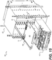
- FIG. 15 is a front perspective view of a system 400 comprising another rack 402 and at least one insertable component 404 in accordance with an embodiment of the present technology.
- FIG. 16 is a front perspective view taken from another angle of the rack 402 of Figure 15 in accordance with an embodiment of the present technology
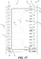
- Figure 17 which is a front elevation view of the rack 402 of Figure 15 in accordance with an embodiment of the present technology
- Figure 18 which is a rear perspective view taken from another angle of the rack 402 of Figure 15 in accordance with an embodiment of the present technology.
- the system 400, the rack 402 and the component 404 integrate several of the elements described in relation to the previous Figures and further incorporate additional elements.
- the component 404 includes the liquid adaptor 72 introduced in the description of Figure 6 .
- the rack 402 includes on its backplane 12 the section 66 adapted for mating with the liquid adaptor 72, as introduced in the description of Figure 6 .
- the component 404 also includes a midplane 406 that connects to the backplane 12 of the rack 402, as will be described in details hereinbelow.
- the midplane 406 is mounted on a main board 408 of the component 404; the midplane 406 may be viewed as another embodiment of the secondary board 38 of earlier Figures.
- the rack 402 comprises a plurality of vertically distributed rack stages that each correspond to a backplane stage 410.
- Each rack stage and corresponding backplane stage 410 is adapted to receive a distinct component such as the component 404.
- the main board 408 may be a standard-size board, for example a 19-inch board.
- Each rack/backplane stage 410, or position, may occupy a standard-size rack unit "U".
- a height of the shown component 404 is adapted to fit in a single rack stage, having a height not exceeding the unit U.
- Each rack stage and the corresponding backplane stage 410 are adapted to receive a distinct component when each of those components has a height that does not exceed the unit U.
- Another component 412 occupies a plurality of backplane stages 410 when inserted in the rack 402.
- a midplane (not shown) of the component 412 connects to at least one backplane stages 410 in the same or equivalent manner as does the midplane 406 of the component 404.
- Some elements of the backplane 12 remain unused in some of the backplane stages 410 that are located behind the component 412.
- the backplane 12 includes a power and data section 414 located at an opposite end of the backplane 12 from the section 66 where the liquid adaptor 72 of the component 404 is connected.
- the power and data section 414 includes a backplane power connector 416 and a backplane data connector 418.
- the backplane power connector 416 is connectable to a component power connector (shown on a later Figure) mounted on the midplane 406 that is, in turn, mounted on the main board 408 of the component 404.
- the backplane data connector 418 is connectable to a component data connector (shown on a later Figure), also mounted on the midplane 406 of the component 404.
- the rack 404 includes a rear section 420 located behind the backplane 12.
- a plurality of ventilators 422 (schematically represented as square boxes on Figure 18 ) is mounted to the backplane 12 and provides cooling ventilation to the system 400 via circular openings 424 formed in the backplane 12.
- the rear section 420 also holds a power panel 426.
- the power panel 426 comprises a plurality of power stages 428. Each power stage 428 of the power panel 426 is electrically connected, for example via wires (not shown), to the backplane power connector 416 of a corresponding backplane stage 410 of the backplane 12.
- FIG 19 is a detailed view of a power connector 430 mounted on the power panel 426.
- the power connector 430 may be, in a non-limiting example, a Molex 0461144120 connector or an equivalent connector.
- Each power connector 430 mounted on the power panel 426 includes, on an input side 442, a phase input 442p and a neutral input 442 N .
- Each power connector 430 also includes, on an output side 444, a phase output 444 P and a neutral output 444 N .
- Each power connector 430 further includes a data port 446.
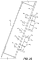
- Figure 20 is a top view of the power panel 426 in accordance with an embodiment of the present technology.
- the system 400 receives power from a sector (not shown) or from uninterruptible power supplies (UPS) (not shown) on two (2) distinct power lines A and B.
- Line A has a phase A connected to a first bus bar 432 and a neutral A connected to a second bus bar 434.
- Line B has a phase B connected to a third bus bar 436 and a neutral B connected to a fourth bus bas 438.
- a fifth bus bar 440 is connected to ground for safety purposes.
- Two (2) complementary power connectors 430 A and 430 B are mounted on each given power stage 428.
- an input side 442 A of the power connector 430 A is connected to the first and second bus bars 432 and 434 to allow a connection of one of the backplane power connectors 416 to phase A and neutral A of the first line via the output side 444 A of the power connector 430 A .
- An input side 442 B of the power connector 430 B is connected to the third and fourth bus bars 436 and 438 to allow a connection the same backplane power connector 416 to phase B and neutral B of the second line via the output side 444 B of the power connector 430 B .
- a total voltage between phases A and B is 230 VAC, +/- 5%.
- the two (2) complementary power connectors 430 of a same power stage 428 of the power panel 426 should be connected a same backplane connector 416 in a corresponding stage 410 of the backplane 12.
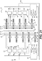
- FIG 21 is a schematic view of the power panel 426 showing how smart breakers 450 are connected thereto in accordance with an embodiment of the present technology.
- a smart breaker is a power control device that is configured to provide power to a component 404 while monitoring the power consumption of that component 404 in order to detect various abnormal conditions, for example overcurrent conditions, short-circuit conditions, and differential current faults.
- Two (2) smart breakers 450 are shown on Figure 21 , one each for the A and B sides of a given power stage 428 of the power panel 426. It should be understood that smart breakers 450 may be connected to each complementary power connector 430 in each power stage 428 of the system 400.
- Each smart breaker 450 comprises a power input 452 connectable to the input side 442 of a power connector 430, a power output side 454 connectable to the output side 444 of the power connector 430, and a data port 456 connectable to the data port 446 of the power connector 430.
- the data port 456 may be in the form of a RS485 connection. Power from one of the lines A or B is received at the power input 452 of the smart breaker 450 via the input side 442 of the power connector 430.
- power may be provided by the power output 454 of the smart breaker 450 to the output side 444 of the power connector 430 and, thereon, to a corresponding backplane power connector 416 of the backplane 12.
- Figure 21 also illustrates other elements of the system 400 that may, in an embodiment, be mounted on the power panel 426. As illustrated, each of these elements is present on both A and B sides of the power panel 426 for redundancy purposes; however, in an embodiment, a single one of each of these elements may be provided.
- One of these elements is a power supply 458 that is electrically connected to one of the lines A or B and that may be used to provide low voltage power, for example DC power, to various processing components of the system 400.
- Another element mounted on the power panel 426 is a main controller 460.
- the main controller 460 receives DC power from the power supply 458.
- the main controller 460 has data connections to the power connectors 430 and further to the smart breakers 450 when these are connected to the power connectors 430.
- An inter-integrated circuit (I C) connection 462 also allows the main controller 460 to communicate with the backplane data connectors 418 on each backplane stage 410 of the backplane 12.
- I C inter-integrated circuit
- a power line communication (PLC) modem 464 is controlled by the main controller 460 and is connected to the phase and neutral of the A or B line.
- a ventilator controller 466 controls turning on or off of the ventilators 422, as directed by the main controller 460.
- the main controllers 460 are connected to each other and to the data ports 446 of the power connectors 430, to the PLC modems 464, and to ventilator controllers 466 via universal asynchronous receiver-transmitter (UART) busses.
- UART universal asynchronous receiver-transmitter
- a non-limiting example of the PLC modems 464 includes Maxim 79356 modems.
- FIG 22 is a high-level schematic circuit diagram of a smart breaker 450 in accordance with an embodiment of the present technology.
- the power input 452 comprises a phase side 452p connectable to the phase input 442p of the power connector 430 and a neutral side 452 N connectable to the neutral input 442 N of the power connector 430.
- the power output 454 comprises a phase side 454p connectable to the phase output 444p of the power connector 430 and a neutral side 454 N connectable to the neutral output 444 N of the power connector 430.
- the smart breaker 450 is capable of detecting a high line current on the A or B phase on which it is connected, the smart breaker 450 being also capable of detecting a differential current fault.
- a sensor 468 senses a line current flowing in the smart breaker 450 via the phase side 452 P of the power input 452.
- Another sensor 470 senses a difference between the line current and a neutral current returning from a load, i.e. from a component 404 mounted in the rack 402 and electrically connected to this smart breaker 450.
- a high line current detector 472 may detect that the sensor 468 reports that the line current is higher than a predetermined threshold and send a signal to a first latch 474.
- a high differential current detector 476 may detect that the sensor 470 reports a differential current that is higher than another predetermined threshold and send another signal to a second latch 478.
- a local controller 480 is informed of the statuses of the first and second latches 474 and 478. The local controller 480 also receives a line current measurement from the sensor 468 and forwards this measurement to the main controller 460 via the data port 456.
- the local controller 480 may receive a rearm signal from the main controller 460 via the data port 456. In response to receiving the rearm signal, the local controller 480 may release the first and second latches 474 and 478, allowing closing of the first and second relays 484 and 486.
- the smart breaker 450 may also be disabled by an action of the main controller 460, for example when the main controller 460 sends a power-off signal to the smart breaker 450.
- the local controller 480 applies by default a disabling signal to the logic combiner 482, causing the opening of the first relay 484.
- the main controller 460 may then send a power-on signal received at the local controller 480, for example when the main controller 460 is informed of the insertion of the component 404 in the backplane stage 410 that corresponds to a location of the smart breaker 450 in the power panel 426.
- the local controller 480 Having received the power-on signal, the local controller 480 sends an enabling signal to the logic combiner 482. As long as the first latch 474 is not set at that time, the logic combiner 482 will cause the closing of the first relay 484. Provided as well that the second latch 478 is not set, power will be available at the power output 454 of the smart breaker 450.
- the main controller 460 sends a presence verification signal, for example a ping signal, to the smart breaker 450 before sending the power-on signal to the smart breaker 450.
- the power-on signal will in that case be provided conditionally to the local controller 480 responding to the main controller with a presence confirmation signal.
- one ventilator controller 466 is powered by the line A and the other ventilator unit is powered by the line B.
- the ventilators 422 are assembled in two (2) ventilator units mounted on the backplane 12 and electrically connected to both sides A and B of the power panel 426.
- the ventilators 422 that are electrically connected to line A are controlled by the ventilator controller 426 that is also powered by the line A.
- the ventilators 422 that are electrically connected to line B are controlled by the ventilator controller 426 that is also powered by the line B.
- Each ventilator unit includes three (3) ventilators 422 in the example of Figures 16 to 18 , although smaller or larger numbers of ventilators 422 may be included in each ventilator unit.
- the ventilator controllers 466 are operatively connected to the main controller 460.
- the main controller 460 is configured to cause the ventilator controllers 466 to turn on the ventilator unit when at least one component 404 is inserted in any backplane stage 410 of the rack 402.
- One ventilator unit may be construed as being redundant to the other ventilator unit.
- the ventilator controllers 466 are configured to cause the ventilators 422 of the ventilator unit and of the redundant ventilator unit to rotate at an intermediate rate, for example 70% of their maximum rate, when all ventilators 422 of the ventilator unit and of the redundant ventilator unit are in operation.
- the ventilator controllers 466 are configured to cause the ventilators 422 of the ventilator unit and of the redundant ventilator unit to rotate at an accelerated rate, for example at their maximum rate, when at least one ventilator 422 of the ventilator unit and of the redundant ventilator unit is not in operation.
- the ventilator controllers may use pulse width modulation (PWM) to control the rotation of the ventilators 422 of the ventilator unit and of the redundant ventilator unit.
- PWM pulse width modulation
- Figure 23 is a front perspective view of a midplane 406 in accordance with an embodiment of the present technology.
- Figure 24 is a rear perspective view of the midplane 406 of Figure 23 in accordance with an embodiment of the present technology.
- Figure 25 is a detailed view of a backplane power connector 416 mounted on a backplane 12.
- Figure 26 is a perspective detailed view showing a connection of the midplane 406 to the backplane 12 in accordance with an embodiment of the present technology.
- Figure 27 is a top plan detailed view showing a connection of the midplane 406 to the backplane 12 in accordance with an embodiment of the present technology.
- the midplane 406 includes a board 488 that supports various active elements and connectors of the midplane 406.
- the midplane 406 includes a component data connector 490 and a component power connector 492.
- the component data connector 490 comes in contact with the backplane data connector 418 of a given backplane stage 410 when the component 404 is inserted in the rack 402.
- the component power connector 492 comes in contact with the backplane power connector 416 of the same backplane stage 410.
- the backplane power connector 416 may, in a non-limiting embodiment, be a Molex 46112-603 connector or an equivalent connector.
- the backplane data connector 418 may be a Molex 76165-3304 or an equivalent connector and the component data connector 490 may be a Molex 76170-3036 connector or an equivalent connector.
- the backplane data connector 418 may include a stud 419 that is insertable in an aperture 491 of the component data connector 490.
- the stud 419 and the aperture 491 facilitate the alignment of the midplane 406 on the data section 414 of the backplane and, further, facilitate the alignment of the component 404 in the rack 402. Jointly with the liquid adaptor 72 and its connection in the section 66 of the backplane 12, the stud 419 and the aperture 491 provide the same or equivalent mechanical alignment features as the male connectors 30, 32 and the female connectors 34, 36 of earlier Figures.
- the component data connector 490 is connected to data plugs 494, for example RJ45 connectors, via internal traces (not shown) within the board 488.
- the component power connector 492 is connected to electric plugs 496 via internal traces (not shown) within the board 488.
- An electronic device mounted on the component 404 for example the non-standard size component 50 introduced in the description of Figures 4 and 5 , may receive power via one or both of the electric plugs 496 and may have data connections to one or more of the data plugs 494.
- the I 2 C connection 462 to the main controller 460 of the power panel 426 reaches the component data connector 490 via the backplane data connector 418 so that the main controller 460 may be placed in contact with the midplane 406.
- the backplane data connector 418 of that backplane stage 410 emits a signal due to the fact that the backplane data connector 418 of that backplane stage 410 becomes connected to the component data connector 490 of the inserted component 404.
- This signal is received by the main controller 460 that thus detects the insertion of the component 404 in the given backplane stage 410 of the rack 402.
- the main controller 460 acquires a set of power parameters of the component 404 via the backplane data connector 418.
- the main controller 460 uses the I 2 C connection 462 to read the set of power parameters from a memory mounted on the midplane 406, for example an EEPROM 540 ( Figure 28 ), via the backplane data connector 418 and via the component data connector 490.
- the main controller 460 then causes the power panel 426 to provide power to the backplane power connector 418 of the backplane stage 410 in which the component 404 is inserted according to the set of power parameters of the component 404.
- the set of power parameters may include, for example an expected power consumption of the component 404 and an indication that the component 404 uses a single or dual power supply.
- EEPROM 540 Other parameters that may be read from the EEPROM 540 include, for example, a name, an IP address and/or a MAC address of a server mounted on the component 404, a serial number of the server, and a height of the component 404 expressed in a number of rack units U.
- the main controller 460 may be connected to each of the power stages 428 of the power panel 426.
- some power connectors 430 that are connected to the bus bars 432 and 434 of line A are directly connected to one main controller 460 and other power connectors 430 that are connected to the bus bars 436 and 438 of line B are directly connected to another main controller 460.
- the two main controllers 460 share the same I 2 C connection 462 so that all power connectors 430 are operatively connected to both main controllers 460.
- the main controller 460 may send a presence verification signal to the smart breaker 450 that is connected to that power stage 428. The main controller 460 may then send a power-on signal to that smart breaker 450 after having received a presence confirmation signal from that smart breaker 450.
- the main controller 460 may cause the power panel 426 to provide power to the backplane power connector 416 of the given backplane stage 410 via one of the complementary power connectors 430 of the power stage 428 corresponding to the given backplane stage 410.
- the main controller 460 may alternatively cause the power panel 426 to provide power to the backplane power connector 416 of the given backplane stage 410 via both of the complementary power connectors 430 of the power stage 428 corresponding to the given backplane stage 410 if the component 404 specifies a dual power supply.
- the main controller 460 is further configured to detect the insertion of each component in these distinct rack/backplane stages 410 and to cause the power panel 426 to independently provide power to each of the distinct components being inserted in the distinct rack/backplane stages 410. Power is supplied to each distinct component according to distinct sets of power parameters of the distinct components acquired via distinct data connectors 418 of distinct rack/backplane stages 410 in which the distinct components are inserted.
- the main controller 460 may obtain, from the smart breakers 450 inserted in each distinct power stage 428, a measurement of a power consumption for each component such as the component 404 inserted in each rack/backplane stage 410.
- the main controller 460 may assemble the distinct power consumption measurements to form a power consumption mapping for the rack and cause the PLC modems 464 to transmit the power consumption mapping over the power lines A and/or B, for example to an operation management center of a datacenter.
- the main controller 460 may assemble operational parameters of all components inserted in the rack 402 in a tabular form as shown in Table I.
- Table I relates to a non-limiting example in which the rack 402 has 16 rack/backplane stages 410 numbered from 0 to 15 and various operational parameters are expressed in 16-bit words.
- Table I Parameter Name Stage 15 Stage 14 .... Stage 0 IsAllowed Yes/No Yes/No ... Yes/No IsInserted Yes/No Yes/No ... Yes/No IsOn Yes/No Yes/No ... Yes/No SmartBreakerA Present/Absent Present/Absent ... Present/Absent SmartBreakerB Present/Absent Present/Absent ...
- the main controller 460 may cause the PLC modems 464 to transmit the power the entire contents of Table I, over the power lines A and/or B, to an operation management center of a datacenter.
- the PLC modems 464 may encrypt the information sent over the power lines A and/or B, for example using the Advanced Encryption Standard (AES) 256.
- AES Advanced Encryption Standard
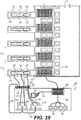
- FIG 28 is a schematic view showing electrical and data connections between the midplane and the backplane in accordance with an embodiment of the present technology.
- Each backplane data connector 416 has five (5) connection points.
- a first connection point 498 is connected by wire (not shown) to a pin 500 ( Figure 21 ) that is in turn connected within the power panel 426 to the phase output 444 P of a power connector 430 of a corresponding power panel stage 428.
- a second connection point 502 is connected to a pin 504 that is in turn connected to the neutral output 444 N .
- a third connection point 506 is connected to a pin 508 that is in turn connected to the phase output 444p of a complementary power connector 430 and a fourth connection point 510 is connected to a pin 512 that is in turn connected to the line output 444 N of the complementary power connector 430. Finally, a fifth connection point 514 is connected to a pin 516 that is connected to the ground bus bar 440.
- One of the electric plugs 496 is connected to line A via internal leads 518 of the board 488 that reach a tab 520 of the component power connector 492, which is adapted to be inserted in a position 522 of the backplane power connector 416, thereby being connected on one side thereof to the pin 498 and on an opposite side to the pin 502 and further to the phase and neutral of line A.
- the other electric plug 496 is connected to line B via internal leads 524 of the board 488 that reach a tab 526 of the component power connector 492, which is adapted to be inserted in a position 528 of the backplane power connector 416, thereby being connected on one side thereof to the pin 506 and on an opposite side to the pin 510 and further to the phase and neutral of line B.
- Both electric plugs 496 have a ground connection connected via internal leads 530 to a tab 532 of the component power connector 492, which is adapted to be inserted in a position 534 of the backplane power connector, thereby being connected to the pin 514 and further to the ground bus bar 440.
- the EEPROM 540 is mounted to the midplane 406, more specifically on the board 488.
- An internal lead 542 of the board 488 links the EEPROM 540 to the component data connector 490.
- the main controller 460 can read information related tot he midplane 406 and to the component 404 from the EEPROM 540.
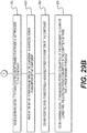
- Figures 29A and 29B is a sequence diagram of a method of providing power to a component received in a rack in accordance with an embodiment of the present technology.
- a sequence 600 comprises a plurality of operations that may be executed in variable order, some of the operations possibly being executed concurrently, some of the operations being optional.
- an insertion of the component 404 in a given stage of the rack 402 is detected by receiving, at the main controller 460 a signal from the backplane data connector 418 of a given backplane stage 410 of the rack 402.
- This insertion of the component 404 in the rack 402 establishes a contact between the backplane data connector 418 in the given rack/backplane stage 410 of the rack 402 and the component data connector 490 of the component 404.
- a set of power parameters of the component 404 is acquired by the main controller 460 via the backplane data connector 418 in the given stage 410 of the rack 402 at operation 620.
- the set of power parameters including for example an expected power consumption of the component 404 and an indication that the component 404 uses a single or dual power supply, may be obtained from the EEPROM 540.
- EEPROM 540 Other parameters that may be read from the EEPROM 540 include, for example, a name, an IPv6 and/or an IPv4 address, and a MAC address of a server mounted on the component 404. Another parameter that may be read from the EEPROM 540 indicates whether the component 404 occupies one or more of the rack/backplane stages 410 of the rack 402, the height of the component being expressed in a number of rack units U.
- a parameter read from the EEPROM 540 may indicate to the main controller 460 that a first, lowest position within four (4) rack/backplane stages 410 occupied by the component 412 may have a component power connector 492 and that other positions occupied by the component 412 do not include any component power connector 492. It would not be useful in such a case to mount smart breakers 450 in corresponding second, third and fourth power stages 428 of the power panel 426. If smart breakers 450 are nevertheless mounted in all power stages 428 of the power panel 426, it would not be useful in the same example to energize the smart breakers 450 connected to the second, third and fourth power stages 428 of the power panel.
- the power panel 426 is caused to provide power to the backplane power connector 416 in the given stage 410 of the rack 402, the power being provided in accordance to the set of power parameters of the component 404. For example, depending on the dual or single power supply specification provided by the EEPROM 540, power may become available on one or both of the electric plugs 496. In a single power supply case, the main controller 460 may energize a single one of the smart breakers 450 connected to the two (2) complementary power connectors 430.
- operation 630 may comprise sub-operations 632, 634 and 636.
- the main controller 460 sends a presence verification signal, for example a ping signal, to the smart breaker 450 connected to the given power stage 428 of the power panel 426 that is electrically connected to the backplane power connector 416 in the given stage 410 of the rack 402.
- the local controller 480 receives this presence verification signal.
- the main controller 460 receives a presence confirmation signal from the local controller 480 of the smart breaker 450 at sub-operation 634.
- the main controller 460 sends a power-on signal to the smart breaker 450.
- the power-on signal is also received by the local controller 480 that, in turn, provides an enabling signal to the logic combiner 482, causing the first relay 484 to close.
- the first latch 474 is not expected to be set given that given that the smart breaker 450 was inactive until that time.
- the second latch 478 is not expected to be set and the second relay 486 is expected to be closed.
- a warning signal may be issued at operation 640 if the main controller 460 determines that power is not provided to the component 404, for example if the main controller 460 does not receive the presence confirmation signal from local controller 480 of the smart breaker 450 or if the smart breaker 450 detects that the component 404 does not consume any power.
- the main controller 450 may read an expected power consumption of the component 404 in the set of power parameters of the component 404 obtained from the EEPROM 540.
- a measured power consumption of the component 404 may be obtained at the main controller 460 from the given power stage 428 at operation 660.
- operation 660 may take place following a predetermined delay after the provision of power to the backplane power connector 416 in the given stage 410 of the rack 402 at operation 630.
- This optional delay allows to measure a stabilized power consumption of the component 404.
- it is the local controller 480 of the smart breaker 450 inserted in the given power stage 480 that provides the power consumption measurement of the component 404 based on a current measurement obtained from the sensor 468.
- the main controller 460 may issue another warning signal if the measured power consumption of the component 404 is higher or lower than the expected power consumption of the component 404 by more than a predetermined threshold.
- Another warning signal may be issued by the main controller 460 if the component 404 specifies a dual power supply and if only one of the electric plugs 496 is energized through, for example, the inactivation of one of the smart breakers 450 in the related power stage 428.
- the main controller 460 may cause any one of these warning signals may be issued over the power line A and/or over the power line B using the PLC modems 464 and the PLC protocol.
- the warnings may be received at an operation management center (not shown) of a datacenter in which the system 400 is installed.
Landscapes
- Engineering & Computer Science (AREA)
- Microelectronics & Electronic Packaging (AREA)
- General Engineering & Computer Science (AREA)
- Computer Hardware Design (AREA)
- Power Engineering (AREA)
- Theoretical Computer Science (AREA)
- Physics & Mathematics (AREA)
- Computer Networks & Wireless Communication (AREA)
- General Physics & Mathematics (AREA)
- Thermal Sciences (AREA)
- Cooling Or The Like Of Electrical Apparatus (AREA)
- Mounting Of Printed Circuit Boards And The Like (AREA)
Description
- The present technology relates to enclosures adapted to receive and provide power to electronic equipment. In particular, a rack adapted for receiving a component, a system including the rack and the component and a method of delivering power to a component mounted in a rack are disclosed.
- Electronic devices, for example servers, memory banks, computer discs, and the like, are conventionally mounted one above the other in equipment racks. Some components, for example motherboards, have non-standard form factors and are smaller than conventional rack components. These components cannot be mounted in standard racks without proper adaptation. Various cables are connected to each component inserted in a rack. Some cables carry input and/or output data and signalling. Other cables provide electrical power to the components, in AC or DC form, according to the needs of a particular component. Conventionally, these cables are mounted on the front of the rack, i.e. on the front of the components. In a large rack, the number of cables may be high and lead to potential installation errors or maintenance errors.
- These problems are particularly significant in large data centers that may contain thousands or even tens of thousands of servers. New servers may be added on a daily basis. Some servers may fail and need to be replaced from time to time. Complex cabling, variability of power requirements and variability of component sizes cause difficulties in the provisioning and maintenance of large data centers. Installation and removal of components in equipment racks is a daily routine task for operators. Care must be taken to properly align components within equipment racks. When installed in haste, components may be improperly aligned in their racks, leading to equipment failure or to bad electrical and/or data connections. Consequently, installation of components in equipment racks is a delicate and time-consuming operation.
- The racks, including equipment mounted in their backplanes, consume large amounts of electric power and generate significant amounts of heat. Cooling needs are important in such racks. Water-cooling may be used, but is difficult to provision in an efficient way. The need for hydraulic connections to be fully watertight is self-evident given the presence of electronic equipment.
- Improvements are still desirable in the maintenance and provisioning of large data centers.
- The subject matter discussed in the background section should not be assumed to be prior art merely as a result of its mention in the background section. Similarly, a problem mentioned in the background section or associated with the subject matter of the background section should not be assumed to have been previously recognized in the prior art. The subject matter in the background section merely represents different approaches.
-
US 2011/0289327 A1 discloses a fixed chassis power budget being dynamically allocated to a plurality of servers inserted into a multi-server chassis. An inserted server is inventoried by sequentially identifying server components, categorically-defined component power limits, and actual component power requirements of the inventoried components. A power permission is granted to the inserted server prior to completion of the inventory, based on power-related information inferred from a chassis and server specification or from the inventoried components. -
US 2014/0277784 A1 discloses a rack management method and system. The presence of a computing device releasably mounted in a frame is detected based on an electrical connection established between a configuration bar disposed in a rear portion of the frame and the computing device. A physical location of the computing device within the frame is determined based on the electrical connection. Management information about the computing device is retrieved from a profile storage disposed within the computing device via the electrical connection. The management information is stored in a management table that associates the computing device with the physical location within the frame. - Embodiments of the present technology have been developed based on developers' appreciation of shortcomings associated with the prior art.
- In particular, such shortcomings may comprise (1) cabling complexity, (2) variability of electrical power requirements, and/or (3) variability of component form factors.
- The object of the invention is solved by a rack according to
claim 1 and a method according toclaim 10. Preferred embodiments are presented in the dependent claims. - In the context of the present specification, unless expressly provided otherwise, a computer system may refer, but is not limited to, an "electronic device", an "operation system", a "system", a "computer-based system", a "controller unit", a "monitoring device", a "control device" and/or any combination thereof appropriate to the relevant task at hand.
- In the context of the present specification, unless expressly provided otherwise, the expression "computer-readable medium" and "memory" are intended to include media of any nature and kind whatsoever, non-limiting examples of which include RAM, ROM, disks (CD-ROMs, DVDs, floppy disks, hard disk drives, etc.), USB keys, flash memory cards, solid state-drives, and tape drives. Still in the context of the present specification, "a" computer-readable medium and "the" computer-readable medium should not be construed as being the same computer-readable medium. To the contrary, and whenever appropriate, "a" computer-readable medium and "the" computer-readable medium may also be construed as a first computer-readable medium and a second computer-readable medium.
- In the context of the present specification, unless expressly provided otherwise, the words "first", "second", "third", etc. have been used as adjectives only for the purpose of allowing for distinction between the nouns that they modify from one another, and not for the purpose of describing any particular relationship between those nouns.
- Implementations of the present technology each have at least one of the above-mentioned object and/or aspects, but do not necessarily have all of them. It should be understood that some aspects of the present technology that have resulted from attempting to attain the above-mentioned object may not satisfy this object and/or may satisfy other objects not specifically recited herein.
- Additional and/or alternative features, aspects and advantages of implementations of the present technology will become apparent from the following description, the accompanying drawings and the appended claims.
- For a better understanding of the present technology, as well as other aspects and further features thereof, reference is made to the following description which is to be used in conjunction with the accompanying drawings, where:
-
Figure 1 is a perspective, exploded view of a rack in accordance with an embodiment of the present technology; -
Figure 2 is a perspective, detailed view of the rack ofFigure 1 with a partially inserted component in accordance with an embodiment of the present technology; -
Figure 3 is a perspective, detailed view of the rack ofFigure 1 with a fully inserted component in accordance with an embodiment of the present technology; -
Figure 4 is schematic top plan view of the rack ofFigure 1 with a partially inserted component in accordance with an embodiment of the present technology; -
Figure 5 is schematic top plan view of the rack ofFigure 1 with a fully inserted component in accordance with an embodiment of the present technology; -
Figure 6 is a top plan view of a variant of a component insertable in the rack ofFigure 1 , the component providing a fluidic connection for cooling purposes; -
Figure 7 is a perspective, detailed view of the component ofFigure 6 partially inserted in a rack in accordance with an embodiment of the present technology; -
Figure 8 is a perspective, detailed view of the component ofFigure 6 being substantially fully inserted in the rack in accordance with an embodiment of the present technology; -
Figure 9 is a perspective, detailed view of the component ofFigure 6 being fully inserted and locked in the rack in accordance with an embodiment of the present technology; -
Figure 10 is a sequence diagram of a method of mounting a component in a rack in accordance with an embodiment of the present technology; -
Figure 11 is a block diagram showing backplane electrical components of the rack ofFigure 1 in accordance with an embodiment of the present technology; -
Figure 12 is a schematic diagram of internal connections of the switch ofFigure 11 in accordance with an embodiment of the present technology; -
Figure 13 is a sequence diagram of a method of mounting a non-standard-size component in a in accordance with an embodiment of the present technology; -
Figure 14 is a sequence diagram of a method of delivering power to a component mounted in a rack in accordance with an embodiment of the present technology; -
Figure 15 is a front perspective view of a system comprising another rack and at least one insertable component in accordance with an embodiment of the present technology; -
Figure 16 is a front perspective view taken from another angle of the rack ofFigure 15 in accordance with an embodiment of the present technology; -
Figure 17 is a front elevation view of the rack ofFigure 15 in accordance with an embodiment of the present technology; -
Figure 18 is a rear perspective view taken from another angle of the rack ofFigure 15 in accordance with an embodiment of the present technology; -
Figure 19 is a detailed view of a connector mounted on a power panel; -
Figure 20 is a top view of the power panel in accordance with an embodiment of the present technology; -
Figure 21 is a schematic view of the power panel showing how smart breakers are connected thereto in accordance with an embodiment of the present technology; -
Figure 22 is a high-level schematic circuit diagram of a smart breaker in accordance with an embodiment of the present technology; -
Figure 23 is a front perspective view of a midplane in accordance with an embodiment of the present technology; -
Figure 24 is a rear perspective view of the midplane ofFigure 23 in accordance with an embodiment of the present technology; -
Figure 25 is a detailed view of a backplane power connector mounted on a backplane; -
Figure 26 is a perspective detailed view showing a connection of the midplane to the backplane in accordance with an embodiment of the present technology; -
Figure 27 is a top plan detailed view showing a connection of the midplane to the backplane in accordance with an embodiment of the present technology; -
Figure 28 is a schematic view showing electrical and data connections between the midplane and the backplane in accordance with an embodiment of the present technology; and -
Figures 29A and29B is a sequence diagram of a method of providing power to a component received in a rack in accordance with an embodiment of the present technology; - It should also be noted that, unless otherwise explicitly specified herein, the drawings are not to scale.
- The examples and conditional language recited herein are principally intended to aid the reader in understanding the principles of the present technology and not to limit its scope to such specifically recited examples and conditions. The scope of the invention is defined by the appended claims.
- Furthermore, as an aid to understanding, the following description may describe relatively simplified implementations of the present technology. As persons skilled in the art would understand, various implementations of the present technology may be of a greater complexity.
- In some cases, what are believed to be helpful examples of modifications to the present technology may also be set forth. This is done merely as an aid to understanding, and, again, not to define the scope or set forth the bounds of the present technology. These modifications are not an exhaustive list, and a person skilled in the art may make other modifications while nonetheless remaining within the scope of the present technology. Further, where no examples of modifications have been set forth, it should not be interpreted that no modifications are possible and/or that what is described is the sole manner of implementing that element of the present technology.
- Moreover, all statements herein reciting principles, aspects, and implementations of the present technology, as well as specific examples thereof, are intended to encompass both structural and functional equivalents thereof, whether they are currently known or developed in the future. Thus, for example, it will be appreciated by those skilled in the art that any block diagrams herein represent conceptual views of illustrative circuitry embodying the principles of the present technology. Similarly, it will be appreciated that any flowcharts, flow diagrams, state transition diagrams, pseudo-code, and the like represent various processes that may be substantially represented in computer-readable media and so executed by a computer or processor, whether or not such computer or processor is explicitly shown.
- The functions of the various elements shown in the figures, including any functional block labeled as a "processor", may be provided through the use of dedicated hardware as well as hardware capable of executing software in association with appropriate software. When provided by a processor, the functions may be provided by a single dedicated processor, by a single shared processor, or by a plurality of individual processors, some of which may be shared. In some embodiments of the present technology, the processor may be a general-purpose processor, such as a central processing unit (CPU) or a processor dedicated to a specific purpose, such as a digital signal processor (DSP). Moreover, explicit use of the term a "processor" should not be construed to refer exclusively to hardware capable of executing software, and may implicitly include, without limitation, application specific integrated circuit (ASIC), field programmable gate array (FPGA), read-only memory (ROM) for storing software, random access memory (RAM), and non-volatile storage. Other hardware, conventional and/or custom, may also be included.
- Software modules, or simply modules which are implied to be software, may be represented herein as any combination of flowchart elements or other elements indicating performance of process steps and/or textual description. Such modules may be executed by hardware that is expressly or implicitly shown. Moreover, it should be understood that module may include for example, but without being limitative, computer program logic, computer program instructions, software, stack, firmware, hardware circuitry or a combination thereof which provides the required capabilities.
- With these fundamentals in place, we will now consider some non-limiting examples to illustrate various implementations of aspects of the present technology.
- The present technology allows to efficiently mount equipment in a rack, including without limitation servers, data storage solutions, and the like. In at least one variant, fluidic connections may be included for the provision of liquid cooling. The present technology also allows to electrically connect, to protect, to monitor and to provide network connectivity to various types of equipment mounted in such racks. Power line communication (PLC) capabilities may also be provided to the equipment mounted in the rack.
- In one aspect, the present technology introduces a component insertable in a rack that includes a pair of female connectors that come in alignment with a pair of male connectors located in the backplane of the rack when the component is inserted. Small components having non-standard form factors are mounted on conventionally sized boards that provide interconnection between the small components and the male connectors as well as with any component located beyond the rack. The rack includes mechanical guides to generally locate the insertable components. The female connectors of a given insertable component and the male connectors in the backplane of the rack are positioned so that, in a first time when the given component is at least partially inserted in the rack and the rear end of the given component is placed near the backplane, precise mechanical alignment of the given component is provided by partial and then full insertion of the male connectors in the female connectors.
- In a second time, when the given component is fully inserted in the rack, the male connectors being fully inserted in the female connectors, AC or DC power is delivered to the given component via the connection between the male and female connectors. Electrical power is delivered via the backplane of the rack where the male connectors are located so the number of cables mounted at the front of the rack is reduced.
- In an embodiment, a plurality of pairs of male connectors are mounted in the backplane, each pair being vertically separated from a next pair by a typical height of the insertable components so that plural insertable components can be received in this manner in the rack and are powered in this manner. External logic may control initiation of the AC or DC power provision to the inserted components. Both AC and DC power can be supported in the same rack. The external logic may receive measurements (voltages, current, power, power phase) for the rack in view of providing statistical information about power consumption. It becomes possible to plan the evolution of power consumption as numerous racks and components are added. More male/female connectors may be used, for example for redundancy purposes.
- In the same or another embodiment, fluidic connections for the supply of liquid cooling in the backplane of the rack are provided. In addition to the above described rack and component, a liquid adaptor is mounted on the component. The liquid adaptor includes a feed port and a return port that are respectively meant for mating with an inlet port and an outlet port in the backplane of the rack. An elongate rod part of the liquid adaptor has an end section that penetrates in a slot of the backplane. Rotating the elongate rod locks the component in place against the backplane, within the rack. In a variant, the inlet and outlet ports may supplement the male adaptors and the feed and return ports may be provided in addition to the female adaptors. In another variant, the inlet and outlet ports may form one or both of the male adaptors and the feed and return ports may form one or both of the female adaptors.
- Another embodiment that may or may not integrate some of the above-described embodiments comprises a rack having a backplane, a power panel and a main controller. The backplane has a plurality of stages that each includes a power connector and a data connector. A component may be received in a stage of the rack so that its own power and data connectors come in contact with the power and data connectors of the corresponding backplane stage. The main controller is informed of the insertion of the component by the data connector of the backplane. The main controller also receives a set of power parameters of the component from the data connector of the backplane. The main controller causes the power panel to provide power to the backplane power connector of the backplane stage according to the set of power parameters of the component.
- In the present specification, the term rack should be understood as synonymous with enclosure, chassis, cabinet and similar terms. The term system may encompass a combination of elements, including without limitation a rack and a component inserted in the rack.
- Referring now to the drawings,
Figure 1 is a perspective, exploded view of arack 10 in accordance with an embodiment of the present technology. Therack 10 may for example be a 19-inch, standard-size rack having dimensions as defined in the EIA/ECA-310-E "Cabinets, Racks, Panels, And Associated Equipment" standard published by The Electronic Components Sector Of The Electronic Industries Alliance, December 2005.Figure 2 is a perspective, detailed view of therack 10 ofFigure 1 with a partially inserted component in accordance with an embodiment of the present technology.Figure 3 is a perspective, detailed view of therack 10 ofFigure 1 with a fully inserted component in accordance with an embodiment of the present technology. Referring at once toFigures 1 ,2 and3 , therack 10 comprises abackplane 12, a pair ofside panels backplane 12, andsupport members side panel support member rack 10 and adapted to mate with acorresponding side edge component 22 that may be inserted in therack 10. Thecomponent 22 is made of a main, standard-size board 28 on which a non-standard-size component (shown on later Figures) is mounted. Thesupport members component 22 upon initial insertion of thecomponent 22 in therack 10. Twomale connectors backplane 12 are configured to mate with twofemale connectors secondary board 38 that, in turn, is mounted to the rear of the standard-size board 28 of thecomponent 22. Mating of twomale connectors female connectors component 22 when the component is further inserted in therack 10. Though not illustrated, an additional pair of male connectors may be mounted on thebackplane 12 and an additional pair of female connectors may be mounted on thesecondary board 38, or on another secondary board, for redundancy purposes. - As illustrated, the two
male connectors size board 28 and perpendicular to theside panels male connectors size board 28, to mate with similarly positionedfemale connectors Figure 1 , therack 10 defines a plurality ofparallel stages 40, eachrespective stage 40 being adapted for receiving arespective component 22. Eachrespective stage 40 includesrespective support members side panels rack 10 and adapted to mate with acorresponding side edge respective component 22 to mechanically guide an initial alignment of therespective component 22 upon initial insertion of therespective component 22 in therespective stage 40. Eachrespective stage 40 also includes a respective set of twomale connectors backplane 12 and configured to mate with twofemale connectors respective component 22 to mechanically guide a final alignment of therespective component 22 when therespective component 22 is further inserted in therack 10. Without limitation, a vertical spacing between each of the plurality ofparallel stages 40 may correspond to a standard-size rack unit (RU or "U"), for example having a height of 1.75 inches, as defined in the EIA/ECA-310-E standard. - The
backplane 12 and theside panels support members component 22 can be received in therack 10 in a horizontal position. While the positioning of thebackplane 12,side panels components 22 complies with the conventional positioning of the EIA/ECA-310-E standard, the present disclosure is not so limited. For example, theside panels components 22 would extend vertically when received in therack 10. -
Figure 4 is schematic top plan view of therack 10 ofFigure 1 with the partially insertedcomponent 22 in accordance with an embodiment of the present technology.Figure 5 is schematic top plan view of therack 10 ofFigure 1 with the fully insertedcomponent 22 in accordance with an embodiment of the present technology. Referring at once toFigures 4 and5 , onestage 40 is illustrated; it is however understood that therack 10 may include a plurality ofparallel stages 40, as illustrated inFigure 1 , eachparallel stage 40 being similarly constructed and including the same or equivalent respective elements as those shown onFigures 5 and6 . -
Figures 4 and5 are not to scale. In particular, the size oflateral gaps size board 28 andinternal faces side panels male connectors female connectors male connectors female connectors rack 10 and of the standard-size board 28, do not necessarily reflect an actual implementation. -
Figures 4 and5 reproduce several of the elements ofFigures 1 ,2 and3 and further show a non-standard-size component 50 mounted on the standard-size board 28 of thecomponent 22. The non-standard-size component 50 may include, without limitation, any electronic device or group of devices (not shown) that perform processing functions, data storage functions, and like functions adapted for the purposes of therack 10. In some embodiments, the electronic device or group of devices may be mounted directly on the standard-size board 28. In an embodiment of the present technology, thecomponent 22 is connected to agroup 60 of electrical components mounted on thebackplane 12. Thegroup 60 and its electrical components are illustrated in details in a later Figure. Electrical supply to thecomponent 22 may optionally be made via themale connectors female connectors contactor 54 and acontactor 56 that are respectively mounted to thesecondary board 38 and to thebackplane 12 enable data communication between thecomponent 22 and thegroup 60 of electrical components. In this embodiment, the non-standard-size component 50 is connected to thefemale connectors electrical leads 52 and connected to thecontactor 54 via adata connection 58. The electrical leads 52 and/or thedata connection 58 may be implemented as wires or may be integrated at least in part within theboard 28. - In the embodiment of
Figures 1 to 5 , thefemale connectors male connectors backplane 12 facilitate the alignment of thecomponent 22 when inserted in therack 10. Themale connectors female connectors component 22 and thebackplane 12 are provided by fluidic ports for exchange of liquid (e.g. water) for cooling therack 10 and, in particular but without limitation, for cooling equipment mounted behind thebackplane 12. These ports include inlet and outlet ports mounted in thebackplane 12, as well as feed and return ports that are part of a liquid connector mounted on thecomponent 22. - In a first embodiment, the inlet and outlet ports may double as
male connectors female connectors component 22 in thebackplane 12. In a second embodiment, the inlet and outlet ports may be used as substitutes for one of themale connectors female connectors component 22 at a distance from another female connector also mounted on thecomponent 22 while the inlet and outlet ports are mounted on thebackplane 12 at a distance from another male connector also mounted on thebackplane 12. In these first and second embodiments, other electrical connections are provided between thecomponent 22 and the backplane, as will be described hereinbelow. In a third embodiment, male and female connectors as illustrated inFigures 1 to 5 are present in addition to the liquid connector. -
Figure 6 is a top plan view of a variant of acomponent 22 insertable in therack 10 ofFigure 1 , thecomponent 22 providing a fluidic connection for cooling purposes.Figure 6 illustrates the above-mentioned, non-limiting first embodiment in which the inlet and outlet ports double asmale connectors female connectors male inlet port 62 and amale outlet port 64 are mounted on asection 66 of thebackplane 12. Theinlet port 62 is connected to a "cold"inlet tube 68 mounted behind thebackplane 12 for distributing liquid, for example water, for cooling of equipment mounted in therack 10. The liquid returns to theoutlet port 64 via a "hot"outlet tube 70. Aliquid adaptor 72 is mounted on thecomponent 22, proximally to arear edge 74 of thecomponent 22. Theliquid adaptor 72 comprises afemale feed port 76, afemale return port 78, and anelongate rod 80 that extends at one end between the feed and returnports component 22. Thefeed port 76 and thereturn port 78 are respectively adapted for mating with theinlet port 62 and with theoutlet port 64 when thecomponent 22 is inserted in therack 10. Operation of theelongate rod 80 is described hereinbelow. A "cold"feed tube 82 is connected to thefeed port 72 and extends to the front of thecomponent 22. A "hot"return tube 84 is connected to thereturn port 74 and also extends to the front end of thecomponent 22. When thecomponent 22 is fully installed, a cooling liquid may be injected via thefeed tube 82 and reach the inlet tube the liquid returning to thereturn tube 84 via theoutlet tube 70. 68 -
Figure 7 is a perspective, detailed view of thecomponent 22 ofFigure 6 partially inserted in therack 10 in accordance with an embodiment of the present technology.Figure 8 is a perspective, detailed view of thecomponent 22 ofFigure 6 being substantially fully inserted in therack 10 in accordance with an embodiment of the present technology.Figure 9 is a perspective, detailed view of thecomponent 22 ofFigure 6 being fully inserted and locked in therack 10 in accordance with an embodiment of the present technology. The various tubes ofFigure 6 omitted onFigures 6 to 9 in order to simplify the illustration. Referring at once toFigures 6 to 9 , aninlet port 62 and anoutlet port 64 are mounted in eachstage 40 on thesection 66 of thebackplane 12. Aslot 86 is formed in eachstage 40 of thebackplane 12. Eachslot 86 is proximal to acorresponding inlet port 62 and to acorresponding outlet port 64. Theslot 86 located on a givenstage 40 forms an attachment point for theliquid adaptor 72 located on acomponent 22 that is on thesame stage 40 of therack 10. As illustrated, a center of theinlet port 62, a center of theoutlet port 64 and a center of theslot 86 on thesame stage 40 generally form a flat triangle. Theslot 86 may alternatively be positioned between the corresponding inlet andoutlet ports elongate rod 80 haslateral extensions 88, such as pins, on anend section 90 of theelongate rod 80 that protrudes beyond therear edge 74 of thecomponent 22, thefeed port 76 and thereturn port 78. - It may be noted that the pair formed by the
inlet port 62 and thefeed port 76 is interchangeable with the pair formed by theoutlet port 64 and thereturn port 78. In fact, the hot and cold tubes may be connected to any one of the ports as long as consistency is maintained between these connections and a cooling system (not shown) of therack 10. - A
front end 92 of theelongate rod 80 opposite from theend section 90 is configured for receiving a rotating motion from a connectable handle, a screwdriver, or like tool (not shown). Theelongate rod 80 is rotated, for example manually, for aligning thelateral extensions 88 with theslot 86 prior to full insertion of thecomponent 22 in therack 10, substantially as illustrated onFigure 7 .Figure 8 shows that theend section 90 and thelateral extensions 88 have been inserted via theslot 86 within thebackplane 12. Theelongate rod 80 has not yet been rotated further from its position onFigure 7 , as evidenced by the orientation ofpins 94 that remains unchanged betweenFigures 7 and8 .Figure 9 shows that theelongate rod 80 is rotated about a quarter of a turn, as evidenced by the different orientation of thepins 94. The rotation of theelongate rod 80 places thelateral extensions 88 out of alignment with theslot 86 after full insertion of thecomponent 22 in therack 10. This causes thelateral extensions 88 to abut on a face (not shown) of thebackplane 12 opposite from thecomponent 22 to maintain theliquid adaptor 72 in place. There may be a slight movement of thecomponent 22 in relation to thebackplane 12 betweenFigures 8 and9 , theliquid connector 72 and therear edge 74 of thecomponent 22 being brought slightly closer to thebackplane 12 onFigure 9 . This movement is caused by a pressure applied on theliquid connector 72 by thepins 94 when thelateral extensions 88 are slightly pulled inward of thebackplane 12 by the rotation of theelongate rod 80, thelateral extensions 88 being forcefully entrained on the face of thebackplane 12 opposite from thecomponent 22. This movement has at least a double effect, in which thecomponent 22 is held firmly in place in therack 10 while, in addition, watertight connections are established between the inlet and feedports ports - In some applications, the connections of the female feed and return
ports liquid connector 72 to the male inlet andoutlet ports section 66 of thebackplane 12 may suffice to provide proper alignment of thecomponent 22 in therack 10. Alternatively, an embodiment of therack 10 may include at once themale connectors female connectors Figure 1-5 , along with theliquid connector 72 as illustrated onFigure 6 . Another embodiment may include a singlemale connector 30 mounted on thebackplane 12 and a singlefemale connector 34 cooperating with theliquid connector 72 and the inlet andoutlet ports thee component 22 in therack 10. -
Figure 10 is a sequence diagram of a method of mounting the non-standard-size component 50 in therack 10 in accordance with an embodiment of the present technology. OnFigure 10 , asequence 100 comprises a plurality of operations that may be executed in variable order, some of the operations possibly being executed concurrently, some of the operations being optional. In thesequence 100,operation 110 comprises mounting the twofemale connectors component 22. In thisoperation 110, the twofemale connectors component 22. Alternatively,operation 110 may comprise sub-operation 112 that includes mounting the twofemale connectors secondary board 38, andsub-operation 114 that includes mounting thesecondary board 38 at the rear end of themain board 28 of thecomponent 22. Atoperation 120, the twomale connectors backplane 12 of therack 10. - At
operation 130, thecomponent 22 is inserted in therack 10 until the twomale connectors female connectors male connectors outlet ports female connectors ports operation 130 may comprisesub-operations sub-operation 132, thelateral extensions 88 of theelongate rod 80 are substantially aligned with theslot 86 formed on thebackplane 12. Atsub-operation 134, thecomponent 22 is inserted in therack 10 until theend section 90 of theelongate rod 80 is inserted in thebackplane 12. Atsub-operation 136, after full insertion of thecomponent 22 in therack 10, theelongate rod 80 is rotated for placing thelateral extensions 88 out of alignment with theslot 86 to cause the lateral extensions to abut on the face of thebackplane 12 opposite from thecomponent 22 to maintain thecomponent 22 inserted in therack 10. - The
group 60 of electrical components introduced in the foregoing description ofFigures 4 and5 is illustrated in details onFigure 11 , which is a block diagram showing backplaneelectrical components 60 of therack 10 ofFigure 1 in accordance with an embodiment of the present technology. Thegroup 60 comprises anAC power source 162,DC power source 164, aswitch 166, acontroller 168 and aprotection circuit 170. TheAC power source 162 is connected to theswitch 166 via aline connection 172 and aneutral connection 174. TheDC power source 164 is connected to theswitch 166 via apositive connection 176 and anegative connection 178. Theswitch 166 has two (2) outputs 180 and 182 that are respectively connected via theprotection circuit 170 to themale connectors - The
protection circuit 170 includes asensor 188 of a level of power delivered from thebackplane 12 to thecomponent 22 and abreaker 190 operatively connected to the sensor and selectively connecting theswitch 166 to the twomale connectors sensor 188 may comprise a power meter to directly measure the level of power delivered to thecomponent 22 or an ammeter to measure a current delivered to thecomponent 22. Thebreaker 190 disconnects leads 192, 194 that extend between theoutputs switch 166 and themale connectors component 22 when thesensor 188 senses that the power level exceeds a high power threshold or, equivalently, when thesensor 188 senses that the current delivered to thecomponent 22 exceeds a high current threshold. Thebreaker 190 may resume the delivery of power to thecomponent 22 in response to receiving, after interruption of the delivery of power to thecomponent 22, a rearmcommand 196 from thecontroller 168. - In an embodiment, when the
component 22 is partially inserted in therack 10, an initial contact is established between at least one of the twomale connectors female connectors controller 168. Thecontroller 168 may detect an electrical continuity between themale connectors female connectors component 22. The at least one of the twomale connectors female connectors component 22 is fully inserted in therack 10, thecontactors size component 50 and electrical components in thebackplane 12. As thecontactors male connectors female connectors contactors controller 168. In response to the detection of the full insertion, the controller causes theswitch 166 to allow either theAC power source 162 or theDC power source 164 to start delivering power to thecomponent 22 inserted in therack 10 via electrical connections established between the twomale connectors female connectors rack 10. - AC or DC power delivery is selected in response to information provided upon detection of the initial contact between the
male connectors female connectors contactors component 22 in therack 10. A type of the non-standard-size component 50 is detected. In a first variant, thecontroller 168 may read this type via themale connectors female connectors leads 52 connecting thefemale connectors size component 50. In a second variant, thecontroller 168 may read this type via thecontactors data connection 58 between the contactor 54 and the non-standard-size component 50. The type may be stored in an electrically-erasable programmable read-only memory (EEPROM) (not shown) mounted on the non-standard-size component 50. In either variant, these connections allow thecontroller 168 to determine, based on the detected type, whether the non-standard-size component 50 requires AC or DC power. Also in either variant, these connections allow thecontroller 168 to read a required polarity of the non-standard-size component 50 when the non-standard-size component 50 requires DC power or identifications of a line input and of a neutral input of the non-standard-size component 50 when the non-standard-size component 50 requires AC power. - When the non-standard-
size component 50 requires DC power, thecontroller 168 causes theswitch 166 to connect one of the twomale connectors positive connection 176 of theDC power source 164 and to connect the other of the twomale connectors negative connection 178 of theDC power source 64. Which one of the twomale connectors positive connection 176 or to thenegative connection 178 of theDC power source 164 is selected in view of the required polarity of the non-standard-size component 50. When the non-standard-size component 50 requires AC power, thecontroller 168 causes theswitch 166 to connect one of the twomale connectors line connection 172 of theAC power source 162 and to connect the other of the twomale connectors neutral connection 174 of theAC power source 162. Which one of the twomale connectors line connection 172 or to theneutral connection 174 of theAC power source 162 is selected in view of the line and neutral inputs of the non-standard-size component 50. -
Figure 12 is a schematic diagram of internal connections of theswitch 166 ofFigure 11 in accordance with an embodiment of the present technology. Theswitch 166 is controlled by thecontroller 168 and includesinternal commutators 184 that can connect any one of theline connection 172, theneutral connection 174, thepositive connection 176 and thenegative connection 178 to any one of theoutputs controller1 68 or an internal logic of theswitch 166 ensures that no unsafe combination of theinternal commutators 184 is made within theswitch 166. -
Figure 13 is a sequence diagram of a method of mounting a non-standard-size component 50 in therack 10 in accordance with an embodiment of the present technology. OnFigure 13 , asequence 200 comprises a plurality of operations that may be executed in variable order, some of the operations possibly being executed concurrently, some of the operations being optional. In thesequence 200,operation 210 comprises mounting the non-standard-size component 50 on the standard-size board 28. The twofemale connectors size board 28 atoperation 220. In thisoperation 220, the twofemale connectors size board 28. Alternatively,operation 220 may comprise sub-operation 222 comprising mounting the twofemale connectors secondary board 38 andsub-operation 224 comprising mounting thesecondary board 38 at the rear end of the standard-size board 28. Atoperation 230, the twomale connectors backplane 12 of therack 10.Electrical connections 52 may be provided atoperation 240 between the non-standard-size component 50 and each of the twofemale connectors data connection 58 may be provided between the non-standard-size component 50 and theconnector 54 mounted to the standard-size board 28 or to thesecondary board 38 atoperation 250. - At
operation 260, the standard-size board 28 is inserted in therack 10 until the twomale connectors female connectors female connectors male connectors operation 270. Likewise, a data connection may be provided between thebackplane 12 and theconnector 54 mounted to the standard-size board 28 or to thesecondary board 38 atoperation 280. -
Figure 14 is a sequence diagram of a method of delivering power to a component mounted in a rack in accordance with an embodiment of the present technology. OnFigure 14 , asequence 300 comprises a plurality of operations that may be executed in variable order, some of the operations possibly being executed concurrently, some of the operations being optional. In thesequence 300,operation 310 comprises detecting an initial contact established between at least one of themale connectors backplane 12 of therack 10 and at least one of thefemale connectors component 22. Thisoperation 310 takes place following initial insertion of thecomponent 22 in therack 10. The at least one of the twomale connectors female connectors operation 310, for example by reporting to the controller 168 a detected electrical continuity between thebackplane 12 and thecomponent 22. The twomale connectors female connectors component 22 in therack 10 following the initial contact. Subsequent to the initial contact, a full insertion of the twomale connectors female connectors operation 320. Detection of the full insertion may be effected when thecontactors controller 168. - A type of the
component 22 inserted in therack 10, more specifically a type of the non-standard-size component 50, may be detected atoperation 330. Thisoperation 330 may be omitted, for example, in an embodiment where allcomponents 22 in therack 10 are of the same type, all of them requiring AC power or DC power. - Responsive to detecting the full insertion of the two
male connectors female connectors operation 340 from thebackplane 12 to thecomponent 22. Power delivery is made via a first electrical connection between a first of the twomale connectors female connectors male connectors female connectors backplane 12 to thecomponent 22 is in the form of AC power or DC power depending on the detected type of thecomponent 22. Hence, the first electrical connection is a positive DC voltage connection and the second electrical connection is a DC negative voltage connection when DC power is delivered. Alternatively, the first electrical connection is a line AC voltage connection and the second electrical connection is a neutral connection when AC power is delivered. - The
sequence 300 may continue withoperation 350 in which a level of power delivered from thebackplane 12 to thecomponent 22 is sensed by thesensor 188 of theprotection circuit 170. The level of power delivered to thecomponent 22 may be sensed directly or calculated based on a sensed current level. The delivery of power to thecomponent 22 may be interrupted by thebreaker 190 of theprotection circuit 170 atoperation 360 when the sensed power level exceeds a high power threshold. A rearmcommand 196 may be provided by thecontroller 168 and received bybreaker 190 of theprotection circuit 170 atoperation 370, after interruption of the delivery of power to thecomponent 22. The delivery of power to thecomponent 22 may resume atoperation 380 in response to receiving the rearmcommand 196 at theprotection circuit 170. - Other embodiments of the present technology provide various combinations of one or more of mechanical connections, fluidic connections, power connections and electronic connections of components in a same rack. An example of such embodiments is introduced on
Figure 15 , which is a front perspective view of asystem 400 comprising anotherrack 402 and at least oneinsertable component 404 in accordance with an embodiment of the present technology. Thesystem 400 will be described considering alsoFigure 16 , which is a front perspective view taken from another angle of therack 402 ofFigure 15 in accordance with an embodiment of the present technology,Figure 17 , which is a front elevation view of therack 402 ofFigure 15 in accordance with an embodiment of the present technology, andFigure 18 , which is a rear perspective view taken from another angle of therack 402 ofFigure 15 in accordance with an embodiment of the present technology. Thesystem 400, therack 402 and thecomponent 404 integrate several of the elements described in relation to the previous Figures and further incorporate additional elements. For instance, thecomponent 404 includes theliquid adaptor 72 introduced in the description ofFigure 6 . Therack 402 includes on itsbackplane 12 thesection 66 adapted for mating with theliquid adaptor 72, as introduced in the description ofFigure 6 . Thecomponent 404 also includes amidplane 406 that connects to thebackplane 12 of therack 402, as will be described in details hereinbelow. Themidplane 406 is mounted on amain board 408 of thecomponent 404; themidplane 406 may be viewed as another embodiment of thesecondary board 38 of earlier Figures. - As shown on
Figure 15 , therack 402 comprises a plurality of vertically distributed rack stages that each correspond to abackplane stage 410. Each rack stage andcorresponding backplane stage 410 is adapted to receive a distinct component such as thecomponent 404. Themain board 408 may be a standard-size board, for example a 19-inch board. Each rack/backplane stage 410, or position, may occupy a standard-size rack unit "U". A height of the showncomponent 404 is adapted to fit in a single rack stage, having a height not exceeding the unit U. Each rack stage and thecorresponding backplane stage 410 are adapted to receive a distinct component when each of those components has a height that does not exceed the unit U. Anothercomponent 412 occupies a plurality of backplane stages 410 when inserted in therack 402. When inserted in therack 402, a midplane (not shown) of thecomponent 412 connects to at least one backplane stages 410 in the same or equivalent manner as does themidplane 406 of thecomponent 404. Some elements of thebackplane 12 remain unused in some of the backplane stages 410 that are located behind thecomponent 412. - The
backplane 12 includes a power anddata section 414 located at an opposite end of thebackplane 12 from thesection 66 where theliquid adaptor 72 of thecomponent 404 is connected. In eachbackplane stage 410, the power anddata section 414 includes abackplane power connector 416 and abackplane data connector 418. Thebackplane power connector 416 is connectable to a component power connector (shown on a later Figure) mounted on themidplane 406 that is, in turn, mounted on themain board 408 of thecomponent 404. Thebackplane data connector 418 is connectable to a component data connector (shown on a later Figure), also mounted on themidplane 406 of thecomponent 404. These power and data connections are realised when thecomponent 404 is inserted in one of the rack/backplane stages 410 of therack 402. - The
rack 404 includes arear section 420 located behind thebackplane 12. A plurality of ventilators 422 (schematically represented as square boxes onFigure 18 ) is mounted to thebackplane 12 and provides cooling ventilation to thesystem 400 viacircular openings 424 formed in thebackplane 12. - The
rear section 420 also holds apower panel 426. Thepower panel 426 comprises a plurality of power stages 428. Eachpower stage 428 of thepower panel 426 is electrically connected, for example via wires (not shown), to thebackplane power connector 416 of acorresponding backplane stage 410 of thebackplane 12. -
Figure 19 is a detailed view of apower connector 430 mounted on thepower panel 426. Thepower connector 430 may be, in a non-limiting example, a Molex 0461144120 connector or an equivalent connector. Eachpower connector 430 mounted on thepower panel 426 includes, on aninput side 442, aphase input 442p and aneutral input 442N. Eachpower connector 430 also includes, on anoutput side 444, aphase output 444P and aneutral output 444N. Eachpower connector 430 further includes adata port 446.Figure 20 is a top view of thepower panel 426 in accordance with an embodiment of the present technology. Thesystem 400 receives power from a sector (not shown) or from uninterruptible power supplies (UPS) (not shown) on two (2) distinct power lines A and B. Line A has a phase A connected to afirst bus bar 432 and a neutral A connected to asecond bus bar 434. Line B has a phase B connected to athird bus bar 436 and a neutral B connected to afourth bus bas 438. Afifth bus bar 440 is connected to ground for safety purposes. Two (2)complementary power connectors power stage 428. As shown onFigure 20 , aninput side 442A of thepower connector 430A is connected to the first and second bus bars 432 and 434 to allow a connection of one of thebackplane power connectors 416 to phase A and neutral A of the first line via theoutput side 444A of thepower connector 430A. Aninput side 442B of thepower connector 430B is connected to the third and fourth bus bars 436 and 438 to allow a connection the samebackplane power connector 416 to phase B and neutral B of the second line via theoutput side 444B of thepower connector 430B. In an embodiment, a total voltage between phases A and B is 230 VAC, +/- 5%. - Although not mandatory, the two (2)
complementary power connectors 430 of asame power stage 428 of thepower panel 426 should be connected asame backplane connector 416 in acorresponding stage 410 of thebackplane 12. -
Figure 21 is a schematic view of thepower panel 426 showing howsmart breakers 450 are connected thereto in accordance with an embodiment of the present technology. In the context of the present technology, a smart breaker is a power control device that is configured to provide power to acomponent 404 while monitoring the power consumption of thatcomponent 404 in order to detect various abnormal conditions, for example overcurrent conditions, short-circuit conditions, and differential current faults. Two (2)smart breakers 450 are shown onFigure 21 , one each for the A and B sides of a givenpower stage 428 of thepower panel 426. It should be understood thatsmart breakers 450 may be connected to eachcomplementary power connector 430 in eachpower stage 428 of thesystem 400. Eachsmart breaker 450 comprises apower input 452 connectable to theinput side 442 of apower connector 430, apower output side 454 connectable to theoutput side 444 of thepower connector 430, and adata port 456 connectable to thedata port 446 of thepower connector 430. Thedata port 456 may be in the form of a RS485 connection. Power from one of the lines A or B is received at thepower input 452 of thesmart breaker 450 via theinput side 442 of thepower connector 430. Depending on conditions established within thesmart breaker 450, power may be provided by thepower output 454 of thesmart breaker 450 to theoutput side 444 of thepower connector 430 and, thereon, to a correspondingbackplane power connector 416 of thebackplane 12. -
Figure 21 also illustrates other elements of thesystem 400 that may, in an embodiment, be mounted on thepower panel 426. As illustrated, each of these elements is present on both A and B sides of thepower panel 426 for redundancy purposes; however, in an embodiment, a single one of each of these elements may be provided. One of these elements is apower supply 458 that is electrically connected to one of the lines A or B and that may be used to provide low voltage power, for example DC power, to various processing components of thesystem 400. Another element mounted on thepower panel 426 is amain controller 460. Themain controller 460 receives DC power from thepower supply 458. Themain controller 460 has data connections to thepower connectors 430 and further to thesmart breakers 450 when these are connected to thepower connectors 430. An inter-integrated circuit (I C)connection 462 also allows themain controller 460 to communicate with thebackplane data connectors 418 on eachbackplane stage 410 of thebackplane 12. When two (2)main controllers 460 are present, as in the example ofFigure 21 , any one of themain controller 460 may assume an 'active' state while the othermain controller 460 assumes a 'standby' state, being ready to take over the 'active' stage in case of failure of the othermain controller 460. The present disclosure generally refers to 'the main controller 460' in the singular form for simplicity purposes, without any intent to limit the generality of the presentation. On each of the A and B sides, a power line communication (PLC)modem 464 is controlled by themain controller 460 and is connected to the phase and neutral of the A or B line. Aventilator controller 466 controls turning on or off of theventilators 422, as directed by themain controller 460. In an embodiment, themain controllers 460 are connected to each other and to thedata ports 446 of thepower connectors 430, to the PLC modems 464, and toventilator controllers 466 via universal asynchronous receiver-transmitter (UART) busses. A non-limiting example of the PLC modems 464 includes Maxim 79356 modems. -
Figure 22 is a high-level schematic circuit diagram of asmart breaker 450 in accordance with an embodiment of the present technology. Thepower input 452 comprises aphase side 452p connectable to thephase input 442p of thepower connector 430 and aneutral side 452N connectable to theneutral input 442N of thepower connector 430. Thepower output 454 comprises aphase side 454p connectable to thephase output 444p of thepower connector 430 and aneutral side 454N connectable to theneutral output 444N of thepower connector 430. In the shown embodiment, thesmart breaker 450 is capable of detecting a high line current on the A or B phase on which it is connected, thesmart breaker 450 being also capable of detecting a differential current fault. Asensor 468 senses a line current flowing in thesmart breaker 450 via thephase side 452P of thepower input 452. Anothersensor 470 senses a difference between the line current and a neutral current returning from a load, i.e. from acomponent 404 mounted in therack 402 and electrically connected to thissmart breaker 450. A high linecurrent detector 472 may detect that thesensor 468 reports that the line current is higher than a predetermined threshold and send a signal to afirst latch 474. A high differentialcurrent detector 476 may detect that thesensor 470 reports a differential current that is higher than another predetermined threshold and send another signal to asecond latch 478. Alocal controller 480 is informed of the statuses of the first andsecond latches local controller 480 also receives a line current measurement from thesensor 468 and forwards this measurement to themain controller 460 via thedata port 456. - When the
first latch 474 is set, its output is applied to alogic combiner 482 that causes the opening of afirst relay 484 to disconnect thepower output 454 from thepower input 452, effectively disabling thesmart breaker 450. When thesecond latch 478 is set, it causes the opening of asecond relay 486, with the same effect. Thelocal controller 480 may receive a rearm signal from themain controller 460 via thedata port 456. In response to receiving the rearm signal, thelocal controller 480 may release the first andsecond latches second relays - The
smart breaker 450 may also be disabled by an action of themain controller 460, for example when themain controller 460 sends a power-off signal to thesmart breaker 450. When thesmart breaker 450 is initially inserted in thepower connector 430 of the power plane, in the absence of a power-on signal from themain controller 460 thelocal controller 480 applies by default a disabling signal to thelogic combiner 482, causing the opening of thefirst relay 484. Themain controller 460 may then send a power-on signal received at thelocal controller 480, for example when themain controller 460 is informed of the insertion of thecomponent 404 in thebackplane stage 410 that corresponds to a location of thesmart breaker 450 in thepower panel 426. Having received the power-on signal, thelocal controller 480 sends an enabling signal to thelogic combiner 482. As long as thefirst latch 474 is not set at that time, thelogic combiner 482 will cause the closing of thefirst relay 484. Provided as well that thesecond latch 478 is not set, power will be available at thepower output 454 of thesmart breaker 450. According to the invention, themain controller 460 sends a presence verification signal, for example a ping signal, to thesmart breaker 450 before sending the power-on signal to thesmart breaker 450. The power-on signal will in that case be provided conditionally to thelocal controller 480 responding to the main controller with a presence confirmation signal. - Returning to
Figure 21 , oneventilator controller 466 is powered by the line A and the other ventilator unit is powered by the line B. Theventilators 422 are assembled in two (2) ventilator units mounted on thebackplane 12 and electrically connected to both sides A and B of thepower panel 426. Theventilators 422 that are electrically connected to line A are controlled by theventilator controller 426 that is also powered by the line A. Similarly, theventilators 422 that are electrically connected to line B are controlled by theventilator controller 426 that is also powered by the line B. - Each ventilator unit includes three (3)
ventilators 422 in the example ofFigures 16 to 18 , although smaller or larger numbers ofventilators 422 may be included in each ventilator unit. Theventilator controllers 466 are operatively connected to themain controller 460. Themain controller 460 is configured to cause theventilator controllers 466 to turn on the ventilator unit when at least onecomponent 404 is inserted in anybackplane stage 410 of therack 402. - One ventilator unit may be construed as being redundant to the other ventilator unit. The
ventilator controllers 466 are configured to cause theventilators 422 of the ventilator unit and of the redundant ventilator unit to rotate at an intermediate rate, for example 70% of their maximum rate, when allventilators 422 of the ventilator unit and of the redundant ventilator unit are in operation. Theventilator controllers 466 are configured to cause theventilators 422 of the ventilator unit and of the redundant ventilator unit to rotate at an accelerated rate, for example at their maximum rate, when at least oneventilator 422 of the ventilator unit and of the redundant ventilator unit is not in operation. The ventilator controllers may use pulse width modulation (PWM) to control the rotation of theventilators 422 of the ventilator unit and of the redundant ventilator unit. -
Figure 23 is a front perspective view of amidplane 406 in accordance with an embodiment of the present technology.Figure 24 is a rear perspective view of themidplane 406 ofFigure 23 in accordance with an embodiment of the present technology.Figure 25 is a detailed view of abackplane power connector 416 mounted on abackplane 12.Figure 26 is a perspective detailed view showing a connection of themidplane 406 to thebackplane 12 in accordance with an embodiment of the present technology.Figure 27 is a top plan detailed view showing a connection of themidplane 406 to thebackplane 12 in accordance with an embodiment of the present technology. Themidplane 406 includes aboard 488 that supports various active elements and connectors of themidplane 406. Themidplane 406 includes acomponent data connector 490 and acomponent power connector 492. Thecomponent data connector 490 comes in contact with thebackplane data connector 418 of a givenbackplane stage 410 when thecomponent 404 is inserted in therack 402. At the same time, thecomponent power connector 492 comes in contact with thebackplane power connector 416 of thesame backplane stage 410. Thebackplane power connector 416 may, in a non-limiting embodiment, be a Molex 46112-603 connector or an equivalent connector. In a non-limiting example, thebackplane data connector 418 may be a Molex 76165-3304 or an equivalent connector and thecomponent data connector 490 may be a Molex 76170-3036 connector or an equivalent connector. In one embodiment, thebackplane data connector 418 may include astud 419 that is insertable in anaperture 491 of thecomponent data connector 490. Thestud 419 and theaperture 491 facilitate the alignment of themidplane 406 on thedata section 414 of the backplane and, further, facilitate the alignment of thecomponent 404 in therack 402. Jointly with theliquid adaptor 72 and its connection in thesection 66 of thebackplane 12, thestud 419 and theaperture 491 provide the same or equivalent mechanical alignment features as themale connectors female connectors - The
component data connector 490 is connected to data plugs 494, for example RJ45 connectors, via internal traces (not shown) within theboard 488. Thecomponent power connector 492 is connected toelectric plugs 496 via internal traces (not shown) within theboard 488. An electronic device mounted on thecomponent 404, for example thenon-standard size component 50 introduced in the description ofFigures 4 and5 , may receive power via one or both of theelectric plugs 496 and may have data connections to one or more of the data plugs 494. The I2C connection 462 to themain controller 460 of thepower panel 426 reaches thecomponent data connector 490 via thebackplane data connector 418 so that themain controller 460 may be placed in contact with themidplane 406. - When the
component 404 is inserted in a given one of the plurality of backplane stages 410, thebackplane data connector 418 of thatbackplane stage 410 emits a signal due to the fact that thebackplane data connector 418 of thatbackplane stage 410 becomes connected to thecomponent data connector 490 of the insertedcomponent 404. This signal is received by themain controller 460 that thus detects the insertion of thecomponent 404 in the givenbackplane stage 410 of therack 402. Themain controller 460 acquires a set of power parameters of thecomponent 404 via thebackplane data connector 418. In an embodiment, themain controller 460 uses the I2C connection 462 to read the set of power parameters from a memory mounted on themidplane 406, for example an EEPROM 540 (Figure 28 ), via thebackplane data connector 418 and via thecomponent data connector 490. Themain controller 460 then causes thepower panel 426 to provide power to thebackplane power connector 418 of thebackplane stage 410 in which thecomponent 404 is inserted according to the set of power parameters of thecomponent 404. The set of power parameters may include, for example an expected power consumption of thecomponent 404 and an indication that thecomponent 404 uses a single or dual power supply. Other parameters that may be read from theEEPROM 540 include, for example, a name, an IP address and/or a MAC address of a server mounted on thecomponent 404, a serial number of the server, and a height of thecomponent 404 expressed in a number of rack units U. - As shown for example on
Figure 21 , themain controller 460 may be connected to each of the power stages 428 of thepower panel 426. In a variant, somepower connectors 430 that are connected to the bus bars 432 and 434 of line A are directly connected to onemain controller 460 andother power connectors 430 that are connected to the bus bars 436 and 438 of line B are directly connected to anothermain controller 460. The twomain controllers 460 share the same I2C connection 462 so that allpower connectors 430 are operatively connected to bothmain controllers 460. - Prior to causing the
power panel 426 to provide power to thebackplane power connector 416 of a givenbackplane stage 410 via thepower stage 428 electrically connected to thatbackplane stage 410, themain controller 460 may send a presence verification signal to thesmart breaker 450 that is connected to thatpower stage 428. Themain controller 460 may then send a power-on signal to thatsmart breaker 450 after having received a presence confirmation signal from thatsmart breaker 450. - If the set of power parameters of the
component 404 specifies a single power supply, themain controller 460 may cause thepower panel 426 to provide power to thebackplane power connector 416 of the givenbackplane stage 410 via one of thecomplementary power connectors 430 of thepower stage 428 corresponding to the givenbackplane stage 410. Themain controller 460 may alternatively cause thepower panel 426 to provide power to thebackplane power connector 416 of the givenbackplane stage 410 via both of thecomplementary power connectors 430 of thepower stage 428 corresponding to the givenbackplane stage 410 if thecomponent 404 specifies a dual power supply. - As distinct components such as the
component 404 may be inserted in distinct rack/backplane stages 410 of therack 402, themain controller 460 is further configured to detect the insertion of each component in these distinct rack/backplane stages 410 and to cause thepower panel 426 to independently provide power to each of the distinct components being inserted in the distinct rack/backplane stages 410. Power is supplied to each distinct component according to distinct sets of power parameters of the distinct components acquired viadistinct data connectors 418 of distinct rack/backplane stages 410 in which the distinct components are inserted. - In the
system 400, themain controller 460 may obtain, from thesmart breakers 450 inserted in eachdistinct power stage 428, a measurement of a power consumption for each component such as thecomponent 404 inserted in each rack/backplane stage 410. Themain controller 460 may assemble the distinct power consumption measurements to form a power consumption mapping for the rack and cause the PLC modems 464 to transmit the power consumption mapping over the power lines A and/or B, for example to an operation management center of a datacenter. - In an embodiment, the main controller 460 (or both
main controllers 460 operating in tandem) may assemble operational parameters of all components inserted in therack 402 in a tabular form as shown in Table I. Table I relates to a non-limiting example in which therack 402 has 16 rack/backplane stages 410 numbered from 0 to 15 and various operational parameters are expressed in 16-bit words.Table I Parameter Name Stage 15 Stage 14.... Stage 0IsAllowed Yes/No Yes/No ... Yes/No IsInserted Yes/No Yes/No ... Yes/No IsOn Yes/No Yes/No ... Yes/No SmartBreakerA Present/Absent Present/Absent ... Present/Absent SmartBreakerB Present/Absent Present/Absent ... Present/Absent MaxPower MSB MSB ... MSB ... ... ... ... LSB LSB ... LSB ServerError Yes/No Yes/No ... Yes/No ShortCircuit Yes/No Yes/No ... Yes/No OverCurrent Yes/No Yes/No ... Yes/No DifferentialLeakage Yes/No Yes/No ... Yes/No NoBoot Yes/No Yes/No ... Yes/No WaterCoolError Yes/No Yes/No ... Yes/No FanErrorA Channel A All Fans Channel A Fan 3 Channel A B Fan 2Channel A Fan 1FanErrorB Channel B All Fans Channel B Fan 3 Channel B B Fan 2Channel B Fan 1 - Table I defines the following parameters:
-
- IsAllowed
- Indicates whether powering on a component inserted in a given rack/
backplane stage 410 is allowed, this value being set by an operator of thesystem 400; - IsInserted
- Indicates whether a component is inserted in that stage, this value is set to 'Yes' when the
main controller 460 is informed of the insertion of thecomponent 404 in that stage; - IsOn
- Indicates whether the component inserted in that stage is powered on, this value is set to 'Yes' when the
main controller 460 is informed by the correspondingsmart breaker 450 that power is correctly delivered to the insertedcomponent 404; - SmartBreakerA
- Indicates whether the smart breaker in the power stage on side A is connected, this value being set when the
main controller 460 receives the presence confirmation signal from thesmart breaker 450 on the A side of that stage; - SmartBreakerB
- Indicates whether the smart breaker in the power stage on side B is connected, this value being set when the
main controller 460 receives the presence confirmation signal from thesmart breaker 450 on the B side of that stage; - MaxPower
- A measurement of a peak power consumed on that stage, expressed in a plurality of bits, for example 16 bits, from a most significant bit (MSB) to a least significant bit (LSB).
- ServerError
- Indicates whether an error or a fault is detected on a server inserted in a given stage.
- ShortCircuit
- Indicates whether a short circuit is detected by the high line
current detector 472 of asmart breaker 450 for a given stage. - OverCurrent
- Indicates whether a
smart breaker 450 for a given stage detects that the measured power consumption of a component inserted in a given stage is higher than the expected power consumption of that component. - DifferentialLeakage
- Indicates whether a
smart breaker 450 for a given stage detects a differential current fault in a component inserted in a given stage. - NoBoot
- This flag is set when a
smart breaker 450 for a given stage detects that a server that should be turned on does not consume power. - WaterCoolError
- This flag is set when a flowmeter (not shown) detects that a minimal liquid flow is not maintained in a
liquid adaptor 72 for a given stage. - FanErrorA/B
- These flags are not related to the various stages in the
rack 402; they are set when one or more ofventilators 422 connected to lines A and B are not operational. - The
main controller 460 may cause the PLC modems 464 to transmit the power the entire contents of Table I, over the power lines A and/or B, to an operation management center of a datacenter. The PLC modems 464 may encrypt the information sent over the power lines A and/or B, for example using the Advanced Encryption Standard (AES) 256. -
Figure 28 is a schematic view showing electrical and data connections between the midplane and the backplane in accordance with an embodiment of the present technology. Eachbackplane data connector 416 has five (5) connection points. For thebackplane power connector 416 of a givenbackplane stage 410, afirst connection point 498 is connected by wire (not shown) to a pin 500 (Figure 21 ) that is in turn connected within thepower panel 426 to thephase output 444P of apower connector 430 of a correspondingpower panel stage 428. Considering the samebackplane power connector 416 and the same stages, asecond connection point 502 is connected to apin 504 that is in turn connected to theneutral output 444N. Athird connection point 506 is connected to apin 508 that is in turn connected to thephase output 444p of acomplementary power connector 430 and afourth connection point 510 is connected to apin 512 that is in turn connected to theline output 444N of thecomplementary power connector 430. Finally, afifth connection point 514 is connected to apin 516 that is connected to theground bus bar 440. One of theelectric plugs 496 is connected to line A viainternal leads 518 of theboard 488 that reach atab 520 of thecomponent power connector 492, which is adapted to be inserted in aposition 522 of thebackplane power connector 416, thereby being connected on one side thereof to thepin 498 and on an opposite side to thepin 502 and further to the phase and neutral of line A. The otherelectric plug 496 is connected to line B viainternal leads 524 of theboard 488 that reach atab 526 of thecomponent power connector 492, which is adapted to be inserted in aposition 528 of thebackplane power connector 416, thereby being connected on one side thereof to thepin 506 and on an opposite side to thepin 510 and further to the phase and neutral of line B. Bothelectric plugs 496 have a ground connection connected viainternal leads 530 to atab 532 of thecomponent power connector 492, which is adapted to be inserted in aposition 534 of the backplane power connector, thereby being connected to thepin 514 and further to theground bus bar 440. - The
EEPROM 540 is mounted to themidplane 406, more specifically on theboard 488. Aninternal lead 542 of theboard 488 links theEEPROM 540 to thecomponent data connector 490. Given that the I2C connection 462 is established from themain controller 460 of thepower panel 426 up to thecomponent data connector 490, themain controller 460 can read information related tot he midplane 406 and to thecomponent 404 from theEEPROM 540. -
Figures 29A and29B is a sequence diagram of a method of providing power to a component received in a rack in accordance with an embodiment of the present technology. OnFigures 29A and29B , asequence 600 comprises a plurality of operations that may be executed in variable order, some of the operations possibly being executed concurrently, some of the operations being optional. Atoperation 610, an insertion of thecomponent 404 in a given stage of therack 402 is detected by receiving, at the main controller 460 a signal from thebackplane data connector 418 of a givenbackplane stage 410 of therack 402. This insertion of thecomponent 404 in therack 402 establishes a contact between thebackplane data connector 418 in the given rack/backplane stage 410 of therack 402 and thecomponent data connector 490 of thecomponent 404. A set of power parameters of thecomponent 404 is acquired by themain controller 460 via thebackplane data connector 418 in the givenstage 410 of therack 402 atoperation 620. The set of power parameters, including for example an expected power consumption of thecomponent 404 and an indication that thecomponent 404 uses a single or dual power supply, may be obtained from theEEPROM 540. Other parameters that may be read from theEEPROM 540 include, for example, a name, an IPv6 and/or an IPv4 address, and a MAC address of a server mounted on thecomponent 404. Another parameter that may be read from theEEPROM 540 indicates whether thecomponent 404 occupies one or more of the rack/backplane stages 410 of therack 402, the height of the component being expressed in a number of rack units U. Considering for example thecomponent 412 ofFigure 15 , which has a height of about four (4) rack units, a parameter read from theEEPROM 540 may indicate to themain controller 460 that a first, lowest position within four (4) rack/backplane stages 410 occupied by thecomponent 412 may have acomponent power connector 492 and that other positions occupied by thecomponent 412 do not include anycomponent power connector 492. It would not be useful in such a case to mountsmart breakers 450 in corresponding second, third and fourth power stages 428 of thepower panel 426. Ifsmart breakers 450 are nevertheless mounted in allpower stages 428 of thepower panel 426, it would not be useful in the same example to energize thesmart breakers 450 connected to the second, third and fourth power stages 428 of the power panel. - At
operation 630, thepower panel 426 is caused to provide power to thebackplane power connector 416 in the givenstage 410 of therack 402, the power being provided in accordance to the set of power parameters of thecomponent 404. For example, depending on the dual or single power supply specification provided by theEEPROM 540, power may become available on one or both of the electric plugs 496. In a single power supply case, themain controller 460 may energize a single one of thesmart breakers 450 connected to the two (2)complementary power connectors 430. - In an embodiment,
operation 630 may comprisesub-operations sub-operation 632, themain controller 460 sends a presence verification signal, for example a ping signal, to thesmart breaker 450 connected to the givenpower stage 428 of thepower panel 426 that is electrically connected to thebackplane power connector 416 in the givenstage 410 of therack 402. In thesmart breaker 450, thelocal controller 480 receives this presence verification signal. Themain controller 460 receives a presence confirmation signal from thelocal controller 480 of thesmart breaker 450 atsub-operation 634. Then atsub-operation 636, themain controller 460 sends a power-on signal to thesmart breaker 450. The power-on signal is also received by thelocal controller 480 that, in turn, provides an enabling signal to thelogic combiner 482, causing thefirst relay 484 to close. At that time, thefirst latch 474 is not expected to be set given that given that thesmart breaker 450 was inactive until that time. For the same reason, at that time, thesecond latch 478 is not expected to be set and thesecond relay 486 is expected to be closed. - A warning signal may be issued at
operation 640 if themain controller 460 determines that power is not provided to thecomponent 404, for example if themain controller 460 does not receive the presence confirmation signal fromlocal controller 480 of thesmart breaker 450 or if thesmart breaker 450 detects that thecomponent 404 does not consume any power. Atoperation 650, themain controller 450 may read an expected power consumption of thecomponent 404 in the set of power parameters of thecomponent 404 obtained from theEEPROM 540. A measured power consumption of thecomponent 404 may be obtained at themain controller 460 from the givenpower stage 428 atoperation 660. Optionally,operation 660 may take place following a predetermined delay after the provision of power to thebackplane power connector 416 in the givenstage 410 of therack 402 atoperation 630. This optional delay allows to measure a stabilized power consumption of thecomponent 404. In the illustrated embodiment, it is thelocal controller 480 of thesmart breaker 450 inserted in the givenpower stage 480 that provides the power consumption measurement of thecomponent 404 based on a current measurement obtained from thesensor 468. Then atoperation 670, themain controller 460 may issue another warning signal if the measured power consumption of thecomponent 404 is higher or lower than the expected power consumption of thecomponent 404 by more than a predetermined threshold. Another warning signal may be issued by themain controller 460 if thecomponent 404 specifies a dual power supply and if only one of theelectric plugs 496 is energized through, for example, the inactivation of one of thesmart breakers 450 in the relatedpower stage 428. In an embodiment, themain controller 460 may cause any one of these warning signals may be issued over the power line A and/or over the power line B using the PLC modems 464 and the PLC protocol. The warnings may be received at an operation management center (not shown) of a datacenter in which thesystem 400 is installed. - While the above-described implementations have been described and shown with reference to particular steps performed in a particular order, it will be understood that these steps may be combined, sub-divided, or re-ordered without departing from the teachings of the present technology. At least some of the steps may be executed in parallel or in series. Accordingly, the order and grouping of the steps is not a limitation of the present technology.
- It should be expressly understood that not all technical effects mentioned herein need to be enjoyed in each embodiment of the present technology.
- Modifications and improvements to the above-described implementations of the present technology may become apparent to those skilled in the art. The foregoing description is intended to be exemplary rather than limiting. The scope of the present technology is therefore intended to be limited solely by the scope of the appended claims.
Claims (13)
- A rack (402) adapted for receiving a component (404), comprising:a backplane (12) having a plurality of backplane stages (410), each backplane stage (410) including a backplane power connector (416) and a backplane data connector (418), the backplane power connector (416) and the backplane data connector (418) being respectively connectable to a component power connector (492) and to a component data connector (490) of the component (404) when the component (404) is inserted in the backplane stage (410);a power panel (426) comprising a plurality of power stages (428), each power stage (428) being electrically connected to the backplane power connector (416) of a corresponding backplane stage (410); anda main controller (460) operatively connected to each of the power stages (428) of the power panel (426) and to the backplane data connector (418) of each of the plurality of backplane stages (410), the main controller (460) being configured to:detect an insertion of the component (404) in a given one of the plurality of backplane stages (410) by receiving a signal emitted by the backplane data connector (418) of the given backplane stage (410) when the backplane data connector (418) of the given backplane stage (410) is connected to the component data connector (490),acquire a set of power parameters of the component (404) via the backplane data connector (418) of the given backplane stage (410), andcause the power panel 2. (426) to provide power to the backplane power connector (416) of the given backplane stage (410) according to the set of power parameters of the component (404);characterized in that:
the main controller (460) is further configured to cause the power panel (426) to provide power to the backplane power connector (416) of the given backplane stage (410) via the power stage (428) electrically connected to the given backplane stage (410) by:sending a presence verification signal to a power control device (450) connected to the power stage (428) electrically connected to the given backplane stage (410);receiving a presence confirmation signal from the power control device (450); andsending a power-on signal to the power control device (450). - The rack (402) of claim 1, wherein:each of the power stages (428) of the power panel (426) comprises two complementary power connectors (430) that are both connected to the backplane power connector (416) of the corresponding backplane stage (410), each of the two complementary power connectors (430) being adapted to receive a corresponding power control device (450); anda first one of the complementary power connectors (430) is fed by a first power line (432, 434, 436, 438) and a second one of the complementary power connectors (430) is fed by a second power line (432, 434, 436, 438).
- The rack (402) of claim 2, wherein the main controller (460) is further configured to:read in the set of power parameters of the component (404) an information element indicating whether the component (404) specifies a single or dual power supply;cause the power panel (426) to provide power to the backplane power connector (416) of the given backplane stage (410) via one of the complementary power connectors (430) of the power stage (428) corresponding to the given backplane stage (410) if the component (404) specifies a single power supply;cause the power panel 2. (426) to provide power to the backplane power connector (416) of the given backplane stage (410) via both of the complementary power connectors (430) of the power stage (428) corresponding to the given backplane stage (410) if the component (404) specifies a dual power supply;read in the set of power parameters of the component (404) an expected power consumption of the component (404);obtain from the power stage (428) connected to the given backplane stage (410) a measured power consumption of the component (404); andissue a warning signal if the measured power consumption of the component (404) is higher or lower than the expected power consumption of the component (404) by more than a predetermined threshold.
- The rack (402) of claim 3, wherein the main controller (460) is further configured to obtain the measured power consumption of the component (404) following a predetermined delay after causing the power panel (426) to provide power to the backplane power connector (416) of the given backplane stage (410).
- A system, comprising the rack (402) and the component (404) of any one of claims 1 to 4, wherein the component (404) comprises:a main board,a midplane mounted on the main board, the component power connector (492) and the component data connector (490) being mounted on the midplane, anda memory operatively connected to the component data connector (490), the memory storing the set of power parameters of the component (404).
- The system of claim 5, wherein the component (404) further comprises:an electric plug mounted on the midplane and electrically connected to the component power connector (492);a data plug mounted on the midplane and operatively connected to the component data connector (490); andan electronic device mounted on the main board and connected to the electric plug and to the data plug.
- The system of claim 6, wherein:the rack (402) is adapted for insertion of standard-size boards;the main board is a standard-size board; andthe electronic device comprises a non-standard-size board mounted on the main board.
- The system of any one of claims 5 to 7, wherein:the rack (402) comprises a plurality of distinct rack stages adapted for receiving distinct components (404), each distinct rack stage corresponding to one of the backplane stages (410) and to the power stage (428) corresponding to the one of the backplane stages (410); andthe main controller (460) is further configured to cause the power panel (426) to independently provide power to each of the distinct components (404) being inserted in the distinct rack stages according to distinct sets of power parameters of the distinct components (404) acquired via distinct data connectors of distinct backplane stages (410) corresponding to the distinct rack stages in which the distinct components (404) are inserted.
- The system of claim 8, further comprising a modem (464) operatively connected to the main controller (460) and to a power line (432, 434, 436, 438) providing power to the power panel 2. (426) wherein the main controller (460) is further configured to:obtain from the power stage (428) distinct power consumption measurements for the distinct components (404) inserted in the distinct rack stages;assemble the distinct power consumption measurements to form a power consumption mapping for the rack (402); andcause the modem (464) to transmit the power consumption mapping over the power line (432, 434, 436, 438).
- A method for providing power to a component (404) received in a rack (402) according to the claim 1 comprising:detecting an insertion of the component (404) in a given stage of the rack (402) by receiving, at a main controller (460), a signal from a backplane data connector (418) of the given stage of the rack (402), the insertion of the component (404) establishing a contact between the backplane data connector (418) in the given stage of the rack (402) and a component data connector (490) of the component (404);acquiring a set of power parameters of the component (404) via the backplane data connector (418) in the given stage of the rack (402); andcausing a power panel 2. (426) to provide power to a backplane power connector (416) in the given stage of the rack (402) according to the set of power parameters of the component (404);characterized in that:
causing the power panel 2. (426) to provide power to the backplane power connector (416) in the given stage of the rack (402) further comprises:sending, from the main controller (460), a presence verification signal to a power control device (450) connected to a given power stage (428) of the power panel (426), the given power stage (428) of the power panel 2. (426) being electrically connected to the backplane power connector (416) in the given stage of the rack (402);receiving, at the main controller (460), a presence confirmation signal from the power control device (450); andsending, from the main controller (460), a power-on signal to the power control device (450). - The method of claim 10, further comprising issuing a warning signal if the main controller (460) does not receive the presence confirmation signal from the power control device (450).
- The method of claim 10, further comprising:reading in the set of power parameters of the component (404) an expected power consumption of the component (404);obtaining from the given power stage (428) a measured power consumption of the component (404); andissuing a warning signal if the measured power consumption of the component (404) is higher or lower than the expected power consumption of the component (404) by more than a predetermined threshold.
- The method of claim 10, further comprising issuing a warning signal if the power control device (450) detects that the component (404) does not consume power.
Priority Applications (7)
| Application Number | Priority Date | Filing Date | Title |
|---|---|---|---|
| EP19315006.7A EP3697183B1 (en) | 2019-02-13 | 2019-02-13 | Rack adapted for receiving a component, system including the rack and the component and method of delivering power to a component mounted in a rack |
| PL19315006T PL3697183T3 (en) | 2019-02-13 | 2019-02-13 | Rack adapted for receiving a component, system including the rack and the component and method of delivering power to a component mounted in a rack |
| DK19315006.7T DK3697183T3 (en) | 2019-02-13 | 2019-02-13 | STAND FITTED TO RECEIVE A COMPONENT, SYSTEM INCLUDING THE STAND AND THE COMPONENT AND METHOD OF SUPPLYING POWER TO A COMPONENT MOUNTED IN A STAND |
| US16/780,411 US11617281B2 (en) | 2019-02-13 | 2020-02-03 | Rack adapted for receiving a component, system including the rack and the component and method of delivering power to a component mounted in a rack |
| CA3070819A CA3070819A1 (en) | 2019-02-13 | 2020-02-04 | Rack adapted for receiving a component, system including the rack and the component and method of delivering power to a component mounted in a rack |
| KR1020200017166A KR102541163B1 (en) | 2019-02-13 | 2020-02-12 | Rack adapted for receiving a component, system including the rack and the component and method of delivering power to a component mounted in a rack |
| CN202010090628.0A CN111564771B (en) | 2019-02-13 | 2020-02-13 | Rack adapted to accommodate a component, system comprising a rack and a component and method of transmitting power |
Applications Claiming Priority (1)
| Application Number | Priority Date | Filing Date | Title |
|---|---|---|---|
| EP19315006.7A EP3697183B1 (en) | 2019-02-13 | 2019-02-13 | Rack adapted for receiving a component, system including the rack and the component and method of delivering power to a component mounted in a rack |
Publications (2)
| Publication Number | Publication Date |
|---|---|
| EP3697183A1 EP3697183A1 (en) | 2020-08-19 |
| EP3697183B1 true EP3697183B1 (en) | 2021-04-14 |
Family
ID=65729270
Family Applications (1)
| Application Number | Title | Priority Date | Filing Date |
|---|---|---|---|
| EP19315006.7A Active EP3697183B1 (en) | 2019-02-13 | 2019-02-13 | Rack adapted for receiving a component, system including the rack and the component and method of delivering power to a component mounted in a rack |
Country Status (7)
| Country | Link |
|---|---|
| US (1) | US11617281B2 (en) |
| EP (1) | EP3697183B1 (en) |
| KR (1) | KR102541163B1 (en) |
| CN (1) | CN111564771B (en) |
| CA (1) | CA3070819A1 (en) |
| DK (1) | DK3697183T3 (en) |
| PL (1) | PL3697183T3 (en) |
Families Citing this family (8)
| Publication number | Priority date | Publication date | Assignee | Title |
|---|---|---|---|---|
| US20220190638A1 (en) * | 2019-09-02 | 2022-06-16 | Ravisekhar Nadimpalli Raju | System to provide AC or DC power to electronic equipment |
| US11330741B2 (en) * | 2020-03-26 | 2022-05-10 | Baidu Usa Llc | Modular design of blind mate interface for liquid cooling |
| CN113631012A (en) * | 2020-05-08 | 2021-11-09 | 台达电子工业股份有限公司 | Blind mate fluid connection module |
| US11769974B1 (en) * | 2020-06-24 | 2023-09-26 | ZT Group Int'l, Inc. | Busbar adapter and test stand |
| US20220046819A1 (en) * | 2020-08-10 | 2022-02-10 | Beijing Silicon Based Voyage Technology Co., Ltd. | Server |
| EP4099173A1 (en) | 2021-05-31 | 2022-12-07 | Ovh | System providing a network interface to a plurality of electronic components |
| CN114124159B (en) * | 2021-10-27 | 2023-05-23 | 苏州浪潮智能科技有限公司 | Direct-current power line positioning communication system and method for complete machine cabinet server |
| CN117648019A (en) * | 2022-09-05 | 2024-03-05 | 华为技术有限公司 | Backboard system, computing device and management method for computing device |
Family Cites Families (66)
| Publication number | Priority date | Publication date | Assignee | Title |
|---|---|---|---|---|
| US4477862A (en) | 1982-05-19 | 1984-10-16 | Gould Inc. | Backplane connector |
| DE4036374A1 (en) | 1990-11-15 | 1992-05-21 | Bsg Schalttechnik | CHARGING DEVICE FOR RECHARGEABLE BATTERIES |
| EP0524040A1 (en) | 1991-06-25 | 1993-01-20 | Audio Visuel Systemes | Mechanism to lock an electronic board in a chassis |
| FR2764472A1 (en) | 1997-06-04 | 1998-12-11 | Trt Lucent Technologies | ELECTRONIC DRAWER SUPPORT CHASSIS |
| US6144561A (en) | 1998-12-01 | 2000-11-07 | Scientific-Atlanta, Inc. | Connectorization panel assembly for circuit board housing rack |
| US6310783B1 (en) | 2000-03-29 | 2001-10-30 | Powerware Corporation | Modular method and apparatus for building an uninterruptible power system (UPS) |
| US7116685B2 (en) * | 2000-08-22 | 2006-10-03 | Thomson Licensing | Communication parameter adjustment system in an internet compatible bi-directional communication system |
| US6522551B2 (en) | 2000-12-04 | 2003-02-18 | Raritan Computer, Inc. | Method and apparatus for mounting electronic components within a rack system |
| US6967283B2 (en) | 2001-03-20 | 2005-11-22 | American Power Conversion Corporation | Adjustable scalable rack power system and method |
| US20020179549A1 (en) | 2001-06-04 | 2002-12-05 | Chris Felcman | System and method for mounting a keyboard and display assembly in a 1U rack space |
| US6836407B2 (en) | 2002-01-04 | 2004-12-28 | Intel Corporation | Computer system having a plurality of server units transferring heat to a fluid flowing through a frame-level fluid-channeling structure |
| US6807056B2 (en) | 2002-09-24 | 2004-10-19 | Hitachi, Ltd. | Electronic equipment |
| US6822874B1 (en) | 2002-11-12 | 2004-11-23 | Wooshcom Corporation | Modular high availability electronic product architecture with flexible I/O |
| US7562779B2 (en) | 2003-04-10 | 2009-07-21 | Panduit Corp. | Cable management rack with pass-through tray |
| US7661545B2 (en) | 2004-02-03 | 2010-02-16 | Rtc Industries, Inc. | Product securement and management system |
| US7236370B2 (en) | 2004-05-07 | 2007-06-26 | Rackable Systems, Inc. | Computer rack with cluster modules |
| US20060203460A1 (en) | 2005-03-08 | 2006-09-14 | Soffer Aviv | Apparatus, method and system of thin client blade modularity |
| US20060274508A1 (en) | 2005-06-06 | 2006-12-07 | Stratus Technologies Bermuda Ltd. | Computer rack mounting system |
| US7480138B2 (en) | 2005-06-30 | 2009-01-20 | Symbol Technologies, Inc. | Reconfigurable mobile device docking cradle |
| US8149725B2 (en) * | 2006-07-31 | 2012-04-03 | Tekelec | Methods, systems, and computer program products for a hierarchical, redundant OAM&P architecture for use in an IP multimedia subsystem (IMS) network |
| US20080114865A1 (en) * | 2006-11-14 | 2008-05-15 | Rothman Michael A | Methods and apparatus to manage computing platforms |
| US8009438B2 (en) * | 2007-03-29 | 2011-08-30 | Hewlett-Packard Development Company, L.P. | Server infrastructure having independent backplanes to distribute power and to route signals |
| US20100176762A1 (en) | 2009-01-13 | 2010-07-15 | Daymude E Andrew | Vertical Charging Apparatus |
| TW201111957A (en) | 2009-09-28 | 2011-04-01 | Giga Byte Tech Co Ltd | Notebook computer docking station |
| EP2315322A1 (en) | 2009-10-20 | 2011-04-27 | SA Shuang | Docking station and device for use in a docking station |
| EP2534581A4 (en) | 2010-02-11 | 2014-05-28 | Ergotron Inc | Mobile computing device charging and networking system and method |
| US8627118B2 (en) * | 2010-05-24 | 2014-01-07 | International Business Machines Corporation | Chassis power allocation using expedited power permissions |
| US20110313576A1 (en) | 2010-06-17 | 2011-12-22 | Mark Randal Nicewonger | System and method for flowing fluids through electronic chassis modules |
| CN102480432A (en) | 2010-11-30 | 2012-05-30 | 英业达股份有限公司 | Rack-mounted server system |
| CN102129274B (en) * | 2010-12-28 | 2014-09-17 | 华为技术有限公司 | Server, server subassembly and fan speed control method |
| TWI422310B (en) * | 2011-09-02 | 2014-01-01 | Giga Byte Tech Co Ltd | Server rank |
| CN103138942B (en) | 2011-11-28 | 2015-09-02 | 英业达科技有限公司 | Server rack system |
| GB201121098D0 (en) | 2011-12-07 | 2012-01-18 | Signals It Ltd | Modular charging device |
| CN104081310B (en) * | 2012-02-09 | 2019-03-22 | 慧与发展有限责任合伙企业 | Cooling system |
| SG11201500700PA (en) | 2012-08-20 | 2015-04-29 | Adc Technologies Inc | Apparatuses for transmitting heat between a rail of rack mounted equipment and a channel of a cooling rack enclosure, and related components, systems, and methods |
| US20140062390A1 (en) | 2012-08-30 | 2014-03-06 | Reid Wallace Webber | Usb power shelf |
| CN103677161B (en) | 2012-09-21 | 2017-07-21 | 英业达科技有限公司 | Server cabinet |
| US10076050B2 (en) | 2012-12-21 | 2018-09-11 | Nathan R. Roberts | Storage and charging station system for portable electronic devices |
| CN110678027B (en) * | 2013-02-28 | 2021-09-07 | 甲骨文国际公司 | Out-of-band management of rack mounted field replaceable units |
| US9582010B2 (en) * | 2013-03-14 | 2017-02-28 | Rackspace Us, Inc. | System and method of rack management |
| US10164373B1 (en) | 2013-03-15 | 2018-12-25 | Koolance, Inc. | Automatic engagement system for liquid or power connections |
| CN104426387B (en) * | 2013-09-06 | 2019-04-19 | 力博特公司 | System and method for the mountable modularized dc power unit of rack |
| US9295169B1 (en) | 2013-09-16 | 2016-03-22 | Advanced Testing Technologies, Inc. | Common chassis for instrumentation |
| GB2522469B (en) | 2014-01-27 | 2017-10-11 | Nidec Control Techniques Ltd | Servo drive device |
| US9300069B2 (en) | 2014-02-13 | 2016-03-29 | Delphi Technologies, Inc. | Electrical terminal with enhanced clamping force |
| US9723742B2 (en) | 2014-04-14 | 2017-08-01 | General Electric Company | Integrated power racks and methods of assembling the same |
| US20150364876A1 (en) | 2014-06-17 | 2015-12-17 | Ortronics, Inc. | Patch Panel Assembly for Media Patching Systems |
| US9351428B2 (en) | 2014-08-29 | 2016-05-24 | Lenovo Enterprise Solutions (Singapore) Pte. Ltd. | Blind docking apparatus to enable liquid cooling in compute nodes |
| US9832912B2 (en) | 2015-05-07 | 2017-11-28 | Dhk Storage, Llc | Computer server heat regulation utilizing integrated precision air flow |
| US9655281B2 (en) | 2015-06-26 | 2017-05-16 | Seagate Technology Llc | Modular cooling system |
| WO2017015060A1 (en) | 2015-07-20 | 2017-01-26 | Bretford Manufacturing, Inc. | Storage system |
| US9924609B2 (en) | 2015-07-24 | 2018-03-20 | Transtector Systems, Inc. | Modular protection cabinet with flexible backplane |
| US20170047751A1 (en) | 2015-08-10 | 2017-02-16 | Michael Fernandes | Charging Tower |
| US11063467B2 (en) * | 2015-08-24 | 2021-07-13 | Hewlett Packard Enterprise Development Lp | Power delivery monitor and control with an uninterruptible power supply |
| US9772663B2 (en) * | 2015-10-15 | 2017-09-26 | LiThul LLC | System and method for distributing power to rack mounted servers |
| US10188016B2 (en) | 2015-10-30 | 2019-01-22 | Hewlett Packard Enterprise Development Lp | Node blind mate liquid cooling |
| US10188011B2 (en) * | 2015-12-02 | 2019-01-22 | Ciena Corporation | Offloaded backplane for power distribution in high-speed data applications |
| US10219400B2 (en) | 2016-06-14 | 2019-02-26 | Ovh | Transportable and stackable server racks |
| JP6807685B2 (en) | 2016-09-13 | 2021-01-06 | ヒロセ電機株式会社 | Female electrical connector, male electrical connector and electrical connector assembly with these |
| US20180150256A1 (en) | 2016-11-29 | 2018-05-31 | Intel Corporation | Technologies for data deduplication in disaggregated architectures |
| JP2018133349A (en) | 2017-02-13 | 2018-08-23 | 富士通株式会社 | Electronic device and cooling method of the same |
| US10299413B2 (en) | 2017-02-21 | 2019-05-21 | Baidu Usa Llc | Modular self-aligning liquid heat removal coupling system for electronic racks |
| US20200210367A1 (en) * | 2017-09-06 | 2020-07-02 | Hewlett-Packard Development Company, L.P. | External serial at attachment device |
| WO2019066928A1 (en) * | 2017-09-29 | 2019-04-04 | Intel Corporation | Power monitoring for a processing platform |
| US10359814B2 (en) | 2017-11-03 | 2019-07-23 | International Business Machines Corporation | Extendable structure for protecting electrical connectors |
| US10884478B2 (en) * | 2018-10-01 | 2021-01-05 | Microsoft Technology Licensing, Llc | Asynchronous state machine for managing deep sleep state |
-
2019
- 2019-02-13 EP EP19315006.7A patent/EP3697183B1/en active Active
- 2019-02-13 PL PL19315006T patent/PL3697183T3/en unknown
- 2019-02-13 DK DK19315006.7T patent/DK3697183T3/en active
-
2020
- 2020-02-03 US US16/780,411 patent/US11617281B2/en active Active
- 2020-02-04 CA CA3070819A patent/CA3070819A1/en active Pending
- 2020-02-12 KR KR1020200017166A patent/KR102541163B1/en active IP Right Grant
- 2020-02-13 CN CN202010090628.0A patent/CN111564771B/en active Active
Non-Patent Citations (1)
| Title |
|---|
| None * |
Also Published As
| Publication number | Publication date |
|---|---|
| CA3070819A1 (en) | 2020-08-13 |
| US11617281B2 (en) | 2023-03-28 |
| PL3697183T3 (en) | 2021-09-06 |
| US20200260608A1 (en) | 2020-08-13 |
| CN111564771B (en) | 2022-05-27 |
| EP3697183A1 (en) | 2020-08-19 |
| KR20200099102A (en) | 2020-08-21 |
| DK3697183T3 (en) | 2021-05-17 |
| KR102541163B1 (en) | 2023-06-08 |
| CN111564771A (en) | 2020-08-21 |
Similar Documents
| Publication | Publication Date | Title |
|---|---|---|
| EP3697183B1 (en) | Rack adapted for receiving a component, system including the rack and the component and method of delivering power to a component mounted in a rack | |
| US11064628B2 (en) | Rack adapted for receiving a component and system including the rack and the component | |
| US6737763B2 (en) | Intelligent load sharing with power limiting scheme for multiple power supplies connected to a common load | |
| JP7234318B2 (en) | Out-of-band management of field replaceable units mounted in racks | |
| US8427007B2 (en) | Field replaceable management module | |
| US6661119B2 (en) | System and method for distributed power supply supporting high currents with redundancy | |
| US9474181B2 (en) | Combined power and management module for use in a rack-configured information handling system | |
| US10340691B2 (en) | Rack power distribution via modular, expandable bus bar for modular and scalable/expandable information handling system | |
| US6670729B2 (en) | Intelligent circuit breaker module | |
| US10170263B2 (en) | Circuit breaker assemblies with changeable orientation | |
| CN115411542A (en) | Blind distribution unit | |
| WO2018151699A1 (en) | Expandable sensor and electrical assembly | |
| TWI571195B (en) | Server rack | |
| CN117666743A (en) | Power supply assembly, power supply method of server whole cabinet, storage medium and electronic equipment | |
| WO2018182602A1 (en) | Power distribution assembly with memory and control assembly for controlling thereof |
Legal Events
| Date | Code | Title | Description |
|---|---|---|---|
| PUAI | Public reference made under article 153(3) epc to a published international application that has entered the european phase |
Free format text: ORIGINAL CODE: 0009012 |
|
| STAA | Information on the status of an ep patent application or granted ep patent |
Free format text: STATUS: REQUEST FOR EXAMINATION WAS MADE |
|
| 17P | Request for examination filed |
Effective date: 20200130 |
|
| AK | Designated contracting states |
Kind code of ref document: A1 Designated state(s): AL AT BE BG CH CY CZ DE DK EE ES FI FR GB GR HR HU IE IS IT LI LT LU LV MC MK MT NL NO PL PT RO RS SE SI SK SM TR |
|
| AX | Request for extension of the european patent |
Extension state: BA ME |
|
| GRAP | Despatch of communication of intention to grant a patent |
Free format text: ORIGINAL CODE: EPIDOSNIGR1 |
|
| STAA | Information on the status of an ep patent application or granted ep patent |
Free format text: STATUS: GRANT OF PATENT IS INTENDED |
|
| INTG | Intention to grant announced |
Effective date: 20201209 |
|
| GRAJ | Information related to disapproval of communication of intention to grant by the applicant or resumption of examination proceedings by the epo deleted |
Free format text: ORIGINAL CODE: EPIDOSDIGR1 |
|
| STAA | Information on the status of an ep patent application or granted ep patent |
Free format text: STATUS: REQUEST FOR EXAMINATION WAS MADE |
|
| GRAS | Grant fee paid |
Free format text: ORIGINAL CODE: EPIDOSNIGR3 |
|
| STAA | Information on the status of an ep patent application or granted ep patent |
Free format text: STATUS: GRANT OF PATENT IS INTENDED |
|
| GRAP | Despatch of communication of intention to grant a patent |
Free format text: ORIGINAL CODE: EPIDOSNIGR1 |
|
| INTC | Intention to grant announced (deleted) | ||
| GRAA | (expected) grant |
Free format text: ORIGINAL CODE: 0009210 |
|
| STAA | Information on the status of an ep patent application or granted ep patent |
Free format text: STATUS: THE PATENT HAS BEEN GRANTED |
|
| INTG | Intention to grant announced |
Effective date: 20210301 |
|
| AK | Designated contracting states |
Kind code of ref document: B1 Designated state(s): AL AT BE BG CH CY CZ DE DK EE ES FI FR GB GR HR HU IE IS IT LI LT LU LV MC MK MT NL NO PL PT RO RS SE SI SK SM TR |
|
| REG | Reference to a national code |
Ref country code: GB Ref legal event code: FG4D |
|
| REG | Reference to a national code |
Ref country code: CH Ref legal event code: EP |
|
| REG | Reference to a national code |
Ref country code: DE Ref legal event code: R096 Ref document number: 602019003922 Country of ref document: DE |
|
| REG | Reference to a national code |
Ref country code: IE Ref legal event code: FG4D |
|
| REG | Reference to a national code |
Ref country code: AT Ref legal event code: REF Ref document number: 1383634 Country of ref document: AT Kind code of ref document: T Effective date: 20210515 |
|
| REG | Reference to a national code |
Ref country code: DK Ref legal event code: T3 Effective date: 20210511 |
|
| REG | Reference to a national code |
Ref country code: NL Ref legal event code: FP |
|
| REG | Reference to a national code |
Ref country code: LT Ref legal event code: MG9D |
|
| REG | Reference to a national code |
Ref country code: AT Ref legal event code: MK05 Ref document number: 1383634 Country of ref document: AT Kind code of ref document: T Effective date: 20210414 |
|
| PG25 | Lapsed in a contracting state [announced via postgrant information from national office to epo] |
Ref country code: FI Free format text: LAPSE BECAUSE OF FAILURE TO SUBMIT A TRANSLATION OF THE DESCRIPTION OR TO PAY THE FEE WITHIN THE PRESCRIBED TIME-LIMIT Effective date: 20210414 Ref country code: HR Free format text: LAPSE BECAUSE OF FAILURE TO SUBMIT A TRANSLATION OF THE DESCRIPTION OR TO PAY THE FEE WITHIN THE PRESCRIBED TIME-LIMIT Effective date: 20210414 Ref country code: LT Free format text: LAPSE BECAUSE OF FAILURE TO SUBMIT A TRANSLATION OF THE DESCRIPTION OR TO PAY THE FEE WITHIN THE PRESCRIBED TIME-LIMIT Effective date: 20210414 Ref country code: BG Free format text: LAPSE BECAUSE OF FAILURE TO SUBMIT A TRANSLATION OF THE DESCRIPTION OR TO PAY THE FEE WITHIN THE PRESCRIBED TIME-LIMIT Effective date: 20210714 Ref country code: AT Free format text: LAPSE BECAUSE OF FAILURE TO SUBMIT A TRANSLATION OF THE DESCRIPTION OR TO PAY THE FEE WITHIN THE PRESCRIBED TIME-LIMIT Effective date: 20210414 |
|
| PG25 | Lapsed in a contracting state [announced via postgrant information from national office to epo] |
Ref country code: NO Free format text: LAPSE BECAUSE OF FAILURE TO SUBMIT A TRANSLATION OF THE DESCRIPTION OR TO PAY THE FEE WITHIN THE PRESCRIBED TIME-LIMIT Effective date: 20210714 Ref country code: LV Free format text: LAPSE BECAUSE OF FAILURE TO SUBMIT A TRANSLATION OF THE DESCRIPTION OR TO PAY THE FEE WITHIN THE PRESCRIBED TIME-LIMIT Effective date: 20210414 Ref country code: SE Free format text: LAPSE BECAUSE OF FAILURE TO SUBMIT A TRANSLATION OF THE DESCRIPTION OR TO PAY THE FEE WITHIN THE PRESCRIBED TIME-LIMIT Effective date: 20210414 Ref country code: PT Free format text: LAPSE BECAUSE OF FAILURE TO SUBMIT A TRANSLATION OF THE DESCRIPTION OR TO PAY THE FEE WITHIN THE PRESCRIBED TIME-LIMIT Effective date: 20210816 Ref country code: RS Free format text: LAPSE BECAUSE OF FAILURE TO SUBMIT A TRANSLATION OF THE DESCRIPTION OR TO PAY THE FEE WITHIN THE PRESCRIBED TIME-LIMIT Effective date: 20210414 Ref country code: IS Free format text: LAPSE BECAUSE OF FAILURE TO SUBMIT A TRANSLATION OF THE DESCRIPTION OR TO PAY THE FEE WITHIN THE PRESCRIBED TIME-LIMIT Effective date: 20210814 Ref country code: GR Free format text: LAPSE BECAUSE OF FAILURE TO SUBMIT A TRANSLATION OF THE DESCRIPTION OR TO PAY THE FEE WITHIN THE PRESCRIBED TIME-LIMIT Effective date: 20210715 |
|
| REG | Reference to a national code |
Ref country code: DE Ref legal event code: R097 Ref document number: 602019003922 Country of ref document: DE |
|
| PG25 | Lapsed in a contracting state [announced via postgrant information from national office to epo] |
Ref country code: CZ Free format text: LAPSE BECAUSE OF FAILURE TO SUBMIT A TRANSLATION OF THE DESCRIPTION OR TO PAY THE FEE WITHIN THE PRESCRIBED TIME-LIMIT Effective date: 20210414 Ref country code: SM Free format text: LAPSE BECAUSE OF FAILURE TO SUBMIT A TRANSLATION OF THE DESCRIPTION OR TO PAY THE FEE WITHIN THE PRESCRIBED TIME-LIMIT Effective date: 20210414 Ref country code: RO Free format text: LAPSE BECAUSE OF FAILURE TO SUBMIT A TRANSLATION OF THE DESCRIPTION OR TO PAY THE FEE WITHIN THE PRESCRIBED TIME-LIMIT Effective date: 20210414 Ref country code: SK Free format text: LAPSE BECAUSE OF FAILURE TO SUBMIT A TRANSLATION OF THE DESCRIPTION OR TO PAY THE FEE WITHIN THE PRESCRIBED TIME-LIMIT Effective date: 20210414 Ref country code: ES Free format text: LAPSE BECAUSE OF FAILURE TO SUBMIT A TRANSLATION OF THE DESCRIPTION OR TO PAY THE FEE WITHIN THE PRESCRIBED TIME-LIMIT Effective date: 20210414 Ref country code: EE Free format text: LAPSE BECAUSE OF FAILURE TO SUBMIT A TRANSLATION OF THE DESCRIPTION OR TO PAY THE FEE WITHIN THE PRESCRIBED TIME-LIMIT Effective date: 20210414 |
|
| PLBE | No opposition filed within time limit |
Free format text: ORIGINAL CODE: 0009261 |
|
| STAA | Information on the status of an ep patent application or granted ep patent |
Free format text: STATUS: NO OPPOSITION FILED WITHIN TIME LIMIT |
|
| 26N | No opposition filed |
Effective date: 20220117 |
|
| PG25 | Lapsed in a contracting state [announced via postgrant information from national office to epo] |
Ref country code: IS Free format text: LAPSE BECAUSE OF FAILURE TO SUBMIT A TRANSLATION OF THE DESCRIPTION OR TO PAY THE FEE WITHIN THE PRESCRIBED TIME-LIMIT Effective date: 20210814 Ref country code: AL Free format text: LAPSE BECAUSE OF FAILURE TO SUBMIT A TRANSLATION OF THE DESCRIPTION OR TO PAY THE FEE WITHIN THE PRESCRIBED TIME-LIMIT Effective date: 20210414 |
|
| PG25 | Lapsed in a contracting state [announced via postgrant information from national office to epo] |
Ref country code: IT Free format text: LAPSE BECAUSE OF FAILURE TO SUBMIT A TRANSLATION OF THE DESCRIPTION OR TO PAY THE FEE WITHIN THE PRESCRIBED TIME-LIMIT Effective date: 20210414 |
|
| PG25 | Lapsed in a contracting state [announced via postgrant information from national office to epo] |
Ref country code: MC Free format text: LAPSE BECAUSE OF FAILURE TO SUBMIT A TRANSLATION OF THE DESCRIPTION OR TO PAY THE FEE WITHIN THE PRESCRIBED TIME-LIMIT Effective date: 20210414 |
|
| REG | Reference to a national code |
Ref country code: CH Ref legal event code: PL |
|
| REG | Reference to a national code |
Ref country code: BE Ref legal event code: MM Effective date: 20220228 |
|
| PG25 | Lapsed in a contracting state [announced via postgrant information from national office to epo] |
Ref country code: LU Free format text: LAPSE BECAUSE OF NON-PAYMENT OF DUE FEES Effective date: 20220213 |
|
| PG25 | Lapsed in a contracting state [announced via postgrant information from national office to epo] |
Ref country code: LI Free format text: LAPSE BECAUSE OF NON-PAYMENT OF DUE FEES Effective date: 20220228 Ref country code: IE Free format text: LAPSE BECAUSE OF NON-PAYMENT OF DUE FEES Effective date: 20220213 Ref country code: CH Free format text: LAPSE BECAUSE OF NON-PAYMENT OF DUE FEES Effective date: 20220228 |
|
| PG25 | Lapsed in a contracting state [announced via postgrant information from national office to epo] |
Ref country code: BE Free format text: LAPSE BECAUSE OF NON-PAYMENT OF DUE FEES Effective date: 20220228 |
|
| PGFP | Annual fee paid to national office [announced via postgrant information from national office to epo] |
Ref country code: NL Payment date: 20230209 Year of fee payment: 5 |
|
| PGFP | Annual fee paid to national office [announced via postgrant information from national office to epo] |
Ref country code: FR Payment date: 20230213 Year of fee payment: 5 Ref country code: DK Payment date: 20230208 Year of fee payment: 5 |
|
| PGFP | Annual fee paid to national office [announced via postgrant information from national office to epo] |
Ref country code: PL Payment date: 20230203 Year of fee payment: 5 |
|
| P01 | Opt-out of the competence of the unified patent court (upc) registered |
Effective date: 20230513 |
|
| PG25 | Lapsed in a contracting state [announced via postgrant information from national office to epo] |
Ref country code: MK Free format text: LAPSE BECAUSE OF FAILURE TO SUBMIT A TRANSLATION OF THE DESCRIPTION OR TO PAY THE FEE WITHIN THE PRESCRIBED TIME-LIMIT Effective date: 20210414 Ref country code: CY Free format text: LAPSE BECAUSE OF FAILURE TO SUBMIT A TRANSLATION OF THE DESCRIPTION OR TO PAY THE FEE WITHIN THE PRESCRIBED TIME-LIMIT Effective date: 20210414 |
|
| PGFP | Annual fee paid to national office [announced via postgrant information from national office to epo] |
Ref country code: DE Payment date: 20240220 Year of fee payment: 6 Ref country code: GB Payment date: 20240227 Year of fee payment: 6 |