EP3696507B1 - Representing an environment by cylindrical and planar structures - Google Patents
Representing an environment by cylindrical and planar structures Download PDFInfo
- Publication number
- EP3696507B1 EP3696507B1 EP19156681.9A EP19156681A EP3696507B1 EP 3696507 B1 EP3696507 B1 EP 3696507B1 EP 19156681 A EP19156681 A EP 19156681A EP 3696507 B1 EP3696507 B1 EP 3696507B1
- Authority
- EP
- European Patent Office
- Prior art keywords
- environment
- representation
- vehicle
- coordinate system
- data
- Prior art date
- Legal status (The legal status is an assumption and is not a legal conclusion. Google has not performed a legal analysis and makes no representation as to the accuracy of the status listed.)
- Active
Links
- 238000000034 method Methods 0.000 claims description 28
- 238000001514 detection method Methods 0.000 claims description 26
- 238000005259 measurement Methods 0.000 claims description 4
- 238000012502 risk assessment Methods 0.000 claims description 4
- 238000004891 communication Methods 0.000 description 7
- 238000012545 processing Methods 0.000 description 7
- 230000004807 localization Effects 0.000 description 4
- 238000013459 approach Methods 0.000 description 3
- 238000005516 engineering process Methods 0.000 description 2
- 238000013507 mapping Methods 0.000 description 2
- 241001465754 Metazoa Species 0.000 description 1
- 238000004590 computer program Methods 0.000 description 1
- 230000000694 effects Effects 0.000 description 1
- 230000003287 optical effect Effects 0.000 description 1
- 230000002085 persistent effect Effects 0.000 description 1
- 239000007787 solid Substances 0.000 description 1
- 230000003068 static effect Effects 0.000 description 1
- 230000000007 visual effect Effects 0.000 description 1
Images


Classifications
-
- G—PHYSICS
- G01—MEASURING; TESTING
- G01C—MEASURING DISTANCES, LEVELS OR BEARINGS; SURVEYING; NAVIGATION; GYROSCOPIC INSTRUMENTS; PHOTOGRAMMETRY OR VIDEOGRAMMETRY
- G01C21/00—Navigation; Navigational instruments not provided for in groups G01C1/00 - G01C19/00
- G01C21/38—Electronic maps specially adapted for navigation; Updating thereof
- G01C21/3863—Structures of map data
- G01C21/3867—Geometry of map features, e.g. shape points, polygons or for simplified maps
-
- G—PHYSICS
- G01—MEASURING; TESTING
- G01C—MEASURING DISTANCES, LEVELS OR BEARINGS; SURVEYING; NAVIGATION; GYROSCOPIC INSTRUMENTS; PHOTOGRAMMETRY OR VIDEOGRAMMETRY
- G01C21/00—Navigation; Navigational instruments not provided for in groups G01C1/00 - G01C19/00
- G01C21/26—Navigation; Navigational instruments not provided for in groups G01C1/00 - G01C19/00 specially adapted for navigation in a road network
- G01C21/28—Navigation; Navigational instruments not provided for in groups G01C1/00 - G01C19/00 specially adapted for navigation in a road network with correlation of data from several navigational instruments
- G01C21/30—Map- or contour-matching
-
- G—PHYSICS
- G06—COMPUTING; CALCULATING OR COUNTING
- G06T—IMAGE DATA PROCESSING OR GENERATION, IN GENERAL
- G06T17/00—Three dimensional [3D] modelling, e.g. data description of 3D objects
- G06T17/05—Geographic models
-
- G—PHYSICS
- G06—COMPUTING; CALCULATING OR COUNTING
- G06T—IMAGE DATA PROCESSING OR GENERATION, IN GENERAL
- G06T19/00—Manipulating 3D models or images for computer graphics
- G06T19/20—Editing of 3D images, e.g. changing shapes or colours, aligning objects or positioning parts
-
- G—PHYSICS
- G06—COMPUTING; CALCULATING OR COUNTING
- G06V—IMAGE OR VIDEO RECOGNITION OR UNDERSTANDING
- G06V20/00—Scenes; Scene-specific elements
- G06V20/50—Context or environment of the image
- G06V20/56—Context or environment of the image exterior to a vehicle by using sensors mounted on the vehicle
-
- G—PHYSICS
- G06—COMPUTING; CALCULATING OR COUNTING
- G06V—IMAGE OR VIDEO RECOGNITION OR UNDERSTANDING
- G06V20/00—Scenes; Scene-specific elements
- G06V20/60—Type of objects
- G06V20/64—Three-dimensional objects
-
- G—PHYSICS
- G06—COMPUTING; CALCULATING OR COUNTING
- G06T—IMAGE DATA PROCESSING OR GENERATION, IN GENERAL
- G06T2219/00—Indexing scheme for manipulating 3D models or images for computer graphics
- G06T2219/20—Indexing scheme for editing of 3D models
- G06T2219/2004—Aligning objects, relative positioning of parts
Definitions
- the present disclosure relates to an environment representation that for example can be used for autonomous vehicle navigation.
- vehicle environment detection systems comprise one or more sensors such as for example radar sensor, Lidar (Light detection and ranging) sensors, camera devices and ultrasonic sensors. These are used for collecting data used for safety arrangements as well as for driver assistance systems and autonomous vehicles.
- sensors such as for example radar sensor, Lidar (Light detection and ranging) sensors, camera devices and ultrasonic sensors. These are used for collecting data used for safety arrangements as well as for driver assistance systems and autonomous vehicles.
- Autonomous vehicles may need to take into account a variety of factors and make appropriate decisions based on those factors to safely and accurately reach an intended destination. For example, an autonomous vehicle may need to process and interpret visual information as well as other sensor information.
- an autonomous vehicle may also need to identify its location within a particular roadway, avoid obstacles and pedestrians. This results in vast volumes of information that have to be handled.
- map data representing the surrounding environment has to be downloaded depending on the area to navigate.
- US 2017/0010617 describes a sparse map representation using a small amount of data to characterize individual landmarks.
- US 2015/233720 relates to a system and methods for autonomous navigation using geographic feature-based localization, which includes identifying geographic features based on information received from sensors disposed on a vehicle and associating one of a horizontal space and a vertical space with geographic features.
- the method in US2015/233720 further includes comparing geographic features to a geographic feature map and generating a localized vehicle position based on the comparison.
- US 2010/063954 provides a method for controlling a vehicle, where a dynamic condition is identified and the vehicle is controlled using a knowledge base comprising a fixed knowledge base and a learned knowledge base.
- the knowledge base in US2010/063954 contains information about the operating environment, such as, for example, a fixed map showing streets, structures, tree locations, and other static object locations.
- the information in the knowledge base may be used to perform classification and plan actions.
- the object of the present disclosure is to provide a more efficient sparse map representation, which for example can be used for autonomous vehicles such as ADAS (Advanced Driving Support System), Active Safety and other features.
- ADAS Advanced Driving Support System
- Active Safety and other features.
- This object is obtained by means of a method for representing an environment, performed by a vehicle control system that comprises a main control unit, an environment detection sensor arrangement and a driver assist unit.
- the method comprises generating a representation of an environment by first obtaining 3-dimensional environment data in a coordinate system by acquiring environment data from the environment detection sensor arrangement, identifying cylindrical structures and planar structures that mainly extend along a vertical extension in a coordinate system and conferring each identified cylindrical structure a first identification and a corresponding coordinate in a 2-dimensional projection of the coordinate system, and conferring each identified planar structure a second identification and a corresponding coordinate in the 2-dimensional projection of the coordinate system.
- the method further comprises comparing a first representation with a second representation, where the first representation is based on environment data acquired from the environment detection sensor arrangement, and where the second representation is based on predefined reference data, wherein the comparison is used for establishing a position of a vehicle that is using the environment detection sensor arrangement.
- the method further comprises identifying an environment type based on the representation, and determining probabilities for one or more events in dependence of the identified environment type, using the representation as a prior in risk assessment when assessing safe operation and threats from occluded objects that can potentially appear, and adapting the driver assist unit, through the vehicle control system, and in dependence of the determined position and/or the determined environment type, to control an ego vehicle.
- the 3-dimensional environment data can be obtained using existing equipment.
- positioning can be accomplished in a fast and reliable manner, and it can be determined what kind of risks to be aware of.
- the predefined reference data comprises map data.
- the representation is refined by merging measurement results over time.
- the method is used for controlling an ego vehicle.
- the present disclosure also related to a vehicle control system that is associated with the above advantages.
- Figure 1 schematically shows a side view of an ego vehicle 1 travelling along a road 2.
- Figure 2 shows a corresponding top view.
- the ego vehicle 1 comprises a vehicle control system 3 which in turn comprises a main control unit 4, and an environment detection sensor arrangement 5.
- the environment detection arrangement 5 is adapted to detect environment parameters along the road 2 and can for example comprise one of a radar device, a Lidar (Light detection and ranging) device, a camera device, an ultrasonic device, and a combination of any number of these.
- first area 6 There is a first area 6, a second area 7 and a third area 8, where the first area 6 is a forest area with a plurality of trees 9a, 9b, 9c, 9d, 9e, the second area 7 is an open area such as a large field area, and the third area is a rural area with a plurality of buildings 10a, 10b, 10c.
- the trees 9a, 9b, 9c, 9d, 9e and the buildings 10a, 10b, 10c constitute examples of landmarks.
- the main control unit 4 is adapted to determine a position of the ego vehicle 1 by comparing a stored map representation of the environment with a processed representation of the environment, where an initial detected representation of the environment is acquired in a 3-dimensional coordinate system 13 by means of the environment detection arrangement 5.
- the processed representation is obtained by starting from the initial detected representation and identifying cylindrical structures and planar structures that mainly extend along a vertical extension z in the coordinate system 13.
- the trees 9a, 9b, 9c, 9d, 9e in the first area 6 are identified as cylindrical structures that mainly extend along the vertical extension z
- the buildings 10a, 10b, 10c are identified as planar structures that mainly extend along the vertical extension z.
- Each identified cylindrical structure is conferred a first identification that corresponds to a cylindrical structure, and a corresponding coordinate in a 2-dimensional projection in a horizontal plane x-y of the coordinate system 13.
- each identified planar structure is conferred a second identification that corresponds to a planar structure, and a corresponding coordinate in the 2-dimensional projection in the horizontal plane x-y of the coordinate system 13.
- each cylindrical structure, here each tree is reduced to an identification and a coordinate
- each planar structure, here each building is reduced to an identification and a coordinate, such that the processed representation is obtained.
- the coordinate can be positioned at any suitable position at the corresponding structure, for example in an estimated center position.
- the stored map representation which generally is comprised in predefined reference data, has been produced in the same manner, such that it comprises a corresponding identification for cylindrical structures and planar structures, and corresponding coordinates for the structures. This enables the comparison between the stored map representation and the processed representation to be processed in an efficient manner, the representations requiring very small amounts of memory capacity.
- the vehicle 1 is positioned at a certain moment.
- the individual landmark features are not of interest, therefore the landmarks can be 'anonymous', i.e., landmarks may not be associated with any particular type of identification data.
- vertical landmarks have a relatively high likelihood to be observed multiple times as they are less affected by weather conditions than horizontal landmarks.
- Vertical landmarks are here identified as one of two types, vertical cylinders and vertical planes. Landmarks not matching these requirements are discarded.
- the spatial features of vertical landmarks are projected onto a horizontal plane x-y, effectively reducing the spatial dimensions from 3 to 2 to reduce data size and computational complexity coming from the 3rd dimension.
- the above procedure can be reduced to three steps:
- sequentially observed lines and circles can be merged to better estimate the position.
- the representation is then according to some aspects refined by merging measurement results over time.
- the resulting data structure is according to some aspects a geometric representation of either circles or lines.
- the present disclosure is not limited to mapping of landmarks in localization applications as indicated above, where an example of determining a type of area in which the ego vehicle 1 is travelling.
- the type of environment is determined, or classified. For example, if cylindrical structures dominate, then it is classified as a forest type area, if planar structures dominate it is classified as a rural or urban type area, and if there are very few landmarks present it is classified as an open field type are, or the like.
- Determining the type of environment surrounding the ego vehicle 1 is desired in order to estimate what kind of risks that are likely to occur, for example for automated safety systems and driver assist systems. For example, pedestrians are more likely to approach the ego vehicle 1 in urban areas than in forested areas. Furthermore, wild animals can suddenly approach the ego vehicle 1 in a forest type environment.
- probabilities for one or more events can then be determined in dependence of the identified environment type.
- the vehicle control system 3 comprises a driver assist unit 14 that is adapted to control the ego vehicle 1 in dependence of the determined position and/or the determined environment type.
- the vehicle control system 3 also comprises a map unit 15 that comprises is adapted to store and/or download map representations, for example via GNSS (Global Navigation Satellite System).
- GNSS Global Navigation Satellite System
- Figure 4 schematically illustrates a main control unit 4 according to aspects of the present disclosure. It is appreciated that the above described methods and techniques may be realized in hardware. This hardware is then arranged to perform the methods, whereby the same advantages and effects are obtained as have been discussed above.
- Processing circuitry 410 is provided using any combination of one or more of a suitable central processing unit (CPU), multiprocessor, microcontroller, digital signal processor (DSP), etc., capable of executing software instructions stored in a computer program product, e.g. in the form of a storage medium 430.
- the processing circuitry 410 may further be provided as at least one application specific integrated circuit (ASIC), or field programmable gate array (FPGA).
- ASIC application specific integrated circuit
- FPGA field programmable gate array
- the processing circuitry 410 is configured to cause the main control unit 4 to perform a set of operations, or steps.
- the storage medium 430 may store the set of operations
- the processing circuitry 410 may be configured to retrieve the set of operations from the storage medium 430 to cause the classification unit to perform the set of operations.
- the set of operations may be provided as a set of executable instructions.
- the processing circuitry 410 is thereby arranged to execute methods as herein disclosed.
- the storage medium 430 may also comprise persistent storage, which, for example, can be any single one or combination of magnetic memory, optical memory, solid state memory or even remotely mounted memory.
- the main control unit 4 may further comprise a communications interface 420 for communications with at least one external device such as the detection arrangement 5, the driver assist unit 14 and the map unit 15.
- the communication interface 420 may comprise one or more transmitters and receivers, comprising analogue and digital components and a suitable number ports for wireline or wireless communication.
- the processing circuitry 410 controls the general operation of the unit, e.g. by sending data and control signals to the communication interface 420 and the storage medium 430, by receiving data and reports from the communication interface 420, and by retrieving data and instructions from the storage medium 430.
- Other components, as well as the related functionality, of the unit are omitted in order not to obscure the concepts presented herein.
- the present disclosure generally relates to a method for representing an environment.
- the method comprises identifying S10 cylindrical structures and planar structures that mainly extend along a vertical extension in a coordinate system 13, and conferring S20 each identified cylindrical structure a first identification and a corresponding coordinate in a 2-dimensional projection x-y of the coordinate system 13.
- the method further comprises conferring S30 each identified planar structure a second identification and a corresponding coordinate in the 2-dimensional projection x-y of the coordinate system 13.
- the method comprises generating S40 a representation of an environment by first obtaining S401 3-dimensional environment data in a coordinate system.
- Obtaining S401 3-dimensional environment data comprises acquiring S4001 environment data from an environment detection sensor arrangement 5.
- the method furhter comprises comparing S50 a first representation with a second representation, where the first representation is based on environment data acquired from the environment detection sensor arrangement 5.
- the second representation is based on predefined reference data.
- the comparison S50 is used for establishing S501 a position of a vehicle that is using the environment detection sensor arrangement 5.
- the predefined reference data comprises map data.
- the method comprises identifying an environment type based on the representation and determining probabilities for one or more events in dependence of the identified environment type.
- the representation is refined by merging measurement results over time.
- the method is used for controlling an ego vehicle 1.
- the present disclosure thus generally relates to a representation of the environment, using cylindrical structures and planar structures that mainly extend along a vertical extension in a coordinate system.
- This representation can be used in many ways, and a few examples have been presented, where one example relates to determining a position and one other example relates to determining a present environment type. There can be many other uses for an efficient representation according to the present disclosure. Line of sight is important to know for free space detection but also where different objects could be expected to appear. This representation can for example be used as a prior in risk assessment when assessing safe operation and threats from occluded objects that can potentially appear.
- the present disclosure is not limited to the examples above, but may vary freely within the scope of the appended claims.
- the environment detection sensors 3a, 3b can be based on any suitable technology such as camera, radar, Lidar, V2X communication, ultrasonic etc.
- the 2-dimensional projection x-y of the coordinate system 13 can be in any plane; according to some aspects and as described in the examples above in a horizontal plane.
- the stored map representation is updated by means of the processed representation of the environment. For example if a fence has been erected, and a tree has been removed, the corresponding information in the processed representation of the environment is used for updating the stored map representation.
- the present disclosure also relates to a vehicle control system 3 adapted for an ego vehicle 1 travelling on a road 2.
- the vehicle control system 3 comprises a main control unit 4 and an environment detection sensor arrangement 5 that is adapted to provide an initial detected representation of the environment.
- the main control unit 4 is arranged to provide a processed representation of the environment by being adapted to
- the main control unit 4 is arranged to compare a first representation with a second representation, where the first representation is based on the processed representation of the environment, and where the second representation is based on predefined reference data.
- the main control unit 4 is arranged to establish a position of the ego vehicle 1 based on the comparison.
- the main control unit 4 is arranged to identify an environment type based on the processed representation of the environment, and to determine probabilities for one or more events in dependence of the identified environment type.
- the vehicle control system 3 comprises a driver assist unit 14 that is adapted to control the ego vehicle 1.
Landscapes
- Engineering & Computer Science (AREA)
- Physics & Mathematics (AREA)
- Remote Sensing (AREA)
- Radar, Positioning & Navigation (AREA)
- General Physics & Mathematics (AREA)
- Theoretical Computer Science (AREA)
- Geometry (AREA)
- Automation & Control Theory (AREA)
- Software Systems (AREA)
- Multimedia (AREA)
- Computer Graphics (AREA)
- Architecture (AREA)
- Computer Hardware Design (AREA)
- General Engineering & Computer Science (AREA)
- Traffic Control Systems (AREA)
- Navigation (AREA)
Description
- The present disclosure relates to an environment representation that for example can be used for autonomous vehicle navigation.
- Many vehicle environment detection systems comprise one or more sensors such as for example radar sensor, Lidar (Light detection and ranging) sensors, camera devices and ultrasonic sensors. These are used for collecting data used for safety arrangements as well as for driver assistance systems and autonomous vehicles.
- Autonomous vehicles may need to take into account a variety of factors and make appropriate decisions based on those factors to safely and accurately reach an intended destination. For example, an autonomous vehicle may need to process and interpret visual information as well as other sensor information.
- At the same time, in order to navigate to a destination, an autonomous vehicle may also need to identify its location within a particular roadway, avoid obstacles and pedestrians. This results in vast volumes of information that have to be handled.
- Furthermore, if an autonomous vehicle relies on traditional mapping technology to navigate, map data representing the surrounding environment has to be downloaded depending on the area to navigate.
- State of the art maps are large in data size as they store a significant portion of the observed spatial features which contributes with a large volume of data. Furthermore, traditional maps cannot be used for lane level navigation.
-
US 2017/0010617 describes a sparse map representation using a small amount of data to characterize individual landmarks. -
US 2015/233720 relates to a system and methods for autonomous navigation using geographic feature-based localization, which includes identifying geographic features based on information received from sensors disposed on a vehicle and associating one of a horizontal space and a vertical space with geographic features. The method inUS2015/233720 further includes comparing geographic features to a geographic feature map and generating a localized vehicle position based on the comparison. -
US 2010/063954 provides a method for controlling a vehicle, where a dynamic condition is identified and the vehicle is controlled using a knowledge base comprising a fixed knowledge base and a learned knowledge base. The knowledge base inUS2010/063954 contains information about the operating environment, such as, for example, a fixed map showing streets, structures, tree locations, and other static object locations. The information in the knowledge base may be used to perform classification and plan actions. - A. Schlichting and C. Brenner, "Localization using automotive laser scanners and local pattern matching," 2014 IEEE Intelligent Vehicles Symposium Proceedings, Dearborn, MI, USA, 2014, pp. 414-419, doi: 10.1109/IVS.2014.6856460 relates to localization using automotive laser scanners and local pattern matching. Schlichting et al discloses that to improve accuracy and reliability, 3D features can be used, such as pole-like objects and planes, measured by a laser scanner. These features have to be matched to the reference data, given by a landmark map.
- There is, however, a need for a more efficient sparse map representation.
- The object of the present disclosure is to provide a more efficient sparse map representation, which for example can be used for autonomous vehicles such as ADAS (Advanced Driving Support System), Active Safety and other features.
- This object is obtained by means of a method for representing an environment, performed by a vehicle control system that comprises a main control unit, an environment detection sensor arrangement and a driver assist unit. The method comprises generating a representation of an environment by first obtaining 3-dimensional environment data in a coordinate system by acquiring environment data from the environment detection sensor arrangement, identifying cylindrical structures and planar structures that mainly extend along a vertical extension in a coordinate system and conferring each identified cylindrical structure a first identification and a corresponding coordinate in a 2-dimensional projection of the coordinate system, and conferring each identified planar structure a second identification and a corresponding coordinate in the 2-dimensional projection of the coordinate system. The method further comprises comparing a first representation with a second representation, where the first representation is based on environment data acquired from the environment detection sensor arrangement, and where the second representation is based on predefined reference data, wherein the comparison is used for establishing a position of a vehicle that is using the environment detection sensor arrangement.
- The method further comprises identifying an environment type based on the representation, and determining probabilities for one or more events in dependence of the identified environment type, using the representation as a prior in risk assessment when assessing safe operation and threats from occluded objects that can potentially appear, and adapting the driver assist unit, through the vehicle control system, and in dependence of the determined position and/or the determined environment type, to control an ego vehicle.
- In this way, an efficient sparse map representation is obtained, requiring relatively small amounts of data. Conferring the structures coordinates effectively reduces the spatial dimensions from 3 to 2 which in turn reduces data size and computational complexity.
- Furthermore, the 3-dimensional environment data can be obtained using existing equipment.
- Also, positioning can be accomplished in a fast and reliable manner, and it can be determined what kind of risks to be aware of.
- According to some aspects, the predefined reference data comprises map data.
- According to some aspects, the representation is refined by merging measurement results over time.
- According to some aspects, the method is used for controlling an ego vehicle.
- The present disclosure also related to a vehicle control system that is associated with the above advantages.
- The present disclosure will now be described more in detail with reference to the appended drawings, where:
- Figure 1
- shows a schematic side view of an ego vehicle on a road;
- Figure 2
- shows a schematic top view of an ego vehicle on a road;
- Figure 3
- shows a simplified schematic of a vehicle control system;
- Figure 4
- schematically illustrates a main control unit; and
- Figure 5
- shows a flowchart for methods according to the present disclosure.
-
Figure 1 schematically shows a side view of anego vehicle 1 travelling along aroad 2.Figure 2 shows a corresponding top view. - The
ego vehicle 1 comprises avehicle control system 3 which in turn comprises amain control unit 4, and an environmentdetection sensor arrangement 5. Theenvironment detection arrangement 5 is adapted to detect environment parameters along theroad 2 and can for example comprise one of a radar device, a Lidar (Light detection and ranging) device, a camera device, an ultrasonic device, and a combination of any number of these. - There is a
first area 6, asecond area 7 and athird area 8, where thefirst area 6 is a forest area with a plurality oftrees second area 7 is an open area such as a large field area, and the third area is a rural area with a plurality ofbuildings trees buildings - It is to be noted that the environment shown in
Figure 1 andFigure 2 is simplified in order to convey an understanding of a concept of the present disclosure. In reality, of course, normally the areas are larger, there are more trees and building in the corresponding areas, and the open area may of course comprise some trees and buildings. For clarity reasons, theareas dashed lines - According to some aspects, in this example, the
main control unit 4 is adapted to determine a position of theego vehicle 1 by comparing a stored map representation of the environment with a processed representation of the environment, where an initial detected representation of the environment is acquired in a 3-dimensional coordinate system 13 by means of theenvironment detection arrangement 5. - According to the present disclosure, the processed representation is obtained by starting from the initial detected representation and identifying cylindrical structures and planar structures that mainly extend along a vertical extension z in the
coordinate system 13. In this example, thetrees first area 6 are identified as cylindrical structures that mainly extend along the vertical extension z, and thebuildings - Each identified cylindrical structure is conferred a first identification that corresponds to a cylindrical structure, and a corresponding coordinate in a 2-dimensional projection in a horizontal plane x-y of the
coordinate system 13. Correspondingly, each identified planar structure is conferred a second identification that corresponds to a planar structure, and a corresponding coordinate in the 2-dimensional projection in the horizontal plane x-y of thecoordinate system 13. - This means that each cylindrical structure, here each tree, is reduced to an identification and a coordinate, and each planar structure, here each building, is reduced to an identification and a coordinate, such that the processed representation is obtained. The coordinate can be positioned at any suitable position at the corresponding structure, for example in an estimated center position.
- The stored map representation, which generally is comprised in predefined reference data, has been produced in the same manner, such that it comprises a corresponding identification for cylindrical structures and planar structures, and corresponding coordinates for the structures. This enables the comparison between the stored map representation and the processed representation to be processed in an efficient manner, the representations requiring very small amounts of memory capacity.
- In this manner, it can quickly and with relatively small computational effort be determined where the
vehicle 1 is positioned at a certain moment. When the representation according to the present disclosure is used for positioning, the individual landmark features are not of interest, therefore the landmarks can be 'anonymous', i.e., landmarks may not be associated with any particular type of identification data. - Alternatively, in the case of no stored map representation being available, it can be determined in which kind or type of area in which the
ego vehicle 1 is travelling, for example forest type area, open type area or rural type area. Based on this information, certain decisions can be made as will be discussed later. - This approach is advantageous since vertical landmarks have a relatively high likelihood to be observed multiple times as they are less affected by weather conditions than horizontal landmarks. Vertical landmarks are here identified as one of two types, vertical cylinders and vertical planes. Landmarks not matching these requirements are discarded.
- The spatial features of vertical landmarks are projected onto a horizontal plane x-y, effectively reducing the spatial dimensions from 3 to 2 to reduce data size and computational complexity coming from the 3rd dimension.
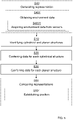
- According to some aspects, the above procedure can be reduced to three steps:
- Collect sensor data, for example from a point cloud.
- Project sensor data, such as the point cloud, to the horizontal plane x-y.
- Find lines and circles.
- In an optional fourth step, sequentially observed lines and circles can be merged to better estimate the position. The representation is then according to some aspects refined by merging measurement results over time.
- The resulting data structure is according to some aspects a geometric representation of either circles or lines.
- The present disclosure is not limited to mapping of landmarks in localization applications as indicated above, where an example of determining a type of area in which the
ego vehicle 1 is travelling. - According to some aspects, the type of environment is determined, or classified. For example, if cylindrical structures dominate, then it is classified as a forest type area, if planar structures dominate it is classified as a rural or urban type area, and if there are very few landmarks present it is classified as an open field type are, or the like.
- Determining the type of environment surrounding the
ego vehicle 1 is desired in order to estimate what kind of risks that are likely to occur, for example for automated safety systems and driver assist systems. For example, pedestrians are more likely to approach theego vehicle 1 in urban areas than in forested areas. Furthermore, wild animals can suddenly approach theego vehicle 1 in a forest type environment. - Generally, probabilities for one or more events can then be determined in dependence of the identified environment type.
- Furthermore, with reference to
Figure 3 , apart from the previously describedmain control unit 4 and theenvironment detection arrangement 5, thevehicle control system 3 comprises adriver assist unit 14 that is adapted to control theego vehicle 1 in dependence of the determined position and/or the determined environment type. According to some aspects, thevehicle control system 3 also comprises amap unit 15 that comprises is adapted to store and/or download map representations, for example via GNSS (Global Navigation Satellite System). -
Figure 4 schematically illustrates amain control unit 4 according to aspects of the present disclosure. It is appreciated that the above described methods and techniques may be realized in hardware. This hardware is then arranged to perform the methods, whereby the same advantages and effects are obtained as have been discussed above. -
Processing circuitry 410 is provided using any combination of one or more of a suitable central processing unit (CPU), multiprocessor, microcontroller, digital signal processor (DSP), etc., capable of executing software instructions stored in a computer program product, e.g. in the form of astorage medium 430. Theprocessing circuitry 410 may further be provided as at least one application specific integrated circuit (ASIC), or field programmable gate array (FPGA). - Particularly, the
processing circuitry 410 is configured to cause themain control unit 4 to perform a set of operations, or steps. For example, thestorage medium 430 may store the set of operations, and theprocessing circuitry 410 may be configured to retrieve the set of operations from thestorage medium 430 to cause the classification unit to perform the set of operations. The set of operations may be provided as a set of executable instructions. Thus, theprocessing circuitry 410 is thereby arranged to execute methods as herein disclosed. - The
storage medium 430 may also comprise persistent storage, which, for example, can be any single one or combination of magnetic memory, optical memory, solid state memory or even remotely mounted memory. - The
main control unit 4 may further comprise acommunications interface 420 for communications with at least one external device such as thedetection arrangement 5, the driver assistunit 14 and themap unit 15. As such, thecommunication interface 420 may comprise one or more transmitters and receivers, comprising analogue and digital components and a suitable number ports for wireline or wireless communication. - The
processing circuitry 410 controls the general operation of the unit, e.g. by sending data and control signals to thecommunication interface 420 and thestorage medium 430, by receiving data and reports from thecommunication interface 420, and by retrieving data and instructions from thestorage medium 430. Other components, as well as the related functionality, of the unit are omitted in order not to obscure the concepts presented herein. - With reference to
Figure 5 , the present disclosure generally relates to a method for representing an environment. The method comprises identifying S10 cylindrical structures and planar structures that mainly extend along a vertical extension in a coordinatesystem 13, and conferring S20 each identified cylindrical structure a first identification and a corresponding coordinate in a 2-dimensional projection x-y of the coordinatesystem 13. The method further comprises conferring S30 each identified planar structure a second identification and a corresponding coordinate in the 2-dimensional projection x-y of the coordinatesystem 13. - The method comprises generating S40 a representation of an environment by first obtaining S401 3-dimensional environment data in a coordinate system.
- Obtaining S401 3-dimensional environment data comprises acquiring S4001 environment data from an environment
detection sensor arrangement 5. - The method furhter comprises comparing S50 a first representation with a second representation, where the first representation is based on environment data acquired from the environment
detection sensor arrangement 5. The second representation is based on predefined reference data. - The comparison S50 is used for establishing S501 a position of a vehicle that is using the environment
detection sensor arrangement 5. - According to some aspects, the predefined reference data comprises map data.
- The method comprises identifying an environment type based on the representation and determining probabilities for one or more events in dependence of the identified environment type.
- According to some aspects, the representation is refined by merging measurement results over time.
- According to some aspects, the method is used for controlling an
ego vehicle 1. - The present disclosure thus generally relates to a representation of the environment, using cylindrical structures and planar structures that mainly extend along a vertical extension in a coordinate system. By conferring each identified cylindrical structure a first identification and a corresponding coordinate and conferring each identified planar structure a second identification and a corresponding coordinate, a very efficient representation of the environment is obtained in terms of storage requirements.
- This representation can be used in many ways, and a few examples have been presented, where one example relates to determining a position and one other example relates to determining a present environment type. There can be many other uses for an efficient representation according to the present disclosure. Line of sight is important to know for free space detection but also where different objects could be expected to appear. This representation can for example be used as a prior in risk assessment when assessing safe operation and threats from occluded objects that can potentially appear.
- The present disclosure is not limited to the examples above, but may vary freely within the scope of the appended claims. For example, there is at least one environment detection sensor, where the environment detection sensors 3a, 3b can be based on any suitable technology such as camera, radar, Lidar, V2X communication, ultrasonic etc.
- The 2-dimensional projection x-y of the coordinate
system 13 can be in any plane; according to some aspects and as described in the examples above in a horizontal plane. - According to some aspects, the stored map representation is updated by means of the processed representation of the environment. For example if a fence has been erected, and a tree has been removed, the corresponding information in the processed representation of the environment is used for updating the stored map representation.
- Generally, the present disclosure also relates to a
vehicle control system 3 adapted for anego vehicle 1 travelling on aroad 2. Thevehicle control system 3 comprises amain control unit 4 and an environmentdetection sensor arrangement 5 that is adapted to provide an initial detected representation of the environment. Themain control unit 4 is arranged to provide a processed representation of the environment by being adapted to - identify cylindrical structures and planar structures that mainly extend along a vertical extension z in a 3-dimensional coordinate
system 13 from the detected representation of the environment, to - confer a first identification that corresponds to a cylindrical structure, and a corresponding coordinate in a 2-dimensional projection x-y of the coordinate
system 13, for each identified cylindrical structure, and to - confer a second identification that corresponds to a planar structure, and a corresponding coordinate in the 2-dimensional projection x-y of the coordinate
system 13 for each identified planar structure. - The
main control unit 4 is arranged to compare a first representation with a second representation, where the first representation is based on the processed representation of the environment, and where the second representation is based on predefined reference data. - The
main control unit 4 is arranged to establish a position of theego vehicle 1 based on the comparison. - The
main control unit 4 is arranged to identify an environment type based on the processed representation of the environment, and to determine probabilities for one or more events in dependence of the identified environment type. - The
vehicle control system 3 comprises adriver assist unit 14 that is adapted to control theego vehicle 1.
Claims (4)
- A method performed by a vehicle control system, for representing an environment, wherein the vehicle control system comprises a main control unit (4), an environment detection sensor arrangement (5) and a driver assist unit (14), and wherein the method comprises generating (S40) a representation of an environment by:first obtaining (S401) 3-dimensional environment data in a coordinate system, wherein the obtaining (S401) of 3-dimensional environment data comprises acquiring (S4001) environment data from the environment detection sensor arrangement (5);identifying (S10) cylindrical structures and planar structures that mainly extend along a vertical extension in a coordinate system (13);conferring (S20) each identified cylindrical structure a first identification and a corresponding coordinate in a 2-dimensional projection (x-y) of the coordinate system (13); andconferring (S30) each identified planar structure a second identification and a corresponding coordinate in the 2-dimensional projection (x-y) of the coordinate system (13);
the method further comprisingcomparing (S50) a first representation with a second representation, where the first representation is based on environment data acquired from the environment detection sensor arrangement (5), and where the second representation is based on predefined reference data, wherein the comparison (S50) is used for establishing (S501) a position of a vehicle that is using the environment detection sensor arrangement (5); and characterized in that the method further comprises:identifying an environment type based on the representation, and determining probabilities for one or more events in dependence of the identified environment type;using the representation as a prior in risk assessment when assessing safe operation and threats from occluded objects that can potentially appear; andadapting the driver assist unit (14), through the vehicle control system, and in dependence of the determined position and/or the determined environment type, to control an ego vehicle. - The method according to claim 1, wherein the predefined reference data comprises map data.
- The method according to any one of the claims 1 j or 2,
wherein the representation is refined by merging measurement results over time. - A vehicle control system (3) adapted for an ego vehicle (1) travelling on a road (2), the vehicle control system (3) comprising a driver assist unit (14) that is adapted to control the ego vehicle (1), a main control unit (4) and an environment detection sensor arrangement (5) that is adapted to provide an initial detected representation of the environment, where the main control unit (4) is arranged to provide a processed representation of the environment by being adapted to- obtain 3-dimensional environment data in a coordinate system by being adapted to acquire environment data from the environment detection sensor arrangement (5),- identify cylindrical structures and planar structures that mainly extend along a vertical extension (z) in a 3-dimensional coordinate system (13) from the detected representation of the environment, to- confer a first identification that corresponds to a cylindrical structure, and a corresponding coordinate in a 2-dimensional projection (x-y) of the coordinate system (13) for each identified cylindrical structure, and to- confer a second identification that corresponds to a planar structure, and a corresponding coordinate in the 2-dimensional projection x-y of the coordinate system 13 for each identified planar structure,- compare a first representation with a second representation, where the first representation is based on environment data acquired from the environment detection sensor arrangement (5), and where the second representation is based on predefined reference data,- establish a position of the ego vehicle (1) based on the comparison,and characterized in that the main control unit (4) is further arranged to:- identify an environment type based on the processed representation of the environment, and to determine probabilities for one or more events in dependence of the identified environment type,- use the representation as a prior in risk assessment when assessing safe operation and threats from occluded objects that can potentially appear, and- adapt the driver assist unit (14), through the vehicle control system, and in dependence of the determined position and/or the determined environment type, to control an ego vehicle.
Priority Applications (1)
| Application Number | Priority Date | Filing Date | Title |
|---|---|---|---|
| EP19156681.9A EP3696507B1 (en) | 2019-02-12 | 2019-02-12 | Representing an environment by cylindrical and planar structures |
Applications Claiming Priority (1)
| Application Number | Priority Date | Filing Date | Title |
|---|---|---|---|
| EP19156681.9A EP3696507B1 (en) | 2019-02-12 | 2019-02-12 | Representing an environment by cylindrical and planar structures |
Publications (2)
| Publication Number | Publication Date |
|---|---|
| EP3696507A1 EP3696507A1 (en) | 2020-08-19 |
| EP3696507B1 true EP3696507B1 (en) | 2022-04-20 |
Family
ID=65433470
Family Applications (1)
| Application Number | Title | Priority Date | Filing Date |
|---|---|---|---|
| EP19156681.9A Active EP3696507B1 (en) | 2019-02-12 | 2019-02-12 | Representing an environment by cylindrical and planar structures |
Country Status (1)
| Country | Link |
|---|---|
| EP (1) | EP3696507B1 (en) |
Family Cites Families (3)
| Publication number | Priority date | Publication date | Assignee | Title |
|---|---|---|---|---|
| US9235214B2 (en) * | 2008-09-11 | 2016-01-12 | Deere & Company | Distributed knowledge base method for vehicular localization and work-site management |
| US9298992B2 (en) * | 2014-02-20 | 2016-03-29 | Toyota Motor Engineering & Manufacturing North America, Inc. | Geographic feature-based localization with feature weighting |
| EP3845427A1 (en) | 2015-02-10 | 2021-07-07 | Mobileye Vision Technologies Ltd. | Sparse map for autonomous vehicle navigation |
-
2019
- 2019-02-12 EP EP19156681.9A patent/EP3696507B1/en active Active
Also Published As
| Publication number | Publication date |
|---|---|
| EP3696507A1 (en) | 2020-08-19 |
Similar Documents
| Publication | Publication Date | Title |
|---|---|---|
| CN109214248B (en) | Method and device for identifying laser point cloud data of unmanned vehicle | |
| KR102273559B1 (en) | Method, apparatus, and computer readable storage medium for updating electronic map | |
| CN109405836B (en) | Method and system for determining drivable navigation paths of unmanned vehicles | |
| CN108319655B (en) | Method and device for generating grid map | |
| CN110687549B (en) | Obstacle detection method and device | |
| CN108303103B (en) | Method and device for determining target lane | |
| CN108369420B (en) | Apparatus and method for autonomous positioning | |
| CN111220993B (en) | Target scene positioning method and device, computer equipment and storage medium | |
| JP6166294B2 (en) | Automatic driving system, automatic driving method and computing device | |
| JP7082545B2 (en) | Information processing methods, information processing equipment and programs | |
| Brenner | Extraction of features from mobile laser scanning data for future driver assistance systems | |
| WO2019007263A1 (en) | Method and device for calibrating external parameters of vehicle-mounted sensor | |
| US9576200B2 (en) | Background map format for autonomous driving | |
| CN111108342A (en) | Visual ranging and pairwise alignment for high definition map creation | |
| EP3032221A1 (en) | Method and system for improving accuracy of digital map data utilized by a vehicle | |
| US20220244067A1 (en) | Submap geographic projections | |
| CN109917791B (en) | Method for automatically exploring and constructing map by mobile device | |
| EP3671278B1 (en) | Road surface detection | |
| US11668573B2 (en) | Map selection for vehicle pose system | |
| US20220113139A1 (en) | Object recognition device, object recognition method and program | |
| WO2022178738A1 (en) | Method and system for generating a topological graph map | |
| KR102255924B1 (en) | Vehicle and method for detecting lane | |
| EP3696507B1 (en) | Representing an environment by cylindrical and planar structures | |
| KR102130687B1 (en) | System for information fusion among multiple sensor platforms | |
| US20230236021A1 (en) | Information processing device |
Legal Events
| Date | Code | Title | Description |
|---|---|---|---|
| PUAI | Public reference made under article 153(3) epc to a published international application that has entered the european phase |
Free format text: ORIGINAL CODE: 0009012 |
|
| STAA | Information on the status of an ep patent application or granted ep patent |
Free format text: STATUS: THE APPLICATION HAS BEEN PUBLISHED |
|
| AK | Designated contracting states |
Kind code of ref document: A1 Designated state(s): AL AT BE BG CH CY CZ DE DK EE ES FI FR GB GR HR HU IE IS IT LI LT LU LV MC MK MT NL NO PL PT RO RS SE SI SK SM TR |
|
| AX | Request for extension of the european patent |
Extension state: BA ME |
|
| STAA | Information on the status of an ep patent application or granted ep patent |
Free format text: STATUS: REQUEST FOR EXAMINATION WAS MADE |
|
| 17P | Request for examination filed |
Effective date: 20210217 |
|
| RBV | Designated contracting states (corrected) |
Designated state(s): AL AT BE BG CH CY CZ DE DK EE ES FI FR GB GR HR HU IE IS IT LI LT LU LV MC MK MT NL NO PL PT RO RS SE SI SK SM TR |
|
| STAA | Information on the status of an ep patent application or granted ep patent |
Free format text: STATUS: EXAMINATION IS IN PROGRESS |
|
| 17Q | First examination report despatched |
Effective date: 20210608 |
|
| GRAP | Despatch of communication of intention to grant a patent |
Free format text: ORIGINAL CODE: EPIDOSNIGR1 |
|
| STAA | Information on the status of an ep patent application or granted ep patent |
Free format text: STATUS: GRANT OF PATENT IS INTENDED |
|
| INTG | Intention to grant announced |
Effective date: 20211130 |
|
| GRAS | Grant fee paid |
Free format text: ORIGINAL CODE: EPIDOSNIGR3 |
|
| GRAA | (expected) grant |
Free format text: ORIGINAL CODE: 0009210 |
|
| STAA | Information on the status of an ep patent application or granted ep patent |
Free format text: STATUS: THE PATENT HAS BEEN GRANTED |
|
| AK | Designated contracting states |
Kind code of ref document: B1 Designated state(s): AL AT BE BG CH CY CZ DE DK EE ES FI FR GB GR HR HU IE IS IT LI LT LU LV MC MK MT NL NO PL PT RO RS SE SI SK SM TR |
|
| REG | Reference to a national code |
Ref country code: GB Ref legal event code: FG4D |
|
| REG | Reference to a national code |
Ref country code: CH Ref legal event code: EP |
|
| REG | Reference to a national code |
Ref country code: IE Ref legal event code: FG4D |
|
| REG | Reference to a national code |
Ref country code: DE Ref legal event code: R096 Ref document number: 602019013797 Country of ref document: DE |
|
| REG | Reference to a national code |
Ref country code: AT Ref legal event code: REF Ref document number: 1485466 Country of ref document: AT Kind code of ref document: T Effective date: 20220515 |
|
| REG | Reference to a national code |
Ref country code: LT Ref legal event code: MG9D |
|
| REG | Reference to a national code |
Ref country code: NL Ref legal event code: MP Effective date: 20220420 |
|
| REG | Reference to a national code |
Ref country code: AT Ref legal event code: MK05 Ref document number: 1485466 Country of ref document: AT Kind code of ref document: T Effective date: 20220420 |
|
| PG25 | Lapsed in a contracting state [announced via postgrant information from national office to epo] |
Ref country code: NL Free format text: LAPSE BECAUSE OF FAILURE TO SUBMIT A TRANSLATION OF THE DESCRIPTION OR TO PAY THE FEE WITHIN THE PRESCRIBED TIME-LIMIT Effective date: 20220420 |
|
| PG25 | Lapsed in a contracting state [announced via postgrant information from national office to epo] |
Ref country code: SE Free format text: LAPSE BECAUSE OF FAILURE TO SUBMIT A TRANSLATION OF THE DESCRIPTION OR TO PAY THE FEE WITHIN THE PRESCRIBED TIME-LIMIT Effective date: 20220420 Ref country code: PT Free format text: LAPSE BECAUSE OF FAILURE TO SUBMIT A TRANSLATION OF THE DESCRIPTION OR TO PAY THE FEE WITHIN THE PRESCRIBED TIME-LIMIT Effective date: 20220822 Ref country code: NO Free format text: LAPSE BECAUSE OF FAILURE TO SUBMIT A TRANSLATION OF THE DESCRIPTION OR TO PAY THE FEE WITHIN THE PRESCRIBED TIME-LIMIT Effective date: 20220720 Ref country code: LT Free format text: LAPSE BECAUSE OF FAILURE TO SUBMIT A TRANSLATION OF THE DESCRIPTION OR TO PAY THE FEE WITHIN THE PRESCRIBED TIME-LIMIT Effective date: 20220420 Ref country code: HR Free format text: LAPSE BECAUSE OF FAILURE TO SUBMIT A TRANSLATION OF THE DESCRIPTION OR TO PAY THE FEE WITHIN THE PRESCRIBED TIME-LIMIT Effective date: 20220420 Ref country code: GR Free format text: LAPSE BECAUSE OF FAILURE TO SUBMIT A TRANSLATION OF THE DESCRIPTION OR TO PAY THE FEE WITHIN THE PRESCRIBED TIME-LIMIT Effective date: 20220721 Ref country code: FI Free format text: LAPSE BECAUSE OF FAILURE TO SUBMIT A TRANSLATION OF THE DESCRIPTION OR TO PAY THE FEE WITHIN THE PRESCRIBED TIME-LIMIT Effective date: 20220420 Ref country code: ES Free format text: LAPSE BECAUSE OF FAILURE TO SUBMIT A TRANSLATION OF THE DESCRIPTION OR TO PAY THE FEE WITHIN THE PRESCRIBED TIME-LIMIT Effective date: 20220420 Ref country code: BG Free format text: LAPSE BECAUSE OF FAILURE TO SUBMIT A TRANSLATION OF THE DESCRIPTION OR TO PAY THE FEE WITHIN THE PRESCRIBED TIME-LIMIT Effective date: 20220720 Ref country code: AT Free format text: LAPSE BECAUSE OF FAILURE TO SUBMIT A TRANSLATION OF THE DESCRIPTION OR TO PAY THE FEE WITHIN THE PRESCRIBED TIME-LIMIT Effective date: 20220420 |
|
| PG25 | Lapsed in a contracting state [announced via postgrant information from national office to epo] |
Ref country code: RS Free format text: LAPSE BECAUSE OF FAILURE TO SUBMIT A TRANSLATION OF THE DESCRIPTION OR TO PAY THE FEE WITHIN THE PRESCRIBED TIME-LIMIT Effective date: 20220420 Ref country code: PL Free format text: LAPSE BECAUSE OF FAILURE TO SUBMIT A TRANSLATION OF THE DESCRIPTION OR TO PAY THE FEE WITHIN THE PRESCRIBED TIME-LIMIT Effective date: 20220420 Ref country code: LV Free format text: LAPSE BECAUSE OF FAILURE TO SUBMIT A TRANSLATION OF THE DESCRIPTION OR TO PAY THE FEE WITHIN THE PRESCRIBED TIME-LIMIT Effective date: 20220420 Ref country code: IS Free format text: LAPSE BECAUSE OF FAILURE TO SUBMIT A TRANSLATION OF THE DESCRIPTION OR TO PAY THE FEE WITHIN THE PRESCRIBED TIME-LIMIT Effective date: 20220820 |
|
| REG | Reference to a national code |
Ref country code: DE Ref legal event code: R097 Ref document number: 602019013797 Country of ref document: DE |
|
| PG25 | Lapsed in a contracting state [announced via postgrant information from national office to epo] |
Ref country code: SM Free format text: LAPSE BECAUSE OF FAILURE TO SUBMIT A TRANSLATION OF THE DESCRIPTION OR TO PAY THE FEE WITHIN THE PRESCRIBED TIME-LIMIT Effective date: 20220420 Ref country code: SK Free format text: LAPSE BECAUSE OF FAILURE TO SUBMIT A TRANSLATION OF THE DESCRIPTION OR TO PAY THE FEE WITHIN THE PRESCRIBED TIME-LIMIT Effective date: 20220420 Ref country code: RO Free format text: LAPSE BECAUSE OF FAILURE TO SUBMIT A TRANSLATION OF THE DESCRIPTION OR TO PAY THE FEE WITHIN THE PRESCRIBED TIME-LIMIT Effective date: 20220420 Ref country code: EE Free format text: LAPSE BECAUSE OF FAILURE TO SUBMIT A TRANSLATION OF THE DESCRIPTION OR TO PAY THE FEE WITHIN THE PRESCRIBED TIME-LIMIT Effective date: 20220420 Ref country code: DK Free format text: LAPSE BECAUSE OF FAILURE TO SUBMIT A TRANSLATION OF THE DESCRIPTION OR TO PAY THE FEE WITHIN THE PRESCRIBED TIME-LIMIT Effective date: 20220420 Ref country code: CZ Free format text: LAPSE BECAUSE OF FAILURE TO SUBMIT A TRANSLATION OF THE DESCRIPTION OR TO PAY THE FEE WITHIN THE PRESCRIBED TIME-LIMIT Effective date: 20220420 |
|
| PLBE | No opposition filed within time limit |
Free format text: ORIGINAL CODE: 0009261 |
|
| STAA | Information on the status of an ep patent application or granted ep patent |
Free format text: STATUS: NO OPPOSITION FILED WITHIN TIME LIMIT |
|
| 26N | No opposition filed |
Effective date: 20230123 |
|
| PG25 | Lapsed in a contracting state [announced via postgrant information from national office to epo] |
Ref country code: AL Free format text: LAPSE BECAUSE OF FAILURE TO SUBMIT A TRANSLATION OF THE DESCRIPTION OR TO PAY THE FEE WITHIN THE PRESCRIBED TIME-LIMIT Effective date: 20220420 |
|
| PGFP | Annual fee paid to national office [announced via postgrant information from national office to epo] |
Ref country code: FR Payment date: 20230109 Year of fee payment: 5 |
|
| PG25 | Lapsed in a contracting state [announced via postgrant information from national office to epo] |
Ref country code: SI Free format text: LAPSE BECAUSE OF FAILURE TO SUBMIT A TRANSLATION OF THE DESCRIPTION OR TO PAY THE FEE WITHIN THE PRESCRIBED TIME-LIMIT Effective date: 20220420 |
|
| PG25 | Lapsed in a contracting state [announced via postgrant information from national office to epo] |
Ref country code: MC Free format text: LAPSE BECAUSE OF FAILURE TO SUBMIT A TRANSLATION OF THE DESCRIPTION OR TO PAY THE FEE WITHIN THE PRESCRIBED TIME-LIMIT Effective date: 20220420 |
|
| REG | Reference to a national code |
Ref country code: CH Ref legal event code: PL |
|
| REG | Reference to a national code |
Ref country code: BE Ref legal event code: MM Effective date: 20230228 |
|
| GBPC | Gb: european patent ceased through non-payment of renewal fee |
Effective date: 20230212 |
|
| PG25 | Lapsed in a contracting state [announced via postgrant information from national office to epo] |
Ref country code: LU Free format text: LAPSE BECAUSE OF NON-PAYMENT OF DUE FEES Effective date: 20230212 Ref country code: LI Free format text: LAPSE BECAUSE OF NON-PAYMENT OF DUE FEES Effective date: 20230228 Ref country code: CH Free format text: LAPSE BECAUSE OF NON-PAYMENT OF DUE FEES Effective date: 20230228 |
|
| REG | Reference to a national code |
Ref country code: IE Ref legal event code: MM4A |
|
| PG25 | Lapsed in a contracting state [announced via postgrant information from national office to epo] |
Ref country code: GB Free format text: LAPSE BECAUSE OF NON-PAYMENT OF DUE FEES Effective date: 20230212 |
|
| PG25 | Lapsed in a contracting state [announced via postgrant information from national office to epo] |
Ref country code: IT Free format text: LAPSE BECAUSE OF FAILURE TO SUBMIT A TRANSLATION OF THE DESCRIPTION OR TO PAY THE FEE WITHIN THE PRESCRIBED TIME-LIMIT Effective date: 20220420 Ref country code: IE Free format text: LAPSE BECAUSE OF NON-PAYMENT OF DUE FEES Effective date: 20230212 Ref country code: GB Free format text: LAPSE BECAUSE OF NON-PAYMENT OF DUE FEES Effective date: 20230212 |
|
| PG25 | Lapsed in a contracting state [announced via postgrant information from national office to epo] |
Ref country code: BE Free format text: LAPSE BECAUSE OF NON-PAYMENT OF DUE FEES Effective date: 20230228 |
|
| PGFP | Annual fee paid to national office [announced via postgrant information from national office to epo] |
Ref country code: DE Payment date: 20240109 Year of fee payment: 6 |