EP3696116A1 - High-bay storage and method for operating same - Google Patents
High-bay storage and method for operating same Download PDFInfo
- Publication number
- EP3696116A1 EP3696116A1 EP20155106.6A EP20155106A EP3696116A1 EP 3696116 A1 EP3696116 A1 EP 3696116A1 EP 20155106 A EP20155106 A EP 20155106A EP 3696116 A1 EP3696116 A1 EP 3696116A1
- Authority
- EP
- European Patent Office
- Prior art keywords
- maintenance
- fall protection
- protection device
- bay warehouse
- path
- Prior art date
- Legal status (The legal status is an assumption and is not a legal conclusion. Google has not performed a legal analysis and makes no representation as to the accuracy of the status listed.)
- Withdrawn
Links
Images

Classifications
-
- B—PERFORMING OPERATIONS; TRANSPORTING
- B65—CONVEYING; PACKING; STORING; HANDLING THIN OR FILAMENTARY MATERIAL
- B65G—TRANSPORT OR STORAGE DEVICES, e.g. CONVEYORS FOR LOADING OR TIPPING, SHOP CONVEYOR SYSTEMS OR PNEUMATIC TUBE CONVEYORS
- B65G1/00—Storing articles, individually or in orderly arrangement, in warehouses or magazines
- B65G1/02—Storage devices
- B65G1/04—Storage devices mechanical
- B65G1/0492—Storage devices mechanical with cars adapted to travel in storage aisles
-
- B—PERFORMING OPERATIONS; TRANSPORTING
- B65—CONVEYING; PACKING; STORING; HANDLING THIN OR FILAMENTARY MATERIAL
- B65G—TRANSPORT OR STORAGE DEVICES, e.g. CONVEYORS FOR LOADING OR TIPPING, SHOP CONVEYOR SYSTEMS OR PNEUMATIC TUBE CONVEYORS
- B65G43/00—Control devices, e.g. for safety, warning or fault-correcting
-
- B—PERFORMING OPERATIONS; TRANSPORTING
- B65—CONVEYING; PACKING; STORING; HANDLING THIN OR FILAMENTARY MATERIAL
- B65G—TRANSPORT OR STORAGE DEVICES, e.g. CONVEYORS FOR LOADING OR TIPPING, SHOP CONVEYOR SYSTEMS OR PNEUMATIC TUBE CONVEYORS
- B65G2207/00—Indexing codes relating to constructional details, configuration and additional features of a handling device, e.g. Conveyors
- B65G2207/40—Safety features of loads, equipment or persons
Definitions
- the present invention relates to a high-bay warehouse for storing piece goods, the high-bay warehouse comprising several storage levels arranged one above the other, each with a large number of storage spaces for the piece goods, the high-bay warehouse having several maintenance aisles arranged one above the other for maintenance personnel, via which the storage levels are accessible Maintenance aisles have guides along which rack vehicles can be moved, with the aid of which the piece goods can be delivered to the individual storage locations, the high-bay warehouse comprising at least one lifter connecting several storage levels in the vertical direction, with the aid of which the storage vehicles and / or the piece goods can be moved between individual storage levels, and wherein the lifter can be moved along a lifting path which connects the individual maintenance aisles with one another in the vertical direction.
- the invention relates to a method for operating a high-bay warehouse with at least one maintenance aisle and at least one lifter, the lifter being movable along a lifting path in the vertical direction, with a path between the maintenance aisle and the lifting path for maintenance personnel by means of a fall protection in one during normal operation Normal position is locked.
- High-bay warehouses and, in particular, automated high-bay warehouses are known and are used, for example, for the dynamic storage of piece goods and in particular when a high warehouse turnover rate is desired.
- a high-bay warehouse usually has a large number of horizontally running storage levels, each with a large number of storage spaces.
- the piece goods to be stored or retrieved are transported from and to the corresponding storage locations in particular by autonomous storage and retrieval vehicles.
- the shelf vehicles also "shuttles” or “shelf shuttles” called, move on the storage levels along guides, which usually only allow linear movement.
- the guides are arranged one above the other in an alley connecting the storage levels.
- high-bay storage facilities In order to transport the rack vehicles and / or the piece goods from one storage level to another storage level, high-bay storage facilities have lifters that move in the vertical direction along a lifting path perpendicular to the storage levels. Sometimes the lifting path is located within a shaft provided for the lifter.
- the object of the present invention is therefore to improve the safety for maintenance personnel in a high-bay warehouse.
- the high-bay warehouse according to the invention is suitable for storing piece goods and comprises several storage levels arranged one above the other, each with a large number of storage spaces for the piece goods.
- the high-bay warehouse also has several maintenance aisles, arranged one above the other, for maintenance personnel, via which the storage levels are accessible.
- the maintenance aisles in turn have guides (e.g. rails) along which rack vehicles, which preferably have rollers, can be moved, with the help of which the piece goods can be delivered to the individual storage locations.
- the high-bay warehouse includes at least one lifter connecting several storage levels in the vertical direction, with the aid of which the rack vehicles and / or the piece goods can be moved between individual storage levels, the lifter being movable along a lifting path that connects the individual maintenance aisles with one another in the vertical direction.
- At least one fall protection is assigned to each maintenance aisle, which can be moved between a normal position and an escape position, the fall protection in the normal position blocking the path between the corresponding maintenance aisle and the lifting path for the maintenance personnel. It is also provided that the fall protection in the aligned position clears the path between the mentioned maintenance aisle and the lifting path for the maintenance personnel and extends beyond that into the lifting path and thereby forms a fall protection for the maintenance personnel.
- the high-bay warehouse can, for example, also be operated with uniform storage containers in which the piece goods are transported and / or stored.
- the alignment of the fall protection is used in particular to escape the maintenance personnel, that is, to evacuate the high-bay warehouse as quickly as possible, for example in an emergency.
- the emergency can be an external incident such as a fire, earthquake, storm, power failure or flood.
- a medical emergency for maintenance personnel is conceivable, for example.
- the fall protection in the escape position can also be used to access the maintenance aisle. In this way, in an emergency, access can be created for the rescue service and fire brigade, for example.
- a high-bay warehouse can also have several copies of a feature (for example maintenance aisle, lifter, fall protection, etc.), with the properties and relationships described apply to each copy or, in the case of dual relationships, to each pair of copies.
- a feature for example maintenance aisle, lifter, fall protection, etc.
- the maintenance personnel in the area of the lifting path are protected against falling by the fall protection in the normal position. Due to the possibility of bringing the fall protection into the escape position, a short escape route is available in an emergency, with the extension of the fall protection into the lifting path also providing protection against a fall in the escape position.
- a change of position between the normal position and the escape position of the fall protection can be triggered by the maintenance staff.
- the escape position is automatically adopted in an emergency.
- a corresponding trigger mechanism for the fall protection is connected, for example, to a fire alarm system or a central emergency shutdown of the high-bay warehouse.
- the trigger mechanism is also preferably coupled to an emergency power supply system.
- the lifter can also be arranged in a lifting shaft, in which the lifting path would consequently also be located.
- the fall protection blocks the lifting shaft partially or completely in this case.
- the lifter can be brought into a basic position, for example directly above ground level, by the fall protection device in an emergency and in particular before the fall protection device is in alignment.
- the assumption of the basic position can be caused, for example, by the triggering of an alarm or the trigger mechanism of the fall protection.
- a control of the lifter is connected in particular to the trigger mechanism of the fall protection, the fire alarm system or the central emergency shutdown of the high-bay warehouse.
- the jack In the event of a power failure, the jack can be moved to its home position by gravity or by means of an emergency power supply system.
- the fall protection can be made in one piece or in several parts, with a multi-part construction, for example, one component blocking or clearing the path between the maintenance aisle and the lifting path and another component extending into the lifting path in the aligned position of the fall protection.
- the normal position and the aligned position are related in particular on different positions of all moving parts of the fall protection.
- a sign indicating a potential escape route can be arranged, the sign being in particular illuminated.
- Instructions for the maintenance staff, which describe how the fall protection can be brought into the escape position, can be attached in the area of the fall protection.
- the fall protection device has a folding mechanism.
- the folding mechanism represents a simple and robust way of ensuring that the fall protection device can move from the normal position to the aligned position.
- the fall protection device can be designed as a door, for example, the folding mechanism in this case being designed as a hinge, for example.
- a degree of freedom of movement of the folding mechanism can exist in the horizontal and / or vertical direction.
- the fall protection device or a part thereof can be brought from an upright to a lying position in a mechanically simple manner by the folding mechanism, the upright position preferably being the normal position and the lying position being the alignment position. In the lying position, the fall protection can serve as a step on the lifting path.
- the fall protection device has a locking device.
- the locking device ensures, on the one hand, the protective effect of the fall protection in the normal position by preventing an unwanted change of position. On the other hand, the locking device prevents misuse of the escape position of the fall protection by unintentional access to the maintenance aisle is prevented.
- the locking device can preferably be released by maintenance personnel. It is conceivable that the locking device can only be released in an emergency and / or only from the maintenance passage.
- the locking device can be designed as a simple mechanical bolt, but it is also conceivable that an electrically operated locking device, for example with an electromagnet, is provided.
- the fall protection device has cross struts, a vertical distance between the cross struts corresponding to at least one height of the rack vehicles.
- the cross struts serve to block the path between the maintenance aisle and the lifting path.
- the cross struts can serve as fall protection in the lifting path and possibly as a step surface for maintenance personnel.
- the distance between the cross struts is preferably chosen so that rack vehicles can pass the fall protection in the normal position. In this way, the operation of the high-bay warehouse is not impaired by the fall protection.
- the rack vehicles which are transported by the lifter along the lifting path over different storage levels, can get into the maintenance aisle between the cross struts.
- the distance between the transverse struts preferably corresponds to a sum of the height of the rack vehicles and a height of a transported piece goods or the sum of the height of the rack vehicles and the height of the already described uniform storage container.
- the transverse struts are preferably enclosed by a frame, so that the struts can be part of a type of door or a gate, for example.
- an actuating mechanism is arranged in the maintenance aisle, in particular in the area of the lifting path, which is designed to actuate the locking device and / or to initiate a movement of the fall protection from the normal position into the aligned position.
- the fall protection device can be quickly brought into the escape position in an emergency and the maintenance personnel can be evacuated in a short time.
- the actuation mechanism can for example be designed as a lever, crank or switch and can be a component of the locking device described above.
- the actuation mechanism can be triggered mechanically and / or electromagnetically and / or act on the fall protection device and / or the locking device. It is conceivable that the actuation mechanism is connected to an alarm and / or an intercom system. It is also conceivable that the actuating mechanism stops the lifter in its stroke path or moves it into a neutral position if the lifter blocks the alignment position.
- the actuation mechanism can in particular be color-coded and / or illuminated.
- the actuation mechanism can also be protected against inadvertent actuation by a protective flap.
- the fall protection device In the normal position, the fall protection device can be in a metastable state, this state being disturbed by the actuating mechanism in such a way that an independent assumption of the escape position is caused.
- the fall protection device can have a motor, for example an electric motor, which at least supports the movement of the fall protection device from the normal position into the aligned position.
- a counterweight can also be provided, which reduces a force required to move the fall protection device.
- the actuation mechanism can activate the electric motor and / or release the counterweight.
- a ladder is arranged on the lifting path.
- the ladder is used by the maintenance personnel to overcome a difference in height between the maintenance aisle and a floor level.
- the fall protection device can in particular bridge the path between the maintenance aisle and the ladder.
- the ladder can have a back or fall protection.
- the ladder can have an entrance at the level of each maintenance corridor.
- the ladder can be pushed in upwards outside of the emergency, the ladder preferably having a release mechanism that causes the ladder to extend.
- the release mechanism can, for example, be triggered manually by maintenance personnel or automatically in an emergency. It is also conceivable that the trigger mechanism is triggered when one of the fall protection devices is in the alignment position.
- a staircase, slide or rod can also be arranged on the lifting path.
- the fall protection device advantageously comprises an escape door and a movable step surface, the movable step surface extending into the lifting path in the aligned position.
- the escape door and the movable step surface can largely be designed independently of one another and thus with greater flexibility.
- the escape door In the normal position, the escape door preferably blocks the path between the maintenance aisle and the lifting path and accordingly releases this path in the escape position.
- the escape door and the movable step surface are in particular mechanically and / or electrically coupled.
- the movable step surface can be located in the normal position, for example, below the maintenance aisle and can preferably completely block the lifting path in the aligned position. For this purpose, it is advantageous if the step surface is mounted in such a way that, starting from a waiting position, it can be pivoted or shifted into the alignment position.
- the escape door preferably comprises the struts described above.
- the method according to the invention is used to operate a high-bay warehouse with at least one maintenance aisle and at least one Lifter, the lifter being movable in the vertical direction along a lifting path.
- a path between the maintenance aisle and the lifting path is blocked for maintenance personnel by a fall protection device, which is in a normal position.
- the fall protection device is brought from the normal position into an alignment position in an emergency.
- the path between the maintenance aisle and the lifting path is released for the maintenance personnel and the lifting path is at least partially blocked by the fall protection, so that a fall protection is formed for the maintenance personnel.
- the method enables a high-bay warehouse to be operated with a high degree of safety for maintenance personnel.
- the risk of the maintenance personnel falling into the lifting path is minimized by the fall protection in the normal position during normal operation.
- the fall protection is brought into the escape position, which opens up an additional, short escape route for the maintenance staff.
- the at least partial blocking of the lifting path by the fall protection creates fall protection for the maintenance personnel even in an emergency.
- the fall protection can for example be brought into the escape position by maintenance personnel.
- a sensor signal in particular from a fire alarm or smoke alarm, can be the trigger for automatically adopting the escape position.
- a manual triggering of a fire alarm or an emergency stop switch can also be used as a trigger.
- an alarm is triggered when the fall protection device is in the escape position.
- the alarm can alert other maintenance personnel to an emergency and either cause them to flee or call for help for maintenance personnel in need.
- the alarm automatically informs rescue workers and in particular the fire brigade.
- the alarm can also ensure that the escape position of the fall protection is only used for real emergencies and not, for example, for convenience or to create unauthorized access to the maintenance aisle.
- the fall protection device is also brought into the aligned position in the event of maintenance in order to provide the maintenance personnel with access to the maintenance passage.
- Maintenance of the high-bay warehouse can thus be carried out in a simplified or time-saving manner.
- This also provides an advantageous escape route in an emergency without any additional measures required. In this case, however, the corresponding jack must be shut down for the duration of the maintenance.
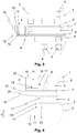
- Figure 1 shows first of all a high-bay warehouse 1 according to the prior art.
- the piece goods 4 can be located in uniform storage containers.
- Maintenance aisles 5 are located in the middle between the storage spaces 3, in which maintenance personnel 6 can move on intermediate floors 7 in the event of maintenance.
- the maintenance aisles 5 have guides 8 along which shelf vehicles 9 can be moved. Especially if one of the storage and retrieval vehicles 9 fails, the maintenance personnel 6 must stay in one of the maintenance aisles 5.
- the shelf storage vehicles 9 are preferably designed to independently transport the piece goods 4 and any storage containers that may be present in the high-bay warehouse 1 and to store and retrieve them at the storage locations 3.
- the rack vehicles 9, which may be loaded with piece goods 4 can move the storage levels 2 with the aid of a lifter 10 ( Figure 2 ) switch.
- the rack vehicles 9 each have a height h.
- FIG 2 a high-bay warehouse 1 according to the invention is shown.
- the detail shows in particular the surroundings of a lifting path 11 along which the lifter 10 can be moved.
- the lifting path 11 can be located in a shaft, for example.
- the maintenance aisles 5 adjoin the lifting path 11, whereby there is a risk of the maintenance personnel 6 falling into the lifting path 11 in the maintenance aisle 5.
- a fall protection device 12 is assigned to each maintenance aisle 5.
- the fall protection devices 12 can be moved between a normal position 13 and an alignment position 14.
- two maintenance aisles 5, each with a fall protection device 12 are shown as an example.
- the lower of the two fall protection devices 12 is in the normal position 13 and blocks the path between the maintenance aisle 5 and the lifting path 11 in this position. In this way, the maintenance personnel 6 is protected from falling into the lifting path 11 during normal operation.
- the fall protection device 12 is locked in the normal position 13 during normal operation, for example by a locking device 15.
- the fall protection device 12 in the escape position 14 creates a short escape route for the maintenance personnel 6 at risk.
- the upper of the two fall protection devices 12 is in the alignment position 14.
- the fall protection device 12 clears the path between the maintenance aisle 5 and the lifting path 11 for the maintenance personnel 6.
- the fall protection device 12 extends into the lift path 11 in the escape position 14 and thereby forms a fall protection for the maintenance staff 6.
- the maintenance staff 6 can also use the fall protection device 12 in the escape position 14, for example, to bridge the lift path 11.
- the fall protection device 12 completely blocks the lifting path 11 in the alignment position 14.
- the change in position of the fall protection device 12 from the normal position 13 to the aligned position 14 is made possible, for example, by a folding mechanism 16 which can in particular comprise a hinge.
- the assumption of the escape position 14 of the fall protection device 12 can be triggered, for example, by an actuating mechanism 17, the actuating mechanism 17 being designed, for example, as a switch.
- the actuation mechanism 17 can be triggered by the maintenance staff 6 in the maintenance aisle 5, which opens up the escape route via the lifting path 11.
- the operating mechanism 17 can in particular release the locking device 15. It is conceivable that the fall protection device 12 is held in the normal position 13 exclusively by the locking device 15 and the fall protection device 12 automatically assumes the alignment position 14 when the locking device 15 is released.
- the actuation mechanism 17 can, for example, be in operative connection with the fall protection device 12 and / or the locking device 15 via a circuit.
- Actuating mechanism 17 and locking device 15 can also be part of a single component, for example in the form of a bolt with a lever.
- the lifter 10 is preferably shut down if one of the fall protection devices 12 is in the aligned position 14. The shutdown can also take place when one of the actuating mechanisms 17 is triggered, for example.
- a ladder 18 for the further escape of the maintenance personnel 6 is preferably arranged on the lifting path 11. The ladder 18 can have a back or fall protection, the ladder 18 having an entrance in particular at the level of each maintenance aisle 5.
- the fall protection 12 in the escape position 14 can also enable access to the corresponding maintenance aisle 5, for example for first aiders, firefighters or maintenance staff 6, in particular also during normal operation.
- Figure 3 shows a top view of the high-bay warehouse 1 just described.
- the fall protection device 12 shown is in the aligned position 14.
- the fall protection device 12 has transverse struts 19, the transverse struts 19 in the normal position 13 preventing the maintenance personnel 6 from falling.
- the cross struts 19 are arranged at a distance a which preferably corresponds to at least the height h of the rack vehicles 9. This makes it possible for the shelf vehicles 9 to pass the fall protection device 12 in the normal position 13. The operation of the high-bay warehouse 1 is thus not impaired by the fall protection device 12 in the normal position 13. Nevertheless, the fall protection 12 in the escape position 14 forms a fall protection for the maintenance personnel 6 and can optionally be used to bridge the lifting path 11.
- Figure 4 shows a side view of a further embodiment of the high-bay warehouse 1 according to the invention.
- the fall protection 12 is designed in two parts, the fall protection 12 comprising an escape door 20 and a movable step surface 21.
- the escape door 20 In the normal position 13, the escape door 20 is closed and thus blocks the path between the maintenance aisle 5 and the lifting path 11.
- the escape door 20 can be moved with the aid of a folding mechanism 16, the folding mechanism 16 being designed as a door hinge in this example.
- the movable step surface 21 is in the normal position 13, for example, below the intermediate floor 7 and does not impair the operation of the high-bay warehouse 1 as a result.
- the movable step surface 21 extends into the stroke path 11.
- the movable step surface 21 completely blocks the stroke path 11 in the alignment position 14, whereby the maintenance personnel 6 can safely cross the stroke path 11 during the escape.
- the movable step surface 21 can be brought from the normal position 13 into the aligned position 14 with the aid of telescopic rails, for example.
- the escape door 20 has transverse struts 19, whereby, as before, these are preferably arranged at a distance a which corresponds at least to the height h of the rack vehicles 9.
- the escape door 20 and the movable step surface 21 can in particular be electrically and / or mechanically coupled, a change in position of the escape door 20 likewise causing a change in position of the movable step surface 21 and vice versa. It is conceivable that in the alignment position 14 both the movable step surface 21 and the escape door 20 extend into the lifting path 11.
Landscapes
- Engineering & Computer Science (AREA)
- Mechanical Engineering (AREA)
- Warehouses Or Storage Devices (AREA)
Abstract
Die Erfindung betrifft ein Hochregallager (1) zum Lagern von Stückgut (4) mit mehreren übereinander angeordneten Lagerebenen (2) und einer Vielzahl von Lagerplätzen (3) für das Stückgut (4). Das Hochregallager (1) weist mehrere übereinander angeordnete Wartungsgänge (5) für ein Wartungspersonal (6) auf, über die die Lagerebenen (2) zugänglich sind. Die Wartungsgänge (5) weisen Führungen (8) auf, entlang derer Regalfahrzeuge (9) bewegbar sind, mit deren Hilfe das Stückgut (4) den einzelnen Lagerplätzen (3) zustellbar ist, wobei das Hochregallager (1) wenigstens einen mehrere Lagerebenen (2) in Vertikalrichtung (V) verbindenden Heber (10) umfasst. Der Heber (10) ist entlang eines Hubweges (11) bewegbar, der die einzelnen Wartungsgänge (5) in Vertikalrichtung (V) miteinander verbindet. Zur Verbesserung der Sicherheit für das Wartungspersonal (6) wird vorgeschlagen, dass jedem Wartungsgang (5) eine Absturzsicherung (12) zugeordnet ist, die zwischen einer Normalstellung (13) und einer Fluchtstellung (14) bewegbar ist, wobei die Absturzsicherung (12) in der Normalstellung (13) den Weg zwischen dem Wartungsgang (5) und dem Hubweg (11) versperrt. Ebenso ist vorgesehen, dass die Absturzsicherung (12) in der Fluchtstellung (14) den Weg zwischen dem Wartungsgang (5) und dem Hubweg (11) freigibt und sich darüber hinaus in den Hubweg (11) erstreckt. Außerdem betrifft die Erfindung ein Verfahren zum Betreiben eines Hochregallagers (1).The invention relates to a high-bay warehouse (1) for storing piece goods (4) with several storage levels (2) arranged one above the other and a plurality of storage locations (3) for the piece goods (4). The high-bay warehouse (1) has several maintenance aisles (5) arranged one above the other for maintenance personnel (6) through which the storage levels (2) are accessible. The maintenance aisles (5) have guides (8) along which rack vehicles (9) can be moved, with the aid of which the piece goods (4) can be delivered to the individual storage locations (3), the high-bay warehouse (1) having at least one multiple storage level (2 ) includes jack (10) connecting in the vertical direction (V). The lifter (10) can be moved along a lifting path (11) which connects the individual maintenance aisles (5) with one another in the vertical direction (V). To improve the safety for the maintenance personnel (6), it is proposed that each maintenance aisle (5) be assigned a fall protection device (12) which can be moved between a normal position (13) and an escape position (14), the fall protection device (12) in the normal position (13) blocks the path between the maintenance passage (5) and the lifting path (11). It is also provided that the fall protection device (12) in the alignment position (14) clears the path between the maintenance aisle (5) and the lifting path (11) and also extends into the lifting path (11). The invention also relates to a method for operating a high-bay warehouse (1).
Description
Die vorliegende Erfindung betrifft ein Hochregallager zum Lagern von Stückgut, wobei das Hochregallager mehrere übereinander angeordnete Lagerebenen mit jeweils einer Vielzahl von Lagerplätzen für das Stückgut umfasst, wobei das Hochregallager mehrere übereinander angeordnete Wartungsgänge für ein Wartungspersonal aufweist, über die die Lagerebenen zugänglich sind, wobei die Wartungsgänge Führungen aufweisen, entlang derer Regalfahrzeuge bewegbar sind, mit deren Hilfe das Stückgut den einzelnen Lagerplätzen zustellbar ist, wobei das Hochregallager wenigstens einen mehrere Lagerebenen in Vertikalrichtung verbindenden Heber umfasst, mit dessen Hilfe die Regalfahrzeuge und/oder das Stückgut zwischen einzelnen Lagerebenen bewegbar sind, und wobei der Heber entlang eines Hubweges bewegbar ist, der die einzelnen Wartungsgänge in Vertikalrichtung miteinander verbindet.The present invention relates to a high-bay warehouse for storing piece goods, the high-bay warehouse comprising several storage levels arranged one above the other, each with a large number of storage spaces for the piece goods, the high-bay warehouse having several maintenance aisles arranged one above the other for maintenance personnel, via which the storage levels are accessible Maintenance aisles have guides along which rack vehicles can be moved, with the aid of which the piece goods can be delivered to the individual storage locations, the high-bay warehouse comprising at least one lifter connecting several storage levels in the vertical direction, with the aid of which the storage vehicles and / or the piece goods can be moved between individual storage levels, and wherein the lifter can be moved along a lifting path which connects the individual maintenance aisles with one another in the vertical direction.
Weiterhin betrifft die Erfindung ein Verfahren zum Betreiben eines Hochregallagers mit wenigstens einem Wartungsgang und wenigstens einem Heber, wobei der Heber entlang eines Hubweges in Vertikalrichtung bewegbar ist, wobei während eines Normalbetriebs ein Weg zwischen dem Wartungsgang und dem Hubweg für ein Wartungspersonal durch eine Absturzsicherung in einer Normalstellung versperrt wird.Furthermore, the invention relates to a method for operating a high-bay warehouse with at least one maintenance aisle and at least one lifter, the lifter being movable along a lifting path in the vertical direction, with a path between the maintenance aisle and the lifting path for maintenance personnel by means of a fall protection in one during normal operation Normal position is locked.
Hochregallager und insbesondere automatisierte Hochregallager sind bekannt und werden beispielsweise zur dynamischen Lagerung von Stückgut und insbesondere bei angestrebter hoher Lagerumschlagshäufigkeit eingesetzt. Ein Hochregallager weist in der Regel eine Vielzahl von horizontal verlaufenden Lagerebenen mit jeweils einer Vielzahl von Lagerplätzen auf. Das ein- bzw. auszulagernde Stückgut wird insbesondere von autonomen Regalfahrzeugen von und zu den entsprechenden Lagerplätzen transportiert. Die Regalfahrzeuge, auch "Shuttles" oder "Regal-Shuttles" genannt, bewegen sich auf den Lagerebenen entlang von Führungen, die in der Regel nur eine geradlinige Bewegung zulassen. Die Führungen sind insbesondere in einer die Lagerebenen verbindenden Gasse übereinander angeordnet. Um die Regalfahrzeuge und/oder das Stückgut von einer Lagerebene auf eine andere Lagerebene zu transportieren weisen Hochregallager Heber auf, die sich in Vertikalrichtung entlang eines Hubweges senkrecht zu den Lagerebenen bewegen. Mitunter befindet sich der Hubweg innerhalb eines für den Heber vorgesehenen Schachts.High-bay warehouses and, in particular, automated high-bay warehouses are known and are used, for example, for the dynamic storage of piece goods and in particular when a high warehouse turnover rate is desired. A high-bay warehouse usually has a large number of horizontally running storage levels, each with a large number of storage spaces. The piece goods to be stored or retrieved are transported from and to the corresponding storage locations in particular by autonomous storage and retrieval vehicles. The shelf vehicles, also "shuttles" or "shelf shuttles" called, move on the storage levels along guides, which usually only allow linear movement. In particular, the guides are arranged one above the other in an alley connecting the storage levels. In order to transport the rack vehicles and / or the piece goods from one storage level to another storage level, high-bay storage facilities have lifters that move in the vertical direction along a lifting path perpendicular to the storage levels. Sometimes the lifting path is located within a shaft provided for the lifter.
Im laufenden Betrieb des Hochregallagers ist ein Zugang beispielsweise durch Wartungspersonal zu den Lagerebenen aus Sicherheitsgründen normalerweise ausgeschlossen. Insbesondere bei einem Ausfall einzelner Regalfahrzeuge muss ein Zugang des Wartungspersonals zu den Lagerebenen aber gegeben sein. Hierzu sind in der Regel in der zuvor beschriebenen Gasse mehrere übereinander angeordnete Wartungsgänge vorgesehen, entlang denen sich das Wartungspersonal im Wartungsfall bewegen kann. Die Wartungsgänge können an einem ihrer Enden an den Hubweg grenzen. Der Zugang für das Wartungspersonal befindet sich entsprechend meist auf der gegenüberliegenden Seite und der Durchgang zwischen Wartungsgang und Hubweg ist für das Wartungspersonal aus Sicherheitsgründen versperrt. Falls während des Aufenthalts des Wartungspersonals im Hochregallager ein Notfall wie beispielsweise ein Brand eintritt, kann das Wartungspersonal nur über den Zugang, also nur in einer Richtung flüchten. Dies kann einen sehr langen und damit für das Wartungspersonal potenziell lebensgefährlichen Fluchtweg darstellen.During ongoing operation of the high-bay warehouse, access, for example by maintenance personnel, to the storage levels is normally excluded for security reasons. In the event of failure of individual storage and retrieval vehicles, maintenance staff must have access to the storage levels. For this purpose, several maintenance aisles arranged one above the other are generally provided in the aisle described above, along which maintenance personnel can move when maintenance is required. The maintenance aisles can border the lift path at one of their ends. The access for the maintenance personnel is accordingly mostly on the opposite side and the passage between the maintenance aisle and the lifting path is blocked for the maintenance personnel for safety reasons. If an emergency such as a fire occurs while the maintenance staff is in the high-bay warehouse, the maintenance staff can only escape via the access, i.e. only in one direction. This can represent a very long and therefore potentially life-threatening escape route for maintenance personnel.
Aus der
Aufgabe der vorliegenden Erfindung ist es somit, die Sicherheit für das Wartungspersonal in einem Hochregallager zu verbessern.The object of the present invention is therefore to improve the safety for maintenance personnel in a high-bay warehouse.
Die Aufgabe wird gelöst durch ein Hochregallager und ein Verfahren mit den Merkmalen der unabhängigen Patentansprüche.The object is achieved by a high-bay warehouse and a method with the features of the independent patent claims.
Das erfindungsgemäße Hochregallager eignet sich zum Lagern von Stückgut und umfasst mehrere übereinander angeordnete Lagerebenen mit jeweils einer Vielzahl von Lagerplätzen für das Stückgut. Das Hochregallager weist weiterhin mehrere übereinander angeordnete Wartungsgänge für ein Wartungspersonal auf, über die die Lagerebenen zugänglich sind. Die Wartungsgänge weisen wiederum Führungen (z.B. Schienen) auf, entlang derer Regalfahrzeuge, die vorzugsweise Rollen aufweisen, bewegbar sind, mit deren Hilfe das Stückgut den einzelnen Lagerplätzen zustellbar ist. Außerdem umfasst das Hochregallager wenigstens einen mehrere Lagerebenen in Vertikalrichtung verbindenden Heber, mit dessen Hilfe die Regalfahrzeuge und/oder das Stückgut zwischen einzelnen Lagerebenen bewegbar sind, wobei der Heber entlang eines Hubweges bewegbar ist, der die einzelnen Wartungsgänge in Vertikalrichtung miteinander verbindet.The high-bay warehouse according to the invention is suitable for storing piece goods and comprises several storage levels arranged one above the other, each with a large number of storage spaces for the piece goods. The high-bay warehouse also has several maintenance aisles, arranged one above the other, for maintenance personnel, via which the storage levels are accessible. The maintenance aisles in turn have guides (e.g. rails) along which rack vehicles, which preferably have rollers, can be moved, with the help of which the piece goods can be delivered to the individual storage locations. In addition, the high-bay warehouse includes at least one lifter connecting several storage levels in the vertical direction, with the aid of which the rack vehicles and / or the piece goods can be moved between individual storage levels, the lifter being movable along a lifting path that connects the individual maintenance aisles with one another in the vertical direction.
Erfindungsgemäß wird vorgeschlagen, dass jedem Wartungsgang zumindest eine Absturzsicherung zugeordnet ist, die zwischen einer Normalstellung und einer Fluchtstellung bewegbar ist, wobei die Absturzsicherung in der Normalstellung den Weg zwischen dem entsprechenden Wartungsgang und dem Hubweg für das Wartungspersonal versperrt. Ebenso ist vorgesehen, dass die Absturzsicherung in der Fluchtstellung den Weg zwischen dem genannten Wartungsgang und dem Hubweg für das Wartungspersonal freigibt und sich darüber hinaus in den Hubweg erstreckt und dadurch einen Fallschutz für das Wartungspersonal bildet.According to the invention it is proposed that at least one fall protection is assigned to each maintenance aisle, which can be moved between a normal position and an escape position, the fall protection in the normal position blocking the path between the corresponding maintenance aisle and the lifting path for the maintenance personnel. It is also provided that the fall protection in the aligned position clears the path between the mentioned maintenance aisle and the lifting path for the maintenance personnel and extends beyond that into the lifting path and thereby forms a fall protection for the maintenance personnel.
Das Hochregallager kann beispielsweise ebenfalls mit einheitlichen Lagerbehältern betrieben werden, in denen das Stückgut transportiert und/oder gelagert wird.The high-bay warehouse can, for example, also be operated with uniform storage containers in which the piece goods are transported and / or stored.
Die Fluchtstellung der Absturzsicherung dient insbesondere einer Flucht des Wartungspersonals, also einer schnellstmöglichen Evakuierung des Hochregallagers beispielsweise in einem Notfall. Der Notfall kann in einem äußeren Störfall, wie beispielsweise in einem Brand, Erdbeben, Unwetter, Stromausfall oder in einer Überschwemmung liegen. Daneben ist beispielsweise ein medizinischer Notfall beim Wartungspersonal denkbar. Trotz der Bezeichnung Fluchtstellung kann die Absturzsicherung in der Fluchtstellung auch einem Zugang zum Wartungsgang dienen. Im Notfall kann auf diese Weise ein Zugang beispielsweise für Rettungsdienst und Feuerwehr geschaffen werden.The alignment of the fall protection is used in particular to escape the maintenance personnel, that is, to evacuate the high-bay warehouse as quickly as possible, for example in an emergency. The emergency can be an external incident such as a fire, earthquake, storm, power failure or flood. In addition, a medical emergency for maintenance personnel is conceivable, for example. Despite the designation of the escape position, the fall protection in the escape position can also be used to access the maintenance aisle. In this way, in an emergency, access can be created for the rescue service and fire brigade, for example.
Die im Folgenden beschriebenen Merkmale des Hochregallagers werden zur besseren Verständlichkeit meist in der Einzahl beschrieben. Dies ist als beispielhafter Ausschnitt zu verstehen. Ein Hochregallager kann auch mehrere Exemplare eines Merkmals (bspw. Wartungsgang, Heber, Absturzsicherung, usw.) aufweisen, wobei die beschriebenen Eigenschaften und Beziehungen jeweils für jedes Exemplar oder bei dualen Beziehungen für jedes Paar von Exemplaren gelten.The features of the high-bay warehouse described below are mostly described in singular for better understanding. This is to be understood as an exemplary excerpt. A high-bay warehouse can also have several copies of a feature (for example maintenance aisle, lifter, fall protection, etc.), with the properties and relationships described apply to each copy or, in the case of dual relationships, to each pair of copies.
Im Falle einer regulären Wartung des erfindungsgemäßen Hochregallagers wird das Wartungspersonal im Bereich des Hubwegs durch die Absturzsicherung in der Normalstellung gegen einen Absturz geschützt. Durch die Möglichkeit, die Absturzsicherung in die Fluchtstellung zu bringen, steht aber im Notfall ein kurzer Fluchtweg zur Verfügung, wobei durch die Erstreckung der Absturzsicherung in den Hubweg auch in der Fluchtstellung ein Schutz gegen einen Absturz gegeben ist.In the case of regular maintenance of the high-bay warehouse according to the invention, the maintenance personnel in the area of the lifting path are protected against falling by the fall protection in the normal position. Due to the possibility of bringing the fall protection into the escape position, a short escape route is available in an emergency, with the extension of the fall protection into the lifting path also providing protection against a fall in the escape position.
Ein Stellungswechsel zwischen Normalstellung und Fluchtstellung der Absturzsicherung kann durch das Wartungspersonal ausgelöst werden. Es ist aber ebenfalls denkbar, dass die Fluchtstellung im Notfall automatisch eingenommen wird. Ein entsprechender Auslösemechanismus der Absturzsicherung ist hierzu beispielsweise mit einer Brandmeldeanlage oder einer zentralen Notabschaltung des Hochregallagers verbunden. Der Auslösemechanismus ist weiterhin vorzugsweise an ein Notstromversorgungssystem gekoppelt.A change of position between the normal position and the escape position of the fall protection can be triggered by the maintenance staff. However, it is also conceivable that the escape position is automatically adopted in an emergency. For this purpose, a corresponding trigger mechanism for the fall protection is connected, for example, to a fire alarm system or a central emergency shutdown of the high-bay warehouse. The trigger mechanism is also preferably coupled to an emergency power supply system.
Wie bereits erwähnt, kann der Heber auch in einem Heberschacht angeordnet sein, worin sich folglich ebenfalls der Hubweg befände. In der Fluchtstellung versperrt die Absturzsicherung in diesem Fall den Heberschacht teilweise oder vollständig.As already mentioned, the lifter can also be arranged in a lifting shaft, in which the lifting path would consequently also be located. In the escape position, the fall protection blocks the lifting shaft partially or completely in this case.
Um eine Beeinträchtigung der Absturzsicherung durch den Heber zu vermeiden, kann der Heber im Notfall und insbesondere vor Einnahme der Fluchtstellung durch die Absturzsicherung in eine Grundposition, beispielsweise unmittelbar über einem Bodenniveau, gebracht werden. Die Einnahme der Grundposition kann hierbei beispielsweise durch das Auslösen eines Alarms oder den Auslösemechanismus der Absturzsicherung verursacht werden. Eine Steuerung des Hebers ist hierzu insbesondere mit dem Auslösemechanismus der Absturzsicherung, der Brandmeldeanlage oder der zentralen Notabschaltung des Hochregallagers verbunden. Das Fahren in Grundposition des Hebers kann bei Stromausfall durch Schwerkraft oder mittels eines Notstromversorgungssystems erfolgen.In order to avoid the fall protection being impaired by the lifter, the lifter can be brought into a basic position, for example directly above ground level, by the fall protection device in an emergency and in particular before the fall protection device is in alignment. The assumption of the basic position can be caused, for example, by the triggering of an alarm or the trigger mechanism of the fall protection. For this purpose, a control of the lifter is connected in particular to the trigger mechanism of the fall protection, the fire alarm system or the central emergency shutdown of the high-bay warehouse. In the event of a power failure, the jack can be moved to its home position by gravity or by means of an emergency power supply system.
Die Absturzsicherung kann einteilig oder mehrteilig ausgebildet sein, wobei bei einer mehrteiligen Ausbildung beispielsweise ein Bauteil den Weg zwischen Wartungsgang und Hubweg versperrt bzw. freigibt und sich ein anderes Bauteil in der Fluchtstellung der Absturzsicherung in den Hubweg erstreckt. Normalstellung und Fluchtstellung beziehen sich in diesem Fall insbesondere auf verschiedene Positionen aller beweglichen Bestandteile der Absturzsicherung.The fall protection can be made in one piece or in several parts, with a multi-part construction, for example, one component blocking or clearing the path between the maintenance aisle and the lifting path and another component extending into the lifting path in the aligned position of the fall protection. In this case, the normal position and the aligned position are related in particular on different positions of all moving parts of the fall protection.
Im Bereich der Absturzsicherung kann ein auf einen potenziellen Fluchtweg hinweisendes Schild angeordnet sein, wobei das Schild insbesondere beleuchtet ist. Auch eine Anweisung für das Wartungspersonal, die beschreibt wie die Absturzsicherung in die Fluchtstellung gebracht werden kann, kann im Bereich der Absturzsicherung angebracht werden.In the area of the fall protection, a sign indicating a potential escape route can be arranged, the sign being in particular illuminated. Instructions for the maintenance staff, which describe how the fall protection can be brought into the escape position, can be attached in the area of the fall protection.
In einer vorteilhaften Weiterbildung des Hochregallagers weist die Absturzsicherung einen Klappmechanismus auf. Der Klappmechanismus stellt eine einfache und robuste Möglichkeit dar, eine Beweglichkeit der Absturzsicherung von der Normalstellung in die Fluchtstellung zu gewährleisten. Dabei kann die Absturzsicherung beispielsweise als Tür ausgebildet sein, wobei der Klappmechanismus in diesem Fall beispielsweise als Scharnier ausgebildet ist. Ein Bewegungsfreiheitsgrad des Klappmechanismus kann in horizontaler und/oder vertikaler Richtung bestehen.In an advantageous further development of the high-bay warehouse, the fall protection device has a folding mechanism. The folding mechanism represents a simple and robust way of ensuring that the fall protection device can move from the normal position to the aligned position. The fall protection device can be designed as a door, for example, the folding mechanism in this case being designed as a hinge, for example. A degree of freedom of movement of the folding mechanism can exist in the horizontal and / or vertical direction.
Insbesondere kann die Absturzsicherung oder ein Teil derselben durch den Klappmechanismus auf mechanisch einfache Weise von einer aufrechten in eine liegende Position gebracht werden, wobei die aufrechte Position vorzugsweise die Normalstellung ist und die liegende Position die Fluchtstellung. In der liegenden Position kann die Absturzsicherung als Trittfläche im Hubweg dienen.In particular, the fall protection device or a part thereof can be brought from an upright to a lying position in a mechanically simple manner by the folding mechanism, the upright position preferably being the normal position and the lying position being the alignment position. In the lying position, the fall protection can serve as a step on the lifting path.
Es ist von Vorteil, wenn die Absturzsicherung eine Verriegelungsvorrichtung aufweist. Die Verriegelungsvorrichtung gewährleistet einerseits die Schutzwirkung der Absturzsicherung in der Normalstellung, indem ein ungewollter Stellungswechsel verhindert wird. Andererseits verhindert die Verriegelungsvorrichtung einen Missbrauch der Fluchtstellung der Absturzsicherung, indem ein ungewollter Zugang zum Wartungsgang verhindert wird. Vorzugsweise kann die Verriegelungsvorrichtung vom Wartungspersonal gelöst werden. Es ist denkbar, dass die Verriegelungsvorrichtung nur im Notfall und/oder nur vom Wartungsgang aus gelöst werden kann. Die Verriegelungsvorrichtung kann als einfacher mechanischer Riegel ausgebildet sein, es ist aber ebenfalls denkbar, dass eine elektrisch betriebene Verriegelungsvorrichtung, beispielsweise mit einem Elektromagneten, vorgesehen ist.It is advantageous if the fall protection device has a locking device. The locking device ensures, on the one hand, the protective effect of the fall protection in the normal position by preventing an unwanted change of position. On the other hand, the locking device prevents misuse of the escape position of the fall protection by unintentional access to the maintenance aisle is prevented. The locking device can preferably be released by maintenance personnel. It is conceivable that the locking device can only be released in an emergency and / or only from the maintenance passage. The locking device can be designed as a simple mechanical bolt, but it is also conceivable that an electrically operated locking device, for example with an electromagnet, is provided.
Weiterhin stellt es einen Vorteil dar, wenn die Absturzsicherung Querstreben aufweist, wobei ein vertikaler Abstand zwischen den Querstreben wenigstens einer Höhe der Regalfahrzeuge entspricht. Die Querstreben dienen in der Normalstellung der Absturzsicherung dem Versperren des Wegs zwischen dem Wartungsgang und dem Hubweg. In der Fluchtstellung können die Querstreben als Fallschutz im Hubweg und eventuell als Trittfläche für das Wartungspersonal dienen. Der Abstand zwischen den Querstreben ist vorzugsweise so gewählt, dass Regalfahrzeuge die Absturzsicherung in der Normalstellung passieren können. Auf diese Weise wird der Betrieb des Hochregallagers durch die Absturzsicherung nicht beeinträchtigt. Die Regalfahrzeuge, die durch den Heber entlang des Hubwegs über verschiedene Lagerebenen transportiert werden, können zwischen den Querstreben in den Wartungsgang gelangen. Vorzugsweise entspricht der Abstand zwischen den Querstreben einer Summe der Höhe der Regalfahrzeuge und einer Höhe eines transportierten Stückguts oder der Summe aus der Höhe der Regalfahrzeuge und der Höhe des bereits beschriebenen einheitlichen Lagerbehälters. Vorzugsweise sind die Querstreben durch einen Rahmen eingefasst, so dass die Streben beispielsweise Teil einer Art Tür oder eines Gatters sein können.Furthermore, it represents an advantage if the fall protection device has cross struts, a vertical distance between the cross struts corresponding to at least one height of the rack vehicles. In the normal position of the fall protection, the cross struts serve to block the path between the maintenance aisle and the lifting path. In the aligned position, the cross struts can serve as fall protection in the lifting path and possibly as a step surface for maintenance personnel. The distance between the cross struts is preferably chosen so that rack vehicles can pass the fall protection in the normal position. In this way, the operation of the high-bay warehouse is not impaired by the fall protection. The rack vehicles, which are transported by the lifter along the lifting path over different storage levels, can get into the maintenance aisle between the cross struts. The distance between the transverse struts preferably corresponds to a sum of the height of the rack vehicles and a height of a transported piece goods or the sum of the height of the rack vehicles and the height of the already described uniform storage container. The transverse struts are preferably enclosed by a frame, so that the struts can be part of a type of door or a gate, for example.
Es ist vorteilhaft, wenn im Wartungsgang, insbesondere im Bereich des Hubweges, ein Betätigungsmechanismus angeordnet ist, der ausgebildet ist, die Verriegelungsvorrichtung zu betätigen und/oder eine Bewegung der Absturzsicherung von der Normalstellung in die Fluchtstellung einzuleiten.It is advantageous if an actuating mechanism is arranged in the maintenance aisle, in particular in the area of the lifting path, which is designed to actuate the locking device and / or to initiate a movement of the fall protection from the normal position into the aligned position.
Durch den Betätigungsmechanismus kann die Absturzsicherung im Notfall schnell in die Fluchtstellung gebracht werden und damit das Wartungspersonal in kurzer Zeit evakuiert werden.Thanks to the actuation mechanism, the fall protection device can be quickly brought into the escape position in an emergency and the maintenance personnel can be evacuated in a short time.
Der Betätigungsmechanismus kann beispielsweise als Hebel, Kurbel oder Schalter ausgebildet sein und kann ein Bestandteil der zuvor beschriebenen Verriegelungsvorrichtung sein. Der Betätigungsmechanismus kann mechanisch und/oder elektromagnetisch ausgelöst werden und/oder auf die Absturzsicherung und/oder die Verriegelungsvorrichtung wirken. Es ist denkbar, dass der Betätigungsmechanismus mit einem Alarm und/oder einer Gegensprechanlage verbunden ist. Ebenfalls ist es denkbar, dass durch den Betätigungsmechanismus der Heber im Hubweg stillgesetzt wird oder in eine neutrale Position bewegt wird, falls der Heber die Fluchtstellung blockiert. Der Betätigungsmechanismus kann insbesondere farblich markiert und/oder beleuchtet sein. Auch kann der Betätigungsmechanismus durch eine Schutzklappe gegen eine versehentliche Betätigung geschützt sein.The actuation mechanism can for example be designed as a lever, crank or switch and can be a component of the locking device described above. The actuation mechanism can be triggered mechanically and / or electromagnetically and / or act on the fall protection device and / or the locking device. It is conceivable that the actuation mechanism is connected to an alarm and / or an intercom system. It is also conceivable that the actuating mechanism stops the lifter in its stroke path or moves it into a neutral position if the lifter blocks the alignment position. The actuation mechanism can in particular be color-coded and / or illuminated. The actuation mechanism can also be protected against inadvertent actuation by a protective flap.
Die Absturzsicherung kann sich in der Normalstellung in einem metastabilen Zustand befinden, wobei dieser Zustand durch den Betätigungsmechanismus derart gestört wird, dass eine selbstständige Einnahme der Fluchtstellung verursacht wird.In the normal position, the fall protection device can be in a metastable state, this state being disturbed by the actuating mechanism in such a way that an independent assumption of the escape position is caused.
Die Absturzsicherung kann einen Motor, beispielsweise einen Elektromotor, aufweisen, der die Bewegung der Absturzsicherung von der Normalstellung in die Fluchtstellung zumindest unterstützt. Ebenfalls kann ein Gegengewicht vorgesehen sein, das eine für die Bewegung der Absturzsicherung benötigte Kraft reduziert. Der Betätigungsmechanismus kann den Elektromotor aktivieren und/oder das Gegengewicht freigeben.The fall protection device can have a motor, for example an electric motor, which at least supports the movement of the fall protection device from the normal position into the aligned position. A counterweight can also be provided, which reduces a force required to move the fall protection device. The actuation mechanism can activate the electric motor and / or release the counterweight.
Für die sichere Flucht des Wartungspersonals im Gefahrenfall ist es besonders vorteilhaft, wenn am Hubweg eine Leiter angeordnet ist. Die Leiter dient dem Wartungspersonal der Überwindung eines Höhenunterschieds zwischen dem Wartungsgang und einem Bodenniveau. Die Absturzsicherung kann in der Fluchtstellung insbesondere den Weg zwischen dem Wartungsgang und der Leiter überbrücken. Die Leiter kann einen Rücken- bzw. Fallschutz aufweisen. Die Leiter kann auf Höhe jedes Wartungsgangs einen Einstieg aufweisen. Zur Verhinderung eines Missbrauchs kann die Leiter außerhalb des Notfalls nach oben eingeschoben sein, wobei die Leiter vorzugsweise einen Auslösemechanismus aufweist, der ein Ausfahren der Leiter verursacht. Der Auslösemechanismus kann beispielsweise manuell durch das Wartungspersonal oder im Notfall automatisch ausgelöst werden. Es ist ebenfalls denkbar, dass der Auslösemechanismus bei Einnahme der Fluchtstellung einer der Absturzsicherungen ausgelöst wird. Alternativ zur Leiter kann am Hubweg ebenfalls eine Treppe, Rutsche oder Stange angeordnet sein.For the safe escape of the maintenance personnel in the event of danger, it is particularly advantageous if a ladder is arranged on the lifting path. The ladder is used by the maintenance personnel to overcome a difference in height between the maintenance aisle and a floor level. In the alignment position, the fall protection device can in particular bridge the path between the maintenance aisle and the ladder. The ladder can have a back or fall protection. The ladder can have an entrance at the level of each maintenance corridor. To prevent misuse, the ladder can be pushed in upwards outside of the emergency, the ladder preferably having a release mechanism that causes the ladder to extend. The release mechanism can, for example, be triggered manually by maintenance personnel or automatically in an emergency. It is also conceivable that the trigger mechanism is triggered when one of the fall protection devices is in the alignment position. As an alternative to the ladder, a staircase, slide or rod can also be arranged on the lifting path.
Vorteilhafterweise umfasst die Absturzsicherung eine Fluchttür und eine bewegliche Trittfläche, wobei sich die bewegliche Trittfläche in der Fluchtstellung in den Hubweg erstreckt. Die Fluchttür und die bewegliche Trittfläche können größtenteils unabhängig voneinander und damit mit größerer Flexibilität gestaltet werden. Vorzugsweise versperrt die Fluchttür in der Normalstellung den Weg zwischen dem Wartungsgang und dem Hubweg und gibt diesen Weg entsprechend in der Fluchtstellung frei. Die Fluchttür und die bewegliche Trittfläche sind insbesondere mechanisch und/oder elektrisch gekoppelt. Die bewegliche Trittfläche kann sich in der Normalstellung beispielsweise unterhalb des Wartungsgangs befinden und kann in der Fluchtstellung den Hubweg vorzugsweise vollständig versperren. Hierzu ist es von Vorteil, wenn die Trittfläche derart gelagert ist, dass sie ausgehend von einer Wartestellung in die Fluchtstellung verschwenkt oder verschoben werden kann. Vorzugsweise umfasst die Fluchttür die oben beschriebenen Streben.The fall protection device advantageously comprises an escape door and a movable step surface, the movable step surface extending into the lifting path in the aligned position. The escape door and the movable step surface can largely be designed independently of one another and thus with greater flexibility. In the normal position, the escape door preferably blocks the path between the maintenance aisle and the lifting path and accordingly releases this path in the escape position. The escape door and the movable step surface are in particular mechanically and / or electrically coupled. The movable step surface can be located in the normal position, for example, below the maintenance aisle and can preferably completely block the lifting path in the aligned position. For this purpose, it is advantageous if the step surface is mounted in such a way that, starting from a waiting position, it can be pivoted or shifted into the alignment position. The escape door preferably comprises the struts described above.
Das erfindungsgemäße Verfahren dient dem Betreiben eines Hochregallagers mit wenigstens einem Wartungsgang und wenigstens einem Heber, wobei der Heber entlang eines Hubweges in Vertikalrichtung bewegbar ist. Während eines Normalbetriebs wird ein Weg zwischen dem Wartungsgang und dem Hubweg für ein Wartungspersonal durch eine Absturzsicherung, die sich hierbei in einer Normalstellung befindet, versperrt. Erfindungsgemäß ist vorgesehen, dass die Absturzsicherung in einem Notfall von der Normalstellung in eine Fluchtstellung gebracht wird. Hierbei wird der Weg zwischen dem Wartungsgang und dem Hubweg für das Wartungspersonal freigegeben und der Hubweg von der Absturzsicherung zumindest teilweise versperrt, so dass ein Fallschutz für das Wartungspersonal gebildet wird.The method according to the invention is used to operate a high-bay warehouse with at least one maintenance aisle and at least one Lifter, the lifter being movable in the vertical direction along a lifting path. During normal operation, a path between the maintenance aisle and the lifting path is blocked for maintenance personnel by a fall protection device, which is in a normal position. According to the invention it is provided that the fall protection device is brought from the normal position into an alignment position in an emergency. Here, the path between the maintenance aisle and the lifting path is released for the maintenance personnel and the lifting path is at least partially blocked by the fall protection, so that a fall protection is formed for the maintenance personnel.
Das Verfahren ermöglicht den Betrieb eines Hochregallagers mit einem hohen Maß an Sicherheit für das Wartungspersonal. Die Gefahr eines Absturzes des Wartungspersonals in den Hubweg wird durch die Absturzsicherung in der Normalstellung während des Normalbetriebs minimiert. Im Notfall wird die Absturzsicherung in die Fluchtstellung gebracht, womit sich ein zusätzlicher, kurzer Fluchtweg für das Wartungspersonal eröffnet. Gleichzeitig wird durch das zumindest teilweise Versperren des Hubwegs durch die Absturzsicherung auch im Notfall ein Fallschutz für das Wartungspersonal gebildet. Die Absturzsicherung kann beispielsweise vom Wartungspersonal in die Fluchtstellung gebracht werden.The method enables a high-bay warehouse to be operated with a high degree of safety for maintenance personnel. The risk of the maintenance personnel falling into the lifting path is minimized by the fall protection in the normal position during normal operation. In an emergency, the fall protection is brought into the escape position, which opens up an additional, short escape route for the maintenance staff. At the same time, the at least partial blocking of the lifting path by the fall protection creates fall protection for the maintenance personnel even in an emergency. The fall protection can for example be brought into the escape position by maintenance personnel.
Für das Verfahren ist es vorteilhaft, wenn die Absturzsicherung im Notfall automatisch in die Fluchtstellung gebracht wird. Hierdurch kann im Notfall Zeit gespart werden und eine Freigabe des Fluchtwegs hängt nicht von dem im Notfall möglicherweise physisch und/oder psychisch beeinträchtigten Wartungspersonal ab. Auslöser für das automatische Einnehmen der Fluchtstellung kann beispielsweise ein Sensorsignal, insbesondere von einem Feuermelder oder Rauchmelder, sein. Auch ein manuelles Auslösen eines Feueralarms oder eines Notausschalters kommt als Auslöser in Betracht.For the process, it is advantageous if the fall protection device is automatically brought into the escape position in an emergency. In this way, time can be saved in an emergency and the release of the escape route does not depend on the maintenance personnel who may be physically and / or mentally impaired in an emergency. A sensor signal, in particular from a fire alarm or smoke alarm, can be the trigger for automatically adopting the escape position. A manual triggering of a fire alarm or an emergency stop switch can also be used as a trigger.
In diesem Zusammenhang ist es zusätzlich von Vorteil, wenn beim Einnehmen der Fluchtstellung der Absturzsicherung ein Alarm ausgelöst wird. Einerseits kann der Alarm weiteres Wartungspersonal auf einen Notfall hinweisen und entweder zur Flucht veranlassen oder Hilfe für in Not befindliches Wartungspersonal herbeirufen. Andererseits ist es ebenfalls denkbar, dass durch den Alarm automatisch Rettungskräfte und insbesondere die Feuerwehr verständigt werden.In this context, it is also advantageous if an alarm is triggered when the fall protection device is in the escape position. On the one hand, the alarm can alert other maintenance personnel to an emergency and either cause them to flee or call for help for maintenance personnel in need. On the other hand, it is also conceivable that the alarm automatically informs rescue workers and in particular the fire brigade.
Der Alarm kann ebenfalls sicherstellen, dass die Fluchtstellung der Absturzsicherung nur für echte Notfälle benutzt wird und nicht beispielsweise aus Bequemlichkeit ober um einen unbefugten Zugang zum Wartungsgang herzustellen.The alarm can also ensure that the escape position of the fall protection is only used for real emergencies and not, for example, for convenience or to create unauthorized access to the maintenance aisle.
Besonders vorteilhaft ist es, wenn der Heber durch das Einnehmen der Fluchtstellung der Absturzsicherung stillgesetzt wird. Bei einem Weiterbetrieb des Hebers besteht eine ernste Gefahr der Beschädigung des Hebers und/oder der Absturzsicherung und eine Verletzungsgefahr für das Wartungspersonal. Es ist ebenfalls denkbar, dass zusätzlich zum Heber auch weitere Elemente des Hochregallagers oder das Hochregallager insgesamt stillgesetzt werden.It is particularly advantageous if the lifter is stopped by the fall protection device being in the aligned position. If the jack continues to be operated, there is a serious risk of damage to the jack and / or the fall protection device and a risk of injury to the maintenance personnel. It is also conceivable that, in addition to the lifter, further elements of the high-bay warehouse or the high-bay warehouse as a whole are shut down.
In einer weiteren vorteilhaften Ausgestaltung des Verfahrens wird auch in einem Wartungsfall die Absturzsicherung in die Fluchtstellung gebracht, um dem Wartungspersonal Zugang zu dem Wartungsgang zu verschaffen. Eine Wartung des Hochregallagers kann somit vereinfacht bzw. zeitsparend durchgeführt werden. Auch steht hierdurch im Notfall ohne zusätzlich notwendige Maßnahmen ein vorteilhafter Fluchtweg zur Verfügung. Der entsprechende Heber muss in diesem Fall allerdings für die Dauer der Wartung stillgesetzt werden.In a further advantageous embodiment of the method, the fall protection device is also brought into the aligned position in the event of maintenance in order to provide the maintenance personnel with access to the maintenance passage. Maintenance of the high-bay warehouse can thus be carried out in a simplified or time-saving manner. This also provides an advantageous escape route in an emergency without any additional measures required. In this case, however, the corresponding jack must be shut down for the duration of the maintenance.
Insbesondere ist es vorteilhaft, wenn im Wartungs- und/oder im Notfall alle Regalfahrzeuge im Wartungsgang stillgesetzt werden. Durch die Bewegung der Regalfahrzeuge im Wartungsgang besteht eine Verletzungsgefahr für eventuell im Wartungsgang befindliches Wartungspersonal. Die Stillsetzung der Regalfahrzeuge kann beispielsweise durch das Einnehmen der Fluchtstellung durch die Absturzsicherung ausgelöst werden, insbesondere, wenn diese von außerhalb des Wartungsgangs verursacht wird um einen Zugang für die Wartung herzustellen. Es ist denkbar, dass im Notfall das gesamte Hochregallager stillgesetzt wird.In particular, it is advantageous if all rack vehicles are shut down in the maintenance aisle in the event of maintenance and / or in an emergency. By moving of the storage and retrieval vehicles in the maintenance aisle, there is a risk of injury to any maintenance personnel in the maintenance aisle. The shutdown of the rack vehicles can be triggered, for example, by the fall protection system adopting the alignment position, in particular if this is caused from outside the maintenance aisle in order to establish access for maintenance. It is conceivable that the entire high-bay warehouse will be shut down in an emergency.
Weitere Vorteile der Erfindung sind in den nachfolgenden Ausführungsbeispielen beschrieben. Es zeigt:
-
Figur 1 - eine Frontansicht eines Hochregallagers nach dem Stand der Technik,
-
Figur 2 - eine geschnittene Seitenansicht eines erfindungsgemäßen Hochregallagers,
-
Figur 3 - eine Draufsicht auf eine Lagerebene eines erfindungsgemäßen Hochregallagers, und
-
Figur 4 - eine geschnittene Seitenansicht einer weiteren Ausführungsform eines erfindungsgemäßen Hochregallagers.
- Figure 1
- a front view of a high-bay warehouse according to the prior art,
- Figure 2
- a sectional side view of a high-bay warehouse according to the invention,
- Figure 3
- a plan view of a storage level of a high-bay warehouse according to the invention, and
- Figure 4
- a sectional side view of a further embodiment of a high-bay warehouse according to the invention.
Bei der nachfolgenden Beschreibung der Figuren werden für in den verschiedenen Figuren jeweils identische und/oder zumindest vergleichbare Merkmale gleiche Bezugszeichen verwendet. Die einzelnen Merkmale, deren Ausgestaltung und/oder Wirkweise werden meist nur bei ihrer ersten Erwähnung ausführlich erläutert. Werden einzelne Merkmale nicht nochmals detailliert erläutert, so entspricht deren Ausgestaltung und/oder Wirkweise der Ausgestaltung und Wirkweise der bereits beschriebenen gleichwirkenden oder gleichnamigen Merkmale.In the following description of the figures, the same reference symbols are used for features that are identical and / or at least comparable in the various figures. The individual features, their design and / or mode of action are usually only explained in detail when they are first mentioned. If individual features are not explained again in detail, their design and / or mode of action corresponds to the design and mode of action of the already described identically acting or identically named features.
Die Wartungsgänge 5 weisen Führungen 8 auf, entlang derer Regalfahrzeuge 9 bewegbar sind. Vor allem beim Ausfall eines der Regalfahrzeuge 9 ist ein Aufenthalt des Wartungspersonals 6 in einem der Wartungsgänge 5 notwendig. Während eines Normalbetriebs arbeitet das Hochregallager 1 größtenteils autonom. Die Regallagerfahrzeuge 9 sind vorzugsweise ausgebildet, das Stückgut 4 und eventuell vorhandene Lagerbehälter selbstständig im Hochregallager 1 zu transportieren und auf den Lagerplätzen 3 ein- und auszulagern. Insbesondere können die gegebenenfalls mit Stückgut 4 beladenen Regalfahrzeuge 9 die Lagerebenen 2 mithilfe eines Hebers 10 (
In
In diesem Ausführungsbeispiel sind exemplarisch zwei Wartungsgänge 5 mit jeweils einer Absturzsicherung 12 dargestellt. Die untere von beiden Absturzsicherungen 12 befindet sich in der Normalstellung 13 und versperrt in dieser den Weg zwischen dem Wartungsgang 5 und dem Hubweg 11. Auf diese Weise ist das Wartungspersonal 6 während eines Normalbetriebs vor einem Absturz in den Hubweg 11 geschützt. Die Absturzsicherung 12 ist beispielsweise durch eine Verriegelungsvorrichtung 15 während des Normalbetriebs in der Normalstellung 13 arretiert.In this exemplary embodiment, two
In einem Notfall wird durch die Absturzsicherung 12 in der Fluchtstellung 14 ein kurzer Fluchtweg für das gefährdete Wartungspersonal 6 geschaffen. Im vorliegenden Ausführungsbeispiel befindet sich die obere von beiden Absturzsicherungen 12 in der Fluchtstellung 14. In der Fluchtstellung 14 gibt die Absturzsicherung 12 den Weg zwischen dem Wartungsgang 5 und dem Hubweg 11 für das Wartungspersonal 6 frei. Darüber hinaus erstreckt sich die Absturzsicherung 12 in der Fluchtstellung 14 in den Hubweg 11 und bildet dadurch einen Fallschutz für das Wartungspersonal 6. Ebenfalls kann das Wartungspersonal 6 die Absturzsicherung 12 in der Fluchtstellung 14 beispielsweise zum Überbrücken des Hubwegs 11 nutzen. Im vorliegenden Beispiel versperrt die Absturzsicherung 12 in der Fluchtstellung 14 den Hubweg 11 vollständig.In an emergency, the
Der Stellungswechsel der Absturzsicherung 12 von der Normalstellung 13 in die Fluchtstellung 14 wird beispielsweise von einem Klappmechanismus 16 ermöglicht, der insbesondere ein Scharnier umfassen kann.The change in position of the
Die Einnahme der Fluchtstellung 14 der Absturzsicherung 12 kann beispielsweise durch einen Betätigungsmechanismus 17 ausgelöst werden, wobei der Betätigungsmechanismus 17 beispielsweise als Schalter ausgebildet ist. Im Notfall kann der Betätigungsmechanismus 17 vom Wartungspersonal 6 im Wartungsgang 5 ausgelöst werden, womit sich der Fluchtweg über den Hubweg 11 eröffnet. Der Betätigungsmechanismus 17 kann insbesondere die Verriegelungsvorrichtung 15 lösen. Es ist denkbar, dass die Absturzsicherung 12 ausschließlich von der Verriegelungsvorrichtung 15 in der Normalstellung 13 gehalten wird und die Absturzsicherung 12 bei einem Lösen der Verriegelungsvorrichtung 15 selbstständig die Fluchtstellung 14 einnimmt. Der Betätigungsmechanismus 17 kann beispielswiese über einen Stromkreis mit der Absturzsicherung 12 und/oder der Verriegelungsvorrichtung 15 in Wirkverbindung stehen. Es ist ebenfalls denkbar, dass eine rein mechanische Wirkverbindung zwischen dem Betätigungsmechanismus 17 und der Absturzsicherung 12 und/oder der Verriegelungsvorrichtung 16 besteht. Betätigungsmechanismus 17 und Verriegelungsvorrichtung 15 können auch Bestandteile eines einzelnen Bauteils sein, beispielsweise in Form eines Riegels mit einem Hebel.The assumption of the
Vorzugsweise wird der Heber 10, falls eine der Absturzsicherungen 12 die Fluchtstellung 14 einnimmt, stillgesetzt. Die Stillsetzung kann beispielsweise ebenfalls beim Auslösen eines der Betätigungsmechanismen 17 erfolgen. Am Hubweg 11 ist vorzugsweise eine Leiter 18 für die weitere Flucht des Wartungspersonals 6 angeordnet. Die Leiter 18 kann einen Rücken- bzw. Fallschutz aufweisen, wobei die Leiter 18 insbesondere auf Höhe jedes Wartungsgangs 5 einen Einstieg aufweist.The
Neben einer eventuellen Flucht des Wartungspersonals 6 kann die Absturzsicherung 12 in der Fluchtstellung 14 ebenfalls einen Zugang zum entsprechenden Wartungsgang 5 beispielsweise für Ersthelfer, Feuerwehrleute oder Wartungspersonal 6, insbesondere ebenfalls während des Normalbetriebs, ermöglichen.In addition to a possible escape of the
Die Querstreben 19 sind in einem Abstand a angeordnet, der vorzugsweise wenigstens der Höhe h der Regalfahrzeuge 9 entspricht. Hierdurch ist es für die Regalfahrzeuge 9 möglich, die Absturzsicherung 12 in der Normalstellung 13 zu passieren. Damit wird der Betrieb des Hochregallagers 1 durch die Absturzsicherung 12 in der Normalstellung 13 nicht beeinträchtigt. Dennoch bildet die Absturzsicherung 12 in der Fluchtstellung 14 einen Fallschutz für das Wartungspersonal 6 und kann gegebenenfalls zur Überbrückung des Hubwegs 11 genutzt werden.The cross struts 19 are arranged at a distance a which preferably corresponds to at least the height h of the
Die bewegliche Trittfläche 21 befindet sich in der Normalstellung 13 beispielsweise unterhalb des Zwischenbodens 7 und beeinträchtigt den Betrieb des Hochregallagers 1 hierdurch nicht. In der Fluchtstellung 14 erstreckt sich die bewegliche Trittfläche 21 in den Hubweg 11. Vorzugsweise versperrt die bewegliche Trittfläche 21 den Hubweg 11 in der Fluchtstellung 14 vollständig, wobei das Wartungspersonal 6 bei der Flucht den Hubweg 11 gefahrlos überqueren kann. Die bewegliche Trittfläche 21 kann beispielsweise mithilfe von Teleskopschienen von der Normalstellung 13 in die Fluchtstellung 14 gebracht werden.The
In diesem Ausführungsbeispiel weist die Fluchttür 20 Querstreben 19 auf, wobei diese wie zuvor vorzugsweise in einem Abstand a angeordnet sind, der wenigstens der Höhe h der Regalfahrzeuge 9 entspricht. Die Fluchttür 20 und die bewegliche Trittfläche 21 können insbesondere elektrisch und/oder mechanisch gekoppelt sein, wobei ein Stellungswechsel der Fluchttür 20 ebenfalls einen Stellungswechsel der beweglichen Trittfläche 21 und umgekehrt bewirkt. Es ist denkbar, dass sich in der Fluchtstellung 14 sowohl die bewegliche Trittfläche 21 als auch die Fluchttür 20 in den Hubweg 11 erstrecken.In this exemplary embodiment, the
Die vorliegende Erfindung ist nicht auf die dargestellten und beschriebenen Ausführungsbeispiele beschränkt. Abwandlungen im Rahmen der Patentansprüche sind ebenso möglich wie eine Kombination der Merkmale, auch wenn diese in unterschiedlichen Ausführungsbeispielen dargestellt und beschrieben sind.The present invention is not restricted to the illustrated and described exemplary embodiments. Modifications within the scope of the patent claims are just as possible as a combination of the features, even if these are shown and described in different exemplary embodiments.
- 11
- HochregallagerHigh-bay warehouse
- 22
- LagerebeneStorage level
- 33
- LagerplatzStorage place
- 44th
- StückgutGeneral cargo
- 55
- WartungsgangMaintenance corridor
- 66
- WartungspersonalMaintenance personnel
- 77th
- ZwischenbodenIntermediate floor
- 88th
- Führungguide
- 99
- RegalfahrzeugShelf vehicle
- 1010
- HeberLifter
- 1111
- HubwegStroke
- 1212
- AbsturzsicherungFall protection
- 1313
- NormalstellungNormal position
- 1414th
- FluchtstellungAlignment
- 1515th
- VerriegelungsvorrichtungLocking device
- 1616
- KlappmechanismusFolding mechanism
- 1717th
- BetätigungsmechanismusOperating mechanism
- 1818th
- Leiterladder
- 1919th
- QuerstrebenCross braces
- 2020th
- FluchttürEscape door
- 2121st
- bewegliche Trittflächemovable step surface
- hH
- Höheheight
- aa
- Abstanddistance
- VV
- VertikalrichtungVertical direction
Claims (13)
dass jedem Wartungsgang (5) zumindest eine Absturzsicherung (12) zugeordnet ist, die zwischen einer Normalstellung (13) und einer Fluchtstellung (14) bewegbar ist, wobei die Absturzsicherung (12) in der Normalstellung (13) den Weg zwischen dem entsprechenden Wartungsgang (5) und dem Hubweg (11) für das Wartungspersonal (6) versperrt, wobei die Absturzsicherung (12) in der Fluchtstellung (14) den Weg zwischen dem genannten Wartungsgang (5) und dem Hubweg (11) für das Wartungspersonal (6) freigibt und wobei sich die Absturzsicherung (12) in der Fluchtstellung (14) darüber hinaus in den Hubweg (11) erstreckt und dadurch einen Fallschutz für das Wartungspersonal (6) bildet.High-bay warehouse (1) for storing piece goods (4),
that each maintenance aisle (5) is assigned at least one fall protection device (12) which can be moved between a normal position (13) and an escape position (14), the fall protection device (12) in the normal position (13) covering the path between the corresponding maintenance aisle ( 5) and the lifting path (11) blocked for the maintenance personnel (6), the fall protection device (12) in the escape position (14) clearing the path between the mentioned maintenance passage (5) and the lifting path (11) for the maintenance personnel (6) and wherein the fall protection (12) in the aligned position (14) also extends into the lifting path (11) and thereby forms a fall protection for the maintenance personnel (6).
dadurch gekennzeichnet, dass die Absturzsicherung (12) in einem Notfall von der Normalstellung (13) in eine Fluchtstellung (14) gebracht wird, wobei hierbei der Weg zwischen dem Wartungsgang (5) und dem Hubweg (11) für das Wartungspersonal (6) freigegeben wird und der Hubweg (11) von der Absturzsicherung (12) zumindest teilweise versperrt wird, so dass ein Fallschutz für das Wartungspersonal (6) gebildet wird.A method for operating a high-bay warehouse (1) with at least one maintenance aisle (5) and at least one lifter (10), the lifter (10) being movable along a lifting path (11) in the vertical direction (V), with a path between during normal operation the maintenance aisle (5) and the lifting path (11) for maintenance personnel (6) is blocked by a fall protection device (12) in a normal position (13),
characterized in that the fall protection device (12) is brought from the normal position (13) to an alignment position (14) in an emergency, the path between the maintenance aisle (5) and the lifting path (11) being released for the maintenance personnel (6) and the lifting path (11) is at least partially blocked by the fall protection device (12), so that a fall protection for the maintenance personnel (6) is formed.
Applications Claiming Priority (1)
| Application Number | Priority Date | Filing Date | Title |
|---|---|---|---|
| DE102019102804.3A DE102019102804A1 (en) | 2019-02-05 | 2019-02-05 | High-bay warehouse and method for operating a high-bay warehouse |
Publications (1)
| Publication Number | Publication Date |
|---|---|
| EP3696116A1 true EP3696116A1 (en) | 2020-08-19 |
Family
ID=69467391
Family Applications (1)
| Application Number | Title | Priority Date | Filing Date |
|---|---|---|---|
| EP20155106.6A Withdrawn EP3696116A1 (en) | 2019-02-05 | 2020-02-03 | High-bay storage and method for operating same |
Country Status (2)
| Country | Link |
|---|---|
| EP (1) | EP3696116A1 (en) |
| DE (1) | DE102019102804A1 (en) |
Cited By (3)
| Publication number | Priority date | Publication date | Assignee | Title |
|---|---|---|---|---|
| US11285557B2 (en) | 2019-02-05 | 2022-03-29 | Lincoln Global, Inc. | Dual wire welding or additive manufacturing system |
| WO2022067037A1 (en) * | 2020-09-28 | 2022-03-31 | Amazon Technologies, Inc. | High density, robotic warehouse system |
| DE102021111497A1 (en) | 2021-05-04 | 2022-11-10 | Ssi Schäfer Automation Gmbh | Shelf system with shelf-integrated escape route |
Families Citing this family (2)
| Publication number | Priority date | Publication date | Assignee | Title |
|---|---|---|---|---|
| WO2023115090A1 (en) | 2021-12-22 | 2023-06-29 | Tgw Mechanics Gmbh | Shelf storage system |
| AT525764A1 (en) | 2021-12-22 | 2023-07-15 | Tgw Mechanics Gmbh | rack storage system |
Citations (4)
| Publication number | Priority date | Publication date | Assignee | Title |
|---|---|---|---|---|
| DE102004051086A1 (en) * | 2004-10-19 | 2006-04-20 | Robert Steins | Storage system for large capacity containers or pallets comprises shelves, along which self-propelled carriage moves containers along rails, lift supplying containers to unit being mounted between two sets of shelves |
| US20070065258A1 (en) * | 2003-05-06 | 2007-03-22 | Benedict Charles E | Automated material handling system with load transfer vehicles |
| WO2012106744A1 (en) * | 2011-02-08 | 2012-08-16 | Tgw Mechanics Gmbh | Rack store system and method for operating it |
| DE102015015775A1 (en) | 2015-12-08 | 2017-06-08 | Gebhardt Fördertechnik GmbH | Shelf storage device with escape routes and method for disposing of escape routes in such a shelf storage device |
Family Cites Families (2)
| Publication number | Priority date | Publication date | Assignee | Title |
|---|---|---|---|---|
| DE10038666C1 (en) * | 2000-08-08 | 2002-01-24 | Siemens Ag | Work platform for warehouse store has height adjustable base plate supported by carrier frame moved into alignment with required storage location |
| DE102013010455B4 (en) * | 2013-06-21 | 2020-11-12 | Udo Adriany | Method for producing a security platform |
-
2019
- 2019-02-05 DE DE102019102804.3A patent/DE102019102804A1/en active Pending
-
2020
- 2020-02-03 EP EP20155106.6A patent/EP3696116A1/en not_active Withdrawn
Patent Citations (4)
| Publication number | Priority date | Publication date | Assignee | Title |
|---|---|---|---|---|
| US20070065258A1 (en) * | 2003-05-06 | 2007-03-22 | Benedict Charles E | Automated material handling system with load transfer vehicles |
| DE102004051086A1 (en) * | 2004-10-19 | 2006-04-20 | Robert Steins | Storage system for large capacity containers or pallets comprises shelves, along which self-propelled carriage moves containers along rails, lift supplying containers to unit being mounted between two sets of shelves |
| WO2012106744A1 (en) * | 2011-02-08 | 2012-08-16 | Tgw Mechanics Gmbh | Rack store system and method for operating it |
| DE102015015775A1 (en) | 2015-12-08 | 2017-06-08 | Gebhardt Fördertechnik GmbH | Shelf storage device with escape routes and method for disposing of escape routes in such a shelf storage device |
Cited By (6)
| Publication number | Priority date | Publication date | Assignee | Title |
|---|---|---|---|---|
| US11285557B2 (en) | 2019-02-05 | 2022-03-29 | Lincoln Global, Inc. | Dual wire welding or additive manufacturing system |
| WO2022067037A1 (en) * | 2020-09-28 | 2022-03-31 | Amazon Technologies, Inc. | High density, robotic warehouse system |
| US11427403B2 (en) | 2020-09-28 | 2022-08-30 | Amazon Technologies, Inc. | High density, robotic warehouse system |
| GB2614214A (en) * | 2020-09-28 | 2023-06-28 | Amazon Tech Inc | High density, robotic warehouse system |
| DE102021111497A1 (en) | 2021-05-04 | 2022-11-10 | Ssi Schäfer Automation Gmbh | Shelf system with shelf-integrated escape route |
| WO2022233681A1 (en) | 2021-05-04 | 2022-11-10 | SSI Schäfer Automation GmbH (DE) | Shelving system with an escape route integrated into the shelving |
Also Published As
| Publication number | Publication date |
|---|---|
| DE102019102804A1 (en) | 2020-08-06 |
Similar Documents
| Publication | Publication Date | Title |
|---|---|---|
| EP3696116A1 (en) | High-bay storage and method for operating same | |
| EP2581334B1 (en) | Fall Protection for Elevators | |
| DE69926244T2 (en) | Shaft safety system for lift | |
| EP3003944B1 (en) | Door lock of a shaft door of an elevator system. | |
| DE102010002870A1 (en) | Sliding door system and method for operating a sliding door system | |
| DE102019211973A1 (en) | Safety device for an elevator car that moves in a horizontal direction | |
| DE102015015775A1 (en) | Shelf storage device with escape routes and method for disposing of escape routes in such a shelf storage device | |
| DE102008038408A1 (en) | Cabin door skirt for e.g. passenger lift, has permanent magnets holding skirt in folded condition, where skirt is made of material e.g. textile or fabric, and manually or automatically folded in or out multiple time | |
| DE102008038409B4 (en) | Device for securing manhole access of elevator installations | |
| EP1710175A2 (en) | Shelf storage plant for palletized articles | |
| DE102017004719A1 (en) | Device for a secured area in a hoistway | |
| EP4136044A1 (en) | Shelving system with an escape route integrated into the shelving | |
| DE102012206632A1 (en) | System and procedure mechanical fall protection for autonomous shuttle | |
| EP2433835B1 (en) | Loading bar for setting and adjusting in or on a rail in a cargo space | |
| DE102013010455B4 (en) | Method for producing a security platform | |
| WO1992006261A1 (en) | Covered car park unit | |
| EP4069934B1 (en) | Pedestrian flow control system | |
| DE3442919A1 (en) | Safety device for parking facilities | |
| DE202021103304U1 (en) | Storage system | |
| WO2017174739A1 (en) | Arrangement for evacuating persons from a lift car | |
| DE4121205A1 (en) | Protected work cage for shelf stacker - has entrance door and openable enclosure electrically interlocked with stacker controls to stop movement of open cage. | |
| DE3018150C2 (en) | Protection scheme | |
| WO2023115089A1 (en) | Shelf storage system | |
| WO2023115090A1 (en) | Shelf storage system | |
| DE2057422C3 (en) | System for transporting containers between multi-storey buildings |
Legal Events
| Date | Code | Title | Description |
|---|---|---|---|
| PUAI | Public reference made under article 153(3) epc to a published international application that has entered the european phase |
Free format text: ORIGINAL CODE: 0009012 |
|
| STAA | Information on the status of an ep patent application or granted ep patent |
Free format text: STATUS: THE APPLICATION HAS BEEN PUBLISHED |
|
| AK | Designated contracting states |
Kind code of ref document: A1 Designated state(s): AL AT BE BG CH CY CZ DE DK EE ES FI FR GB GR HR HU IE IS IT LI LT LU LV MC MK MT NL NO PL PT RO RS SE SI SK SM TR |
|
| AX | Request for extension of the european patent |
Extension state: BA ME |
|
| STAA | Information on the status of an ep patent application or granted ep patent |
Free format text: STATUS: REQUEST FOR EXAMINATION WAS MADE |
|
| 17P | Request for examination filed |
Effective date: 20210209 |
|
| RBV | Designated contracting states (corrected) |
Designated state(s): AL AT BE BG CH CY CZ DE DK EE ES FI FR GB GR HR HU IE IS IT LI LT LU LV MC MK MT NL NO PL PT RO RS SE SI SK SM TR |
|
| STAA | Information on the status of an ep patent application or granted ep patent |
Free format text: STATUS: EXAMINATION IS IN PROGRESS |
|
| STAA | Information on the status of an ep patent application or granted ep patent |
Free format text: STATUS: THE APPLICATION HAS BEEN WITHDRAWN |
|
| 17Q | First examination report despatched |
Effective date: 20230208 |
|
| 18W | Application withdrawn |
Effective date: 20230308 |