EP3694143B1 - Enabling access to data - Google Patents
Enabling access to data Download PDFInfo
- Publication number
- EP3694143B1 EP3694143B1 EP20168588.0A EP20168588A EP3694143B1 EP 3694143 B1 EP3694143 B1 EP 3694143B1 EP 20168588 A EP20168588 A EP 20168588A EP 3694143 B1 EP3694143 B1 EP 3694143B1
- Authority
- EP
- European Patent Office
- Prior art keywords
- data
- key
- keys
- access
- portions
- Prior art date
- Legal status (The legal status is an assumption and is not a legal conclusion. Google has not performed a legal analysis and makes no representation as to the accuracy of the status listed.)
- Active
Links
- 238000000034 method Methods 0.000 claims description 43
- 150000003839 salts Chemical class 0.000 claims description 18
- 230000004044 response Effects 0.000 claims description 8
- 230000001419 dependent effect Effects 0.000 claims description 2
- 238000004590 computer program Methods 0.000 claims 1
- 230000006870 function Effects 0.000 description 41
- 230000008901 benefit Effects 0.000 description 10
- 230000001010 compromised effect Effects 0.000 description 6
- 238000012545 processing Methods 0.000 description 4
- 230000000694 effects Effects 0.000 description 3
- 230000004048 modification Effects 0.000 description 3
- 238000012986 modification Methods 0.000 description 3
- 230000008859 change Effects 0.000 description 2
- 238000010586 diagram Methods 0.000 description 2
- 230000002730 additional effect Effects 0.000 description 1
- 230000003190 augmentative effect Effects 0.000 description 1
- 238000013461 design Methods 0.000 description 1
- 230000009977 dual effect Effects 0.000 description 1
- 238000007620 mathematical function Methods 0.000 description 1
- 230000007246 mechanism Effects 0.000 description 1
- 230000000116 mitigating effect Effects 0.000 description 1
- 230000008569 process Effects 0.000 description 1
- 239000007787 solid Substances 0.000 description 1
- 238000010200 validation analysis Methods 0.000 description 1
- 238000012795 verification Methods 0.000 description 1
Images


Classifications
-
- G—PHYSICS
- G06—COMPUTING; CALCULATING OR COUNTING
- G06F—ELECTRIC DIGITAL DATA PROCESSING
- G06F21/00—Security arrangements for protecting computers, components thereof, programs or data against unauthorised activity
- G06F21/60—Protecting data
- G06F21/602—Providing cryptographic facilities or services
-
- H—ELECTRICITY
- H04—ELECTRIC COMMUNICATION TECHNIQUE
- H04L—TRANSMISSION OF DIGITAL INFORMATION, e.g. TELEGRAPHIC COMMUNICATION
- H04L9/00—Cryptographic mechanisms or cryptographic arrangements for secret or secure communications; Network security protocols
- H04L9/08—Key distribution or management, e.g. generation, sharing or updating, of cryptographic keys or passwords
- H04L9/0861—Generation of secret information including derivation or calculation of cryptographic keys or passwords
-
- H—ELECTRICITY
- H04—ELECTRIC COMMUNICATION TECHNIQUE
- H04L—TRANSMISSION OF DIGITAL INFORMATION, e.g. TELEGRAPHIC COMMUNICATION
- H04L9/00—Cryptographic mechanisms or cryptographic arrangements for secret or secure communications; Network security protocols
- H04L9/08—Key distribution or management, e.g. generation, sharing or updating, of cryptographic keys or passwords
- H04L9/088—Usage controlling of secret information, e.g. techniques for restricting cryptographic keys to pre-authorized uses, different access levels, validity of crypto-period, different key- or password length, or different strong and weak cryptographic algorithms
-
- H—ELECTRICITY
- H04—ELECTRIC COMMUNICATION TECHNIQUE
- H04L—TRANSMISSION OF DIGITAL INFORMATION, e.g. TELEGRAPHIC COMMUNICATION
- H04L9/00—Cryptographic mechanisms or cryptographic arrangements for secret or secure communications; Network security protocols
- H04L9/08—Key distribution or management, e.g. generation, sharing or updating, of cryptographic keys or passwords
- H04L9/0894—Escrow, recovery or storing of secret information, e.g. secret key escrow or cryptographic key storage
-
- G—PHYSICS
- G06—COMPUTING; CALCULATING OR COUNTING
- G06F—ELECTRIC DIGITAL DATA PROCESSING
- G06F12/00—Accessing, addressing or allocating within memory systems or architectures
- G06F12/14—Protection against unauthorised use of memory or access to memory
-
- G—PHYSICS
- G06—COMPUTING; CALCULATING OR COUNTING
- G06F—ELECTRIC DIGITAL DATA PROCESSING
- G06F12/00—Accessing, addressing or allocating within memory systems or architectures
- G06F12/14—Protection against unauthorised use of memory or access to memory
- G06F12/1408—Protection against unauthorised use of memory or access to memory by using cryptography
-
- G—PHYSICS
- G06—COMPUTING; CALCULATING OR COUNTING
- G06F—ELECTRIC DIGITAL DATA PROCESSING
- G06F16/00—Information retrieval; Database structures therefor; File system structures therefor
- G06F16/20—Information retrieval; Database structures therefor; File system structures therefor of structured data, e.g. relational data
- G06F16/22—Indexing; Data structures therefor; Storage structures
- G06F16/2228—Indexing structures
- G06F16/2255—Hash tables
-
- G—PHYSICS
- G06—COMPUTING; CALCULATING OR COUNTING
- G06F—ELECTRIC DIGITAL DATA PROCESSING
- G06F16/00—Information retrieval; Database structures therefor; File system structures therefor
- G06F16/20—Information retrieval; Database structures therefor; File system structures therefor of structured data, e.g. relational data
- G06F16/25—Integrating or interfacing systems involving database management systems
-
- G—PHYSICS
- G06—COMPUTING; CALCULATING OR COUNTING
- G06F—ELECTRIC DIGITAL DATA PROCESSING
- G06F21/00—Security arrangements for protecting computers, components thereof, programs or data against unauthorised activity
- G06F21/60—Protecting data
- G06F21/62—Protecting access to data via a platform, e.g. using keys or access control rules
-
- H—ELECTRICITY
- H04—ELECTRIC COMMUNICATION TECHNIQUE
- H04L—TRANSMISSION OF DIGITAL INFORMATION, e.g. TELEGRAPHIC COMMUNICATION
- H04L9/00—Cryptographic mechanisms or cryptographic arrangements for secret or secure communications; Network security protocols
- H04L9/08—Key distribution or management, e.g. generation, sharing or updating, of cryptographic keys or passwords
- H04L9/0816—Key establishment, i.e. cryptographic processes or cryptographic protocols whereby a shared secret becomes available to two or more parties, for subsequent use
- H04L9/0819—Key transport or distribution, i.e. key establishment techniques where one party creates or otherwise obtains a secret value, and securely transfers it to the other(s)
-
- H—ELECTRICITY
- H04—ELECTRIC COMMUNICATION TECHNIQUE
- H04L—TRANSMISSION OF DIGITAL INFORMATION, e.g. TELEGRAPHIC COMMUNICATION
- H04L9/00—Cryptographic mechanisms or cryptographic arrangements for secret or secure communications; Network security protocols
- H04L9/14—Cryptographic mechanisms or cryptographic arrangements for secret or secure communications; Network security protocols using a plurality of keys or algorithms
-
- H—ELECTRICITY
- H04—ELECTRIC COMMUNICATION TECHNIQUE
- H04L—TRANSMISSION OF DIGITAL INFORMATION, e.g. TELEGRAPHIC COMMUNICATION
- H04L9/00—Cryptographic mechanisms or cryptographic arrangements for secret or secure communications; Network security protocols
- H04L9/32—Cryptographic mechanisms or cryptographic arrangements for secret or secure communications; Network security protocols including means for verifying the identity or authority of a user of the system or for message authentication, e.g. authorization, entity authentication, data integrity or data verification, non-repudiation, key authentication or verification of credentials
- H04L9/3236—Cryptographic mechanisms or cryptographic arrangements for secret or secure communications; Network security protocols including means for verifying the identity or authority of a user of the system or for message authentication, e.g. authorization, entity authentication, data integrity or data verification, non-repudiation, key authentication or verification of credentials using cryptographic hash functions
- H04L9/3242—Cryptographic mechanisms or cryptographic arrangements for secret or secure communications; Network security protocols including means for verifying the identity or authority of a user of the system or for message authentication, e.g. authorization, entity authentication, data integrity or data verification, non-repudiation, key authentication or verification of credentials using cryptographic hash functions involving keyed hash functions, e.g. message authentication codes [MACs], CBC-MAC or HMAC
-
- H—ELECTRICITY
- H04—ELECTRIC COMMUNICATION TECHNIQUE
- H04L—TRANSMISSION OF DIGITAL INFORMATION, e.g. TELEGRAPHIC COMMUNICATION
- H04L2209/00—Additional information or applications relating to cryptographic mechanisms or cryptographic arrangements for secret or secure communication H04L9/00
- H04L2209/24—Key scheduling, i.e. generating round keys or sub-keys for block encryption
Definitions
- the present invention relates to apparatus, systems and methods for enabling access to data, and in particular to enabling access to data by a plurality of requesting parties.
- this system comes with a number of drawbacks. For example, a lost key, or removal of access rights of a given requesting party, means that all portions of the data to which a given party was previously allowed access have to be re-encrypted. In addition, this system requires any computerised equipment used by the parties to be capable of decrypting the data adding overheads to the overall system.
- WO 99/38902 discusses a technique for allowing data sources to automatically identify data to be stored, thereby allowing the data sources to transmit data to users without requiring the user to search for a specific source on the data network.
- the technique involves a number of data repositories, referred to as 'silos', which monitor asset requests sent over a network.
- the asset requests include an asset content identifier, and a silo checks whether the corresponding asset is stored by the silo, and if not can request a copy of the corresponding asset.
- US 2009/0157740 discusses a content addressable storage manager that includes a content identifier generator which generates a content identifier for each data element stored in the content storage.
- Figure 1 shows a communications system 1 in which a number of requesting parties may access data stored in a data store, such as a database.
- a data store such as a database.
- the data is stored within, and access to the data is controlled by, an access system 10.
- the access system 10 comprises a number of nodes or elements 12, 14, 16, 18 and 20. These include a data source 12, which receives or generates data to be stored and subsequently accessed.
- the data source 12 is connected to a first database 14.
- a key generator 16 is connected to the first database 14, and is additionally connected to a second database 18.
- An access controller 20 is connected to the first and second databases 14 and 18.
- the key generator 16 is connected to a number of requesting parties 24A, 24B and 24C via a first network 22.
- the access controller 20 is also connected to the requesting parties 24A, 24B and 24C, for example via a second network 26.
- the access system 10 may be a single device. Accordingly the nodes 12, 14, 16, 18 and 20 within the access system may be combined, at least in part - for example a single database device may be used to provide the storage of both databases 14 and 18 described above. However this is not a requirement, and the access system 10 may be distributed, for example by being in the cloud - as such some or all of the nodes 12, 14, 16, 18 and 20 may be interconnected network nodes.
- the requesting parties 24A, 24B and 24C may be remote from the access system 10; accordingly the networks 22 and 26 may be local networks, the internet, or proprietary communications networks. While the networks 22 and 26 have been described separately - the reason for this will be expanded on below - this is not a requirement and the networks 22 and 26 may form a single network.
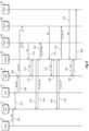
- FIG. 2 shows the operation of the communications system 1 according to an embodiment.
- the data source stores the data, in the portions P1 to P9, in the first database 14.
- the key generator 16 communicates with the first database 14 and generates keys which are associated with the data. To do so, the key generator 16 generates a plurality of sets of the data portions. Each set identifies one or more of the data portions. The sets may be overlapping, at least in part, such that at least one data portion is identified in two or more sets.
- a table showing an exemplary distribution of the data into sets S 1 and S2 is shown below. Set Portions S1 P2, P3, P6 S2 P1-P5, P7
- data portions P2 and P3 are identified in both sets S1 and S2.
- Data portions P8 and P9 are not identified in either of sets S1 and S2 - a method of accessing these portions will be described below and with reference to Figure 3 .
- the key generator 16 may retrieve and process all or part of the portions P1 to P9 within the first database 14. A number of different methods by which this may be done will be described in detail below, but for conciseness will not be described here.
- the key generator 16 uses a one-way function to generate a plurality of keys. Each key is associated with a respective set, as is shown in the following table. Key Set Portions K1 S1 P2, P3, P6 K2 S2 P1-P5, P7
- the key generator 16 stores the keys and information associating the keys with the sets in the second database 18. This data may be stored in, for example, a lookup table.
- the key generator 16 also arranges for the keys to be made available for distribution to one or more requesting parties, such as parties 24A and 24B. This is shown by step 108, where key K1 is made available to party 24A and key K2 to party 24B. In this example, party 24C does not receive a key, for reasons which will be described in more detail below. With reference back to Figure 1 , this distribution of keys may be performed via the first network 22.
- step 110 requesting party 24A transmits a data access request to the access controller 20.
- the data access request comprises the key K1, which had been received by the requesting party 24A in step 108. Having received a data access request the access controller 20 enables access, by the requesting party 24A, to the one or more data portions identified in the set associated with the received key, as will be described in detail with reference to steps 112 to 120.
- the access controller 20 uses the received key K1 to identify the set - in this case set S1 - associated with the received key. This may be done by performing a lookup in the second database 18. Data identifying the set and/or the portions is received by the access controller 20 in step 114. The access controller 20 then, in step 116, retrieves the relevant portions - in this case portions P2, P3 and P6 - from the first database 14. The portions are received by the access controller 20 in step 118 and sent to the requesting party 24A in step 120. Accordingly, access to the portions P2, P3 and P6 is enabled for the requesting party 24A. The requesting party 24A is only able to access the portions P2, P3 and P6; it is unable to access portions other than those associated with the key K1, i.e. portions P1, P4-P5 and P7-P9.
- Similar access requests may be made by requesting party 24B as shown in Figure 2 by steps 122 to 132.
- the difference in these steps is that the key received by the access controller 20 is key K2 (instead of key K1) and accordingly the portions returned to the requesting party 24B are the portions P1-P5 and P7, which are those identified within the set S2 associated with the key K2.
- requesting party 24C has not received a valid key; that is, no key was distributed to requesting party 24C in step 108.
- Requesting party 24C may therefore be assumed to be an attacking party, looking to gain access to the data portions, which is unauthorized.
- the requesting party 24C uses an invalid key K#.
- This invalid key K# may be, for example, a guessed or randomly generated key.
- the request comprising the invalid key is received by the access controller 20 in step 134 and used to perform a lookup in the second database 18 in step 136. However this lookup is unsuccessful as there are no sets or portions associated with the invalid key K#.
- the access controller 20 receives notification from the second database 18 that there are no associated portions in step 138, and consequently the access controller 20 denies requesting party 24C access to any of the data portions. This may include, in step 140, the access controller transmitting a rejection message to the requesting party 24C; however this is not required, and the access controller 20 may simply ignore the request made in step 134 without making a response.
- embodiments are able to efficiently control access to overlapping sets of data portions - i.e. where two sets identify the same data portion.
- a key be compromised - that is the key is known to a party which is not authorised to access the data - the only changes which need to be made are to the association between the keys and the sets. For example, a new key may be generated and associated with the set which was previously associated with the compromised key. The compromised key may then be revoked, deleted or suppressed. This is more efficient than the encryption system described in the background section as no re-encryption is required.
- One-way functions, used to generate the keys, are functions designed such that it is easy to compute the output using the input, but difficult to compute the input using the output. They are known in the art, and therefore will not be described in detail.
- a one-way function (use to generate the keys) is a mathematical function that is significantly easier to compute in one direction (the forward direction) than in the opposite direction (the inverse direction). It might be possible, for example, to compute the function in the forward direction in seconds but to compute its inverse could take months or years, if at all possible.
- a one-way function will give an output that is unpredictable and equally distributed throughout the key space (the key space being the range of possible values which the key may take).
- a third party will be unable to create valid keys to use to access the data, and thus the only source of a valid key is via distribution from the key generator 16.
- This provides improved security to the system as the distribution of the keys can be controlled and used to restrict access to the data and as the key itself provides a means to authenticate the requesting parties and thus control access to the data.
- a key should a key become compromised, only the set of data portions associated with that key are vulnerable to attack, rather than the data as a whole.
- This can also be contrasted to a system where a key merely represents requested data in the clear. Such a system can enable the distribution of data, but cannot prevent an attacking party from changing the form of the request and thereby accessing different data portions.
- a trapdoor one-way function is a one-way function for which the inverse direction is easy given a certain piece of information (the trapdoor), but difficult otherwise.
- public-key cryptosystems may be based on trapdoor one-way functions. The public key gives information about the particular instance of the function; the private key gives information about the trapdoor. Whoever knows the trapdoor can compute the function easily in both directions, but anyone lacking the trapdoor can only perform the function easily in the forward direction. The forward direction is used for encryption and signature verification; the inverse direction is used for decryption and signature generation. determined.
- keys provide a number of advantages over a system which uses, for example, a username/password based authentication system. Firstly, they keys enable a much greater granularity to access control - that is, a given requesting party may be provided with a plurality of keys, each enabling access to different portions of data. This can be illustrated by the following table.
- the data portions represent fields in a database structure.
- the database structure further separates the data into records, each comprising the portions (i.e. fields) P1 to P9. Sets of portions may be created for each record, as shown in the table below.
- a key K1 R1 may be associated with a set S1 R1 , which is in turn associated with the portions P2 R1 , P3 R1 and P6 R1 in the first record R1. Similar keys K1 R2 , K1 R3 , K2 R1 etc. may be created and distributed for other sets of portions in the various records.
- a requesting party may be provided with one, or a combination of, the keys, and thus be provided with a highly controllable access to the data.
- a further advantage is that requesting parties may share keys with other parties, and thereby enable those other parties to access the data portions associated with the shared key. This can be done without having to provide credentials, for example, a full username and password to that other party, which can severely compromise the security of the system, as well as providing the other party with access to everything accessible via that username and password, rather than specific data.
- the keys may have high entropy. That is the one-way function used to generate the key is designed to have a high entropy output.
- Entropy in this context, is a measure of unpredictability or randomness in the generated keys and here relates to the number of equally possible keys which may exist. High entropy in turn means that the number of equally possible keys is sufficiently large to make a brute force attack to find a much smaller number of valid keys impractical.
- the key in a relatively low security system, may be a 16 bit word equating to approximately 65,000 possible keys, and approximately 50 ( ⁇ 2 6 ) keys may be distributed. This gives a ratio of possible to valid keys of approximately one thousand (10 3 or 2 10 ) to 1. In a higher security system, the ratio may be one billion (10 9 or 2 30 ) to 1 or higher.
- the key may be a 64-bit, 128-bit, 256-bit (or higher) number or word, equating to approximately 10 19 (2 64 ), 10 38 (2 128 ), or 10 77 (2 256 ) possible keys.
- a further factor which may be taken into account when determining whether a key length has high enough entropy, relates to the probability of there being a collision between two equal valid keys. This may happen if there are a large number of valid keys, even if the number of possible keys is large.
- the number of valid keys to be used may be estimated, and the key length selected to give an entropy which provides a risk of collision below an acceptable level.
- Sufficient key entropy is one way of mitigating a known attack, referred to as the birthday problem.
- the probability of two valid keys being equal is less than 1%.
- the probability of a collision i.e. there being two equal valid keys
- the probability of finding (e.g. guessing) any valid key will be a factor in determining whether a given key length has sufficiently high entropy for the desired security of the system.
- the nature of the data accessible using the keys may be arranged such that a high probability of finding a valid key is not a problem.
- a collision may provide a party with access to data portions representing a small section of a single video. This may not be seen as a problem, as that party will not have access to the remainder of the video, and thus is provided with little value (i.e. the whole video). Therefore, in such systems, the probability of collisions may be high and yet the key may still have high enough entropy.
- the data portions represent commercially sensitive data, such as financial data
- a party gaining access to even a small quantity of the data may represent a security problem, and thus the probability of collisions must be made significantly smaller for the key to have high enough entropy.
- the one-way function used by the key generator 16 may be a pseudo-random number generator, as are known in the art.
- the key generator 16 may be arranged to generate a random number using an unpredictable input, for example temperature or the movement of the head of a disk drive. This generates a random number - sometimes called a true random number - which is less deterministic than a pseudo-random number.
- Such systems are again known in the art, and use a one-way function to create values which are evenly distributed over a desired range of values.
- the one-way function is sometimes called a randomness extractor. In either case, while the keys will enable access to given data portions, the values taken by the keys will have no direct relationship with the data portions themselves.
- the key generator 16 may use information associated with the data portions as an input to the one-way function. This information may be associated with the data portions within the set of data portions to be associated with the key. The information may comprise at least a part of the content of the data portions, alternatively of additionally, the information may identify the data portions, for example being metadata, portion identifiers, filenames, or the like.
- the one-way function may comprise a hash function.
- the hash function reduces the length of the input information to a desired length, i.e. the length of the keys.
- the hash function will also produce an output with high uniformity meaning that the expected inputs are mapped evenly over the output range. This has the additional effect that a small change in the input will typically result in a large and unpredictable change in the output.
- the one way function may comprise a cryptographic signing function, which may be combined with the hash function mentioned above. Where the two are combined, the hash function may be used on the information, and the hashed result signed.
- the advantage of generating the keys using information associated with the data portions is that the key can serve a dual purpose. That is, the key not only enables a requesting party to access the data portions, but also enables the requesting party to verify that data portions to which access is enabled are genuine. As a consequence, security is enhanced, since any changes to the data portions, between the keys being distributed and the data portions being retrieved, will be detectable.
- all of the data may be used to generate the key, this in turn enables the validity of all of the data to be verified.
- only a part of the data may be used to generate a key - this part may be, for example, more sensitive than other parts of the data.
- the requesting party will be able to verify the integrity of the received data portions by comparing the hash of the information associated with the received data (which was used to generate the key) with the key itself. If the two match, then the received data portions may be taken as genuine, and/or the requestor has assurance that the data has not been accidentally or maliciously modified since the key was generated. To enhance security, the key may be signed. In which case the receiving party may not only determine that the data is genuine, but may confirm that the correct entity generated the key, i.e. the system offers the requester assurance of non-repudiation. The use of e.g. public/private keys to sign data and to verify data is known and will not be described in detail.
- Further embodiments may use information associated with the portions, without providing any ability for verifying the integrity of the data.
- the data itself may be used as the input to a one-way function merely to increase the unpredictability of the keys generated.
- the information associated with the data forms the unpredictable (or at least less predictable) input in the true random number generator described above.
- any number of one-way functions may be used, so that an evenly distributed output is produced.
- each given set of data portions may be associated with only a single key. Thus, if two requesting parties are to be allowed access to that set of data portions, they will receive the same key. This may be desirable in a system where keys are intended to be shared between requesting parties, and enables the number of keys to be kept low.
- each requesting party may be desirable to provide with different keys, irrespective of what data portions are to be accessed using those keys.
- an additional value sometimes called a salt value, may be included as an input into the one-way function. This enables two different keys to be created for the same set of data portions. Since the keys are different, the requesting party making the request can be identified, meaning that if an unauthorized request is made using a valid key, the authorized requesting party from which the key was obtained can be identified.
- the requesting parties may need to know the relevant salt values (e.g. if integrity checks on the data are required) - otherwise the requesting party will be unable to generate a valid hash.
- the salt values may be made available with the keys, for example, the salt values and the keys may be distributed together.
- the salt values may be made publically available in a lookup table.
- a pre-shared secret value or values may be specific to a given requesting party - in other words, a prior arrangement ensures that the requesting party knows what pre-shared secret value or values are to be used (may be in a similar manner as a salt value).
- the salt values may be stored with the data portions, for example by creating additional data portions representing the salt values.
- two different keys here K1a and K1b
- access the same set portions of the original data portions P2, P3 and P6.
- the portions of data are augmented with salt value portions, Pa and Pb.
- the keys generated using the data portions are different. This is summarized in the table below. It will be understood that the validation of the received data is possible without modification as the received portions will include a salt values Pa or Pb.
- the keys may be distributed via first network 22, while the access requests, and the portions of data sent in response, may be transmitted through a second network 26.
- This provides the advantage that the first network 22, used to distribute the keys, may be provided with a higher level of security in comparison to the second network 26.
- the first network 22 may be replaced by an alternative method of providing the keys - for example physical transportation of the keys on a physical media. Either way, the keys may be kept relatively secure, while the access to the data portions is enabled using a relatively less secure network.
- either or both of the first and second networks 22 and 26 may be cryptographically protected using e.g. SSL or TLS.
- a further advantage is that embodiments facilitate access to data using an existing, or legacy, protocol, when that existing protocol is constrained in terms of the amount of data that can be transmitted, and it is inconvenient or expensive to modify the protocol.
- the first network described above may support such a first protocol.
- the keys which are relatively small in terms of number of bytes, may be distributed using this first protocol, while the data portions may be transmitted via a second protocol, which is unconstrained in terms of type and amount of data that can be transmitted. This ensures backward compatibility, as devices can still access the data portions - via the keys that are transmitted over the first protocol.
- the keys and associated sets of portions may be stored in a number of formats within the first database 14 and second database 18.
- the keys may be directly associated with portions as follows. Thus information explicitly identifying the sets does not need to be stored.
- a relational database structure may be used, for example a first table may associate keys with sets: Key Set K1 S1 K2 S2 and a second table may associate sets with portions: Set Portions S1 P2, P3, P6 S2 P1-P5, P7
- the second table, associating the sets with data portions may be stored with the data portions themselves, i.e. in the first database 14.
- the responses from the second database in steps 114 and 126 above may contain an identification of a set, if a key is valid, and the requests in steps 116 and 128 may be for a given set of data.
- some embodiments may allow the requesting parties to identify portions when making a request. Therefore, for example, in step 110, the requesting party 24A may provide key K1, and request only portion P2. As a result, in step 120, the access controller 20 may provide only data portion P2 to the requesting party 24A.
- Figure 2 shows a first method of enabling access to data using keys
- Figures 3 to 5 will be used to illustrate variations which may be incorporated into, or substituted for, the method described above.
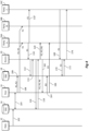
- Figure 3 illustrates a method which utilising combined keys. This method will be described in detail below, but in overview the method enables certain portions to be access only by two or more parties acting together. This increases security for more sensitive data as both parties are required to provide their keys to enable access.
- Steps 102 to 108 the generation of sets of data portions and association with keys progresses in a similar manner to that described above.
- three keys may be created as follows: Key Set Portions K1 S1 P2, P3, P6 K2 S2 P1-P5, P7 K3 S3 P8, P9
- the third key, K3 is based on a combination of the first and second keys.
- the third key may be generated, for example, as a function of the first and second keys such as a concatenation or a bitwise exclusive-or (XOR) of the first and second keys. It will be appreciated that other functions, including one-way functions, may be used.
- the third key may be generated, and then itself used to generate the first and second keys - for example by splitting the third key into parts, or by calculating the first and second keys using the third. Whichever method is used, the third key can be derived from knowledge of the first and second keys.
- the third key is associated with a third set S3 which identifies portions P8 and P9.
- the first and second keys K1 and K2 are associated with sets S1 and S2 respectively; however this is not a requirement, and one or both of the first and second keys K1 and K2 may not be associated with any set of data portions.
- the third key provides access to a particular set of data portions, it does not have to be distributed to recipients. Instead it represents a particular combination of other keys; these other keys are distributed to recipients and these keys are required by the access controller 20 for the access controller 20 to return data portions relating to this third key.
- the first and second keys can be considered to function as surrogates for access to a particular data set associated with the third key.
- the first and second keys are made available for distribution in step 108.
- key K1 is made available to requesting party 24A
- key K2 is made available to requesting party 24B.
- the third key is not distributed, which is to say that no requesting party will receive the third key.
- the requesting parties 24A and 24B cooperate to combine the keys and to request access using the combined keys.
- One method of doing this is shown in Figure 3 .
- the access controller 20 has identified that access will be requested using multiple keys. This may be in response to one of the parties indicating that a multi-key request is being made in a given request, or by the request identifying data portions which can only be accessed using multiple keys.
- step 146 the requesting party 24A sends a request comprising the key K1 to the access controller 20.
- step 148 the requesting party 24B also sends a request, this one comprising the key K2, to the access controller 20.
- the access controller may, in step 150, generate the third key K3 using the first and second keys K1 and K2.
- This third key K3 is then sent to the second database 18 in an analogous step to steps 112 and 124 above.
- the access controller in step 154 receives data identifying the set S3 or the portions thereof (portions P8 and P9) from the second database 18.
- the access controller in step 156 then retrieves the portions P8 and P9 from the first database 14, and provides the portions to one or both of the requesting parties 24A and 24B. Therefore, only by combining the keys can the two requesting parties gain access to the portions P8 and P9.
- the requesting parties may act independently and retrieve any portions which are associated with the individual keys distributed to the parties. This is shown in Figure 3 in steps 110 to 120 which are the same as steps 110 to 120 above, and show the first requesting party 24A accessing portions P2, P3 and P6 using the key K1. As mentioned above, the keys K1 and K2 do not have to be associated with any sets of data portions. Accordingly, in an alternative embodiment, a request using key K1 may result in a rejection as for an invalid key, described in steps 134 to 140 above.
- a key may be requested from one or other of the requesting parties by the access controller 20.
- a first requesting party e.g. requesting party 24A
- the access controller 20 may communicate with requesting party 24B to request the key K2.
- the requesting party 24A may request access to e.g. portions P8 and/or P9, and the access controller may store data enabling it to contact the second requesting party 24B to request the appropriate key.
- Other methods of communicating between the parties so that both provide keys will be evident to the skilled person.
- a second requesting party may be provided with the ability to allow or refuse access for a first party (or vice versa).
- the second requesting party may be an administrator who has the ability to grant or refuse access for any one of a number of member parties.
- a single administrative key may grant access to different sets of data portions when combined with different member keys.
- a member key may be considered as an identifier of a given set of data portions, and the administrator key an access control key for those data portions.
- the function used to combine the keys may be arranged such that, even though the requesting parties 24A and 24B have knowledge of the individual keys K1 and K2, these parties will be unable to generate the key K3 if they are only in receipt of one key.
- This level of control may be enforced by using a function such as a one-way function within the access controller 20 to generate the key K3. This has the advantage that two parties need to provide the keys K1 and K2 individually to the access controller 20 to gain access to the data portions P8 and P9.
- the key K3 may be a calculated combination of keys K1 and K2.
- one or both of the requesting parties 24A and 24B may receive a key from the other.
- the requesting party that receives a key from another party may then combine the keys to produce the key K3, which is used in a request for access to data. That party will then be able to access the data portions P8 and P9 as if that party had been originally provided with the key K3 in the distribution.
- Such embodiments provide the advantage that only a single access request, using what amounts to key K3, is required to access data, and avoids the access controller 20 making a request to another party for a key. It will be appreciated that the system used may be tailored in dependence on the intended purpose of the system.
- the access controller 20 and second database 18 may be arranged such that an access request or requests comprising multiple keys may lead to access being granted without actually requiring determination of an intermediary key, i.e. key K3.
- This has the advantage that the number of keys is reduced; however, the use of a determined key, such as key K3, provides the advantage that the arrangement of the database 18 is simplified, since the database 18 will not have to store any additional information indicating that multiple keys are required.
- the keys to be combined may be sent to different requesting parties. However this is not a requirement, and the keys may be sent to a single requesting party.
- the keys may be sent using different communications systems - e.g. one key is sent via a SMS, the other via email - or at different points in time.
- embodiments can be used to enable access to a party in more complex scenarios.
- keys may only be used a limited number of times. Two examples of such embodiments are described in Figures 4 and 5 . In both examples, a given key may be used only once; however this is not a requirement, and a given key may be used multiple times, albeit still a limited number of times.
- a first example is shown in Figure 4 .
- the portions are stored in the first database 14 and the keys are distributed.
- the requesting party 24C does not receive a key.
- the requesting party 24C has compromised the system of requesting party 24A.
- the requesting party 24C is able to acquire a copy of the key K1 when it is used by the requesting party 24A.
- steps 110 and 110' the requesting party 24A sends a request, comprising the key K1, to the access controller 20.
- the key K1 is received, in step 110' by the requesting party 24C.
- Steps 112 to 120 follow the steps of the same number described above, and result in the requesting party 24A being able to access the portions P2, P3 and P6.
- the access controller sends a message to the key generator 16 informing the key generator 16 that the key K1 has been used. This is shown as step 162.
- the key generator In response to the message in steps 162, the key generator generates a new key to be associated with the set S1.
- the second database 18 is updated to reflect that the key K4 now associated with the set S1, and thus with portions P2, P3 and P6.
- the key K1 is revoked and may be removed from, or supressed within, the second database 18.
- the key generator 16 makes the new key K4 available for distribution to the requesting party 24A, as shown by step 166.
- key K1 is replaced by key K4.
- the key K4 may be generated using e.g. a different salt value to key K1, as was described above. If the salt value is to be stored with the data, i.e. as a portion (e.g. Pa and Pb) then the data may be modified to contain the new salt value.
- the new key K4 may be generated prior to the accessing of the data portions by the requesting party 24A.
- the new key may consequently be made available to the requesting party along with the data portions.
- steps 120 and 166 may be combined.
- step 110' the requesting party 24C has gained access to the key K1.
- the requesting party 24C therefore attempts to use this key to access the data by sending a request, comprising the key K1, to the access controller in step 168.
- the key K1 is not valid, and consequently the request is rejected.
- the method above may be used to improve the security of the system, and reduce the opportunity for attacking parties to gain access to the stored data using intercepted or stolen keys.
- the replacement of keys may be used in combination with the system described above where multiple keys are required for access to certain sets of data portions to replace a used key.
- only a subset of the keys used for a multi-key request may be replaced. For example, in the embodiment above, each request may result in the administrator key being replaced, but not in the user key being replaced.
- FIG. 5 A further method, in which keys are only used once, is shown in Figure 5 .
- This method differs from that shown in Figure 4 in that a plurality of keys, each associated with a single set, are generated initially and distributed together. This is represented by steps 106' and 108', where keys K1.1, K1.2, ... K1.N are all associated with set S1 and are distributed to the requesting parties 24A and 24B. Each of the keys K1.1 to K1.N may be generated using a different salt value.
- the key K1.1 is used by the requesting party 24A to request access to the data portions associated with that key, i.e. the data portions in set S1. As before, access to these data portions is granted in step 120. However, following step 120, the access controller 20, in step 176, sends a message to the second database 18 to revoke, delete or suppress the key K1.1 as it has now been used.
- step 178 a further attempt is made to request the data portions in set S1 corresponding to the keys K1.1, K1.2 etc.
- both requesting parties 24A and 24B have been provided with the same set of keys.
- requesting party 24B is unaware that the key K1.1 has been used. Therefore in step 178 the requesting party 24B requests access to the data using the key 1.1.
- this request is handled in a similar manner to the request described in steps 134 to 140 above, and is rejected. It will be appreciated that this would be how any further request using the key K1.1 would be handled - i.e. if the request had come from requesting party 24C who had gained the key K1.1 by intercepting it from requesting party 24A as described in step 110' above.
- step 122 where the key K1.2 is used in a request.
- step 132 may be followed by the key K1.2 being deleted or suppressed in the second database 18, as shown by step 186.
- any number of keys may be issued, and any party may have to make request using a much larger number of keys before one is accepted. It will be understood that any given requesting party may keep a record of keys which have been used. Therefore, for example, should the requesting party 24A make a further request for the data, it would make a first attempt with key K1.2, as it will know that key K1.1 has been used already. It will be appreciated that this request would be rejected, as the key K1.2 has been used by requesting party 24B, and therefore the requesting party would have to use a key K1.3 etc. until a request is granted.
- Embodiments described above may be combined with other forms of access control, for example authentication using a username and password, to increase the security of the system as a whole.
- a key may be associated with a username, and thus access will only be granted to an authorized user who is in possession of a key associated with that user.
- a single key is provided at a time to a given requesting party.
- a single key may be provided to multiple parties.
- multiple keys may be associated with a single set, the key being provided to multiple requesting parties. This enables the parties to access the same data, but for a log to be maintained over which party has made a given access request.
- a given portion of data may be accessible using different combinations of keys.
- a first requesting party may request access to data using a first key.
- the access controller may request a second key from one of a plurality of second requesting parties.
- a response (containing a key) from any one of the second requesting parties will grant the first party access to the data.
- the keys may be used as a method to confirm an access request.
- a key may have a validity for only a certain period of time, after which it is revoked, and a replacement distributed.
- time based revocation may be combined with limited use revocation, meaning that once a key is used once, it is valid for a given period of time, during which it may be used any number of times, and after which it is revoked.
- the access system 10, or the nodes or elements 12 to 20, may comprise computerised hardware as is known in the art.
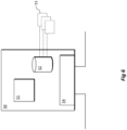
- an exemplary computerised system 50 capable of performing the method steps described above, will now be described with reference to Figure 6 .
- This computerised system may be used to perform the function of the access system 10 as a whole, or a number of the computerised systems 50 may be used, each performing the function of one or more of the nodes 12 to 20 described above.
- the computerised system 50 comprises a processing system 51, such as a CPU, or an array of CPUs.
- the processing system 51 is connected to a memory 52, such as volatile memory (e.g. RAM) or non-volatile memory, for example a solid state (SSD) memory or hard disk drive memory.
- the memory 52 stores computer readable instructions 53.
- the system 50 may also comprise an interface 54, capable of transmitting and/or receiving data from other network nodes.
- the processing system 51 may retrieve the computer instructions 53 from memory 52 and execute these instructions whereby to perform the steps described above. In so doing, the processing system 51 may cause the interface to transmit or receive data as required. This data may itself be stored in memory 52, and retrieved as required - for example to be transmitted via the interface.
Description
- The present invention relates to apparatus, systems and methods for enabling access to data, and in particular to enabling access to data by a plurality of requesting parties.
- In many communications systems it is desirable to control access to data. In particular it is desirable to have a system in which different requesting parties are allowed to access certain data portions within a given block of data while being prevented from accessing other data portions. Moreover, it is desirable to allow different parties access to the same data portions of data, while not, for example, giving two parties access to all the same data portions; that is, parties are allowed overlapping, but not necessarily identical, access.
- One example of a system to provide this is described in
US 2005/0180573 . In this example a block of data is divided into portions. Each portion of the data is then encrypted using a different portion specific key. Requesting parties are then provided with a party specific key, which can be used to derive or decrypt portion specific keys. The party specific keys are arranged such that a given party is only able to acquire portion specific keys corresponding to portions of the data to which the party is allowed access. This enables a requesting party to decrypt, and thus access, the portions of the data to which that party is allowed access. - However, this system comes with a number of drawbacks. For example, a lost key, or removal of access rights of a given requesting party, means that all portions of the data to which a given party was previously allowed access have to be re-encrypted. In addition, this system requires any computerised equipment used by the parties to be capable of decrypting the data adding overheads to the overall system.
-
WO 99/38902 -
US 2009/0157740 discusses a content addressable storage manager that includes a content identifier generator which generates a content identifier for each data element stored in the content storage. -
US 2013/0198475 discusses content addressable stores based on sibling groups. Consequently, there is a need for an improved system for enabling access to data. - The aforementioned problem is solved by the features of the independent claims. Further embodiments are the subject-matter of the dependent claims.
- Systems, apparatus and methods will now be described as embodiments, by way of example only, with reference to the accompanying figures in which:
-
Figure 1 shows a schematic diagram of a communications system in which embodiments of the invention may be practised; -
Figure 2 illustrates a method according to an embodiment; -
Figure 3 illustrates a further method utilising combined keys according to an embodiment; -
Figure 4 illustrates a method according to an embodiment in which a key can be used a limited number of times; -
Figure 5 illustrates a further method according to an embodiment in which multiple keys are generated, each being useable a limited number of times; -
Figure 6 shows a schematic diagram of a network node which may be used in embodiments of the invention. - Some parts, components and/or steps of the embodiments appear in more than one Figure; for the sake of clarity the same reference numeral will be used to refer to the same part, component or step in all of the Figures.
-
Figure 1 shows acommunications system 1 in which a number of requesting parties may access data stored in a data store, such as a database. Within the communications system, the data is stored within, and access to the data is controlled by, anaccess system 10. - The
access system 10 comprises a number of nodes orelements data source 12, which receives or generates data to be stored and subsequently accessed. Thedata source 12 is connected to afirst database 14. Akey generator 16 is connected to thefirst database 14, and is additionally connected to asecond database 18. Anaccess controller 20 is connected to the first andsecond databases - The
key generator 16 is connected to a number of requestingparties first network 22. Theaccess controller 20 is also connected to the requestingparties second network 26. - The
access system 10 may be a single device. Accordingly thenodes databases access system 10 may be distributed, for example by being in the cloud - as such some or all of thenodes - The requesting
parties access system 10; accordingly thenetworks networks networks - The operation of the
communications system 1 described above inFigure 1 will now be described with reference toFigures 2 to 5 . In these Figures, steps which are the same, or at least analogous, will be provided with the same reference numerals. It is assumed that, preceding the steps shown inFigures 2 to 5 , appropriate data has been generated at, or received by, thedata source 12. This data may take any number of forms, for example being documents, transaction data, media such as audio or video and/or metadata. The data may be received in data portions, for example individual files, media sections or fields and records in a structured or tabulated form of the data. Alternatively or additionally, the data may be separated into suitable data portions by thedata source 12. The data portions will be provided with references P1 to P9 in the examples described below. -
Figure 2 shows the operation of thecommunications system 1 according to an embodiment. Instep 102, the data source stores the data, in the portions P1 to P9, in thefirst database 14. Following that, instep 104, thekey generator 16 communicates with thefirst database 14 and generates keys which are associated with the data. To do so, thekey generator 16 generates a plurality of sets of the data portions. Each set identifies one or more of the data portions. The sets may be overlapping, at least in part, such that at least one data portion is identified in two or more sets. A table showing an exemplary distribution of the data intosets S 1 and S2 is shown below.Set Portions S1 P2, P3, P6 S2 P1-P5, P7 - Here, the data portions P2 and P3 are identified in both sets S1 and S2. Data portions P8 and P9 are not identified in either of sets S1 and S2 - a method of accessing these portions will be described below and with reference to
Figure 3 . - To generate the sets, the
key generator 16 may retrieve and process all or part of the portions P1 to P9 within thefirst database 14. A number of different methods by which this may be done will be described in detail below, but for conciseness will not be described here. - Having generated the plurality of sets, the
key generator 16 then uses a one-way function to generate a plurality of keys. Each key is associated with a respective set, as is shown in the following table.Key Set Portions K1 S1 P2, P3, P6 K2 S2 P1-P5, P7 - Subsequently, in
step 106, thekey generator 16 stores the keys and information associating the keys with the sets in thesecond database 18. This data may be stored in, for example, a lookup table. - The
key generator 16 also arranges for the keys to be made available for distribution to one or more requesting parties, such asparties step 108, where key K1 is made available toparty 24A and key K2 to party 24B. In this example,party 24C does not receive a key, for reasons which will be described in more detail below. With reference back toFigure 1 , this distribution of keys may be performed via thefirst network 22. - The above describes the creation and distribution of keys. The following will describe how these keys may be used to enable access to data for the requesting parties.
- In
step 110, requestingparty 24A transmits a data access request to theaccess controller 20. The data access request comprises the key K1, which had been received by the requestingparty 24A instep 108. Having received a data access request theaccess controller 20 enables access, by the requestingparty 24A, to the one or more data portions identified in the set associated with the received key, as will be described in detail with reference tosteps 112 to 120. - In
step 112, theaccess controller 20 uses the received key K1 to identify the set - in this case set S1 - associated with the received key. This may be done by performing a lookup in thesecond database 18. Data identifying the set and/or the portions is received by theaccess controller 20 instep 114. Theaccess controller 20 then, instep 116, retrieves the relevant portions - in this case portions P2, P3 and P6 - from thefirst database 14. The portions are received by theaccess controller 20 instep 118 and sent to the requestingparty 24A instep 120. Accordingly, access to the portions P2, P3 and P6 is enabled for the requestingparty 24A. The requestingparty 24A is only able to access the portions P2, P3 and P6; it is unable to access portions other than those associated with the key K1, i.e. portions P1, P4-P5 and P7-P9. - Similar access requests may be made by requesting
party 24B as shown inFigure 2 bysteps 122 to 132. The difference in these steps is that the key received by theaccess controller 20 is key K2 (instead of key K1) and accordingly the portions returned to the requestingparty 24B are the portions P1-P5 and P7, which are those identified within the set S2 associated with the key K2. - As noted above, requesting
party 24C has not received a valid key; that is, no key was distributed to requestingparty 24C instep 108. Requestingparty 24C may therefore be assumed to be an attacking party, looking to gain access to the data portions, which is unauthorized. In this example, the requestingparty 24C uses an invalid key K#. This invalid key K# may be, for example, a guessed or randomly generated key. The request comprising the invalid key is received by theaccess controller 20 instep 134 and used to perform a lookup in thesecond database 18 instep 136. However this lookup is unsuccessful as there are no sets or portions associated with the invalid key K#. Theaccess controller 20 receives notification from thesecond database 18 that there are no associated portions instep 138, and consequently theaccess controller 20 denies requestingparty 24C access to any of the data portions. This may include, instep 140, the access controller transmitting a rejection message to the requestingparty 24C; however this is not required, and theaccess controller 20 may simply ignore the request made instep 134 without making a response. - The above describes a first method of enabling access to data according to embodiments. By generating the sets, and associating the set with the keys, embodiments are able to efficiently control access to overlapping sets of data portions - i.e. where two sets identify the same data portion. Moreover, should a key be compromised - that is the key is known to a party which is not authorised to access the data - the only changes which need to be made are to the association between the keys and the sets. For example, a new key may be generated and associated with the set which was previously associated with the compromised key. The compromised key may then be revoked, deleted or suppressed. This is more efficient than the encryption system described in the background section as no re-encryption is required.
- One-way functions, used to generate the keys, are functions designed such that it is easy to compute the output using the input, but difficult to compute the input using the output. They are known in the art, and therefore will not be described in detail.
- A one-way function (use to generate the keys) is a mathematical function that is significantly easier to compute in one direction (the forward direction) than in the opposite direction (the inverse direction). It might be possible, for example, to compute the function in the forward direction in seconds but to compute its inverse could take months or years, if at all possible. A one-way function will give an output that is unpredictable and equally distributed throughout the key space (the key space being the range of possible values which the key may take).
- As a consequence of using a one-way function, a third party will be unable to create valid keys to use to access the data, and thus the only source of a valid key is via distribution from the
key generator 16. This provides improved security to the system as the distribution of the keys can be controlled and used to restrict access to the data and as the key itself provides a means to authenticate the requesting parties and thus control access to the data. Moreover, should a key become compromised, only the set of data portions associated with that key are vulnerable to attack, rather than the data as a whole. This can also be contrasted to a system where a key merely represents requested data in the clear. Such a system can enable the distribution of data, but cannot prevent an attacking party from changing the form of the request and thereby accessing different data portions. - Examples of appropriate one-way functions include random or pseudorandom number generators, hash functions (the application of which will be described in more detail below), and so-called "trapdoor" one-way functions. A trapdoor one-way function is a one-way function for which the inverse direction is easy given a certain piece of information (the trapdoor), but difficult otherwise. For example, public-key cryptosystems may be based on trapdoor one-way functions. The public key gives information about the particular instance of the function; the private key gives information about the trapdoor. Whoever knows the trapdoor can compute the function easily in both directions, but anyone lacking the trapdoor can only perform the function easily in the forward direction. The forward direction is used for encryption and signature verification; the inverse direction is used for decryption and signature generation. determined.
- The use of keys provides a number of advantages over a system which uses, for example, a username/password based authentication system. Firstly, they keys enable a much greater granularity to access control - that is, a given requesting party may be provided with a plurality of keys, each enabling access to different portions of data. This can be illustrated by the following table. Here the data portions represent fields in a database structure. The database structure further separates the data into records, each comprising the portions (i.e. fields) P1 to P9. Sets of portions may be created for each record, as shown in the table below.
Group ID P1 P2 P3 P4 P5 P6 P7 P8 P9 R1 P1R1 P2R1 P3R1 P4R1 P5R1 P6R1 P7R1 P8R1 P9R1 R2 P1R2 P2R2 P3R2 P4R2 P5R2 P6R2 P7R2 P8R2 P9R2 R3 P1R3 P2R3 P3R3 P4R3 P5R3 P6R3 P7R3 P8R3 P9R3 - Therefore to continue the example above, a key K1R1 may be associated with a set S1R1, which is in turn associated with the portions P2R1, P3R1 and P6R1 in the first record R1. Similar keys K1R2, K1R3, K2R1 etc. may be created and distributed for other sets of portions in the various records. A requesting party may be provided with one, or a combination of, the keys, and thus be provided with a highly controllable access to the data.
- A further advantage is that requesting parties may share keys with other parties, and thereby enable those other parties to access the data portions associated with the shared key. This can be done without having to provide credentials, for example, a full username and password to that other party, which can severely compromise the security of the system, as well as providing the other party with access to everything accessible via that username and password, rather than specific data.
- The keys may have high entropy. That is the one-way function used to generate the key is designed to have a high entropy output. Entropy, in this context, is a measure of unpredictability or randomness in the generated keys and here relates to the number of equally possible keys which may exist. High entropy in turn means that the number of equally possible keys is sufficiently large to make a brute force attack to find a much smaller number of valid keys impractical.
- For example, in a relatively low security system, the key may be a 16 bit word equating to approximately 65,000 possible keys, and approximately 50 (~26) keys may be distributed. This gives a ratio of possible to valid keys of approximately one thousand (103 or 210) to 1. In a higher security system, the ratio may be one billion (109 or 230) to 1 or higher. For example the key may be a 64-bit, 128-bit, 256-bit (or higher) number or word, equating to approximately 1019 (264), 1038 (2128), or 1077 (2256) possible keys. In such a system, even if approximately one billion (109 or 230) keys are distributed, the ratio of possible to valid keys will be in excess of 1010 (~234) to 1, 1029 (~298) to 1 and 1068 (~2226) to 1 respectively. It will be appreciated that factors, such as the algorithm used to generate the keys, the number of requests which can be processed, the number of keys which are to be distributed and the capabilities of the devices requesting the data for handling large keys will determine whether a given key length has high enough entropy for the design purposes of the system.
- A further factor, which may be taken into account when determining whether a key length has high enough entropy, relates to the probability of there being a collision between two equal valid keys. This may happen if there are a large number of valid keys, even if the number of possible keys is large. The number of valid keys to be used may be estimated, and the key length selected to give an entropy which provides a risk of collision below an acceptable level.
- Sufficient key entropy is one way of mitigating a known attack, referred to as the birthday problem. For example, in a system using 64-bit keys, if approximately 100 million (108 or 227) keys are valid then the probability of two valid keys being equal is less than 1%. However, if 100 times that number of keys, i.e. 10 billion keys (1010 or 233), are valid, the probability of a collision (i.e. there being two equal valid keys) is greater than 99%. Depending on the nature of the system, how the keys are generated and the relationship between the keys and the data, this may or may not be a problem. Nevertheless, the probability of finding (e.g. guessing) any valid key, will be a factor in determining whether a given key length has sufficiently high entropy for the desired security of the system.
- In some embodiments, for example, the nature of the data accessible using the keys may be arranged such that a high probability of finding a valid key is not a problem. For example, where the keys are used to control access to multimedia such as video, a collision may provide a party with access to data portions representing a small section of a single video. This may not be seen as a problem, as that party will not have access to the remainder of the video, and thus is provided with little value (i.e. the whole video). Therefore, in such systems, the probability of collisions may be high and yet the key may still have high enough entropy. By contrast, if the data portions represent commercially sensitive data, such as financial data, then a party gaining access to even a small quantity of the data may represent a security problem, and thus the probability of collisions must be made significantly smaller for the key to have high enough entropy.
- The one-way function used by the
key generator 16 may be a pseudo-random number generator, as are known in the art. Alternatively thekey generator 16 may be arranged to generate a random number using an unpredictable input, for example temperature or the movement of the head of a disk drive. This generates a random number - sometimes called a true random number - which is less deterministic than a pseudo-random number. Such systems are again known in the art, and use a one-way function to create values which are evenly distributed over a desired range of values. In this context, the one-way function is sometimes called a randomness extractor. In either case, while the keys will enable access to given data portions, the values taken by the keys will have no direct relationship with the data portions themselves. - In the alternative, therefore, to generate the keys, the
key generator 16 may use information associated with the data portions as an input to the one-way function. This information may be associated with the data portions within the set of data portions to be associated with the key. The information may comprise at least a part of the content of the data portions, alternatively of additionally, the information may identify the data portions, for example being metadata, portion identifiers, filenames, or the like. - Where the keys are generated using information associated with the data portions, the one-way function may comprise a hash function. The hash function reduces the length of the input information to a desired length, i.e. the length of the keys. Typically the hash function will also produce an output with high uniformity meaning that the expected inputs are mapped evenly over the output range. This has the additional effect that a small change in the input will typically result in a large and unpredictable change in the output.
- In embodiments, the one way function may comprise a cryptographic signing function, which may be combined with the hash function mentioned above. Where the two are combined, the hash function may be used on the information, and the hashed result signed.
- The advantage of generating the keys using information associated with the data portions (for example identifying information such as metadata, or the actual content of the data portions themselves) is that the key can serve a dual purpose. That is, the key not only enables a requesting party to access the data portions, but also enables the requesting party to verify that data portions to which access is enabled are genuine. As a consequence, security is enhanced, since any changes to the data portions, between the keys being distributed and the data portions being retrieved, will be detectable.
- In embodiments, all of the data may be used to generate the key, this in turn enables the validity of all of the data to be verified. However in alternative embodiments, only a part of the data may be used to generate a key - this part may be, for example, more sensitive than other parts of the data.
- Where only a hash is used, the requesting party will be able to verify the integrity of the received data portions by comparing the hash of the information associated with the received data (which was used to generate the key) with the key itself. If the two match, then the received data portions may be taken as genuine, and/or the requestor has assurance that the data has not been accidentally or maliciously modified since the key was generated. To enhance security, the key may be signed. In which case the receiving party may not only determine that the data is genuine, but may confirm that the correct entity generated the key, i.e. the system offers the requester assurance of non-repudiation. The use of e.g. public/private keys to sign data and to verify data is known and will not be described in detail.
- Further embodiments may use information associated with the portions, without providing any ability for verifying the integrity of the data. For example, the data itself may be used as the input to a one-way function merely to increase the unpredictability of the keys generated. In effect the information associated with the data forms the unpredictable (or at least less predictable) input in the true random number generator described above. In such cases, any number of one-way functions may be used, so that an evenly distributed output is produced.
- In some embodiments, it may be desirable to have each given set of data portions associated with only a single key. Thus, if two requesting parties are to be allowed access to that set of data portions, they will receive the same key. This may be desirable in a system where keys are intended to be shared between requesting parties, and enables the number of keys to be kept low.
- However, in the alternative, it may be desirable to provide each requesting party with different keys, irrespective of what data portions are to be accessed using those keys. In such embodiments an additional value, sometimes called a salt value, may be included as an input into the one-way function. This enables two different keys to be created for the same set of data portions. Since the keys are different, the requesting party making the request can be identified, meaning that if an unauthorized request is made using a valid key, the authorized requesting party from which the key was obtained can be identified.
- If the keys are to be used to validate the data portions (see above) and are generated using salt values, the requesting parties may need to know the relevant salt values (e.g. if integrity checks on the data are required) - otherwise the requesting party will be unable to generate a valid hash. In this case the salt values may be made available with the keys, for example, the salt values and the keys may be distributed together. In other embodiments, the salt values may be made publically available in a lookup table.
- Alternatively, a pre-shared secret value or values may be specific to a given requesting party - in other words, a prior arrangement ensures that the requesting party knows what pre-shared secret value or values are to be used (may be in a similar manner as a salt value).
- In yet further embodiments, the salt values may be stored with the data portions, for example by creating additional data portions representing the salt values. In the following example, two different keys (here K1a and K1b), access the same set portions of the original data, portions P2, P3 and P6. However in each case, the portions of data are augmented with salt value portions, Pa and Pb. As a consequence, the keys generated using the data portions are different. This is summarized in the table below. It will be understood that the validation of the received data is possible without modification as the received portions will include a salt values Pa or Pb.
Key Salt Value Portions K1a Pa P2, P3, P6, Pa K1b Pb P2, P3, P6, Pb - As mentioned above, the keys may be distributed via
first network 22, while the access requests, and the portions of data sent in response, may be transmitted through asecond network 26. This provides the advantage that thefirst network 22, used to distribute the keys, may be provided with a higher level of security in comparison to thesecond network 26. In some embodiments, thefirst network 22 may be replaced by an alternative method of providing the keys - for example physical transportation of the keys on a physical media. Either way, the keys may be kept relatively secure, while the access to the data portions is enabled using a relatively less secure network. In embodiments either or both of the first andsecond networks - A further advantage is that embodiments facilitate access to data using an existing, or legacy, protocol, when that existing protocol is constrained in terms of the amount of data that can be transmitted, and it is inconvenient or expensive to modify the protocol. For example, the first network described above may support such a first protocol. The keys, which are relatively small in terms of number of bytes, may be distributed using this first protocol, while the data portions may be transmitted via a second protocol, which is unconstrained in terms of type and amount of data that can be transmitted. This ensures backward compatibility, as devices can still access the data portions - via the keys that are transmitted over the first protocol.
- It will be appreciated that the keys and associated sets of portions may be stored in a number of formats within the
first database 14 andsecond database 18. For example, in one embodiment, the keys may be directly associated with portions as follows. Thus information explicitly identifying the sets does not need to be stored.Key Portions K1 P2 K1 P3 K1 P6 K2 P1 K2 P2 K2 P3 K2 P4 K2 P5 K2 P7 - In other embodiments, a relational database structure may be used, for example a first table may associate keys with sets:
Key Set K1 S1 K2 S2 Set Portions S1 P2, P3, P6 S2 P1-P5, P7 - This latter structure provides the advantage that only a single field in a single table needs to be modified if a key is compromised or needs to be revoked. Equally when a new key is issued, only a single record needs to be updated. In some embodiments, the second table, associating the sets with data portions may be stored with the data portions themselves, i.e. in the
first database 14. In such cases, the responses from the second database insteps steps - While in the above method, a given request resulted in the provision of all data portions associated with the key provided in the request, some embodiments may allow the requesting parties to identify portions when making a request. Therefore, for example, in
step 110, the requestingparty 24A may provide key K1, and request only portion P2. As a result, instep 120, theaccess controller 20 may provide only data portion P2 to the requestingparty 24A. - While
Figure 2 shows a first method of enabling access to data using keys,Figures 3 to 5 will be used to illustrate variations which may be incorporated into, or substituted for, the method described above. -
Figure 3 illustrates a method which utilising combined keys. This method will be described in detail below, but in overview the method enables certain portions to be access only by two or more parties acting together. This increases security for more sensitive data as both parties are required to provide their keys to enable access. -
Steps 102 to 108, the generation of sets of data portions and association with keys progresses in a similar manner to that described above. However in this case three keys may be created as follows:Key Set Portions K1 S1 P2, P3, P6 K2 S2 P1-P5, P7 K3 S3 P8, P9 - The third key, K3 is based on a combination of the first and second keys. The third key may be generated, for example, as a function of the first and second keys such as a concatenation or a bitwise exclusive-or (XOR) of the first and second keys. It will be appreciated that other functions, including one-way functions, may be used. Alternatively, the third key may be generated, and then itself used to generate the first and second keys - for example by splitting the third key into parts, or by calculating the first and second keys using the third. Whichever method is used, the third key can be derived from knowledge of the first and second keys.
- As shown above, the third key is associated with a third set S3 which identifies portions P8 and P9. In this example the first and second keys K1 and K2 are associated with sets S1 and S2 respectively; however this is not a requirement, and one or both of the first and second keys K1 and K2 may not be associated with any set of data portions. In effect, while the third key provides access to a particular set of data portions, it does not have to be distributed to recipients. Instead it represents a particular combination of other keys; these other keys are distributed to recipients and these keys are required by the
access controller 20 for theaccess controller 20 to return data portions relating to this third key. In this regard the first and second keys can be considered to function as surrogates for access to a particular data set associated with the third key. - Accordingly, the first and second keys are made available for distribution in
step 108. Specifically, in this example, key K1 is made available to requestingparty 24A, and key K2 is made available to requestingparty 24B. The third key is not distributed, which is to say that no requesting party will receive the third key. - Following the distribution of the first and second keys in
step 108, the requestingparties Figure 3 . In this example, it will be assumed that theaccess controller 20 has identified that access will be requested using multiple keys. This may be in response to one of the parties indicating that a multi-key request is being made in a given request, or by the request identifying data portions which can only be accessed using multiple keys. - Accordingly, in
step 146 the requestingparty 24A sends a request comprising the key K1 to theaccess controller 20. In addition, instep 148 the requestingparty 24B also sends a request, this one comprising the key K2, to theaccess controller 20. Having received both keys, the access controller may, instep 150, generate the third key K3 using the first and second keys K1 and K2. This third key K3 is then sent to thesecond database 18 in an analogous step tosteps step 154 receives data identifying the set S3 or the portions thereof (portions P8 and P9) from thesecond database 18. The access controller instep 156 then retrieves the portions P8 and P9 from thefirst database 14, and provides the portions to one or both of the requestingparties - In addition to combining the keys, the requesting parties may act independently and retrieve any portions which are associated with the individual keys distributed to the parties. This is shown in
Figure 3 insteps 110 to 120 which are the same assteps 110 to 120 above, and show the first requestingparty 24A accessing portions P2, P3 and P6 using the key K1. As mentioned above, the keys K1 and K2 do not have to be associated with any sets of data portions. Accordingly, in an alternative embodiment, a request using key K1 may result in a rejection as for an invalid key, described insteps 134 to 140 above. - Thus embodiments provide an efficient system for enabling selective access to portions of data not only to individual parties, but to parties acting together. To coordinate the actions of the two parties, a key may be requested from one or other of the requesting parties by the
access controller 20. For example, a first requesting party, e.g. requestingparty 24A, may request access to data and identify that the requestingparty 24B is also required to provide a key. As a consequence, theaccess controller 20 may communicate with requestingparty 24B to request the key K2. Alternatively, the requestingparty 24A may request access to e.g. portions P8 and/or P9, and the access controller may store data enabling it to contact the second requestingparty 24B to request the appropriate key. Other methods of communicating between the parties so that both provide keys will be evident to the skilled person. - Therefore, a second requesting party (
e.g. party 24B) may be provided with the ability to allow or refuse access for a first party (or vice versa). Thus embodiments may be used in a scenario where one user controls access to data for at least one other user. In practice, the second requesting party may be an administrator who has the ability to grant or refuse access for any one of a number of member parties. In such embodiments, a single administrative key may grant access to different sets of data portions when combined with different member keys. Thus a member key may be considered as an identifier of a given set of data portions, and the administrator key an access control key for those data portions. - In some embodiments, the function used to combine the keys may be arranged such that, even though the requesting
parties access controller 20 to generate the key K3. This has the advantage that two parties need to provide the keys K1 and K2 individually to theaccess controller 20 to gain access to the data portions P8 and P9. - In the alternative, the key K3 may be a calculated combination of keys K1 and K2. In such embodiments, one or both of the requesting
parties access controller 20 making a request to another party for a key. It will be appreciated that the system used may be tailored in dependence on the intended purpose of the system. - While the above embodiments have been described in terms of a key K3 being associated with data portions, it will be appreciated that the
access controller 20 andsecond database 18 may be arranged such that an access request or requests comprising multiple keys may lead to access being granted without actually requiring determination of an intermediary key, i.e. key K3. This has the advantage that the number of keys is reduced; however, the use of a determined key, such as key K3, provides the advantage that the arrangement of thedatabase 18 is simplified, since thedatabase 18 will not have to store any additional information indicating that multiple keys are required. - In some embodiments, the keys to be combined may be sent to different requesting parties. However this is not a requirement, and the keys may be sent to a single requesting party. The keys may be sent using different communications systems - e.g. one key is sent via a SMS, the other via email - or at different points in time. Thus embodiments can be used to enable access to a party in more complex scenarios.
- In some embodiments, keys may only be used a limited number of times. Two examples of such embodiments are described in
Figures 4 and5 . In both examples, a given key may be used only once; however this is not a requirement, and a given key may be used multiple times, albeit still a limited number of times. - A first example is shown in
Figure 4 . As before insteps 102 to 108, the portions are stored in thefirst database 14 and the keys are distributed. As with the method described above, the requestingparty 24C does not receive a key. However, in the scenario of this embodiment, the requestingparty 24C has compromised the system of requestingparty 24A. As such, the requestingparty 24C is able to acquire a copy of the key K1 when it is used by the requestingparty 24A. This is shown insteps 110 and 110'. Instep 110, as withstep 110 above, the requestingparty 24A sends a request, comprising the key K1, to theaccess controller 20. However, in addition, the key K1 is received, in step 110' by the requestingparty 24C. -
Steps 112 to 120 follow the steps of the same number described above, and result in the requestingparty 24A being able to access the portions P2, P3 and P6. However, following the granting of access to these portions, the access controller sends a message to thekey generator 16 informing thekey generator 16 that the key K1 has been used. This is shown asstep 162. In response to the message insteps 162, the key generator generates a new key to be associated with the set S1. Instep 164 thesecond database 18 is updated to reflect that the key K4 now associated with the set S1, and thus with portions P2, P3 and P6. The key K1 is revoked and may be removed from, or supressed within, thesecond database 18. In addition, thekey generator 16 makes the new key K4 available for distribution to the requestingparty 24A, as shown bystep 166. In effect, key K1 is replaced by key K4. The key K4 may be generated using e.g. a different salt value to key K1, as was described above. If the salt value is to be stored with the data, i.e. as a portion (e.g. Pa and Pb) then the data may be modified to contain the new salt value. - In some embodiments, the new key K4 may be generated prior to the accessing of the data portions by the requesting
party 24A. The new key may consequently be made available to the requesting party along with the data portions. In other words,steps - As described above, in the meantime (step 110'), the requesting
party 24C has gained access to the key K1. The requestingparty 24C therefore attempts to use this key to access the data by sending a request, comprising the key K1, to the access controller instep 168. As withsteps 136 to 140 above for key K#, the key K1 is not valid, and consequently the request is rejected. - Thus, the method above may be used to improve the security of the system, and reduce the opportunity for attacking parties to gain access to the stored data using intercepted or stolen keys.
- The replacement of keys may be used in combination with the system described above where multiple keys are required for access to certain sets of data portions to replace a used key. In embodiments, only a subset of the keys used for a multi-key request may be replaced. For example, in the embodiment above, each request may result in the administrator key being replaced, but not in the user key being replaced.
- A further method, in which keys are only used once, is shown in
Figure 5 . This method differs from that shown inFigure 4 in that a plurality of keys, each associated with a single set, are generated initially and distributed together. This is represented by steps 106' and 108', where keys K1.1, K1.2, ... K1.N are all associated with set S1 and are distributed to the requestingparties - In
steps 110 to 120, as with the same numbered steps above, the key K1.1 is used by the requestingparty 24A to request access to the data portions associated with that key, i.e. the data portions in set S1. As before, access to these data portions is granted instep 120. However, followingstep 120, theaccess controller 20, instep 176, sends a message to thesecond database 18 to revoke, delete or suppress the key K1.1 as it has now been used. - Subsequently, in
step 178, a further attempt is made to request the data portions in set S1 corresponding to the keys K1.1, K1.2 etc. In this example, both requestingparties party 24B is unaware that the key K1.1 has been used. Therefore instep 178 the requestingparty 24B requests access to the data using the key 1.1. However, since the key K1.1 is no longer valid, this request is handled in a similar manner to the request described insteps 134 to 140 above, and is rejected. It will be appreciated that this would be how any further request using the key K1.1 would be handled - i.e. if the request had come from requestingparty 24C who had gained the key K1.1 by intercepting it from requestingparty 24A as described in step 110' above. - However, since the requesting
party 24B has knowledge of a plurality of suitable keys, i.e. keys K1.2 etc., the requestingparty 24B may make a further request using a further suitable key. This is shown instep 122, where the key K1.2 is used in a request. This request is effectively handled as peroriginal request 122 above;steps 122 to 132 follow, with access being enabled for the portions of data associated with the key K1.2. As perstep 176 above,step 132 may be followed by the key K1.2 being deleted or suppressed in thesecond database 18, as shown bystep 186. - While the above only describes two keys being used, any number of keys may be issued, and any party may have to make request using a much larger number of keys before one is accepted. It will be understood that any given requesting party may keep a record of keys which have been used. Therefore, for example, should the requesting
party 24A make a further request for the data, it would make a first attempt with key K1.2, as it will know that key K1.1 has been used already. It will be appreciated that this request would be rejected, as the key K1.2 has been used by requestingparty 24B, and therefore the requesting party would have to use a key K1.3 etc. until a request is granted. - While the above embodiment is described in terms of two parties being provided with the same keys, in other embodiments the parties may be provided with different keys, yet still be allowed access to the same set of data using those keys. This avoids one party being denied access based on the other party using a given key.
- While the embodiments above have been described separately, it will be appreciated that features from one may be combined with features from another. For instance the combined key embodiment, shown in
Figure 3 may be combined with a mechanism for using keys only once, as described in e.g.Figure 4 . - Embodiments described above may be combined with other forms of access control, for example authentication using a username and password, to increase the security of the system as a whole. In such cases, a key may be associated with a username, and thus access will only be granted to an authorized user who is in possession of a key associated with that user.
- In the embodiments described above in
Figures 2 to 4 , a single key is provided at a time to a given requesting party. However in other embodiments, a single key may be provided to multiple parties. Alternatively or additionally, multiple keys may be associated with a single set, the key being provided to multiple requesting parties. This enables the parties to access the same data, but for a log to be maintained over which party has made a given access request. - In the multi-key embodiment described with reference to
Figure 3 , a given portion of data may be accessible using different combinations of keys. As a consequence, a first requesting party may request access to data using a first key. In response the access controller may request a second key from one of a plurality of second requesting parties. A response (containing a key) from any one of the second requesting parties will grant the first party access to the data. Thus the keys may be used as a method to confirm an access request. - In
Figures 4 and5 the keys are described as being usable a limited number of times. However this may not be the only reason that a key is revoked, deleted or suppressed. For instance, a key may have a validity for only a certain period of time, after which it is revoked, and a replacement distributed. In embodiments, time based revocation may be combined with limited use revocation, meaning that once a key is used once, it is valid for a given period of time, during which it may be used any number of times, and after which it is revoked. - While the above has generally been described with a limited number of keys, typically two, embodiments are applicable to a system utilizing a larger number of keys. This may enable access to be controlled for a large number of sets, or for a large number of parties. Furthermore, more than two keys may need to be combined for the combined access described in relation to
Figure 3 . - The
access system 10, or the nodes orelements 12 to 20, may comprise computerised hardware as is known in the art. For completeness, an exemplarycomputerised system 50, capable of performing the method steps described above, will now be described with reference toFigure 6 . This computerised system may be used to perform the function of theaccess system 10 as a whole, or a number of thecomputerised systems 50 may be used, each performing the function of one or more of thenodes 12 to 20 described above. - The
computerised system 50 comprises aprocessing system 51, such as a CPU, or an array of CPUs. Theprocessing system 51 is connected to amemory 52, such as volatile memory (e.g. RAM) or non-volatile memory, for example a solid state (SSD) memory or hard disk drive memory. Thememory 52 stores computerreadable instructions 53. Thesystem 50 may also comprise aninterface 54, capable of transmitting and/or receiving data from other network nodes. - In use the
processing system 51 may retrieve thecomputer instructions 53 frommemory 52 and execute these instructions whereby to perform the steps described above. In so doing, theprocessing system 51 may cause the interface to transmit or receive data as required. This data may itself be stored inmemory 52, and retrieved as required - for example to be transmitted via the interface. - It is to be understood that any feature described in relation to any one embodiment may be used alone, or in combination with other features described, and may also be used in combination with one or more features of any other of the embodiments, or any combination of any other of the embodiments. Furthermore, equivalents and modifications not described above may also be employed without departing from the scope of the invention, which is defined in the accompanying claims. The features of the claims may be combined in combinations other than those specified in the claims.
Claims (13)
- A method of enabling access to data, the method comprising:generating a plurality of sets of data;using a one-way function to generate first and second keys (K1,K2), the first key (K1) being associated with a first set of the plurality of sets of data and the second key (K2) being associated with a second set of the plurality of sets of data, wherein information associated with said the first set is used as an input to the one-way function when generating the first key (K1) and information associated with the second set is used as an input to the one-way function when generating the second key (K2);generating a third key (K3), the third key being related to a combination of at least the first and second keys (K1,K2);associating the third key with a third set of the plurality of sets of data;arranging for the first and second keys to be available for distribution to one or more requesting parties (24A-24C);receiving a data access request comprising a key from a requesting party of said one or more requesting parties; andenabling access, by the requesting party, to the third set of data based on receipt of either a combination of the first and second keys or the third key.
- The method of claim 1, wherein each set identifies one or more data portions and at least one data portion is identified in two or more sets.
- The method of claim 1 or claim 2, wherein the information associated with a set of data identifies the content of the set of data, or
wherein the information associated with a set of data comprises at least a part of the content of the set of data. - The method of any of the preceding claims, comprising:using one or more salt values as inputs to the one-way function; andstoring a salt value used to generate a given key as data in a set accessible using the given key.
- The method of any of the preceding claims, wherein the one-way function comprises one or more of:a hash function;a cryptographic signing function;a random number generator; anda pseudo-random number generator.
- The method of any of the preceding claims, wherein the keys have high entropy.
- The method of any of the preceding claims, wherein access is enabled for a limited number of requests comprising a given key, the method further comprising generating a plurality of keys associated with a given set.
- The method of claim 7, comprising generating a fourth key associated with the first set of data in response to receiving a request comprising the first key associated with the first set of data.
- The method of any of the preceding claims, comprising:associating a plurality of keys with a set;arranging for the plurality of keys to be available for distribution;enabling access to the said set of data in dependence on a predetermined criterion being satisfied, said predetermined criterion being dependent on receipt of two or more of the plurality of keys.
- The method of any of the preceding claims, comprising:storing the keys and information identifying the sets in a lookup table; andidentifying data in a set associated with the received key in the lookup table.
- The method of any of the preceding claims, comprising:transmitting the keys using a first protocol whereby to make the keys available for distribution, wherein at least a part of the data in a set is suitable for communication via a second, different, protocol; andenabling access to the data using a second protocol.
- Apparatus for performing a method as claims in any preceding claim.
- A computer program arranged to perform a method as claimed in any of claims 1 to 11.
Applications Claiming Priority (3)
| Application Number | Priority Date | Filing Date | Title |
|---|---|---|---|
| GB1314782.2A GB2514428B (en) | 2013-08-19 | 2013-08-19 | Enabling access to data |
| EP14766759.6A EP3036664B1 (en) | 2013-08-19 | 2014-08-19 | Enabling access to data |
| PCT/GB2014/052545 WO2015025156A1 (en) | 2013-08-19 | 2014-08-19 | Enabling access to data |
Related Parent Applications (1)
| Application Number | Title | Priority Date | Filing Date |
|---|---|---|---|
| EP14766759.6A Division EP3036664B1 (en) | 2013-08-19 | 2014-08-19 | Enabling access to data |
Publications (3)
| Publication Number | Publication Date |
|---|---|
| EP3694143A2 EP3694143A2 (en) | 2020-08-12 |
| EP3694143A3 EP3694143A3 (en) | 2020-10-21 |
| EP3694143B1 true EP3694143B1 (en) | 2023-07-26 |
Family
ID=49301879
Family Applications (2)
| Application Number | Title | Priority Date | Filing Date |
|---|---|---|---|
| EP20168588.0A Active EP3694143B1 (en) | 2013-08-19 | 2014-08-19 | Enabling access to data |
| EP14766759.6A Active EP3036664B1 (en) | 2013-08-19 | 2014-08-19 | Enabling access to data |
Family Applications After (1)
| Application Number | Title | Priority Date | Filing Date |
|---|---|---|---|
| EP14766759.6A Active EP3036664B1 (en) | 2013-08-19 | 2014-08-19 | Enabling access to data |
Country Status (9)
| Country | Link |
|---|---|
| US (2) | US10133872B2 (en) |
| EP (2) | EP3694143B1 (en) |
| KR (2) | KR102422183B1 (en) |
| CN (2) | CN112069092B (en) |
| AU (1) | AU2014310396B2 (en) |
| CA (1) | CA2921740C (en) |
| GB (1) | GB2514428B (en) |
| MX (1) | MX355275B (en) |
| WO (1) | WO2015025156A1 (en) |
Families Citing this family (14)
| Publication number | Priority date | Publication date | Assignee | Title |
|---|---|---|---|---|
| US10146850B2 (en) | 2012-10-30 | 2018-12-04 | FHOOSH, Inc. | Systems and methods for collecting, classifying, organizing and populating information on electronic forms |
| GB2514428B (en) | 2013-08-19 | 2016-01-13 | Visa Europe Ltd | Enabling access to data |
| US9842227B2 (en) | 2014-09-23 | 2017-12-12 | FHOOSH, Inc. | Secure high speed data storage, access, recovery, and transmission |
| US10579823B2 (en) | 2014-09-23 | 2020-03-03 | Ubiq Security, Inc. | Systems and methods for secure high speed data generation and access |
| US10165050B2 (en) | 2014-12-15 | 2018-12-25 | FHOOSH, Inc. | Systems and methods for diffracted data retrieval |
| US10231123B2 (en) * | 2015-12-07 | 2019-03-12 | GM Global Technology Operations LLC | Bluetooth low energy (BLE) communication between a mobile device and a vehicle |
| US11349656B2 (en) | 2018-03-08 | 2022-05-31 | Ubiq Security, Inc. | Systems and methods for secure storage and transmission of a data stream |
| US11436352B2 (en) | 2019-08-19 | 2022-09-06 | Red Hat, Inc. | Proof-of-work key wrapping for restricting data execution based on device capabilities |
| US11303437B2 (en) | 2019-08-19 | 2022-04-12 | Red Hat, Inc. | Proof-of-work key wrapping with key thresholding |
| US11411728B2 (en) | 2019-08-19 | 2022-08-09 | Red Hat, Inc. | Proof-of-work key wrapping with individual key fragments |
| US11424920B2 (en) | 2019-08-19 | 2022-08-23 | Red Hat, Inc. | Proof-of-work key wrapping for cryptographically controlling data access |
| US11271734B2 (en) | 2019-08-19 | 2022-03-08 | Red Hat, Inc. | Proof-of-work key wrapping for verifying device capabilities |
| US11411938B2 (en) * | 2019-08-19 | 2022-08-09 | Red Hat, Inc. | Proof-of-work key wrapping with integrated key fragments |
| US11316839B2 (en) | 2019-08-19 | 2022-04-26 | Red Hat, Inc. | Proof-of-work key wrapping for temporally restricting data access |
Family Cites Families (56)
| Publication number | Priority date | Publication date | Assignee | Title |
|---|---|---|---|---|
| US5174465A (en) | 1991-03-05 | 1992-12-29 | Cap Snap Co. | One-piece fitment and cap with tamper-evident band |
| US5483596A (en) * | 1994-01-24 | 1996-01-09 | Paralon Technologies, Inc. | Apparatus and method for controlling access to and interconnection of computer system resources |
| US5617082A (en) * | 1994-11-15 | 1997-04-01 | Micro Enhanced Technology, Inc. | Electronic access control device utilizing a single microcomputer integrated circuit |
| EP0826181A4 (en) * | 1995-04-11 | 2005-02-09 | Kinetech Inc | Identifying data in a data processing system |
| US6807632B1 (en) * | 1999-01-21 | 2004-10-19 | Emc Corporation | Content addressable information encapsulation, representation, and transfer |
| EP1049989B1 (en) * | 1998-01-23 | 2003-05-07 | Emc Corporation | Access to content addressable data over a network |
| US6311216B1 (en) * | 1998-05-29 | 2001-10-30 | Microsoft Corporation | Method, computer program product, and system for client-side deterministic routing and URL lookup into a distributed cache of URLS |
| US6336187B1 (en) * | 1998-06-12 | 2002-01-01 | International Business Machines Corp. | Storage system with data-dependent security |
| US10326798B2 (en) * | 1998-07-16 | 2019-06-18 | Grid7, LLC | System and method for secure data transmission and storage |
| JP2001331509A (en) * | 2000-05-22 | 2001-11-30 | Hitachi Ltd | Relational database processor, relational database processing method, and computer-readable recording medium recorded with relational database processing program |
| US20030115452A1 (en) * | 2000-12-19 | 2003-06-19 | Ravi Sandhu | One time password entry to access multiple network sites |
| US20030002668A1 (en) * | 2001-06-30 | 2003-01-02 | Gary Graunke | Multi-level, multi-dimensional content protections |
| US7197142B2 (en) | 2001-08-24 | 2007-03-27 | Alten Alexander I | System and methods for a vernam stream cipher |
| EP2339777A3 (en) * | 2002-01-30 | 2011-12-28 | Tecsec, Incorporated | Method of authenticating a user to use a system |
| GB2399724B (en) * | 2003-03-15 | 2005-04-27 | Hewlett Packard Development Co | Method and system for regulating access to a service |
| GB2400699B (en) * | 2003-04-17 | 2006-07-05 | Hewlett Packard Development Co | Security data provision method and apparatus and data recovery method and system |
| GB2404489A (en) | 2003-07-31 | 2005-02-02 | Sony Uk Ltd | Access control for digital storage medium content |
| US7515717B2 (en) * | 2003-07-31 | 2009-04-07 | International Business Machines Corporation | Security containers for document components |
| EP1654659A4 (en) * | 2003-08-05 | 2007-05-09 | Sepaton Inc | Emulated storage system |
| US7734051B2 (en) * | 2004-11-30 | 2010-06-08 | Novell, Inc. | Key distribution |
| US8286157B2 (en) * | 2005-02-28 | 2012-10-09 | International Business Machines Corporation | Method, system and program product for managing applications in a shared computer infrastructure |
| KR101153640B1 (en) * | 2005-05-04 | 2012-06-18 | 삼성전자주식회사 | Digital multimedia broadcasting conditional acess system and method thereof |
| KR20080059617A (en) | 2005-10-05 | 2008-06-30 | 프리바스피어 아게 | Method and devices for user authentication |
| JP2007299088A (en) * | 2006-04-28 | 2007-11-15 | Fujitsu Ltd | Data protection system, method and program |
| US20080022117A1 (en) * | 2006-07-21 | 2008-01-24 | Antonius Kalker | Enabling access to more than one encrypted data segment of a segmentable data stream |
| US20080031459A1 (en) * | 2006-08-07 | 2008-02-07 | Seth Voltz | Systems and Methods for Identity-Based Secure Communications |
| JP4179563B2 (en) * | 2006-09-21 | 2008-11-12 | インターナショナル・ビジネス・マシーンズ・コーポレーション | Technology for managing cryptographic keys for cryptographic communications |
| US8266706B2 (en) * | 2007-01-26 | 2012-09-11 | Microsoft Corporation | Cryptographically controlling access to documents |
| WO2009079263A1 (en) * | 2007-12-14 | 2009-06-25 | Casdex, Inc. | System for logging and reporting access to content using unique content identifiers |
| US8176540B2 (en) * | 2008-03-11 | 2012-05-08 | International Business Machines Corporation | Resource based non-interactive entity application proxy method and system |
| US7967215B2 (en) * | 2008-04-18 | 2011-06-28 | Vivotech Inc. | Systems, methods, and computer program products for supporting multiple contactless applications using different security keys |
| US20090290714A1 (en) * | 2008-05-20 | 2009-11-26 | Microsoft Corporation | Protocol for Verifying Integrity of Remote Data |
| US9288216B2 (en) * | 2008-06-19 | 2016-03-15 | Qualcomm Incorporated | Methods and apparatus for reducing the effectiveness of chosen location attacks in a peer-to-peer overlay network |
| US8935528B2 (en) * | 2008-06-26 | 2015-01-13 | Microsoft Corporation | Techniques for ensuring authentication and integrity of communications |
| DE102008042406B4 (en) * | 2008-09-26 | 2010-10-07 | Compugroup Holding Ag | Process for the secure exchange of data |
| US9077537B2 (en) * | 2008-11-13 | 2015-07-07 | International Business Machines Corporation | Generating secure private keys for use in a public key communications environment |
| US8151333B2 (en) * | 2008-11-24 | 2012-04-03 | Microsoft Corporation | Distributed single sign on technologies including privacy protection and proactive updating |
| US11075754B2 (en) * | 2009-01-15 | 2021-07-27 | International Business Machines Corporation | Universal personal medical database access control |
| JP4834748B2 (en) * | 2009-03-10 | 2011-12-14 | 株式会社東芝 | Information storage medium, medium authentication device, medium authentication system, and IC card |
| DE102009027268B3 (en) * | 2009-06-29 | 2010-12-02 | Bundesdruckerei Gmbh | Method for generating an identifier |
| US20110238985A1 (en) * | 2010-03-24 | 2011-09-29 | Nokia Corporation | Method and apparatus for facilitating provision of content protected by identity-based encryption |
| US9137238B1 (en) * | 2010-08-06 | 2015-09-15 | RightQuestions, LLC | Pass-sequences |
| US20140142993A1 (en) * | 2010-12-02 | 2014-05-22 | John Sanders | Talent Booking System and Method |
| KR20120100046A (en) * | 2011-03-02 | 2012-09-12 | 삼성전자주식회사 | Apparatus and method for access control of contents in distributed environment network |
| JP2012195903A (en) * | 2011-03-18 | 2012-10-11 | Toshiba Corp | Information processor, program, and access control system |
| JP5624510B2 (en) * | 2011-04-08 | 2014-11-12 | 株式会社東芝 | Storage device, storage system, and authentication method |
| EP2521066A1 (en) * | 2011-05-05 | 2012-11-07 | Axiomatics AB | Fine-grained relational database access-control policy enforcement using reverse queries |
| US8953789B2 (en) * | 2011-06-01 | 2015-02-10 | International Business Machines Corporation | Combining key control information in common cryptographic architecture services |
| US9052824B2 (en) * | 2012-01-26 | 2015-06-09 | Upthere, Inc. | Content addressable stores based on sibling groups |
| EP2810402B1 (en) * | 2012-02-03 | 2018-07-25 | Qredo Limited | A method and database system for secure storage and communication of information |
| WO2014023969A1 (en) * | 2012-08-08 | 2014-02-13 | Brittan Steven Johnathan | Authentication method and system |
| US20140115029A1 (en) * | 2012-10-18 | 2014-04-24 | International Business Machines Corporation | Selective data transfer between a server and client |
| US9305172B2 (en) * | 2013-03-15 | 2016-04-05 | Mcafee, Inc. | Multi-ring encryption approach to securing a payload using hardware modules |
| JP6452135B2 (en) * | 2013-07-24 | 2019-01-16 | マーベル ワールド トレード リミテッド | Key replacement for memory controller |
| CN105164692A (en) * | 2013-07-30 | 2015-12-16 | 惠普发展公司,有限责任合伙企业 | Data management |
| GB2514428B (en) | 2013-08-19 | 2016-01-13 | Visa Europe Ltd | Enabling access to data |
-
2013
- 2013-08-19 GB GB1314782.2A patent/GB2514428B/en active Active
-
2014
- 2014-08-19 CN CN202010930179.6A patent/CN112069092B/en active Active
- 2014-08-19 MX MX2016002141A patent/MX355275B/en active IP Right Grant
- 2014-08-19 AU AU2014310396A patent/AU2014310396B2/en active Active
- 2014-08-19 KR KR1020167007107A patent/KR102422183B1/en active IP Right Grant
- 2014-08-19 KR KR1020227024099A patent/KR102555164B1/en active IP Right Grant
- 2014-08-19 WO PCT/GB2014/052545 patent/WO2015025156A1/en active Application Filing
- 2014-08-19 EP EP20168588.0A patent/EP3694143B1/en active Active
- 2014-08-19 CA CA2921740A patent/CA2921740C/en active Active
- 2014-08-19 CN CN201480057349.7A patent/CN105659231B/en active Active
- 2014-08-19 EP EP14766759.6A patent/EP3036664B1/en active Active
-
2016
- 2016-02-18 US US15/047,496 patent/US10133872B2/en active Active
-
2018
- 2018-10-17 US US16/163,437 patent/US10810315B2/en active Active
Also Published As
| Publication number | Publication date |
|---|---|
| EP3036664A1 (en) | 2016-06-29 |
| EP3694143A3 (en) | 2020-10-21 |
| KR102555164B1 (en) | 2023-07-13 |
| US10133872B2 (en) | 2018-11-20 |
| KR20160044022A (en) | 2016-04-22 |
| KR102422183B1 (en) | 2022-07-18 |
| AU2014310396B2 (en) | 2020-02-27 |
| WO2015025156A1 (en) | 2015-02-26 |
| CN105659231A (en) | 2016-06-08 |
| CN112069092B (en) | 2023-12-29 |
| MX2016002141A (en) | 2016-06-23 |
| EP3036664B1 (en) | 2020-04-08 |
| US20190087590A1 (en) | 2019-03-21 |
| EP3694143A2 (en) | 2020-08-12 |
| KR20220104278A (en) | 2022-07-26 |
| AU2014310396A1 (en) | 2016-03-03 |
| GB2514428B (en) | 2016-01-13 |
| CA2921740C (en) | 2023-03-21 |
| US20160171224A1 (en) | 2016-06-16 |
| MX355275B (en) | 2018-04-12 |
| US10810315B2 (en) | 2020-10-20 |
| GB2514428A (en) | 2014-11-26 |
| CN112069092A (en) | 2020-12-11 |
| CA2921740A1 (en) | 2015-02-26 |
| CN105659231B (en) | 2020-09-29 |
| GB201314782D0 (en) | 2013-10-02 |
Similar Documents
| Publication | Publication Date | Title |
|---|---|---|
| US10810315B2 (en) | Enabling access to data | |
| US10673626B2 (en) | Threshold secret share authentication proof and secure blockchain voting with hardware security modules | |
| US10803194B2 (en) | System and a method for management of confidential data | |
| US9847880B2 (en) | Techniques for ensuring authentication and integrity of communications | |
| CN106790250B (en) | Data processing, encryption, integrity verification method and identity authentication method and system | |
| US20180316492A1 (en) | Distributed System and Method for Encryption of Blockchain Payloads | |
| US6959394B1 (en) | Splitting knowledge of a password | |
| US20200259637A1 (en) | Management and distribution of keys in distributed environments | |
| Mahalakshmi et al. | Effectuation of secure authorized deduplication in hybrid cloud | |
| EP3455763B1 (en) | Digital rights management for anonymous digital content sharing | |
| Omote | Is the Blockchain Useful for Sharing Sensitive Data? | |
| Eichman et al. | Secure Information Sharing and Processing (SISAP) Technology | |
| REDDY et al. | Implementation of Secure Authorized Deduplication Based On Hybrid Cloud Approach |
Legal Events
| Date | Code | Title | Description |
|---|---|---|---|
| PUAI | Public reference made under article 153(3) epc to a published international application that has entered the european phase |
Free format text: ORIGINAL CODE: 0009012 |
|
| STAA | Information on the status of an ep patent application or granted ep patent |
Free format text: STATUS: THE APPLICATION HAS BEEN PUBLISHED |
|
| AC | Divisional application: reference to earlier application |
Ref document number: 3036664 Country of ref document: EP Kind code of ref document: P |
|
| AK | Designated contracting states |
Kind code of ref document: A2 Designated state(s): AL AT BE BG CH CY CZ DE DK EE ES FI FR GB GR HR HU IE IS IT LI LT LU LV MC MK MT NL NO PL PT RO RS SE SI SK SM TR |
|
| PUAL | Search report despatched |
Free format text: ORIGINAL CODE: 0009013 |
|
| AK | Designated contracting states |
Kind code of ref document: A3 Designated state(s): AL AT BE BG CH CY CZ DE DK EE ES FI FR GB GR HR HU IE IS IT LI LT LU LV MC MK MT NL NO PL PT RO RS SE SI SK SM TR |
|
| RIC1 | Information provided on ipc code assigned before grant |
Ipc: H04L 9/08 20060101AFI20200916BHEP Ipc: H04L 9/32 20060101ALI20200916BHEP |
|
| STAA | Information on the status of an ep patent application or granted ep patent |
Free format text: STATUS: REQUEST FOR EXAMINATION WAS MADE |
|
| 17P | Request for examination filed |
Effective date: 20210421 |
|
| RBV | Designated contracting states (corrected) |
Designated state(s): AL AT BE BG CH CY CZ DE DK EE ES FI FR GB GR HR HU IE IS IT LI LT LU LV MC MK MT NL NO PL PT RO RS SE SI SK SM TR |
|
| GRAP | Despatch of communication of intention to grant a patent |
Free format text: ORIGINAL CODE: EPIDOSNIGR1 |
|
| STAA | Information on the status of an ep patent application or granted ep patent |
Free format text: STATUS: GRANT OF PATENT IS INTENDED |
|
| INTG | Intention to grant announced |
Effective date: 20230213 |
|
| GRAS | Grant fee paid |
Free format text: ORIGINAL CODE: EPIDOSNIGR3 |
|
| P01 | Opt-out of the competence of the unified patent court (upc) registered |
Effective date: 20230511 |
|
| GRAA | (expected) grant |
Free format text: ORIGINAL CODE: 0009210 |
|
| STAA | Information on the status of an ep patent application or granted ep patent |
Free format text: STATUS: THE PATENT HAS BEEN GRANTED |
|
| AC | Divisional application: reference to earlier application |
Ref document number: 3036664 Country of ref document: EP Kind code of ref document: P |
|
| AK | Designated contracting states |
Kind code of ref document: B1 Designated state(s): AL AT BE BG CH CY CZ DE DK EE ES FI FR GB GR HR HU IE IS IT LI LT LU LV MC MK MT NL NO PL PT RO RS SE SI SK SM TR |
|
| REG | Reference to a national code |
Ref country code: CH Ref legal event code: EP |
|
| REG | Reference to a national code |
Ref country code: IE Ref legal event code: FG4D |
|
| REG | Reference to a national code |
Ref country code: DE Ref legal event code: R096 Ref document number: 602014087798 Country of ref document: DE |
|
| PGFP | Annual fee paid to national office [announced via postgrant information from national office to epo] |
Ref country code: GB Payment date: 20230822 Year of fee payment: 10 |
|
| REG | Reference to a national code |
Ref country code: LT Ref legal event code: MG9D |
|
| REG | Reference to a national code |
Ref country code: NL Ref legal event code: MP Effective date: 20230726 |
|
| PGFP | Annual fee paid to national office [announced via postgrant information from national office to epo] |
Ref country code: FR Payment date: 20230822 Year of fee payment: 10 Ref country code: DE Payment date: 20230720 Year of fee payment: 10 |
|
| REG | Reference to a national code |
Ref country code: AT Ref legal event code: MK05 Ref document number: 1593226 Country of ref document: AT Kind code of ref document: T Effective date: 20230726 |
|
| PG25 | Lapsed in a contracting state [announced via postgrant information from national office to epo] |
Ref country code: NL Free format text: LAPSE BECAUSE OF FAILURE TO SUBMIT A TRANSLATION OF THE DESCRIPTION OR TO PAY THE FEE WITHIN THE PRESCRIBED TIME-LIMIT Effective date: 20230726 |
|
| PG25 | Lapsed in a contracting state [announced via postgrant information from national office to epo] |
Ref country code: GR Free format text: LAPSE BECAUSE OF FAILURE TO SUBMIT A TRANSLATION OF THE DESCRIPTION OR TO PAY THE FEE WITHIN THE PRESCRIBED TIME-LIMIT Effective date: 20231027 |
|
| PG25 | Lapsed in a contracting state [announced via postgrant information from national office to epo] |
Ref country code: IS Free format text: LAPSE BECAUSE OF FAILURE TO SUBMIT A TRANSLATION OF THE DESCRIPTION OR TO PAY THE FEE WITHIN THE PRESCRIBED TIME-LIMIT Effective date: 20231126 |
|
| PG25 | Lapsed in a contracting state [announced via postgrant information from national office to epo] |
Ref country code: SE Free format text: LAPSE BECAUSE OF FAILURE TO SUBMIT A TRANSLATION OF THE DESCRIPTION OR TO PAY THE FEE WITHIN THE PRESCRIBED TIME-LIMIT Effective date: 20230726 Ref country code: RS Free format text: LAPSE BECAUSE OF FAILURE TO SUBMIT A TRANSLATION OF THE DESCRIPTION OR TO PAY THE FEE WITHIN THE PRESCRIBED TIME-LIMIT Effective date: 20230726 Ref country code: PT Free format text: LAPSE BECAUSE OF FAILURE TO SUBMIT A TRANSLATION OF THE DESCRIPTION OR TO PAY THE FEE WITHIN THE PRESCRIBED TIME-LIMIT Effective date: 20231127 Ref country code: NO Free format text: LAPSE BECAUSE OF FAILURE TO SUBMIT A TRANSLATION OF THE DESCRIPTION OR TO PAY THE FEE WITHIN THE PRESCRIBED TIME-LIMIT Effective date: 20231026 Ref country code: LV Free format text: LAPSE BECAUSE OF FAILURE TO SUBMIT A TRANSLATION OF THE DESCRIPTION OR TO PAY THE FEE WITHIN THE PRESCRIBED TIME-LIMIT Effective date: 20230726 Ref country code: LT Free format text: LAPSE BECAUSE OF FAILURE TO SUBMIT A TRANSLATION OF THE DESCRIPTION OR TO PAY THE FEE WITHIN THE PRESCRIBED TIME-LIMIT Effective date: 20230726 Ref country code: IS Free format text: LAPSE BECAUSE OF FAILURE TO SUBMIT A TRANSLATION OF THE DESCRIPTION OR TO PAY THE FEE WITHIN THE PRESCRIBED TIME-LIMIT Effective date: 20231126 Ref country code: HR Free format text: LAPSE BECAUSE OF FAILURE TO SUBMIT A TRANSLATION OF THE DESCRIPTION OR TO PAY THE FEE WITHIN THE PRESCRIBED TIME-LIMIT Effective date: 20230726 Ref country code: GR Free format text: LAPSE BECAUSE OF FAILURE TO SUBMIT A TRANSLATION OF THE DESCRIPTION OR TO PAY THE FEE WITHIN THE PRESCRIBED TIME-LIMIT Effective date: 20231027 Ref country code: FI Free format text: LAPSE BECAUSE OF FAILURE TO SUBMIT A TRANSLATION OF THE DESCRIPTION OR TO PAY THE FEE WITHIN THE PRESCRIBED TIME-LIMIT Effective date: 20230726 Ref country code: AT Free format text: LAPSE BECAUSE OF FAILURE TO SUBMIT A TRANSLATION OF THE DESCRIPTION OR TO PAY THE FEE WITHIN THE PRESCRIBED TIME-LIMIT Effective date: 20230726 |
|
| PG25 | Lapsed in a contracting state [announced via postgrant information from national office to epo] |
Ref country code: PL Free format text: LAPSE BECAUSE OF FAILURE TO SUBMIT A TRANSLATION OF THE DESCRIPTION OR TO PAY THE FEE WITHIN THE PRESCRIBED TIME-LIMIT Effective date: 20230726 |
|
| REG | Reference to a national code |
Ref country code: CH Ref legal event code: PL |
|
| PG25 | Lapsed in a contracting state [announced via postgrant information from national office to epo] |
Ref country code: LU Free format text: LAPSE BECAUSE OF NON-PAYMENT OF DUE FEES Effective date: 20230819 |