EP3687916B1 - Container comprising a closure device and cover - Google Patents
Container comprising a closure device and cover Download PDFInfo
- Publication number
- EP3687916B1 EP3687916B1 EP18759039.3A EP18759039A EP3687916B1 EP 3687916 B1 EP3687916 B1 EP 3687916B1 EP 18759039 A EP18759039 A EP 18759039A EP 3687916 B1 EP3687916 B1 EP 3687916B1
- Authority
- EP
- European Patent Office
- Prior art keywords
- container
- closure device
- accordance
- section
- cover
- Prior art date
- Legal status (The legal status is an assumption and is not a legal conclusion. Google has not performed a legal analysis and makes no representation as to the accuracy of the status listed.)
- Active
Links
- 239000004033 plastic Substances 0.000 claims description 10
- 229920003023 plastic Polymers 0.000 claims description 10
- 229910001220 stainless steel Inorganic materials 0.000 claims description 9
- 239000010935 stainless steel Substances 0.000 claims description 9
- 239000004952 Polyamide Substances 0.000 claims description 4
- 229920002647 polyamide Polymers 0.000 claims description 4
- 229920000515 polycarbonate Polymers 0.000 claims description 3
- 239000004417 polycarbonate Substances 0.000 claims description 3
- 229920000642 polymer Polymers 0.000 claims description 3
- 229920000106 Liquid crystal polymer Polymers 0.000 claims description 2
- 229920003171 Poly (ethylene oxide) Polymers 0.000 claims description 2
- 239000004962 Polyamide-imide Substances 0.000 claims description 2
- 239000004642 Polyimide Substances 0.000 claims description 2
- 239000004793 Polystyrene Substances 0.000 claims description 2
- 239000011354 acetal resin Substances 0.000 claims description 2
- 229920001971 elastomer Polymers 0.000 claims description 2
- 239000000806 elastomer Substances 0.000 claims description 2
- 239000000203 mixture Substances 0.000 claims description 2
- 229920000090 poly(aryl ether) Polymers 0.000 claims description 2
- 229920002492 poly(sulfone) Polymers 0.000 claims description 2
- 229920000058 polyacrylate Polymers 0.000 claims description 2
- 229920002312 polyamide-imide Polymers 0.000 claims description 2
- 229920000728 polyester Polymers 0.000 claims description 2
- 229920000570 polyether Polymers 0.000 claims description 2
- 229920001721 polyimide Polymers 0.000 claims description 2
- 229920000193 polymethacrylate Polymers 0.000 claims description 2
- -1 polyoxyethylenes Polymers 0.000 claims description 2
- 229920006324 polyoxymethylene Polymers 0.000 claims description 2
- 229920013636 polyphenyl ether polymer Polymers 0.000 claims description 2
- 229920002223 polystyrene Polymers 0.000 claims description 2
- 230000002093 peripheral effect Effects 0.000 claims 2
- 239000004977 Liquid-crystal polymers (LCPs) Substances 0.000 claims 1
- 238000009413 insulation Methods 0.000 claims 1
- 230000000717 retained effect Effects 0.000 claims 1
- 229920002554 vinyl polymer Polymers 0.000 claims 1
- 238000007789 sealing Methods 0.000 description 5
- 239000000463 material Substances 0.000 description 2
- 239000012528 membrane Substances 0.000 description 2
- 229910000831 Steel Inorganic materials 0.000 description 1
- 238000005452 bending Methods 0.000 description 1
- 230000001419 dependent effect Effects 0.000 description 1
- 239000012530 fluid Substances 0.000 description 1
- 239000002991 molded plastic Substances 0.000 description 1
- 239000002984 plastic foam Substances 0.000 description 1
- 230000001681 protective effect Effects 0.000 description 1
- 239000010959 steel Substances 0.000 description 1
- 125000002348 vinylic group Chemical group 0.000 description 1
Images


Classifications
-
- B—PERFORMING OPERATIONS; TRANSPORTING
- B65—CONVEYING; PACKING; STORING; HANDLING THIN OR FILAMENTARY MATERIAL
- B65D—CONTAINERS FOR STORAGE OR TRANSPORT OF ARTICLES OR MATERIALS, e.g. BAGS, BARRELS, BOTTLES, BOXES, CANS, CARTONS, CRATES, DRUMS, JARS, TANKS, HOPPERS, FORWARDING CONTAINERS; ACCESSORIES, CLOSURES, OR FITTINGS THEREFOR; PACKAGING ELEMENTS; PACKAGES
- B65D41/00—Caps, e.g. crown caps or crown seals, i.e. members having parts arranged for engagement with the external periphery of a neck or wall defining a pouring opening or discharge aperture; Protective cap-like covers for closure members, e.g. decorative covers of metal foil or paper
- B65D41/02—Caps or cap-like covers without lines of weakness, tearing strips, tags, or like opening or removal devices
- B65D41/28—Caps combined with stoppers
-
- B—PERFORMING OPERATIONS; TRANSPORTING
- B65—CONVEYING; PACKING; STORING; HANDLING THIN OR FILAMENTARY MATERIAL
- B65D—CONTAINERS FOR STORAGE OR TRANSPORT OF ARTICLES OR MATERIALS, e.g. BAGS, BARRELS, BOTTLES, BOXES, CANS, CARTONS, CRATES, DRUMS, JARS, TANKS, HOPPERS, FORWARDING CONTAINERS; ACCESSORIES, CLOSURES, OR FITTINGS THEREFOR; PACKAGING ELEMENTS; PACKAGES
- B65D45/00—Clamping or other pressure-applying devices for securing or retaining closure members
- B65D45/32—Clamping or other pressure-applying devices for securing or retaining closure members for applying radial or radial and axial pressure, e.g. contractible bands encircling closure member
- B65D45/322—Clamping or other pressure-applying devices for securing or retaining closure members for applying radial or radial and axial pressure, e.g. contractible bands encircling closure member the clamping device being an annular member moved axially to clamp the closure by using radial pressure
-
- B—PERFORMING OPERATIONS; TRANSPORTING
- B65—CONVEYING; PACKING; STORING; HANDLING THIN OR FILAMENTARY MATERIAL
- B65D—CONTAINERS FOR STORAGE OR TRANSPORT OF ARTICLES OR MATERIALS, e.g. BAGS, BARRELS, BOTTLES, BOXES, CANS, CARTONS, CRATES, DRUMS, JARS, TANKS, HOPPERS, FORWARDING CONTAINERS; ACCESSORIES, CLOSURES, OR FITTINGS THEREFOR; PACKAGING ELEMENTS; PACKAGES
- B65D81/00—Containers, packaging elements, or packages, for contents presenting particular transport or storage problems, or adapted to be used for non-packaging purposes after removal of contents
- B65D81/38—Containers, packaging elements, or packages, for contents presenting particular transport or storage problems, or adapted to be used for non-packaging purposes after removal of contents with thermal insulation
- B65D81/3837—Containers, packaging elements, or packages, for contents presenting particular transport or storage problems, or adapted to be used for non-packaging purposes after removal of contents with thermal insulation rigid container in the form of a bottle, jar or like container
-
- A—HUMAN NECESSITIES
- A47—FURNITURE; DOMESTIC ARTICLES OR APPLIANCES; COFFEE MILLS; SPICE MILLS; SUCTION CLEANERS IN GENERAL
- A47J—KITCHEN EQUIPMENT; COFFEE MILLS; SPICE MILLS; APPARATUS FOR MAKING BEVERAGES
- A47J41/00—Thermally-insulated vessels, e.g. flasks, jugs, jars
- A47J41/0005—Thermally-insulated vessels, e.g. flasks, jugs, jars comprising a single opening for filling and dispensing provided with a stopper
- A47J41/0011—Thermally-insulated vessels, e.g. flasks, jugs, jars comprising a single opening for filling and dispensing provided with a stopper the stopper being completely removed from the opening during dispensing
Definitions
- the container according to the invention then has the following features.
- lid in the form a cup is formed, this cup being particularly preferably double-walled.
- Figure 5 forms a closure device 2 according to the present invention, the holding elements 8 are in this case web-shaped.
Landscapes
- Engineering & Computer Science (AREA)
- Mechanical Engineering (AREA)
- Closures For Containers (AREA)
Description
Die vorliegende Erfindung betrifft einen Behälter mit einer Verschlusseinrichtung und einem Deckel, insbesondere Isolierflaschen, Isolierbecher, Isolierbehälter sowie Vorratsbehälter mit und ohne Isolierfunktion, wobei die Verschlusseinrichtung den Deckel hält.The present invention relates to a container with a closure device and a lid, in particular vacuum flasks, insulated beakers, insulated containers and storage containers with and without an insulating function, the closure device holding the lid.
Aus dem Stand der Technik sind bereits einige Behälter bekannt, die eine Verschlusseinrichtung zum Halten des Deckels aufweisen.Some containers are already known from the prior art which have a closure device for holding the lid.
Die
Häufig werden Behälter, wie Isolierkannen, mit einem Schraubverschluss verschlossen. Dies führt allerdings zu Beschränkungen in der Materialwahl, da beispielsweise bei der interessanten Materialkombination Edelstahl-Edelstahl unangenehme Quietschgeräusche auftreten oder sogar mit einer Schädigung des Gewindes zu rechnen ist. Weiterhin weisen die bekannten Isolierflaschen aus Edelstahl, die einen Deckel mit einem Außenteil aus Edelstahl und einem Innenteil aus Kunststoff aufweisen, häufig einen außen sichtbaren Kunststoffrand auf.Often, containers such as vacuum jugs are closed with a screw cap. However, this leads to restrictions in the choice of material, since, for example, with the interesting combination of stainless steel and stainless steel, unpleasant squeaking noises occur or damage to the thread is to be expected. Furthermore, the known vacuum flasks made of stainless steel, which have a lid with an outer part made of stainless steel and a Have inner part made of plastic, often an externally visible plastic edge.
Davon ausgehend war es Aufgabe der vorliegenden Erfindung einen Behälter bereitzustellen, der keinen Schraubverschluss zum Halten des Deckels benötigt und möglichst wenigen Einschränkungen bezüglich der Materialwahl unterliegt. Weiterhin soll vermieden werden, dass Teile der Befestigungseinrichtung des Deckels außen am Behälter sichtbar sind.Based on this, it was the object of the present invention to provide a container which does not require a screw cap to hold the lid and is subject to as few restrictions as possible with regard to the choice of material. Furthermore, it should be avoided that parts of the fastening device of the lid are visible on the outside of the container.
Diese Aufgabe wird durch einen Behälter mit den folgenden Merkmalen gemäß Anspruch 1 gelöst:
- Behälter mit einer Verschlusseinrichtung und einem Deckel, wobei die Verschlusseinrichtung einen oberen Querschnitt aufweist, der im Wesentlichen rund, dreieckig oder mehreckig ausgeformt ist; und
- wobei dieser obere Querschnitt in einen unteren, nicht-runden Querschnitt übergeht, der durch n Ecken und durch n diese Ecken verbindenden bogenförmige Linien, definiert wird;
- wobei n eine ganze Zahl von 2 bis 6 ist;
- wobei die Ecken axial betrachtet über den im Wesentlichen runden, dreieickigen oder mehreckigen oberen Querschnitt hervorstehen und die bogenförmigen Linien axial betrachtet hinter dem im Wesentlichen runden, dreieckigen oder mehreckigen oberen Querschnitt zurückstehen;
- wobei an der Verschlusseinrichtung, im Bereich des unteren Querschnitts, mindestens zwei Halteelemente angeordnet sind;
- wobei der Deckel eine Aufnahmevorrichtung für die Haltelement der Verschlusseinrichtung aufweist, die gewährleisten, dass der Deckel durch die Verschlusseinrichtung gehalten wird; und
- wobei der Behälter eine im Wesentlichen runde Öffnung aufweist, in welche die Verschlusseinrichtung in geschlossenem Zustand des Behälters eingreift.
- A container with a closure device and a lid, the closure device having an upper cross section which is essentially round, triangular or polygonal in shape; and
- this upper cross section merging into a lower, non-round cross section which is defined by n corners and by n arcuate lines connecting these corners;
- where n is an integer from 2 to 6;
- wherein the corners, viewed axially, protrude beyond the essentially round, triangular or polygonal upper cross section and the arcuate lines, viewed axially, protrude behind the essentially round, triangular or polygonal upper cross section;
- wherein at least two holding elements are arranged on the closure device in the region of the lower cross section;
- wherein the cover has a receiving device for the holding elements of the closure device, which ensure that the cover is held by the closure device; and
- wherein the container has a substantially round opening into which the closure device engages in the closed state of the container.
Bevorzugte Ausführungsformen des erfindungsgemäßen Behälters werden in den abhängigen Ansprüchen 2 bis 13 angegeben.Preferred embodiments of the container according to the invention are given in the
Der Ausdruck "im Wesentlichen rund" im Sinne der vorliegenden Erfindung meint, dass geringe Abweichungen von einer kreisförmigen Geometrie zulässig sind, d.h. die Geometrie ist nicht mehr genau kreisförmig. So können beispielsweise Ecken und Kanten vorhanden sein oder die Geometrie kann elliptisch verzerrt sein. Bevorzugt ist es aber, dass eine kreisförmige Geometrie vorliegt.The expression “essentially round” in the context of the present invention means that slight deviations from a circular geometry are permissible, ie the geometry is no longer precisely circular. For example, there can be corners and edges or the geometry can be elliptically distorted. However, it is preferred that a circular geometry is present.
"Bogenförmige Linien" bezüglich der Definition des unteren Querschnitts der Verschlusseinrichtung bedeutet im Sinne der vorliegenden Erfindung, dass die n Ecken nicht über Geraden verbunden werden, sondern, dass die verbindenden Linien eine leichte Biegung aufweisen. Der notwendige Grad der Biegung wird unter anderem vom gewählten Kunststoff und der Größe des Bauteils bestimmt. Die Biegung muss zumindest so groß sein, dass die Geometrie der Verschlusseinrichtung weniger starr ist und so eine leichtere Deformation erlaubt, was beim Verschließen des Behälters von Vorteil ist."Arched lines" with regard to the definition of the lower cross section of the closure device means in the context of the present invention that the n corners are not connected by straight lines, but that the connecting lines have a slight bend. The necessary degree of bending is determined, among other things, by the selected plastic and the size of the component. The bend must be at least so large that the geometry of the closure device is less rigid and thus allows easier deformation, which is advantageous when closing the container.
Der "untere Querschnitt" der Verschlusseinrichtung meint im Sinne der vorliegenden Erfindung den Querschnitt auf der Höhe der Verschlusseinrichtung auf der die Haltelemente angeordnet sind und nicht den untersten Teil, der in den Behälter eingreift.In the context of the present invention, the “lower cross section” of the closure device means the cross section at the level of the closure device on which the holding elements are arranged and not the lowermost part which engages in the container.
Eine alternative Definition des unteren Querschnitts sieht vor, dass dieser n-eckig ausgeformt ist, wobei die n Ecken abgerundet sind und einen nicht verschwindenden Krümmungsradius aufweisen und wobei die Kanten des n-Ecks einen endlichen Krümmungsradius haben.An alternative definition of the lower cross section provides that it is n-cornered, the n corners being rounded and having a non-vanishing radius of curvature, and the edges of the n-corner having a finite radius of curvature.
Gemäß dieser alternativen Definition weist der erfindungsgemäße Behälter dann die folgenden Merkmale auf.According to this alternative definition, the container according to the invention then has the following features.
Behälter mit einer Verschlusseinrichtung und einem Deckel, wobei die Verschlusseinrichtung einen oberen Querschnitt aufweist, der im Wesentlichen rund, dreieckig oder mehreckig ausgeformt ist; und
wobei dieser obere Querschnitt in einen unteren, nicht-runden Querschnitt übergeht, der n-eckig ausgeformt ist, wobei die n Ecken abgerundet sind und einen nicht verschwindenden Krümmungsradius aufweisen und wobei die Kanten des n-Ecks einen endlichen Krümmungsradius haben;
wobei n eine ganze Zahl von 2 bis 6 ist;
wobei die Ecken axial betrachtet über den im Wesentlichen runden, dreieickigen oder mehreckigen oberen Querschnitt hervorstehen und die konvexen Kanten des n-Ecks axial betrachtet hinter dem im Wesentlichen runden, dreieckigen oder mehreckigen oberen Querschnitt zurückstehen;
wobei an der Verschlusseinrichtung, im Bereich des unteren Querschnitts, mindestens zwei Halteelemente angeordnet sind;
wobei der Deckel eine Aufnahmevorrichtung für die Haltelement der Verschlusseinrichtung aufweist, die gewährleisten, dass der Deckel durch die Verschlusseinrichtung gehalten wird; und
wobei der Behälter eine im Wesentlichen runde Öffnung aufweist, in welche die Verschlusseinrichtung in geschlossenem Zustand des Behälters eingreift.A container with a closure device and a lid, the closure device having an upper cross section which is essentially round, triangular or polygonal in shape; and
this upper cross-section merging into a lower, non-round cross-section which is n-cornered, the n corners being rounded and having a non-vanishing radius of curvature and the edges of the n-corner having a finite radius of curvature;
where n is an integer from 2 to 6;
wherein the corners, viewed axially, protrude beyond the essentially round, triangular or polygonal upper cross section and the convex edges of the n-gon, viewed axially, protrude behind the essentially round, triangular or polygonal upper cross section;
wherein at least two holding elements are arranged on the closure device in the region of the lower cross section;
wherein the cover has a receiving device for the holding elements of the closure device, which ensure that the cover is held by the closure device; and
wherein the container has a substantially round opening into which the closure device engages in the closed state of the container.
Im Folgenden werden bevorzugte Ausführungsformen des erfindungsgemäßen Behälters definiert.Preferred embodiments of the container according to the invention are defined below.
Eine bevorzugte Ausführungsform sieht vor, dass die Verschlusseinrichtung zwei Halteelemente aufweist, die bevorzugt an gegenüberliegenden Seiten der Verschlusseinrichtung angeordnet sind.A preferred embodiment provides that the closure device has two holding elements, which are preferably arranged on opposite sides of the closure device.
Eine weitere bevorzugte Ausführungsform vorliegender Erfindung sieht vor, dass es sich bei den Haltelementen um Haltestege handelt. Weiterhin ist es bevorzugt, dass es sich bei den Aufnahmevorrichtungen um Nute handelt. Besonders bevorzugt ist, dass es sich bei den Haltelementen um Haltestege und bei den Aufnahmevorrichtungen um Nute handelt.Another preferred embodiment of the present invention provides that the holding elements are holding webs. It is also preferred that the receiving devices are grooves. It is particularly preferred that the holding elements are holding webs and the receiving devices are grooves.
Gemäß einer weiteren bevorzugten Ausführungsform der vorliegenden Erfindung entspricht die Zahl der Haltelemente der Zahl der Ecken.According to a further preferred embodiment of the present invention, the number of holding elements corresponds to the number of corners.
Eine andere bevorzugte Ausführungsform vorliegender Erfindung sieht vor, dass der obere Querschnitt im Wesentlichen rund ausgeformt ist und, dass es sich bei der Aufnahmevorrichtung um eine umlaufende Nut handelt.Another preferred embodiment of the present invention provides that the upper cross section is essentially round and that the receiving device is a circumferential groove.
Nach einer weiteren bevorzugten Ausführungsform vorliegender Erfindung greift der in die Aufnahmevorrichtung eingreifende Teil des Haltelements in geschlossenem Zustand des Behälters über eine Tiefe von 0,3 bis 1,5 mm und bevorzugt 0,5 bis 1 mm in die Aufnahmevorrichtung ein.According to a further preferred embodiment of the present invention, the part of the holding element engaging in the receiving device engages in the receiving device over a depth of 0.3 to 1.5 mm and preferably 0.5 to 1 mm in the closed state of the container.
Eine andere bevorzugte Ausführungsform sieht vor, dass der in die Aufnahmevorrichtung eingreifende Teil des Haltelements in geschlossenem Zustand des Behälters über 5 bis 60 % und bevorzugt 20 bis 40 % der Gesamtumfangslänge in die Aufnahmevorrichtung eingreift.Another preferred embodiment provides that the part of the holding element which engages in the receiving device is in the closed state of the container engages in the receiving device over 5 to 60% and preferably 20 to 40% of the total circumferential length.
Besonders bevorzugt ist es, dass der in die Aufnahmevorrichtung eingreifende Teil des Haltelements in geschlossenem Zustand des Behälters über eine Tiefe von 0,3 bis 1,5 mm und bevorzugt 0,5 bis 1 mm und über 5 bis 60 % und bevorzugt 20 bis 40 % der Gesamtumfangslänge in die Aufnahmevorrichtung eingreift.It is particularly preferred that the part of the holding element engaging in the receiving device in the closed state of the container over a depth of 0.3 to 1.5 mm and preferably 0.5 to 1 mm and over 5 to 60% and preferably 20 to 40% % of the total circumferential length engages in the receiving device.
Eine weitere bevorzugte Ausführungsform vorliegender Erfindung sieht vor, dass n im Bereich von 3 bis 6 und bevorzugt im Bereich von 3 bis 5 liegt, besonders bevorzugt ist n 4.Another preferred embodiment of the present invention provides that n is in the range from 3 to 6 and preferably in the range from 3 to 5, particularly preferably n is 4.
Nach einer anderen bevorzugten Ausführungsform ist die Verschlusseinrichtung vollständig im Inneren des Deckels angeordnet, so dass diese von außen nicht sichtbar ist.According to another preferred embodiment, the closure device is arranged completely in the interior of the cover, so that it is not visible from the outside.
Gemäß einer anderen bevorzugten Ausführungsform vorliegender Erfindung enthält die Verschlusseinrichtung einen Kunststoff und besteht vorzugsweise aus diesem, dabei ist der Kunststoff besonders bevorzugt ausgewählt aus der Gruppe bestehend aus Acetalharzen, flüssigkristallinen Polymeren, Polyacrylaten, Polymethacrylaten, olefinischen und cycloolefinischen Polymeren, Polyamiden, Polyamidelastomeren, Polyamidimiden, Polyarylethern beeinhaltend Polyphenylether, Polycarbonaten, Polyimiden, Polyestern, Polyester-Polycarbonaten, Polyethern, Polyoxyethylenen, Polysulfonen, Polystyrol, vinylischen Polymeren oder Mischungen hiervon.According to another preferred embodiment of the present invention, the closure device contains and preferably consists of a plastic, the plastic being particularly preferably selected from the group consisting of acetal resins, liquid crystalline polymers, polyacrylates, polymethacrylates, olefinic and cycloolefinic polymers, polyamides, polyamide elastomers, polyamide imides, Polyaryl ethers containing polyphenyl ethers, polycarbonates, polyimides, polyesters, polyester-polycarbonates, polyethers, polyoxyethylenes, polysulfones, polystyrene, vinylic polymers or mixtures thereof.
Eine weitere bevorzugte Ausführungsform vorliegender Erfindung sieht vor, dass der obere Querschnitt der Verschlusseinrichtung kreisförmig ist. Weiterhin ist es bevorzugt, dass auch die Öffnung des Behälters kreisförmig ist.Another preferred embodiment of the present invention provides that the upper cross section of the closure device is circular. Furthermore, it is preferred that the opening of the container is also circular.
Nach einer weiteren bevorzugten Ausführungsform bestehen der Behälter und/oder der Deckel aus Edelstahl, besonders bevorzugt ist, dass sowohl der Behälter als auch der Deckel aus Edelstahl bestehen.According to a further preferred embodiment, the container and / or the lid are made of stainless steel, it is particularly preferred that both the container and the lid are made of stainless steel.
Eine andere bevorzugte Ausführungsform sieht vor, dass der Deckel in Form eines Bechers ausgebildet ist, wobei dieser Becher besonders bevorzugt doppelwandig ist.Another preferred embodiment provides that the lid in the form a cup is formed, this cup being particularly preferably double-walled.
Eine weitere bevorzugte Ausführungsform vorliegender Erfindung sieht vor, dass der Behälter ausgewählt ist aus der Gruppe bestehend aus Isolierflaschen, Isolierbechern (Commuter Mug), Isolierbehältern, z.B. ein Henkelmann, Vorratsbehältern mit und ohne Isolierfunktion.Another preferred embodiment of the present invention provides that the container is selected from the group consisting of insulating flasks, insulating mugs (commuter mugs), insulating containers, e.g. a Henkelmann, storage containers with and without an insulating function.
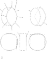
Die nachfolgenden
Die linke Seite von
Die
- 1:1:
- Behältercontainer
- 2:2:
- VerschlusseinrichtungLocking device
- 3:3:
- Deckellid
- 4:4:
- oberer Querschnitt der Verschlusseinrichtungtop cross-section of the locking device
- 5:5:
- unterer Querschnitt der Verschlusseinrichtunglower cross-section of the locking device
- 6:6:
- EckenCorners
- 7:7:
- bogenförmigen Linienarcuate lines
- 8:8th:
- HalteelementRetaining element
- 9:9:
- AufnahmevorrichtungCradle
- 10:10:
- Seiten der VerschlusseinrichtungSides of the locking device
- 11:11:
- eingreifender Teil des Halteelementsengaging part of the retaining element
Claims (13)
- A container (1) having a closure device (2) and a cover (3), wherein
the closure device (2) has an upper cross-section (4) that is substantially of round, triangular, or polygonal shape; and
wherein at least two retaining elements (8, 8') are arranged in the region of the lower cross-section (5) at the closure device (2);
wherein the cover (3) has a reception device (9, 9') for the retaining elements (8, 8') of the closure device (2) that ensure that the cover (3) is retained by the closure device (2); and
wherein the container (1) has a substantially round opening into which the closure device (2) engages in the closed state of the container (1),
characterized in that this upper cross-section (4) merges into a lower non-round cross-section (5) that is defined by n corners (6) and by n arc-shaped lines (7) connecting these corners,
where n is a whole number from 2 to 6;
wherein the corners (6) project, viewed axially, over the substantially round, triangular, or polygonal upper cross-section (4) and the arc-shaped lines (7) are set back, viewed axially, behind the substantially round, triangular, or polygonal upper cross-section (4); - A container in accordance with claim 1, characterized in that
the closure device (2) has two retaining elements (8, 8') that are preferably arranged at oppositely disposed sides (10, 10') of the closure device (2). - A container in accordance with claim 1 or claim 2, characterized in that
the retaining elements (8, 8') are retaining webs; and/or
in that the reception devices (9, 9') are grooves,
wherein it is preferred that the retaining elements (8, 8') are retaining webs and the reception devices (9, 9') are grooves. - A container in accordance with one of the preceding claims,
characterized in that
the number of retaining elements (8, 8') corresponds to the number of corners (6). - A container in accordance with one of the preceding claims,
characterized in that
the upper cross-section (4) is of substantially round shape; and in that the reception device is a peripheral groove. - A container in accordance with one of the preceding claims,
characterized in that
the part (11) of the retaining element (8, 8') engaging into the reception device (9, 9') engages into the reception device (9, 9') over a depth of 0.3 to 1.5 mm and preferably 0.5 to 1 mm in the closed state of the container; and/or
in that the part (11) of the retaining element (8, 8') engaging into the reception device (9, 9') engages into the reception device (9, 9') over 5 to 60% and preferably 20 to 40% of the total peripheral length in the closed state of the container. - A container in accordance with one of the preceding claims,
characterized in that
n is in the range from 3 to 6 and preferably in the range from 3 to 5, particularly preferably n is 4. - A container in accordance with one of the preceding claims,
characterized in that
the closure device (2) is completely arranged in the interior of the cover (3). - A container in accordance with one of the preceding claims,
characterized in that
the closure device (2) comprises a plastic and preferably consists thereof, with the plastic particularly preferably being selected from the group comprising acetal resins, liquid crystal polymers, polyacrylates, polymethacrylates, olefinic and cycloolefinic polymers, polyamides, polyamide elastomers, polyamideimides, polyarylethers containing polyphenyl ethers, polycarbonates, polyimides, polyesters, polyesterpolycarbonates, polyethers, polyoxyethylenes, polysulfones, polystyrene, vinyl polymers or mixtures thereof. - A container in accordance with one of the preceding claims,
characterized in that
the upper cross-section (4) of the closure device and/or the opening of the container is/are circular. - A container in accordance with one of the preceding claims,
characterized in that
the container (1) and/or the cover (3) consist/consists of stainless steel, with it being preferred that both the container (1) and the cover (3) consist of stainless steel. - A container in accordance with one of the preceding claims,
characterized in that
the cover (3) is configured in the form of a tumbler, with this tumbler preferably being double-walled. - A container in accordance with one of the preceding claims,
characterized in that
the container (1) is selected from the group comprising vacuum flasks, insulated tumblers, insulated containers, and storage containers with and without an insulation function
Applications Claiming Priority (2)
| Application Number | Priority Date | Filing Date | Title |
|---|---|---|---|
| DE102017217247.9A DE102017217247A1 (en) | 2017-09-27 | 2017-09-27 | Container with closure device and lid |
| PCT/EP2018/070808 WO2019063164A1 (en) | 2017-09-27 | 2018-07-31 | Container comprising a closure device and cover |
Publications (3)
| Publication Number | Publication Date |
|---|---|
| EP3687916A1 EP3687916A1 (en) | 2020-08-05 |
| EP3687916B1 true EP3687916B1 (en) | 2021-09-22 |
| EP3687916B8 EP3687916B8 (en) | 2021-10-27 |
Family
ID=63350500
Family Applications (1)
| Application Number | Title | Priority Date | Filing Date |
|---|---|---|---|
| EP18759039.3A Active EP3687916B8 (en) | 2017-09-27 | 2018-07-31 | Container comprising a closure device and cover |
Country Status (4)
| Country | Link |
|---|---|
| EP (1) | EP3687916B8 (en) |
| CN (1) | CN111148700B (en) |
| DE (1) | DE102017217247A1 (en) |
| WO (1) | WO2019063164A1 (en) |
Family Cites Families (12)
| Publication number | Priority date | Publication date | Assignee | Title |
|---|---|---|---|---|
| DE567569C (en) * | 1932-03-01 | 1933-09-23 | Wilhelm Herusch | Device for attaching the beaker to vacuum flasks |
| US2765960A (en) | 1953-07-27 | 1956-10-09 | Dev Res Inc | Reusable retentive closure for containers |
| DE8400247U1 (en) * | 1984-01-05 | 1984-04-26 | Rotpunkt Dr. Anso Zimmermann, 6434 Niederaula | JUG, IN PARTICULAR INSULATING JUG |
| DE8408858U1 (en) * | 1984-03-22 | 1984-08-02 | Rotpunkt Dr. Anso Zimmermann, 6434 Niederaula | INSULATING VESSEL, IN PARTICULAR INSULATING JUG, INSULATING BOTTLE OR INSULATING FEEDING TUBE |
| DE3508617C1 (en) | 1985-03-11 | 1986-09-25 | Hartmut 8032 Gräfelfing Nickel | Vacuum jug |
| DE29512058U1 (en) * | 1995-07-26 | 1996-12-05 | Buerkle Felix | Aluminum drink bottle |
| AUPN452495A0 (en) | 1995-07-31 | 1995-08-24 | White, Johanna Kay | A drainage plug assembly |
| CN2297957Y (en) * | 1997-06-23 | 1998-11-25 | 孙凤志 | Sanitation thermos bottle stopper |
| US7455191B2 (en) * | 2004-12-14 | 2008-11-25 | Sun Coast Merchandise Corporation | Triangular mug and advertising means |
| CL2007002373A1 (en) * | 2006-08-17 | 2008-01-11 | Zork Pty Ltd | A bottle closure for bottles containing high-pressure liquids, with the closure having a first part and a second part, where the first part has a portion adapted to receive a portion of an upper section of a bottleneck, and a second part that fits over the first part. |
| CN103156513A (en) * | 2013-02-07 | 2013-06-19 | 符名介 | Leakage-proof electric thermos mug |
| DE102013222912B4 (en) * | 2013-11-11 | 2021-01-21 | Wmf Group Gmbh | Containers, in particular storage containers, with lids |
-
2017
- 2017-09-27 DE DE102017217247.9A patent/DE102017217247A1/en not_active Withdrawn
-
2018
- 2018-07-31 CN CN201880062528.8A patent/CN111148700B/en active Active
- 2018-07-31 EP EP18759039.3A patent/EP3687916B8/en active Active
- 2018-07-31 WO PCT/EP2018/070808 patent/WO2019063164A1/en unknown
Also Published As
| Publication number | Publication date |
|---|---|
| WO2019063164A1 (en) | 2019-04-04 |
| CN111148700B (en) | 2021-09-17 |
| EP3687916B8 (en) | 2021-10-27 |
| DE102017217247A1 (en) | 2019-04-11 |
| EP3687916A1 (en) | 2020-08-05 |
| CN111148700A (en) | 2020-05-12 |
Similar Documents
| Publication | Publication Date | Title |
|---|---|---|
| DE3226910A1 (en) | PROTECTIVE CLASP | |
| DE3640040C2 (en) | ||
| EP3956238B1 (en) | Container closure | |
| EP0383131A1 (en) | Collapsible container for liquid substances | |
| EP2794410B1 (en) | Stack canister | |
| EP3687916B1 (en) | Container comprising a closure device and cover | |
| WO1998035879A1 (en) | Container of liquid transport and storage | |
| DE1924824C3 (en) | Pull-out pouring cap | |
| EP2646337B1 (en) | Drinking container for beverages | |
| DE102010029259A1 (en) | Closure device for a container for dispensing a substance | |
| WO2011006274A1 (en) | Closure for a container | |
| WO2009089856A1 (en) | Container having pivotable handle and lid lock | |
| DE3347713C2 (en) | Closure arrangement with rotary knob and stopper for a vessel | |
| EP4161845A1 (en) | Container closure | |
| WO1993008093A1 (en) | Plastic container | |
| EP2335826B1 (en) | Identifiable container | |
| DE8603165U1 (en) | Containers for the transport of dangerous liquids | |
| DE1486225A1 (en) | Thin-walled vessel, deep-drawn from thermoplastic plastic film, with a closure lid, for example ice cream cups, Schuettelbecher or the like. | |
| DE102015113761B3 (en) | Arrangement for receiving and method for the portioned provision of a total volume of a liquid to be drunk | |
| DE602004010508T2 (en) | Cones for beverage containers | |
| DE2806759C3 (en) | Bunghole closure for a pressure vessel | |
| EP2598404B1 (en) | Plastic container | |
| EP1790582B1 (en) | Tamper evident closure | |
| WO2014170140A1 (en) | Container for receiving beverages containing carbon dioxide | |
| WO2013182283A1 (en) | Drinking cup cover with a drinking aperture |
Legal Events
| Date | Code | Title | Description |
|---|---|---|---|
| STAA | Information on the status of an ep patent application or granted ep patent |
Free format text: STATUS: UNKNOWN |
|
| STAA | Information on the status of an ep patent application or granted ep patent |
Free format text: STATUS: THE INTERNATIONAL PUBLICATION HAS BEEN MADE |
|
| PUAI | Public reference made under article 153(3) epc to a published international application that has entered the european phase |
Free format text: ORIGINAL CODE: 0009012 |
|
| STAA | Information on the status of an ep patent application or granted ep patent |
Free format text: STATUS: REQUEST FOR EXAMINATION WAS MADE |
|
| 17P | Request for examination filed |
Effective date: 20200207 |
|
| AK | Designated contracting states |
Kind code of ref document: A1 Designated state(s): AL AT BE BG CH CY CZ DE DK EE ES FI FR GB GR HR HU IE IS IT LI LT LU LV MC MK MT NL NO PL PT RO RS SE SI SK SM TR |
|
| AX | Request for extension of the european patent |
Extension state: BA ME |
|
| DAV | Request for validation of the european patent (deleted) | ||
| DAX | Request for extension of the european patent (deleted) | ||
| GRAP | Despatch of communication of intention to grant a patent |
Free format text: ORIGINAL CODE: EPIDOSNIGR1 |
|
| STAA | Information on the status of an ep patent application or granted ep patent |
Free format text: STATUS: GRANT OF PATENT IS INTENDED |
|
| INTG | Intention to grant announced |
Effective date: 20210520 |
|
| GRAS | Grant fee paid |
Free format text: ORIGINAL CODE: EPIDOSNIGR3 |
|
| GRAA | (expected) grant |
Free format text: ORIGINAL CODE: 0009210 |
|
| STAA | Information on the status of an ep patent application or granted ep patent |
Free format text: STATUS: THE PATENT HAS BEEN GRANTED |
|
| AK | Designated contracting states |
Kind code of ref document: B1 Designated state(s): AL AT BE BG CH CY CZ DE DK EE ES FI FR GB GR HR HU IE IS IT LI LT LU LV MC MK MT NL NO PL PT RO RS SE SI SK SM TR |
|
| REG | Reference to a national code |
Ref country code: GB Ref legal event code: FG4D Free format text: NOT ENGLISH |
|
| REG | Reference to a national code |
Ref country code: DE Ref legal event code: R081 Ref document number: 502018007189 Country of ref document: DE Owner name: WMF GMBH, DE Free format text: FORMER OWNER: WMF GROUP GMBH, 73312 GEISLINGEN, DE |
|
| REG | Reference to a national code |
Ref country code: IE Ref legal event code: FG4D Free format text: LANGUAGE OF EP DOCUMENT: GERMAN |
|
| REG | Reference to a national code |
Ref country code: DE Ref legal event code: R096 Ref document number: 502018007189 Country of ref document: DE |
|
| REG | Reference to a national code |
Ref country code: CH Ref legal event code: PK Free format text: BERICHTIGUNG B8 Ref country code: CH Ref legal event code: EP Ref country code: AT Ref legal event code: REF Ref document number: 1432163 Country of ref document: AT Kind code of ref document: T Effective date: 20211015 |
|
| RAP4 | Party data changed (patent owner data changed or rights of a patent transferred) |
Owner name: WMF GMBH |
|
| REG | Reference to a national code |
Ref country code: LT Ref legal event code: MG9D |
|
| REG | Reference to a national code |
Ref country code: NL Ref legal event code: MP Effective date: 20210922 |
|
| PG25 | Lapsed in a contracting state [announced via postgrant information from national office to epo] |
Ref country code: BG Free format text: LAPSE BECAUSE OF FAILURE TO SUBMIT A TRANSLATION OF THE DESCRIPTION OR TO PAY THE FEE WITHIN THE PRESCRIBED TIME-LIMIT Effective date: 20211222 Ref country code: LT Free format text: LAPSE BECAUSE OF FAILURE TO SUBMIT A TRANSLATION OF THE DESCRIPTION OR TO PAY THE FEE WITHIN THE PRESCRIBED TIME-LIMIT Effective date: 20210922 Ref country code: NO Free format text: LAPSE BECAUSE OF FAILURE TO SUBMIT A TRANSLATION OF THE DESCRIPTION OR TO PAY THE FEE WITHIN THE PRESCRIBED TIME-LIMIT Effective date: 20211222 Ref country code: SE Free format text: LAPSE BECAUSE OF FAILURE TO SUBMIT A TRANSLATION OF THE DESCRIPTION OR TO PAY THE FEE WITHIN THE PRESCRIBED TIME-LIMIT Effective date: 20210922 Ref country code: RS Free format text: LAPSE BECAUSE OF FAILURE TO SUBMIT A TRANSLATION OF THE DESCRIPTION OR TO PAY THE FEE WITHIN THE PRESCRIBED TIME-LIMIT Effective date: 20210922 Ref country code: FI Free format text: LAPSE BECAUSE OF FAILURE TO SUBMIT A TRANSLATION OF THE DESCRIPTION OR TO PAY THE FEE WITHIN THE PRESCRIBED TIME-LIMIT Effective date: 20210922 Ref country code: HR Free format text: LAPSE BECAUSE OF FAILURE TO SUBMIT A TRANSLATION OF THE DESCRIPTION OR TO PAY THE FEE WITHIN THE PRESCRIBED TIME-LIMIT Effective date: 20210922 |
|
| PG25 | Lapsed in a contracting state [announced via postgrant information from national office to epo] |
Ref country code: LV Free format text: LAPSE BECAUSE OF FAILURE TO SUBMIT A TRANSLATION OF THE DESCRIPTION OR TO PAY THE FEE WITHIN THE PRESCRIBED TIME-LIMIT Effective date: 20210922 Ref country code: GR Free format text: LAPSE BECAUSE OF FAILURE TO SUBMIT A TRANSLATION OF THE DESCRIPTION OR TO PAY THE FEE WITHIN THE PRESCRIBED TIME-LIMIT Effective date: 20211223 |
|
| PG25 | Lapsed in a contracting state [announced via postgrant information from national office to epo] |
Ref country code: IS Free format text: LAPSE BECAUSE OF FAILURE TO SUBMIT A TRANSLATION OF THE DESCRIPTION OR TO PAY THE FEE WITHIN THE PRESCRIBED TIME-LIMIT Effective date: 20220122 Ref country code: SK Free format text: LAPSE BECAUSE OF FAILURE TO SUBMIT A TRANSLATION OF THE DESCRIPTION OR TO PAY THE FEE WITHIN THE PRESCRIBED TIME-LIMIT Effective date: 20210922 Ref country code: RO Free format text: LAPSE BECAUSE OF FAILURE TO SUBMIT A TRANSLATION OF THE DESCRIPTION OR TO PAY THE FEE WITHIN THE PRESCRIBED TIME-LIMIT Effective date: 20210922 Ref country code: PT Free format text: LAPSE BECAUSE OF FAILURE TO SUBMIT A TRANSLATION OF THE DESCRIPTION OR TO PAY THE FEE WITHIN THE PRESCRIBED TIME-LIMIT Effective date: 20220124 Ref country code: PL Free format text: LAPSE BECAUSE OF FAILURE TO SUBMIT A TRANSLATION OF THE DESCRIPTION OR TO PAY THE FEE WITHIN THE PRESCRIBED TIME-LIMIT Effective date: 20210922 Ref country code: NL Free format text: LAPSE BECAUSE OF FAILURE TO SUBMIT A TRANSLATION OF THE DESCRIPTION OR TO PAY THE FEE WITHIN THE PRESCRIBED TIME-LIMIT Effective date: 20210922 Ref country code: ES Free format text: LAPSE BECAUSE OF FAILURE TO SUBMIT A TRANSLATION OF THE DESCRIPTION OR TO PAY THE FEE WITHIN THE PRESCRIBED TIME-LIMIT Effective date: 20210922 Ref country code: EE Free format text: LAPSE BECAUSE OF FAILURE TO SUBMIT A TRANSLATION OF THE DESCRIPTION OR TO PAY THE FEE WITHIN THE PRESCRIBED TIME-LIMIT Effective date: 20210922 Ref country code: CZ Free format text: LAPSE BECAUSE OF FAILURE TO SUBMIT A TRANSLATION OF THE DESCRIPTION OR TO PAY THE FEE WITHIN THE PRESCRIBED TIME-LIMIT Effective date: 20210922 Ref country code: AL Free format text: LAPSE BECAUSE OF FAILURE TO SUBMIT A TRANSLATION OF THE DESCRIPTION OR TO PAY THE FEE WITHIN THE PRESCRIBED TIME-LIMIT Effective date: 20210922 |
|
| REG | Reference to a national code |
Ref country code: DE Ref legal event code: R097 Ref document number: 502018007189 Country of ref document: DE |
|
| PG25 | Lapsed in a contracting state [announced via postgrant information from national office to epo] |
Ref country code: DK Free format text: LAPSE BECAUSE OF FAILURE TO SUBMIT A TRANSLATION OF THE DESCRIPTION OR TO PAY THE FEE WITHIN THE PRESCRIBED TIME-LIMIT Effective date: 20210922 |
|
| PLBE | No opposition filed within time limit |
Free format text: ORIGINAL CODE: 0009261 |
|
| STAA | Information on the status of an ep patent application or granted ep patent |
Free format text: STATUS: NO OPPOSITION FILED WITHIN TIME LIMIT |
|
| 26N | No opposition filed |
Effective date: 20220623 |
|
| PG25 | Lapsed in a contracting state [announced via postgrant information from national office to epo] |
Ref country code: SI Free format text: LAPSE BECAUSE OF FAILURE TO SUBMIT A TRANSLATION OF THE DESCRIPTION OR TO PAY THE FEE WITHIN THE PRESCRIBED TIME-LIMIT Effective date: 20210922 |
|
| PG25 | Lapsed in a contracting state [announced via postgrant information from national office to epo] |
Ref country code: IT Free format text: LAPSE BECAUSE OF FAILURE TO SUBMIT A TRANSLATION OF THE DESCRIPTION OR TO PAY THE FEE WITHIN THE PRESCRIBED TIME-LIMIT Effective date: 20210922 |
|
| PG25 | Lapsed in a contracting state [announced via postgrant information from national office to epo] |
Ref country code: MC Free format text: LAPSE BECAUSE OF FAILURE TO SUBMIT A TRANSLATION OF THE DESCRIPTION OR TO PAY THE FEE WITHIN THE PRESCRIBED TIME-LIMIT Effective date: 20210922 |
|
| GBPC | Gb: european patent ceased through non-payment of renewal fee |
Effective date: 20220731 |
|
| REG | Reference to a national code |
Ref country code: BE Ref legal event code: MM Effective date: 20220731 |
|
| PG25 | Lapsed in a contracting state [announced via postgrant information from national office to epo] |
Ref country code: LU Free format text: LAPSE BECAUSE OF NON-PAYMENT OF DUE FEES Effective date: 20220731 Ref country code: FR Free format text: LAPSE BECAUSE OF NON-PAYMENT OF DUE FEES Effective date: 20220731 |
|
| PG25 | Lapsed in a contracting state [announced via postgrant information from national office to epo] |
Ref country code: GB Free format text: LAPSE BECAUSE OF NON-PAYMENT OF DUE FEES Effective date: 20220731 Ref country code: BE Free format text: LAPSE BECAUSE OF NON-PAYMENT OF DUE FEES Effective date: 20220731 |
|
| P01 | Opt-out of the competence of the unified patent court (upc) registered |
Effective date: 20230525 |
|
| PG25 | Lapsed in a contracting state [announced via postgrant information from national office to epo] |
Ref country code: IE Free format text: LAPSE BECAUSE OF NON-PAYMENT OF DUE FEES Effective date: 20220731 |
|
| PGFP | Annual fee paid to national office [announced via postgrant information from national office to epo] |
Ref country code: CH Payment date: 20230801 Year of fee payment: 6 Ref country code: AT Payment date: 20230621 Year of fee payment: 6 |
|
| PGFP | Annual fee paid to national office [announced via postgrant information from national office to epo] |
Ref country code: DE Payment date: 20230712 Year of fee payment: 6 |
|
| PG25 | Lapsed in a contracting state [announced via postgrant information from national office to epo] |
Ref country code: SM Free format text: LAPSE BECAUSE OF FAILURE TO SUBMIT A TRANSLATION OF THE DESCRIPTION OR TO PAY THE FEE WITHIN THE PRESCRIBED TIME-LIMIT Effective date: 20210922 Ref country code: MK Free format text: LAPSE BECAUSE OF FAILURE TO SUBMIT A TRANSLATION OF THE DESCRIPTION OR TO PAY THE FEE WITHIN THE PRESCRIBED TIME-LIMIT Effective date: 20210922 Ref country code: CY Free format text: LAPSE BECAUSE OF FAILURE TO SUBMIT A TRANSLATION OF THE DESCRIPTION OR TO PAY THE FEE WITHIN THE PRESCRIBED TIME-LIMIT Effective date: 20210922 |