EP3687285B1 - Method and system for tracking companion animals and alerting animal owners of lost companion animals - Google Patents
Method and system for tracking companion animals and alerting animal owners of lost companion animals Download PDFInfo
- Publication number
- EP3687285B1 EP3687285B1 EP18786174.5A EP18786174A EP3687285B1 EP 3687285 B1 EP3687285 B1 EP 3687285B1 EP 18786174 A EP18786174 A EP 18786174A EP 3687285 B1 EP3687285 B1 EP 3687285B1
- Authority
- EP
- European Patent Office
- Prior art keywords
- tag
- server
- nfc
- animal
- electronic tag
- Prior art date
- Legal status (The legal status is an assumption and is not a legal conclusion. Google has not performed a legal analysis and makes no representation as to the accuracy of the status listed.)
- Active
Links
- 241001465754 Metazoa Species 0.000 title claims description 473
- 238000000034 method Methods 0.000 title claims description 81
- 238000004891 communication Methods 0.000 claims description 175
- 230000006854 communication Effects 0.000 claims description 170
- 238000004519 manufacturing process Methods 0.000 claims description 114
- 230000008878 coupling Effects 0.000 claims description 17
- 238000010168 coupling process Methods 0.000 claims description 17
- 238000005859 coupling reaction Methods 0.000 claims description 17
- 230000001413 cellular effect Effects 0.000 claims description 12
- 230000008859 change Effects 0.000 claims description 11
- 238000012544 monitoring process Methods 0.000 claims description 5
- 101100148933 Caenorhabditis elegans sdhb-1 gene Proteins 0.000 description 32
- 229910000679 solder Inorganic materials 0.000 description 22
- 239000000758 substrate Substances 0.000 description 19
- 238000011282 treatment Methods 0.000 description 17
- 230000008569 process Effects 0.000 description 15
- 239000000126 substance Substances 0.000 description 15
- 230000009471 action Effects 0.000 description 14
- 238000003860 storage Methods 0.000 description 13
- 229940079593 drug Drugs 0.000 description 12
- 239000003814 drug Substances 0.000 description 12
- 230000006870 function Effects 0.000 description 11
- 239000010985 leather Substances 0.000 description 11
- 241000283690 Bos taurus Species 0.000 description 10
- 239000004033 plastic Substances 0.000 description 10
- 230000004044 response Effects 0.000 description 10
- 230000003287 optical effect Effects 0.000 description 9
- 230000036541 health Effects 0.000 description 8
- 239000000463 material Substances 0.000 description 8
- 230000008520 organization Effects 0.000 description 8
- 241000282887 Suidae Species 0.000 description 7
- 238000013480 data collection Methods 0.000 description 7
- 230000003247 decreasing effect Effects 0.000 description 7
- 244000144972 livestock Species 0.000 description 7
- 238000012545 processing Methods 0.000 description 7
- 229960005486 vaccine Drugs 0.000 description 7
- 241000282472 Canis lupus familiaris Species 0.000 description 6
- 241000283086 Equidae Species 0.000 description 6
- 238000010586 diagram Methods 0.000 description 6
- 238000005516 engineering process Methods 0.000 description 6
- 239000004744 fabric Substances 0.000 description 6
- 239000000047 product Substances 0.000 description 6
- 230000000153 supplemental effect Effects 0.000 description 6
- 239000003826 tablet Substances 0.000 description 6
- 230000009977 dual effect Effects 0.000 description 5
- 230000005055 memory storage Effects 0.000 description 5
- 230000010076 replication Effects 0.000 description 5
- 241000272517 Anseriformes Species 0.000 description 4
- 241000282326 Felis catus Species 0.000 description 4
- 241000287828 Gallus gallus Species 0.000 description 4
- 239000013543 active substance Substances 0.000 description 4
- 230000008901 benefit Effects 0.000 description 4
- 230000033228 biological regulation Effects 0.000 description 4
- 235000013330 chicken meat Nutrition 0.000 description 4
- 239000011521 glass Substances 0.000 description 4
- 230000007246 mechanism Effects 0.000 description 4
- 230000006855 networking Effects 0.000 description 4
- 238000002255 vaccination Methods 0.000 description 4
- 241001494479 Pecora Species 0.000 description 3
- 241000286209 Phasianidae Species 0.000 description 3
- 238000010171 animal model Methods 0.000 description 3
- 239000011324 bead Substances 0.000 description 3
- 239000000919 ceramic Substances 0.000 description 3
- 230000001419 dependent effect Effects 0.000 description 3
- 239000003989 dielectric material Substances 0.000 description 3
- 239000007943 implant Substances 0.000 description 3
- 230000005291 magnetic effect Effects 0.000 description 3
- 230000000590 parasiticidal effect Effects 0.000 description 3
- 239000002297 parasiticide Substances 0.000 description 3
- 238000012552 review Methods 0.000 description 3
- 230000000007 visual effect Effects 0.000 description 3
- KJLPSBMDOIVXSN-UHFFFAOYSA-N 4-[4-[2-[4-(3,4-dicarboxyphenoxy)phenyl]propan-2-yl]phenoxy]phthalic acid Chemical compound C=1C=C(OC=2C=C(C(C(O)=O)=CC=2)C(O)=O)C=CC=1C(C)(C)C(C=C1)=CC=C1OC1=CC=C(C(O)=O)C(C(O)=O)=C1 KJLPSBMDOIVXSN-UHFFFAOYSA-N 0.000 description 2
- 241000271566 Aves Species 0.000 description 2
- 241000282832 Camelidae Species 0.000 description 2
- 241000282836 Camelus dromedarius Species 0.000 description 2
- 241000282994 Cervidae Species 0.000 description 2
- 238000007792 addition Methods 0.000 description 2
- 230000002141 anti-parasite Effects 0.000 description 2
- 239000003096 antiparasitic agent Substances 0.000 description 2
- 238000013475 authorization Methods 0.000 description 2
- 230000007175 bidirectional communication Effects 0.000 description 2
- 244000309466 calf Species 0.000 description 2
- 238000004140 cleaning Methods 0.000 description 2
- 230000000295 complement effect Effects 0.000 description 2
- 239000002131 composite material Substances 0.000 description 2
- 230000035558 fertility Effects 0.000 description 2
- 239000000835 fiber Substances 0.000 description 2
- 230000000737 periodic effect Effects 0.000 description 2
- 230000002093 peripheral effect Effects 0.000 description 2
- 150000003839 salts Chemical class 0.000 description 2
- 238000013515 script Methods 0.000 description 2
- 239000004065 semiconductor Substances 0.000 description 2
- 241000894007 species Species 0.000 description 2
- 239000013589 supplement Substances 0.000 description 2
- 230000001360 synchronised effect Effects 0.000 description 2
- 238000012546 transfer Methods 0.000 description 2
- 235000013343 vitamin Nutrition 0.000 description 2
- 239000011782 vitamin Substances 0.000 description 2
- 229940088594 vitamin Drugs 0.000 description 2
- 229930003231 vitamin Natural products 0.000 description 2
- VBRBNWWNRIMAII-WYMLVPIESA-N 3-[(e)-5-(4-ethylphenoxy)-3-methylpent-3-enyl]-2,2-dimethyloxirane Chemical compound C1=CC(CC)=CC=C1OC\C=C(/C)CCC1C(C)(C)O1 VBRBNWWNRIMAII-WYMLVPIESA-N 0.000 description 1
- 241000251468 Actinopterygii Species 0.000 description 1
- 241000283725 Bos Species 0.000 description 1
- 101100079986 Caenorhabditis elegans nrfl-1 gene Proteins 0.000 description 1
- 241000283707 Capra Species 0.000 description 1
- 241000282693 Cercopithecidae Species 0.000 description 1
- 241000251730 Chondrichthyes Species 0.000 description 1
- 241001125840 Coryphaenidae Species 0.000 description 1
- 235000017274 Diospyros sandwicensis Nutrition 0.000 description 1
- 241000282327 Felis silvestris Species 0.000 description 1
- 206010020751 Hypersensitivity Diseases 0.000 description 1
- 241000282838 Lama Species 0.000 description 1
- 241000699666 Mus <mouse, genus> Species 0.000 description 1
- 241000699670 Mus sp. Species 0.000 description 1
- 241000282339 Mustela Species 0.000 description 1
- 241001025261 Neoraja caerulea Species 0.000 description 1
- 241000283973 Oryctolagus cuniculus Species 0.000 description 1
- 241000282320 Panthera leo Species 0.000 description 1
- 241000282335 Procyon Species 0.000 description 1
- 206010037742 Rabies Diseases 0.000 description 1
- 241000700159 Rattus Species 0.000 description 1
- 241000271567 Struthioniformes Species 0.000 description 1
- RTAQQCXQSZGOHL-UHFFFAOYSA-N Titanium Chemical compound [Ti] RTAQQCXQSZGOHL-UHFFFAOYSA-N 0.000 description 1
- 241000282485 Vulpes vulpes Species 0.000 description 1
- 230000007815 allergy Effects 0.000 description 1
- 230000004075 alteration Effects 0.000 description 1
- 239000003242 anti bacterial agent Substances 0.000 description 1
- 229940088710 antibiotic agent Drugs 0.000 description 1
- 230000006399 behavior Effects 0.000 description 1
- 229920000249 biocompatible polymer Polymers 0.000 description 1
- 238000009395 breeding Methods 0.000 description 1
- 230000001488 breeding effect Effects 0.000 description 1
- 230000015556 catabolic process Effects 0.000 description 1
- 150000001875 compounds Chemical class 0.000 description 1
- 238000004590 computer program Methods 0.000 description 1
- 230000002596 correlated effect Effects 0.000 description 1
- 230000009849 deactivation Effects 0.000 description 1
- 230000007547 defect Effects 0.000 description 1
- 238000001514 detection method Methods 0.000 description 1
- 238000009826 distribution Methods 0.000 description 1
- 230000000694 effects Effects 0.000 description 1
- 238000004100 electronic packaging Methods 0.000 description 1
- 239000003822 epoxy resin Substances 0.000 description 1
- 239000000284 extract Substances 0.000 description 1
- 230000005294 ferromagnetic effect Effects 0.000 description 1
- 239000000945 filler Substances 0.000 description 1
- 230000037406 food intake Effects 0.000 description 1
- 239000003365 glass fiber Substances 0.000 description 1
- 239000003292 glue Substances 0.000 description 1
- 244000144980 herd Species 0.000 description 1
- 239000005556 hormone Substances 0.000 description 1
- 229940088597 hormone Drugs 0.000 description 1
- 238000001746 injection moulding Methods 0.000 description 1
- 230000009027 insemination Effects 0.000 description 1
- 239000004973 liquid crystal related substance Substances 0.000 description 1
- 230000004807 localization Effects 0.000 description 1
- 230000013011 mating Effects 0.000 description 1
- 239000011159 matrix material Substances 0.000 description 1
- 238000002483 medication Methods 0.000 description 1
- 229910044991 metal oxide Inorganic materials 0.000 description 1
- 150000004706 metal oxides Chemical class 0.000 description 1
- 239000012811 non-conductive material Substances 0.000 description 1
- 235000015097 nutrients Nutrition 0.000 description 1
- 235000016709 nutrition Nutrition 0.000 description 1
- 230000035764 nutrition Effects 0.000 description 1
- 210000000056 organ Anatomy 0.000 description 1
- 229920000647 polyepoxide Polymers 0.000 description 1
- 230000035935 pregnancy Effects 0.000 description 1
- 238000007639 printing Methods 0.000 description 1
- 230000001681 protective effect Effects 0.000 description 1
- 230000002787 reinforcement Effects 0.000 description 1
- 230000001850 reproductive effect Effects 0.000 description 1
- 229920005989 resin Polymers 0.000 description 1
- 239000011347 resin Substances 0.000 description 1
- 239000005060 rubber Substances 0.000 description 1
- 238000000926 separation method Methods 0.000 description 1
- 239000000243 solution Substances 0.000 description 1
- 238000001228 spectrum Methods 0.000 description 1
- 238000006467 substitution reaction Methods 0.000 description 1
- 238000012549 training Methods 0.000 description 1
- 238000005303 weighing Methods 0.000 description 1
Images


Classifications
-
- A—HUMAN NECESSITIES
- A01—AGRICULTURE; FORESTRY; ANIMAL HUSBANDRY; HUNTING; TRAPPING; FISHING
- A01K—ANIMAL HUSBANDRY; CARE OF BIRDS, FISHES, INSECTS; FISHING; REARING OR BREEDING ANIMALS, NOT OTHERWISE PROVIDED FOR; NEW BREEDS OF ANIMALS
- A01K11/00—Marking of animals
- A01K11/006—Automatic identification systems for animals, e.g. electronic devices, transponders for animals
- A01K11/008—Automatic identification systems for animals, e.g. electronic devices, transponders for animals incorporating GPS
-
- A—HUMAN NECESSITIES
- A01—AGRICULTURE; FORESTRY; ANIMAL HUSBANDRY; HUNTING; TRAPPING; FISHING
- A01K—ANIMAL HUSBANDRY; CARE OF BIRDS, FISHES, INSECTS; FISHING; REARING OR BREEDING ANIMALS, NOT OTHERWISE PROVIDED FOR; NEW BREEDS OF ANIMALS
- A01K11/00—Marking of animals
- A01K11/006—Automatic identification systems for animals, e.g. electronic devices, transponders for animals
- A01K11/007—Boluses
-
- A—HUMAN NECESSITIES
- A01—AGRICULTURE; FORESTRY; ANIMAL HUSBANDRY; HUNTING; TRAPPING; FISHING
- A01K—ANIMAL HUSBANDRY; CARE OF BIRDS, FISHES, INSECTS; FISHING; REARING OR BREEDING ANIMALS, NOT OTHERWISE PROVIDED FOR; NEW BREEDS OF ANIMALS
- A01K15/00—Devices for taming animals, e.g. nose-rings or hobbles; Devices for overturning animals in general; Training or exercising equipment; Covering boxes
- A01K15/02—Training or exercising equipment, e.g. mazes or labyrinths for animals ; Electric shock devices ; Toys specially adapted for animals
- A01K15/021—Electronic training devices specially adapted for dogs or cats
- A01K15/023—Anti-evasion devices
-
- A—HUMAN NECESSITIES
- A01—AGRICULTURE; FORESTRY; ANIMAL HUSBANDRY; HUNTING; TRAPPING; FISHING
- A01K—ANIMAL HUSBANDRY; CARE OF BIRDS, FISHES, INSECTS; FISHING; REARING OR BREEDING ANIMALS, NOT OTHERWISE PROVIDED FOR; NEW BREEDS OF ANIMALS
- A01K29/00—Other apparatus for animal husbandry
- A01K29/005—Monitoring or measuring activity, e.g. detecting heat or mating
-
- H04B5/77—
-
- H—ELECTRICITY
- H04—ELECTRIC COMMUNICATION TECHNIQUE
- H04W—WIRELESS COMMUNICATION NETWORKS
- H04W4/00—Services specially adapted for wireless communication networks; Facilities therefor
- H04W4/02—Services making use of location information
- H04W4/021—Services related to particular areas, e.g. point of interest [POI] services, venue services or geofences
Description
- Conventional computer systems and electronic/smart tags that are attached to animals have been developed for tracking animals, such as herds of animals that may be part of the livestock/cattle industry. Other electronic/smart tags have been developed for tracking medical records for companion animals, such as dogs and cats.
- While the electronic/smart tags for companion animals may be helpful when they are located by other people when a companion animal is lost, such tags do not provide information to the owner on how to locate the companion animal when the companion animal is lost. Further, conventional tags usually do not allow people to easily collect/scan the information from the electronic/smart tag. Often, only a veterinarian will have the necessary equipment such as a specialized tag reader device that is needed to scan information from the electronic/smart tag which is attached to the companion animal.
- Therefore, what is needed in the art is a system and method for tracking animals with electronic/smart tags in which a portable computing device (PCD), such as a mobile telephone, can scan the information from the electronic/smart tag. Another need exists in the art for an electronic/smart tag which may assist the owner using a PCD such as a mobile telephone to determine the location of a lost companion animal.
-
AU 2012/268831 A1 -
WO 2016/189524 A1 describes a system and method for monitoring livestock, the system including a remote server storing data, the remote server including a processing unit for processing stored data and a non-volatile memory; at least one simple data collection device for mounting on an animal to be monitored, the data collection device including a sensor sensing physical parameters of the animal on which it is mounted, a simple data collection device processor with a non-volatile memory, and a transmitter for transmitting data collected by the sensor; at least one central data collection device including a mobile hub for mounting on an animal to be monitored, the central data collection device including: a central data collection device processor with a non- volatile memory; a receiver for receiving data transmitted by the simple data collection devices; a transceiver for communication with the remote server over a communication system; an energy source; the remote server being configured to analyze collected physical parameters and determine therefrom physical condition or behavior of the animal; and a network for two-way communication between the remote server and a remote electronic communication device and configured to provide real time information and warning alarms to the remote electronic communication device. -
US 2013/0157628 A1 describes an electronic fence system capable of guiding animals under training to return to a predetermined restricted area. The fence system may utilize either a plurality of loops to determine direction of travel for a receiver unit or, alternatively, a GPS system. For embodiments utilizing the GPS system, electronic fences are defined in relation to GPS location information. A lock-down mode is used to contain an animal to a very constricted area when a control command is received to initialize the lock down mode or upon a specified condition. Specified conditions include the animal approaching or entering a specified area or, alternatively, a threshold level of charge being reached for a battery that provides power for the receiver unit. A smart phone is communicatively coupled to a controller or interface device which, in turn, is communicatively coupled to a trainer/receiver. -
US 2013/340305 A1 discloses a networked cattle tracking system tracking cattle using a base station, smart tags for cattle, and a mobile device. - Particular and preferred embodiments are set out in the claims. In a first aspect, the present invention is a computer-implemented method for tracking a companion animal (65) and alerting an owner of the companion animal when the companion animal is lost, the method comprising:
- a server (35) generating (1409) a web page (1304) associated with a near-field-communication (NFC) portion of an electronic tag (45), the electronic tag being coupled to the companion animal;
- the server generating (1415) a geo-fence (1306) associated with the electronic tag;
- the server monitoring (1418) the geo-fence to determine if the electronic tag has exited the geo-fence;
- the server sending (1424) a message to the web page if the electronic tag has exited the geo-fence;
- the server sending an alert (1427) to a portable computing device (100) if the electronic tag has exited the geo-fence;
- the server sending (1430) a command to the electronic tag to change from a first rate to a second, faster rate for a device identifier reporting rate if the electronic tag has exited the geo-fence; and
- the server sending a command to the electronic tag to report its present battery level status to a communications network.
- In a further aspect, the present invention is a computer system for tracking a companion animal (65) and alerting an owner of the companion animal when the companion animal is lost, the computer system comprising:
a server (35) generating a web page associated with a near-field-communication (NFC) portion of an electronic tag (45), the electronic tag being coupled to the companion animal; the server adapted for generating a geo-fence associated with the electronic tag; the server adapted for monitoring the geo-fence to determine if the electronic tag has exited the geo-fence; the server adapted for sending a message to the web page if the electronic tag has exited the geo-fence; the server adapted for sending an alert to a portable computing device (100) if the electronic tag has exited the geo-fence; the server adapted for sending a command to the electronic tag to change from a first rate to a second, faster rate for a device identifier reporting rate wherein the device identifier is transmitted to the server by the electronic tag, if the electronic tag has exited the geo-fence; the server adapted for sending a command to the electronic tag to report its present battery level status to a communications network, the electronic tag further comprising a low power wide area (LPWA) portion. - Described herein is a computer system and method for tracking a companion animal and alerting an owner of the companion animal when the companion animal is lost may include a server generating a web page associated with a near-field-communication (NFC) portion of an electronic tag. The electronic tag may be coupled to the companion animal with a mechanical device. The server may generate a geo-fence that is associated with the electronic tag and the server may monitor the geo-fence to determine if the electronic tag has exited the geo-fence.
- The server may send a message to the web page if the electronic tag has exited the geo-fence. The server may then send an alert to a portable computing device if the electronic tag has exited the geo-fence. The server may send a command to the electronic tag to change from a first rate to a second rate for a NFC-tag identifier ("device id" or "device identifier") reporting rate. The server may also send a command to the electronic tag to report its present battery level status to a communications network.
- The electronic tag may comprise a global positioning system (GPS) portion in addition to a low power wide area (LPWA) portion. The NFC portion of the electronic tag is powered by a scanning of the electronic tag while the GPS and LPWA portions may be powered by a battery that is part of the tag.
- For the GPS embodiment of the electronic tag, the GPS portion may transmit the tag geo-coordinates to a communications network after the companion animal has exited the geo-fence. The LPWA portion of the electronic tag for all embodiments may send the device identifier to one or more cellular network towers for triangulation location techniques associated with the towers.
- The server may determine if the NFC portion of the electronic tag has been scanned by a portable computing device. The server may send an alert to the portable computing device if the NFC portion of the electronic tag has been scanned by a device. The portable computing device may comprise at least one of a cellular telephone, a smartphone, a portable digital assistant (PDA), a portable game console, a navigation device, and a tablet computer.
- In the drawings, like reference numerals refer to like parts throughout the various views unless otherwise indicated. For reference numerals with letter character designations such as "102A" or "102B", the letter character designations may differentiate two like parts or elements present in the same figure. Letter character designations for reference numerals may be omitted when it is intended that a reference numeral to encompass all parts having the same reference numeral in all figures.
-
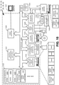
FIG. 1A illustrates a system for tracking a plurality of NFC-enabled animals with a portable computing device according to one exemplary embodiment of the invention. -
FIG. 1B illustrates exemplary NFC-tag data which may be stored within each of the NFC-tags of the system illustrated inFIG. 1A . -
FIG. 1C illustrates exemplary data which may be stored on a domain name service (DNS) server and this figure also illustrates a failure/redundancy plan for each NFC-tag identification server of the system illustrated inFIG. 1A . -
FIG. 1D illustrates respective exemplary geographic locations for each NFC-tag identification server that are illustrated in the system ofFIG. 1A according to one exemplary embodiment of the invention. -
FIG. 1E illustrates how the electronic records maintained by the system ofFIG. 1A may be accessed off-line in addition to how social graphs may be created to enable access and sharing of electronic records within the system. -
FIG. 1F illustrates how the electronic records supported by the system ofFIG. 1A may be stored locally within the portable computing devices which run the animal management software application according to one exemplary embodiment of the invention. -
FIG. 2A illustrates an exemplary screenshot of a portable computing device after it conducts a scan of an NFC-tag and when the portable computing device does not have the animal management software. -
FIG. 2B illustrates an exemplary screenshot of the portable computing device when the Internet browser of the portable computing device accesses an application store within a jurisdiction that has been identified by the NFC-tag identification server according to one exemplary embodiment. -
FIG. 2C illustrates an exemplary screenshot of a portable computing device after an NFC-tag has been scanned and animal management software on the portable computing device has been detected by the OS of the portable computing device. -
FIG. 2D illustrates an exemplary screenshot of the portable computing device when the animal management software application has been opened and prompts the operator for the user credentials of the application software. -
FIG. 2E illustrates an exemplary screenshot of the portable computing device once access to the animal management software application running on the portable computing device has been granted. -
FIG. 2F illustrates an exemplary screenshot of the portable computing device once access to the animal management software application running on the portable computing device has been granted and after an NFC-tag has been scanned by the portable computing device. -
FIG. 2G illustrates an exemplary home-page screenshot of the portable computing device once access to the animal management software application running on the portable computing device has been granted. -
FIG. 2H illustrates an exemplary dash-board screenshot of the portable computing device running the animal management software. -
FIG. 2I illustrates an exemplary first step of a three-step process having a screenshot displayed on the portable computing device for adding a printed production identifier to an outer surface of an ear tag which are illustrated inFIGs. 6 and 7 . -
FIG. 2J illustrates an exemplary second step of a three step process having a screenshot displayed on the portable computing device for adding a printed production identifier to an NFC tag. -
FIG. 2K illustrates the completion of the exemplary second step of the three step process ofFIG. 2J in which the printed production identifier is now displayed on the portable computing device in a screenshot. -
FIG. 2L illustrates an exemplary third step of a three step process having a screenshot displayed on the portable computing device for adding the NFC tag with the newly assigned production identifier to a particular animal subgroup tracked at an animal production facility. -
FIG. 2M illustrates an exemplary screenshot displayed on the portable computing device when a new animal group described in connection withFIG. 2L is created. -
FIG. 2N illustrates an exemplary screenshot displayed on the portable computing device which comprises information that can be supplied for the animal attached to the newly added NFC tag which also has the animal production facility identifier. -
FIG. 2O illustrates an exemplary screenshot displayed on the portable computing device which comprises additional information that can be supplied for the animal attached to the newly added NFC tag and which also has the animal production facility identifier. -
FIG. 2P illustrates an exemplary screenshot displayed on the portable computing device which comprises various actions for drugs or chemicals that can be applied to animals of a production facility. -
FIG. 2Q illustrates an exemplary animal group screenshot displayed on the portable computing device in response to the input received in connection with the screenshot ofFIG. 2P . -
FIG. 2R illustrates an exemplary treatment information screenshot displayed on the portable computing device in response to the input received in connection with the screenshot ofFIG. 2Q . -
FIG. 2S this figure illustrates a brand/strength screenshot displayed on the portable computing device in response to the input received in connection with the screenshot ofFIG. 2R . -
FIG. 2T illustrates a screenshot showing a completed record for a selected action/treatment of a particular animal group of an animal production facility. -
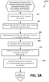
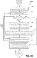
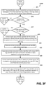
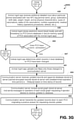
FIGs. 3A-3B depict a logical flow chart illustrating a method for tracking NFC-enabled animals with a portable computing device when animal management software is not detected on the portable computing device according to one exemplary embodiment of the invention. -
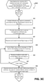
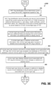
Figs. 3C-3G are continuation flowcharts of the ones illustrated inFigs. 3A-3B and further illustrate a method for tracking NFC-enabled animals with a portable computing device when animal management software is detected and running on the portable computing device according to one exemplary embodiment of the invention. -
FIG. 4 illustrates an exemplary embodiment of the mechanical coupling depicted inFIG. 1A according to one exemplary embodiment of the invention. -
FIG. 5 illustrates additional exemplary embodiments of the mechanical coupling depicted inFIG. 1A according to the invention. -
FIG. 6 illustrates an exemplary embodiment of both an RFID tag and an NFC-tag at a rivet point of the ear tag; -
FIG. 7 illustrates an exemplary embodiment of both an RFID tag and an NFC-tag within an ear tag similar to the exemplary embodiment ofFIG. 6 ; -
FIG. 8A illustrates an exemplary embodiment of both an RFID tag and an NFC-tag at a rivet point of a button type ear tag; -
FIG. 8B illustrates a functional block diagram of one exemplary embodiment of circuitry that may form either an RFID chip or an NFC chip, or a chip that has a pair of dual circuits [two duplicates of the single circuit shown] inFIG. 8B for supporting both NFC and RFID communications; -
FIG. 9 illustrates one exemplary portable computing device of the system ofFIG. 1A according to one exemplary embodiment of the invention. -
FIG. 10 illustrates one exemplary computer of the system ofFIG. 1A according to one exemplary embodiment of the invention. -
FIG. 11A illustrates one exemplary embodiment of an implantable or ingestible RFID tag according to principles of the present invention. -
FIG. 11B illustrates one exemplary embodiment of an implantable or ingestible NFC tag according to principles of the present invention. -
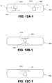
FIG. 12A-1 illustrates one exemplary embodiment of a single encasement for an implantable or ingestible NFC tag and RFID tag having separate chips and separate antennas according to principles of the present invention. -
FIG. 12B-1 illustrates one exemplary embodiment of a single encasement for an implantable or ingestible NFC and RFID tag combination which has a common chip but separate antennas according to principles of the present invention. -
FIG. 12C-1 illustrates one exemplary embodiment of asingle encasement 60 for implantable or ingestible NFC and RFID tags having a common chip and common antenna for both tag functions. -
FIG. 12A-2 illustrates one exemplary embodiment of a single encasement for implantable or an ingestible NFC tag andRFID 50 with separate chips and separate antennas following the exemplary embodiment illustrated inFIG. 12A-1 . -
FIG. 12B-2 this figure illustrates one exemplary embodiment of a single encasement for an implantable or ingestible NFC tag and RFID tag with acommon chip 4000 and separate antennas following the exemplary embodiment illustrated inFIG. 12B-1 . -
FIG. 12C-2(i) illustrates one exemplary embodiment of a single encasement for an implantable or ingestible NFC tag and RFID tag with a common chip and a single, common antenna for both tags following the exemplary embodiment illustrated inFIG. 12C-1 . -
FIG. 12C-2(ii) illustrates one exemplary embodiment of a single encasement for an implantable or ingestible NFC tag and RFID tag having a common chip and a single antenna for both tags following the exemplary embodiment illustrated inFIG. 12C-1 . -
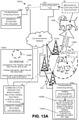
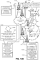
FIG. 13A illustrates a first exemplary embodiment of a subsystem that may be part of the system ofFIG. 1A which may track companion animals and alert owners of lost companion animals. -
FIG. 13A illustrates a second exemplary embodiment of a subsystem that may be part of the system ofFIG. 1A which may track companion animals and alert owners of lost companion animals. -
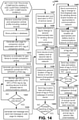
FIG. 14 is a flow chart illustrating a method for tracking companion animals and alerting owners of lost companion animals. - The term "exemplary" is used herein to mean "serving as an example, instance, or illustration." Any aspect described herein as "exemplary" is not necessarily to be construed as preferred or advantageous over other aspects.
- In this description, the term "application" may also include files having executable content, such as: object code, scripts, byte code, markup language files, and patches. In addition, an "application" referred to herein, may also include files that are not executable in nature, such as documents that may need to be opened or other data files that need to be accessed.
- The term "content" may also include files having executable content, such as: object code, scripts, byte code, markup language files, and patches. In addition, "content" referred to herein, may also include files that are not executable in nature, such as documents that may need to be opened or other data files that need to be accessed.
- As used in this description, the terms "component," "database," "module," "system," "engine", and the like are intended to refer to a computer-related entity, either hardware, firmware, a combination of hardware and software, software, or software in execution. For example, a component may be, but is not limited to being, a process running on a processor, a processor, an object, an executable, a thread of execution, a program, and/or a computer.
- By way of illustration, both an application running on a computing device and the computing device may be a component. One or more components may reside within a process and/or thread of execution, and a component may be localized on one computer and/or distributed between two or more computers. In addition, these components may execute from various computer readable media having various data structures stored thereon.
- The components may communicate by way of local and/or remote processes such as in accordance with a signal having one or more data packets (e.g., data from one component interacting with another component in a local system, distributed system, and/or across a network such as the Internet with other systems by way of the signal).
- Referring now to the drawings, wherein the visuals are for purposes of illustrating certain exemplary embodiments of the present disclosure only, and not for purposes of limiting the same,
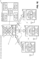
FIG. 1 is functional block diagram of anexemplary system 101 for tracking a plurality of NFC-enabledanimals 65 with aportable computing device 101 according to one exemplary embodiment of the invention. Specifically, theanimals 65 may have atag system 45 that attaches to theanimal 65 via amechanical coupling 60. Themechanical coupling 60 may take many forms/structures/embodiments and is described in further detail below in connection withFIGs. 4-8 . - The
animal 65 may comprise any type of animal. Exemplary animals include, but are not limited to, dogs, fox, cats, ferrets, raccoons, wildcats, calves, cows, piglets, sheep, pigs, hogs, boars, horses, oxen, zebras, camels, dromedaries, lamas, ostriches, deer, elks, moose, monkeys, chicken, hens, turkeys, geese, and various species of birds; tuna, dolphins, sharks, and various species of fish; lions, panthers, puma, etc.Production animals 65 as well ascompanion animals 65 may be well suited forsystem 101.Production animals 65 usually include, but are not limited to, calves, cows, piglets, sheep, pigs, hogs, horses, chickens, hens, turkeys, and geese.Companion animals 65 usually include, but are not limited to, dogs and cats. - The
tag system 45 may comprise a radio-frequency (RF) identifier (RF-ID) tag 50 [that follows standards set for RF-ID tags] as well as a near-field communication (NFC)tag 55. Eachtag own antenna tag antennas ID reader 70 and aportable computing device 100 via itsown antenna 67A. Thetag antennas communication links FIG. 1A may comprise either wired or wireless links. For communication links 103 that exist betweenantennas 67, such links are usually the wireless type. - The RF-
ID tag 50 may be coupled/operably connected to the NFC-tag 55 as indicated by dashedline 27A. This dashedline 27A indicates that this coupling between the NFC-tag 55 and RF-ID tag 50 is optional. In some exemplary embodiments, eachtag tag other tag tags FIGs. 6-8 . - Each
tag other tag line 27B. This cut-line 27B is illustrated with dashes to indicate that the physical separation among the twotags tags tags - The RF-
ID reader 70 that reads the RF-ID tag 50 may comprise off-the-shelf hardware and/or software. For example, the RF-ID reader 70 may comprise a hand-held wand type and/or it may be part of another device/machine such as a scale for weighing aproduction animal 65, like cattle. The RF-ID reader 70 may further comprise a radio-frequency (RF)transceiver 75 for communicating with another wireless device, such as thePCD 100. According to one exemplary embodiment, theRF transceiver 75 may comprise one that is suitable for an industry standard wireless communication, such as BLUETOOTH™ type/brand of wireless communications. Thus, the communication link 103C illustrated inFIG. 1A may comprise a wireless BLUETOOTH™ communication link between theRF transceiver 75 and theantenna 67A of thePCD 100. Other industry standard wireless communications, besides BLUETOOTH™ communications, are possible and are within the scope of this disclosure and are understood by one of ordinary skill in the art. - The
PCD 100 may comprise a cellular telephone, a smartphone, a portable digital assistant (PDA), a portable game console, a navigation device, a tablet computer/PC, a fitness computer, and a wearable device (e.g., a sports watch, a fitness tracking device, etc.) or other battery-powered devices with a wireless connection or link. According to one exemplary and preferred embodiment, theportable computing device 100 may comprise a hand-held, smartphone that runs a high-level operating system (HLOS). - The HLOS may comprise the ANDROID™ brand operating system or the APPLE™ brand mobile phone operating system known as of this writing. The
PCD 100 may also comprise a laptop or tablet PC as understood by one of ordinary skill in the art. One advantage of thesystem 101, according to one exemplary embodiment, is that thePCD 100 is a hand-held device (i.e. is easily carried with a single-hand) and can be carried by a person when he/she may be out outdoors tending toproduction animals 65 or inside a building like a barn. Buildings for production animals 65 [and even outdoors] may not have traditional furniture/set-up for supporting/holding larger non-portable devices, such as desktop computers or laptop computers, that are needed for tracking theproduction animals 65 havingtags - The hand-held
PCD 100 may execute/run an animalmanagement software application 110 that is coupled to a local/internal animal records database(s) 115A. The animalmanagement software application 110 may be coupled to the local animal records database(s) 115A by an internal communications link 107C. The animalmanagement software application 110 may facilitate communications between thePCD 100 and thetag system 45 and theRF transceiver 75 of the RF-ID reader 70 using wireless communication links 103C, 103D. Further details about the data transferred using thesecommunication links 103C, 103D will be described below in connection with the several flow charts. - The animal
management software application 110 helps track the data stored and associated with thetag system 45 of eachanimal 65. Such tracking of data is very helpful in the production animal context when hundreds and sometimes thousands ofanimals 65 and their associated records are needed for efficient management of a production animal facility. - Exemplary records/data that are managed by the
application 110 and which may be contained within the localanimal records database 115A stored locally on thePCD 100 may include parameters such as, but not limited to, height, length, width, girth, weight, color, fertility status (i.e. - pregnant, not pregnant...etc.) and other physical characteristics of the animal, as well as treatments, such as vaccine data, drug treatment data, cleanings, health issues, feeding information etc. According to one exemplary and unique aspect of thesystem 101 is that the localanimal records database 115A stored within asingle PCD 100 may be one-hundred percent (100%) complete for an entire animal production facility. - That is, the local
animal records database 115A stored locally on a hand-heldsingle PCD 100 may contain all records for all animals which may be part of particular production facility, like a single farm/ranch. For example, suppose a farm has one-hundredanimals 65 and there is a record for eachanimal 65. According to one exemplary embodiment, each localanimal records database 115A stored on a hand-heldPCD 100 would have all one-hundred records for the one-hundredanimals 65 for that single farm. - As noted above, the local
animal records database 115A may be stored within eachPCD 100 if a plurality ofportable computing devices 100 are being used for a single animal production facility, like a farm. This means, that each instance of the localanimal records database 115A present on each hand-heldPCD 100 would be the same and would be complete (contains all records for everyanimal 65 on the farm being monitored and which has a NFC-tag 55). - When an individual record for a
single animal 65 is being updated on a first hand-heldPCD 100, then this update to this record is then re-transmitted to the other, second hand-heldportable computing devices 100 on the farm using thecommunications network 150 as will be described in more detail below. This means that one instance of the localanimal records database 115A may stored remotely in a remote animal records database(s) 115B on acomputer server 35 as will be described in more detail below. - In addition to communicating with the RF-
ID reader 70 via the communications link 103C and the RF-ID tag 55 via communications link 103D, each hand-heldPCD 100 may also communicate with otherremote devices 100 via a wireless communications link 103B. The wireless communications link 103B may couple thePCD 100 to acommunications network 150. - The
communications network 150 may comprise a wide area network ("WAN"), the plain-old-telephone-system ("POTS), a local area network ("LAN"), the Internet, or any combination of these and other types of networks. Through thenetwork 150, theportable communication device 100 may communicate with an animal management software developer customer resource management (CRM)server 10; an animal management softwareapplication production server 15; an animal management softwareapplications store server 20; a domain name server (DNS) 22; one or more NFC-tag identification servers communication server 35; and animalmanagement software server 40. - Each of the
computer servers PCD 100 may support various submethods/routines which are part of a larger method for tracking a plurality of NFC-enabledanimals 65. Each of theservers FIG. 10 , described in further detail below. - In a particular aspect, one or more of the method steps described herein may be implemented by executable instructions and parameters, stored in the memory of the
PCD 100 and theservers system 101. These instructions that form thetracking system 101 may be executed by the CPUs 802 [FIG. 9 ], 121 [FIG. 10 ] or any other processor. Further, the processors 802, 121, the memory 815, 122, the instructions stored therein, or a combination thereof may serve as a means for performing one or more of the method steps described herein. - Referring back to
FIG. 1A , the animal management software developer customer resource management [hereafter, "CRM server"]server 10 may manage and store records of the customers who have purchased licenses for and who have downloaded the animalmanagement software application 110 for theirportable computing devices 100. TheCRM server 10 may provide account management services where a user, such as a legal entity, like a company that runs a production animal facility, such as a farm, may monitor and add/delete users/employees who download the animalmanagement software application 110 to their respective portable computing devices 100 (i.e. phones 100). TheCRM server 10 may also provide billing/accounting services for managing the software licensing fees. TheCRM server 10 may also manage user information such as, but not limited to, user identity information like name of company, company address, company phone numbers, company e-mail addresses, fax numbers etc. - The
CRM server 10 may be in communication with the animalmanagement software server 40 as indicated bycommunication link 107D, which maybe a wired or wireless link, supported by thecommunications network 150. Whilecommunication link 107D is illustrated inFIG. 1A as a direct link betweenCRM server 10 and animalmanagement software server 40, thislink 107D may be provided/established by thecommunications network 150. The animalmanagement software server 40 may provide for login/credentials management for the animalmanagement software application 110 that runs on eachPCD 100. For example, the animalmanagement software server 40 may communicate with the animalmanagement software application 110 to generate the login-screen illustrated inFIG. 2D (described in further detail below). - Referring back to
FIG. 1A , the animal management software application production website/server [hereafter, "production server"] 15 may provide for roll-outs/updates to the animalmanagement software application 110 which may be "sold"/downloaded from an animal management software application store/website 20. Theproduction server 15 may allow computer programmers to generate new versions and/or updates to the downloadable animalmanagement software application 110 that is typically run/executed on a hand-heldPCD 100, such as amobile phone 100. - The
production server 15 may communicate with the animal management software application store/website [hereafter, "on-line application store"] 20 as indicated by communications link 107A. This communications link 107A may be established/supported by thecommunications network 150. Theproduction server 15 may send new versions/updates for the animalmanagement software application 110 that is sold and ready for download from the on-line application store 20 to aPCD 100. - According to one exemplary embodiment, the animal
management software application 110 may be designed such that it is unique for particular jurisdictions in which theanimal software application 110 is used. For example, a first version of theanimal software application 110 may have unique features/functions that are particular to a first jurisdiction, such as the country of Canada. A second version of theanimal software application 110 may have unique features/functions that are particular to a second jurisdiction, such as the country of the United States [seeFIG. 1D for a map and exemplary jurisdictions described in more detail below]. - This means an on-
line application store 20 may be physically located in each jurisdiction and/or it may be designed to service/support animalmanagement software applications 110 based on the location information found within thesoftware application 110 and/or each NFC-tag 55 on ananimal 65 within a jurisdiction. Further details about the jurisdictional nature of thesystem 101 will be described below. - Referring again to
FIG. 1A , a domain name service (DNS)server 22 is coupled to thecommunications network 150 and may communicate with thePCD 100. TheDNS server 22 has a universal resource locater (URL) assigned to it and this URL may be stored on each NFC-tag 55. - This URL may also contain jurisdiction information such as an abbreviation of the jurisdiction associated with the NFC-tag 55 (i.e. "US" for United States, "CA" for Canada, etc.). When an NFC-
tag 55 is scanned by a hand-heldPCD 100 which does not have anyanimal management software 110 installed (i.e. not running or not present), the HLOS of thePCD 100 will receive the URL from the NFC-tag 55 and then open a web browser of the HLOS for theportable computing device 100 using the URL. - However, if a hand-held
PCD 100 has an existing account and is running/executing theanimal management software 110, theanimal management software 110 may recognize an NFC-tag 55 based on a tag identifier and thesoftware 110 may direct the communications link for thePCD 100 to acommunication server 35 associated with the account and within an appropriate jurisdiction. But if the hand-heldPCD 100 does not have theanimal management software 110 or the portable computing device has theanimal management software 110 which does not recognize a scanned NFC-tag 55, theanimal management software 110 may indicate the NFC-tag 55 is not recognized for the account and it may instruct the operator to contact theCRM server 10 to see if more information may be available from theCRM server 10 and/or the operators of thatserver 10. - In addition to storing
Tag Identification servers 25 that are associated with jurisdictions assigned to NFC-tags 55, theDNS server 22 also stores the failure/redundancy plan for eachTag Identification server 25. This failure/redundancy plan for the jurisdiction-basedTag Identification servers 25 is described in further detail below in connection withFIGs. 1C-1D . The failure/redundancy plan helps maintain continuity of thesystem 101 should a particularTag Identification Sever 25 be "off-line"/not available for service. - After a hand-held
PCD 100 which does not have theanimal management software 110 orsoftware 110 does not recognize the tag identifier for a particular NFC-tag 55, the URL of a scanned NFC-tag 25 may be sent by the portable computing device to theDNS server 22 and based on the jurisdiction information in the URL, theDNS server 22 will relay an internet protocol (IP) address for an NFC-tag identification server 25 that is assigned to the jurisdiction to thePCD 100. The internet browser of thePCD 100 will then relay the NFC scanned data from NFC-tag 55 to the NFC-tag identification server 25 based on the IP address received from theDNS server 22. - The NFC-
tag identification servers 25A-25C are coupled to thecommunications network 150. Each NFC-tag identification server 25 may store NFC-tag identifiers present on each NFC-tag 55 of ananimal 65. As discussed above, each NFC-tag identification server 25 is physically located within a jurisdiction (i.e. a country - as indicated byarrow 30 which denotes multiple countries/jurisdictions may exist) and is associated with NFC-tags 55 that are also assigned to the jurisdiction (i.e. usually a country). - When the NFC-
tag Identification Server 25 receives NFC-tag data from aPCD 100 which does not have theanimal management software 110, the NFC-tag identification server 25 may generate a welcome page and direct the operator of thePCD 100 to an appropriate on-line store server 20. An appropriate on-line store server 20 may sell the animal management software 110 [available for downloading] that corresponds with the jurisdiction assigned to the scanned NFC-tag 55. Such a welcome page is illustrated inFIG. 2B described in further detail below. - Once a hand-held
PCD 100 has downloadedanimal management software 110 appropriate for its jurisdiction (based on the jurisdiction assigned to each NFC-tag 55 being scanned by the portable computing device), then the animal management software may establish asecure communication link 103B over thecommunications network 150 to the animalmanagement software server 40 and thecommunication server 35. - The animal
management software server 40 is coupled to thecommunications network 150 via a communications link. The animalmanagement software server 40 is illustrated with a direct communications link 107B to thecommunication server 35. This direct communications link 107B may be virtual and may be established by thecommunications network 150. The communications link 107B is depicted to denote that the animalmanagement software server 35 controls access to thecommunications server 35. The animalmanagement software server 35 may communicate directly with each instance ofanimal management software 110 running on aportable computing device 100, such as amobile phone 100. - The animal
management software server 35 may facilitate a secure communications channel over thecommunications network 150 between the animalmanagement software application 110 running on thePCD 100 and thecommunication server 35 which may maintain a remote animal record(s)database 115B. The remote animal record(s)database 115B corresponds with the localanimal records database 115A present on eachPCD 100, like a mobile phone. Further details about the remote animal record(s) database will be described below in connection withFIGs. 1E-1F . - The secure communications channel between the
PCD 100 andcommunication server 35 facilitated/established by the animalmanagement software server 40 may be encrypted according to off-the-shelf and/or conventional cryptographic standards known as of this writing. The animalmanagement software server 40 may generate the log-in screen ofFIG. 2D that is displayed on aPCD 100 when a PCD desires access to its localanimal records database 115A present on thePCD 100. The log-in screen ofFIG. 2D is described below in further detail. - Once the animal
management software server 40 grants aPCD 100 access to its localanimals records database 115A present on thePCD 100, the animalmanagement software server 40 also grants access to thecommunication server 35 and the remote animal record(s)database 115B. According to one exemplary aspect of thesystem 101, the remote animal record(s)database 115B at thecommunication server 35 helps a plurality ofPCDs 100 maintain complete records ofanimals 65 when a plurality ofPCDs 100 are deployed for managing an animal production facility, like a farm. In other words, thecommunication server 35 and its remote animal record(s)database 115 helps eachPCD 100 to have a local animal record(s)database 115B that is identical to anotherPCD 100 whenmultiple PCDs 100 are used to manageproduction animals 65 at an animal production facility, like a farm. Further details on how thecommunication server 35 and its remote animal record(s) database help manage the animal data managed acrossmultiple PCDs 100 is described in further detail below in connection withFIGs. 1E-1F . - Referring now to
FIG. 1B , this figure illustrates exemplary NFC-tag data 59 which may be stored within each of the NFC-tags 55 of thesystem 100 illustrated inFIG. 1A . Exemplary NFC-tag data 59 may include, but is not limited to, (i) a Universal Resource Locater (URL); (ii) a unique tag identifier; (iii) an NFC scan count; and (iv) a sub-domain-Salt Key. Additional or fewer data elements may be stored on each NFC-tag 55 as understood by one of ordinary skill in the art. - The URL element of the NFC-
tag data 59 may comprise one, as described above, which is recognized and translated by theDNS server 22. The URL may take the format of "jurisdiction.tag.vet" in which the last three characters of the domain direct an internet browser to theDNS server 22. The DNS server then reviews the "jurisdiction" sub-domain in order to provide an IP address based on the "jurisdiction" data. The jurisdiction data usually comprises a country code, such as "US" for United States, "CA" for Canada, etc. - The unique tag identifier may comprise an alpha-numeric string of characters that are assigned to a particular NFC-
tag 55 during its manufacture/production. The unique tag identifier may be stored at eachTag Identification Server 25 as described above so that aPCD 100 is directed to an appropriate, jurisdiction-based on-line store 20 so that jurisdiction-basedanimal management software 110 may be downloaded that matches the jurisdiction of the NFC-tag 55. - The
tag data 59 may further comprise a scan count that is updated and stored on the NFC-tag 55. Each NFC-tag 55 may comprise a memory module/element 440 which stores the NFC-tag data 59 as illustrated inFIG. 8B described in further detail below. Thememory module 440 may be updated to track changes such as changes in the scan count. The scan count may track how many times the NFC-tag 55 is scanned by a reader such as by a reader present on aPCD 100. This scan count may be used as a security parameter as understood by one of ordinary skill in the art. - The NFC-
tag data 59 may further comprise a salt key. This salt key may prevent counterfeit/unauthorized duplicates and/or production of NFC-tags 55 as understood by one of ordinary skill in the art. As noted previously, additional or less NFC-tag data 59 may be stored on each NFC-tag 55 as apparent to one of ordinary skill in the art. - Referring now to
FIG. 1C , this figure illustrates exemplary data which may be stored on a domain name service (DNS)server 22 in thesystem 101 ofFIG. 1A . This figure also illustrates a failure/redundancy plan 27 for each NFC-tag identification server 25 of thesystem 101 illustrated inFIG. 1A . As noted previously, theserver 22 directs an internet browser of aPCD 100 to the appropriate jurisdictional-basedtag identification server 25 in response to the URL data received from a particular NFC-tag 55. Eachtag identification server 25 may provide a web page and a link [such as illustrated inFIGs. 2A-2B described in further detail below]. - If a NFC-
tag identification server 25 is down/offline for a first jurisdiction, theDNS server 22 may receive this status and then re-direct thePCD 100 to a second jurisdiction according to the failure/redundancy plan 27. For example, thefirst redundancy plan 27A is for a first jurisdiction which is the country of Canada. See alsoFIG. 1D which illustrates the exemplary embodiments of jurisdictions in the form of countries. - According to this exemplary embodiment for a
first redundancy plan 27A, the first line lists the IP address for a firstTag identification server 25A located in the first jurisdiction, which is Canada for this example. This first line of theplan 27A (line i) is what is relayed to aPCD 100 when theDNS server 22 re-directs the internet browser of thePCD 100 which just scanned an NFC-tag 55 that contains the URL data described above. If theDNS server 22 receives a status that one or morefirst servers 25A in the first jurisdiction (i.e. such as Canada) are down/off-line, then theDNS server 22 goes to the next line in theplan 27A (line ii ofFIG. 1C ]. - In the exemplary embodiment for the
first plan 27A, this second line ii of the plan instructs theDNS server 22 to provide the IP address of theserver 25B which is located in the second jurisdiction (which is the United States) for this example. If theDNS server 22 detects and/or is informed that the secondTag identification server 25B in the second jurisdiction (see also FIG. ID) is also down/off-line, then theDNS server 22 goes to the next line in theplan 27A which is line iii in thisplan 27A. Line iii ofplan 27A instructs theDNS server 22 to provide the IP address of a Tag identification server 25C located in the third jurisdiction (which is the country of Great Britain in this example). - Each Tag identification server failure/redundancy plan 27 as illustrated in
FIGs. 1C-1D may be setup/created by the owner of an account for a particular animal production facility. Alternatively, each plan 27 may be controlled/set by governments of each jurisdiction. Usually, since regulations/laws may vary from one jurisdiction to the next, the failure/redundancy plan 27 may be created such that back-upTag identification servers 25 listed in the plan 27 have regulations/laws similar to the primaryTag identification server 25. - Referring now to
FIG. 1D , this figure illustrates respective exemplary geographic locations for each NFC-tag identification server 25 that are illustrated in thesystem 101 ofFIG. 1A according to one exemplary embodiment of the invention. Eachtag identification server 25 may have its own back-up/redundancy plan 27 which is stored at the DNS server 22 (as illustrated inFIG. 1C ) and/or is accessible by theDNS server 22. Each plan lists IP addresses ofother servers 25 which may be provided as a back-up/redundancy in case of failure/problems for a particularTag identification server 22. Further details of each plan have been described above in connection withFIG. 1C . - While only the jurisdictions of Canada, the United States, and some European countries have been illustrated in
FIG. 1D , other countries/geographical locations are possible and are included within the scope of this disclosure. Thesystem 101 is also not limited to country-based jurisdictions. Sub/smaller jurisdictions are possible, such as provinces within a country and/or states (such as within the United States). For example, single states within a country like the United States may be used as jurisdictions. Groups of states/countries are also possible in order to form special jurisdictions. A jurisdiction may be formed from any combination of geographical regions as understood by one of ordinary skill in the art. - Each jurisdiction-based
tag identification server 25 may perform replication of tag data as well as detailed animal record data with anotheridentification server 25 for data redundancy. Such replication may be performed asynchronously as understood by one of ordinary skill the art. As noted above,servers 25 are typically physically present within certain geographic territories. Any replication of data among theservers 25 may occur locally meaning onlyservers 25 in the same geography will usually support the redundant data. Replication amongservers 25 in different jurisdictions may also occur and/or follow the DNS server failure/redundancy plan as described above in connection withFIGs. 1C-1D . - Referring now to
FIG. 1E , this figure illustrates how the electronic records maintained by thesystem 101 ofFIG. 1A may be accessed off-line in addition to howsocial graphs 81 may be created to enable access and sharing of electronic records within thesystem 101. As noted previously, the local animal records database(s) 115 maintained on eachPCD 100 associated with a single animal production facility (i.e. a farm/ranch) may be identical, according to one exemplary embodiment of thesystem 101. - So, as an example, if there are one-hundred
production animals 65 at a facility, there would usually be at least one-hundred records stored within each local animal records database(s) 115 stored on eachPCD 100. There would be at least one record for eachanimal 65. Each record may have a plurality of fields as described above, such as, but not limited to, fields like height, length, width, girth, weight, color, fertility status (i.e. - pregnant, not pregnant...etc.) and other physical characteristics of the animal, as well as treatments, such as vaccine data, drug treatment data, cleanings, health issues, feeding information etc. - This means that a first local animal records database 115A1 stored on a first hand-held
PCD 100A would be identical to a second local animal records database 115A2 stored on a second hand-heldPCD 100B, as well as the local animal records database 115A3 stored on a third hand-heldPCD 100C. Each of these local databases 115A1-A3 may be kept/maintained as identical by thecommunication server 35 which may keep one or more instances of the animal records maintained within a remoteanimal record database 115B. - As a single record for an
animal 65 is updated by aparticular PCD 100, thecommunication server 35 may track which individual animal records are stored on eachPCD 100. For example, if afirst PCD 100A updates a first record for a first animal that is stored in the local database 115A1, thefirst PCD 100A via theanimal management software 110 may send that updated first record over the communications network 150 (seeFIG. 1A ) to thecommunications server 35 as denoted by the communications link arrow AA. - The
communications server 35 may store the updated first record received from thefirst PCD 100A in its remoteanimal records database 115B. Then, at later time windows, thecommunications server 35 can determine if thesecond PCD 100B and thethird PCD 100C need this updated first record for their respective local animal records databases 115A2, 115A3. Thecommunications server 35 can determine when thesecond PCD 100B and thethird PCD 100C need the updated first record when they establish a communications link with thecommunications server 35. - The
communications server 35 may track the status of the records of the local animal record databases 115A1-115A3 in various ways. According to one exemplary embodiment, thecommunications server 35 may flag/highlight those animal records which have been updated by afirst PCD 100A. Then when second and thirdportable computing devices server 35, theserver 35 may request eachPCD animal records database 115B maintained at theserver 35. - If the
server 35 determines that a localanimal records database 115A does not have an updated record, then it may transmit that updated record from the remoteanimal record database 115B over thecommunications network 150 to eachrespective PCD 100 which may need the updated record as indicated by communication links arrows BB and CC inFIG. 1E . - When a
PCD 100 first comes on-line/is activated or if thePCD 100 ever loses data, then the localanimal records database 115A may be empty. In that situation, thesever 35 may download the entire set of records from the remoteanimal record database 115B over thecommunications network 150 to eachrespective PCD 100 which may need the complete set of records as indicated by communication links arrows BB and CC inFIG. 1E . - When a
PCD 100 establishes a communication link with thecommunication server 35, thecommunication server 35 determines a level of access to theremote records database 115B available to arespective PCD 100 by reviewing security parameters which may be part of asocial graph 81. According to an exemplary embodiment of thesocial graph 81 illustrated inFIG. 1E maintained by thecommunications server 35, three levels of access are provided: a first access level A; a second access level B; and a third access level C. - The first access Level A may permit the updating/editing of animal records as well as access to all animal records in the remote
animal records database 115B. The first access Level A may provide the highest/most complete access to the remoteanimal records database 115B. This level may be assigned to manager(s) (MANAGER 1) and/or employees (EMPLOYEE #1) as well as veterinarian(s) (VET #1) associated with a particular animal production facility (i.e. a farm). - The second access Level B may provide for an intermediate/less robust access relative to the first access Level in connection with the remote
animal records database 115B. This level may be assigned to less important/newer/lower-level employees (EMPLOYEE #2) associated with a particular animal production facility (i.e. a farm). According to this access Level B, records in the remoteanimal record database 115B as well those as stored in the localanimal records database 115A on aportable computing device 100 may be viewed but not changed/edited. The entire database of animal records may be viewed but cannot be edited with this second access Level B. According to this second access Level B, theentire database 115 of animal records may be stored in the localanimal record database 115B on aPCD 100. - The third access Level C may provide for lowest access relative to the first access Level in connection with the
remote animal database 115B. This level may be assigned to non-employees/potential animal buyers (Buyer #1) associated with a particular animal production facility (i.e. a farm). According this third access Level C, only select records in the remoteanimal record database 115B as well those as stored in the localanimal records database 115A on aPCD 100 may be viewed. - This means that usually the manager having the first access Level A will select a certain number of animal records, usually less than the entire database, that can only be viewed by a
PCD 100 having the third access Level C. According to this third access Level C, theentire database 115 of animal records may not be stored in the localanimal record database 115B on aportable computing device 100. Instead, aPCD 100 having the third access Level C may only be able to access the remoteanimal records database 115B ofserver 35 -- and cannot download the records permanently to thePCD 100. - While three levels of access are described above, one of ordinary skill in the art recognizes that fewer levels or additional levels of access are possible and are included within the scope of this disclosure. Further, variations in the types of access for each level are possible and are included within the scope of this disclosure as understood by one of ordinary skill in the art.
- According to one exemplary benefit of
system 101 which has thecommunication server 35 having the remoteanimal records database 115B and the localanimal records database 115A stored on eachPCD 100, thecomplete database 115 of animal records is usually stored on each of thesedevices devices database 115 from onedevice - In
FIG. 1E , a dashed "X" 177 has been illustrated to denote that thecommunication server 35 could suffer some form of failure/break-down or this dashed "X" may denote that thecommunications network 150 is down and that none of theportable computing devices 100 may be able to establish a communication link with theserver 35. Since eachPCD 100 having the appropriate access level may have a complete set of animal records in itslocal database 115A, then eachPCD 100 may function for some time without the need for communicating withserver 35. - When the
communication server 35 goes off-line as indicated by the dashed "X" 177, each of theportable computing devices 100 may rely on device-to-device communications, indicated by arrows DD and EE, such as point-to-point (P2P) Bluetooth communications or a WiFi direct synchronous mode protocols as understood by one of ordinary skill in the art. That is, each of theportable computing devices 100 may communicate with one another directly thecommunications server 35 is offline. Each of theportable computing devices 100 may exchange its respective local animal records with anotherportable computing device 100 when thecommunications server 35 is off-line. - In a scenario where the remote
animal records database 115B may have been damaged/destroyed/erased, but then put back on-line, thesystem 101 allows for the rapid replication of animal records. As noted above, each PCD 100 (which may have the first or second access levels A or B described above) may have complete set of animal records in its respective localanimal records database 115A which can be uploaded/communicated to thecommunication server 35. Thecommunication server 35 can re-populate/re-install its entire remoteanimal records database 115B by using any one of the records that may be supplied from a localanimal records database 115 supplied from aPCD 100 across thecommunications network 150. - Referring now to
FIG. 1F , this figure illustrates how the electronic records supported by thesystem 101 ofFIG. 1A may be stored locally within theportable computing devices 100 which run the animalmanagement software application 110 according to one exemplary embodiment of the invention.FIG. 1F is similar toFIG. 1E , therefore, only the differences between these two exemplary embodiments will be described below. - According to this exemplary embodiment, compared to
FIG. 1E , instead of theserver 35 having some form of failure as indicated by the dashed "X" 170, asecond PCD 100B may suffer some form of failure and it may lose the records of its localanimal record database 115A. Like the scenario described above in connection withFIG. 1E , thesecond PCD 100B may restore its local database 115A2 from animal records supplied from any one of the local databases 115A1 and 115A3 of the first and thirdportable computing devices animal records database 115B stored at theserver 35. - Two arrows with roman numeral (i) have been provided to illustrate how records from local animal records databases 115A1, 115A3 could be uploaded over the
communications network 150 to thecommunications server 35. As indicated by the arrow denoted with roman numeral (ii), thecommunication server 35 may relay the animal records it receives from theportable computing devices communications network 150 to thesecond PCD 100B in order to restore the animal records in its local animal records database 115A2. - Alternatively, or in conjunction with
communication server 35, theportable computing device 100A and theportable computing device 100C may communicate directly with one another, as indicated by arrow (iv), instead of/or in addition to their respective communication links to thecommunication server 35 indicated by the two arrows labeled (i). Each of theportable computing devices 100 may rely on device-to-device communications such as point-to-point (P2P) Bluetooth communications or WiFi direct synchronous mode protocols as understood by one of ordinary skill in the art, as noted above inFIG. 1E . The device-to-device communications may allow for the exchange of local animal records amongportable computing devices 100. - Referring now to
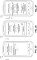
FIG. 2A , this figure illustrates anexemplary screenshot 202A of aPCD 100 after it conducts a scan of an NFC-tag 55 and when thePCD 100 does not have theanimal management software 110 installed in its memory. As described above in connection withFIG. 1A , if aPCD 100 scans an NFC-tag 55 without having theanimal management software 110, then the high-level operating system (HLOS) of thePCD 100 will receive the NFC-tag data 59 ofFIG 1B , and particularly a URL. - Based on that URL, the HLOS of the
PCD 100 will use its internet browser to access theDNS server 22 using the URL. TheDNS server 22 will then relay to thePCD 100 over thecommunications network 150 the IP address of theTag identification server 25 that is associated with the sub-domain code of the URL (i.e. the country code contained within the URL). - The internet browser of the
PCD 100 will then open a web page found on the Tag identification server 25 (illustrated inFIG. 2B described below). TheTag identification server 25 may display a message such asmessage 204 ofFIG. 2A which has a hypertext link associated with the phrase, "APP STORE# 1" which may be bolded and underlined to denote it as a hypertext link. - Referring now to
FIG. 2B , this figure illustrates anexemplary screenshot 202B of thePCD 100 when the Internet browser of thePCD 100 accesses anapplication store 20 within a jurisdiction that has been identified by the NFC-tag identification server 25 according to one exemplary embodiment. Basically, this screen shot 202B is generated by the animal management softwareapplication store server 20 after the hypertext link produced inmessage 204 by thetag identification server 25 ofFIG. 2A has been selected. - Screen shot 202B may comprise a
message 206 which explains that a NFC-tag 55 supported bysystem 101 has been scanned byPCD 100. However, to access the data found on thetag 55 and any records indatabases 115 associated with thetag 55 may only be made when thePCD 100 has theanimal management software 110. - As noted previously, the appropriate on-line server/
store 20 is referenced/supplied by thetag identification server 25 after an NFC-tag 55 is scanned by adevice 100 which does not have theanimal management software 110. Since each NFC-tag 55 may be managed according to rules, regulations, and/or laws unique to a jurisdiction, theTag identification server 25 supplies a jurisdiction-dependent on-line store 20 which will supplyanimal management software 110 which may be unique for each jurisdiction. The correctTag identification server 25 is located by theDNS server 22 according to the URL data stored within each NFC-tag 55 and received by aPCD 100. -
Screenshot 202B may further comprise ahypertext link 208 which will allow thePCD 100 to download the animalmanagement software application 110. Once thehypertext link 208 is activated, thePCD 100 may be prompted to download the animalmanagement software application 110 to its memory and to execute/run the program. -
FIG. 2C illustrates anexemplary screenshot 202C of aportable computing device 100 after an NFC-tag 55 has been scanned andanimal management software 110 on theportable computing device 100 has been detected by the HLOS of thePCD 100. Thescreenshot 202C may comprise amessage 210 that indicates that the scan of the NFC-tag 55 was valid and that theanimal management software 110 has received the tag data and verifying if thePCD 100 has an authorized account which will allow thePCD 100 to access the localanimal records database 115A which may contain additional records associated with thetag data 59, such as the unique tag identifier. - Referring now to
FIG. 2D , this figure illustrates anexemplary screenshot 202E of theportable computing device 100 when the animalmanagement software application 110 has been opened and prompts the operator for the user credentials of theapplication software 110. According to one exemplary embodiment of thesystem 101, when a manager/lead representative for an account establishes multiple users for the account so that a plurality ofPCDs 100 may access the single account, then the animal managementsoftware CRM server 10 may provide an alpha-numeric code 212. This alpha-numeric code 212 may comprise numbers and/or letters and may have any length. Thecode 212 may authenticate each instance of theanimal management software 110 with thecommunication server 35 to gain access to both the remoteanimal records database 115B maintained by theserver 35 and the localanimal records database 115A maintained on thePCD 100. Usually, theCRM server 10 provides onecode 212 per user/PCD 100. - While the
code 212 may be used to authenticate each instance of ananimal management software 101 on aPCD 100, other authentications methods exist and are within the scope of this disclosure. Other authentication methods include, but are not limited to, public/private key encryption techniques including digital certificates, authenticating by SMS via a mobile phone number, authentication via e-mail, and authentication by a live phone call using a voice recognition system. - Referring now to
FIG. 2E , this figure illustrates anexemplary screenshot 202E of theportable computing device 101 once access to the animalmanagement software application 110 running on the portable computing device has been granted. Thescreenshot 202E may comprise a welcome screen and it may listcommands 216 that may be issued by the operator of thePCD 100. - Referring now to
FIG. 2F , this figure illustrates anexemplary screenshot 202F of theportable computing device 100 once access to the animalmanagement software application 110 running on the portable computing device (PCD) 100 has been granted and after an NFC-tag 55 has been scanned by thePCD 100. According to this exemplary embodiment, thescreenshot 202F displays certain data from the scan. Such data may include the unique NFC-tag identifier 222, which in this example, is thenumber 9781. Usually, theNFC tag ID 22 comprises a fourteen character Hexadecimal number as understood by one of ordinary skill in the art. An example of such a hexadecimal includes, but is not limited to, 04:EE:E5:72:29:49:80. - As noted previously, each NFC-
tag 55 may be assigned aunique tag identifier 222 when thetag 55 is manufactured. Theunique tag identifier 222 may comprise an alpha-numeric string of characters. Theanimal management software 110 may associate other records with thisunique tag identifier 222, such as an animal productionunique identifier 223 in this example (hereafter, "production identifier"). - The
production identifier 223 may also comprise an alpha-numeric string of characters. However, thisproduction identifier 223, which has the value of 1234 in this example ofFIG. 2F , may be created by an employee or manager of the animal production facility -- such as a farm. Usually, theproduction identifier 223 can be entered into theanimal management software 110 in addition to human-readable version that can be hand-written or machine-printed on each NFC-tag 55. - Referring now to
FIG. 2G , this figure illustrates an exemplary home-page screenshot 202G of theportable computing device 100 once access to the animalmanagement software application 110 running on the portable computing device (PCD) 100 has been granted. According to this exemplary embodiment, a message is displayed on thePCD 100 that lists the one or more animal production facilities that a user may have access to in order to create and/or edit animal records stored locally on thePCD 100 as well atcommunication server 35 is described above in connection withFigure 1 . - Referring now to
FIG. 2H , this figure illustrates an exemplary dash-board screenshot 202H of theportable computing device 100 running theanimal management software 110. In this exemplary embodiment, a summary of information tracked for the animals in a production facility may be displayed. For example and as shown, various drugs or chemicals applied to animals of an animalproduction facility # 2 may be tracked. In addition to the tracking of drugs or chemicals,system 101 may also track medical procedures as well as on a non-medical procedures. Exemplary drugs or chemicals, may include, but are not limited to, animal vaccines, parasiticides, antibiotics, vitamins, supplements, hormones, and other active agents and substances. Exemplary medical procedures may include, but are not limited to, spay or neuter status with respect to reproductive organs of animals, artificial insemination status / pregnancy status, and other similar medical procedures/health information for animals. - Referring now to
FIG. 2I , this figure illustrates an exemplary first step of a three step process having ascreenshot 2021 displayed on theportable computing device 100 for adding a printedproduction identifier 223 to an outer surface of anear tag FIGs. 6 and 7 . Thisscreenshot 2021 explains to an operator how anew NFC tag database 115 maintained bysystem 101. Thescreenshot 2021 explains how thenew NFC tag 55 needs to be placed in proximity to thePCD 100 for the scan. - Referring now to
FIG. 2J , this figure illustrates an exemplary second step of a three step process having ascreenshot 202J displayed on theportable computing device 100 for adding a printedproduction identifier 223 to anNFC tag 55. According to this second step which occurs after the scan of theNFC tag 55, the operator of aPCD 100 is prompted to enter data into thescreenshot 202J which comprises the printedproduction identifier 223. As noted previously, the printedproduction identifier 223 which is applied to the outer surface of theNFC tag 55 may be hand-written and/or it may be printed by a printing machine such as by a computer printer. In this second step, the operator of thePCD 100 is supplying the printedproduction identifier 223 into thedatabase 115. - Referring now to
FIG. 2K , this figure illustrates the completion of the exemplary second step of the three step process ofFIG. 2J in which the printedproduction identifier 223 is now displayed on theportable computing device 100 inscreenshot 202K. According to this exemplary embodiment, the printedproduction identifier 223 was assigned a numeric value of 1234 as noted below in connection withFigs. 6-7 . As noted previously, the printedproduction identifier 223 may comprise alphanumeric text (i.e. numbers and/or letters) that may be selected according to the numbering scheme that a particular animal production facility desires to follow and which is independent of the animal records stored in thedatabase 115 thesystem 101. - Referring now to
FIG. 2L , this figure illustrates an exemplary third step of a three step process having ascreenshot 202L displayed on theportable computing device 100 for adding theNFC tag 55 with the newly assignedproduction identifier 223 to a particular animal subgroup tracked at an animal production facility. According to this exemplary embodiment, two animal groups are available in which to classify the newly addedNFC tag 55 which also has the newly assignedproduction identifier 223. Alternatively, instead of adding thenew NFC tag 55 to an existing group of an animal production facility, a new animal group may be created in thedatabase 115 by theportable computing device 100 as indicated by the on screen button listed at the bottom ofFIG. 2L . - Referring now to
FIG. 2M , this figure illustrates anexemplary screenshot 202M displayed on theportable computing device 100 when a new animal group described in connection withFIG. 2L is created. According to this exemplary embodiment, thescreenshot 202M receives input for a name of a new animal group. The name may comprise any one of alphanumeric text, similar to theanimal production identifier 223 described previously. - Referring now to
FIG. 2N , this figure illustrates anexemplary screenshot 202N displayed on theportable computing device 100 which comprises information that can be supplied for the animal attached to the newly addedNFC tag 55 which also has the animalproduction facility identifier 223. Exemplary information stored indatabase 115 associated with anyNFC tag 55 as well as theproduction facility identifier 223 may include, but is not limited to, drugs or chemicals applied to the animal, the weight of the animal, birth records, birth control records, feeding logs, and other health notes. The drugs or chemicals stored in thedatabase 115 may comprise vaccines, parasiticides and other active agents, strengths associated with a vaccines or active agent, and vitamins and other nutrients which may be provided to an animal. - Referring now to
FIG. 2O , this figure illustrates an exemplary screenshot 202O displayed on theportable computing device 100 which comprises additional information that can be supplied for the animal attached to the newly addedNFC tag 55 and which also has the animalproduction facility identifier 223. Additional information that can be stored indatabase 115 and which may be associated with both the NFC tag 55 (its identifier) and theproduction facility identifier 223, may include, but is not limited to, date of birth, a mother or parent identifier used in breeding, animal mating information, read, weight at birth, health notes, as well as other notes. - Referring now to
FIG. 2P , this figure illustrates anexemplary screenshot 202P displayed on theportable computing device 100 which comprises various actions for drugs or chemicals that can be applied toanimals 65 of a production facility. In the exemplary embodiment illustrated inFIG. 2P , a first chemical listed aschemical # 1 has been selected as indicated byarrow 297. The first chemical could be applied in two different stages of animal growth according to the exemplary embodiment illustrated. Note that a third stage of pre-wean is shown but is not available for the three chemicals listed. The two stages of animal growth listed include a weaning stage and a booster stage. According to exemplary embodiment illustrated inFIG. 2P , the booster stage was selected forchemical # 1. - Referring now to
FIG. 2Q , this figure illustrates an exemplaryanimal group screenshot 202Q displayed on theportable computing device 100 in response to the input received in connection with thescreenshot 202P ofFIG. 2P . According to this exemplary embodiment, once an action inscreenshot 202P ofFIG. 2P is selected, then thisscreenshot 202Q is generated to allow the selection of a particular animal group of an animal production facility as desired to be treated. - Referring now to
FIG. 2R , this figure illustrates an exemplarytreatment information screenshot 202R displayed on theportable computing device 100 in response to the input received in connection with thescreenshot 202Q ofFIG. 2Q . According to this exemplary embodiment, details for the treatment/action which was selected inscreenshot 202Q ofFIG. 2Q can be received before the action/treatment to the animal group is applied. Exemplary information for actions/treatments may include, but is not limited to, average approximate animal age for the animal group, administration date for the action/treatment, the name of the treatment/action [i.e. drug name, vaccine name, parasiticide name, etc.], any serial number for the product associated with the treatment/action, and any product expiration date associated with any treatment/action. - Referring now to
FIG. 2S , this figure illustrates a brand/strength screenshot 202S displayed on theportable computing device 100 in response to the input received in connection with thescreenshot 202R ofFIG. 2R . According to this exemplary embodiment,screenshot 202S is generated in response to the chemical name which may be received inscreenshot 202R ofFIG. 2R . InFIG. 2R , the brand and any relative strength of the chemical may be entered into thisscreenshot 202S. - Referring now to
FIG. 2T , this figure illustrates ascreenshot 202T showing a completed record for a selected action/treatment of a particular animal group in an animal production facility. As noted previously, exemplary information for the action/treatment which is stored indatabase 115 may comprise, but is not limited to, the chemical name, the average approximate each for each animal in the animal group, the administration date for the treatment/action on the group, any product name, any brand name, any relative strength of the product, any product serial numbers/lot numbers, and any product expiration dates. - See
FIGs. 6 and 7 which illustrateexemplary ear tags tags production identifiers 223 printed thereon such that theidentifiers 223 are human readable. Theproduction identifiers 223 may be hand-printed or machine printed on thephysical housing 60 which supports the NFC-tag 55. - The
production identifier 223 is yet another exemplary unique feature of thesystem 101. Theproduction identifier 223 may comprise a tracking system/organization system that may be unique to the animal production facility, such as a farm. Meanwhile, in addition to bearing theproduction identifier 223, each NFC-tag 55 may also comprise its unique identifier that is stored in its memory when thetag 55 is manufactured. In this way, an animal production facility may still choose to create its own tracking system/organization system for itsproduction animals 65. However, the tracking system/organization system which is unique to the animal production facility may be managed with the NFC-tags 55 that are associated with the animal production tracking system using theunique identifiers 222 assigned to each NFC-tag 55 when it is manufactured. - Referring now to
FIGs. 3A-3B , these figures depict a logical flow chart illustrating a method 300 for tracking NFC-enabledanimals 65 with aportable computing device 100 whenanimal management software 110 is not detected on theportable computing device 110 according to one exemplary embodiment of the invention. As noted previously, the NFC-tags 55 as well as theanimal management software 110 may be dependent upon/governed by local rules, laws, and/or regulations of a particular jurisdiction. Therefore, thesystem 101 helps the operator of aportable computing device 100 download theappropriate software 110 for the jurisdiction associated with a particular NFC-tag 55. - Referring now to
FIG. 3A , the method 300 begins withstep 301 in which a portable computing device (PCD) 100 may conduct a scan of an NFC-tag 55 with the high-level operating system running on thePCD 100. Subsequently, instep 303, the PCD 100 a receive thetag information 59 as described above in connection withFIG. 1B . As discussed above, thistag information 59 may include, but is not limited to, a URL, a unique tag identifier, and a scan count. - Next, in
step 306, the high-level operating system of thePCD 100 may initiate an Internet browser running on thePCD 100 based upon the URL received from the tag information/data 59. Instep 309, aPCD 100 may transmit the URL over the medications that work 150 to theDNS server 22 as illustrated inFIG. 1A . - Subsequently, in
step 312, theDNS server 22 may retrieve the sub-domain from the URL of thetag data 59 received from thePCD 100 sent over thecommunications network 150. Specifically, the sub-domain may comprise the jurisdiction assigned to the NFC-tag 55. According to one exemplary embodiment of thesystem 101, the jurisdiction usually comprises a country code. However, as noted previously, other jurisdictions are possible and are included within the scope of this disclosure as understood by one of ordinary skill in the art. - Next, in
step 315, theDNS server 22 identifies the Internet protocol address based on the jurisdiction information that theDNS server 22 retrieved from thetag data 59. This Internet protocol address is usually for thetag identification server 25 as described above in connection withFIG. 1A . The selection of the Internet protocol address for the tag identification server is also governed by the failure/redundancy plan 27 also described above in connection withFIG. 1A . - The
method 300A continues fromstep 315 ofFIG. 3A to step 318 ofFIG. 3B (ofmethod 300B). Referring now toFIG. 3B ,step 318 is the first step of this flowchart. - In
step 318, theDNS server 22 transmits the Internet protocol address of the jurisdiction-basedtag identification server 25 over thecommunications network 150 to the Internet browser of thePCD 100. This activity between theDNS server 22 and thetag identification server 25 may be part of a message that is communicated to thePCD 100 as illustrated inFIG. 2A . - In
step 321, the browser of thePCD 100 may transmit the tag information/data 59 to the jurisdiction-basedtag identification server 25 as described above in connection withFIG. 1A . Then, indecision step 324, theDNS server 22 determines if thetag identification server 25 is functioning properly and/or is off-line. TheDNS server 22 may be waiting for a message from theserver 25 and/or theDNS server 22 may wait for a predetermined period of time if there are no communications/responses from thetag identification server 25. - If the inquiry to
decision step 324 is positive, the "yes" branch is followed to step 327. If the inquiry todecision step 324 is negative, the "no" branch is followed to step 339. - In
block 327, theDNS server 22 may send a redirect message to the PCD browser to transmit thetag data 59 again to theDNS server 22. Alternatively, theDNS server 22 may store thetag data 59 in a local memory store (not illustrated) and access this memory store for thisstep 327. - In
block 330, the PCD browser may resend thetag data 59 which may contain the URL over thecommunications network 150 to theDNS server 22. Inblock 333, theDNS server 22 reviews the URL and identifies the next IP address for thetag identification server 25 which is assigned to the sub-domain for that jurisdiction according to a failure/redundancy protocol 27 is described above in connection withFIGs. 1B-1C . - Next, in
step 336, theDNS server 22 may transmit this Internet protocol address selected instep 333 over thecommunications network 150 to the Internet browser of thePCD 100. Themethod 300B then continues back to step 321. - In
step 339, the jurisdiction-basedtag identification server 25 generates a message comprising a welcome page and an HTML link for an on-line store associated with the jurisdiction of the sub-domain where the animalmanagement software application 110 may be sold and downloaded. Thisstep 339 generally corresponds with the message displayed on thePCD 100 as illustrated inFIG. 2A . - The
method 300B then continues toFIG. 3C and to step 341 of that figure. Step 341 is the first step illustrated inFIG. 3C . According to this portion of the method 300, thePCD 100 is downloading theanimal management software 110 and will begin running/executing the program instructions. - In
step 341, the PCD browser may initiate the software applications store any jurisdiction provided by thetag identification server 25. Thisstep 341 corresponds withmessage 206 inFIG. 2B . - Next, in
step 344, the on-line store server 20 may provide a download link to the animalmanagement software application 110. Thisstep 344 generally corresponds withHTML link 208 inmessage 206 as illustrated inFIG. 2B described above. - In
step 347, thePCD 100 receives and installs the animalmanagement application software 110 in its memory 915 (SeeFIG. 9 ). Next, instep 350, theanimal management software 110 may send a message to theCRM server 10 over thecommunications network 150 and it may display a screen for receiving an invitation code/authentication password/protocol 212 as illustrated inFIG. 2D described above. As noted previously, thiscode 212 may comprise the unique alpha-numeric characters which may be established by theCRM server 10 and/or the primary account holder when an account is established on theCRM server 10 to manage a particular animal production facility, such as a farm. - Next, in
block 353, theanimal management software 110 may receive thecode 212 and then relay it over thecommunications network 150 to theCRM server 10. Indecision block 357, theCRM server 10 determines if thecode 212 is valid. - If the inquiry to
decision step 357 is negative, then the "no" branch is followed back tostep 350. If the inquiry todecision step 357 is positive, then the "yes" branch is followed to step 360. - In
step 360,CRM server 10 may receive the account owner information across thecommunications network 150 from thePCD 100. As noted previously, this information may comprise, but is not limited to, name, address, zip code of the animal production facility, and a phone number of thePCD 100 running the animalmanagement application software 110. - During this
step 360, the operator of thePCD 100 running the animalmanagement application software 110 may supply the names and phone numbers of other employees of the animal production facility may be granted access to the local and remoteanimal records database 115A, B. This data for the employees of the animal production facility may populate thesocial graph 81 as described above in connection withFigs. 1E-1F . - The
method 300C ofFIG. 3C then continues fromstep 360 to step 363 ofFIGs. 3D . Referring now toFIG. 3D ,step 363 is the first step listed in this flowchart. - In
step 363, theCRM server 10 may store the account owner information in its CRM database as described above in connection withFIG. 1A . Next, instep 369, an operator of thePCD 100 may initiate a scan of the NFC-tag 55 with theanimal management application 110 running on thePCD 100. - In
step 372, the NFC-tag 55 may return thetag data 59 from the scan to theanimal management application 110 running on thePCD 100. Next, indecision step 373, the animalmanagement application software 110 may determine if the NFC-tag data 59 is recognized or not. In thisdecision step 373, theanimal management application 110 may determine if itslocal database 115A has the unique tag identifier that is part of thetag data 59. - If the inquiry to
decision step 373 is negative, then the "no" branch is followed to step 402 ofFIG. 3 . If the inquiry todecision step 373 is positive, then the "yes" branch is followed to block 375. - In
block 375, theanimal management application 110 running on thePCD 100 checks its internal tables for the Internet protocol addresses of NFC-tag identification servers 25. Inblock 378, theanimal management application 110 an Internet protocol address from its table for an appropriate NFC-tag identification server 25. - In
block 381, theanimal management application 110 transmits thetag data 59 over a secure Internet channel (via HTTPS) to the IP address of the NFC-tag identification server 25. Instep 384, thetag identification server 25 determines the access level associated with the identifier of theanimal management application 110 running on thePCD 100. In thisstep 384, thetag identification server 25 is determining whether the operator of thePCD 100 is either unknown, a buyer, seller, an owner, an employee, and/or a veterinarian. These access levels are described above in connection withFIGs. 1E-1F . - Next, in
decision block 387, thetag identification server 25 determines if thetag data 59 is stored within its database. If the inquiry todecision step 387 is positive, then the "yes" branch is followed to step 390 ofFIG. 3E , described below. If the inquiry todecision step 387 is negative, then the "no" branch is followed to step 411 ofFIG. 3F , which is also described below. - Referring now to
FIG. 3E , this figure illustrates a continuation flowchart from themethod 300D ofFIG. 3D . Step 390 is the first step listed in the flowchart ofFIG. 3E . - In
step 390, the NFC-tag identification server 25 determines the current owner information associated with the NFC-tag 55 which was scanned by thePCD 101. Subsequently, instep 393, the NFC-tag identification server 25 transmits over a secure two indication channel within thecommunications network 150 the current owner information to thePCD 100, which may include an animal facility/animal production/farm identifier, and any additional fields/records stored at thetag identification server 25. These additional fields/records stored at each respectivetag identification server 25 may include, but are not limited to, sale status, health certificate, current vaccination status, etc. The amount or number of additional records sent from thetag identification server 25 may also be dependent upon the level of access determined by thetag identification server 25 based on the identifier supplied by the animalmanagement software application 110 running on aparticular PCD 100. - Next, in
step 396, theanimal management software 110 running on thePCD 100 may receive the current owner information and any additional fields from the NFC-tag identification server 25. Theanimal management software 110 may also display the current owner information in the additional fields of information from the NFC-tag identification server 25 on thedisplay device 908 of thePCD 100. - Subsequently, in
step 399, if the animal management software application ID matches the current owner information supplied by thetag identification server 25 to thePCD 100, then the animalmanagement software application 110 may ask if the operator of thePCD 100 would like access to the detailed records associated with the NFC-tag 55 that are stored in the secure andlocal database 115A of the memory of thePCD 100. Instep 402, if the animalmanagement software application 110 receives a command to access the detailed record associated with the NFC-tag 55 which just was scanned, then the animalmanagement software application 110 may access thelocal database 115A on thePCD 100. Thelocal database 115A, as mentioned previously, may reside in a secure memory space on thePCD 100 that is associated with the animalmanagement application software 110. - Next, in
step 405, the animalmanagement software application 110 may display the detailed record associated with theunique identifier 222 of the NFC-tag 55 and thesoftware 110 may receive input of any changes or additions to the detailed record which is displayed on thedisplay device 908 of thePCD 100. Thisstep 405 generally corresponds withscreenshot 202F inFIG. 2F . - In
step 408, the animalmanagement software application 110 may store any changes or additions to the detailed record in the micro database/localanimal records database 115A that may exist within secure memory space on thePCD 100 associated with the animal managementapplication software application 110. Themethod 300E ofFIG. 3E may then continue to step 444 inFIG. 3G . - Referring now to
FIG. 3F , this figure is a continuation flowchart diagram relative to the flowchart ofFIG. 3D , and particularly, continues fromstep 387 ofFIG. 3D . Step 411 is the first step ofmethod 300F which is a continuation ofmethod 300D described above in connection withFIG. 3D . - In
step 411, the NFC-tag identification server transmits over a secure communications channel within the communications network 150 a message to thePCD 100 that the scanned NFC-tag 55 is likely a new tag ready for entry into theanimal management database 115 stored locally on thePCD 100 and remotely at thecommunication server 35 illustrated inFIG. 1A . - Next, the animal
management application software 110 indecision step 414 may determine the access level for the account associated with thePCD 100. If the inquiry todecision step 414 is negative, meaning that the operator of thePCD 100 does not have sufficient security/authorization to create a new record associated with a new NFC-tag 55, then the "no" branch is followed to step 369 ofFIG. 3D , as described above. - If the inquiry to
decision step 414 is positive, meaning that the operator of thePCD 100 does have sufficient security/authorization to create a new record withindatabase 115 for a new NFC-tag 55, then the "yes" branch is followed todecision block 417. - In
decision block 417, the animalmanagement application software 110 may prompt the operator thePCD 100 if he/she desires to create a new record for the new NFC-tag 55. If the inquiry to decision block 417 is negative, then the "no" branch is followed to step 402 ofFIG. 3E , as described above. If the inquiry to decision block 417 is positive, then the "yes" branch is followed to step 420. - In
step 420, the animalmanagement application software 110 prompts the operator of thePCD 100 for the production/manual identifier 223 as described above in connection withFIG. 2F and as illustrated inFIGs. 6-7 . As noted above, theproduction identifier 223 is yet another exemplary unique feature of thesystem 101. Theproduction identifier 223 may comprise a tracking system/organization system that may be unique to the animal production facility, such as a farm. Meanwhile, in addition to bearing theproduction identifier 223, each NFC-tag 55 may also comprise its unique identifier that is stored in its memory when thetag 55 is manufactured. In this way, an animal production facility may still choose to create its own tracking system/organization system for itsproduction animals 65. However, the tracking system/organization system which is unique to the animal production facility may be managed with the NFC-tags 55 that are associated with the animal production tracking system using theunique identifiers 222 assigned to each NFC-tag 55 when it is manufactured. - In
step 423, the animalmanagement software application 110 may receive theproduction identifier 223 such as illustrated inFIG. 2F . Next, instep 426, the animalmanagement software application 110 may associate theproduction identifier 223 with the unique NFC-tag identifier 222 from the NFC-tag 55 that was just scanned by thePCD 100. The animalmanagement software application 110 may then store theproduction identifier 223 in a table adjacent to theunique tag identifier 222. - In
step 429, the animalmanagement software application 110 may prompt the operator of thePCD 100 to select an animal group or to create a new animal group to associate the new NFC-tag 55. The animalmanagement software application 110 may then receive that animal group input from the operator of thePCD 100. - Subsequently, in
step 432, the animalmanagement software application 110 may send thetag data 59 to the NFC-tag identification server 25 that may include the NFC-tag identifier 222, any RF-ID identifier, and anyproduction identifier 223; a group name, and farm/animal production facility name. Also, in thisstep 432, the NFC-tag identification server 25 may replicate thistag data 59 in the back-up NFC-tag identification servers 25 in other jurisdictions relative to the primary jurisdiction associated with thetag data 59. The back-upservers 25 in other jurisdictions are based on the failure/redundancy plan(s) described above in connection withFIGs 1C-1D . Themethod 300F then proceeds to step 435 ofFIG. 3G . - Referring now to
FIG. 3G , this figure illustrates a continuation flowchart for amethod 300G that continues fromstep 432 ofFIG. 3F . Step 435 is the first step listed in a flowchart ofFIG. 3G . - In
step 435, the animalmanagement software application 110 may receive additional detailed input about aparticular animal 65 associated with the new NFC-tag 55. Such information may include, but is not limited to, a name for theanimal 65; sub location; birthdate; weight; height; animal physical characteristics; types of vaccinations; dates of vaccinations; nutrition supplements; and medical history that may include, but is not limited to, operations, procedures, defects, etc. - Subsequently, in
step 438, the animalmanagement software application 110 may store the electronic record locally within the localanimal records database 115A that is within theportable computing device 100, such as amobile phone 100. As noted previously, the localanimal records database 115A may comprise a secure memory space within themobile phone 100. - Next, in
step 444, theportable computing device 100 may determine if it has a communication link with thecommunications network 150 such that it may relate data to thecommunication server 35 and its remoteanimal records database 115B. If the inquiry todecision step 444 is negative, then the "no" branch is followed back to step 402 ofFIG. 3E . if the inquiry todecision step 444 is positive, then the "yes" branch is followed to step 447. - In
step 447, the animalmanagement software application 110 may determine which records in thelocal database 115A within theportable computing device 100 may have been changed/updated. Next, instep 451, the animalmanagement software application 110 may upload over thecommunications network 150 to thecommunication server 35 only those records which have been changed. - Next, in
step 454, thecommunication server 35 may receive the updated records from thePCD 100 and it may attend itsremote database 115B. The remoteanimal records database 115B may comprise cached encrypted records at a server which may have a predetermined expiration time period. For example, based on the timestamp for a particular record that the remoteanimal records database 115B, the record may be deleted within a time period of about 30 days. Time periods shorter or longer are possible and are included within the scope of this disclosure as understood by one of ordinary skill in the art. - Next, in
step 457, thecommunication server 35 reviews the social graph 81 (seeFIGs. 1E-1F ) stored in its memory and sends messages to eachPCD 100 that may not have the updated record associated with the NFC-tag 55 that has been edited/changed. - Subsequently, in
step 460, thecommunication server 35 may transmit the updated records associated with one or more NFC-tags 55 over thecommunications network 150 down to eachPCD 100 which provides a positive answer for requesting an animal records update to its localanimal records database 115A. Themethod 300G then proceeds back to step 402 ofFIG. 3E . - Referring now to
FIG. 4 , this figure illustrates an exemplary embodiment of themechanical coupling 60A with an NFC-tag 55A depicted inFIG. 1A . The NFC-tag 55A may take on various physical embodiments/forms as understood by one of ordinary skill in the art and which are also described in copending and commonly assignedU.S. Patent Application Serial No. 15/474,300, filed March 30, 2017 - The NFC-
tag 55A may be affixed to, enclosed in, or embedded in the material of a pet collar or otherexternal coupling device 60 for an animal 65 (SeeFIG. 1 for animal 65). With respect to pets orcompanion animals 65, such as dogs and cats, this external device orcoupling mechanism 60 may be in the form of a pet collar, anti-parasitic pet collar, harness or the like. - With respect to a
production animal 65, such as cattle, pigs, goats, sheep or the like, this external device/coupling 60 might take the form of a mountable tag, such as an ear tag, such as illustrated inFIGs. 6-8A described below. With respect to sportanimals 65, such as horses or camels, this external device might take the form of a bridle, saddle, harness or the like. With respect to laboratory animals, such as mice, rats rabbits or the like, this external device might take the form of earring, bracelet orcollar 60 or the like for application to a leg, neck, foot or the like of thelaboratory animal 65. - With respect to service or
support animals 65, such as guide dogs for blind, search and rescue animals, custom drug detection animals, patrol horses, this external device/coupling 60 might take the form of a harness. With respect to production birds orfowl animals 65, such as chickens, turkeys, ducks and geese, this external device/coupling 60 may take the form of aleg band 60, bracelet, wing tag or bead. With respect to wildlife, the external device/coupling 60 may be of any of the appropriate forms identified above, including implant, collar, ear tag, leg band, wing tag, harness, or bead. - While each configuration of the NFC-
tag 55A described herein is suggested with respect to a particular type of animal, it is contemplated that each configuration of the NFC-tag 55A is not limited to any particular type of animal and all permutations and combinations are hereby contemplated by this disclosure as understood by one of ordinary skill in the art. For example, a collar 60 (FIG. 4 ) could be used for a camel or ahorse 65 or an ear tag 60 (SeeFIGs. 6-7 ) could be used for acompanion animal 65, like dog if desired. - With respect to external devices/
couplers 60 including an NFC-tag 55A, thetag 55A and its circuitry/chip 56 (seeFIG. 8B ) may be incorporated into or on the device/coupler 60. For example, apet collar 60A could be made of fabric, leather, plastic, rubber or other material. Thecollar 60A may have a buckle or plastic clip or other similar closure mechanism 511 (See Figs. 4A-5C ). - With respect to fabric, leather or similar material, the NFC-
tag 55A may be sewn onto or into the fabric or leather or sandwiched between layers of the material and bonded. For aplastic collar 60A (FIG. 4 ), such as one including an anti-parasitic pharmaceutical compound, the NFC-tag 55A may be encased within the material, such as plastic, that is used to form the collar. The NFC-tag 55A may be otherwise attached, affixed, clipped or embedded in or to the collar by other known methods. Similar fabrications can be used for harnesses, bridles, saddles, leg bands, wing tags, bracelets, beads or the like. The NFC-tag 55A may simply be affixed by known methods to theexternal device 60 by known methods such as glue, stamping, riveting or the like. An RFID tag 50 (not illustrated with couplers 60) may be co-hosted and mounted in a similar fashion. -
FIGs. 4 and 5(a)-(c) are schematic illustrations of the NFC-tag 55 with respect to acollar 60. Although the figures illustrate acollar 60 with a buckle closure 511, the invention contemplated herein is not limited to any particular closure mechanism 511. For example, if thecollar 60 is fabric, the NFC-tag 55 may be sewn in or sealed between two layers of fabric. If thecollar 60 is plastic, the NFC-tag 55 may be molded within. When the NFC-tag 55 is incorporated into thepet collar 60, thepet collar 60 may be imprinted with a notice to indicate that an NFC-tag 55 is included at specific location of thepet collar 60. Alternatively, the information may molded into the material of thecollar 60, for example via the mold used for injection molding. - Referring again to
FIG. 4 , this figure illustrates another exemplary embodiment of an NFC-tag 55A according to principles of the present invention external to ananimal collar 60A and which forms part of the body of theanimal collar 60A. The NFC-tag 55A may have a small chip 56 and anantenna 67B which are not visible in this view (but seeFIG. 8B ). The NFC-tag 55A may have the same structure and functions as discussed above in connection with the schematic ofFIG. 8B described below. - The
closure mechanism 511A of this exemplary embodiment inFIG. 4 may comprise a buckle that has a projecting member that penetrates various holes (not shown) that are in theplastic animal collar 60A as understood by one of ordinary skill in the art. The various holes allow for the adjustment of fit of theanimal collar 60A around the neck of the animal 65 (not visible inFIG. 4 , but SeeFIG. 1 ). - According to this exemplary embodiment, the NFC-
tag 55A may have a larger housing and/or mechanical structure such that the NFC-tag 55 forms a portion of theanimal collar 60A, where thecollar 60A is made from a plastic material. The NFC-tag 55A in this exemplary embodiment has a housing that is permanently attached to two ends of theanimal collar 60A. - The housing of the NFC-
tag 55A may be provided with a size and shape such that it mirrors the size and shape of theanimal collar 60A. While the NFC-tag 55A illustrated inFIG. 4 has been depicted with a size and shape that is slightly larger than the size and shape of thecollar 60A, it is feasible to create a NFC-tag 55A having a housing which has an identical size and shape as the collar 60GA as understood by one of ordinary skill in the art. - Referring now to
FIG. 5A , this figure illustrates an exemplary embodiment of an NFC-tag 55B according to principles of the present invention internal to ananimal collar 60B made from leather.FIG. 5A is similar toFIG. 4 . Therefore, only the differences between these twoanimal collars - Similar to the embodiment of
FIG. 4 , the NFC-tag 55B of this exemplary embodiment may be embedded/enclosed with the fabric/leather structure of theanimal collar 60B. Theanimal collar 60B may have a non-uniform cross-sectional shape in which the ends have a greater thickness compared to a mid-section of thecollar 60B. However, it is possible to produce aleather collar 60B having a uniform cross-sectional shape and thickness as understood by one of ordinary skill in the art. - Referring now to
FIG. 5B , this figure illustrates an exemplary embodiment of an NFC-tag 55C according to principles of the present invention external to ananimal collar 60C made from leather.FIG. 5B is similar toFIG. 4 . Therefore, only the differences between these twoanimal collars - Like the embodiment illustrated in
FIG. 4 , the NFC-tag 55C of this embodiment ofFIG. 5B may be attached/permanently fixed to an external portion of theleather collar 60C. The NFC-tag 55C will generally have housing that is smaller than a thickness of theleather collar 60C. - Referring now to
FIG. 5C , this figure illustrates an exemplary embodiment of an NFC-tag 55D according to principles of the present invention external to ananimal collar 60D made from leather.FIG. 5C is similar toFIG. 4 . Therefore, only the differences between these twoanimal collars - Like the embodiment of
FIG. 4 , the NFC-tag 55D has a housing which fastens to at least two ends of theleather collar 60D. While the NFC-tag 55D illustrated inFIG. 5C has been depicted with a size and shape that is slightly larger than the size and shape of the cross-section forcollar 60D, it is feasible to create a NFC-tag 55D having a housing which has an identical size and shape as thecollar 60D as discussed above and as understood by one of ordinary skill in the art. - Referring now to
FIG. 6 , this figure illustrates an exemplary embodiment of both anRFID tag 50E and an NFC-tag 55E at a rivet point of theear tag 60E. In this exemplary embodiment, a coil antenna 67 (not visible in this figure) for the NFC-tag 55E may comprise a smaller diameter and may be positioned within the larger coil antenna 67 (not visible in this figure) for theRFID tag 50E. This exemplary embodiment is similar to other exemplary embodiments described in copending and commonly assignedU.S. Patent Application Serial No. 15/474,300, filed March 30, 2017 - The
ear tag 60E may also bear a printedproduction identifier 223 as described above. Thisproduction identifier 223, which comprises the value of 1234 in this example, may be hand-written or machine-printed. As described above, thisproduction identifier 223 may be unique to each animal production facility which may have its own tracking system/organization system forproduction animals 65. - Referring now
FIG. 7 , this figure illustrates an exemplary embodiment of both anRFID tag 50F and an NFC-tag 55F within anear tag 60F similar to the exemplary embodiment ofFIG. 6 . Specifically, bothtags rectangular portion 607 of thetag structure 60F. According to this exemplary embodiment, theRFID tag 50F may have circuitry and/or its antenna 67 (not visible) that contains/circumscribes the area which is occupied by the NFC-tag 55F. - Similar to
FIG. 6 , theear tag 60F ofFIG. 7 may also bear a printedproduction identifier 223 as described above. Thisproduction identifier 223, which comprises the value of 1234 in this example, may be hand-written or machine-printed. As described above, thisproduction identifier 223 may be unique to each animal production facility which may have its own tracking system/organization system forproduction animals 65. - Referring now to
FIG. 8A , this figure illustrates an exemplary embodiment of both anRFID tag 50G and an NFC-tag 55F at a rivet point of a buttontype ear tag 60G. According to this exemplary embodiment, the coil antenna 67 (not visible in this figure) for theRFID tag 50G may comprise a smaller diameter and may be positioned within the larger coil antenna 67 (not visible in this figure) for the NFC-tag 55G. -
FIG. 8B illustrates a functional block diagram of one exemplary embodiment of circuitry that may form either an RFID chip 51/2020 or an NFC chip 56/3020, or a chip 4000 [seeFIG. 12B-1, 12C-1 ] that has a pair of dual circuits [two duplicates of the single circuit shown] inFIG. 8B for supporting both NFC and RFID communications according to exemplary embodiments described herein. AnRFID tag 50, an RFID chip 51/2020, an NFC-tag 55, an NFC chip 56/3020, and acommon chip 4000 may comprise an impedance matching circuit/module 405, a power-harvester module 410, amodulator module 415, ademodulator module 420, avoltage regulator 430, a microcontroller unit (MCU) 435, andmemory module 440. - The
antenna 67 may receive RF energy which is flows through the impedance matching circuit/module 405 to the power-harvester module 410. The power-harvester module 410 may rectify incoming RF energy into direct-current voltage to power the entire chip/system. Thevoltage regulator 430 smoothes/filters out the DC voltage received from thepower harvester module 410. The voltage regular 430 sends its current/voltage to theMCU 435. - Meanwhile, the
demodulator module 420 extracts the data stream from the RF carrier wave using amplitude shift keying (ASK) as understood by one of ordinary skill in the art. Thedemodulator module 420 sends its signals to theMCU 435. - The
MCU 435 may read and act on the signals it receives from thedemodulator module 420. TheMCU 435 may generate signals in response to the signals received from thedemodulator module 420. For example, theMCU 435 may be requested to provide a unique identifier for thetag memory module 440. TheMCU 435 may retrieve the unique identifier from thememory module 440 and then send it to themodulator module 415. - The
modular module 415 may then modulate the RF carrier wave with the unique identifier signal received from theMCU 435. The RF carrier wave may then flow through the impedance matching circuit/module 405 where it is then transmitted by theantenna 67. The NFC circuitry/tag 55/3020 described herein may be built according to at least one of these two standards known as of this writing: ECMA-340 and ISO/IEC 18092 as understood by one of ordinary skill in the art. The RFID circuitry/tag 50/2020 described herein may be built according to at least one of these four standards known as of this writing: ISO/IEC 18000; ISO/IEC 29167; ISO/IEC 20248; and ISO/IEC JTC 1/SC 31as understood by one of ordinary skill in the art. -
FIG. 9 illustrates one exemplaryportable computing device 100 of the system ofFIG. 1A according to one exemplary embodiment of the invention. As noted above, the portable computing device (PCD) 100 may comprise a cellular telephone, a smartphone, a portable digital assistant (PDA), a portable game console, a navigation device, a tablet computer/PC, a fitness computer, and a wearable device (e.g., a sports watch, a fitness tracking device, etc.) or other battery-powered devices with a wireless connection or link. According to one exemplary and preferred embodiment, theportable computing device 100 may comprise a hand-held, smartphone that runs a high-level operating system (HLOS). - The
PCD 100 may comprise a system-on-chip (SoC) 922. TheSOC 922 may include amulticore CPU 902. Themulticore CPU 902 may include azeroth core 910, afirst core 912, and anNth core 914. One of the cores may comprise, for example, a graphics processing unit (GPU) with one or more of the others comprising theCPU 902. - The
multicore CPU 902 may be coupled to memory storage devices/units - The
first memory device 915A may store the localanimal records database 115A as described above in connection withFIG. 1A . Thesecond memory device 915B may store theanimal management software 110 as described above in connection withFIG. 1A . Themulticore CPU 902 may execute/run theanimal management software 110 when theCPU 902 loads it into its local memory (i.e., such as, but not limited to, flash memory) from thesecond storage device 915B as understood by one of ordinary skill in the art. - A
display controller 928 and atouch screen controller 930 may be coupled to theCPU 902. In turn, thetouch screen display 908 external to the on-chip system 922 may be coupled to thedisplay controller 928 and thetouch screen controller 930. -
FIG. 9 further shows that avideo encoder 934, e.g., a phase alternating line (PAL) encoder, a sequential color a memoire (SECAM) encoder, or a national television system(s) committee (NTSC) encoder, is coupled to themulticore CPU 902. Further, avideo amplifier 936 is coupled to thevideo encoder 934 and the touch screen display 906. Also, avideo port 938 is coupled to thevideo amplifier 936. As shown inFIG. 9 , a universal serial bus (USB)controller 940 is coupled to themulticore CPU 902. Also, aUSB port 942 is coupled to theUSB controller 940. - Further, as shown in
FIG. 9 , adigital camera 948 may be coupled to themulticore CPU 902. In an exemplary aspect, thedigital camera 948 is a charge-coupled device (CCD) camera or a complementary metal-oxide semiconductor (CMOS) camera. - As further illustrated in
FIG. 9 , a stereo audio coder-decoder (CODEC) 950 may be coupled to themulticore CPU 902. Moreover, anaudio amplifier 952 may coupled to thestereo audio CODEC 950. In an exemplary aspect, afirst stereo speaker 954 and asecond stereo speaker 956 are coupled to theaudio amplifier 952.FIG. 9 shows that amicrophone amplifier 958 may be also coupled to thestereo audio CODEC 950. Additionally, amicrophone 960 may be coupled to themicrophone amplifier 958. In a particular aspect, a frequency modulation (FM)radio tuner 962 may be coupled to thestereo audio CODEC 950. Also, an FM antenna 67A2 is coupled to theFM radio tuner 962. Further,stereo headphones 966 may be coupled to thestereo audio CODEC 950. -
FIG. 9 further illustrates that a radio frequency (RF)transceiver 968 may be coupled to themulticore CPU 902. AnRF switch 970 may be coupled to theRF transceiver 968 and an RF antenna 67A1. Akeypad 974 may be coupled to themulticore CPU 902. Also, a mono headset with amicrophone 976 may be coupled to themulticore CPU 902. Further, avibrator device 978 may be coupled to themulticore CPU 902. -
FIG. 9 also shows an NFC antenna 67A3 that may be coupled to theCPU 902.FIG. 9 further illustrates apower supply 980 coupled to the on-chip system 922. In a particular aspect, thepower supply 980 is a direct current (DC) power supply that provides power to the various components of the PCD 900 that require power. Further, in a particular aspect, the power supply is a rechargeable DC battery or a DC power supply that is derived from an alternating current (AC) to DC transformer that is connected to an AC power source. -
FIG. 9 further indicates that the PCD 900 may also include anetwork card 988 that may be used to access a data network, e.g., a local area network, a personal area network, or any other network (like 150 ofFIG. 1A ). Thenetwork card 988 may be a Bluetooth network card, a WiFi network card, a personal area network (PAN) card, a personal area network ultra-low-power technology (PeANUT) network card, a television/cable/satellite tuner, or any other network card well known in the art. Further, thenetwork card 988 may be incorporated into a chip, i.e., thenetwork card 988 may be a full solution in a chip, and may not be aseparate network card 988. - As depicted in
FIG. 9 , thetouch screen display 908, thevideo port 938, theUSB port 942, thecamera 948, thefirst stereo speaker 954, thesecond stereo speaker 956, themicrophone 960, the FM antenna 964, thestereo headphones 966, theRF switch 970, the RF antenna 972, the NFC antenna 67A3, thekeypad 974, themono headset 976, thevibrator 978, and thepower supply 980 may be external to the on-chip system 922. - Referring now to
FIG. 10 , this figure is a functional block diagram of internet connected device, for example, any one of thecomputer servers FIG. 1A that can be used in thesystem 101 for tracking NFC-tags 55. The exemplary operating environment for thesystem 101 includes a general-purpose computing device in the form of aconventional computer computer 10"]. - Generally, a
computer 10 includes aprocessing unit 1021, asystem memory 1022, and a system bus 1023 that couples various system components including thesystem memory 1022 to theprocessing unit 1021. The system bus 1023 may be any of several types of bus structures including a memory bus or memory controller, a peripheral bus, and a local bus using any of a variety of bus architectures. - The
system memory 1022 includes a read-only memory (ROM) 1024 and a random access memory (RAM) 1025. A basic input/output system (BIOS) 1026, containing the basic routines that help to transfer information between elements within computer 105, such as during start-up, is stored inROM 1024. - The
computer 10 can include ahard disk drive 1027A for reading from and writing to a hard disk, not shown, asupplemental storage drive 1033 for reading from or writing to a removable supplemental storage 1029 (like flash memory and/or a USB drive) and anoptical disk drive 1030 for reading from or writing to a removableoptical disk 1031 such as a CD-ROM or other optical media.Hard disk drive 1027A,supplemental storage 1029, and theoptical disk drive 1030 are connected to system bus 1023 by a harddisk drive interface 1032, a supplementalstorage drive interface 1033, and an opticaldisk drive interface 1034, respectively. - Although the exemplary environment described herein employs
hard disk 1027A, removablesupplemental storage 1029, and a removableoptical disk 1031, it should be appreciated by those skilled in the art that other types of computer readable media which can store data that is accessible by a computer, such as magnetic cassettes, flash memory cards, digital video disks, Bernoulli cartridges, RAMs, ROMs, and the like, may also be used in the exemplary operating environment without departing from the scope of this disclosure. Such uses of other forms of computer readable media besides the hardware illustrated will be used in internet connected devices such as in theservers 10 andmobile phone 100 ofsystem 101. - The drives and their associated computer readable media illustrated in
FIG. 10 provide nonvolatile storage of computer-executable instructions, data structures, program modules, and other data for computer orclient device 100, like amobile phone 100 ofFIG. 1A . A number of program modules may be stored on hard disk 1027,supplemental storage 1029,optical disk 1031,ROM 1024, orRAM 1025, including, but not limited to, anoperating system 1035 andanimal management software 110. Program modules include routines, sub-routines, programs, objects, components, data structures, etc., which perform particular tasks or implement particular abstract data types. Aspects of the present invention may be implemented in the form of a downloadable, client-side,animal management software 110 which is executed by thephone 100 to provide a NFC reader described above. - A user may enter commands and information into
computer 10 through input devices, such as akeyboard 1040 and apointing device 1042. Pointing devices may include a mouse, a trackball, and an electronic pen that can be used in conjunction with an electronic tablet. Other input devices (not shown) may include a microphone, joystick, game pad, satellite dish, scanner, or the like. These and other input devices are often connected toprocessing unit 1021 through aserial port interface 1046 that is coupled to the system bus 1023, but may be connected by other interfaces, such as a parallel port, game port, a universal serial bus (USB), or the like. - The
display 1047 may also be connected to system bus 1023 via an interface, such as avideo adapter 1048. As noted above, thedisplay 1047 can comprise any type of display devices such as a liquid crystal display (LCD), a plasma display, an organic light-emitting diode (OLED) display, and a cathode ray tube (CRT) display. - The
camera 1075 may also be connected to system bus 1023 via an interface, such as anadapter 1070. As noted previously, thecamera 1075 can comprise a video camera such as a webcam. Thecamera 1075 can be a CCD (charge-coupled device) camera or a CMOS (complementary metal-oxide-semiconductor) camera. In addition to themonitor 1047 andcamera 1075,server 10, comprising a computer, may include other peripheral output devices (not shown), such as speakers and printers. - The
computer 10 may operate in a networked environment using logical connections to one or more remote computers, such as another server 10B ofFIG. 10 . Aremote computer 35 may be another personal computer, aserver 35, amobile phone 100, a router, a network PC, a peer device, or other common network node. While a server or aremote computer 35 typically includes many or all of the elements described above, only amemory storage device 1027B has been illustratedFIG. 10 . - The logical connections depicted in
FIG. 10 include a local area network (LAN) 150A and a wide area network (WAN) 150A. Such networking environments are commonplace in offices, enterprise-wide computer networks, intranets, and the Internet.Communication networks 150 ofFIG. 10 correspond with thecommunication network 150 illustrated withFIG. 1A . - When used in a
LAN networking environment 150A, thecomputer 10 is often connected to thelocal area network 150A through a network interface oradapter 1053. When used in a WAN networking environment, thecomputer 10 typically includes amodem 1054 or other means for establishing communications overWAN 150B, such as the Internet.Modem 1054, which may be internal or external, is connected to system bus 1023 viaserial port interface 1046. In a networked environment, program modules depicted relative to theserver 35, or portions thereof, may be stored in the remotememory storage device 1027B. It will be appreciated that the network connections shown are exemplary and other means of establishing a communications link between thecomputers mobile phones 100 ofFIG. 1A may be used. - Moreover, those skilled in the art will appreciate that the
present system 101 which employscomputers 10 may be implemented in other computer system configurations, including hand-held devices -- likemobile phone 100 ofFIG. 1A , multiprocessor systems, microprocessor based or programmable consumer electronics, network personal computers, minicomputers, mainframe computers, and the like. Thesystem 101 may also be practiced in distributed computing environments, where tasks are performed by remote processing devices that are linked through thecommunications network 150. In a distributed computing environment, program modules may be located in both local and remote memory storage devices. - Referring now to
FIG. 11A , this figure illustrates one exemplary embodiment of an implantable oringestible RFID tag 50 according to principles of the present invention. TheRFID tag 50 may comprise anantenna 67A that is enveloped in acontainer 60A. - Referring to
FIG. 11B , this figure illustrates one exemplary embodiment of an implantable oringestible NFC tag 55 according to principles of the present invention. Like theRFID tag 50 ofFIG. 11A ,NFC tag 55 may comprise anantenna 67B that is enveloped in acontainer 60B. - The
NFC tag 55 may be implanted in addition to anRFID tag 50 into a same animal 65 [seeFIG. 1A ], so that theanimal 65 can be identified via theNFC tag 55 according to the present invention or via theRFID tag 50 according to known methods. TheNFC tag 55 and theRFID tag 55 may be implantable using the same or separate procedures. In such circumstances, the location of the NFC implant and the RFID implant may be at commonly understood locations on the animal so that a person seeking to energize and read the appropriate tag will know where to apply the appropriate reader (NFC or RFID). For example, in cattle animal applications, tags 50, 55 are generally fastened and/or implanted in or proximate to the ear of theanimal 65. - According to one aspect of the present invention, the
NFC tag 55 may be included in a medium that can then be implanted under the skin of a pet, for example a hermetically sealedbiocompatible container 60. For example, theNFC tag 55 may be included in aglass vial 60 and implanted in a manner similar to prior RFID tag systems, however, with the NFC tag functionality described herein. - Referring now to
FIG. 12A-1 , this figure illustrates one exemplary embodiment of asingle encasement 60C for an implantable oringestible NFC tag 55 andRFID tag 50 having separate chips 2020[RFID], 3020[NFC] andseparate antennas FIG. 12A-1 , a single vial orencasement 60C could include anRFID chip 2020 with itsown antenna 67A for communication on an appropriate frequency for a known RFID reader and anNFC chip 3020 andappropriate antenna 67B for communication on an appropriate frequency for NFC readers. Further details of this exemplary embodiment illustrated ofFIG. 12A-1 are illustrated inFIG. 12A-2 described in further detail below. - Referring now to
FIG. 12B-1 , this figure illustrates one exemplary embodiment of asingle encasement 60D for an implantable or ingestible NFC and RFID tag combination which has acommon chip 4000 butseparate antennas FIG. 12B-1 , asingle chip 4000 may be operably connected to afirst antenna 67A capable of transmitting/receiving an appropriate frequency for known RFID readers and also operably connected tosecond antenna 67B capable of transmitting/receiving an appropriate frequency for NFC readers. Further details of the exemplary embodiment ofFIG. 12B-1 are illustrated inFIG. 12B-2 described in further detail below. - Similarly,
FIG. 12C-1 illustrates one exemplary embodiment of asingle encasement 60E for implantable or ingestible NFC and RFID tags having acommon chip 4000 andcommon antenna 67 for both tag functions. As schematically illustrated inFIG. 12C-1 , a single "dual mode"chip 4000 may be operably connected to asingle antenna 67 capable of transmitting/receiving an appropriate frequency for known RFID readers and an appropriate frequency for NFC readers is included in a single vial or encasement. Further details of the exemplary embodiment ofFIG. 12C-1 are illustrated inFIG. 12C-2(i) and FIG. 12C-2(ii) , described below. - The
single chip 4000 ofFIG. 12B-1 and FIG. 12C-1 may include standard RFID technology functionality and NFC tag functionality. That is, for example, thechip 4000 may have a component/elements that can be energized by an RFID reader specific to that type of microchip and by a generic NFC reader of the type typically available with various portable electronic devices such asmobile phones 110 and tablets. - For example, when energized, the
RFID tag 50 typically operates at about a 136.0 kHz frequency and is readable at approximately 3.0 feet from thechip 4000 to transmit a unique identification code that can be correlated with the user identification information to facilitate providing services to the user. - Typically, the correlation information is maintained in a database that is accessible to appropriate "readers", such as veterinarians, animal shelters, law enforcement and animal control officials. In addition, the same
single chip 4000 can also function according to principles of the present invention such that an NFC reader energizes the NFC tag functionality of thechip 4000 to launch the URL on an Internet connected device or via an App. - In another aspect of the present invention, the
tag ingestible tag -
FIG. 12A-2 illustrates one exemplary embodiment of asingle encasement 60C for implantable or aningestible NFC tag 55 andRFID tag 50 with separate chips 2020[RF], 3020[NFC] andseparate antennas FIG. 12A-1 . Thesingle encasement 60C may comprise glass, plastic, and/or a biocompatible polymer. Theencasement 60C when made from plastic may comprise a thickness of between about 0.20 mm to about 0.70 mm, and preferably about 0.30 mm. However, other dimensions larger or smaller are feasible and are included within the scope of this disclosure as understood by one of ordinary skill in the art. For example, for each of the dimensions noted above, each may be increased or decreased by about 0.50 mm and would be within the scope of this disclosure. - The
encasement 60C when made from glass may comprise a thickness of between about 0.30 mm to about 0.40 mm, and preferably about 0.35 mm. However, other dimensions larger or smaller are feasible and are included within the scope of this disclosure as understood by one of ordinary skill in the art. For example, for each of the dimensions noted above, each may be increased or decreased by about 0.5 mm and would be within the scope of this disclosure. - The
encasement 60C may enclose asubstrate 2100 that supports twoantennas RFID chip 2020, and anNFC chip 3020. Further details of exemplary circuitry present within theRFID chip 2020 andNFC chip 3020 are described above in connection withFIG. 8B . - The
encasement 60C when made from glass may have a thickness or height dimension H2 that comprises a range between about 3.5 mm to about 4.0 mm, preferably 3.85 mm Thesubstrate 2100 may comprise a dielectric material (nonconductive material), such as a plastic or a ceramic. - However, other dielectric materials may be used and are included with the scope of this disclosure. The dielectric material for the
substrate 2100 may comprise composite materials. The composites may contain a matrix (usually an epoxy resin), a reinforcement (usually a woven, sometimes nonwoven, glass fibers, sometimes even paper), and in some cases a filler is added to the resin (e.g. ceramics; titanate ceramics can be used to increase the dielectric constant) as understood by one of ordinary skill in the art. - The thickness or height H1 of the
substrate 2100 may comprise a range of between about 0.8 mm to about 1.4 mm, and preferably about 1.2 mm. However, other dimensions larger or smaller are feasible and are included within the scope of this disclosure as understood by one of ordinary skill in the art. For example, for each of the dimensions noted above, each may be increased or decreased by about 0.5 mm and would be within the scope of this disclosure. - The
first antenna 67A may be coupled to theRFID chip 2020. Thefirst antenna 67A may be coupled to the RFID chip via asolder wire 2040 andsolder pad 2060. The solder pad is coupled to theRFID chip 2020 by awire 2080 that penetrates/passes through thesubstrate 2100. In a similar manner, thesecond antenna 67B may be coupled to theNFC chip 3020. Thesecond antenna 67B may be coupled to theNFC chip 3020 via asecond solder wire 2040 and asecond solder pad 2060. Thesecond solder pad 2060 is coupled to theNFC chip 3020 by awire 2080 that penetrates/passes through thesubstrate 2100. - The
first antenna 67A may comprise a coil antenna having insulated wire as understood by one of ordinary skill in the art. In other embodiments, the wire for theantenna 67A may not be insulated as appropriate. - The
first antenna 67A supports communications for theRFID chip 2020. Thefirst antenna 67A may be tuned for a first radio-frequency (RF) of about 134.2 kHz. However, thefirst antenna 67A may be tuned for other frequencies higher or lower than this frequency as understood by one of ordinary skill in the art. For example, other frequencies forRFID tags 50 may include, but are not limited to, between about 125.0 KHz to about 148.0 KHz, preferably about 134.2 kHz (low-frequency); and between about 914.0 MHz to about 916.0 MHz, preferably about 915.0 MHz (Ultra-high-frequency). These frequency ranges are applicable to all RFID tags 50 described in this specification. - The
second antenna 67B, like thefirst antenna 67A, may comprise a coil antenna having insulated wire as understood by one of ordinary skill in the art. In other embodiments, the wire for theantenna 67B may not be insulated as appropriate. Thesecond antenna 67B supports communications for theNFC chip 3020. Thesecond antenna 67B may be tuned for a second radio-frequency (RF) of about 13.56 MHz. However, thesecond antenna 67B may be tuned for other frequencies higher or lower than this frequency as understood by one of ordinary skill in the art. For example, other frequencies for NFC tags 55 may include, but are not limited to, between about 12.00 MHz to about 14.00 MHz, between about 13.553 MHz and13.567 MHz, and preferably at about 13.56 MHz (high-frequency). These frequency ranges are applicable to all NFC tags 55 described in this specification. - Exemplary lengths for the elements within the
encasement 60C described above may comprise the following: a length L1 defining a distance between a first end of theencasement 60C and thesubstrate 2100 comprising about 1.0 mm; a second length L2 defining a distance between a first end of thesubstrate 2100 and a first end of thefirst antenna 67A comprising about 0.5 mm; a third length L3 defining a distance between a first end of thefirst antenna 67A and a second end of thefirst antenna 67A comprising about 6.0 mm; a fourth length L4 defining a distance between the second end of thefirst antenna 67A and a first end of thesecond antenna 67B comprising about 4.0 mm; a fifth length L5 defining a distance between the first end of thesecond antenna 67B and a second end of thesecond antenna 67B comprising about 6.0 mm; a sixth length L6 defining a distance between a the second end of thesecond antenna 67B and a second end of thesubstrate 2100 comprising about 4.5 mm; and a seventh length L7 defining a distance between the second end of thesubstrate 2100 and a second end of theencasement 60C comprising about 1.0 mm. As understood by one of ordinary skill in the art, these exemplary lengths may be decreased or increased without departing from the scope of this disclosure. For example, for each of the lengths noted above, each may be increased or decreased by about 0.5 mm and would be within the scope of this disclosure. - While the length of the two
coil antennas FIG. 12A-2 , one of ordinary skill in the art recognizes that any one of a multitude of variables/parameters may be adjusted relative to theseantennas antennas 67 could be provide with a ferro-magnetic core, and/or the gauge of wire used between the twoantennas 67 could be different, and/or a tuning circuit/impedance matching circuit (not illustrated, but seecircuit 405 ofFIG. 8B ) could be employed such that the physical lengths of the twoantennas - Referring now to
FIG. 12B-2 , this figure illustrates one exemplary embodiment of asingle encasement 60D for an implantable oringestible NFC tag 55 andRFID tag 50 with acommon chip 4000 andseparate antennas FIG. 12B-1 . The exemplary embodiment ofFIG. 12B-2 shares similar physical characteristics relative to the exemplary embodiment ofFIG. 12A-2 . Therefore, only the differences between the embodiments illustrated inFIG. 12A-2 and FIG. 12B-2 will be described below. - The
first antenna 67A is coupled to afirst solder pad 2060 via asolder wire 2040. Thesolder pad 2060 is coupled to thecommon chip 4000 via afirst solder wire 2080 that penetrates thesubstrate 2100. Similarly, thesecond antenna 67B is coupled to asecond solder pad 2060 via asolder wire 2040. Thesecond solder pad 2060 is coupled to thecommon chip 4000 via asecond solder wire 2080 that also penetrates thesubstrate 2100. - The
first antenna 67A may support radio-frequencies for RFID communications while thesecond antenna 67B may support radio-frequencies for NFC communications. Thecommon chip 4000 may comprise circuitry that supports NFC communications and RFID communications. Thecommon chip 4000, thus, may have two sets of circuits that are described above and illustrated inFIG. 8B . -
FIG. 12C-2(i) illustrates one exemplary embodiment of asingle encasement 60E for an implantable oringestible NFC tag 55 andRFID tag 50 with acommon chip 4000 and a single,common antenna 67 for bothtags FIG. 12C-1 . The exemplary embodiment ofFIG. 12C-1 shares similar physical characteristics relative to the exemplary embodiment of bothFIGs. 12A-2 and 12B-2 . Therefore, only the differences between the embodiments illustrated inFIG. 12A-2/12B-2 and FIG. 12C-2(i) will be described below. - The
single antenna 67 is coupled asolder pad 2060 via solder wire/trace 2040. Thesolder pad 2060 is also coupled to asolder wire 2080 that may penetrate/pass through thesubstrate 2100 to thecommon chip 4000. In addition to thecommon chip 4000 having both NFC circuitry and RFID circuitry for supporting both NFC and RFID communications, thecommon chip 4000 may also comprise a tuning circuit/impedance matching circuit 405 [SeeFig. 8B above]. Theimpedance matching circuit 405 may tune/operate thesingle antenna 67 at both RFID frequencies and NFC frequencies as understood by one of ordinary skill in the art. - Exemplary lengths for the elements within
encasement 60E described above may comprise the following: a first length L(i) defining a distance between a first end of theencasement 60E and thesubstrate 2100 comprising about 1.0 mm; a second length L(ii) defining a distance between a first end of thesubstrate 2100 and a first end of thesole antenna 67 comprising about 0.5 mm; a third length L(iii) defining a distance between a first end of thesole antenna 67 and a second end of thesole antenna 67 comprising about 6.0 mm; a fourth length L(iv) defining a distance between the second end of thesole antenna 67 and a second end of thesubstrate 2100 comprising about 3.5 mm; and a fifth length L(v) defining a distance between the second end of thesubstrate 2100 and a second end of theencasement 60E comprising about 1.0 mm As understood by one of ordinary skill in the art, these exemplary lengths may be decreased or increased without departing from the scope of this disclosure. For example, for each of the lengths noted above, each may be increased or decreased by about 0.5 mm and would be within the scope of this disclosure. - Referring now to
FIG. 12C-2(ii) , this figure illustrates one exemplary embodiment of asingle encasement 60F for an implantable oringestible NFC tag 55 andRFID tag 50 having acommon chip 4000 and asingle antenna 67 for bothtags FIG. 12C-1 . The exemplary embodiment ofFIG. 12C-2(ii) shares similar physical characteristics relative to the exemplary embodiment ofFIG. 12C-2(i) . Therefore, only the differences between the embodiments illustrated inFIG. 12C-2(i) and FIG. 12C-2(ii) will be described below. - The
single antenna 67 of this exemplary embodiment ofFIG. 12C-2(ii) is coupled to asolder pad 2060 via asolder wire 2040. Thesolder pad 2060 is coupled to a separate, tuning/impedance matching chip 4050 via asolder wire 2080 that penetrates/passes through thesubstrate 2100. The tuning/impedance matching chip 4050 is coupled to thecommon chip 4000. As described previously, thecommon chip 4000 may have both NFC circuitry and RFID circuitry for supporting both NFC and RFID communications as understood by one of ordinary skill in the art. Details for thecommon chip 4000 are described above in connection withFIG. 8B . - The
system 101 for tracking medical records forproduction animals 65, as illustrated inFIG. 1A described above, may further include asubsystem 1300A illustrated inFIG. 13 for tracking medical information of acompanion animal 65, such as vaccine information (i.e. -Rabies shot status, etc.). This subsystem 1300 may trackcompanion animals 65 and alert owners of lostcompanion animals 65, and specifically, it may alert owners of lost/misplaced companion animals 65. Thesubsystem 1300A may comprise a pet ownermobile phone 100A, acomputer server 35, acommunications network 150, A GPS-LPWA-NFC tag 45A, awebpage 1304A, and a third-partymobile phone 100B. Thethird party phone 100B may have a general/standardNFC tag reader 1330. - The mobile phone or
portable computing devices 100 as illustrated inFIG. 13A correspond to those illustrated and describedFIG 1A described above. Similarly, thecomputer server 35,communications network 150, GPS-NFC tag 45, andwebpage 1304A also correspond to similarly numbered elements as described inFIG. 1A discussed above. - Specifically, the GPS-LPWA-
NFC tag 45A and itsmechanical coupling system 60 may take on one of the many type of physical embodiments such as those illustrated inFIGs. 4-8 and11 -12 described above. With respect to tag 45A ofFIG. 13A , compared to thetag 45 andcoupler 60 inFIGs. 4-8 and11 -12 described above, the RFID circuitry previously described is now substituted with a low power wide area (LPWA) chip/circuit. - The LPWA circuit may be formed under the LoRaWAN(TM) specification known as of this writing. The LoRaWAN specification is a LPWA networking protocol designed to wirelessly connect battery operated "things" to the
Internet 150 in regional, national or global networks, and targets key Internet of Things (IoT) requirements such as bi-directional communication, end-to-end security, mobility and localization services. - The LoRaWAN(TM) network architecture, as understood by one of ordinary skill in the art, may be deployed in a star-of-stars topology in which gateways relay messages between end-devices and a central network server. The gateways are connected to the network server via standard IP connections and act as a transparent bridge, simply converting RF packets to IP packets and vice versa. The wireless communication takes advantage of the Long Range characteristics of the LoRaO physical layer, allowing a single-hop link between the end-device and one or many gateways. All modes may be capable of bi-directional communication, and support may exist for multicast addressing groups to make efficient use of spectrum during tasks such as Firmware Over-The-Air (FOTA) upgrades or other mass distribution messages.
- As noted above, the LPWA chip/circuit of the
tag 45A inFIG. 13A replaces the RFID circuit. The LPWA chip/circuit of the GPS-LPWA-NFC tag 45A ofFIG. 13A may take the electronic packaging form of theRFID tag 2020 ofFIG. 12A-1 . Meanwhile, theNFC tag 3020 ofFIG. 12A-1 may comprise a printed "sticker"type tag 3020 which adheres to ahousing 60C that forms an outer shell/protective housing for the LPWA chip/circuit [whereRFID tag 2020 is switched/substituted with the LPWA circuit/chip] having its own rectangular substrate]. - Meanwhile, the GPS-LPWA-
NFC tag 45A further comprises a Global Positioning System (GPS) or GPS circuity/chip as understood by one of ordinary skill in the art. The GPS circuitry/chip may determine the location of thetag 45A using navigation satellites orbiting the earth as understood by one of ordinary skill of the art. The GPS circuitry may be coupled to one or both of the NFC and LPWA circuitry. - The GPS unit/circuit, LPWA unit/circuitry, and NFC tag of the GPS-LPWA-
NFC tag 45A illustrated inFIG. 13A may co-exist as three separately functional subsystems. In other words, the GPS unit, LPWA unit, and NFC tag of the GPS-LPWA-NFC tag 45A may operate independently of one another, similar to the RFID-NFC circuity illustrated above inFIG. 12A-1 and as will be described in more detail below. - While not illustrated in
FIG. 13A , the GPS-LPWA-NFC tag 45A may further comprise a mechanical coupling/system 60. Further details of such a mechanical coupling are described above in connection withFIGs. 4-8 and11 -12 discussed previously. - The pet owner
mobile phone 100A may have an NFC scanner [built-in] 1330 for scanning the NFC portion of a GPS-NFC tag 45A that is attached to thecompanion animal 65. Thepet 65 is not limited to companion animals, and could include other types of animals, such as production type animals (i.e. - cows, horses, pigs, chickens, etc. - i.e. see fuller explanations of the various types of animals in connection withFIG. 1A , described above). - The pet owner
mobile phone 100A may establish/create a geo-fence 1306A by providing geographical coordinates which may comprise latitude and longitude coordinates that are transmitted to thecomputer server 35. Theserver 35 may maintain awebpage 1304A for eachanimal 65 and thiswebpage 1304A may also display arepresentation 1306A of the geo-fence 1306A. Thewebpage 1304A may receive changes [i.e. coordinates] to the geo-fence 1306A from themobile phone 100A. - In addition to tracking the
companion animal 65 within the geo-fence 1306A and the coordinates for the geo-fence 1306A, thecomputer server 35 may maintain pet medical records associated with the NFC portion of the GPS-NFC tag 45 coupled to theanimal 65, similar to the embodiment described above in connection withFIG. 1A . However, pet records for thecompanion animals 65 are usually not stored on themobile phone 100A according to this exemplary embodiment. Only theserver 35 stores the animal records in ananimal records database 115B for this embodiment ofFIG. 13A . - The
computer server 35 may communicate with the pet ownermobile phone 100A via thecommunications network 150 which may comprise a mobile phone communications network as well as the Internet. Further details of the communications network are described above in connection withFIG. 1A . - The
computer server 35 may work in conjunction asoftware application 110 running on the pet ownermobile phone 100A for establishing and adjusting the geo-fence 1306A based on the coordinates received from thesoftware application 110 running on the pet ownermobile phone 100A. Thecomputer server 35 may maintain thewebpage 1304A that is associated with the NFC portion of the GPS-NFC tag 45. As noted above, thewebpage 1304A may display arepresentation 1306B of the geo-fence 1306A such that the pet owner can see the details of the geo-fence 1306 and make adjustments/refinements to it as needed. - The
server 35 may determine the location of the tag GPS-LPWA-NFC tag 45A based on thetag 45A reporting its NFC-tag identifier periodically while inside the geo-fence 1306A and using triangulation techniques from the LPWA reporting of the NFC-tag identifier. The NFC-tag identifier is discussed above in connection with the NFC-tag identification servers 25A-25C ofFIG. 1A . For the GPS-LPWA-NFC tag 45A, the GPS unit is generally "off or in a standby state while thetag 45A is located within the geo-fence 1306. The GPS unit being in this non-functional state while thetag 45A is located within the geo-fence is intentional: the GPS unit consumes significant power when it is in its operational state compared to the LPWA circuitry used to communicate the NFC-tag identifier with cell towers 1315. - To monitor the location of the
tag 45A relative to the geo-fence 1306, theserver 35 calculates the approximate location of thetag 45A using cellular phone towers 1315A-1315C when the LPWA circuit/portion communicates the NFC-tag identifier to the towers 1315. Specifically, theserver 35 may utilize cellular phone towers 1315A-1315C and triangulation techniques as known to one of ordinary skill in the art in order to determine an approximate location of the NFC-LPWA tag 45B. When the LPWA circuit/portion communicates the NFC-tag to a tower 1315, the tower 1315 date stamps the NFC-identifier and the tower 1315 also appends the NFC-identifier with its geo-coordinates. Using known triangulation techniques, along with the date stamp and geo-coordinates of the threetowers 1315A-C, theserver 35 may calculate the geo-coordinates of thetag 45A. - The cellular phone tower triangulation techniques for determining the location of the GPS-LPWA-
NFC tag 45B are generally less accurate compared to the geo-coordinates that may be determined by the GPS unit oftag 45A ofFIG. 13A . Specifically, the GPS unit of the GPS-LPWA-NFC tag 45A ofFIG. 13A may determine the location of thetag 45A with an approximate error margin of several feet or a few meters. Meanwhile the LPWA circuit/chip can be used by theserver 35 to determine an approximate location of thetag 45A with an error margin of dozens of feet, like 30.0 to 50.0 feet or about 10.0 meters to about 20.0 meters. - However, the LPWA circuit/chip of the
tag 45A ofFIG. 13A may offer a significant power advantage over the GPS unit within thetag 45A ofFIG. 13A . The power consumption of the LPWA circuit/chip is significantly lower than that of the GPS unit. Once activated or "turned-on," the GPS unit may exhaust all battery power of thetag 45A ofFIG. 13A within several hours. Meanwhile, the LPWA circuit/chip may exhaust the battery power of thetag 45A ofFIG. 13A over the coarse of a few days or even a few weeks when it sends the NFC-tag identifier to towers 1315 at higher rates. The LPWA circuit/chip of the GPS-LPWA-NFC tag 45a consumes significantly less battery power compared to the GPS unit. - The
webpage 1304A maintained by theserver 35 may also display any medical records associated with thecompanion animal 65. Further, when thecompanion animal 65A leaves the geo-fence 1306A as monitored by the server 35 [as shown by dashed/dotted-linedanimal 65A leaving geo-fence 1306A and moving to another location as shown by solid-linedanimal 65B], theserver 35 may transmit/post a lostpet message 1308 on thewebpage 40. When the GPS-LPWA-NFC tag 45 is scanned by a third-partymobile phone 100B, the NFC tag information received by the third-partymobile phone 100B may prompt or send a browser on the third-partymobile phone 100B to thewebpage 1304A maintained by theserver 35. - The
server 35 may also send amessage 1309A to alert the pet ownermobile phone 100A when the third-partymobile phone 100B scans the NFC portion of the GPS-LPWA-NFC tag 45A. Theserver 35 may also instruct the GPS-LPWA-NFC tag 45A to "turn-on" or activate the GPS unit when the GPS-LPWA-NFC tag 45A is detected by theserver 35 outside of the geo-fence 1306A. - The
server 35 may also communicate to the pet ownermobile phone 100A amessage 1309B indicating the current status of the battery which powers the LPWA and GPS portions of the GPS-LPWA-NFC tag 45A. As noted previously the GPS portion/circuitry/chip and LPWA portion/circuitry/chip oftag 45A may require a battery, meanwhile, the NFC tag portion/circuitry/chip oftag 45A can be powered by NFC scans. This means the NFC tag portion oftag 45A may not require an active power source compared to the GPS portion and LPWA portion of the GPS-LPWA-NFC tag 45A. - Referring now to
FIG. 13B , this figure illustrates a second exemplary embodiment of asubsystem 1300B that may be part of thesystem 101 ofFIG. 1A which may trackcompanion animals 65 and alert owners of lostcompanion animals 65. This exemplary embodiment is very similar to the embodiment illustrated inFIG. 13A . Therefore, only the differences betweenFIG. 13A andFIG. 13B will be described below. - According to this exemplary embodiment of
FIG. 13B , the GPS unit has been removed so that a LPWA-NFC tag 45B is formed. The LPWA-NFC tag 45B functions very similarly to the GPS-LPWA-NFC tag 45A ofFIG. 13A described above, except thattag 45A does not have a GPS unit. This means that when LPWA-NFC tag 45 is detected outside of the geo-fence 1306B, theserver 35 may instruct the LPWA-NFC tag 45B to change its rate of reporting the NFC-tag identifier from a first rate to a second rate, which is generally faster. Theserver 35 may also instruct the LPWA-NFC tag 45B to change its rate of reporting the NFC-tag identifier from the second rate to a third rate, which may be faster than the second rate. - While these increased rates of reporting the NFC-tag identifier may not necessarily increase any accuracy of the
server 35 using its triangulation techniques with the cell towers 1315D-F located outside of the geo-fence 1306, the increased rate of reporting will allow the pet owner withPCD 100A to make sure that thecompanion animal 65 does not leave the generally small area [i.e. 50.0 foot by 50.0 foot or 60.0 m by 60.0 m area] calculated as the region of where the LPWA-NFC tag 45B is located. However, while the location accuracy for the LPWA-NFC tag 45B ofFIG. 13B is less compared to itsGPS counterpart tag 45A ofFIG. 13A , the LPWA-NFC tag 45B may operate for days or even weeks at its increased reporting rates outside of the geo-fence 1306 on the battery compared to only hours when the GPS unit oftag 45A is activated outside of the geo-fence 1306 and consuming the battery power. - Referring now to
FIG. 14 , this figure illustrates an exemplary flow chart for amethod 1400 for trackingcompanion animals 65 and alerting owners of lostcompanion animals 65 that is supported by thesubsystems FIG. 13A andFIG. 13B .Step 1403 is the first step ofmethod 1400. - In
step 1403, theserver 35 ofFIG. 13A orFIG. 13B may receive a subscriber profile and a companion animal profile which may include medical records (i.e. vaccination records, birth date, health issues/problems/allergies, etc.). Next, instep 1406, theserver 35 may store the two profiles in thedatabase 115B. - In
step 1409, theserver 35 may generate aweb page FIG. 13A andFIG. 13B that are associated with the NFC portion of the NFC-GPS tag 45A or NFC portion of the NFC-LPWA tag 45B. As noted previously, this web page 1304 may display select health records of thecompanion animal 65 as well as the companion animal's status (i.e. whether theanimal 65 is lost or present within its assigned geo-fence 1306). - In
step 1412, theserver 35 may receive coordinates from thePCD 100A for the geo-fence 1306 that will contain thecompanion animal 65. These coordinates will be transmitted from thePCD 100A over thecommunications network 150 to theserver 35. Instep 1415, theserver 35 will generate the geo-fence 1306 for tracking the companion animal based on the GPS-LPWA-NFC tag 45A ofFIG. 13A or the LPWA-NFC tag 45B ofFIG. 13B . This means that theserver 35 will determine which geo-coordinates exist within the geo-fence 1306 and which geo-coordinates exist outside of the geo-fence 1306. - In
step 1418, theserver 35 will monitor the geo-fence 1306 associated with the GPS-LPWA-NFC tag 45A or LPWA-NFC tag 45B by determining the location oftag 45A/45B based on thetag 45 transmitting its NFC-tag identifier (also referred to a device "id") to the server 35 [via cellular phone towers 1315] on a periodic basis (i.e. at a frequency/rate of once ever five to ten minutes). Eachtag 45 transmitting its device id to theserver 35 via towers 1315 on a periodic basis will be referred to as the first rate or lowest rate of communications with thenetwork 150. - In
decision step 1421, the server determines if thetag 45 has been detected outside of the geo-fence 1306. If the inquiry todecision step 1421 is negative, then the "No" branch is followed back tostep 1418. If the inquiry todecision step 1421 is positive, meaning that theserver 35 has detected thetag 45 outside of its geo-fence 1306, then the "Yes" branch is followed to step 1424. - In
step 1424, theserver 35 generates a lost message and sends the lost message to the webpage 1304 for display. Instep 1427, theserver 35 may generate an alert and send the alert to thePCD 100A of the companion pet owner. This alert may comprise a message that states thecompanion pet 65 is outside of geo-fence 1306 and likely is lost. The alert may activate a visual or audio alarm or both on thePCD 100A. - In
step 1430, theserver 35 may send a command over thecommunications network 150 to thetag 45 to change to a second or intermediate rate for sending its device id to thecommunications network 150 via towers 1315. This second or intermediate rate for sending the device id is generally greater than the first or lowest rate at which thetag 45 transmits its device id while thetag 45 is present within the geo-fence 1306. - Next, in
step 1433 thetag 45 may transmit its device id and its battery level at the second rate to thecommunications network 150 for receipt by theserver 35. Instep 1436, theserver 35 may determine an approximate tag location based on the received device id as discussed previously. Next, instep 1439, thesever 35 may send the tag location and battery level over thecommunications network 150 to thePCD 100A and/or the webpage 1304. Theserver 35 may generate abattery level message 1309B that may be displayed on thePCD 100A upon receipt from thecommunications network 150 instep 1439. - Subsequently, in
decision step 1442, theserver 35 determines if it has received a request from thePCD 100A for an accurate location of thetag 45. If the inquiry todecision step 1442 is negative, then the "No" branch is followed back tostep 1433. If the inquiry todecision step 1442 is positive, then the "Yes" branch is followed to step 1445. - In
step 1445, theserver 35 may transmit a command over thecommunications network 150 to thetag 45 to change to a third or highest rate for sending its device id to thenetwork 150. For the GPS-LPWA-NFC tag 45A ofFIG. 13A , in thisstep 1445 theserver 35 may activate or "turn-on" the GPS unit/circuit of thetag 45A so that thetag 45A may transmit its geo-coordinates to thenetwork 150 for receipt by theserver 35. For the LPWA-NFC tag 45B ofFIG. 13B , in thisstep 1445 theserver 35 may increase the device id reporting rate to the third rate for reporting the device id to the cellular phone towers 1315 illustrated inFIG. 13B discussed above. - In
step 1448, thetag 45 may send its device id, location [if the GPS-LPWA-NFC tag 45A], and battery level to the communications network 150 [at the third and highest rate if the LPWA-NFC tag 45B]. Instep 1451, theserver 35 may determine the location of thetag 45B. For thetag 45A ofFIG. 13A which has the GPS unit, the GPS unit has provided its geo-coordinates to theserver 35. In thisstep 1451 for thetag 45A, theserver 35 may identify the geo-coordinates [latitude and longitude] on a map. - For the
tag 45B ofFIG. 13B which has the LPWA chip/circuit, theserver 35 may determine the location of thetag 45B using triangulation techniques associated with the cellular phone towers 1315 described above. From the triangulation techniques, the server may calculate the geo-coordinates [latitude and longitude] of thetag 45B and then also identify these geo-coordinates on a map. Next, instep 1454, theserver 35 may send the tag location data fromstep 1451 and battery level of thetag 45 to thePCD 100A and/or web page 1304 of the animal owner. - Next, in
decision step 1457, theserver 35 determines if the NFC portion of thetag 45 has been scanned by aNFC reader 1330 of a third-party PCD 100B (third party relative to the animal owner - i.e. non-owner or "stranger" relative to the companion animal 65). If the inquiry todecision step 1457 is negative, then the "No" branch is followed backdecision step 1448. If the inquiry todecision step 1457 is positive, then the "Yes" branch is followed to step 1460. - In
step 1460, thePCD 100B of the third party is directed by theserver 35 to the companion animal webpage 1304 described above and illustrated inFIG. 13A andFIG. 13B . Instep 1463, theserver 35 sends an alert that may include amessage 1309A that is displayed on thePCD 100A of the animal owner. Themessage 1309A may indicate that the NFC tag portion of thetag 45 has been scanned by athird party PCD 100B. The alert sent to thePCD 100A may trigger an audible alert and/or a visual alert. Next, instep 1466, because thecompanion animal 65 has been located by athird party PCD 100B, theserver 35 may send a command to thetag 45 to instruct it to decrease its reporting of the device id to thenetwork 150 to the second or intermediate rate or even the first/lowest reporting rate in order to conserve battery power. - In this
step 1466, for the GPS-LPWA-NFC tag 45A ofFIG. 13A , theserver 35 may also transmit a command that shuts off/deactivates the GPS portion of thetag 45A. For the LPWA-NFC tag 45B ofFIG. 13B or even the GPS-LPWA-NFC tag 45B ofFIG. 13A , theserver 35 may also transmit a command that shuts off/deactivates the LPWA portion/circuit/chip of thetag 45. With this deactivation of the LPWA circuit/chip, theserver 35 helps thetag 45 to conserve its battery power. Themethod 1400 then returns to step 1433. - Certain steps in the processes or process flows described in this specification naturally precede others for the invention to function as described. However, the invention is not limited to the order of the steps described if such order or sequence does not alter the functionality of the invention. That is, it is recognized that some steps may be performed before, after, or parallel (substantially simultaneously with) other steps without departing from the scope of the invention. Further, words such and "thereafter", "then", "next", etc. are not intended to limit the order of the steps. These words are simply used to guide the reader through the description of the exemplary method.
- Additionally, one of ordinary skill in programming is able to write computer code or identify appropriate hardware and/or circuits to implement the disclosed invention without difficulty based on the flow charts and associated description in this specification.
- Therefore, disclosure of a particular set of program code instructions or detailed hardware devices is not considered necessary for an adequate understanding of how to make and use the invention. The inventive functionality of the claimed computer implemented process is explained in more detail in the above description and in conjunction with the figures that may illustrate various processes flows.
- In one or more exemplary aspects, the functions described may be implemented in hardware, software, firmware, or any combination thereof. If implemented in software, the functions may be stored on or transmitted as one or more instructions or code on a computer-readable medium. Computer-readable media include both storage media and communication media including any medium that facilitates transfer of a computer program from one place to another. A storage media may be any available media that may be accessed by a computer. By way of example, and not limitation, such computer-readable media may comprise RAM, ROM, EEPROM, CD-ROM, Flash, or other optical disk storage, magnetic disk storage or other magnetic storage devices, or any other medium that may be used to carry or store desired program code in the form of instructions or data structures and that may be accessed by a computer.
- Also, any connection is properly termed a computer-readable medium. For example, if the software is transmitted from a website, Server, or other remote source, such as in "cloud" computing, using a coaxial cable, fiber optic cable, twisted pair, digital subscriber line ("DSL"), or wireless technologies such as infrared, radio, and microwave, then the coaxial cable, fiber optic cable, twisted pair, DSL, or wireless technologies such as infrared, radio, and microwave are included in the definition of medium.
- Disk and disc, as used herein, includes compact disc ("CD"), laser disc, optical disc, digital versatile disc ("DVD"), floppy disk, and blue-ray disc where disks usually reproduce data magnetically, while discs reproduce data optically with lasers. Combinations of the above should also be included within the scope or computer-readable media.
- Alternative embodiments for the system and method of the present disclosure will become apparent to one of ordinary skill in the art to which the invention pertains without departing from its scope. Therefore, although selected aspects have been illustrated and described in detail, it will be understood that various substitutions and alterations may be made therein without departing from the scope of the present invention, as defined by the following claims.
Claims (15)
- A computer-implemented method for tracking a companion animal (65) and alerting an owner of the companion animal when the companion animal is lost, the method comprising:a server (35) generating (1409) a web page (1304) associated with a near-field-communication (NFC) portion of an electronic tag (45), the electronic tag being coupled to the companion animal;the server generating (1415) a geo-fence (1306) associated with the electronic tag;the server monitoring (1418) the geo-fence to determine if the electronic tag has exited the geo-fence;the server sending (1424) a message to the web page if the electronic tag has exited the geo-fence;the server sending an alert (1427) to a portable computing device (100) if the electronic tag has exited the geo-fence;the server sending (1430) a command to the electronic tag to change from a first rate to a second, faster rate for a device identifier reporting rate if the electronic tag has exited the geo-fence; andthe server sending a command to the electronic tag to report its present battery level status to a communications network.
- The method of claim 1, further comprising receiving a request from the communications network for an increased frequency of reporting of the location for the electronic tag.
- The method of claim 2, further comprising the server sending (1445) a command to the electronic tag to change the second rate to a third rate for sending the device identifier to the communications network.
- The method of claim 1, wherein the electronic tag comprises a low power wide area (LPWA) chip or circuit.
- The method of claim 1, wherein the device identifier comprises one of an alpha, numeric, or alphanumeric character set assigned to the NFC portion of the tag during its manufacture.
- The method of claim 4, wherein the LPWA chip or circuit sends the device identifier to one or more cellular network towers.
- The method of claim 1, further comprising determining (1457) if the NFC portion of the electronic tag has been scanned by a portable computing device.
- The method of claim 7, further comprising the server sending an alert to the portable computing device if the NFC portion of the electronic tag has been scanned by a device.
- The method of claim 1, wherein the portable computing device comprises at least one of a cellular telephone, a smartphone, a portable digital assistant (PDA), a portable game console, a navigation device, and a tablet computer.
- The method of claim 1, wherein the portable computing device is a hand-held device.
- A computer system for tracking a companion animal (65) and alerting an owner of the companion animal when the companion animal is lost, the computer system comprising:
a server (35) generating a web page associated with a near-field-communication (NFC) portion of an electronic tag (45), the electronic tag being coupled to the companion animal; the server adapted for generating a geo-fence associated with the electronic tag; the server adapted for monitoring the geo-fence to determine if the electronic tag has exited the geo-fence; the server adapted for sending a message to the web page if the electronic tag has exited the geo-fence; the server adapted for sending an alert to a portable computing device (100) if the electronic tag has exited the geo-fence; the server adapted for sending a command to the electronic tag to change from a first rate to a second, faster rate for a device identifier reporting rate wherein the device identifier is transmitted to the server by the electronic tag, if the electronic tag has exited the geo-fence; the server adapted for sending a command to the electronic tag to report its present battery level status to a communications network, the electronic tag further comprising a low power wide area (LPWA) portion. - The system of claim 11, wherein the NFC portion of the electronic tag is powered by a scanning of the electronic tag.
- The system of claim 11, further comprising the server adapted for receiving a request from the communications network an increased frequency of reporting for a location of the electronic tag.
- The system of claim 13, further comprising the server adapted for sending a command to the electronic tag to change the second rate to a third rate for sending the device identifier to the communications network.
- The system of claim 11, wherein the electronic tag comprises a mechanical device for coupling the electronic tag to the companion animal.
Applications Claiming Priority (2)
| Application Number | Priority Date | Filing Date | Title |
|---|---|---|---|
| US201762563458P | 2017-09-26 | 2017-09-26 | |
| PCT/US2018/052723 WO2019067473A1 (en) | 2017-09-26 | 2018-09-25 | Method and system for tracking companion animals and alerting animal owners of lost companion animals |
Publications (2)
| Publication Number | Publication Date |
|---|---|
| EP3687285A1 EP3687285A1 (en) | 2020-08-05 |
| EP3687285B1 true EP3687285B1 (en) | 2022-03-23 |
Family
ID=63841077
Family Applications (1)
| Application Number | Title | Priority Date | Filing Date |
|---|---|---|---|
| EP18786174.5A Active EP3687285B1 (en) | 2017-09-26 | 2018-09-25 | Method and system for tracking companion animals and alerting animal owners of lost companion animals |
Country Status (3)
| Country | Link |
|---|---|
| US (1) | US11026402B2 (en) |
| EP (1) | EP3687285B1 (en) |
| WO (1) | WO2019067473A1 (en) |
Families Citing this family (11)
| Publication number | Priority date | Publication date | Assignee | Title |
|---|---|---|---|---|
| EP2629602B1 (en) * | 2010-10-19 | 2018-07-11 | ST Reproductive Technologies, LLC | Animal monitoring system |
| MX2020002275A (en) * | 2017-08-31 | 2020-07-29 | Boehringer Ingelheim Animal Health Usa Inc | Method and system for tracking a plurality of animals with a portable computing device. |
| US20200357497A1 (en) * | 2019-05-09 | 2020-11-12 | Deirdre Kamber Todd | Secure systems, devices and methods for storing and accessing personal identification, medical, and veterinary information |
| US20210185978A1 (en) * | 2019-09-06 | 2021-06-24 | Andy Doyle Jones | Method of Implementing a Lightweight, Electronic Ear Tag for Location Tracking and Geo-Fencing Tasks |
| FR3105506B1 (en) * | 2019-12-19 | 2023-05-19 | St Microelectronics Rousset | Configuring an NFC mobile device |
| FR3105697B1 (en) | 2019-12-19 | 2022-04-29 | Proton World Int Nv | Configuring an NFC mobile terminal |
| WO2022109752A1 (en) * | 2020-11-27 | 2022-06-02 | Gochip Pet Technology Inc. | Identification tag, identification tag accessory, and methods and systems for using an identification tag and identification tag accessory |
| CN112602620B (en) * | 2020-12-14 | 2021-08-20 | 邵沈齐 | Pet management method and system |
| EP4340414A1 (en) * | 2021-05-12 | 2024-03-20 | Toppan Inc. | Target object management system, target object management server, and target object management method |
| IT202100030467A1 (en) * | 2021-12-01 | 2023-06-01 | Datamars Sa | A method of tracking an animal, especially a companion animal |
| US20240090472A1 (en) * | 2022-09-17 | 2024-03-21 | Tracy A Bishop | Animal information management system & method of use thereof |
Citations (1)
| Publication number | Priority date | Publication date | Assignee | Title |
|---|---|---|---|---|
| US20130340305A1 (en) * | 2012-06-13 | 2013-12-26 | nMode Solutions, Inc. | Tracking and monitoring of animals with combined wireless technology and geofencing |
Family Cites Families (40)
| Publication number | Priority date | Publication date | Assignee | Title |
|---|---|---|---|---|
| US6664897B2 (en) | 1998-03-09 | 2003-12-16 | William R. Pape | Method and system for livestock data collection and management |
| US6342839B1 (en) | 1998-03-09 | 2002-01-29 | Aginfolink Holdings Inc. | Method and apparatus for a livestock data collection and management system |
| US6283065B1 (en) | 1999-11-09 | 2001-09-04 | Bsl Investments Iii, Inc. | Animal collar and stud assembly that promotes animal safety and well-being |
| US6539281B2 (en) | 2001-04-23 | 2003-03-25 | Accenture Global Services Gmbh | Online medicine cabinet |
| US20040236191A1 (en) | 2003-05-19 | 2004-11-25 | Poliska Steven A. | System and method for identifying and labeling livestock products, and managing data associated with those products |
| ATE480142T1 (en) | 2004-02-27 | 2010-09-15 | Ic Services | METHOD AND SETS FOR IDENTIFYING ANIMALS |
| US20060202835A1 (en) | 2005-02-25 | 2006-09-14 | Osborne Industries, Inc. | Dual frequency identification device |
| US8031067B2 (en) | 2005-03-09 | 2011-10-04 | Stephen Jay Greenberg | Tracking system and portable virtual fence |
| US7848765B2 (en) * | 2005-05-27 | 2010-12-07 | Where, Inc. | Location-based services |
| US20080040157A1 (en) | 2006-08-14 | 2008-02-14 | Brent Saunders | Methods and systems for storing and providing information related to companion animals |
| US7589638B2 (en) | 2006-10-06 | 2009-09-15 | Janet Jackson | Multi-function implantable chip for pets |
| WO2010016772A1 (en) | 2008-08-04 | 2010-02-11 | Tagam Limited | Animal tags and method of manufacture |
| EP2356599A1 (en) | 2008-10-22 | 2011-08-17 | Intervet International BV | Method of documenting animal treatment |
| US20130157628A1 (en) * | 2009-01-15 | 2013-06-20 | Dt Systems, Inc. | Smart phone based electronic fence system |
| KR101002530B1 (en) | 2009-02-18 | 2010-12-17 | 삼성에스디아이 주식회사 | Communication apparatus using radio frequency identification |
| US20110234399A1 (en) | 2010-03-25 | 2011-09-29 | Nokia Corporation | Method and apparatus for providing a remote lost-and-found service |
| WO2012006331A1 (en) | 2010-07-07 | 2012-01-12 | Found Animals Foundation, Inc. | Animal microchip management system |
| US20120124387A1 (en) | 2010-11-11 | 2012-05-17 | Skocic Ruth E | Animal Data Management |
| EP2465344A1 (en) | 2010-12-17 | 2012-06-20 | Van Aken Invent B.V. | Tag for identifying an animal |
| US9848290B2 (en) | 2011-03-10 | 2017-12-19 | Aruba Networks, Inc. | Location based computerized system and method thereof |
| AU2012268831A1 (en) | 2011-12-23 | 2013-07-11 | Aglive International Pty Ltd | System, portable unit and server for associating one or more livestock with a property, and a method of operation thereof |
| US8905317B1 (en) | 2012-06-07 | 2014-12-09 | Amazon Technologies, Inc. | Co-located passive UHF RFID tag and NFC antenna in compact electronic devices |
| AT513089A1 (en) | 2012-06-22 | 2014-01-15 | Mkw Electronics Gmbh | Method for recording data |
| US9451389B2 (en) | 2012-10-21 | 2016-09-20 | Kadeer Beg | Methods and systems for communicating greeting and informational content using NFC devices |
| US9298756B1 (en) | 2013-02-25 | 2016-03-29 | Mark Johnson | Read/write RFID system for animals |
| US20140306005A1 (en) | 2013-04-14 | 2014-10-16 | Forever Yours, Inc. | Method for Data Transport and Recovery of Dependent Creatures |
| US20140370909A1 (en) | 2013-06-14 | 2014-12-18 | Microsoft Corporation | Reduced power location determinations for detecting geo-fences |
| GB2515522A (en) | 2013-06-26 | 2014-12-31 | Ibm | Mobile network based geofencing |
| CA2836178A1 (en) | 2013-12-12 | 2015-06-12 | Jutras, Scott E. | A web-based pet rescue system, method and apparatus |
| US20150334994A1 (en) * | 2014-05-23 | 2015-11-26 | Chachi Prasad | Pet data management and information storage and exchange system |
| MX2017001172A (en) | 2014-07-25 | 2017-06-07 | Avery Dennison Corp | Consumer authentication systems and methods. |
| US20160063188A1 (en) | 2014-08-29 | 2016-03-03 | Brandon Thornberry | Animal data management system and methods of managing animal data |
| US9773392B2 (en) | 2014-10-27 | 2017-09-26 | Numerex Corp. | Offender monitor with managed rate of location reading |
| WO2016109835A1 (en) | 2014-12-31 | 2016-07-07 | Dauntless Software Inc. | Supply chain management systems and methods |
| WO2016189524A1 (en) | 2015-05-25 | 2016-12-01 | Cattle-Watch Ltd | System and method for monitoring livestock |
| WO2017038319A1 (en) * | 2015-09-04 | 2017-03-09 | ソニー株式会社 | Information processing apparatus, information processing method, and program |
| US9560482B1 (en) | 2015-12-09 | 2017-01-31 | Honeywell International Inc. | User or automated selection of enhanced geo-fencing |
| EP3437027B1 (en) | 2016-03-31 | 2023-01-25 | Boehringer Ingelheim Animal Health USA Inc. | Single or dual technology animal tags and system and method of using the same |
| US9693536B1 (en) | 2016-12-14 | 2017-07-04 | Sean P. Dana | Pet training system with geofence boundary indicator and software application |
| MX2020002275A (en) | 2017-08-31 | 2020-07-29 | Boehringer Ingelheim Animal Health Usa Inc | Method and system for tracking a plurality of animals with a portable computing device. |
-
2018
- 2018-09-25 WO PCT/US2018/052723 patent/WO2019067473A1/en unknown
- 2018-09-25 US US16/650,009 patent/US11026402B2/en active Active
- 2018-09-25 EP EP18786174.5A patent/EP3687285B1/en active Active
Patent Citations (1)
| Publication number | Priority date | Publication date | Assignee | Title |
|---|---|---|---|---|
| US20130340305A1 (en) * | 2012-06-13 | 2013-12-26 | nMode Solutions, Inc. | Tracking and monitoring of animals with combined wireless technology and geofencing |
Also Published As
| Publication number | Publication date |
|---|---|
| US20200275635A1 (en) | 2020-09-03 |
| US11026402B2 (en) | 2021-06-08 |
| WO2019067473A1 (en) | 2019-04-04 |
| EP3687285A1 (en) | 2020-08-05 |
Similar Documents
| Publication | Publication Date | Title |
|---|---|---|
| EP3687285B1 (en) | Method and system for tracking companion animals and alerting animal owners of lost companion animals | |
| AU2018324118B2 (en) | Method and system for tracking a plurality of animals with a portable computing device | |
| US20210235670A1 (en) | Single or dual technology animal tags and system and method of using the same | |
| Voulodimos et al. | A complete farm management system based on animal identification using RFID technology | |
| ES2199892T3 (en) | PROCEDURE AND INSTALLATION OF IDENTIFICATION OF ANIMALS. | |
| US11432531B2 (en) | Systems, methods, and apparatuses for implementing real time beef cattle monitoring utilizing radio-frequency identification (RFID) based technologies | |
| US20170091403A1 (en) | System And Method For Predicting Effectiveness of Animal Treatments | |
| WO2016207844A1 (en) | System for capturing and transmitting livestock data | |
| CN103955835A (en) | Method and system for live fowl source tracing anti-fake management | |
| US20200160009A1 (en) | Methods and devices for tagging of animals | |
| AU2020207833A1 (en) | System, portable unit and server for associating one or more livestock with a property, and a method of operation thereof | |
| Ruhil et al. | Radio-frequency identification: A cost effective tool to improve livestock sector | |
| CN111831843A (en) | Block chain-based animal identity management method and system | |
| Cosby et al. | Assessing real time tracking technologies to integrate with identification methods and national traceability requirements | |
| US20240005110A1 (en) | Identification tag, identification tag accessory, and methods and systems for using an identification tag and identification tag accessory | |
| KR102431588B1 (en) | System for animal object recognition, meal amount recording, and catering control using deep learning-based face recognition | |
| Balogh et al. | Proposal for spatial monitoring activities using the Raspberry Pi and LF RFID technology | |
| CN110647046B (en) | Route updating method and device based on intelligent home operation system | |
| TR201600471A2 (en) | NFC BASED ANIMAL PASSPORT | |
| GB2584816A (en) | Animal chipping apparatus, and methods for use | |
| CN115187323A (en) | Insurance configuration method and device based on pet nose print image | |
| FR2898011A1 (en) | Wild, farm or domestic animal e.g. bovine, tracing/managing device for use during e.g. calving, has chip containing transponder with RAM or electrically EPROM to store information e.g. list of diseases undergone by animal, and treatments |
Legal Events
| Date | Code | Title | Description |
|---|---|---|---|
| STAA | Information on the status of an ep patent application or granted ep patent |
Free format text: STATUS: UNKNOWN |
|
| STAA | Information on the status of an ep patent application or granted ep patent |
Free format text: STATUS: THE INTERNATIONAL PUBLICATION HAS BEEN MADE |
|
| PUAI | Public reference made under article 153(3) epc to a published international application that has entered the european phase |
Free format text: ORIGINAL CODE: 0009012 |
|
| STAA | Information on the status of an ep patent application or granted ep patent |
Free format text: STATUS: REQUEST FOR EXAMINATION WAS MADE |
|
| 17P | Request for examination filed |
Effective date: 20200424 |
|
| AK | Designated contracting states |
Kind code of ref document: A1 Designated state(s): AL AT BE BG CH CY CZ DE DK EE ES FI FR GB GR HR HU IE IS IT LI LT LU LV MC MK MT NL NO PL PT RO RS SE SI SK SM TR |
|
| AX | Request for extension of the european patent |
Extension state: BA ME |
|
| DAV | Request for validation of the european patent (deleted) | ||
| DAX | Request for extension of the european patent (deleted) | ||
| REG | Reference to a national code |
Ref country code: HK Ref legal event code: DE Ref document number: 40029806 Country of ref document: HK |
|
| GRAP | Despatch of communication of intention to grant a patent |
Free format text: ORIGINAL CODE: EPIDOSNIGR1 |
|
| STAA | Information on the status of an ep patent application or granted ep patent |
Free format text: STATUS: GRANT OF PATENT IS INTENDED |
|
| INTG | Intention to grant announced |
Effective date: 20210609 |
|
| GRAJ | Information related to disapproval of communication of intention to grant by the applicant or resumption of examination proceedings by the epo deleted |
Free format text: ORIGINAL CODE: EPIDOSDIGR1 |
|
| STAA | Information on the status of an ep patent application or granted ep patent |
Free format text: STATUS: REQUEST FOR EXAMINATION WAS MADE |
|
| GRAP | Despatch of communication of intention to grant a patent |
Free format text: ORIGINAL CODE: EPIDOSNIGR1 |
|
| STAA | Information on the status of an ep patent application or granted ep patent |
Free format text: STATUS: GRANT OF PATENT IS INTENDED |
|
| INTC | Intention to grant announced (deleted) | ||
| INTG | Intention to grant announced |
Effective date: 20211015 |
|
| GRAS | Grant fee paid |
Free format text: ORIGINAL CODE: EPIDOSNIGR3 |
|
| GRAA | (expected) grant |
Free format text: ORIGINAL CODE: 0009210 |
|
| STAA | Information on the status of an ep patent application or granted ep patent |
Free format text: STATUS: THE PATENT HAS BEEN GRANTED |
|
| AK | Designated contracting states |
Kind code of ref document: B1 Designated state(s): AL AT BE BG CH CY CZ DE DK EE ES FI FR GB GR HR HU IE IS IT LI LT LU LV MC MK MT NL NO PL PT RO RS SE SI SK SM TR |
|
| REG | Reference to a national code |
Ref country code: GB Ref legal event code: FG4D |
|
| REG | Reference to a national code |
Ref country code: CH Ref legal event code: EP |
|
| REG | Reference to a national code |
Ref country code: IE Ref legal event code: FG4D |
|
| REG | Reference to a national code |
Ref country code: DE Ref legal event code: R096 Ref document number: 602018032678 Country of ref document: DE |
|
| REG | Reference to a national code |
Ref country code: AT Ref legal event code: REF Ref document number: 1476823 Country of ref document: AT Kind code of ref document: T Effective date: 20220415 |
|
| REG | Reference to a national code |
Ref country code: LT Ref legal event code: MG9D |
|
| REG | Reference to a national code |
Ref country code: NL Ref legal event code: MP Effective date: 20220323 |
|
| PG25 | Lapsed in a contracting state [announced via postgrant information from national office to epo] |
Ref country code: SE Free format text: LAPSE BECAUSE OF FAILURE TO SUBMIT A TRANSLATION OF THE DESCRIPTION OR TO PAY THE FEE WITHIN THE PRESCRIBED TIME-LIMIT Effective date: 20220323 Ref country code: RS Free format text: LAPSE BECAUSE OF FAILURE TO SUBMIT A TRANSLATION OF THE DESCRIPTION OR TO PAY THE FEE WITHIN THE PRESCRIBED TIME-LIMIT Effective date: 20220323 Ref country code: NO Free format text: LAPSE BECAUSE OF FAILURE TO SUBMIT A TRANSLATION OF THE DESCRIPTION OR TO PAY THE FEE WITHIN THE PRESCRIBED TIME-LIMIT Effective date: 20220623 Ref country code: LT Free format text: LAPSE BECAUSE OF FAILURE TO SUBMIT A TRANSLATION OF THE DESCRIPTION OR TO PAY THE FEE WITHIN THE PRESCRIBED TIME-LIMIT Effective date: 20220323 Ref country code: HR Free format text: LAPSE BECAUSE OF FAILURE TO SUBMIT A TRANSLATION OF THE DESCRIPTION OR TO PAY THE FEE WITHIN THE PRESCRIBED TIME-LIMIT Effective date: 20220323 Ref country code: BG Free format text: LAPSE BECAUSE OF FAILURE TO SUBMIT A TRANSLATION OF THE DESCRIPTION OR TO PAY THE FEE WITHIN THE PRESCRIBED TIME-LIMIT Effective date: 20220623 |
|
| REG | Reference to a national code |
Ref country code: AT Ref legal event code: MK05 Ref document number: 1476823 Country of ref document: AT Kind code of ref document: T Effective date: 20220323 |
|
| PG25 | Lapsed in a contracting state [announced via postgrant information from national office to epo] |
Ref country code: LV Free format text: LAPSE BECAUSE OF FAILURE TO SUBMIT A TRANSLATION OF THE DESCRIPTION OR TO PAY THE FEE WITHIN THE PRESCRIBED TIME-LIMIT Effective date: 20220323 Ref country code: GR Free format text: LAPSE BECAUSE OF FAILURE TO SUBMIT A TRANSLATION OF THE DESCRIPTION OR TO PAY THE FEE WITHIN THE PRESCRIBED TIME-LIMIT Effective date: 20220624 Ref country code: FI Free format text: LAPSE BECAUSE OF FAILURE TO SUBMIT A TRANSLATION OF THE DESCRIPTION OR TO PAY THE FEE WITHIN THE PRESCRIBED TIME-LIMIT Effective date: 20220323 |
|
| PG25 | Lapsed in a contracting state [announced via postgrant information from national office to epo] |
Ref country code: NL Free format text: LAPSE BECAUSE OF FAILURE TO SUBMIT A TRANSLATION OF THE DESCRIPTION OR TO PAY THE FEE WITHIN THE PRESCRIBED TIME-LIMIT Effective date: 20220323 |
|
| PG25 | Lapsed in a contracting state [announced via postgrant information from national office to epo] |
Ref country code: SM Free format text: LAPSE BECAUSE OF FAILURE TO SUBMIT A TRANSLATION OF THE DESCRIPTION OR TO PAY THE FEE WITHIN THE PRESCRIBED TIME-LIMIT Effective date: 20220323 Ref country code: SK Free format text: LAPSE BECAUSE OF FAILURE TO SUBMIT A TRANSLATION OF THE DESCRIPTION OR TO PAY THE FEE WITHIN THE PRESCRIBED TIME-LIMIT Effective date: 20220323 Ref country code: RO Free format text: LAPSE BECAUSE OF FAILURE TO SUBMIT A TRANSLATION OF THE DESCRIPTION OR TO PAY THE FEE WITHIN THE PRESCRIBED TIME-LIMIT Effective date: 20220323 Ref country code: PT Free format text: LAPSE BECAUSE OF FAILURE TO SUBMIT A TRANSLATION OF THE DESCRIPTION OR TO PAY THE FEE WITHIN THE PRESCRIBED TIME-LIMIT Effective date: 20220725 Ref country code: ES Free format text: LAPSE BECAUSE OF FAILURE TO SUBMIT A TRANSLATION OF THE DESCRIPTION OR TO PAY THE FEE WITHIN THE PRESCRIBED TIME-LIMIT Effective date: 20220323 Ref country code: EE Free format text: LAPSE BECAUSE OF FAILURE TO SUBMIT A TRANSLATION OF THE DESCRIPTION OR TO PAY THE FEE WITHIN THE PRESCRIBED TIME-LIMIT Effective date: 20220323 Ref country code: CZ Free format text: LAPSE BECAUSE OF FAILURE TO SUBMIT A TRANSLATION OF THE DESCRIPTION OR TO PAY THE FEE WITHIN THE PRESCRIBED TIME-LIMIT Effective date: 20220323 Ref country code: AT Free format text: LAPSE BECAUSE OF FAILURE TO SUBMIT A TRANSLATION OF THE DESCRIPTION OR TO PAY THE FEE WITHIN THE PRESCRIBED TIME-LIMIT Effective date: 20220323 |
|
| PG25 | Lapsed in a contracting state [announced via postgrant information from national office to epo] |
Ref country code: PL Free format text: LAPSE BECAUSE OF FAILURE TO SUBMIT A TRANSLATION OF THE DESCRIPTION OR TO PAY THE FEE WITHIN THE PRESCRIBED TIME-LIMIT Effective date: 20220323 Ref country code: IS Free format text: LAPSE BECAUSE OF FAILURE TO SUBMIT A TRANSLATION OF THE DESCRIPTION OR TO PAY THE FEE WITHIN THE PRESCRIBED TIME-LIMIT Effective date: 20220723 Ref country code: AL Free format text: LAPSE BECAUSE OF FAILURE TO SUBMIT A TRANSLATION OF THE DESCRIPTION OR TO PAY THE FEE WITHIN THE PRESCRIBED TIME-LIMIT Effective date: 20220323 |
|
| REG | Reference to a national code |
Ref country code: DE Ref legal event code: R097 Ref document number: 602018032678 Country of ref document: DE |
|
| PLBE | No opposition filed within time limit |
Free format text: ORIGINAL CODE: 0009261 |
|
| STAA | Information on the status of an ep patent application or granted ep patent |
Free format text: STATUS: NO OPPOSITION FILED WITHIN TIME LIMIT |
|
| PG25 | Lapsed in a contracting state [announced via postgrant information from national office to epo] |
Ref country code: DK Free format text: LAPSE BECAUSE OF FAILURE TO SUBMIT A TRANSLATION OF THE DESCRIPTION OR TO PAY THE FEE WITHIN THE PRESCRIBED TIME-LIMIT Effective date: 20220323 |
|
| 26N | No opposition filed |
Effective date: 20230102 |
|
| PG25 | Lapsed in a contracting state [announced via postgrant information from national office to epo] |
Ref country code: MC Free format text: LAPSE BECAUSE OF FAILURE TO SUBMIT A TRANSLATION OF THE DESCRIPTION OR TO PAY THE FEE WITHIN THE PRESCRIBED TIME-LIMIT Effective date: 20220323 |
|
| REG | Reference to a national code |
Ref country code: CH Ref legal event code: PL |
|
| REG | Reference to a national code |
Ref country code: BE Ref legal event code: MM Effective date: 20220930 |
|
| PG25 | Lapsed in a contracting state [announced via postgrant information from national office to epo] |
Ref country code: SI Free format text: LAPSE BECAUSE OF FAILURE TO SUBMIT A TRANSLATION OF THE DESCRIPTION OR TO PAY THE FEE WITHIN THE PRESCRIBED TIME-LIMIT Effective date: 20220323 |
|
| P01 | Opt-out of the competence of the unified patent court (upc) registered |
Effective date: 20230508 |
|
| PG25 | Lapsed in a contracting state [announced via postgrant information from national office to epo] |
Ref country code: LU Free format text: LAPSE BECAUSE OF NON-PAYMENT OF DUE FEES Effective date: 20220925 |
|
| PG25 | Lapsed in a contracting state [announced via postgrant information from national office to epo] |
Ref country code: LI Free format text: LAPSE BECAUSE OF NON-PAYMENT OF DUE FEES Effective date: 20220930 Ref country code: IT Free format text: LAPSE BECAUSE OF FAILURE TO SUBMIT A TRANSLATION OF THE DESCRIPTION OR TO PAY THE FEE WITHIN THE PRESCRIBED TIME-LIMIT Effective date: 20220323 Ref country code: IE Free format text: LAPSE BECAUSE OF NON-PAYMENT OF DUE FEES Effective date: 20220925 Ref country code: CH Free format text: LAPSE BECAUSE OF NON-PAYMENT OF DUE FEES Effective date: 20220930 |
|
| PG25 | Lapsed in a contracting state [announced via postgrant information from national office to epo] |
Ref country code: BE Free format text: LAPSE BECAUSE OF NON-PAYMENT OF DUE FEES Effective date: 20220930 |
|
| PGFP | Annual fee paid to national office [announced via postgrant information from national office to epo] |
Ref country code: GB Payment date: 20230920 Year of fee payment: 6 |
|
| PGFP | Annual fee paid to national office [announced via postgrant information from national office to epo] |
Ref country code: FR Payment date: 20230928 Year of fee payment: 6 Ref country code: DE Payment date: 20230920 Year of fee payment: 6 |
|
| PG25 | Lapsed in a contracting state [announced via postgrant information from national office to epo] |
Ref country code: CY Free format text: LAPSE BECAUSE OF FAILURE TO SUBMIT A TRANSLATION OF THE DESCRIPTION OR TO PAY THE FEE WITHIN THE PRESCRIBED TIME-LIMIT Effective date: 20220323 |