EP3676995B1 - Master of a bus system - Google Patents
Master of a bus system Download PDFInfo
- Publication number
- EP3676995B1 EP3676995B1 EP18759373.6A EP18759373A EP3676995B1 EP 3676995 B1 EP3676995 B1 EP 3676995B1 EP 18759373 A EP18759373 A EP 18759373A EP 3676995 B1 EP3676995 B1 EP 3676995B1
- Authority
- EP
- European Patent Office
- Prior art keywords
- data
- master
- data packet
- receive
- channel
- Prior art date
- Legal status (The legal status is an assumption and is not a legal conclusion. Google has not performed a legal analysis and makes no representation as to the accuracy of the status listed.)
- Active
Links
- 239000000872 buffer Substances 0.000 claims description 60
- 238000004891 communication Methods 0.000 claims description 29
- 238000000034 method Methods 0.000 claims description 29
- 238000004886 process control Methods 0.000 claims description 26
- 230000005540 biological transmission Effects 0.000 description 51
- 238000011161 development Methods 0.000 description 35
- 230000018109 developmental process Effects 0.000 description 35
- 238000010586 diagram Methods 0.000 description 10
- 230000006870 function Effects 0.000 description 8
- 238000012546 transfer Methods 0.000 description 7
- 238000013523 data management Methods 0.000 description 5
- 230000009365 direct transmission Effects 0.000 description 4
- 239000004065 semiconductor Substances 0.000 description 4
- 238000012360 testing method Methods 0.000 description 4
- 238000012790 confirmation Methods 0.000 description 3
- 230000001419 dependent effect Effects 0.000 description 2
- 238000012545 processing Methods 0.000 description 2
- 125000004122 cyclic group Chemical group 0.000 description 1
- 238000013461 design Methods 0.000 description 1
- 238000001514 detection method Methods 0.000 description 1
- 238000003745 diagnosis Methods 0.000 description 1
- 230000000694 effects Effects 0.000 description 1
- 238000011156 evaluation Methods 0.000 description 1
- 238000011835 investigation Methods 0.000 description 1
- 230000003287 optical effect Effects 0.000 description 1
- 230000000717 retained effect Effects 0.000 description 1
- 238000012549 training Methods 0.000 description 1
- 238000011144 upstream manufacturing Methods 0.000 description 1
Images


Classifications
-
- H—ELECTRICITY
- H04—ELECTRIC COMMUNICATION TECHNIQUE
- H04L—TRANSMISSION OF DIGITAL INFORMATION, e.g. TELEGRAPHIC COMMUNICATION
- H04L12/00—Data switching networks
- H04L12/28—Data switching networks characterised by path configuration, e.g. LAN [Local Area Networks] or WAN [Wide Area Networks]
- H04L12/40—Bus networks
- H04L12/40006—Architecture of a communication node
- H04L12/40032—Details regarding a bus interface enhancer
-
- H—ELECTRICITY
- H04—ELECTRIC COMMUNICATION TECHNIQUE
- H04L—TRANSMISSION OF DIGITAL INFORMATION, e.g. TELEGRAPHIC COMMUNICATION
- H04L12/00—Data switching networks
- H04L12/28—Data switching networks characterised by path configuration, e.g. LAN [Local Area Networks] or WAN [Wide Area Networks]
- H04L12/40—Bus networks
- H04L12/40006—Architecture of a communication node
- H04L12/40019—Details regarding a bus master
-
- H—ELECTRICITY
- H04—ELECTRIC COMMUNICATION TECHNIQUE
- H04L—TRANSMISSION OF DIGITAL INFORMATION, e.g. TELEGRAPHIC COMMUNICATION
- H04L12/00—Data switching networks
- H04L12/28—Data switching networks characterised by path configuration, e.g. LAN [Local Area Networks] or WAN [Wide Area Networks]
- H04L12/40—Bus networks
- H04L12/40052—High-speed IEEE 1394 serial bus
- H04L12/40071—Packet processing; Packet format
-
- H—ELECTRICITY
- H04—ELECTRIC COMMUNICATION TECHNIQUE
- H04L—TRANSMISSION OF DIGITAL INFORMATION, e.g. TELEGRAPHIC COMMUNICATION
- H04L12/00—Data switching networks
- H04L12/28—Data switching networks characterised by path configuration, e.g. LAN [Local Area Networks] or WAN [Wide Area Networks]
- H04L12/40—Bus networks
- H04L12/40143—Bus networks involving priority mechanisms
- H04L12/4015—Bus networks involving priority mechanisms by scheduling the transmission of messages at the communication node
-
- H—ELECTRICITY
- H04—ELECTRIC COMMUNICATION TECHNIQUE
- H04L—TRANSMISSION OF DIGITAL INFORMATION, e.g. TELEGRAPHIC COMMUNICATION
- H04L69/00—Network arrangements, protocols or services independent of the application payload and not provided for in the other groups of this subclass
- H04L69/30—Definitions, standards or architectural aspects of layered protocol stacks
- H04L69/32—Architecture of open systems interconnection [OSI] 7-layer type protocol stacks, e.g. the interfaces between the data link level and the physical level
- H04L69/322—Intralayer communication protocols among peer entities or protocol data unit [PDU] definitions
- H04L69/324—Intralayer communication protocols among peer entities or protocol data unit [PDU] definitions in the data link layer [OSI layer 2], e.g. HDLC
Definitions
- the invention relates to a master of a bus system for process control.
- the bus system also has at least one slave and one bus.
- a device for controlling the data exchange of a communication participant of a serial master-slave communication system is known. There is a need to expand the communication possibilities within a serial master-slave communication system without reducing the advantages too much.
- the communication participant with the device acts as a master within a group of several master / slave groups of the serial master-slave communication system.
- the EP2110995 A1 discloses a data transmission device for use in a communication system, for example a personal computer, with a copy table which provides an output sequence of data from one of the bus systems, and a transmission unit which transmits data between two bus systems in accordance with the sequence from a memory.
- An output of the memory is connected to a multiplexer of the unit.
- Another memory stores additional data, the unit combining the data with the additional data and delivering the combined data to the bus system.
- the present invention is based on the object of specifying a master of a bus system which expands the flexibility of communication within the bus system as much as possible.
- a master of a bus system for process control.
- the bus system has a slave and a bus that connects the master and the slave.
- a slave is to be understood as meaning at least one slave, so that one or more slaves are connected to the master within the bus system.
- the master has a transceiver circuit for sending transmitted data and receiving received data by means of data packets.
- the send data and the receive data are intended for process control.
- the send data and the receive data can also be referred to as process data.
- the transceiver circuit is preferably used for transmitting and receiving Data packets directly connected to the bus.
- the master has a channel which has at least one receive memory area.
- a channel is to be understood as at least one channel, so that the master has exactly one channel or several channels, each of which can have a receive memory area.
- the channel has electronic circuitry connected to the transceiver circuitry. The switching of the channel is preferably specified for a communication channel via the bus.
- different channels of the master can have different circuits.
- the channel can have a logical connection to one or more slaves via the bus.
- the receive memory area is advantageously designed as a buffer.
- the receive memory area is designed with the function of a FIFO.
- the receive memory area (engl.
- the maximum size of the receive memory area is preferably permanently set.
- the channel is advantageously designed in such a way that no software program can access the receive memory area during operation.
- the transceiver circuit is set up to write the received data of a data packet received via the bus into the receive memory area.
- the transceiver circuit is preferably set up to extract the received data from the data packet based on a structure of the data packet.
- the transceiver circuit can have a number of other functions, such as checking the data packet.
- the channel has a selection circuit.
- a selection circuit is to be understood as at least one selection circuit, so that the channel can have precisely one selection circuit or a plurality of selection circuits.
- An output of the selection circuit is connected to the transceiver circuit. It is possible that the selection is made by the selection circuit using tables and addressing, which is preferred however, it is provided that the selection circuit is formed by switching elements. The switching elements can form a multiplexer, for example. It is also possible to form the selection circuit using gate logic in order to select the transmission data for the data packet to be transmitted.
- the selection circuit has a first input for selecting first data.
- the selection circuit also has a second input.
- the first input and the second input are preferably digital inputs with the same bit width.
- the second input is connected to the receive memory area.
- the first input is connected to provide the first data.
- the selection circuit is set up to select the transmission data from the first data and the reception data written in the reception memory area and to output the transmission data into the transceiver circuit for a data packet to be transmitted.
- the selection includes the first case that all the first data are selected as transmission data by the selection circuit.
- the selection also includes the second case in which all of the received data are selected as transmitted data by the selection circuit.
- the selection also includes the third case in which part of the first data is selected together with part of the received data as transmission data by the selection circuit.
- the transceiver circuit is set up to receive a data packet with a header and a data area via the bus and to read the received data from the data area of the received data packet.
- a signal arriving at the transceiver circuit via the bus is sampled.
- the received data from the data area of the received data packet for example, the received data within the data packet - for example based on the position within the data packet - determined.
- the transceiver circuit is set up to generate a data packet to be sent with a header and a data area.
- the head is advantageously newly formed and written, for example, into a transmission register.
- the data area for example, is then appended to the newly created header.
- the data packet may comprise one or more further regions, for example a check value CRC (CRC eng -. C yclic R edundancy C tail), it can also be called a checksum.
- connection between the receive memory area and the second input is designed for direct transmission of the received data.
- a software program of a CPU is not required for direct transfer.
- the direct connection is implemented using fixed wiring or a copier - e.g. a state machine or direct memory access (DMA).
- the transceiver circuit is set up to write the transmission data into the data area of the data packet to be transmitted when the data packet to be transmitted is generated.
- the send data can be appended in the data area, for example after the header of the data packet has been generated.
- the data area can also be referred to as a payload.
- the transceiver circuit is set up to check the received data of the received data packet and to write the received data into the receive memory area.
- the transceiver circuit is preferably set up to write the received data to the receive memory area only if the test result is positive. For example, a validity value transmitted with the data packet can be evaluated for checking.
- the transceiver circuit is preferably set up to check the received data using a check value CRC.
- the check value has, for example, 32-bit coefficients.
- the receive memory area has at least one size in order to store all of the received data of the received data packet at the same time.
- the size of the receive memory area can advantageously be configured manually or automatically.
- the master has a first buffer and a second buffer for receiving the received data.
- the first buffer and the second buffer are partial areas of the receive memory area.
- a buffer can also be referred to as a buffer.
- the buffer is used to temporarily store the received data.
- the transceiver circuit is preferably set up to write the received data in the second buffer when previous received data of a previously received data packet is stored as valid received data in the first buffer.
- the transceiver circuit is preferably set up to write the received data in the first buffer when previous received data of a previously received data packet is stored as valid received data in the second buffer.
- the selection circuit is set up to select the received data for the send data from the receive memory area from that from the first buffer or second buffer that originate from the data packet containing valid received data last received.
- the first buffer has at least one size in order to store all the received data of the received data packet at the same time.
- the second buffer has at least one size in order to store all the received data of the received data packet at the same time.
- the transceiver circuit is set up to send the data packets for the transmitted data and the received data produce.
- the transmitted data and the received data are preferably part of the process control.
- the transceiver circuit is set up to generate the data packet with a predetermined data packet structure.
- Both the data packets sent by the master and the data packets received by the master are generated in the bus system exclusively by the master's transceiver circuit.
- the data packets sent by the master are returned to the master via the bus and the slave or several slaves.
- the bus is advantageously designed as a ring bus.
- the data packet generated preferably has a header and a data area for the send data and receive data, respectively.
- the transceiver circuit is set up to assign the channel to the transmission data by means of an identifier.
- the identifier is inserted into the data packet with the associated send data.
- the transceiver circuit is also advantageously set up to assign the channel to the received data by means of the identifier in the data packet. For this purpose, the identifier is read out from the received data packet.
- the transceiver circuit is arranged to perform the assignment by means of addressing, however, according to an advantageous embodiment, the transceiver circuit for assigning an allocation circuit, for example, with a table (LUT - Engl. L ook U p T able) to. For example, each characteristic value of the identifier present at the input of the LUT is assigned a connection to a channel (of several channels).
- a table LUT - Engl. L ook U p T able
- the transceiver circuit has a first finite state machine (finite state machine).
- the transceiver circuit is set up to generate the data packet for process control with the identifier by means of the first finite state machine.
- the first finite state machine is preferably formed by a closed, specific hardware circuit. This enables the first finite state machine to work largely independently of and / or in parallel with a program on a processor of the master.
- the transceiver circuit has a second finite state machine.
- the second finite state machine is set up to write the received data of the received data packet based on the identifier contained in the received data packet and the assignment to the channel in the receive memory area of the channel.
- the second finite state machine is preferably formed by a closed, specific hardware circuit. This enables the second finite state machine to work largely independently of and / or in parallel with a program on a processor of the master.
- the first and second finite state machines are preferably designed as separate circuit parts of the transceiver.
- the transceiver circuit has a control input.
- the transceiver circuit is set up to generate the data packet based on a control signal at the control input.
- the master preferably has a frame generator circuit.
- the frame generator circuit is set up to generate a cycle frame and to position data packets temporally within the cycle frame.
- the frame generator circuit is set up to generate the control signal for a data packet and to apply it to the control input of the transceiver circuit.
- the channel has a transmit memory area for storing the first data.
- the master is advantageously set up to write the first data as send data in the send memory area.
- the master has a processor and a program executed by the processor, which are set up for process control.
- the processor and the program are advantageously set up to write the first data as send data in the send memory area via an interface of the channel.
- the master has a fieldbus interface circuit.
- the fieldbus interface circuit is connected to the send memory area of the channel.
- the fieldbus interface circuit is connected to the transmit memory area via an integrated, chip-internal parallel bus connected.
- the fieldbus interface circuit is set up for inputting process data received via a fieldbus - as the first data - into the transmit memory area.
- the process data can be taken from a fieldbus telegram and changed or written unchanged as the first data in the send memory area.
- the selection circuit is set up for bit-granular selection.
- send bits of the send data are put together bit by bit from bits of the first data and bits of the received data.
- the selection circuit for bit-granular selection advantageously has a switchover element for each bit, each switchover element in turn being controllable by a control bit.
- the first input of the selection circuit for the first data has a bit width of several bits.
- the selection circuit advantageously has a switching element for each of the plurality of bits.
- the selection circuit is advantageously set up in such a way that the switching elements can be controlled independently of one another.
- the channel has a control memory area with control values for controlling the selection circuit.
- the control values can preferably control the switching elements of the selection circuit on a bit-granular basis in order to individually assemble the bits of the transmitted data from bits of the first data and bits of the received data.
- the first data of the channel are fixed data.
- the fixed data are preferably formed by connections to high potential and / or low potential.
- the fixed data are available at the first input of the selection circuit.
- the bits of the first data all have low potential.
- the receive memory area has a control output for outputting a control signal for controlling the Selection switching on.
- the control output is connected to an input of the selection circuit.
- the reception memory area is set up to apply a value of the control signal based on the reception of the reception data to the input of the selection circuit.
- the receive memory area is advantageously set up to set the value of the control signal based on a reception recognized as valid.
- the master has a plurality of channels.
- the circuits of at least two channels are advantageously designed differently.
- each of the two channels has at least two different features of the developments explained above.
- the bus system has a master and a slave.
- a slave is to be understood as at least one slave, so that the master has exactly one slave or several slaves.
- the master In the process, the master generates a data packet with send data for process control.
- parts of the data packet such as a header and a useful data area, are advantageously determined and temporarily stored.
- the send data are data that are sent by the master at least to the slave or to several slaves of the bus system.
- the master writes the send data from a selected channel into a user data area of the data packet.
- the channel has a transmission memory area which contains the transmission data. Writing preferably begins after the channel has been selected, but before the master begins to send the data packet.
- An identifier belonging to the selected channel is written into the data packet by the master.
- the identifier can be written in the header or in the user data area of the data packet.
- the identifier preferably has a value with a fixed number of bits, for example 4 bits or 8 bits.
- the association between the identifier and the channel can be made, for example, by means of a table or another assignment rule.
- the master sends the data packet including the identifier and the send data to the slave.
- the data packet is advantageously sent at a specified point in time within a cycle frame.
- the data packet sent to the slave is transferred back to the master.
- the slave can change the data packet beforehand, in particular data in the user data area. This directs data from the slave to the master.
- the data packet is then received by the master.
- the master assigns the received data packet to the selected channel based on the identifier.
- the identifier is determined within the data packet, for example at the position within the data packet.
- the identifier can in turn be uniquely assigned to the channel, for example by means of a table. If the identifier is identical, the channel of the sent data packet and the channel of the received data packet match.
- Received data of the receiving data packet is saved in the selected channel.
- the received data stored in the channel can then be used again.
- the received data are evaluated by the master. It is also possible to forward the received data, for example via a fieldbus connected to the master.
- the master creates a channel from a set of at least two different channels for different ones Send data selected.
- the selection is preferably controlled by a further control circuit of the master.
- At least some of the received data stored in the selected channel for a data packet to be sent is written into the send data.
- the part of the received data stored in the selected channel is advantageously selected by the master.
- the master combines the part with other data to form the send data.
- the part is written into a data packet to be subsequently sent with the same identifier.
- the master determines that a slave does not participate in bus communication on the bus.
- the non-participation can be determined for example by means of a counter value and / or a query.
- the part of the received data belonging to the determined slave is preferably written into the send data of the channel by the master.
- the associated part of the receive data can be continuously written to the send data of the channel without being aborted. Alternatively, the associated part of the receive data is written into the send data of the channel until an abort condition is met.
- a termination condition can be, for example, a change in the configuration or a termination condition is given by the resumption of participation of the slave in the bus communication or the termination condition is generated by software on the processor of the master. If, for example, a slave is decoupled from the bus, "pulled", the part of the data of this slave is missing in the received data. The master can continue to use the last valid part of the received data from this slave by feeding it back into the send data. This part represents outdated, but valid data at the relevant point in time.
- the selected in Receive data stored in the channel for a data packet to be sent is completely written to the send data.
- This causes data to be circulated within the bus.
- At least two slaves advantageously take part in the communication by means of the circulating data.
- the master generates a new data packet for each circulation, with the received data of the received data packet preferably being adopted unchanged in the send data of the next data packet. This allows data to be transferred from any slave connected to the bus to any other slave connected to the bus in any direction.
- the data packets of the circulation are preferably transmitted cyclically.
- the transmission data are selected from the first data and the reception data written in the reception memory area by means of a selection circuit of the master.
- One input of the selection circuit is connected to a receive memory area of the selected channel.
- An output of the selection circuit is connected to the transceiver circuit so that the transmission data are output in a data packet to be transmitted.
- the selection circuit is advantageously controlled by a control signal.
- a bus system for process control with a master and a slave is provided.
- the master is set up to generate a data packet with send data for process control.
- the master is set up to write the send data from a selected channel into a user data area of the data packet.
- Each channel has an associated memory area for its transmission data.
- the master is set up to write an identifier belonging to the selected channel into the data packet.
- the master is set up to send the data packet containing the identifier and the send data to the slave.
- the slave is set up to receive the data packet.
- the slave is set up to read at least part of the transmitted data and / or to write at least part of the received data based on the identifier.
- the slave is set up to send the data packet back to the master.
- the master is set up to receive the data packet.
- the master is set up to assign the received data packet to the selected channel based on the identifier.
- the master is set up to save the received data of the received data packet in the selected channel.
- a slave is to be understood as exactly one slave or several slaves.
- a master can be connected to a single slave.
- several slaves are often connected to one another and to the master via the bus.
- the master and the slaves are connected in a ring structure.
- a data packet is understood to mean exactly one data packet or several consecutive data packets. For example, a large number of data packets can be transmitted one after the other via the bus of the bus system.
- FIG. 1 shows a schematic block diagram of an automation system. It will be understood by a person skilled in the art that the automation system shown is only an example and all elements, modules, components, masters, slave participants and units belonging to the automation system can be designed differently but can still fulfill the basic functionalities described here.
- the automation system shown has a higher-level controller 10, which can be implemented, for example, with a programmable logic controller, PLC.
- a higher-level controller 10 can also be referred to as a control center.
- PLC 10 is used to control and regulate the process carried out by the automation system.
- the PLC 10 is connected to automation devices. In order to keep the wiring effort low, bus systems are used for these connections.
- the PLC 10 is connected to a master 2 of a subordinate bus system 1 by means of a superordinate bus 9, which in the embodiment shown here can be a field bus. Accordingly, the master 2 can also be referred to as the local bus master and the subordinate bus system 1 as the local bus system.
- the control and regulation of the process carried out by the automation system can be carried out by a computing unit 50 of the master 2.
- the computing unit 50 of the master 2 is designed as a processor, for example.
- the higher-level bus 9 is in the exemplary embodiment shown here Figure 1 connected to the local bus master 2.
- the local bus master 2 has a first interface that can be connected to the higher-level bus 9.
- the local bus master 2 in the exemplary embodiment of Figure 1 has a further second interface in order to connect the local bus master 2 to the local bus 3.
- Slaves 81, 82 are connected to local bus 3. These slaves 81, 82 can also be referred to as data bus users 81, 82.
- the bus 3 is advantageously designed in such a way that a data packet sent by the master 2 is transmitted back to the master 3 by all of the slaves 81, 82 connected to the bus 3 and back.
- a slave 82 always receives only part of the data packet from its upstream slave 81. After a period of time in which the data contained in this part can be processed by the slave 81, the part is forwarded to the downstream slave 82 and at the same time a new part of the data packet is received by the master 2. In this way, all parts of the data packet sequentially pass all slaves 81, 82.
- the bus 3 is advantageously designed in a ring-shaped structure. Such local buses can also be referred to as a ring bus.
- the bus can alternatively also be designed in the form of a strand or a star or a combination or mixed form of the aforementioned.
- the data packets are sent and received via the second interface of the master 3.
- the second interface has a downlink and an uplink.
- the data transmission direction in the ring bus 3 is indicated by arrows in the in Figure 1 Shown embodiment shown.
- the bus connections with the help of cables or printed circuit boards for direct or indirect contacting realized by means of electrical contacts.
- a wireless, optical connection or radio connection is possible.
- the master 2 and the slaves 81, 82 have electrical contacts (not shown) for the bus 3 on the housing.
- these can also be arranged on a common receptacle, for example a top-hat rail.
- the Figure 1 the slaves 81, 82 shown in a very simplified manner and can, for example, have an analog or digital input and / or an analog or digital output (not shown) in order to be able to connect sensors or actuators for process control.
- the slaves 81, 82 can have a modular structure so that a slave 81 can be removed from or added to the bus system 1 during operation.
- the ring bus infrastructure is built up by modular units and the slaves 81, 82 are interchangeable, so that the ring bus 3 can be built with any slave types and a desired number of slaves 81, 82.
- the modularity also ensures that even if a slave, for example 81, is removed, the communication between the remaining data bus users 82 and the master 2 is not interrupted because communication takes place via the remaining module units. This is also known as hot swapping.
- the modules are often also referred to as I / O modules.
- FIG. 3 shows a block diagram of an exemplary embodiment with a master 3.
- the master 3 is connected to the higher-level fieldbus 9.
- the master 3 has a circuit 60 which can be referred to as a fieldbus interface circuit 60 or also as a processing unit or fieldbus core (FBC). If the processor 50 of the master 2 takes over the process control, the FBC 60 can remain unused or the FBC 60 and the PLC 10 can be dispensed with.
- FBC fieldbus core
- the FBC 60 and the processor 50 are via a parallel bus 55 with a Data management unit 70 and a channel 21 connected.
- the parallel bus 55 is, for example, a 32-bit wide parallel bus.
- the connection 55 can alternatively also be any other connection that allows data transfer between the units.
- the processor 50 is set up to configure the FBC 60, the data management unit 70 and the channel 21.
- the data management unit 70 is set up to transfer data into the channel 21 in order to send the data onto the ring bus 3 in at least one data packet.
- the data can be process data that were received from the FBC 60 via the fieldbus 9 in fieldbus telegrams. Alternatively, the data could also be process data that were generated by processor 50.
- the master 2 has a transceiver circuit 30 which is set up to generate bus-compliant data packets for data transmission on the bus 3 and to insert the data received from channel 21 into the corresponding data packet. Furthermore, the transceiver circuit 30 is set up to receive data packets sent back via the bus 3. Data contained in the received data packets are written into the channel 21 by the transceiver circuit 30. These data can be input from channel 21 via parallel bus 55 by means of data management unit 70 to FBC 60 and / or processor 50 for further processing.
- the master 2 also has a control circuit 40 for controlling the transceiver circuit 30.
- the control takes place in parallel to a program run in the processor 50 and is largely independent of the processor 50.
- the control circuit 40 can also be referred to as a cycle frame generator, the control circuit 40 controlling the transceiver circuit 30 to generate a cycle frame.
- the control circuit 40 is set up to control the transceiver circuit 30 in order to generate a data packet.
- the transceiver circuit 30 starts sending a data packet when the control circuit 40 applies the control signal St to the transceiver circuit 30 via the connection 41. For example, a start pulse, an identifier ILI and the length of the data packet are transmitted to the transceiver circuit 30 by means of the control signal ST.
- the identifier ILI can also be called an index.
- the transceiver circuit 30 informs the control circuit 40 of the end by means of a confirmation signal DN via the connection 42.
- Circuits 21, 30, 40, 60, 70 of the master 2 are preferably implemented on a semiconductor chip 75.
- the semiconductor chip can be designed as an ASIC or FPGA, for example.
- the circuits 21, 30, 40, 60, 70 are preferably separate from the processor 50, so that at least the transceiver circuit 30 and the channel 21 can be operated on the processor 50 independently of a program sequence.
- FIG. 2 an embodiment of a master 2 is shown schematically as a block diagram. It shows a master 2 of a bus system 1 for process control.
- the bus system 1 also has a bus 3 and a first slave 81 and a second slave 82.
- a person skilled in the art is aware that, depending on the scope of the process control, a different number of slaves may be required.
- a data packet P that is generated and sent by a transceiver circuit 30 of the master 2 is also shown schematically.
- the transceiver circuit is set up to send transmit data TD and receive receive data RD for process control by means of data packets P, P '.
- the transceiver circuit 30 is set up to generate the data packet P to be transmitted with a header and a data area.
- the transmitted data packet P is transmitted via the bus 3 to the slaves 81, 82 and sent back to the transceiver circuit 30 of the master 2.
- the data packet P ′ received by the transceiver circuit 30 was originally also generated by the transceiver circuit 30.
- the slaves 81, 82 do not generate any data packets.
- the data packet P transmitted by the transceiver circuit 30 contains transmission data TD.
- the data packet P ′ received by the transceiver circuit 30 contains received data RD.
- Data in the data packet P can be changed by the slaves 81, 82. Accordingly, the transmission data TD and the reception data RD are the same or different. Both send data TD and receive data RD can be required for process control.
- the transceiver circuit 30 is set up, the data packet P 'with a header and to receive a data area via the bus 3 and to read the received data RD from the data area PL of the received data packet P '.
- the master 2 has a channel 21 which is connected to the transceiver circuit 30. In the embodiment of Figure 2 it is shown that the master 2 can also have further channels 22, 23. Of the. Master 2 is set up to select the transmission data TD from one of the channels 21, 22, 23 and to write the transmission data TD from the selected channel 21, 22, 23 into a user data area of the data packet P. Each channel 21, 22, 23 has an associated memory area 210, 230 for its transmission data TD. Transmission data TD from different channels can thus be stored in parallel in the master 2 at the same time. As a result, the bus system 1 can be used in a particularly flexible manner. For example, a reconfiguration during operation is possible.
- each channel 21, 22, 23 has a receive memory area 210, wherein in the Figure 2 only the reception memory area 210 of the channel 21 is shown schematically.
- the receive memory area 210 has at least a corresponding size in order to store all of the received data RD of the received data packet P 'at the same time. This has the advantage that the received data RD are available for one or more data packets to be sent later.
- the received data RD of a data packet are retained in full at least until a subsequent data packet is received.
- the transceiver circuit 30 is set up to write the received data RD of the data packet P ′ received via the bus 3 into the receive memory area 210 of the associated channel 21, 22, 23.
- a different data packet P can be sent with each channel 21, 22, 23.
- the transceiver circuit 30 is set up to generate different data packets P to be transmitted, each with a header and a data area.
- the slaves 81, 82 are set up to distinguish the different data packets.
- the master 2 set up, to write an identifier belonging to the selected channel 21, 22, 23 into the data packet P and to send the data packet P containing the identifier and the transmission data TD to the slaves 81, 82.
- the slaves 81, 82 are set up to receive the data packet P.
- Each slave 81, 82 reads part of the transmission data TD of the master 2 or reads no transmission data TD if, for example, the transmission data TD are not provided for the slave 81.
- Each slave 81, 82 writes part of the received data RD to the master 2 or does not write any received data RD if, for example, no data are to be sent to the master 2.
- the data packet P ′ is sent back in the sequence from the last slave 82 to the master 2 and received by the master 2.
- the master 2 is set up to reassign the received data packet P 'to the selected channel 21, 22, 23 based on the identifier and to store the received data RD of the received data packet P' in the selected channel 21, 22, 23.
- a channel 21, 22, 23 in the sense of the exemplary embodiment of Figure 2 is a hardware circuit that is associated with a specific logical channel of the transmission via bus 3. Correspondingly, channel 21, 22, 23 does not mean the physical transmission channel.
- the channel 21 of the master 2 in the embodiment of Figure 2 has at least one receive memory area 210.
- the transceiver circuit 30 is set up to write the received data RD of the data packet P ′ received via the bus 3 into the receive memory area 210.
- the transceiver circuit 30 continuously checks the signal stream that is sent by the first slave 81. The content of the data field with the received data RD is written from the data packet P 'into the first channel 21 if the data packet P' is logically assigned to the first channel 21.
- the channel 21 of the master 2 has in the exemplary embodiment Figure 2 at least one selection circuit 220.
- the selection circuit 220 has the function of selecting between different inputs 221, 222 pending data and of outputting the selected data at an output 225.
- An output 225 of the selection circuit 220 is in the exemplary embodiment Figure 2 connected to the transceiver circuit 30.
- the inputs 221, 222 and the output 225 can for example be formed by hardware, for example by inputs 221, 222 the output 225 of a multiplexer. Alternatively, the inputs 221, 222 and the output 225 can be formed by addressing.
- selected data can be output to the transceiver circuit 30 by the selection circuit 220.
- the selection circuit 220 has a first input 221 for selecting first data D1.
- the first data D1 can have a different origin, depending on the exemplary embodiment. However, the first data D1 are not obtained from the received data RD. For example, the first data D1 are generated by the processor 50, a microcontroller of the master 2. Other origins of the first data D1 are in the other exemplary embodiments in FIGS Figures 3 and 4th shown.
- the selection circuit 220 has a second input 222.
- the second input 222 of the selection circuit 220 is connected to the receive memory area 210.
- the connection between the receive memory area 210 and the second input 222 is advantageously designed for direct transmission of the received data RD.
- the direct connection is implemented, for example, by means of direct connection lines in an FPGA.
- the direct connection for the direct transfer can be made by a copy machine, for example a DMA controller, for example controlled by a state machine.
- a processor such as a CPU, is not required for the transfer, so that a program in a processor is not interrupted by the transfer and does not require processor resources.
- the reception data RD can be selected in the reception memory area 210 by the selection circuit 220.
- the selection circuit 220 is set up to select the transmission data TD from the first data D1 and the reception data RD written in the reception memory area 210.
- the selection circuit 220 is set up to output the transmission data TD into the transceiver circuit 30 for a data packet P to be transmitted.
- the transceiver circuit 30 generates the data packet P and is set up to write the send data TD into the data area of the data packet P to be sent when the data packet P to be sent is generated.
- Each transmitted data packet P arrives via the bus 3 to the slaves 81, 82 and back to the master 2 and is now received there as the data packet P 'with the received data RD.
- the selection circuit 220 is shown schematically by means of the symbol of a multiplexer. It is clear to the person skilled in the art that the function of the selection circuit 220 can be implemented not only by a multiplexer, but also by an identically acting gate logic or by an identically acting memory addressing.
- the slaves 81, 82 in the embodiment of Figure 2 are set up for a change, that is to say a removal or addition during operation of the bus system 1. If a slave 81 takes part in the communication on the bus 3, it will change the data assigned to it in the send data TD of the data packet P so that the data packet P 'received by the master 2 contains the data changed by the slave 81 in the receive data RD . If, on the other hand, the slave 81 does not take part in the communication on the bus 3 because, for example, the slave fails or is pulled from the bus 3, it can no longer change the data in the data packet P. Accordingly, the slave 81 would not process the data packet P, that is to say it would not overwrite the data assigned to it.
- Figure 3 shows an exemplary embodiment on this subject.
- a channel 21 of a master 2 is shown schematically.
- the channel 21 in Figure 3 has a reception memory area 210 and a selection circuit 220.
- the reception memory area 210 and the selection circuit 220 are connected to a transceiver 30 (not shown).
- the channel 21 has a transmit memory area 230 for storing the first data D1.
- the channel 21 has a control memory area 240.
- the receive memory area 210 and / or the transmit memory area 230 are formed, for example, as part of an overall memory of a semiconductor chip.
- the receive memory area 210 and / or the send memory area 230 has a FIFO functionality.
- the receive memory area 210 and / or the transmit memory area 230 are designed as a buffer, for example.
- the first data D1 in the transmit memory area 230 are, for example, process data that originate from a fieldbus. Accordingly, in the exemplary embodiment Figure 3 the transmit memory area 230 is optionally connected to a fieldbus interface circuit 60 via further circuits and connections of the master 2.
- the fieldbus interface circuit 60 is shown, for example, in FIG Figure 1 shown schematically.
- the fieldbus interface circuit 60 is in the exemplary embodiment from FIG Figure 3 connected to the transmit memory area 230 of the channel 21 for inputting process data received via a fieldbus 9 as the first data D1 into the transmit memory area 230.
- the first data D1 can also originate from the processor 50 of the master 2.
- the selection circuit 220 is set up for bit-granular selection. So that a bit-granular selection can take place, by means of the selection circuit 220, send bits of the send data TD are composed bit by bit from bits of the first data D1 and bits of the received data RD. In the embodiment of Figure 3 a bit width of 4 bits is shown. The person skilled in the art is aware, however, that bit widths of, for example, 8, 16 or 32 bits can be provided in order to select a corresponding number of bits in parallel.
- the first input 221 of the selection circuit 220 for the first data D1 has a bit width of several bits - in this case 4 bits.
- the second input 222 of the selection circuit 220 also has an identical bit width.
- the selection circuit 220 has a switching element 2201, 2202, 2203, 2204 for each of the plurality of bits.
- the switching element 2201, 2202, 2203, 2204 for each bit is a changeover switch in the simplest case.
- the selection circuit 220 is set up in such a way that the switching elements 2201, 2202, 2203, 2204 can be activated independently of one another.
- the selection circuit 220 has a 4-bit wide control input 226.
- the channel 21 advantageously has a control memory area 240 with control values for controlling the selection circuit 220. The control values are applied to the control input 226 of the selection circuit 220.
- FIG Figure 3 In order to synchronize the output of the first data D1 from the transmit memory area 230 and the received data RD and the control values from the control memory area 240, FIG Figure 3 an addressing is provided.
- the memory cells belonging to one another are read out simultaneously using the address RAdd.
- data and control values are associated with one another in all second lines. This is shown schematically by the pointer to the address RAdd .
- the middle bits 0 and 1 of the first data D1 and the outer two bits 1 and 0 of the received data RD are selected by the two ones 1 1 of the control values.
- the selection result is shown schematically in accordance with 1 0 1 0 and at the output 225 of the selection circuit 220.
- the processor 50 of the master 2 is advantageously connected to the control memory area 240, the processor 50 being set up to program the control values in the control memory area 240.
- the transceiver circuit 30 of the master 2 generates a data packet P with transmission data TD for the process control.
- the master 2 writes the transmit data TD from a selected channel 21 into a useful data area of the data packet P.
- the master 2 since further channels 22, 23 can also be provided, in a subsequent step the master 2 generates an identifier ILI (cf. Figure 5 ) written into the data packet P.
- the ILI identifier can also be referred to as an index. The identifier enables both the master 2 and the slaves 81, 82 a simple assignment.
- the transceiver circuit 30 of the master 2 the data packet P containing the identifier ILI and the transmission data TD are sent to the slave 81, 82. If the data packet P has passed all slaves 81, 82, the data packet P sent to the slave 81, 82 is transmitted back to the master 2 and the data packet P 'is received by the transceiver circuit 30.
- the transceiver circuit 30 of the master 2 assigns the receiving data packet P ′ to the selected channel 21 based on the identifier ILI. In this case, the received data RD of the receiving data packet P ′ are stored in the selected channel 21 by the transceiver circuit 30.
- the master 2 is advantageously set up to determine whether a slave, for example 81, does not participate in a bus communication on the bus 3. For example, the number of slaves counted does not match an expected number of slaves. In this way, the master 2 determines in a particularly simple manner that a slave 81 does not participate in the bus communication on the bus 3. This evaluation can be carried out by the processor 50, for example. By querying the bus 3 it can be found out that precisely the slave 81 is no longer participating in the bus communication. In a subsequent step, a part of the received data RD belonging to the determined slave 81 is written by the master 2 into the transmit data TD of the channel 21. For this purpose, the processor 50 writes the corresponding control values in the control memory area 240.
- the last valid data received from the slave 81 which is no longer participating in the communication, is transferred from the received data RD into the transmitted data TD. This has the effect that the last valid data values received by slave 81 are frozen. This is also referred to as the "hold last value" function.
- the advantage of this is that only valid values are used that are out of date but cannot cause process instability.
- standard default values can differ significantly from the last valid value, which can result in significant discontinuities in the system.
- the solution according to the embodiment of FIG Figure 3 the advantage that when communication is resumed by, for example, previously withdrawn and now reinserted slave 81, current values are seamlessly transmitted again, so that the process can be continued uninterrupted.
- FIG 4 an embodiment of a master 2 is shown schematically as a block diagram.
- a bus 3 and a first slave 81 and a second slave 82 are also shown.
- the master 2 has a transceiver circuit 30 and a channel 22.
- the channel 22 has a selection circuit 220 and a reception memory area 210.
- the first data D1 of the channel 22 are present as fixed data at the first input 221 of the selection circuit 220.
- the first data D1 are in the exemplary embodiment Figure 4 formed by connections to high potential and / or low potential. As an example, in Figure 4 shown that the first data D1 are zero values.
- the first data D1 are defined by programming, in particular a non-volatile memory area.
- the reception memory area 210 has a control output 219 for outputting a control signal NE for controlling the selection circuit 220.
- the control output 219 of the receive memory area 210 is connected to a control input 226 of the selection circuit 220.
- the reception memory area 210 is set up to apply a value of the control signal NE based on the reception of the reception data RD to the control input 226 of the selection circuit 220. If, for example, the receive memory area 210 is empty because no valid data packet P 'has yet been received, the value of the control signal NE corresponds to a selection exclusively of the fixed first data D1 by the selection circuit 220 the value of the control signal NE corresponds to a selection exclusively of the received data RD by the selection circuit 220.
- the fixed first data D1 can achieve a defined initial state, and undefined communication is avoided.
- slave-to-slave communication can be achieved.
- channel 22 is set up for slave-to-slave communication.
- the method steps explained below are advantageously carried out.
- the transceiver circuit 30 is activated by the control circuit 40 in order to generate a data packet P associated with the channel 22. Since the receive memory area 210 is still empty, the fixed first data D1 - e.g. exclusively zeros - are written into the user data area of the data packet P by the selection circuit 220. This first data packet P is sent to the slaves 81, 82 via the bus 3.
- the second slave 82 will write this data to be transmitted into the data packet P.
- the data packet P ′ is then received by the transceiver circuit and the received data RD are written into the receive memory area 210 by the transceiver circuit 30.
- the receive data RD stored in the receive memory area 210 of the selected channel 22 are completely written into the transmit data TD.
- the control signal NE has a value that is associated with a non-empty receive memory area 210.
- the transceiver circuit 30 generates a new data packet P with a useful data area in each cycle, but the received data RD are adopted unchanged in the transmit data, so that the useful data area practically circulates in the bus system via the bus 3.
- the transmission is preferably carried out cyclically.
- the transmission of data packets P, P 'between transceiver circuit 30 and slaves 81, 82 is shown schematically.
- the transceiver circuit 30 is set up, to generate the data packet P for the transmitted data TD and, accordingly, also the original data packet of the received data RD.
- the transmitted data TD and the received data RD are used for process control.
- the transceiver circuit 30 has a first finite state machine 310 (German - finite automaton) which is set up to generate the data packet P.
- the first finite state machine 310 is set up to generate the data packet P with a header H and a data area PL for the transmission data TD.
- the data packet can have a trailer T.
- the trailer contains a count value CNT and a check value CRC (Cyclic Redundancy Check).
- the data area PL (English. Payload) contains the data TD, RD and an identifier ILI.
- the data area PL can also be referred to as a user data area.
- the head H has a packet identifier for the type of the transmitted data packet P and control data CD.
- Each data packet P generated and sent by the transceiver circuit 30 is transmitted back to the input 34 of the transceiver circuit 30 via the output 33 and the bus 3 by the slaves 81, 82.
- the received data packet is in Figure 5 designated as P ', since the transmitted transmission data TD in the data area PL can be changed by the slaves 81, 82 and received data RD are received by the transceiver circuit 30 as a result of the change.
- the structure of the sent data packet P and the received data packet P ' is unchanged.
- the length of the data packet P sent and the data packet P 'received is also the same.
- the transceiver circuit 30 has a control input 31. With the control input 31, for example, a control circuit 40, as in FIG Figure 1 or a processor connected.
- the transceiver circuit 30 is set up to generate the data packet P based on a control signal ST at the control input 31.
- a confirmation signal DN can be output at the signal output 32.
- the transceiver circuit 30 is connected to one or more channels 21, 22, 23 via the inputs / outputs 38, 39.
- the transceiver circuit 30 receives a start pulse, an identifier ILI and the length of the data packet P to be sent via the input 31.
- the transceiver circuit is set up to select the channel 21, 22, 23 based on the identifier ILI.
- the transceiver circuit 30 can assign the identifier ILI and the channel 21, 22, 23 with transmit data TD to one another.
- a table LUT (Look Up Table) is provided as the assignment unit 330, into which the identifier ILI is entered on the input side and which addresses the corresponding channel 21, 22, 23 on the output side.
- the table LUT can - as in Figure 5 - be formed in the transceiver circuit 30, or the table LUT is formed outside the transceiver circuit 30 and can be accessed by the transceiver circuit 30.
- another assignment unit 330 can also be provided, for example by means of addressing or the like.
- the first finite state machine 310 of the transceiver circuit 30 is set up, the data packet P for process control with the transmission data. TD and the identifier ILI.
- the transceiver circuit 30 has a second finite state machine 320 and is set up to transfer the received data RD of the received data packet P 'based on the identifier ILI contained in the received data packet P' and the assignment to the channel 21, 22, 23 in the receiving Memory area 210 of the channel 21, 22, 23 associated with the ILI identifier.
- the LUT Look Up Table
- the data bus subscribers 81, 82 are set up to evaluate the data TD, RD in the data packet P by means of instruction lists and the identifier ILI.
- the identifier ILI can also be referred to as an index or an instruction list index.
- the identifier ILI precedes the process data TD, RD in the data packet P, for example. If the first slave 81 recognizes the identifier ILI, for example at the position of the ILI within the data packet P, the first slave stores the data TD in a receive register 810. If the second slave 82 recognizes the identifier ILI, For example, at the position of the ILI within the data packet P, the second slave stores the data TD in its receive register 820.
- the data TD are, for example, copied when they are stored and are then still contained in the user data area PL of the data packet P. Accordingly, the slaves 81, 82 can also write data to the data packet P by changing the data TD already present in the data packet P to later receive data RD.
- the slave 81 has an analog input (not shown), digital input data of a digitized analog signal being written into the useful data area PL of the data packet P. This changes the data packet P and now contains the data of the digitized analog signal as received data RD for the master 2.
- the local bus interface of the master is divided into two parts 33, 34.
- data TD are sent to the local bus 3 via the connection 33 in the downward direction.
- the master 2 writes the transmission data TD from a selected channel 21, 22, 23 into a useful data area PL of the data packet P.
- an identifier ILI belonging to the selected channel 21, 22, 23 is written into the data packet P by the master 2.
- the master 2 sends the data packet P containing the identifier ILI and the transmission data TD to the slave 81, 82. Then the master 2 receives data RD of the data packet P 'via the connection 34 in the upward direction from the local bus 3.
- the data packet P sent to the slave 81, 82 is transmitted back to the master 2.
- the master 2 assigns the receiving data packet P 'based on the identifier ILI to the selected channel 21, 22, 23 and the received data RD of the receiving data packet P' is stored in the selected channel 21, 22, 23.
- the validity of the received data RD is determined, for example, on the basis of the CRC or a valid bit.
- a cycle frame can be defined, for example, as a recurring (cyclical), preferably equidistant, time interval in which data can be transmitted on the ring bus 3.
- the cycle frame has, for example, at least one start identifier and a time range for the transmission of data.
- start identifiers of successive cycle frames are advantageously at an equidistant time interval from one another.
- the mentioned time range is provided for the transmission of the data TD, RD, which can be transmitted within the cycle frame in the form of data packets P, P '.
- the start identifier and the data packets P, P ' are transmitted via the ring bus 3 and pass through all the data bus users, the master 2 and the slaves 81, 82.
- the cycle frame is advantageously initiated by the master 2 in the ring bus 3.
- the start identifier can be transmitted separately, that is to say as an independent symbol, or is advantageously contained in a start data packet.
- Idle data are advantageously inserted in a cycle frame, in particular adjacent to at least one data packet P, P '.
- the transmission of the data packets P, P 'and / or the idle data advantageously brings about an uninterrupted signal on the ring bus 3.
- the signal enables the slaves 81, 82 to synchronize with it in terms of time.
- Each data packet P, P ' is sent from the master 2 in the downward direction to the first slave 81 of the ring bus 3. This receives a first part of the data packet P via its interface.
- the slave 81 then processes the part and then forwards the part to the next slave 82 via its interface, preferably at the same time the first slave 81 receives a second part of the data packet P etc.
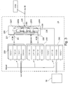
- FIG. 6 a block diagram of a master 2 of a further embodiment of the invention is shown schematically.
- That Bus system in Figure 6 also shows two slaves 81, 82 and a local bus 3.
- the master 2 has a transceiver circuit 30 for sending transmission data and receiving reception data via the local bus 3, for example by means of data packets.
- a reception memory area 210 is provided which can be used jointly by both channels 22, 23.
- both channels 22 and 23 have the receive memory area 210.
- the receive memory area 210 has a first buffer 211 and a second buffer 212.
- the buffers 211, 212 are characterized by different address spaces in the. Receive memory area 210 is formed.
- the address A is used for the Figure 6 to write, for example, 32-bit wide memory cells by data blocks D32 by means of a write pointer wp (English - write pointer) or to read them out by means of a read pointer rpf, rpl (English - read pointer).
- the transceiver circuit 30 is set up to write the received data of a data packet received via the local bus 3 into the second buffer 212 by means of the write pointer wp.
- the write pointer wp is controlled by a control circuit 245.
- the write pointer wp controlled by the control circuit 245 points to an address A of the second buffer 212 if previous received data of a previously received data packet is stored as valid received data in the first buffer 211.
- a determination circuit 340 of the transceiver 30 determines whether the received data or the received data packet is valid.
- the transceiver circuit 30 is set up to check the received data of the received data packet and to write the received data into the receive memory area 210.
- Writing the Received data can take place independently of the validity of the received data, with the validity of the received data being stored in the respective buffer 211, 212, for example by means of a flag. If the data stored in the buffer 211, 212 are invalid, they can be overwritten with the following data. Alternatively, it is possible to write the received data to a buffer 211, 212 of the receive memory area 210 only if the test result is positive and to discard it if it is invalid.
- the validity can be transmitted as validity value V from the determination circuit 310 of the transceiver circuit 30 to the control circuit 245 of the selection circuit 220.
- the determination of the validity value V may, for example, using a test value CRC32 (eng -. C yclic R edundancy C tail) or by a transmitted valid bits B.
- the validity bit B is shown, which can be transmitted in higher protocol layers and is used, for example, to ensure that one of the slaves 81, 82 uses the transmitted validity bit B to indicate to the master 2 that the received data sent by slave 81, 82 is invalid due to a slave's own error diagnosis, for example.
- the two possibilities described above are shown schematically with both values V, B. The determination of the validity is not limited to these two examples, so other types of validity can also be used.
- the transceiver circuit 30 is set up to write the received data of a data packet received via the local bus 3 into the first buffer 211 using the write pointer wp if previous received data of a previously received data packet is stored as valid received data in the second buffer 212. This ensures that at least the last valid received data is always in one of the two buffers 211, 212 of the receive memory area 210 and can be used.
- the control circuit 245 is also part of a selection circuit 220 which enables the data D32 stored in the memory area 210 to be selected via at least one read pointer rpl.
- the selection circuit 220 is part of at least one channel 22. In one embodiment of FIG Figure 6 is an output of the selection circuit 220 with the transceiver circuit 30 tied together.
- the selection circuit 220 has, through the read pointer, a first input 221 for selecting first data.
- the first data i.e. the default values
- the data packet reaches the transceiver circuit 30 of the master 2 via the slaves 81, 82, which can change the data in the data packet. If the master 2 receives data in the data packet, these are defined as receive data.
- the transceiver circuit 30 is set up to receive the data packet with a header and a data area via the bus 3 and to read the received data from the data area of the received data packet.
- the transceiver circuit 30 writes the received data into the second buffer 212, since the first buffer 211 contains valid data and the default values after the initialization.
- the selection circuit 220 has a second input in the form of the read pointer rpl, which enables a connection between the receive memory area 210 and the transceiver circuit 30.
- this is shown schematically in that the read pointer rpl is shown in dashed lines for another address A.
- the selection circuit 220 is set up to select the transmission data from the first data and the reception data written in the second buffer 212 of the reception memory area 210 and to output the transmission data to the transceiver circuit 30 for a new data packet to be transmitted.
- the transceiver circuit 30 is set up to send the new data packet to be sent with a header and a data area produce. If - as explained above - valid data is present in the second buffer 212 of the receive memory area 210, the control circuit 245 controls the read pointer rpl accordingly and the data D32 from the lowest address nA2 to the highest address hA2 of the second buffer 212 is transferred to the transceiver 30 copied.
- the connection between the receive memory area 210 and the input of the selection circuit 220 is designed for direct transmission of the received data from the second buffer 212.
- the selection circuit 220 does not need an external processor for this, but can control the direct transmission autonomously, for example by means of a copying process.
- the received data from the second buffer 212 are in the exemplary embodiment of Figure 6 entered unchanged as transmission data in the transceiver circuit 30.
- the transceiver circuit 30 is set up to write this transmission data into the data area of the new data packet to be transmitted when the new data packet to be transmitted is generated.
- the new data packet is in turn transmitted back to the transceiver circuit 30 of the master 2 by the slaves 81, 82.
- the transceiver circuit 30 again checks the validity of the received data in this new data packet.
- the receive data are written into the first buffer 211 of the receive memory area 210, since the valid receive data of the previous data packet was written in the second buffer 212 and is still present. If the new received data of the new data packet in the first buffer is also valid, the determination circuit 340 of the transceiver circuit 30 sends a validity bit B to the control circuit 245 of the selection circuit 220.
- the selection circuit 220 is set up to select the transmission data from the reception memory area 210, the reception data from that from the first buffer 211 or second buffer 212 that originate from the data packet last received and having valid reception data.
- the latest valid received data are now in the first buffer 211. Accordingly, the received data from the first buffer would be copied or shifted as send data into the transceiver circuit for a data packet to be generated subsequently. Accepted the received data in the first buffer 211 would be newer, but invalid, so the valid received data of the last data packet would be selected again with valid received data from the second buffer 212.
- the master 2 also has an interface circuit 60 to a higher-level bus 9 embodied, for example, as a field bus. Furthermore, the selection circuit 220 of the master 2 has a second read pointer rpf, which enables valid received data to be read out from the first buffer 211 or the second buffer 212. The received data of the last data packet with valid received data is transferred (for example copied) into the interface circuit 60 by means of the second read pointer rpf and transmitted via the field bus 9.
- a special channel 23 is assigned in the master 2 for transmission via the fieldbus 9. The channel 23 accordingly has the interface circuit 60 as its own hardware for the function of this channel 23.
Description
Die Erfindung betrifft einen Master eines Bussystems zur Prozesssteuerung. Das Bussystem weist weiterhin zumindest einen Slave und einen Bus auf.The invention relates to a master of a bus system for process control. The bus system also has at least one slave and one bus.
Aus der
Die
Der vorliegenden Erfindung liegt die Aufgabe zu Grunde, einen Master eines Bussystems anzugeben, der die Flexibilität der Kommunikation innerhalb des Bussystems möglichst erweitert.The present invention is based on the object of specifying a master of a bus system which expands the flexibility of communication within the bus system as much as possible.
Diese Aufgabe wird durch einen Master eines Bussystems mit den Merkmalen des Anspruchs 1 gelöst. Vorteilhafte Weiterbildungen der Erfindung sind in den abhängigen Ansprüchen angegeben.This object is achieved by a master of a bus system with the features of
Demzufolge ist ein Master eines Bussystems zur Prozesssteuerung vorgesehen. Das Bussystem weist zusätzlich zum Master einen Slave und einen Bus, der den Master und den Slave verbindet, auf. Unter einem Slave ist dabei zumindest ein Slave zu verstehen, so dass innerhalb des Bussystems einer oder mehrere Slaves mit dem Master verbunden sind.Accordingly, a master of a bus system is provided for process control. In addition to the master, the bus system has a slave and a bus that connects the master and the slave. A slave is to be understood as meaning at least one slave, so that one or more slaves are connected to the master within the bus system.
Der Master weist eine Transceiverschaltung zum Senden von Sendedaten und Empfangen von Empfangsdaten mittels Datenpakete auf. Die Sendedaten und die Empfangsdaten sind für die Prozesssteuerung vorgesehen. Die Sendedaten und die Empfangsdaten können auch als Prozessdaten bezeichnet werden. Vorzugsweise ist die Transceiverschaltung zum Senden und Empfangen der Datenpakete unmittelbar mit dem Bus verbunden.The master has a transceiver circuit for sending transmitted data and receiving received data by means of data packets. The send data and the receive data are intended for process control. The send data and the receive data can also be referred to as process data. The transceiver circuit is preferably used for transmitting and receiving Data packets directly connected to the bus.
Der Master hat einen Kanal, der zumindest einen Empfangs-Speicherbereich aufweist. Dabei ist unter einem Kanal zumindest ein Kanal zu verstehen, so dass der Master genau einen Kanal oder mehrere Kanäle, die jeweils einen Empfangs-Speicherbereich aufweisen können, hat. Der Kanal weist eine elektronische Schaltung auf, die mit der Transceiverschaltung verbunden ist. Die Schaltung des Kanals ist vorzugsweise für einen Kommunikationskanal über den Bus spezifiziert. Entsprechend können unterschiedliche Kanäle des Masters unterschiedliche Schaltungen aufweisen. Weiterhin kann der Kanal eine logische Verbindung zu einem oder mehreren Slaves über den Bus aufweisen. Der Empfangs-Speicherbereich ist vorteilhafterweise als Buffer ausgebildet. Beispielsweise ist der Empfangs-Speicherbereich mit der Funktion eines FIFOs ausgebildet. Der Empfangs-Speicherbereich ist beispielsweise durch eine Anzahl von Hardware-Buffern in einem ASIC (engl. - Application Specific Integrated Circuit / Anwendungsspezifischer Schaltkreis) oder ist beispielweise als Teil eines insbesondere flüchtigen Gesamtspeichers in einem FPGA (engl. - Field Programmable Gate Array) ausgebildet. Vorzugsweise ist die maximale Größe des Empfangs-Speicherbereichs fest eingestellt. Vorteilhafterweise ist der Kanal derart ausgebildet, dass im laufenden Betrieb auf den Empfangs-Speicherbereich kein Software-Programm zugreifen kann.The master has a channel which has at least one receive memory area. A channel is to be understood as at least one channel, so that the master has exactly one channel or several channels, each of which can have a receive memory area. The channel has electronic circuitry connected to the transceiver circuitry. The switching of the channel is preferably specified for a communication channel via the bus. Correspondingly, different channels of the master can have different circuits. Furthermore, the channel can have a logical connection to one or more slaves via the bus. The receive memory area is advantageously designed as a buffer. For example, the receive memory area is designed with the function of a FIFO. The receive memory area (engl. - A pplication S pecific I ntegrated C ircuit / application specific integrated circuit), for example, by a number of hardware buffers in an ASIC or, for example, English as part of a particular volatile total memory in an FPGA (-. Field Programmable Gate array). The maximum size of the receive memory area is preferably permanently set. The channel is advantageously designed in such a way that no software program can access the receive memory area during operation.
Die Transceiverschaltung ist eingerichtet, die Empfangsdaten eines über den Bus empfangenen Datenpakets in den Empfangs-Speicherbereich zu schreiben. Vorzugsweise ist die Transceiverschaltung eingerichtet, die Empfangsdaten basierend auf einer Struktur des Datenpakets aus dem Datenpaket zu entnehmen. Zusätzlich kann die Transceiverschaltung eine Anzahl weiterer Funktionen, wie beispielsweise die Prüfung des Datenpakets, aufweisen.The transceiver circuit is set up to write the received data of a data packet received via the bus into the receive memory area. The transceiver circuit is preferably set up to extract the received data from the data packet based on a structure of the data packet. In addition, the transceiver circuit can have a number of other functions, such as checking the data packet.
Der Kanal weist eine Selektionsschaltung auf. Dabei ist unter einer Selektionsschaltung zumindest eine Selektionsschaltung zu verstehen, so dass der Kanal genau eine Selektionsschaltung oder mehrere Selektionsschaltungen aufweisen kann. Ein Ausgang der Selektionsschaltung ist mit der Transceiverschaltung verbunden. Zwar ist es möglich, dass die Auswahl durch die Selektionsschaltung mittels Tabellen und Adressierung erfolgt, bevorzugt ist jedoch vorgesehen, dass die Selektionsschaltung durch Schaltelemente gebildet ist. Die Schaltelemente können beispielsweise einen Multiplexer bilden. Auch ist es möglich, die Selektionsschaltung durch eine Gatterlogik zu bilden, um die Sendedaten für das zu sendende Datenpaket auszuwählen.The channel has a selection circuit. A selection circuit is to be understood as at least one selection circuit, so that the channel can have precisely one selection circuit or a plurality of selection circuits. An output of the selection circuit is connected to the transceiver circuit. It is possible that the selection is made by the selection circuit using tables and addressing, which is preferred however, it is provided that the selection circuit is formed by switching elements. The switching elements can form a multiplexer, for example. It is also possible to form the selection circuit using gate logic in order to select the transmission data for the data packet to be transmitted.
Die Selektionsschaltung weist einen ersten Eingang zur Auswahl erster Daten auf. Die Selektionsschaltung weist zudem einen zweiten Eingang auf. Vorzugsweise sind der erste Eingang und der zweite Eingang digitale Eingänge mit derselben Bitbreite. Der zweite Eingang ist mit dem Empfangs-Speicherbereich verbunden. Der erste Eingang ist zur Bereitstellung der ersten Daten verbunden.The selection circuit has a first input for selecting first data. The selection circuit also has a second input. The first input and the second input are preferably digital inputs with the same bit width. The second input is connected to the receive memory area. The first input is connected to provide the first data.
Die Selektionsschaltung ist eingerichtet, die Sendedaten aus den ersten Daten und den in den Empfangs-Speicherbereich geschriebenen Empfangsdaten auszuwählen und die Sendedaten in die Transceiverschaltung für ein zu sendendes Datenpaket auszugeben. Die Auswahl umfasst dabei den ersten Fall, dass sämtliche erste Daten als Sendedaten durch die Selektionsschaltung ausgewählt werden. Die Auswahl umfasst auch den zweiten Fall, dass sämtliche Empfangsdaten als Sendedaten durch die Selektionsschaltung ausgewählt werden. Die Auswahl umfasst ebenfalls den dritten Fall, dass ein Teil der ersten Daten zusammen mit einem Teil der Empfangsdaten als Sendedaten durch die Selektionsschaltung ausgewählt werden.The selection circuit is set up to select the transmission data from the first data and the reception data written in the reception memory area and to output the transmission data into the transceiver circuit for a data packet to be transmitted. The selection includes the first case that all the first data are selected as transmission data by the selection circuit. The selection also includes the second case in which all of the received data are selected as transmitted data by the selection circuit. The selection also includes the third case in which part of the first data is selected together with part of the received data as transmission data by the selection circuit.
Durch diese Merkmale der Erfindung kann eine größere Flexibilität erzielt werden. Vorteile konkreter Ausführungsbeispiele der Erfindung sind in der Figurenbeschreibung erläutert.With these features of the invention, greater flexibility can be achieved. Advantages of specific exemplary embodiments of the invention are explained in the description of the figures.
Gemäß einer vorteilhaften Weiterbildung der Erfindung ist die Transceiverschaltung eingerichtet, ein Datenpaket mit einem Kopf und einem Datenbereich über den Bus zu empfangen und die Empfangsdaten aus dem Datenbereich des empfangenen Datenpakets zu lesen. Zum Empfangen des Datenpakets wird beispielsweise ein über den Bus an die Transceiverschaltung eingehendes Signal abgetastet. Zum Lesen der Empfangsdaten aus dem Datenbereich des empfangenen Datenpakets werden beispielsweise die Empfangsdaten innerhalb des Datenpakets - beispielweise anhand der Position innerhalb des Datenpakets - ermittelt.According to an advantageous development of the invention, the transceiver circuit is set up to receive a data packet with a header and a data area via the bus and to read the received data from the data area of the received data packet. To receive the data packet, for example, a signal arriving at the transceiver circuit via the bus is sampled. To read the received data from the data area of the received data packet, for example, the received data within the data packet - for example based on the position within the data packet - determined.
Gemäß einer vorteilhaften Weiterbildung der Erfindung ist die Transceiverschaltung eingerichtet, ein zu sendendes Datenpaket mit einem Kopf und einem Datenbereich zu erzeugen. Zur Erzeugung wird vorteilhafterweise der Kopf neu gebildet und beispielweise in ein Senderegister geschrieben. An den neu gebildeten Kopf wird dann beispielweise der Datenbereich angehängt. Zusätzlich zu Kopf und Datenbereich kann das Datenpaket einen oder mehrere weitere Bereiche aufweisen, beispielweise einen Prüfwert CRC (engl. CRC - Cyclic Redundancy Check), dieser kann auch als Prüfsumme bezeichnet werden.According to an advantageous development of the invention, the transceiver circuit is set up to generate a data packet to be sent with a header and a data area. For generation, the head is advantageously newly formed and written, for example, into a transmission register. The data area, for example, is then appended to the newly created header. In addition to header and data area, the data packet may comprise one or more further regions, for example a check value CRC (CRC eng -. C yclic R edundancy C tail), it can also be called a checksum.
Gemäß einer vorteilhaften Weiterbildung der Erfindung ist die Verbindung zwischen dem Empfangs-Speicherbereich und dem zweiten Eingang zur direkten Übertragung der Empfangsdaten ausgebildet. Ein Softwareprogramm einer CPU ist zur direkten Übertragung nicht erforderlich. Beispielsweise ist die direkte Verbindung durch eine feste Verdrahtung oder durch einen Kopierer - z.B. einer State-Machine oder einem Speicherdirektzugriff (DMA)- realisiert.According to an advantageous development of the invention, the connection between the receive memory area and the second input is designed for direct transmission of the received data. A software program of a CPU is not required for direct transfer. For example, the direct connection is implemented using fixed wiring or a copier - e.g. a state machine or direct memory access (DMA).
Gemäß einer vorteilhaften Weiterbildung der Erfindung ist die Transceiverschaltung eingerichtet, mit Erzeugung des zu sendenden Datenpakets die Sendedaten in den Datenbereich des zu sendenden Datenpakets zu schreiben. Zum Schreiben können die Sendedaten beispielsweise nach der Erzeugung des Kopfes des Datenpakets im Datenbereich angehängt werden. Der Datenbereich kann auch als Payload bezeichnet werden.According to an advantageous development of the invention, the transceiver circuit is set up to write the transmission data into the data area of the data packet to be transmitted when the data packet to be transmitted is generated. For writing, the send data can be appended in the data area, for example after the header of the data packet has been generated. The data area can also be referred to as a payload.
Gemäß einer vorteilhaften Weiterbildung der Erfindung ist die Transceiverschaltung eingerichtet, die Empfangsdaten des empfangenen Datenpakets zu prüfen und die Empfangsdaten in den Empfangs-Speicherbereich zu schreiben. Bevorzugt ist die Transceiverschaltung eingerichtet, nur bei positivem Prüfungsergebnis die Empfangsdaten in den Empfangs-Speicherbereich zu schreiben. Zur Prüfung kann beispielweise ein mit dem Datenpaket übertragener Gültigkeitswert ausgewertet werden. Bevorzugt ist die Transceiverschaltung eingerichtet, die Empfangsdaten anhand eines Prüfwertes CRC zu prüfen. Der Prüfwert weist beispielweise 32-Bit-Koeffizienten auf.According to an advantageous development of the invention, the transceiver circuit is set up to check the received data of the received data packet and to write the received data into the receive memory area. The transceiver circuit is preferably set up to write the received data to the receive memory area only if the test result is positive. For example, a validity value transmitted with the data packet can be evaluated for checking. The transceiver circuit is preferably set up to check the received data using a check value CRC. The check value has, for example, 32-bit coefficients.
Gemäß einer vorteilhaften Weiterbildung der Erfindung weist der Empfangs-Speicherbereich mindestens eine Größe auf, um alle Empfangsdaten des empfangenen Datenpakets zeitgleich zu speichern. Vorteilhafterweise ist die Größe des Empfangs-Speicherbereichs manuell oder automatisch konfigurierbar.According to an advantageous development of the invention, the receive memory area has at least one size in order to store all of the received data of the received data packet at the same time. The size of the receive memory area can advantageously be configured manually or automatically.
Gemäß einer vorteilhaften Weiterbildung der Erfindung weist der Master einen ersten Buffer und einen zweiten Buffer zum Empfang der Empfangsdaten auf. Beispielsweise sind der erste Buffer und der zweite Buffer Teilbereiche des Empfangs-Speicherbereichs. Ein Buffer kann auch als Puffer bezeichnet werden. Der Buffer dient der temporären Zwischenspeicherung der Empfangsdaten.According to an advantageous development of the invention, the master has a first buffer and a second buffer for receiving the received data. For example, the first buffer and the second buffer are partial areas of the receive memory area. A buffer can also be referred to as a buffer. The buffer is used to temporarily store the received data.
Vorzugsweise ist die Transceiverschaltung eingerichtet, die Empfangsdaten in den zweiten Buffer zu schreiben, wenn vorhergehende Empfangsdaten eines vorhergehend empfangenen Datenpakets als gültige Empfangsdaten im ersten Buffer gespeichert sind.The transceiver circuit is preferably set up to write the received data in the second buffer when previous received data of a previously received data packet is stored as valid received data in the first buffer.
Vorzugsweise ist die Transceiverschaltung eingerichtet, die Empfangsdaten in den ersten Buffer zu schreiben, wenn vorhergehende Empfangsdaten eines vorhergehend empfangenen Datenpakets als gültige Empfangsdaten im zweiten Buffer gespeichert sind.The transceiver circuit is preferably set up to write the received data in the first buffer when previous received data of a previously received data packet is stored as valid received data in the second buffer.
Gemäß einer vorteilhaften Weiterbildung der Erfindung ist die Selektionsschaltung eingerichtet, zur Auswahl der für die Sendedaten aus dem Empfangs-Speicherbereich die Empfangsdaten aus demjenigen aus ersten Buffer oder zweiten Buffer auszuwählen, die aus dem zuletzt empfangenen und gültige Empfangsdaten aufweisenden Datenpaket stammen.According to an advantageous development of the invention, the selection circuit is set up to select the received data for the send data from the receive memory area from that from the first buffer or second buffer that originate from the data packet containing valid received data last received.
Gemäß einer vorteilhaften Weiterbildung der Erfindung weist der erste Buffer mindestens eine Größe auf, um alle Empfangsdaten des empfangenen Datenpakets zeitgleich zu speichern. Gemäß einer vorteilhaften Weiterbildung der Erfindung weist der zweite Buffer mindestens eine Größe auf, um alle Empfangsdaten des empfangenen Datenpakets zeitgleich zu speichern.According to an advantageous development of the invention, the first buffer has at least one size in order to store all the received data of the received data packet at the same time. According to an advantageous development of the invention, the second buffer has at least one size in order to store all the received data of the received data packet at the same time.
Gemäß einer vorteilhaften Weiterbildung ist die Transceiverschaltung eingerichtet, die Datenpakete für die Sendedaten und die Empfangsdaten zu erzeugen. Die Sendedaten und die Empfangsdaten sind vorzugsweise dabei Bestandteil der Prozesssteuerung. Demzufolge ist die Transceiverschaltung zur Generierung des Datenpakets mit einer vorgegebenen Datenpaketstruktur eingerichtet. Dabei werden sowohl die vom Master gesendeten Datenpakete als auch die vom Master empfangenen Datenpakete im Bussystem ausschließlich von der Transceiverschaltung des Masters erzeugt. Dabei gelangen die vom Master gesendeten Datenpakete über den Bus und das Slave oder mehrere Slaves wieder zum Master zurück. Vorteilhafterweise ist der Bus dabei als Ringbus ausgebildet. Vorzugsweise weist das erzeugte Datenpaket einen Kopf und einen Datenbereich für die Sendedaten bzw. Empfangsdaten auf.According to an advantageous development, the transceiver circuit is set up to send the data packets for the transmitted data and the received data produce. The transmitted data and the received data are preferably part of the process control. Accordingly, the transceiver circuit is set up to generate the data packet with a predetermined data packet structure. Both the data packets sent by the master and the data packets received by the master are generated in the bus system exclusively by the master's transceiver circuit. The data packets sent by the master are returned to the master via the bus and the slave or several slaves. The bus is advantageously designed as a ring bus. The data packet generated preferably has a header and a data area for the send data and receive data, respectively.
Gemäß einer vorteilhaften Weiterbildung ist die Transceiverschaltung eingerichtet, den Kanal zu den Sendedaten mittels einer Kennung zuzuordnen. Die Kennung wird hierzu in das Datenpaket mit den zugehörigen Sendedaten eingefügt. Vorteilhafterweise ist die Transceiverschaltung zudem eingerichtet, den Kanal zu den Empfangsdaten mittels der Kennung im Datenpaket zuzuordnen. Hierzu wird die Kennung aus dem empfangenen Datenpaket ausgelesen.According to an advantageous development, the transceiver circuit is set up to assign the channel to the transmission data by means of an identifier. For this purpose, the identifier is inserted into the data packet with the associated send data. The transceiver circuit is also advantageously set up to assign the channel to the received data by means of the identifier in the data packet. For this purpose, the identifier is read out from the received data packet.
Zwar ist möglich, dass die Transceiverschaltung eingerichtet ist, die Zuordnung mittels Adressierung durchzuführen, gemäß einer vorteilhaften Ausgestaltung weist die Transceiverschaltung jedoch für die Zuordnung eine Zuordnungsschaltung, beispielsweise mit einer Tabelle (LUT - engl. Look Up Table) auf. Beispielsweise ist jedem am Eingang der LUT anliegendem Kennwert der Kennung eine Verbindung zu einem Kanal (von mehreren Kanälen) zugeordnet.While it is possible that the transceiver circuit is arranged to perform the assignment by means of addressing, however, according to an advantageous embodiment, the transceiver circuit for assigning an allocation circuit, for example, with a table (LUT - Engl. L ook U p T able) to. For example, each characteristic value of the identifier present at the input of the LUT is assigned a connection to a channel (of several channels).
Gemäß einer vorteilhaften Weiterbildung weist die Transceiverschaltung eine erste Finite-State-Machine (Endlicher Automat) auf. Die Transceiverschaltung ist eingerichtet, das Datenpaket für die Prozesssteuerung mit der Kennung mittels der ersten Finite-State-Machine zu erzeugen. Vorzugsweise ist die erste Finite-State-Machine durch eine abgeschlossene, spezifische Hardwareschaltung gebildet. Dies ermöglicht, dass die erste Finite-State-Machine weitgehend unabhängig von und/oder parallel zu einem Programm auf einem Prozessor des Masters arbeitet.According to an advantageous development, the transceiver circuit has a first finite state machine (finite state machine). The transceiver circuit is set up to generate the data packet for process control with the identifier by means of the first finite state machine. The first finite state machine is preferably formed by a closed, specific hardware circuit. This enables the first finite state machine to work largely independently of and / or in parallel with a program on a processor of the master.
Gemäß einer vorteilhaften Weiterbildung weist die Transceiverschaltung eine zweite Finite-State-Machine auf. Die zweite Finite-State-Machine ist eingerichtet, die Empfangsdaten des empfangenen Datenpakets basierend auf der im empfangenen Datenpaket enthaltenen Kennung und der Zuordnung zum Kanal in den Empfangs-Speicherbereich des Kanals zu schreiben. Vorzugsweise ist die zweite Finite-State-Machine durch eine abgeschlossene, spezifische Hardwareschaltung gebildet. Dies ermöglicht, dass die zweite Finite-State-Machine weitgehend unabhängig von und/oder parallel zu einem Programm auf einem Prozessor des Masters arbeitet. Weiterhin sind die erste und zweite Finite-State-Machine vorzugsweise als getrennte Schaltungsteile des Transceivers ausgebildet.According to an advantageous development, the transceiver circuit has a second finite state machine. The second finite state machine is set up to write the received data of the received data packet based on the identifier contained in the received data packet and the assignment to the channel in the receive memory area of the channel. The second finite state machine is preferably formed by a closed, specific hardware circuit. This enables the second finite state machine to work largely independently of and / or in parallel with a program on a processor of the master. Furthermore, the first and second finite state machines are preferably designed as separate circuit parts of the transceiver.
Gemäß einer vorteilhaften Weiterbildung weist die Transceiverschaltung einen Steuereingang auf. Die Transceiverschaltung ist eingerichtet, das Datenpaket basierend auf einem Steuersignal am Steuereingang zu erzeugen. Vorzugsweise weist der Master eine Rahmengeneratorschaltung auf. Die Rahmengeneratorschaltung ist eingerichtet, einen Zyklusrahmen zu erzeugen und innerhalb des Zyklusrahmens Datenpakete zeitlich zu positionieren. Die Rahmengeneratorschaltung ist eingerichtet, für ein Datenpaket das Steuersignal zu erzeugen und am Steuereingang der Transceiverschaltung anzulegen.According to an advantageous development, the transceiver circuit has a control input. The transceiver circuit is set up to generate the data packet based on a control signal at the control input. The master preferably has a frame generator circuit. The frame generator circuit is set up to generate a cycle frame and to position data packets temporally within the cycle frame. The frame generator circuit is set up to generate the control signal for a data packet and to apply it to the control input of the transceiver circuit.
Gemäß einer vorteilhaften Weiterbildung weist der Kanal zur Speicherung der ersten Daten einen Sende-Speicherbereich auf. Vorteilhafterweise ist der Master eingerichtet, die ersten Daten als Sendedaten in den Sende-Speicherbereich zu schreiben. Beispielsweise weist der Master einen Prozessor und ein vom Prozessor durchgeführtes Programm auf, die zur Prozesssteuerung eingerichtet sind. Vorteilhafterweise sind der Prozessor und das Programm eingerichtet, die ersten Daten als Sendedaten in den Sende-Speicherbereich über eine Schnittstelle des Kanals zu schreiben.According to an advantageous development, the channel has a transmit memory area for storing the first data. The master is advantageously set up to write the first data as send data in the send memory area. For example, the master has a processor and a program executed by the processor, which are set up for process control. The processor and the program are advantageously set up to write the first data as send data in the send memory area via an interface of the channel.
Gemäß einer vorteilhaften Weiterbildung weist der Master eine Feldbus-Schnittstellenschaltung auf. Die Feldbus-Schnittstellenschaltung ist mit dem Sende-Speicherbereich des Kanals verbunden. Beispielsweise ist die Feldbus-Schnittstellenschaltung mit dem Sende-Speicherbereich über einen integrierten, chip-internen Parallelbus verbunden. Die Feldbus-Schnittstellenschaltung ist zum Eingeben von über einen Feldbus empfangenen Prozessdaten - als die ersten Daten - in den Sende-Speicherbereich eingerichtet. Beispielsweise können die Prozessdaten aus einem Feldbustelegramm entnommen werden und geändert oder unverändert als erste Daten in den Sende-Speicherbereich geschrieben werden.According to an advantageous development, the master has a fieldbus interface circuit. The fieldbus interface circuit is connected to the send memory area of the channel. For example, the fieldbus interface circuit is connected to the transmit memory area via an integrated, chip-internal parallel bus connected. The fieldbus interface circuit is set up for inputting process data received via a fieldbus - as the first data - into the transmit memory area. For example, the process data can be taken from a fieldbus telegram and changed or written unchanged as the first data in the send memory area.
Gemäß einer vorteilhaften Weiterbildung ist die Selektionsschaltung zur bitgranularen Auswahl eingerichtet. Mittels der Selektionsschaltung sind Sende-Bits der Sendedaten aus Bits der ersten Daten und Bits der Empfangsdaten bitweise zusammengesetzt. Vorteilhafterweise weist die Selektionsschaltung zur bitgranularen Auswahl für jedes Bit ein Umschaltelement auf, wobei jedes Umschaltelement wiederum durch ein Steuerbit steuerbar ist.According to an advantageous development, the selection circuit is set up for bit-granular selection. By means of the selection circuit, send bits of the send data are put together bit by bit from bits of the first data and bits of the received data. The selection circuit for bit-granular selection advantageously has a switchover element for each bit, each switchover element in turn being controllable by a control bit.
Gemäß einer vorteilhaften Weiterbildung weist der erste Eingang der Selektionsschaltung für die ersten Daten eine Bitbreite von mehreren Bits auf. Vorteilhafterweise weist die Selektionsschaltung für jedes der mehreren Bits ein Schaltelement auf. Vorteilhafterweise ist die Selektionsschaltung derart eingerichtet, dass die Schaltelemente unabhängig voneinander ansteuerbar sind.According to an advantageous development, the first input of the selection circuit for the first data has a bit width of several bits. The selection circuit advantageously has a switching element for each of the plurality of bits. The selection circuit is advantageously set up in such a way that the switching elements can be controlled independently of one another.
Gemäß einer vorteilhaften Weiterbildung weist der Kanal einen Steuer-Speicherbereich mit Steuerwerten zur Steuerung der Selektionsschaltung auf. Die Steuerwerte können dabei vorzugsweise bitgranular die Schaltelemente der Selektionsschaltung ansteuern, um die Bits der Sendedaten einzeln aus Bits der ersten Daten und Bits der Empfangsdaten zusammenzusetzen.According to an advantageous development, the channel has a control memory area with control values for controlling the selection circuit. The control values can preferably control the switching elements of the selection circuit on a bit-granular basis in order to individually assemble the bits of the transmitted data from bits of the first data and bits of the received data.
Gemäß einer anderen vorteilhaften Weiterbildung sind die ersten Daten des Kanals feste Daten. Beispielsweise ist es dabei möglich, dass die ersten Daten in einem Register einprogrammiert sind. Bevorzugt sind die festen Daten durch Anschlüsse an High-Potential und/oder Low-Potential gebildet. Die festen Daten liegen am ersten Eingang der Selektionsschaltung an. Beispielsweise weisen die Bits der ersten Daten alle Low-Potential auf.According to another advantageous development, the first data of the channel are fixed data. For example, it is possible here for the first data to be programmed into a register. The fixed data are preferably formed by connections to high potential and / or low potential. The fixed data are available at the first input of the selection circuit. For example, the bits of the first data all have low potential.
Gemäß einer vorteilhaften Weiterbildung weist der Empfangs-Speicherbereich einen Steuerausgang zur Ausgabe eines Steuersignals zur Steuerung der Selektionsschaltung auf. Der Steuerausgang ist hierzu mit einem Eingang der Selektionsschaltung verbunden. Der Empfangs-Speicherbereich ist eingerichtet, einen Wert des Steuersignals basierend auf dem Empfang der Empfangsdaten an den Eingang der Selektionsschaltung anzulegen. Vorteilhafterweise ist der Empfangs-Speicherbereich eingerichtet, den Wert des Steuersignals basierend auf einem als gültig erkannten Empfang zu setzen.According to an advantageous development, the receive memory area has a control output for outputting a control signal for controlling the Selection switching on. For this purpose, the control output is connected to an input of the selection circuit. The reception memory area is set up to apply a value of the control signal based on the reception of the reception data to the input of the selection circuit. The receive memory area is advantageously set up to set the value of the control signal based on a reception recognized as valid.
Gemäß einer vorteilhaften Weiterbildung weist der Master eine Mehrzahl von Kanälen auf. Vorteilhafterweise sind die Schaltungen von zumindest zwei Kanälen unterschiedlich ausgebildet. Vorteilhafterweise weist jeder der zwei Kanäle zumindest zwei unterschiedliche Merkmale der vorhergehend erläuterten Weiterbildungen auf.According to an advantageous development, the master has a plurality of channels. The circuits of at least two channels are advantageously designed differently. Advantageously, each of the two channels has at least two different features of the developments explained above.
Die Aufgabe wird weiterhin durch ein Verfahren mit den Merkmalen des Anspruchs 22 gelöst. Vorteilhafte Weiterbildungen sind Gegenstand von abhängigen Ansprüchen.The object is also achieved by a method having the features of
Demzufolge ist ein Verfahren zum Betrieb eines Bussystems zur Prozesssteuerung vorgesehen. Das Bussystem weist einen Master und einen Slave auf. Unter einem Slave ist dabei zumindest ein Slave zu verstehen, so dass der Master genau ein Slave oder mehrere Slaves aufweist.Accordingly, a method for operating a bus system for process control is provided. The bus system has a master and a slave. A slave is to be understood as at least one slave, so that the master has exactly one slave or several slaves.
Im Verfahren wird vom Master ein Datenpaket mit Sendedaten für die Prozesssteuerung erzeugt. Vorteilhafterweise werden zur Erzeugung des Datenpakets Teile des Datenpakets, wie beispielsweise ein Kopf und ein Nutzdatenbereich bestimmt und zwischengespeichert. Die Sendedaten sind dabei Daten, die vom Master zumindest an den Slave oder an mehrere Slaves des Bussystems gesendet werden.In the process, the master generates a data packet with send data for process control. In order to generate the data packet, parts of the data packet, such as a header and a useful data area, are advantageously determined and temporarily stored. The send data are data that are sent by the master at least to the slave or to several slaves of the bus system.
Vom Master werden die Sendedaten aus einem ausgewählten Kanal in einen Nutzdatenbereich des Datenpakets geschrieben. Beispielsweise weist der Kanal einen Sende-Speicherbereich auf, der die Sendedaten enthält. Vorzugsweise beginnt das Schreiben nach der Auswahl des Kanals, jedoch bevor das Senden des Datenpakets durch den Master beginnt.The master writes the send data from a selected channel into a user data area of the data packet. For example, the channel has a transmission memory area which contains the transmission data. Writing preferably begins after the channel has been selected, but before the master begins to send the data packet.
Vom Master wird eine zum ausgewählten Kanal zugehörige Kennung in das Datenpaket geschrieben. Dabei kann die Kennung in den Kopf oder in den Nutzdatenbereich des Datenpakets geschrieben werden. Die Kennung weist vorzugsweise einen Wert mit einer festen Anzahl von Bits, beispielsweise 4 Bits oder 8 Bits auf. Die Zugehörigkeit zwischen Kennung und Kanal kann beispielsweise durch eine Tabelle oder durch eine andere Zuordnungsvorschrift erfolgen.An identifier belonging to the selected channel is written into the data packet by the master. The identifier can be written in the header or in the user data area of the data packet. The identifier preferably has a value with a fixed number of bits, for example 4 bits or 8 bits. The association between the identifier and the channel can be made, for example, by means of a table or another assignment rule.
Vom Master wird das Datenpaket beinhaltend die Kennung und die Sendedaten an den Slave gesendet. Vorteilhafterweise wird das Datenpaket zu einem festgelegten Zeitpunkt innerhalb eines Zyklusrahmens gesendet.The master sends the data packet including the identifier and the send data to the slave. The data packet is advantageously sent at a specified point in time within a cycle frame.
Das an den Slave gesendete Datenpaket wird zurück an den Master übertragen. Zuvor kann der Slave das Datenpaket, insbesondere Daten im Nutzdatenbereich verändern. Hierdurch werden Daten vom Slave an den Master gerichtet.The data packet sent to the slave is transferred back to the master. The slave can change the data packet beforehand, in particular data in the user data area. This directs data from the slave to the master.
Nachfolgend wird das Datenpaket vom Master empfangen. Vom Master wird das empfangende Datenpaket basierend auf der Kennung dem ausgewählten Kanal zugeordnet. Hierzu wird die Kennung innerhalb des Datenpakets, beispielsweise an der Position innerhalb des Datenpakets, ermittelt. Die Kennung kann beispielsweise mittels einer Tabelle wiederum eindeutig dem Kanal zugeordnet werden. Es stimmen bei identischer Kennung der Kanal des gesendeten Datenpakets und der Kanal des empfangenen Datenpakets überein.The data packet is then received by the master. The master assigns the received data packet to the selected channel based on the identifier. For this purpose, the identifier is determined within the data packet, for example at the position within the data packet. The identifier can in turn be uniquely assigned to the channel, for example by means of a table. If the identifier is identical, the channel of the sent data packet and the channel of the received data packet match.
Empfangsdaten des empfangenden Datenpakets werden im ausgewählten Kanal gespeichert. Die im Kanal gespeicherten Empfangsdaten können nachfolgend weitergenutzt werden. Beispielsweise werden die Empfangsdaten durch den Master ausgewertet. Auch ist es möglich, die Empfangsdaten weiterzusenden, beispielsweise über einen an den Master angeschlossenen Feldbus.Received data of the receiving data packet is saved in the selected channel. The received data stored in the channel can then be used again. For example, the received data are evaluated by the master. It is also possible to forward the received data, for example via a fieldbus connected to the master.
Gemäß einer vorteilhaften Weiterbildung werden die zuvor erläuterten Verfahrensschritte in der genannten Reihenfolge ausgeführt.According to an advantageous development, the method steps explained above are carried out in the order mentioned.
Gemäß einer vorteilhaften Weiterbildung wird vom Master ein Kanal aus einer Menge von zumindest zwei unterschiedlichen Kanälen für unterschiedliche Sendedaten ausgewählt. Die Auswahl wird vorzugsweise durch eine weitere Steuerschaltung des Masters gesteuert.According to an advantageous development, the master creates a channel from a set of at least two different channels for different ones Send data selected. The selection is preferably controlled by a further control circuit of the master.
Gemäß einer vorteilhaften Weiterbildung wird zumindest ein Teil der im ausgewählten Kanal gespeicherten Empfangsdaten für ein zu sendendes Datenpaket in die Sendedaten geschrieben. Vorteilhafterweise wird der Teil der im ausgewählten Kanal gespeicherten Empfangsdaten durch den Master ausgewählt. Der Teil wird durch den Master dabei mit weiteren Daten zur Bildung der Sendedaten zusammengefügt. Gemäß einer vorteilhaften Weiterbildung wird der Teil in ein nachfolgend zu sendendes Datenpaket mit derselben Kennung geschrieben. Zwar ist es möglich, dass Datenpakete mit derselben Kennung unmittelbar aufeinander folgen, dennoch können auch Datenpakete mit unterschiedlicher Kennung aufeinander folgen.According to an advantageous development, at least some of the received data stored in the selected channel for a data packet to be sent is written into the send data. The part of the received data stored in the selected channel is advantageously selected by the master. The master combines the part with other data to form the send data. According to an advantageous development, the part is written into a data packet to be subsequently sent with the same identifier. Although it is possible that data packets with the same identifier follow one another directly, data packets with different identifiers can also follow one another.
Gemäß einer vorteilhaften Weiterbildung wird durch den Master eine Nicht-Teilnahme eines Slaves an einer Buskommunikation auf dem Bus ermittelt. Die Nicht-Teilnahme kann beispielsweise mittels eines Zählerwertes und/oder einer Abfrage bestimmt werden. Bevorzugt wird durch den Master der dem ermittelten Slave zugehörige Teil der Empfangsdaten in die Sendedaten des Kanals geschrieben. Dabei kann der zugehörige Teil der Empfangsdaten ohne Abbruch fortlaufend in die Sendedaten des Kanals geschrieben werden. Alternativ wird der zugehörige Teil der Empfangsdaten bis zu einer Abbruchbedingung in die Sendedaten des Kanals geschrieben.According to an advantageous development, the master determines that a slave does not participate in bus communication on the bus. The non-participation can be determined for example by means of a counter value and / or a query. The part of the received data belonging to the determined slave is preferably written into the send data of the channel by the master. The associated part of the receive data can be continuously written to the send data of the channel without being aborted. Alternatively, the associated part of the receive data is written into the send data of the channel until an abort condition is met.
Eine Abbruchbedingung kann beispielsweise eine Änderung der Konfiguration sein oder eine Abbruchbedingung ist durch die Wiederaufnahme der Teilnahme des Slaves an der Buskommunikation gegeben oder die Abbruchbedingung wird durch eine Software auf dem Prozessor des Masters erzeugt. Wird beispielsweise ein Slave vom Bus entkoppelt, "gezogen", fehlt der Teil der Daten dieses Slaves in den Empfangsdaten. Der Master kann den letzt gültigen Teil der Empfangsdaten dieses Slaves durch die Rückspeisung in die Sendedaten weiterverwenden. Dieser Teil stellt zwar veraltete, jedoch zum entsprechenden Zeitpunkt gültige Daten dar.A termination condition can be, for example, a change in the configuration or a termination condition is given by the resumption of participation of the slave in the bus communication or the termination condition is generated by software on the processor of the master. If, for example, a slave is decoupled from the bus, "pulled", the part of the data of this slave is missing in the received data. The master can continue to use the last valid part of the received data from this slave by feeding it back into the send data. This part represents outdated, but valid data at the relevant point in time.
Gemäß einer anderen vorteilhaften Weiterbildung werden die im ausgewählten Kanal gespeicherten Empfangsdaten für ein zu sendendes Datenpaket vollständig in die Sendedaten geschrieben. Hierdurch werden Daten innerhalb des Busses zirkuliert. Vorteilhafterweise nehmen zumindest zwei Slaves an der Kommunikation mittels der zirkulierenden Daten teil. Dabei erzeugt der Master für jede Zirkulation ein neues Datenpaket, wobei die Empfangsdaten des empfangenen Datenpakets vorzugsweise unverändert in die Sendedaten des nächsten Datenpakets übernommen werden. Hierdurch können Daten von einem beliebigen, am Bus angeschlossenen Slave zu einem anderen beliebigen am Bus angeschlossenen Slave in beliebiger Richtung übertragen werden. Vorzugsweise werden die Datenpakete der Zirkulation zyklisch übertragen.According to another advantageous development, the selected in Receive data stored in the channel for a data packet to be sent is completely written to the send data. This causes data to be circulated within the bus. At least two slaves advantageously take part in the communication by means of the circulating data. The master generates a new data packet for each circulation, with the received data of the received data packet preferably being adopted unchanged in the send data of the next data packet. This allows data to be transferred from any slave connected to the bus to any other slave connected to the bus in any direction. The data packets of the circulation are preferably transmitted cyclically.
Gemäß einer anderen vorteilhaften Weiterbildung werden die Sendedaten aus ersten Daten und den in den Empfangs-Speicherbereich geschriebenen Empfangsdaten mittels einer Selektionsschaltung des Masters ausgewählt. Dabei ist ein Eingang der Selektionsschaltung mit einem Empfangs-Speicherbereich des ausgewählten Kanals verbunden. Ein Ausgang der Selektionsschaltung ist mit der Transceiverschaltung verbunden, so dass die Sendedaten in ein zu sendendes Datenpaket ausgegeben werden. Vorteilhafterweise wird die Selektionsschaltung durch ein Steuersignal gesteuert.According to another advantageous development, the transmission data are selected from the first data and the reception data written in the reception memory area by means of a selection circuit of the master. One input of the selection circuit is connected to a receive memory area of the selected channel. An output of the selection circuit is connected to the transceiver circuit so that the transmission data are output in a data packet to be transmitted. The selection circuit is advantageously controlled by a control signal.
Die Aufgabe wird weiterhin durch ein Bussystem mit den Merkmalen des Anspruchs 26 gelöst. Vorteilhafte Weiterbildungen sind in der Beschreibung enthalten.The object is also achieved by a bus system with the features of claim 26. Advantageous developments are contained in the description.
Demzufolge ist ein Bussystem zur Prozesssteuerung mit einem Master und einem Slave vorgesehen.Accordingly, a bus system for process control with a master and a slave is provided.
Der Master ist eingerichtet, ein Datenpaket mit Sendedaten für die Prozesssteuerung zu erzeugen.The master is set up to generate a data packet with send data for process control.
Der Master ist eingerichtet, die Sendedaten aus einem ausgewählten Kanal in einen Nutzdatenbereich des Datenpakets zu schreiben.The master is set up to write the send data from a selected channel into a user data area of the data packet.
Jeder Kanal weist jeweils einen zugehörigen Speicherbereich für seine Sendedaten auf.Each channel has an associated memory area for its transmission data.
Der Master ist eingerichtet, eine zum ausgewählten Kanal zugehörige Kennung in das Datenpaket zu schreiben.The master is set up to write an identifier belonging to the selected channel into the data packet.
Der Master ist eingerichtet, das Datenpaket beinhaltend die Kennung und die Sendedaten an den Slave zu senden.The master is set up to send the data packet containing the identifier and the send data to the slave.
Der Slave ist eingerichtet, das Datenpaket zu empfangen. Der Slave ist eingerichtet, basierend der Kennung zumindest einen Teil der Sendedaten zu lesen und/oder zumindest einen Teil Empfangsdaten zu schreiben. Der Slave ist eingerichtet, das Datenpaket zurück an den Master zu senden.The slave is set up to receive the data packet. The slave is set up to read at least part of the transmitted data and / or to write at least part of the received data based on the identifier. The slave is set up to send the data packet back to the master.
Der Master ist eingerichtet, das Datenpaket zu empfangen.The master is set up to receive the data packet.
Der Master ist eingerichtet, das empfangene Datenpaket basierend auf der Kennung dem ausgewählten Kanal zuzuordnen.The master is set up to assign the received data packet to the selected channel based on the identifier.
Der Master ist eingerichtet, die Empfangsdaten des empfangenen Datenpakets im ausgewählten Kanal zu speichern.The master is set up to save the received data of the received data packet in the selected channel.
Unter einem Slave ist genau ein Slave oder mehrere Slaves zu verstehen. In einem sehr kleinen Bussystem kann ein Master mit einem einzigen Slave verbunden sein. In einem gängigen Bussystem sind häufig mehrere Slaves über den Bus miteinander und mit dem Master verbunden. Beispielsweise sind der Master und die Slaves in einer Ringstruktur verbunden. Unter einem Datenpaket sind genau ein Datenpaket oder mehrere aufeinander folgende Datenpakete zu verstehen. So können beispielsweise eine Vielzahl von Datenpaketen nacheinander über den Bus des Bussystems übertragen werden.A slave is to be understood as exactly one slave or several slaves. In a very small bus system, a master can be connected to a single slave. In a common bus system, several slaves are often connected to one another and to the master via the bus. For example, the master and the slaves are connected in a ring structure. A data packet is understood to mean exactly one data packet or several consecutive data packets. For example, a large number of data packets can be transmitted one after the other via the bus of the bus system.
Die Erfindung ist dabei nicht auf die zuvor erläuterten Weiterbildungen begrenzt. So können die Weiterbildungen miteinander kombiniert werden. Vorteilhafte Ausgestaltungen der Erfindung sind in der Figurenbeschreibung erläutert.The invention is not limited to the developments explained above. In this way, the training courses can be combined with one another. Advantageous embodiments of the invention are explained in the description of the figures.
Dabei zeigen in unterschiedlichen Ausführungsbeispielen:
- Fig. 1
- einen schematischen Blockschaltplan eines Bussystems;
- Fig. 2
- einen schematischen Blockschaltplan eines Masters eines Bussystems;
- Fig. 3
- einen schematischen Blockschaltplan eines Kanals eines Masters;
- Fig. 4
- einen schematischen Blockschaltplan eines weiteren Kanals eines Masters; und
- Fig. 5
- eine schematische Darstellung von Datenpaketen in einem Bussystem; und
- Fig. 6
- einen schematischen Blockschaltplan eines Masters.
- Fig. 1
- a schematic block diagram of a bus system;
- Fig. 2
- a schematic block diagram of a master of a bus system;
- Fig. 3
- a schematic block diagram of a channel of a master;
- Fig. 4
- a schematic block diagram of a further channel of a master; and
- Fig. 5
- a schematic representation of data packets in a bus system; and
- Fig. 6
- a schematic block diagram of a master.
Die in
Zur Steuerung des Prozesses der Automatisierungsanlage ist die SPS 10 mit Automatisierungsgeräten verbunden. Um den Verdrahtungsaufwand gering zu halten werden für diese Verbindungen Bussysteme verwendet. In dem in
Der übergeordnete Bus 9 ist in dem hier gezeigten Ausführungsbeispiel der
Der Bus 3 ist vorteilhafterweise derart ausgebildet, dass ein vom Master 2 gesendetes Datenpaket durch alle mit dem Bus 3 verbundenen Slaves 81, 82 und an den Master 3 zurück übertragen wird. Dabei empfängt ein Slave 82 von seinem vorgelagerten Slave 81 immer nur einen Teil des Datenpakets. Nach einer Zeitspanne in der die in diesem Teil enthaltenen Daten vom Slave 81 verarbeitet werden können, wird der Teil an den nachgelagerten Slave 82 weitergeleitet und gleichzeitig wird von dem Master 2 ein neuer Teil des Datenpakets empfangen. Auf diese Weise passieren alle Teile des Datenpakets sequentiell alle Slaves 81, 82. Der Bus 3 ist vorteilhafterweise in einer ringförmigen Struktur ausgebildet. Derartige Lokalbusse können auch als Ringbus bezeichnet werden. Der Bus kann alternativ auch strangförmig oder sternförmig oder aus einer Kombination oder Mischform der zuvor genannten ausgebildet sein. Das Senden und Empfangen der Datenpakete wird dabei über die zweite Schnittstelle des Masters 3 bewerkstelligt. In dem hier gezeigten Ausführungsbeispiel weist die zweite Schnittstelle eine Abwärts- und eine Aufwärtsverbindung auf.The
Die Datensenderichtung im Ringbus 3 ist mit Pfeilen in dem in
Zur leichten Erfassung sind in dem Ausführungsbeispiel der
Der FBC 60 und der Prozessor 50 sind über einen Parallelbus 55 mit einer Datenverwaltungseinheit 70 und einem Kanal 21 verbunden. Der Parallelbus 55 ist beispielsweise ein 32-bit breiter Parallelbus. Die Verbindung 55 kann alternativ auch jede andere Verbindung sein, die einen Datentransfer zwischen den Einheiten erlaubt. Im Ausführungsbeispiel der
Die Datenverwaltungseinheit 70 ist eingerichtet, Daten in den Kanal 21 zu transferieren, um die Daten auf den Ringbus 3 in zumindest einem Datenpaket zu senden. Die Daten können dabei Prozessdaten sein, die über den Feldbus 9 in Feldbustelegrammen vom FBC 60 empfangen wurden. Alternativ könnten die Daten auch Prozessdaten sein, die vom Prozessor 50 erzeugt wurden.The
Der Master 2 weist eine Transceiverschaltung 30 auf, die eingerichtet ist, buskonforme Datenpakete zur Datenübertragung auf dem Bus 3 zu erzeugen und die von Kanal 21 erhaltenen Daten in das entsprechende Datenpaket einzufügen. Weiterhin ist die Transceiverschaltung 30 eingerichtet, über den Bus 3 zurückgesendete Datenpakete zu empfangen. In den empfangenden Datenpaketen enthaltene Daten werden durch die Transceiverschaltung 30 in den Kanal 21 geschrieben. Vom Kanal 21 können diese Daten über den Parallelbus 55 mittels der Datenverwaltungseinheit 70 dem FBC 60 und/oder dem Prozessor 50 zur weiteren Verarbeitung eingegeben werden.The
Der Master 2 weist zudem eine Steuerschaltung 40 zur Steuerung der Transceiverschaltung 30 auf. Die Steuerung erfolgt dabei parallel zu einem Programmablauf im Prozessor 50 und ist vom Prozessor 50 weitgehend unabhängig. Die Steuerschaltung 40 kann auch als Zyklusrahmengenerator bezeichnet werden, wobei die Steuerschaltung 40 die Transceiverschaltung 30 für die Erzeugung eines Zyklusrahmens ansteuert. Weiterhin ist die Steuerschaltung 40 eingerichtet, die Transceiverschaltung 30 zur Erzeugung eines Datenpakets anzusteuern. Die Transceiverschaltung 30 startet das Senden eines Datenpakets, wenn von der Steuerschaltung 40 das Steuersignal St über die Verbindung 41 an die Transceiverschaltung 30 angelegt wird. Beispielsweise werden mittels des Steuersignals ST ein Startpuls, eine Kennung ILI und die Länge des Datenpakets an die Transceiverschaltung 30 übertragen. Die Kennung ILI kann auch als Index bezeichnet werden. Nach dem Senden des Datenpakets informiert die Transceiverschaltung 30 die Steuerschaltung 40 über das Ende mittels eines Bestätigungssignals DN via die Verbindung 42.The
Schaltungen 21, 30, 40, 60, 70 des Masters 2 sind vorzugsweise auf einem Halbleiterchip 75 implementiert. Der Halbleiterchip kann beispielsweise als ASIC oder FPGA ausgebildet sein. Vorzugsweise sind die Schaltungen 21, 30, 40, 60, 70 vom Prozessor 50 getrennt, so dass zumindest die Transceiverschaltung 30 und der Kanal 21 unabhängig von einem Programmablauf auf dem Prozessor 50 betrieben werden können.
In
Das von der Transceiverschaltung 30 gesendete Datenpaket P enthält Sendedaten TD. Das von der Transceiverschaltung 30 empfangene Datenpaket P' enthält Empfangsdaten RD. Daten im Datenpaket P können von den Slaves 81, 82 verändert werden. Entsprechend sind die Sendedaten TD und die Empfangsdaten RD gleich oder unterschiedlich. Beide, Sendedaten TD und Empfangsdaten RD können für die Prozesssteuerung erforderlich sein. Die Transceiverschaltung 30 ist eingerichtet, das Datenpaket P' mit einem Kopf und einem Datenbereich über den Bus 3 zu empfangen und die Empfangsdaten RD aus dem Datenbereich PL des empfangenen Datenpakets P' zu lesen.The data packet P transmitted by the
Der Master 2 weist einen Kanal 21 auf, der mit der Transceiverschaltung 30 verbunden ist. Im Ausführungsbeispiel der
Im Ausführungsbeispiel der
Die Transceiverschaltung 30 ist eingerichtet, die Empfangsdaten RD des über den Bus 3 empfangenen Datenpakets P' in den Empfangs-Speicherbereich 210 des zugehörigen Kanals 21, 22, 23 zu schreiben. Mit jedem Kanal 21, 22, 23 kann ein anderes Datenpaket P gesendet werden. Dazu ist im Ausführungsbeispiel der
Die Slaves 81, 82 sind eingerichtet, die unterschiedlichen Datenpakete zu unterscheiden. Im Ausführungsbeispiel der
Der Master 2 ist eingerichtet, das empfangene Datenpaket P' basierend auf der Kennung dem ausgewählten Kanal 21, 22, 23 wieder zuzuordnen und die Empfangsdaten RD des empfangenen Datenpakets P' im ausgewählten Kanal 21, 22, 23 zu speichern. Ein Kanal 21, 22, 23 im Sinne des Ausführungsbeispiels der
Der Kanal 21 des Masters 2 im Ausführungsbeispiel der
Der Kanal 21 des Masters 2 weist im Ausführungsbeispiel der
Im Ausführungsbeispiel der
Im Ausführungsbeispiel der
Die Empfangsdaten RD können im Empfangs-Speicherbereich 210 durch die Selektionsschaltung 220 ausgewählt werden. Im Ausführungsbeispiel der
Im Ausführungsbeispiel der
Die Slaves 81, 82 im Ausführungsbeispiel der
In
Die ersten Daten D1 im Sende-Speicherbereich 230 sind beispielsweise Prozessdaten, die von einem Feldbus stammen. Entsprechend ist im Ausführungsbeispiel der
Im Ausführungsbeispiel der
In dem Ausführungsbeispiel der
Gemäß dem Ausführungsbeispiel der
In einem folgenden Schritt wird durch die Transceiverschaltung 30 des Masters 2 das Datenpaket P beinhaltend die Kennung ILI und die Sendedaten TD an den Slave 81, 82 gesendet. Hat das Datenpaket P alle Slaves 81, 82 passiert, wird das an den Slave 81, 82 gesendete Datenpaket P zurück an den Master 2 übertragen und von der Transceiverschaltung 30 wird das Datenpaket P' empfangen. In einem folgenden Schritt wird durch die Transceiverschaltung 30 des Masters 2 das empfangende Datenpaket P' basierend auf der Kennung ILI dem ausgewählten Kanal 21 zugeordnet. Dabei werden durch die Transceiverschaltung 30 die Empfangsdaten RD des empfangenden Datenpakets P' im ausgewählten Kanal 21 gespeichert.In a following step, the
Vorteilhafterweise ist der Master 2 eingerichtet eine Nicht-Teilnahme eines Slaves z.B. 81 an einer Buskommunikation auf dem Bus 3 zu ermitteln. Beispielsweise stimmt die Zahl gezählter Slaves nicht mit einer erwarteten Zahl von Slaves überein. Hierdurch wird besonders einfach durch den Master 2 eine Nicht-Teilnahme eines Slaves 81 an der Buskommunikation auf dem Bus 3 ermittelt. Diese Auswertung kann beispielsweise durch den Prozessor 50 erfolgen. Durch Abfragen über den Bus 3 kann herausgefunden werden, dass genau der Slave 81 nicht mehr an der Buskommunikation teilnimmt. In einem folgenden Schritt wird durch den Master 2 ein dem ermittelten Slave 81 zugehöriger Teil der Empfangsdaten RD in die Sendedaten TD des Kanals 21 geschrieben. Hierzu schreibt der Prozessor 50 die entsprechenden Steuerwerte in den Steuer-Speicherbereich 240. Dabei werden die zuletzt gültig von dem nicht mehr an der Kommunikation teilnehmenden Slave 81 empfangenen Daten aus den Empfangsdaten RD in die Sendedaten TD übernommen. Dies bewirkt, dass die vom Slave 81 als letztes gültig empfangenen Datenwerte eingefroren werden. Dies wird auch als "Halte-Letzten-Wert"-Funktion (engl. Hold Last Value) bezeichnet. Dies hat den Vorteil, dass nur gültige Werte verwendet werden, die zwar veraltet sind, jedoch keine Instabilität des Prozesses verursachen können. Hingegen können Standard-Default-Werte signifikant vom letzt gültigen Wert abweichen, wodurch signifikante Unstetigkeiten im System auftauchen können. Zudem weist die Lösung gemäß dem Ausführungsbeispiel der
In
Der Empfangs-Speicherbereich 210 weist einen Steuerausgang 219 zur Ausgabe eines Steuersignals NE zur Steuerung der Selektionsschaltung 220 auf. Dabei ist der Steuerausgang 219 des Empfangs-Speicherbereichs 210 mit einem Steuereingang 226 der Selektionsschaltung 220 verbunden. Der Empfangs-Speicherbereich 210 ist eingerichtet, einen Wert des Steuersignals NE basierend auf dem Empfang der Empfangsdaten RD an den Steuereingang 226 der Selektionsschaltung 220 anzulegen. Ist beispielsweise der Empfangs-Speicherbereich 210 leer, da noch kein gültiges Datenpaket P' empfangen wurde, so entspricht der Wert des Steuersignals NE einer Auswahl ausschließlich der festen ersten Daten D1 durch die Selektionsschaltung 220. Wurde hingegen bereits ein gültiges Datenpaket P' empfangen, so entspricht der Wert des Steuersignals NE einer Auswahl ausschließlich der Empfangsdaten RD durch die Selektionsschaltung 220. Durch die festen ersten Daten D1 kann dabei ein definierter Ausgangszustand erzielt werden, undefinierte Kommunikation wird vermieden.The
Durch die Ausgestaltung gemäß
In einem ersten Schritt wird die Transceiverschaltung 30 von der Steuerschaltung 40 angesteuert, um ein Datenpaket P zugehörig zum Kanal 22 zu erzeugen. Da der Empfangs-Speicherbereich 210 noch leer ist, werden durch die Selektionsschaltung 220 die festen ersten Daten D1 - z.B. ausschließlich Nullen - in den Nutzdatenbereich des Datenpakets P geschrieben. Dieses erste Datenpaket P wird über den Bus 3 zu den Slaves 81, 82 gesendet.In a first step, the
Sollen beispielsweise vom zweiten Slave 82 Daten an den ersten Slave 81 übertragen werden, so wird der zweite Slave 82 diese zu übertragenden Daten in das Datenpaket P schreiben.If, for example, data are to be transmitted from the
Danach wird durch die Transceiverschaltung das Datenpaket P' empfangen und die Empfangsdaten RD werden durch die Transceiverschaltung 30 in den Empfangs-Speicherbereich 210 geschrieben. Für ein nachfolgend zu sendendes Datenpaket P werden die im Empfangs-Speicherbereich 210 des ausgewählten Kanals 22 gespeicherten Empfangsdaten RD vollständig in die Sendedaten TD geschrieben. Dabei hat das Steuersignal NE einen Wert, der einem nicht-leeren Empfangs-Speicherbereich 210 zugehörig ist.The data packet P ′ is then received by the transceiver circuit and the received data RD are written into the receive
Auf diesem Wege gelangen die vom zweiten Slave 82 in das erste Datenpaket P geschriebenen Daten mittels des nachfolgenden zweiten Datenpakets P unverändert zum ersten Slave 81. Dem Fachmann ist klar, dass die Kommunikation auch in der umgekehrten Richtung vom ersten Slave 81 zum zweiten Slave 82 erfolgen kann.In this way, the data written by the
Zwar wird im Ausführungsbeispiel der
In einem Ausführungsbeispiel in
Im Ausführungsbeispiel der
Wie in den vorhergehenden Figuren erläutert ist die Transceiverschaltung 30 über die Ein-/Ausgänge 38, 39 mit einem oder mehreren Kanälen 21, 22, 23 verbunden.As explained in the preceding figures, the
Über den Eingang 31 erhält die Transceiverschaltung 30 einen Startpuls, eine Kennung ILI und die Länge des zu sendenden Datenpakets P. Die Transceiverschaltung ist eingerichtet, den Kanal 21, 22, 23 basierend auf der Kennung ILI auszuwählen. Dadurch kann die Transceiverschaltung 30 die Kennung ILI und den Kanal 21, 22, 23 mit Sendedaten TD einander zuordnen. Für die Zuordnung ist im Ausführungsbeispiel der
Die erste Finite-State-Machine 310 der Transceiverschaltung 30 ist eingerichtet, das Datenpaket P für die Prozesssteuerung mit den Sendedaten. TD und der Kennung ILI zu erzeugen. Die Transceiverschaltung 30 weist eine zweite Finite-State-Machine 320 auf und ist eingerichtet, die Empfangsdaten RD des empfangenen Datenpakets P' basierend auf der im empfangenen Datenpaket P' enthaltenen Kennung ILI und der Zuordnung zum Kanal 21, 22, 23 in den Empfangs-Speicherbereich 210 des zur Kennung ILI zugehörigen Kanals 21, 22, 23 zu schreiben. Für die Zuordnung mittels der Kennung ILI ist im Ausführungsbeispiel der
Die Datenbusteilnehmer 81, 82 sind mittels Instruktionslisten und der Kennung ILI eingerichtet, die Daten TD, RD im Datenpaket P auszuwerten. Die Kennung ILI kann auch als Index oder Instruktionslistenindex bezeichnet werden. Hierzu ist beispielsweise die Kennung ILI den Prozessdaten TD, RD im Datenpaket P vorangestellt. Erkennt der erste Slave 81 die Kennung ILI, beispielsweise an der Position der ILI innerhalb des Datenpakets P, legt der erste Slave die Daten TD in einem Empfangsregister 810 ab. Erkennt der zweite Slave 82 die Kennung ILI, beispielsweise an der Position der ILI innerhalb des Datenpakets P, legt der zweite Slave die Daten TD in seinem Empfangsregister 820 ab. Die Daten TD werden beim Ablegen beispielsweise kopiert und sind dann nach wie vor im Nutzdatenbereich PL des Datenpakets P enthalten. Entsprechend können die Slaves 81, 82 auch Daten in das Datenpaket P schreiben, indem bereits im Datenpaket P vorhandene Daten TD zu späteren Empfangsdaten RD geändert werden. Beispielsweise weist der Slave 81 einen Analogeingang (nicht dargestellt) auf, wobei digitale Eingangsdaten eines digitalisierten Analogsignals in den Nutzdatenbereich PL des Datenpakets P geschrieben werden. Hierdurch wird das Datenpaket P verändert und enthält nun die Daten des digitalisierten Analogsignals als Empfangsdaten RD für den Master 2.The
Wenn es sich bei dem Lokalbus 3 um einen Ringbus handelt, dann ist die Lokalbusschnittstelle des Masters in zwei Teile 33, 34 aufgeteilt. Dabei werden Daten TD über die Verbindung 33 in Abwärtsrichtung auf den Lokalbus 3 gesendet. Hierzu werden durch den Master 2 die Sendedaten TD aus einem ausgewählten Kanal 21, 22, 23 in einen Nutzdatenbereich PL des Datenpakets P geschrieben. Zudem wird durch den Master 2 eine zum ausgewählten Kanal 21, 22, 23 zugehörige Kennung ILI in das Datenpaket P geschrieben. Durch den Master 2 wird das Datenpaket P beinhaltend die Kennung ILI und die Sendedaten TD an den Slave 81, 82 gesendet. Anschließend werden vom Master 2 Daten RD des Datenpakets P' über die Verbindung 34 in Aufwärtsrichtung vom Lokalbus 3 empfangen. Dabei wird das an den Slave 81, 82 gesendete Datenpaket P zurück an den Master 2 übertragen. Durch den Master 2 wird das empfangende Datenpaket P' basierend auf der Kennung ILI dem ausgewählten Kanal 21, 22, 23 zugeordnet und die Empfangsdaten RD des empfangenden Datenpakets P' werden im ausgewählten Kanal 21, 22, 23 gespeichert. Die Gültigkeit der Empfangsdaten RD wird dabei beispielsweise anhand der CRC oder einem Valid-Bit bestimmt.If the
Dabei ist klar, dass auch bereits vor der Gültigkeitsanzeige Teile des von der Transceiverschaltung 30 erzeugten Datenpakets P auf den Lokalbus 3 gesendet werden können. Insbesondere, wenn die Teile des Datenpakets P die Slaves 81, 82 - wie in
Ein Zyklusrahmen kann dabei beispielsweise als ein wiederkehrendes (zyklisches) vorzugsweise äquidistantes Zeitintervall, in dem Daten auf dem Ringbus 3 übertragbar sind, definiert werden. Der Zyklusrahmen weist beispielsweise zumindest eine Startkennung und einen Zeitbereich zur Übertragung von Daten auf. Mehrere Startkennungen aufeinander folgender Zyklusrahmen sind dabei vorteilhafterweise in einem zeitlich äquidistanten Abstand zueinander. Der genannte Zeitbereich ist für die Übertragung der Daten TD, RD vorgesehen, die innerhalb des Zyklusrahmens in Form von Datenpaketen P, P' übertragen werden können. Die Startkennung und die Datenpakete P, P' werden über den Ringbus 3 übertragen und durchlaufen alle Datenbusteilnehmer, den Master 2 und die Slaves 81, 82. Vorteilhafterweise wird der Zyklusrahmen durch den Master 2 im Ringbus 3 initiiert. Die Startkennung ist separat, also als eigenständiges Symbol übertragbar oder vorteilhafterweise in einem Startdatenpaket enthalten.A cycle frame can be defined, for example, as a recurring (cyclical), preferably equidistant, time interval in which data can be transmitted on the
Innerhalb des Zeitbereichs des Zyklusrahmens werden keine, ein oder mehrere Datenpakete P, P' übertragen. Vorteilhafterweise werden in einem Zyklusrahmen Leerlauf-Daten (Idle-Data) eingefügt, insbesondere angrenzend an zumindest ein Datenpaket P, P'. Vorteilhafterweise bewirkt die Übertragung der Datenpakete P, P' und/oder der Leerlauf-Daten ein ununterbrochenes Signal auf dem Ringbus 3. Das Signal ermöglicht es den Slaves 81, 82 sich auf dieses zeitlich zu synchronisieren. Jedes Datenpaket P, P' wird von dem Master 2 in Abwärtsrichtung an den ersten Slave 81 des Ringbusses 3 gesendet. Dieser, empfängt einen ersten Teil des Datenpakets P über seine Schnittstelle. Der Slave 81 führt dann eine Verarbeitung des Teils aus, und leitet den Teil dann an den nächsten Slave 82 über seine Schnittstelle weiter, vorzugsweise gleichzeitig empfängt der erste Slave 81 einen zweiten Teil des Datenpakets P usw.No, one or more data packets P, P 'are transmitted within the time range of the cycle frame. Idle data are advantageously inserted in a cycle frame, in particular adjacent to at least one data packet P, P '. The transmission of the data packets P, P 'and / or the idle data advantageously brings about an uninterrupted signal on the
In
In einem Ausführungsbeispiel der
In einem Ausführungsbeispiel der
Die Transceiverschaltung 30 ist eingerichtet, die Empfangsdaten eines über den Lokalbus 3 empfangenen Datenpakets mittels des Schreib-Zeigers wp in den zweiten Buffer 212 zu schreiben. Dabei wird der Schreib-Zeiger wp durch eine Steuerschaltung 245 gesteuert. Der durch die Steuerschaltung 245 gesteuerte Schreib-Zeiger wp zeigt dabei auf eine Adresse A des zweiten Buffers 212, wenn vorhergehende Empfangsdaten eines vorhergehend empfangenen Datenpakets als gültige Empfangsdaten im ersten Buffer 211 gespeichert sind. Eine Ermittlungsschaltung 340 des Transceivers 30 bestimmt, ob die Empfangsdaten bzw. das empfangende Datenpaket gültig sind.The
Im Ausführungsbeispiel der
Die Transceiverschaltung 30 ist eingerichtet, die Empfangsdaten eines über den Lokalbus 3 empfangenen Datenpakets mittels des Schreib-Zeigers wp in den ersten Buffer 211 zu schreiben, wenn vorhergehende Empfangsdaten eines vorhergehend empfangenen Datenpakets als gültige Empfangsdaten im zweiten Buffer 212 gespeichert sind. So ist sichergestellt, dass zumindest immer die letzten gültigen Empfangsdaten in einem der beiden Buffer 211, 212 des Empfangs-Speicherbereichs 210 stehen und verwendet werden können.The
Die Steuerschaltung 245 ist zudem Bestandteil einer Selektionsschaltung 220, die über zumindest einen Lese-Pointer rpl eine Auswahl der im Speicherbereich 210 gespeicherten Daten D32 ermöglicht. Die Selektionsschaltung 220 ist dabei Bestandteil zumindest eines Kanals 22. In einem Ausführungsbeispiel der
Wird nun ein Datenpaket für die Zirkulation das erste Mal durch den Master 2 erzeugt, so werden als zu sendende Daten die ersten Daten, also die Default-Werte mittels des Lese-Zeigers rpl in das Datenpaket geschrieben und von der Transceiverschaltung 30 gesendet. Das Datenpaket gelangt über die Slaves 81, 82, die die Daten im Datenpaket ändern können, zurück an die Transceiverschaltung 30 des Masters 2. Empfängt der Master 2 Daten im Datenpaket, so sind diese als Empfangsdaten definiert. Die Transceiverschaltung 30 ist eingerichtet, das Datenpaket mit einem Kopf und einem Datenbereich über den Bus 3 zu empfangen und die Empfangsdaten aus dem Datenbereich des empfangenen Datenpakets zu lesen. Die Transceiverschaltung 30 schreibt die Empfangsdaten in den zweiten Buffer 212, da im ersten Buffer 211 gültige Daten, nach der Initialisierung die Default-Werte vorliegen.If a data packet for the circulation is now generated for the first time by the
In einem Ausführungsbeispiel der
Die Selektionsschaltung 220 ist eingerichtet, die Sendedaten aus den ersten Daten und den im zweiten Buffer 212 des Empfangs-Speicherbereichs 210 geschriebenen Empfangsdaten auszuwählen und die Sendedaten in die Transceiverschaltung 30 für ein neues, zu sendendes Datenpaket auszugeben. Im Ausführungsbeispiel der
Die Verbindung zwischen dem Empfangs-Speicherbereich 210 und dem Eingang der Selektionsschaltung 220 ist zur direkten Übertragung der Empfangsdaten aus dem zweiten Buffer 212 ausgebildet. Die Selektionsschaltung 220 benötigt hierzu keinen externen Prozessor, sondern kann die direkte Übertragung, beispielweise durch einen Kopiervorgang, autark steuern. Die Empfangsdaten aus dem zweiten Buffer 212 werden im Ausführungsbeispiel der
Das neue Datenpaket wird wiederum durch die Slaves 81, 82 zurück an die Transceiverschaltung 30 des Masters 2 übertragen. Die Transceiverschaltung 30 prüft erneut die Gültigkeit der Empfangsdaten in diesem neuen Datenpaket. Die Empfangsdaten werden in den ersten Buffer 211 des Empfangs-Speicherbereichs 210 geschrieben, da im zweiten Buffer 212 die gültigen Empfangsdaten des vorhergehenden Datenpakets geschrieben wurden und noch vorhanden sind. Sind auch die neuen Empfangsdaten des neuen Datenpakets im ersten Buffer gültig, sendet die Ermittlungsschaltung 340 der Transceiverschaltung 30 ein Gültigkeits-Bit B die Steuerschaltung 245 der Selektionsschaltung 220.The new data packet is in turn transmitted back to the
Die Selektionsschaltung 220 ist eingerichtet, zur Auswahl der Sendedaten aus dem Empfangs-Speicherbereich 210 die Empfangsdaten aus demjenigen aus ersten Buffer 211 oder zweiten Buffer 212 auszuwählen, die aus dem zuletzt empfangenen und gültige Empfangsdaten aufweisenden Datenpaket stammen. Im zuvor beschriebenen Fall liegen nun die neusten gültigen Empfangsdaten im ersten Buffer 211. Entsprechend würden für ein folgend zu erzeugendes Datenpaket die Empfangsdaten aus dem ersten Buffer als Sendedaten in die Transceiverschaltung kopiert oder verschoben. Angenommen die Empfangsdaten im ersten Buffer 211 wären zwar neuer, jedoch ungültig, so würden die gültigen Empfangsdaten des letzten Datenpakets mit gültigen Empfangsdaten aus dem zweiten Buffer 212 erneut selektiert.The
Im Ausführungsbeispiel der
- 11
- BussystemBus system
- 22
- Mastermaster
- 33
- Bus, RingbusBus, ring bus
- 99
- Feldbus, übergeordneter BusFieldbus, higher-level bus
- 1010
- SPS, LeitstationPLC, control station
- 21, 22, 2321, 22, 23
- Kanalchannel
- 3030th
- TransceiverschaltungTransceiver circuit
- 3131
- SteuereingangControl input
- 3232
- SignalausgangSignal output
- 3333
- Verbindung, AusgangConnection, exit
- 3434
- Verbindung, EingangConnection, input
- 3838
- Verbindung, AusgangConnection, exit
- 3939
- Verbindung, EingangConnection, input
- 4040
- Steuerschaltung, RahmengeneratorschaltungControl circuit, frame generator circuit
- 4141
- Verbindunglink
- 4242
- Verbindunglink
- 5050
- Prozessor, MikrocontrollerProcessor, microcontroller
- 5555
- Chip-interner ParallelbusOn-chip parallel bus
- 6060
- Feldbus-Schnittstellenschaltung, FBCFieldbus interface circuit, FBC
- 7070
- Datenverwaltungseinheit, DMA-ControllerData management unit, DMA controller
- 7575
- Halbleiterchip, Anwendungsspezifischer Schaltkreis, FPGASemiconductor chip, application-specific circuit, FPGA
- 81, 8281, 82
- SlaveSlave
- 210210
- Empfangs-SpeicherbereichReceive memory area
- 211, 212211, 212
- BufferBuffer
- 220220
- Selektionsschaltung, MUXSelection circuit, MUX
- 221, 222221, 222
- Eingangentry
- 225225
- Ausgangexit
- 226226
- SteuereingangControl input
- 230230
- Sende-SpeicherbereichSend memory area
- 240240
- Steuer-SpeicherbereichControl memory area
- 245245
- SteuerschaltungControl circuit
- 310, 320310, 320
- FSM, Finite-State-Machine, AutomatFSM, finite state machine, automat
- 330330
- Zuordnungseinheit, TabelleAllocation unit, table
- 340340
- ErmittlungsschaltungInvestigation circuit
- 810, 820810, 820
- Registerregister
- 2201, 2202, 2203, 22042201, 2202, 2203, 2204
- SchaltelementSwitching element
- CDCD
- SteuerdatenTax data
- CNTCNT
- ZählerwertCounter value
- CRCCRC
- PrüfwertTest value
- D1D1
- erste Datenfirst dates
- DNDN
- BestätigungssignalConfirmation signal
- HH
- Kopfhead
- NENE
- SteuersignalControl signal
- PLPL
- NutzdatenbereichUser data area
- IDEIDE
- DatenpaketkennungData packet identifier
- ILIILI
- KennungIdentifier
- P, P'P, P '
- DatenpaketData packet
- RDRD
- EmpfangsdatenReceive data
- STST
- SteuersignalControl signal
- TT
- TrailerTrailer
- TDTD
- SendedatenTransmission data
- LUTLUT
- Tabelle, ZuordnungstabelleTable, assignment table
- VV.
- GültigkeitswertValidity value
- BB.
- Gültigkeits-BitValidity bit
- D32D32
- Datendata
- AA.
- Adresseaddress
- nA1, nA2nA1, nA2
- niedrigste Adresselowest address
- hA1, hA2hA1, hA2
- höchste Adressehighest address
- wpwp
- Schreibzeiger, Write-PointerWrite pointer, write pointer
- rpf, rplrpf, rpl
- Lesezeiger, Read-PointerRead pointer, read pointer
Claims (26)
- Master (2) of a bus system (1) for process control with a slave (81, 82) and a bus (3),- having a transceiver circuit (30) for transmitting transmit data (TD) and for receiving receive data (RD) for the process control by means of data packets (P, P'),- having a channel (21, 22, 23) which has a receive storage area (210),- in which the transceiver circuit (30) is configured to write the receive data (RD) from a data packet (P') received via the bus (3) to the receive storage area (210),- in which the channel (21, 22, 23) has at least one selection circuit (220), wherein an output (225) of the selection circuit (220) is connected to the transceiver circuit (30),- in which the selection circuit (220) has a first input (221) for selecting first data (D1),- in which the selection circuit (220) has a second input (222), wherein the second input (222) is connected to the receive storage area (210), and- in which the selection circuit (220) is configured to select the transmit data (TD) from the receive data (RD) written to the receive storage area (210) and to output the transmit data (TD) to the transceiver circuit (30) for a data packet (P) to be transmitted via the bus (3) .
- Master (2) according to Claim 1,- in which the transceiver circuit (30) is configured to generate the data packets (P, P') for the transmit data (TD) and the receive data (RD), in particular having a header (H) and a data area (PL) for the transmit data (TD) or receive data (RD).
- Master (2) according to one of the preceding claims,- in which the transceiver circuit (30) is configured to receive a data packet (P') having a header (H) and a data area (PL) via the bus (3) and to read the receive data (RD) from the data area (PL) of the received data packet (P').
- Master (2) according to one of the preceding claims,- in which the transceiver circuit (30) is configured to generate a data packet (P) to be transmitted having a header (H) and a data area (PL) .
- Master (2) according to one of the preceding claims,- in which the connection between the receive storage area (210) and the second input (222) is designed to directly transmit the receive data (RD) .
- Master (2) according to one of the preceding claims,- in which the transceiver circuit (30) is configured, with the generation of the data packet (P) to be transmitted, to write the transmit data (TD) to the data area (PL) of the data packet (P) to be transmitted.
- Master (2) according to one of the preceding claims,- in which the transceiver circuit (30) is configured to check the receive data (RD) from the received data packet (P').
- Master (2) according to one of the preceding claims,- in which the receive storage area (210) has at least a size for storing all receive data (RD) from the received data packet (P') at the same time.
- Master (2) according to one of the preceding claims,- in which the receive storage area (210) has a first buffer (211) and a second buffer (212),- in which the transceiver circuit (30) is configured° to write the receive data (RD) to the second buffer (212) if previous receive data (RD) from a previously received data packet are stored as valid receive data (RD) in the first buffer (211),
or° to write the receive data (RD) to the first buffer (211) if previous receive data (RD) from a previously received data packet are stored as valid receive data (RD) in the second buffer (212) . - Master (2) according to Claim 9,- in which, in order to select the transmit data (TD) from the receive storage area (210), the selection circuit (220) is configured to select those receive data (RD) from that of the first buffer (211) or second buffer (212) which come from the last received data packet (P') having valid receive data (RD).
- Master (2) according to one of the preceding claims,- in which the transceiver circuit (30) is configured to assign the channel (21, 22, 23) to the transmit data (TD) and/or to the receive data (RD) by means of an identifier (ILI) in the data packet (P, P').
- Master (2) according to Claim 11,- in which the transceiver circuit (30) has a first finite state machine (310) and is configured to generate the data packet (P, P') for the process control with the identifier (ILI) by means of the first finite state machine (310).
- Master (2) according to either of Claims 11 and 12,- in which the transceiver circuit (30) has a second finite state machine (320) and is configured to write the receive data (RD) from the received data packet (P') to the receive storage area (210) of the channel (21, 22, 23) on the basis of the identifier (ILI) included in the received data packet (P') and the assignment to the channel (21, 22, 23).
- Master (2) according to one of the preceding claims,- in which the transceiver circuit (30) has a control input (31) and is configured to generate the data packet (P) on the basis of a control signal (St) at the control input (31).
- Master (2) according to one of the preceding claims,- in which the selection circuit (220) is configured to select the transmit data (TD) from the first data (D1) and the receive data (RD) written to the receive storage area (210).
- Master (2) according to Claim 15,- in which the channel (21, 23) has a transmit storage area (230) for storing the first data (D1) .
- Master (2) according to Claim 16,- having a field bus interface circuit (60), wherein the field bus interface circuit (60) is connected to the transmit storage area (230) of the channel (21, 23) for the purpose of inputting process data received via a field bus (9) to the transmit storage area (230) as the first data (D1) .
- Master (2) according to one of the preceding claims,- in which the selection circuit (220) is configured for bit-granular selection, wherein transmit bits of the transmit data (TD) are composed bit-by-bit from bits of the first data (D1) and bits of the receive data (RD) by means of the selection circuit (220).
- Master (2) according to one of the preceding claims,- in which the first input (221) of the selection circuit (220) has a bit width of a plurality of bits for the first data (D1), and- in which the selection circuit (220) has a switching element (2201, 2202, 2203, 2204) for each of the plurality of bits,- in which the selection circuit (220) is configured in such a manner that the switching elements (2201, 2202, 2203, 2204) can be controlled independently of one another.
- Master (2) according to one of the preceding claims,- in which the channel (21) has a control storage area (240) with control values for controlling the selection circuit (220).
- Master (2) according to one of the preceding claims,- in which the first data (D1) of the channel (22) are fixed data - in particular formed by connections at high potential and/or low potential - which are applied to the first input (221) of the selection circuit (220).
- Master (2) according to Claim 21,- in which the receive storage area (210) has a control output (219) for outputting a control signal (NE) for controlling the selection circuit (220) ,- in which the receive storage area (210) is configured to apply a value of the control signal (NE) to an input (226) of the selection circuit (220) on the basis of the reception of the receive data (RD).
- Method for operating a bus system (1) for process control with a master (2) and a slave (81, 82),- in which a data packet (P) containing transmit data (TD) for the process control is generated by the master (2),- in which the transmit data (TD) from a selected channel (21, 22, 23) are written to a payload area (PL) of the data packet (P) by the master (2),- in which an identifier (ILI) associated with the selected channel (21, 22, 23) is written to the data packet (P) by the master (2),- in which the data packet (P) comprising the identifier (ILI) and the transmit data (TD) is transmitted to the slave (81, 82) by the master (2),- in which the data packet (P) transmitted to the slave (81, 82) is transmitted back to the master (2) and the data packet (P') is received by the master (2),- in which the received data packet (P') is assigned to the selected channel (21, 22, 23) by the master (2) on the basis of the identifier (ILI),- in which receive data (RD) from the received data packet (P') are stored in the selected channel (21, 22, 23), and- in which at least some of the receive data (RD) stored in the selected channel (21, 22, 23) are written to the transmit data (TD) for a data packet (P) to be subsequently transmitted via the bus (3).
- Method according to Claim 23,- in which non-participation of a slave (81) in bus communication on the bus (3) is determined by the master (2),- in which some of the receive data (RD) associated with the determined slave (81) are written to the transmit data (TD) of the channel (21, 22, 23) by the master (2).
- Method according to Claim 23,- in which the receive data (RD) stored in the selected channel (21, 22, 23) are fully written to the transmit data (TD) for a data packet (P) to be subsequently transmitted.
- Bus system (1) for process control with a master (2) and a slave (81, 82),- in which the master (2) is configured to generate a data packet (P) containing transmit data (TD) for the process control,- in which the master (2) is configured to write the transmit data (TD) from a selected channel (21, 22, 23) to a payload area (PL) of the data packet (P),- in which each channel (21, 22, 23) respectively has an associated storage area (210, 230) for its transmit data (TD),- in which the master (2) is configured to write an identifier (ILI) associated with the selected channel (21, 22, 23) to the data packet (P),- in which the master (2) is configured to transmit the data packet (P) comprising the identifier (ILI) and the transmit data (TD) to the slave (81, 82),- in which the slave (81, 82) is configured to receive the data packet (P), to read at least some of the transmit data (TD) and/or to write at least some of the receive data on the basis of the identifier (ILI) and to transmit the data packet (P') back to the master (2),- in which the master (2) is configured to receive the data packet (P'),- in which the master (2) is configured to assign the received data packet (P') to the selected channel (21, 22, 23) on the basis of the identifier (ILI),- in which the master (2) is configured to store the receive data (RD) from the received data packet (P') in the selected channel (21, 22, 23), and- in which the master (2) is configured to write at least some of the receive data (RD) stored in the selected channel (21, 22, 23) to the transmit data (TD) for a data packet (P) to be subsequently transmitted via the bus (3).
Applications Claiming Priority (2)
| Application Number | Priority Date | Filing Date | Title |
|---|---|---|---|
| DE102017008186.7A DE102017008186B4 (en) | 2017-08-31 | 2017-08-31 | Master of a bus system |
| PCT/IB2018/000810 WO2019043447A1 (en) | 2017-08-31 | 2018-07-27 | Master of a bus system |
Publications (2)
| Publication Number | Publication Date |
|---|---|
| EP3676995A1 EP3676995A1 (en) | 2020-07-08 |
| EP3676995B1 true EP3676995B1 (en) | 2021-10-06 |
Family
ID=63364093
Family Applications (1)
| Application Number | Title | Priority Date | Filing Date |
|---|---|---|---|
| EP18759373.6A Active EP3676995B1 (en) | 2017-08-31 | 2018-07-27 | Master of a bus system |
Country Status (5)
| Country | Link |
|---|---|
| US (1) | US11296903B2 (en) |
| EP (1) | EP3676995B1 (en) |
| CN (1) | CN111052682B (en) |
| DE (1) | DE102017008186B4 (en) |
| WO (1) | WO2019043447A1 (en) |
Families Citing this family (1)
| Publication number | Priority date | Publication date | Assignee | Title |
|---|---|---|---|---|
| DE102021206498A1 (en) * | 2021-06-23 | 2022-12-29 | Siemens Healthcare Gmbh | Data transmission device, medical imaging device and method for transmission of data packets |
Family Cites Families (24)
| Publication number | Priority date | Publication date | Assignee | Title |
|---|---|---|---|---|
| US4636858A (en) * | 1984-10-30 | 1987-01-13 | The United States Of America As Represented By The Secretary Of The Air Force | Extracting digital data from a bus and multiplexing it with a video signal |
| ATE172038T1 (en) * | 1992-06-05 | 1998-10-15 | Compaq Computer Corp | DISK DRIVE CONTROL DEVICE WITH REWRITE CACHE MEMORY |
| JP3904244B2 (en) * | 1993-09-17 | 2007-04-11 | 株式会社ルネサステクノロジ | Single chip data processor |
| US6735683B2 (en) * | 1994-09-14 | 2004-05-11 | Hitachi, Ltd. | Single-chip microcomputer with hierarchical internal bus structure having data and address signal lines coupling CPU with other processing elements |
| CN1067195C (en) * | 1996-09-12 | 2001-06-13 | 中国科学院空间科学与应用研究中心 | High-speed multiplexer and its implementation |
| JPH10334037A (en) * | 1997-05-30 | 1998-12-18 | Sanyo Electric Co Ltd | Communication dma device |
| EP0901081B1 (en) * | 1997-07-08 | 2010-04-07 | Texas Instruments Inc. | A digital signal processor with peripheral devices and external interfaces |
| US6553432B1 (en) * | 1999-10-26 | 2003-04-22 | Dell Usa, L.P. | Method and system for selecting IDE devices |
| DE10006265B4 (en) * | 2000-02-12 | 2006-03-09 | Phoenix Contact Gmbh & Co. Kg | Device for controlling the data exchange in a communication subscriber |
| US20050198425A1 (en) * | 2004-03-05 | 2005-09-08 | Wang Liang-Yun | Combined optical storage and flash card reader using single ide or sata port and method thereof |
| US7209989B2 (en) * | 2004-09-29 | 2007-04-24 | Intel Corporation | Transfer acknowledgement mechanism for an MSL architecture |
| CN101098211B (en) * | 2005-06-30 | 2012-01-25 | 株式会社日立制作所 | Sending control device, receiving control device, and communication system |
| US7826411B2 (en) * | 2007-05-10 | 2010-11-02 | Broadcom Corporation | Cooperative transceiving between wireless interface devices of a host device with shared modules |
| US7881746B2 (en) * | 2007-05-10 | 2011-02-01 | Broadcom Corporation | Shared processing between wireless interface devices of a host device |
| DE102008019277B4 (en) * | 2008-04-16 | 2013-07-18 | Phoenix Contact Gmbh & Co. Kg | Data transfer device |
| US8230117B2 (en) * | 2009-04-09 | 2012-07-24 | International Business Machines Corporation | Techniques for write-after-write ordering in a coherency managed processor system that employs a command pipeline |
| KR101025674B1 (en) * | 2010-02-03 | 2011-03-30 | 엘에스산전 주식회사 | Device for switching a dual port ethernet |
| DE102010020446B4 (en) * | 2010-05-12 | 2012-12-06 | Wago Verwaltungsgesellschaft Mbh | Automation device and method for accelerated processing of selected process data |
| DE102011007437A1 (en) * | 2010-11-15 | 2012-05-16 | Continental Teves Ag & Co. Ohg | Method and circuit arrangement for data transmission between processor modules |
| EP2557464B1 (en) * | 2011-08-12 | 2015-07-29 | Siemens Aktiengesellschaft | Method for operating an automation system |
| US8880819B2 (en) * | 2011-12-13 | 2014-11-04 | Micron Technology, Inc. | Memory apparatuses, computer systems and methods for ordering memory responses |
| JP6058122B2 (en) * | 2013-03-25 | 2017-01-11 | 三菱電機株式会社 | Bus master, bus system, and bus control method |
| US10838908B2 (en) * | 2018-07-20 | 2020-11-17 | Xilinx, Inc. | Configurable network-on-chip for a programmable device |
| US10750377B1 (en) * | 2019-03-28 | 2020-08-18 | Integrated Device Technology, Inc. | Multi-mode control with fast-access lookup table implementation |
-
2017
- 2017-08-31 DE DE102017008186.7A patent/DE102017008186B4/en active Active
-
2018
- 2018-07-27 CN CN201880055128.4A patent/CN111052682B/en active Active
- 2018-07-27 WO PCT/IB2018/000810 patent/WO2019043447A1/en unknown
- 2018-07-27 EP EP18759373.6A patent/EP3676995B1/en active Active
-
2020
- 2020-02-28 US US16/805,411 patent/US11296903B2/en active Active
Also Published As
| Publication number | Publication date |
|---|---|
| US20200204398A1 (en) | 2020-06-25 |
| EP3676995A1 (en) | 2020-07-08 |
| CN111052682A (en) | 2020-04-21 |
| DE102017008186A1 (en) | 2019-02-28 |
| DE102017008186B4 (en) | 2022-12-15 |
| CN111052682B (en) | 2022-05-24 |
| WO2019043447A1 (en) | 2019-03-07 |
| US11296903B2 (en) | 2022-04-05 |
Similar Documents
| Publication | Publication Date | Title |
|---|---|---|
| DE3300261C2 (en) | ||
| DE102007004044B4 (en) | Method and system for optimized transmission of data between a control device and a plurality of field devices | |
| EP1787204B1 (en) | Message administrator and method for controlling access to data of the message memory of a communications component | |
| EP1456722A2 (en) | Data transmission method, serial bus system and switch-on unit for a passive station | |
| EP1502400B1 (en) | Method and system for transmitting data via switchable data networks | |
| EP3759871B1 (en) | Master-slave bus system and method for operating a bus system | |
| EP1776807A1 (en) | Method and device for accessing data of a message memory of a communication component | |
| DE102005048581B4 (en) | Subscriber interface between a FlexRay communication module and a FlexRay subscriber and method for transmitting messages via such an interface | |
| DE102017125086A1 (en) | Data transmission method and communication network | |
| WO2006015908A1 (en) | Method for storing messages in a message memory and corresponding message memory | |
| EP3685236A1 (en) | Circuit for coupling a field bus and a local bus | |
| EP3676995B1 (en) | Master of a bus system | |
| EP1133106B1 (en) | Device for controlling the data exchange in a communication terminal | |
| WO2004025493A1 (en) | Integrated circuit comprising multiplexers for switching between normal mode and test mode | |
| EP3072250B1 (en) | Communication device, communication system and method for the synchronised sending of messages | |
| EP1430670A1 (en) | Method for operating an isochronous cyclic communication system | |
| EP1430654A1 (en) | Method for creating a static address table and data network | |
| EP1371184B1 (en) | Electronic switching circuit and method for a communication interface with buffer storage | |
| DE102017002806B4 (en) | Coupler for an automation system | |
| DE10141187B4 (en) | Electronic circuit and method for a communication interface with buffering | |
| EP1371193B1 (en) | Elektronischer schaltkreis und verfahren fur eine kommunikationsschnittstelle mit cut-through pufferspeicher | |
| EP3824393A1 (en) | Circuit for a buffered transmission of data | |
| DE102018010209A1 (en) | Master-slave bus system and method for operating a bus system | |
| DE102017216991B4 (en) | Communication module and device for data transmission | |
| EP1430657B1 (en) | Method for creating a dynamic address table for a switching node in a data network and a method for transmitting a data message |
Legal Events
| Date | Code | Title | Description |
|---|---|---|---|
| STAA | Information on the status of an ep patent application or granted ep patent |
Free format text: STATUS: UNKNOWN |
|
| STAA | Information on the status of an ep patent application or granted ep patent |
Free format text: STATUS: THE INTERNATIONAL PUBLICATION HAS BEEN MADE |
|
| PUAI | Public reference made under article 153(3) epc to a published international application that has entered the european phase |
Free format text: ORIGINAL CODE: 0009012 |
|
| STAA | Information on the status of an ep patent application or granted ep patent |
Free format text: STATUS: REQUEST FOR EXAMINATION WAS MADE |
|
| 17P | Request for examination filed |
Effective date: 20200213 |
|
| AK | Designated contracting states |
Kind code of ref document: A1 Designated state(s): AL AT BE BG CH CY CZ DE DK EE ES FI FR GB GR HR HU IE IS IT LI LT LU LV MC MK MT NL NO PL PT RO RS SE SI SK SM TR |
|
| AX | Request for extension of the european patent |
Extension state: BA ME |
|
| DAV | Request for validation of the european patent (deleted) | ||
| DAX | Request for extension of the european patent (deleted) | ||
| GRAP | Despatch of communication of intention to grant a patent |
Free format text: ORIGINAL CODE: EPIDOSNIGR1 |
|
| STAA | Information on the status of an ep patent application or granted ep patent |
Free format text: STATUS: GRANT OF PATENT IS INTENDED |
|
| INTG | Intention to grant announced |
Effective date: 20210601 |
|
| GRAS | Grant fee paid |
Free format text: ORIGINAL CODE: EPIDOSNIGR3 |
|
| GRAA | (expected) grant |
Free format text: ORIGINAL CODE: 0009210 |
|
| STAA | Information on the status of an ep patent application or granted ep patent |
Free format text: STATUS: THE PATENT HAS BEEN GRANTED |
|
| AK | Designated contracting states |
Kind code of ref document: B1 Designated state(s): AL AT BE BG CH CY CZ DE DK EE ES FI FR GB GR HR HU IE IS IT LI LT LU LV MC MK MT NL NO PL PT RO RS SE SI SK SM TR |
|
| REG | Reference to a national code |
Ref country code: GB Ref legal event code: FG4D Free format text: NOT ENGLISH |
|
| REG | Reference to a national code |
Ref country code: CH Ref legal event code: EP Ref country code: AT Ref legal event code: REF Ref document number: 1437183 Country of ref document: AT Kind code of ref document: T Effective date: 20211015 |
|
| REG | Reference to a national code |
Ref country code: DE Ref legal event code: R096 Ref document number: 502018007378 Country of ref document: DE |
|
| REG | Reference to a national code |
Ref country code: IE Ref legal event code: FG4D Free format text: LANGUAGE OF EP DOCUMENT: GERMAN |
|
| REG | Reference to a national code |
Ref country code: LT Ref legal event code: MG9D |
|
| REG | Reference to a national code |
Ref country code: NL Ref legal event code: MP Effective date: 20211006 |
|
| PG25 | Lapsed in a contracting state [announced via postgrant information from national office to epo] |
Ref country code: RS Free format text: LAPSE BECAUSE OF FAILURE TO SUBMIT A TRANSLATION OF THE DESCRIPTION OR TO PAY THE FEE WITHIN THE PRESCRIBED TIME-LIMIT Effective date: 20211006 Ref country code: LT Free format text: LAPSE BECAUSE OF FAILURE TO SUBMIT A TRANSLATION OF THE DESCRIPTION OR TO PAY THE FEE WITHIN THE PRESCRIBED TIME-LIMIT Effective date: 20211006 Ref country code: FI Free format text: LAPSE BECAUSE OF FAILURE TO SUBMIT A TRANSLATION OF THE DESCRIPTION OR TO PAY THE FEE WITHIN THE PRESCRIBED TIME-LIMIT Effective date: 20211006 Ref country code: BG Free format text: LAPSE BECAUSE OF FAILURE TO SUBMIT A TRANSLATION OF THE DESCRIPTION OR TO PAY THE FEE WITHIN THE PRESCRIBED TIME-LIMIT Effective date: 20220106 |
|
| PG25 | Lapsed in a contracting state [announced via postgrant information from national office to epo] |
Ref country code: IS Free format text: LAPSE BECAUSE OF FAILURE TO SUBMIT A TRANSLATION OF THE DESCRIPTION OR TO PAY THE FEE WITHIN THE PRESCRIBED TIME-LIMIT Effective date: 20220206 Ref country code: SE Free format text: LAPSE BECAUSE OF FAILURE TO SUBMIT A TRANSLATION OF THE DESCRIPTION OR TO PAY THE FEE WITHIN THE PRESCRIBED TIME-LIMIT Effective date: 20211006 Ref country code: PT Free format text: LAPSE BECAUSE OF FAILURE TO SUBMIT A TRANSLATION OF THE DESCRIPTION OR TO PAY THE FEE WITHIN THE PRESCRIBED TIME-LIMIT Effective date: 20220207 Ref country code: PL Free format text: LAPSE BECAUSE OF FAILURE TO SUBMIT A TRANSLATION OF THE DESCRIPTION OR TO PAY THE FEE WITHIN THE PRESCRIBED TIME-LIMIT Effective date: 20211006 Ref country code: NO Free format text: LAPSE BECAUSE OF FAILURE TO SUBMIT A TRANSLATION OF THE DESCRIPTION OR TO PAY THE FEE WITHIN THE PRESCRIBED TIME-LIMIT Effective date: 20220106 Ref country code: NL Free format text: LAPSE BECAUSE OF FAILURE TO SUBMIT A TRANSLATION OF THE DESCRIPTION OR TO PAY THE FEE WITHIN THE PRESCRIBED TIME-LIMIT Effective date: 20211006 Ref country code: LV Free format text: LAPSE BECAUSE OF FAILURE TO SUBMIT A TRANSLATION OF THE DESCRIPTION OR TO PAY THE FEE WITHIN THE PRESCRIBED TIME-LIMIT Effective date: 20211006 Ref country code: HR Free format text: LAPSE BECAUSE OF FAILURE TO SUBMIT A TRANSLATION OF THE DESCRIPTION OR TO PAY THE FEE WITHIN THE PRESCRIBED TIME-LIMIT Effective date: 20211006 Ref country code: GR Free format text: LAPSE BECAUSE OF FAILURE TO SUBMIT A TRANSLATION OF THE DESCRIPTION OR TO PAY THE FEE WITHIN THE PRESCRIBED TIME-LIMIT Effective date: 20220107 Ref country code: ES Free format text: LAPSE BECAUSE OF FAILURE TO SUBMIT A TRANSLATION OF THE DESCRIPTION OR TO PAY THE FEE WITHIN THE PRESCRIBED TIME-LIMIT Effective date: 20211006 |
|
| REG | Reference to a national code |
Ref country code: DE Ref legal event code: R097 Ref document number: 502018007378 Country of ref document: DE |
|
| PG25 | Lapsed in a contracting state [announced via postgrant information from national office to epo] |
Ref country code: SM Free format text: LAPSE BECAUSE OF FAILURE TO SUBMIT A TRANSLATION OF THE DESCRIPTION OR TO PAY THE FEE WITHIN THE PRESCRIBED TIME-LIMIT Effective date: 20211006 Ref country code: SK Free format text: LAPSE BECAUSE OF FAILURE TO SUBMIT A TRANSLATION OF THE DESCRIPTION OR TO PAY THE FEE WITHIN THE PRESCRIBED TIME-LIMIT Effective date: 20211006 Ref country code: RO Free format text: LAPSE BECAUSE OF FAILURE TO SUBMIT A TRANSLATION OF THE DESCRIPTION OR TO PAY THE FEE WITHIN THE PRESCRIBED TIME-LIMIT Effective date: 20211006 Ref country code: EE Free format text: LAPSE BECAUSE OF FAILURE TO SUBMIT A TRANSLATION OF THE DESCRIPTION OR TO PAY THE FEE WITHIN THE PRESCRIBED TIME-LIMIT Effective date: 20211006 Ref country code: DK Free format text: LAPSE BECAUSE OF FAILURE TO SUBMIT A TRANSLATION OF THE DESCRIPTION OR TO PAY THE FEE WITHIN THE PRESCRIBED TIME-LIMIT Effective date: 20211006 Ref country code: CZ Free format text: LAPSE BECAUSE OF FAILURE TO SUBMIT A TRANSLATION OF THE DESCRIPTION OR TO PAY THE FEE WITHIN THE PRESCRIBED TIME-LIMIT Effective date: 20211006 |
|
| PLBE | No opposition filed within time limit |
Free format text: ORIGINAL CODE: 0009261 |
|
| STAA | Information on the status of an ep patent application or granted ep patent |
Free format text: STATUS: NO OPPOSITION FILED WITHIN TIME LIMIT |
|
| 26N | No opposition filed |
Effective date: 20220707 |
|
| PG25 | Lapsed in a contracting state [announced via postgrant information from national office to epo] |
Ref country code: AL Free format text: LAPSE BECAUSE OF FAILURE TO SUBMIT A TRANSLATION OF THE DESCRIPTION OR TO PAY THE FEE WITHIN THE PRESCRIBED TIME-LIMIT Effective date: 20211006 |
|
| PG25 | Lapsed in a contracting state [announced via postgrant information from national office to epo] |
Ref country code: SI Free format text: LAPSE BECAUSE OF FAILURE TO SUBMIT A TRANSLATION OF THE DESCRIPTION OR TO PAY THE FEE WITHIN THE PRESCRIBED TIME-LIMIT Effective date: 20211006 |
|
| PG25 | Lapsed in a contracting state [announced via postgrant information from national office to epo] |
Ref country code: MC Free format text: LAPSE BECAUSE OF FAILURE TO SUBMIT A TRANSLATION OF THE DESCRIPTION OR TO PAY THE FEE WITHIN THE PRESCRIBED TIME-LIMIT Effective date: 20211006 |
|
| GBPC | Gb: european patent ceased through non-payment of renewal fee |
Effective date: 20220727 |
|
| REG | Reference to a national code |
Ref country code: BE Ref legal event code: MM Effective date: 20220731 |
|
| PG25 | Lapsed in a contracting state [announced via postgrant information from national office to epo] |
Ref country code: LU Free format text: LAPSE BECAUSE OF NON-PAYMENT OF DUE FEES Effective date: 20220727 |
|
| PG25 | Lapsed in a contracting state [announced via postgrant information from national office to epo] |
Ref country code: GB Free format text: LAPSE BECAUSE OF NON-PAYMENT OF DUE FEES Effective date: 20220727 Ref country code: BE Free format text: LAPSE BECAUSE OF NON-PAYMENT OF DUE FEES Effective date: 20220731 |
|
| P01 | Opt-out of the competence of the unified patent court (upc) registered |
Effective date: 20230516 |
|
| PG25 | Lapsed in a contracting state [announced via postgrant information from national office to epo] |
Ref country code: IE Free format text: LAPSE BECAUSE OF NON-PAYMENT OF DUE FEES Effective date: 20220727 |
|
| PGFP | Annual fee paid to national office [announced via postgrant information from national office to epo] |
Ref country code: IT Payment date: 20230721 Year of fee payment: 6 Ref country code: CH Payment date: 20230801 Year of fee payment: 6 Ref country code: AT Payment date: 20230718 Year of fee payment: 6 |
|
| PGFP | Annual fee paid to national office [announced via postgrant information from national office to epo] |
Ref country code: FR Payment date: 20230725 Year of fee payment: 6 Ref country code: DE Payment date: 20230726 Year of fee payment: 6 |