EP3673348B1 - Data processing device, method and non-transitory machine-readable medium for detecting motion of the data processing device - Google Patents
Data processing device, method and non-transitory machine-readable medium for detecting motion of the data processing device Download PDFInfo
- Publication number
- EP3673348B1 EP3673348B1 EP18755269.0A EP18755269A EP3673348B1 EP 3673348 B1 EP3673348 B1 EP 3673348B1 EP 18755269 A EP18755269 A EP 18755269A EP 3673348 B1 EP3673348 B1 EP 3673348B1
- Authority
- EP
- European Patent Office
- Prior art keywords
- image
- data processing
- processing device
- marker
- captured
- Prior art date
- Legal status (The legal status is an assumption and is not a legal conclusion. Google has not performed a legal analysis and makes no representation as to the accuracy of the status listed.)
- Active
Links
- 230000033001 locomotion Effects 0.000 title claims description 104
- 238000012545 processing Methods 0.000 title claims description 76
- 238000000034 method Methods 0.000 title claims description 11
- 239000003550 marker Substances 0.000 claims description 88
- 230000004044 response Effects 0.000 claims description 16
- 230000009466 transformation Effects 0.000 claims description 13
- 238000003672 processing method Methods 0.000 claims description 4
- 238000013507 mapping Methods 0.000 claims description 2
- 210000003128 head Anatomy 0.000 description 16
- 238000001514 detection method Methods 0.000 description 13
- 230000003287 optical effect Effects 0.000 description 12
- 230000005236 sound signal Effects 0.000 description 12
- 208000013057 hereditary mucoepithelial dysplasia Diseases 0.000 description 11
- 238000005096 rolling process Methods 0.000 description 10
- 230000008859 change Effects 0.000 description 6
- 230000003190 augmentative effect Effects 0.000 description 5
- 238000010586 diagram Methods 0.000 description 4
- 238000006073 displacement reaction Methods 0.000 description 4
- 230000000694 effects Effects 0.000 description 4
- 230000004886 head movement Effects 0.000 description 4
- 230000008901 benefit Effects 0.000 description 3
- 238000004891 communication Methods 0.000 description 3
- 238000007654 immersion Methods 0.000 description 3
- 230000002093 peripheral effect Effects 0.000 description 3
- 238000000926 separation method Methods 0.000 description 3
- 230000005540 biological transmission Effects 0.000 description 2
- 238000005286 illumination Methods 0.000 description 2
- 239000013307 optical fiber Substances 0.000 description 2
- 230000009471 action Effects 0.000 description 1
- 238000005267 amalgamation Methods 0.000 description 1
- 238000004873 anchoring Methods 0.000 description 1
- 230000015572 biosynthetic process Effects 0.000 description 1
- 230000000903 blocking effect Effects 0.000 description 1
- 230000001680 brushing effect Effects 0.000 description 1
- 150000001875 compounds Chemical class 0.000 description 1
- 238000004590 computer program Methods 0.000 description 1
- 239000004020 conductor Substances 0.000 description 1
- 230000001419 dependent effect Effects 0.000 description 1
- 238000011161 development Methods 0.000 description 1
- 230000009977 dual effect Effects 0.000 description 1
- 210000005069 ears Anatomy 0.000 description 1
- 230000005484 gravity Effects 0.000 description 1
- 230000003993 interaction Effects 0.000 description 1
- 230000004807 localization Effects 0.000 description 1
- 239000000463 material Substances 0.000 description 1
- 238000012986 modification Methods 0.000 description 1
- 230000004048 modification Effects 0.000 description 1
- 239000007787 solid Substances 0.000 description 1
- 230000006641 stabilisation Effects 0.000 description 1
- 230000001360 synchronised effect Effects 0.000 description 1
- 230000002123 temporal effect Effects 0.000 description 1
- 238000012546 transfer Methods 0.000 description 1
Images


Classifications
-
- G—PHYSICS
- G06—COMPUTING; CALCULATING OR COUNTING
- G06F—ELECTRIC DIGITAL DATA PROCESSING
- G06F3/00—Input arrangements for transferring data to be processed into a form capable of being handled by the computer; Output arrangements for transferring data from processing unit to output unit, e.g. interface arrangements
- G06F3/01—Input arrangements or combined input and output arrangements for interaction between user and computer
- G06F3/011—Arrangements for interaction with the human body, e.g. for user immersion in virtual reality
- G06F3/012—Head tracking input arrangements
-
- G—PHYSICS
- G06—COMPUTING; CALCULATING OR COUNTING
- G06T—IMAGE DATA PROCESSING OR GENERATION, IN GENERAL
- G06T15/00—3D [Three Dimensional] image rendering
- G06T15/10—Geometric effects
- G06T15/20—Perspective computation
- G06T15/205—Image-based rendering
-
- G—PHYSICS
- G06—COMPUTING; CALCULATING OR COUNTING
- G06F—ELECTRIC DIGITAL DATA PROCESSING
- G06F3/00—Input arrangements for transferring data to be processed into a form capable of being handled by the computer; Output arrangements for transferring data from processing unit to output unit, e.g. interface arrangements
- G06F3/01—Input arrangements or combined input and output arrangements for interaction between user and computer
- G06F3/011—Arrangements for interaction with the human body, e.g. for user immersion in virtual reality
-
- G—PHYSICS
- G02—OPTICS
- G02B—OPTICAL ELEMENTS, SYSTEMS OR APPARATUS
- G02B27/00—Optical systems or apparatus not provided for by any of the groups G02B1/00 - G02B26/00, G02B30/00
- G02B27/0093—Optical systems or apparatus not provided for by any of the groups G02B1/00 - G02B26/00, G02B30/00 with means for monitoring data relating to the user, e.g. head-tracking, eye-tracking
-
- G—PHYSICS
- G02—OPTICS
- G02B—OPTICAL ELEMENTS, SYSTEMS OR APPARATUS
- G02B27/00—Optical systems or apparatus not provided for by any of the groups G02B1/00 - G02B26/00, G02B30/00
- G02B27/01—Head-up displays
- G02B27/017—Head mounted
-
- G—PHYSICS
- G06—COMPUTING; CALCULATING OR COUNTING
- G06F—ELECTRIC DIGITAL DATA PROCESSING
- G06F3/00—Input arrangements for transferring data to be processed into a form capable of being handled by the computer; Output arrangements for transferring data from processing unit to output unit, e.g. interface arrangements
- G06F3/01—Input arrangements or combined input and output arrangements for interaction between user and computer
- G06F3/03—Arrangements for converting the position or the displacement of a member into a coded form
- G06F3/0304—Detection arrangements using opto-electronic means
-
- G—PHYSICS
- G06—COMPUTING; CALCULATING OR COUNTING
- G06F—ELECTRIC DIGITAL DATA PROCESSING
- G06F3/00—Input arrangements for transferring data to be processed into a form capable of being handled by the computer; Output arrangements for transferring data from processing unit to output unit, e.g. interface arrangements
- G06F3/01—Input arrangements or combined input and output arrangements for interaction between user and computer
- G06F3/03—Arrangements for converting the position or the displacement of a member into a coded form
- G06F3/033—Pointing devices displaced or positioned by the user, e.g. mice, trackballs, pens or joysticks; Accessories therefor
- G06F3/0346—Pointing devices displaced or positioned by the user, e.g. mice, trackballs, pens or joysticks; Accessories therefor with detection of the device orientation or free movement in a 3D space, e.g. 3D mice, 6-DOF [six degrees of freedom] pointers using gyroscopes, accelerometers or tilt-sensors
-
- H—ELECTRICITY
- H04—ELECTRIC COMMUNICATION TECHNIQUE
- H04N—PICTORIAL COMMUNICATION, e.g. TELEVISION
- H04N23/00—Cameras or camera modules comprising electronic image sensors; Control thereof
- H04N23/60—Control of cameras or camera modules
- H04N23/68—Control of cameras or camera modules for stable pick-up of the scene, e.g. compensating for camera body vibrations
Definitions
- This disclosure relates to virtual reality systems and methods.
- a head-mountable display is one example of a head-mountable apparatus for use in a virtual reality system in which an HMD wearer views a virtual environment.
- an image or video display device is provided which may be worn on the head or as part of a helmet. Either one eye or both eyes are provided with small electronic display devices.
- one device such as an HMD
- HMDs are becoming more popular for use by casual users in, for example, computer game or domestic computing applications.
- Previously proposed arrangements are disclosed in US 2015/094142 A1 , US 2016/214015 A1 , US 2016/235323 A1 and US 2016/219208 A1 .
- US 2015/094142 A1 discloses a system for warning a user of a head mounted display during gameplay of a video game comprising one or more cameras provided within the HMD as well as external cameras that are dispersed within a real-world scene of the user wearing the HMD. Captured images/video frames are analyzed to detect position of the HMD and/or the controller of each player by determining location of various markers on each of the HMDs.
- the HMD data processing module analyzes the positional data of the HMD worn by the user to adjust content and/or provide warning messages.
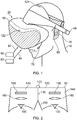
- a user 10 is wearing an HMD 20 (as an example of a generic head-mountable apparatus or virtual reality apparatus).
- the HMD comprises a frame 40, in this example formed of a rear strap and a top strap, and a display portion 50.
- HMD of Figure 1 may comprise further features, to be described below in connection with other drawings, but which are not shown in Figure 1 for clarity of this initial explanation.
- the HMD of Figure 1 completely (or at least substantially completely) obscures the user's view of the surrounding environment. All that the user can see is the pair of images displayed within the HMD.
- the HMD has associated headphone audio transducers or earpieces 60 which fit into the user's left and right ears 70.
- the earpieces 60 replay an audio signal provided from an external source, which may be the same as the video signal source which provides the video signal for display to the user's eyes.
- a boom microphone 75 is mounted on the HMD so as to extend towards the user's mouth.
- this HMD may be considered as a so-called "full immersion" HMD.
- the HMD is not a full immersion HMD, and may provide at least some facility for the user to see and/or hear the user's surroundings.
- a camera for example a camera mounted on the HMD
- a front-facing camera 122 may capture images to the front of the HMD, in use.
- a Bluetooth ® antenna 124 may provide communication facilities or may simply be arranged as a directional antenna to allow a detection of the direction of a nearby Bluetooth transmitter.
- a video signal is provided for display by the HMD.
- This could be provided by an external video signal source 80 such as a video games machine or data processing apparatus (such as a personal computer), in which case the signals could be transmitted to the HMD by a wired or a wireless connection 82.
- suitable wireless connections include Bluetooth ® connections.
- Audio signals for the earpieces 60 can be carried by the same connection.
- any control signals passed from the HMD to the video (audio) signal source may be carried by the same connection.
- a power supply 83 including one or more batteries and/or being connectable to a mains power outlet
- the power supply 83 and the video signal source 80 may be separate units or may be embodied as the same physical unit. There may be separate cables for power and video (and indeed for audio) signal supply, or these may be combined for carriage on a single cable (for example, using separate conductors, as in a USB cable, or in a similar way to a "power over Ethernet" arrangement in which data is carried as a balanced signal and power as direct current, over the same collection of physical wires).
- the video and/or audio signal may be carried by, for example, an optical fibre cable.
- at least part of the functionality associated with generating image and/or audio signals for presentation to the user may be carried out by circuitry and/or processing forming part of the HMD itself.
- a power supply may be provided as part of the HMD itself.
- embodiments of the disclosure are applicable to an HMD having at least one electrical and/or optical cable linking the HMD to another device, such as a power supply and/or a video (and/or audio) signal source. So, embodiments of the disclosure can include, for example:
- the physical position at which the cable 82 and/or 84 enters or joins the HMD is not particularly important from a technical point of view. Aesthetically, and to avoid the cable(s) brushing the user's face in operation, it would normally be the case that the cable(s) would enter or join the HMD at the side or back of the HMD (relative to the orientation of the user's head when worn in normal operation). Accordingly, the position of the cables 82, 84 relative to the HMD in Figure 1 should be treated merely as a schematic representation.
- Figure 1 provides an example of a head-mountable display system comprising a frame to be mounted onto an observer's head, the frame defining one or two eye display positions which, in use, are positioned in front of a respective eye of the observer and a display element mounted with respect to each of the eye display positions, the display element providing a virtual image of a video display of a video signal from a video signal source to that eye of the observer.
- Figure 1 shows just one example of an HMD.
- an HMD could use a frame more similar to that associated with conventional eyeglasses, namely a substantially horizontal leg extending back from the display portion to the top rear of the user's ear, possibly curling down behind the ear.
- the user's view of the external environment may not in fact be entirely obscured; the displayed images could be arranged so as to be superposed (from the user's point of view) over the external environment. An example of such an arrangement will be described below with reference to Figure 4 .
- FIG. 1 A schematic plan view of how this is achieved is provided as Figure 2 , which illustrates the positions 100 of the user's eyes and the relative position 110 of the user's nose.
- the display portion 50 in schematic form, comprises an exterior shield 120 to mask ambient light from the user's eyes and an internal shield 130 which prevents one eye from seeing the display intended for the other eye.
- the combination of the user's face, the exterior shield 120 and the interior shield 130 form two compartments 140, one for each eye.
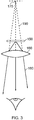
- a display element 150 and one or more optical elements 160 In each of the compartments there is provided a display element 150 and one or more optical elements 160. The way in which the display element and the optical element(s) cooperate to provide a display to the user will be described with reference to Figure 3 .
- the display element 150 generates a displayed image which is (in this example) refracted by the optical elements 160 (shown schematically as a convex lens but which could include compound lenses or other elements) so as to generate a virtual image 170 which appears to the user to be larger than and significantly further away than the real image generated by the display element 150.
- the virtual image may have an apparent image size (image diagonal) of more than 1 m and may be disposed at a distance of more than 1 m from the user's eye (or from the frame of the HMD). In general terms, depending on the purpose of the HMD, it is desirable to have the virtual image disposed a significant distance from the user.
- FIG. 4 An alternative arrangement is shown in Figure 4 .
- This arrangement may be used where it is desired that the user's view of the external environment is not entirely obscured. However, it is also applicable to HMDs in which the user's external view is wholly obscured.
- the display element 150 and optical elements 200 cooperate to provide an image which is projected onto a mirror 210, which deflects the image towards the user's eye position 220. The user perceives a virtual image to be located at a position 230 which is in front of the user and at a suitable distance from the user.
- the mirror 210 can be a substantially 100% reflective mirror.
- the arrangement of Figure 4 then has the advantage that the display element and optical elements can be located closer to the centre of gravity of the user's head and to the side of the user's eyes, which can produce a less bulky HMD for the user to wear.
- the mirror 210 can be made partially reflective so that the user sees the external environment, through the mirror 210, with the virtual image superposed over the real external environment.
- FIG. 5 An example of a pair of stereoscopic images for display to the left and right eyes is shown in Figure 5 .
- the images exhibit a lateral displacement relative to one another, with the displacement of image features depending upon the (real or simulated) lateral separation of the cameras by which the images were captured, the angular convergence of the cameras and the (real or simulated) distance of each image feature from the camera position.
- the lateral displacements in Figure 5 could in fact be the other way round, which is to say that the left eye image as drawn could in fact be the right eye image, and the right eye image as drawn could in fact be the left eye image.
- the left eye image as drawn could in fact be the right eye image
- the right eye image as drawn could in fact be the left eye image.
- some stereoscopic displays tend to shift objects to the right in the right eye image and to the left in the left eye image, so as to simulate the idea that the user is looking through a stereoscopic window onto the scene beyond.
- some HMDs use the arrangement shown in Figure 5 because this gives the impression to the user that the user is viewing the scene through a pair of binoculars. The choice between these two arrangements is at the discretion of the system designer.
- an HMD may be used simply to view movies and the like. In this case, there is no change required to the apparent viewpoint of the displayed images as the user turns the user's head, for example from side to side. In other uses, however, such as those associated with virtual reality (VR) or augmented reality (AR) systems, the user's viewpoint needs to track movements with respect to a real or virtual space in which the user is located.
- VR virtual reality
- AR augmented reality
- FIG. 6 schematically illustrates an example virtual reality system and in particular shows a user wearing an HMD connected to a Sony ® PlayStation 3 ® games console 300 as an example of a base device.
- the games console 300 is connected to a mains power supply 310 and (optionally) to a main display screen (not shown).
- a cable acting as the cables 82, 84 discussed above (and so acting as both power supply and signal cables), links the HMD 20 to the games console 300 and is, for example, plugged into a USB socket 320 on the console 300.
- a single physical cable is provided which fulfils the functions of the cables 82, 84.
- the video displays in the HMD 20 are arranged to display images generated by the games console 300, and the earpieces 60 in the HMD 20 are arranged to reproduce audio signals generated by the games console 300. Note that if a USB type cable is used, these signals will be in digital form when they reach the HMD 20, such that the HMD 20 comprises a digital to analogue converter (DAC) to convert at least the audio signals back into an analogue form for reproduction.
- DAC digital to analogue converter
- Images from the camera 122 mounted on the HMD 20 are passed back to the games console 300 via the cable 82, 84.
- signals from those sensors may be at least partially processed at the HMD 20 and/or may be at least partially processed at the games console 300. The use and processing of such signals will be described further below.
- the USB connection from the games console 300 also provides power to the HMD 20, according to the USB standard.
- Figure 6 also shows a separate display 305 such as a television or other openly viewable display (by which it is meant that viewers other than the HMD wearer may see images displayed by the display 305) and a camera 315, which may be (for example) directed towards the user (such as the HMD wearer) during operation of the apparatus.
- a suitable camera is the PlayStation Eye camera, although more generally a generic "webcam", connected to the console 300 by a wired (such as a USB) or wireless (such as WiFi or Bluetooth) connection.
- the display 305 may be arranged (under the control of the games console) to provide the function of a so-called "social screen". It is noted that playing a computer game using an HMD can be very engaging for the wearer of the HMD but less so for other people in the vicinity (particularly if they are not themselves also wearing HMDs). To provide an improved experience for a group of users, where the number of HMDs in operation is fewer than the number of users, images can be displayed on a social screen. The images displayed on the social screen may be substantially similar to those displayed to the user wearing the HMD, so that viewers of the social screen see the virtual environment (or a subset, version or representation of it) as seen by the HMD wearer.
- the social screen could display other material such as information relating to the HMD wearer's current progress through the ongoing computer game.
- the HMD wearer could see the game environment from a first person viewpoint whereas the social screen could provide a third person view of activities and movement of the HMD wearer's avatar, or an overview of a larger portion of the virtual environment.
- an image generator (for example, a part of the functionality of the games console) is configured to generate some of the virtual environment images for display by a display separate to the head mountable display.
- haptic gloves 331 can include actuators to provide haptic feedback to the user, for example under the control of processing carried out by the console 300. They may also provide configuration and/or location sensing as discussed below.
- haptic interfaces can be used, providing one or more actuators and/or one or more sensors.
- a so-called haptics suit may be worn by the user.
- Haptic shoes may include one or more actuators and one or more sensors.
- the user could stand on or hold a haptic interface device.
- the one or more actuators associated with these devices may have different respective frequency responses and available amplitudes of vibration. Therefore in example arrangements to be discussed below the haptic generator can be responsive to attributes defining one or capabilities of the haptic interface.
- an attribute defines a frequency response of the haptic interface.
- an attribute defines a maximum amplitude which may be represented by the haptic interface.
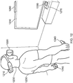
- FIG. 7 schematically illustrates a similar arrangement (another example of a virtual reality system) in which the games console is connected (by a wired or wireless link) to a so-called "break out box" acting as a base or intermediate device 350, to which the HMD 20 is connected by a cabled link 82, 84.
- the breakout box has various functions in this regard.
- One function is to provide a location, near to the user, for some user controls relating to the operation of the HMD, such as (for example) one or more of a power control, a brightness control, an input source selector, a volume control and the like.
- Another function is to provide a local power supply for the HMD (if one is needed according to the embodiment being discussed).
- Another function is to provide a local cable anchoring point.
- the break-out box 350 is fixed to the ground or to a piece of furniture, but rather than having a very long trailing cable from the games console 300, the break-out box provides a locally weighted point so that the cable 82, 84 linking the HMD 20 to the break-out box will tend to move around the position of the break-out box. This can improve user safety and comfort by avoiding the use of very long trailing cables.
- the user is also shown holding a pair of hand-held controller 330s which may be, for example, Sony ® Move ® controllers which communicate wirelessly with the games console 300 to control (or to contribute to the control of) game operations relating to a currently executed game program.
- the user may also be wearing one or two haptic gloves as discussed in connection with Figure 6 .
- an HMD may form part of a set or cohort of interconnected devices (that is to say, interconnected for the purposes of data or signal transfer, but not necessarily connected by a physical cable).
- processing which is described as taking place “at” one device, such as at the HMD could be devolved to another device such as the games console (base device) or the break-out box.
- Processing tasks can be shared amongst devices.
- Source signals, on which the processing is to take place, could be distributed to another device, or the processing results from the processing of those source signals could be sent to another device, as required. So any references to processing taking place at a particular device should be understood in this context.
- the user's viewpoint needs to track movements with respect to a real or virtual space in which the user is located.
- This tracking is carried out by detecting motion of the HMD and varying the apparent viewpoint of the displayed images so that the apparent viewpoint tracks the motion.
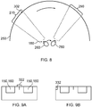
- Figure 8 schematically illustrates the effect of a user head movement in a VR or AR system.
- a virtual environment is represented by a (virtual) spherical shell 250 around a user.
- This provides an example of a virtual display screen (VDS).
- VDS virtual display screen
- a user is initially at a first position 260 and is directed towards a portion 270 of the virtual environment. It is this portion 270 which is represented in the images displayed on the display elements 150 of the user's HMD. It can be seen from the drawing that the VDS subsists in three dimensional space (in a virtual sense) around the position in space of the HMD wearer, such that the HMD wearer sees a current portion of VDS according to the HMD orientation.
- the displayed portion of the virtual environment also moves so that, at the end of the movement, a new portion 290 is displayed by the HMD.
- the apparent viewpoint within the virtual environment moves with the head movement. If the head rotates to the right side, for example, as shown in Figure 8 , the apparent viewpoint also moves to the right from the user's point of view. If the situation is considered from the aspect of a displayed object, such as a displayed object 300, this will effectively move in the opposite direction to the head movement. So, if the head movement is to the right, the apparent viewpoint moves to the right but an object such as the displayed object 300 which is stationary in the virtual environment will move towards the left of the displayed image and eventually will disappear off the left-hand side of the displayed image, for the simple reason that the displayed portion of the virtual environment has moved to the right whereas the displayed object 300 has not moved in the virtual environment.
- FIGS 9a and 9b schematically illustrated HMDs with motion sensing.
- the two drawings are in a similar format to that shown in Figure 2 . That is to say, the drawings are schematic plan views of an HMD, in which the display element 150 and optical elements 160 are represented by a simple box shape. Many features of Figure 2 are not shown, for clarity of the diagrams. Both drawings show examples of HMDs with a motion detector for detecting motion of the observer's head.
- a forward-facing camera 322 is provided on the front of the HMD. This may be the same camera as the camera 122 discussed above, or may be an additional camera. This does not necessarily provide images for display to the user (although it could do so in an augmented reality arrangement). Instead, its primary purpose in the present embodiments is to allow motion sensing. A technique for using images captured by the camera 322 for motion sensing will be described below in connection with Figure 10 .
- the motion detector comprises a camera mounted so as to move with the frame; and an image comparator operable to compare successive images captured by the camera so as to detect inter-image motion.
- Figure 9b makes use of a hardware motion detector 332.
- This can be mounted anywhere within or on the HMD.
- suitable hardware motion detectors are piezoelectric accelerometers or optical fibre gyroscopes. It will of course be appreciated that both hardware motion detection and camera-based motion detection can be used in the same device, in which case one sensing arrangement could be used as a backup when the other one is unavailable, or one sensing arrangement (such as the camera) could provide data for changing the apparent viewpoint of the displayed images, whereas the other (such as an accelerometer) could provide data for image stabilisation.
- Figure 10 schematically illustrates one example of motion detection using the camera 322 of Figure 9a .
- the camera 322 is a video camera, capturing images at an image capture rate of, for example, 25 images per second. As each image is captured, it is passed to an image store 400 for storage and is also compared, by an image comparator 410, with a preceding image retrieved from the image store. The comparison uses known block matching techniques (so-called "optical flow” detection) to establish whether substantially the whole image has moved since the time at which the preceding image was captured.
- Localised motion might indicate moving objects within the field of view of the camera 322, but global motion of substantially the whole image would tend to indicate motion of the camera rather than of individual features in the captured scene, and in the present case because the camera is mounted on the HMD, motion of the camera corresponds to motion of the HMD and in turn to motion of the user's head.
- the displacement between one image and the next, as detected by the image comparator 410, is converted to a signal indicative of motion by a motion detector 420. If required, the motion signal is converted by to a position signal by an integrator 430.
- the HMD can detect head motion using a mechanical or solid state detector 332 such as an accelerometer.
- a mechanical or solid state detector 332 such as an accelerometer.
- the detector 332 can be better suited for use with higher frequency motion detection.
- a high image rate camera such as a 200 Hz capture rate camera
- a camera-based system may be more appropriate.
- the detector 332 could take the place of the camera 322, the image store 400 and the comparator 410, so as to provide an input directly to the motion detector 420. Or the detector 332 could take the place of the motion detector 420 as well, directly providing an output signal indicative of physical motion.
- position or motion detecting techniques are of course possible.
- a mechanical arrangement by which the HMD is linked by a moveable pantograph arm to a fixed point may be used, with position and orientation sensors detecting changes in the deflection of the pantograph arm.
- a system of one or more transmitters and receivers, mounted on the HMD and on a fixed point can be used to allow detection of the position and orientation of the HMD by triangulation techniques.
- the HMD could carry one or more directional transmitters, and an array of receivers associated with known or fixed points could detect the relative signals from the one or more transmitters.
- the transmitters could be fixed and the receivers could be on the HMD.
- transmitters and receivers include infra-red transducers, ultrasonic transducers and radio frequency transducers.
- the radio frequency transducers could have a dual purpose, in that they could also form part of a radio frequency data link to and/or from the HMD, such as a Bluetooth ® link.
- Figure 11 schematically illustrates image processing carried out in response to a detected position or change in position of the HMD.
- the apparent viewpoint of the video being displayed to the user of the HMD is changed in response to a change in actual position or orientation of the user's head.
- a motion sensor 450 (such as the arrangement of Figure 10 and/or the motion detector 332 of Figure 9b ) supplying data indicative of motion and/or current position to a required image position detector 460, which translates the actual position of the HMD into data defining the required image for display.
- An image generator 480 accesses image data stored in an image store 470 if required, and generates the required images from the appropriate viewpoint for display by the HMD.
- the external video signal source can provide the functionality of the image generator 480 and act as a controller to compensate for the lower frequency component of motion of the observer's head by changing the viewpoint of the displayed image so as to move the displayed image in the opposite direction to that of the detected motion so as to change the apparent viewpoint of the observer in the direction of the detected motion.
- Figure 12 schematically illustrates a user wearing an HMD and engaged in a video game.
- the arrangement of Figure 12 is similar to that of Figure 7 discussed above, but for clarity of the diagram the cabled connections 82, 84 and the optional break-out box 350 of Figure 7 are not shown.
- Figure 12 does illustrate an example of the relative positioning of the user and other components in normal operation.
- the user 1200 is wearing an HMD 1210 having one or more markers 1220 at the front of the HMD (where the term "front” is relative to an orientation of the user's head) and one or more markers 1230 at the rear of the HMD, for example, on a head strap.
- the user carries a hand held controller 1240 in each hand (in this example).
- the user is facing a television screen 1250.
- facing the television screen provides a natural orientation to other components of the apparatus.
- the television screen may, as discussed above, provide a so-called "social screen” representing images indicative of game action being played by the user 1200, for the enjoyment of other nearby people who are not wearing HMDs.
- a light bar 1260 Situated around the television screen are a light bar 1260, to be discussed below, a games console 1270 and a camera 1280.
- one or more of the devices have at least one camera and using the camera, the devices detect the positions (or at least the relative positions) of other ones of the devices by means of detecting markers in captured images.
- the HMD comprises front and rear markers as discussed; the light bar 1260 can provide a marker indicating a location of or relative to the television screen console, and the hand-held controllers 1240 can provide respective markers.
- Other devices for example, a second HMD worn by another user, and/or one or more other peripheral devices
- the devices share the data defining the relative positions of other devices, as detected using the respective cameras, so that collectively, or via a master device such as the console 1270 handling the collection and amalgamation of the position data, a map or specification of the positions within the game playing area of each of the devices can be derived based on their respective relative position detections.
- the front surface 1300 of the HMD worn by the user has a plurality of LEDs (or other light emitting portions, illuminated portions, or passive features 1310) disposed so that those features can be detected by a camera detected towards the HMD.
- the LEDs or features 1310 can collectively be considered as a "marker" having multiple marker portions (such as the individual LEDs).
- a reason for having multiple marker portions is to assist in distinguishing the marker from other image features in the captured images.
- having multiple marker portions allows an estimation of the separation distance from the camera to the detected marker, in that the distance (in the captured images) between marker portions such as LEDs will be smaller for a more distant HMD (with respect to the camera capturing the images) and larger for a closer HMD.
- the marker comprises two or more spatially separated marker portions; and the detector is configured to detect respective image locations of images of the marker portions in the given captured image
- Figure 14 schematically illustrates a rear view of the HMD in which a further marker comprising multiple marker portions 1400 is provided. So, if the user turns his back on the console and its associated camera, or if other peripheral devices are disposed behind the user in use, the location of the HMD can still be optically detected using a camera.
- Figure 15 schematically illustrates a light bar of the type shown in Figure 12 , having a marker comprising marker portions (such as LEDs) 1500, 1510.
- a further LED 1520 can be provided, for example to give timing information to the other devices in the system.
- the optical position detections by other devices in the overall apparatus can be synchronised to a common time frame specified by the console.
- the LED 1520 By positioning the LED 1520 between the marker portions 1500, 1510, its location can be inferred in a captured image even when the LED 1520 is not currently illuminated. So, a pattern of illumination and non-illumination can be detected for the LED 1520 by virtue of its location relative to the marker portions 1500, 1510.
- Figure 16 schematically illustrates a camera 1600 associated with the console and, in the example of Figure 12 , positioned close to the position of the console.
- Figure 17 schematically illustrates a hand-held controller 1700 having a marker 1710 formed of multiple marker portions 1720 disposed at its distal end.
- a camera 1730 may also be provided.
- each of the devices shown in Figure 12 may provide a marker having one or more marker portions and a camera.
- the camera is the camera 1600 of Figure 16 .
- the camera is provided as the camera 1730 of Figure 17 .
- multiple cameras may be provided, such as cameras 1320, 1330 facing forwards and a camera 1410 facing backwards.
- Figure 18 schematically illustrates a data processing device, for example representing one or more of: the HMD, the handheld controller(s) and the console of Figure 12 . Only those features relative to the current discussion are shown in Figure 18 ; other data processing functionality not shown in Figure 18 may also be provided.
- the data processing device 1800 comprises a camera 1810 configured to capture successive images. As discussed below, each image is captured during a respective image capture period and a so-called rolling shutter is used such that respective different portions of the captured image are captured at respective different capture times within the image capture period.
- a detector 1820 is arranged to detect, from images captured by the camera 1810, information indicating a relative location of a remote marker with respect to the data processing device 1800, and to associate a time stamp with a detected relative location indicating a time at which the relative location was detected.
- a motion sensor 1830 such as an inertial motion sensor is arranged to detect motion of the data processing device 1800 and to control operation of the detector 1820 in response to the detected motion.
- the data processing device 1800 may also provide a marker 1840, for example having one or more marker portions as discussed above.
- a communications (“comms") module 1850 provides data communication with other data processing devices in the overall apparatus.
- Figure 19 schematically illustrates the detector 1820, shown comprising a location detector 1900 and a time controller 1910.
- the detector is configured to detect an image of the marker within a given captured image and to derive a respective time stamp in dependence upon a location within the given captured image of the image of the marker. This arrangement will be described further with reference to Figure 20 below.
- Figure 20 is a schematic diagram illustrating the operation of a rolling camera shutter.
- an image such as the image 2000 of Figure 20 is captured during an image capture period 2010. Different portions of the image are captured at different respective times within the image capture period.
- the example of Figure 20 relates to a vertical-scanning rolling shutter such that the image 2000 is captured on a line-by-line basis (the lines being lines of pixels, for example) such that each line is captured at a different time within the image capture period.
- the rolling shutter can be implemented from the top 2020 to bottom 2030 of the image using an example temporal relationship such as that represented by a curve 2040 so that the first line of pixels to be captured and output is a top line as drawn, and the last is a bottom line as drawn.
- a corresponding capture time t 1 2060 can be derived using the relationship defined by the curve 2040.
- the camera is configured to capture the successive images as multiple lines of pixels, such that respective different lines of pixels of the captured image are captured at respective different capture times within the image capture period.
- the rolling shutter can be implemented in a vertical or a horizontal sense, and in either direction. So, in other embodiments, the rolling shutter might be such that the bottom line of pixels of the image 2000 is captured first and the top line is captured last.
- Rolling shutters can be implemented mechanically or electronically. Many examples of image sensors using electronic rolling shutters employ so-called CMOS sensors. This is the type of sensor used in the present examples.
- a time stamp can be associated with an image feature in the captured image according to the vertical (in this example) position of that image feature within the captured image.
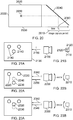
- Figures 21A and 21B schematically illustrate the operation of the apparatus described above using a camera 2100 capturing an image of a marker 2110 having (in this example) three marker portions 2120 facing the camera 2100.
- the captured image 2130 contains images 2140 of the three marker portions and, using the time-relationship 2040 discussed above, a time stamp t is associated with the captured marker according to a geometric vertical centre position 2150 of the captured marker portions.
- Figures 22A.... 23B schematically illustrate situations in which one or both of the camera and the marker is moving, for example in a vertical direction (relative to a current orientation of the camera) during capture of the image of the marker.
- the camera 2200 is moving upwards and/or the marker 2210 is moving downwards during the image capture period, which gives rise to an elongated set of captured images 2220 of the marker portions.
- the motion sensor 1830 detects camera motion (and, in other embodiments to be discussed below, a separate motion sensor can detect marker motion) and, in response to the detected motion, applies a transformation to the detected image locations (of the captured marker portions 2220 in dependence upon motion of the device (or indeed the marker) detected by the motion sensor.
- the transformation results in the lowest marker portion (being a marker portion captured later during the period of motion) 2230 having its position transformed to a transformed position 2240 such that instead of detecting a geometrical vertical centre 2250, a transformed geometrical vertical centre 2260 on which the time stamp t is based is derived. Therefore, in these examples, the detector is configured to apply a transformation to the detected image locations in dependence upon motion of the data processing device detected by the motion sensor.
- the transformation is configured to transform one or more of the detected image locations in dependence upon the capture times within the image captured period of the detected image locations.
- the transformation is configured to provide a mapping of the detected image locations towards mapped image locations at which the respective marker portions would have been captured if the device had been stationary during the image capture period.
- the camera 2300 is moving downwards and/or the marker 2310 is moving upwards giving rise to a foreshortened set of captured marker portions, the later, captured one of which 2320 is transformed to a transformed position 2330 giving rise to a time stamp based on a transformed geometrical vertical centre 2340 rather than the original centre 2350.
- the device which has a camera and which captures images of another device may not necessarily be the same device that derives relative position information from those captured images. Also, one or both of camera motion data and marker motion data can be taken into account in deriving the relative location information.
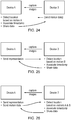
- FIGs 24 to 26 schematically illustrate a data processing apparatus comprising two data processing devices.
- An actual system may comprise more than two devices.
- Each of the devices (labelled as “device A” and “device B") can be any of the device types shown in Figure 12 such as an HMD or another type of device, or indeed other peripheral or control or display devices.
- Example arrangements can encompass a device and a marker, or a pair or larger group of devices.
- Example arrangements can encompass a marker.
- device A has a camera which captures images of a marker provided at device B.
- device B can send motion data indicative of motion of the marker to device A.
- Device A detects the relative location of devices A and B based upon at least the motion of device A (being the camera motion) and optionally upon the motion of device B being the marker motion.
- the device A associates a time stamp with the detection in the manner discussed above, and optionally can share the location data with device B and any other devices in the apparatus.
- the image capture is carried out by device A but much of the processing is carried out by device B. This may be appropriate in the situation where device A is a low-powered device such as a hand-held controller and device B is a higher-powered device such as a console.
- Device A captures images of the marker at device B and sends representations of those images to device B.
- Device B detects the relative location of devices A and B based on motion data indicative of the marker motion.
- Device B associates a time stamp with the detected location and, optionally, shares the location data with device A and any other devices.
- the device B provides an example of a data processing device comprising: a receiver (such as the comms unit of device B) to receive data representing successive images of a marker captured by a second, remote, data processing device, each image being captured during a respective image capture period such that respective different portions of the captured image are captured at respective different times within the image capture period; a detector to detect, from the data representing the captured images, information indicating a relative location of the marker with respect to the second data processing device, and to associate a timestamp with a detected relative location indicating a time at which the relative location was detected; and a motion sensor to detect motion of the data processing device and to control operation of the detector in response to the detected motion.
- a receiver such as the comms unit of device B
- device A captures images of the marker at device B and sends representations of those images along with motion data indicative of device A motion (that is, camera motion) to device B.
- Device B detects the location of the two devices based upon the captured images and at least the motion of device A, optionally also using the motion of device B.
- Device B associates a timestamp with the detected location information and optionally shares the data with device A and any other devices in the system.
- Figure 27 schematically illustrates a data processing method comprising:
- Figure 28 schematically illustrates a data processing method comprising:
- example embodiments can be implemented by computer software operating on a general purpose computing system such as a games machine.
- computer software which when executed by a computer, causes the computer to carry out any of the methods discussed above is considered as an embodiment of the present disclosure.
- embodiments of the disclosure are provided by a non-transitory, machine-readable storage medium which stores such computer software.
Landscapes
- Engineering & Computer Science (AREA)
- Theoretical Computer Science (AREA)
- Physics & Mathematics (AREA)
- General Engineering & Computer Science (AREA)
- General Physics & Mathematics (AREA)
- Human Computer Interaction (AREA)
- Optics & Photonics (AREA)
- Computing Systems (AREA)
- Computer Graphics (AREA)
- Geometry (AREA)
- Signal Processing (AREA)
- Multimedia (AREA)
- User Interface Of Digital Computer (AREA)
- Controls And Circuits For Display Device (AREA)
Description
- This disclosure relates to virtual reality systems and methods.
- The "background" description provided herein is for the purpose of generally presenting the context of the disclosure. Work of the presently named inventors, to the extent it is described in this background section, as well as aspects of the description which may not otherwise qualify as prior art at the time of filing, are neither expressly or impliedly admitted as prior art against the present disclosure.
- A head-mountable display (HMD) is one example of a head-mountable apparatus for use in a virtual reality system in which an HMD wearer views a virtual environment. In an HMD, an image or video display device is provided which may be worn on the head or as part of a helmet. Either one eye or both eyes are provided with small electronic display devices.
- It has been proposed to provide detection arrangements for detecting a relative location of one device (such as an HMD) from another device, by using a camera on the one device to detect images of one or more markers, for example on the other device.
- Although the original development of HMDs and virtual reality was perhaps driven by the military and professional applications of these devices, HMDs are becoming more popular for use by casual users in, for example, computer game or domestic computing applications. Previously proposed arrangements are disclosed in
US 2015/094142 A1 ,US 2016/214015 A1 ,US 2016/235323 A1 andUS 2016/219208 A1 . - In particular,
US 2015/094142 A1 discloses a system for warning a user of a head mounted display during gameplay of a video game comprising one or more cameras provided within the HMD as well as external cameras that are dispersed within a real-world scene of the user wearing the HMD. Captured images/video frames are analyzed to detect position of the HMD and/or the controller of each player by determining location of various markers on each of the HMDs. The HMD data processing module analyzes the positional data of the HMD worn by the user to adjust content and/or provide warning messages. - The foregoing paragraphs have been provided by way of general introduction, and are not intended to limit the scope of the following claims. The described embodiments, together with further advantages, will be best understood by reference to the following detailed description taken in conjunction with the accompanying drawings.
- The invention is defined by the appended claims.
- Various other aspects and features of the present disclosure are defined in the appended claims and within the text of the accompanying description and include at least a head mountable apparatus such as a display and a method of operating a head-mountable apparatus as well as a computer program.
- A more complete appreciation of the disclosure and many of the attendant advantages thereof will be readily obtained as the same becomes better understood by reference to the following detailed description when considered in connection with the accompanying drawings, wherein:
-
Figure 1 schematically illustrates an HMD worn by a user; -
Figure 2 is a schematic plan view of an HMD; -
Figure 3 schematically illustrates the formation of a virtual image by an HMD; -
Figure 4 schematically illustrates another type of display for use in an HMD; -
Figure 5 schematically illustrates a pair of stereoscopic images; -
Figures 6 and7 schematically illustrate a user wearing an HMD connected to a Sony® PlayStation 3® games console; -
Figure 8 schematically illustrates a change of view of user of an HMD; -
Figures 9a and 9b schematically illustrate HMDs with motion sensing; -
Figure 10 schematically illustrates a position sensor based on optical flow detection; -
Figure 11 schematically illustrates image processing carried out in response to a detected position or change in position of an HMD; -
Figure 12 schematically illustrates a user wearing an HMD and engaged in a video game; -
Figures 13 and 14 are respective front and rear schematic views of and HMD; -
Figure 15 schematically illustrates a light bar; -
Figure 16 schematically illustrates a camera; -
Figure 17 schematically illustrates a hand-held controller; -
Figure 18 schematically illustrates a data processing device; -
Figure 19 schematically illustrates a detector; -
Figure 20 is a schematic diagram illustrating the operation of a rolling camera shutter; -
Figures 21A to 23B schematically illustrate the effect on captured images of camera and/or marker motion during an image capture period; -
Figures 24 to 26 schematically illustrate data processing apparatus in different respective modes of operation; and -
Figures 27 and 28 schematically illustrate respective methods not forming part of the present invention. - Referring now to
Figure 1 , auser 10 is wearing an HMD 20 (as an example of a generic head-mountable apparatus or virtual reality apparatus). The HMD comprises aframe 40, in this example formed of a rear strap and a top strap, and adisplay portion 50. - Note that the HMD of
Figure 1 may comprise further features, to be described below in connection with other drawings, but which are not shown inFigure 1 for clarity of this initial explanation. - The HMD of
Figure 1 completely (or at least substantially completely) obscures the user's view of the surrounding environment. All that the user can see is the pair of images displayed within the HMD. - The HMD has associated headphone audio transducers or
earpieces 60 which fit into the user's left andright ears 70. Theearpieces 60 replay an audio signal provided from an external source, which may be the same as the video signal source which provides the video signal for display to the user's eyes. Aboom microphone 75 is mounted on the HMD so as to extend towards the user's mouth. - The combination of the fact that the user can see only what is displayed by the HMD and, subject to the limitations of the noise blocking or active cancellation properties of the earpieces and associated electronics, can hear only what is provided via the earpieces, mean that this HMD may be considered as a so-called "full immersion" HMD. Note however that in some embodiments the HMD is not a full immersion HMD, and may provide at least some facility for the user to see and/or hear the user's surroundings. This could be by providing some degree of transparency or partial transparency in the display arrangements, and/or by projecting a view of the outside (captured using a camera, for example a camera mounted on the HMD) via the HMD's displays, and/or by allowing the transmission of ambient sound past the earpieces and/or by providing a microphone to generate an input sound signal (for transmission to the earpieces) dependent upon the ambient sound.
- A front-facing
camera 122 may capture images to the front of the HMD, in use. A Bluetooth®antenna 124 may provide communication facilities or may simply be arranged as a directional antenna to allow a detection of the direction of a nearby Bluetooth transmitter. - In operation, a video signal is provided for display by the HMD. This could be provided by an external
video signal source 80 such as a video games machine or data processing apparatus (such as a personal computer), in which case the signals could be transmitted to the HMD by a wired or awireless connection 82. Examples of suitable wireless connections include Bluetooth® connections. Audio signals for theearpieces 60 can be carried by the same connection. Similarly, any control signals passed from the HMD to the video (audio) signal source may be carried by the same connection. Furthermore, a power supply 83 (including one or more batteries and/or being connectable to a mains power outlet) may be linked by acable 84 to the HMD. Note that thepower supply 83 and thevideo signal source 80 may be separate units or may be embodied as the same physical unit. There may be separate cables for power and video (and indeed for audio) signal supply, or these may be combined for carriage on a single cable (for example, using separate conductors, as in a USB cable, or in a similar way to a "power over Ethernet" arrangement in which data is carried as a balanced signal and power as direct current, over the same collection of physical wires). The video and/or audio signal may be carried by, for example, an optical fibre cable. In other embodiments, at least part of the functionality associated with generating image and/or audio signals for presentation to the user may be carried out by circuitry and/or processing forming part of the HMD itself. A power supply may be provided as part of the HMD itself. - Some embodiments of the disclosure are applicable to an HMD having at least one electrical and/or optical cable linking the HMD to another device, such as a power supply and/or a video (and/or audio) signal source. So, embodiments of the disclosure can include, for example:
- (a) an HMD having its own power supply (as part of the HMD arrangement) but a cabled connection to a video and/or audio signal source;
- (b) an HMD having a cabled connection to a power supply and to a video and/or audio signal source, embodied as a single physical cable or more than one physical cable;
- (c) an HMD having its own video and/or audio signal source (as part of the HMD arrangement) and a cabled connection to a power supply;
- (d) an HMD having a wireless connection to a video and/or audio signal source and a cabled connection to a power supply; or
- (e) an HMD having its own video and/or audio signal source and its own power supply (both as part of the HMD arrangement).
- If one or more cables are used, the physical position at which the
cable 82 and/or 84 enters or joins the HMD is not particularly important from a technical point of view. Aesthetically, and to avoid the cable(s) brushing the user's face in operation, it would normally be the case that the cable(s) would enter or join the HMD at the side or back of the HMD (relative to the orientation of the user's head when worn in normal operation). Accordingly, the position of thecables Figure 1 should be treated merely as a schematic representation. - Accordingly, the arrangement of
Figure 1 provides an example of a head-mountable display system comprising a frame to be mounted onto an observer's head, the frame defining one or two eye display positions which, in use, are positioned in front of a respective eye of the observer and a display element mounted with respect to each of the eye display positions, the display element providing a virtual image of a video display of a video signal from a video signal source to that eye of the observer. -
Figure 1 shows just one example of an HMD. Other formats are possible: for example an HMD could use a frame more similar to that associated with conventional eyeglasses, namely a substantially horizontal leg extending back from the display portion to the top rear of the user's ear, possibly curling down behind the ear. In other (not full immersion) examples, the user's view of the external environment may not in fact be entirely obscured; the displayed images could be arranged so as to be superposed (from the user's point of view) over the external environment. An example of such an arrangement will be described below with reference toFigure 4 . - In the example of
Figure 1 , a separate respective display is provided for each of the user's eyes. A schematic plan view of how this is achieved is provided asFigure 2 , which illustrates thepositions 100 of the user's eyes and therelative position 110 of the user's nose. Thedisplay portion 50, in schematic form, comprises anexterior shield 120 to mask ambient light from the user's eyes and aninternal shield 130 which prevents one eye from seeing the display intended for the other eye. The combination of the user's face, theexterior shield 120 and theinterior shield 130 form twocompartments 140, one for each eye. In each of the compartments there is provided adisplay element 150 and one or moreoptical elements 160. The way in which the display element and the optical element(s) cooperate to provide a display to the user will be described with reference toFigure 3 . - Referring to
Figure 3 , thedisplay element 150 generates a displayed image which is (in this example) refracted by the optical elements 160 (shown schematically as a convex lens but which could include compound lenses or other elements) so as to generate avirtual image 170 which appears to the user to be larger than and significantly further away than the real image generated by thedisplay element 150. As an example, the virtual image may have an apparent image size (image diagonal) of more than 1 m and may be disposed at a distance of more than 1 m from the user's eye (or from the frame of the HMD). In general terms, depending on the purpose of the HMD, it is desirable to have the virtual image disposed a significant distance from the user. For example, if the HMD is for viewing movies or the like, it is desirable that the user's eyes are relaxed during such viewing, which requires a distance (to the virtual image) of at least several metres. InFigure 3 , solid lines (such as the line 180) are used to denote real optical rays, whereas broken lines (such as the line 190) are used to denote virtual rays. - An alternative arrangement is shown in
Figure 4 . This arrangement may be used where it is desired that the user's view of the external environment is not entirely obscured. However, it is also applicable to HMDs in which the user's external view is wholly obscured. In the arrangement ofFigure 4 , thedisplay element 150 andoptical elements 200 cooperate to provide an image which is projected onto amirror 210, which deflects the image towards the user'seye position 220. The user perceives a virtual image to be located at aposition 230 which is in front of the user and at a suitable distance from the user. - In the case of an HMD in which the user's view of the external surroundings is entirely obscured, the
mirror 210 can be a substantially 100% reflective mirror. The arrangement ofFigure 4 then has the advantage that the display element and optical elements can be located closer to the centre of gravity of the user's head and to the side of the user's eyes, which can produce a less bulky HMD for the user to wear. Alternatively, if the HMD is designed not to completely obscure the user's view of the external environment, themirror 210 can be made partially reflective so that the user sees the external environment, through themirror 210, with the virtual image superposed over the real external environment. - In the case where separate respective displays are provided for each of the user's eyes, it is possible to display stereoscopic images. An example of a pair of stereoscopic images for display to the left and right eyes is shown in
Figure 5 . The images exhibit a lateral displacement relative to one another, with the displacement of image features depending upon the (real or simulated) lateral separation of the cameras by which the images were captured, the angular convergence of the cameras and the (real or simulated) distance of each image feature from the camera position. - Note that the lateral displacements in
Figure 5 could in fact be the other way round, which is to say that the left eye image as drawn could in fact be the right eye image, and the right eye image as drawn could in fact be the left eye image. This is because some stereoscopic displays tend to shift objects to the right in the right eye image and to the left in the left eye image, so as to simulate the idea that the user is looking through a stereoscopic window onto the scene beyond. However, some HMDs use the arrangement shown inFigure 5 because this gives the impression to the user that the user is viewing the scene through a pair of binoculars. The choice between these two arrangements is at the discretion of the system designer. - In some situations, an HMD may be used simply to view movies and the like. In this case, there is no change required to the apparent viewpoint of the displayed images as the user turns the user's head, for example from side to side. In other uses, however, such as those associated with virtual reality (VR) or augmented reality (AR) systems, the user's viewpoint needs to track movements with respect to a real or virtual space in which the user is located.
-
Figure 6 schematically illustrates an example virtual reality system and in particular shows a user wearing an HMD connected to a Sony® PlayStation 3®games console 300 as an example of a base device. Thegames console 300 is connected to amains power supply 310 and (optionally) to a main display screen (not shown). A cable, acting as thecables HMD 20 to thegames console 300 and is, for example, plugged into aUSB socket 320 on theconsole 300. Note that in the present embodiments, a single physical cable is provided which fulfils the functions of thecables - The video displays in the
HMD 20 are arranged to display images generated by thegames console 300, and theearpieces 60 in theHMD 20 are arranged to reproduce audio signals generated by thegames console 300. Note that if a USB type cable is used, these signals will be in digital form when they reach theHMD 20, such that theHMD 20 comprises a digital to analogue converter (DAC) to convert at least the audio signals back into an analogue form for reproduction. - Images from the
camera 122 mounted on theHMD 20 are passed back to thegames console 300 via thecable HMD 20, signals from those sensors may be at least partially processed at theHMD 20 and/or may be at least partially processed at thegames console 300. The use and processing of such signals will be described further below. - The USB connection from the
games console 300 also provides power to theHMD 20, according to the USB standard. -
Figure 6 also shows aseparate display 305 such as a television or other openly viewable display (by which it is meant that viewers other than the HMD wearer may see images displayed by the display 305) and acamera 315, which may be (for example) directed towards the user (such as the HMD wearer) during operation of the apparatus. An example of a suitable camera is the PlayStation Eye camera, although more generally a generic "webcam", connected to theconsole 300 by a wired (such as a USB) or wireless (such as WiFi or Bluetooth) connection. - The
display 305 may be arranged (under the control of the games console) to provide the function of a so-called "social screen". It is noted that playing a computer game using an HMD can be very engaging for the wearer of the HMD but less so for other people in the vicinity (particularly if they are not themselves also wearing HMDs). To provide an improved experience for a group of users, where the number of HMDs in operation is fewer than the number of users, images can be displayed on a social screen. The images displayed on the social screen may be substantially similar to those displayed to the user wearing the HMD, so that viewers of the social screen see the virtual environment (or a subset, version or representation of it) as seen by the HMD wearer. In other examples, the social screen could display other material such as information relating to the HMD wearer's current progress through the ongoing computer game. For example, the HMD wearer could see the game environment from a first person viewpoint whereas the social screen could provide a third person view of activities and movement of the HMD wearer's avatar, or an overview of a larger portion of the virtual environment. In these examples, an image generator (for example, a part of the functionality of the games console) is configured to generate some of the virtual environment images for display by a display separate to the head mountable display. - In
Figure 6 the user is wearing one or two so-calledhaptic gloves 331. These can include actuators to provide haptic feedback to the user, for example under the control of processing carried out by theconsole 300. They may also provide configuration and/or location sensing as discussed below. - Note that other haptic interfaces can be used, providing one or more actuators and/or one or more sensors. For example, a so-called haptics suit may be worn by the user. Haptic shoes may include one or more actuators and one or more sensors. Or the user could stand on or hold a haptic interface device. The one or more actuators associated with these devices may have different respective frequency responses and available amplitudes of vibration. Therefore in example arrangements to be discussed below the haptic generator can be responsive to attributes defining one or capabilities of the haptic interface. In some examples, an attribute defines a frequency response of the haptic interface. In some examples, an attribute defines a maximum amplitude which may be represented by the haptic interface.
-
Figure 7 schematically illustrates a similar arrangement (another example of a virtual reality system) in which the games console is connected (by a wired or wireless link) to a so-called "break out box" acting as a base orintermediate device 350, to which theHMD 20 is connected by a cabledlink box 350 is fixed to the ground or to a piece of furniture, but rather than having a very long trailing cable from thegames console 300, the break-out box provides a locally weighted point so that thecable HMD 20 to the break-out box will tend to move around the position of the break-out box. This can improve user safety and comfort by avoiding the use of very long trailing cables. - In
Figure 7 , the user is also shown holding a pair of hand-held controller 330s which may be, for example, Sony® Move® controllers which communicate wirelessly with thegames console 300 to control (or to contribute to the control of) game operations relating to a currently executed game program. the user may also be wearing one or two haptic gloves as discussed in connection withFigure 6 . - It will be appreciated that the localisation of processing in the various techniques described in this application can be varied without changing the overall effect, given that an HMD may form part of a set or cohort of interconnected devices (that is to say, interconnected for the purposes of data or signal transfer, but not necessarily connected by a physical cable). So, processing which is described as taking place "at" one device, such as at the HMD, could be devolved to another device such as the games console (base device) or the break-out box. Processing tasks can be shared amongst devices. Source signals, on which the processing is to take place, could be distributed to another device, or the processing results from the processing of those source signals could be sent to another device, as required. So any references to processing taking place at a particular device should be understood in this context. Similarly, where an interaction between two devices is basically symmetrical, for example where a camera or sensor on one device detects a signal or feature of the other device, it will be understood that unless the context prohibits this, the two devices could be interchanged without any loss of functionality.
- As mentioned above, in some uses of the HMD, such as those associated with virtual reality (VR) or augmented reality (AR) systems, the user's viewpoint needs to track movements with respect to a real or virtual space in which the user is located.
- This tracking is carried out by detecting motion of the HMD and varying the apparent viewpoint of the displayed images so that the apparent viewpoint tracks the motion.
-
Figure 8 schematically illustrates the effect of a user head movement in a VR or AR system. - Referring to
Figure 8 , a virtual environment is represented by a (virtual)spherical shell 250 around a user. This provides an example of a virtual display screen (VDS). Because of the need to represent this arrangement on a two-dimensional paper drawing, the shell is represented by a part of a circle, at a distance from the user equivalent to the separation of the displayed virtual image from the user. A user is initially at afirst position 260 and is directed towards aportion 270 of the virtual environment. It is thisportion 270 which is represented in the images displayed on thedisplay elements 150 of the user's HMD. It can be seen from the drawing that the VDS subsists in three dimensional space (in a virtual sense) around the position in space of the HMD wearer, such that the HMD wearer sees a current portion of VDS according to the HMD orientation. - Consider the situation in which the user then moves his head to a new position and/or
orientation 280. In order to maintain the correct sense of the virtual reality or augmented reality display, the displayed portion of the virtual environment also moves so that, at the end of the movement, anew portion 290 is displayed by the HMD. - So, in this arrangement, the apparent viewpoint within the virtual environment moves with the head movement. If the head rotates to the right side, for example, as shown in
Figure 8 , the apparent viewpoint also moves to the right from the user's point of view. If the situation is considered from the aspect of a displayed object, such as a displayedobject 300, this will effectively move in the opposite direction to the head movement. So, if the head movement is to the right, the apparent viewpoint moves to the right but an object such as the displayedobject 300 which is stationary in the virtual environment will move towards the left of the displayed image and eventually will disappear off the left-hand side of the displayed image, for the simple reason that the displayed portion of the virtual environment has moved to the right whereas the displayedobject 300 has not moved in the virtual environment. -
Figures 9a and 9b schematically illustrated HMDs with motion sensing. The two drawings are in a similar format to that shown inFigure 2 . That is to say, the drawings are schematic plan views of an HMD, in which thedisplay element 150 andoptical elements 160 are represented by a simple box shape. Many features ofFigure 2 are not shown, for clarity of the diagrams. Both drawings show examples of HMDs with a motion detector for detecting motion of the observer's head. - In
Figure 9a , a forward-facingcamera 322 is provided on the front of the HMD. This may be the same camera as thecamera 122 discussed above, or may be an additional camera. This does not necessarily provide images for display to the user (although it could do so in an augmented reality arrangement). Instead, its primary purpose in the present embodiments is to allow motion sensing. A technique for using images captured by thecamera 322 for motion sensing will be described below in connection withFigure 10 . In these arrangements, the motion detector comprises a camera mounted so as to move with the frame; and an image comparator operable to compare successive images captured by the camera so as to detect inter-image motion. -
Figure 9b makes use of ahardware motion detector 332. This can be mounted anywhere within or on the HMD. Examples of suitable hardware motion detectors are piezoelectric accelerometers or optical fibre gyroscopes. It will of course be appreciated that both hardware motion detection and camera-based motion detection can be used in the same device, in which case one sensing arrangement could be used as a backup when the other one is unavailable, or one sensing arrangement (such as the camera) could provide data for changing the apparent viewpoint of the displayed images, whereas the other (such as an accelerometer) could provide data for image stabilisation. -
Figure 10 schematically illustrates one example of motion detection using thecamera 322 ofFigure 9a . - The
camera 322 is a video camera, capturing images at an image capture rate of, for example, 25 images per second. As each image is captured, it is passed to animage store 400 for storage and is also compared, by animage comparator 410, with a preceding image retrieved from the image store. The comparison uses known block matching techniques (so-called "optical flow" detection) to establish whether substantially the whole image has moved since the time at which the preceding image was captured. Localised motion might indicate moving objects within the field of view of thecamera 322, but global motion of substantially the whole image would tend to indicate motion of the camera rather than of individual features in the captured scene, and in the present case because the camera is mounted on the HMD, motion of the camera corresponds to motion of the HMD and in turn to motion of the user's head. - The displacement between one image and the next, as detected by the
image comparator 410, is converted to a signal indicative of motion by amotion detector 420. If required, the motion signal is converted by to a position signal by anintegrator 430. - As mentioned above, as an alternative to, or in addition to, the detection of motion by detecting inter-image motion between images captured by a video camera associated with the HMD, the HMD can detect head motion using a mechanical or
solid state detector 332 such as an accelerometer. This can in fact give a faster response in respect of the indication of motion, given that the response time of the video-based system is at best the reciprocal of the image capture rate. In some instances, therefore, thedetector 332 can be better suited for use with higher frequency motion detection. However, in other instances, for example if a high image rate camera is used (such as a 200 Hz capture rate camera), a camera-based system may be more appropriate. In terms ofFigure 10 , thedetector 332 could take the place of thecamera 322, theimage store 400 and thecomparator 410, so as to provide an input directly to themotion detector 420. Or thedetector 332 could take the place of themotion detector 420 as well, directly providing an output signal indicative of physical motion. - Other position or motion detecting techniques are of course possible. For example, a mechanical arrangement by which the HMD is linked by a moveable pantograph arm to a fixed point (for example, on a data processing device or on a piece of furniture) may be used, with position and orientation sensors detecting changes in the deflection of the pantograph arm. In other embodiments, a system of one or more transmitters and receivers, mounted on the HMD and on a fixed point, can be used to allow detection of the position and orientation of the HMD by triangulation techniques. For example, the HMD could carry one or more directional transmitters, and an array of receivers associated with known or fixed points could detect the relative signals from the one or more transmitters. Or the transmitters could be fixed and the receivers could be on the HMD. Examples of transmitters and receivers include infra-red transducers, ultrasonic transducers and radio frequency transducers. The radio frequency transducers could have a dual purpose, in that they could also form part of a radio frequency data link to and/or from the HMD, such as a Bluetooth® link.
-
Figure 11 schematically illustrates image processing carried out in response to a detected position or change in position of the HMD. - As mentioned above in connection with
Figure 10 , in some applications such as virtual reality and augmented reality arrangements, the apparent viewpoint of the video being displayed to the user of the HMD is changed in response to a change in actual position or orientation of the user's head. - With reference to
Figure 11 , this is achieved by a motion sensor 450 (such as the arrangement ofFigure 10 and/or themotion detector 332 ofFigure 9b ) supplying data indicative of motion and/or current position to a requiredimage position detector 460, which translates the actual position of the HMD into data defining the required image for display. Animage generator 480 accesses image data stored in animage store 470 if required, and generates the required images from the appropriate viewpoint for display by the HMD. The external video signal source can provide the functionality of theimage generator 480 and act as a controller to compensate for the lower frequency component of motion of the observer's head by changing the viewpoint of the displayed image so as to move the displayed image in the opposite direction to that of the detected motion so as to change the apparent viewpoint of the observer in the direction of the detected motion. -
Figure 12 schematically illustrates a user wearing an HMD and engaged in a video game. In many respects, the arrangement ofFigure 12 is similar to that ofFigure 7 discussed above, but for clarity of the diagram the cabledconnections box 350 ofFigure 7 are not shown. However,Figure 12 does illustrate an example of the relative positioning of the user and other components in normal operation. - In
Figure 12 , theuser 1200 is wearing anHMD 1210 having one ormore markers 1220 at the front of the HMD (where the term "front" is relative to an orientation of the user's head) and one ormore markers 1230 at the rear of the HMD, for example, on a head strap. The user carries a hand heldcontroller 1240 in each hand (in this example). The user is facing atelevision screen 1250. Of course, it is recognised that when the user is wearing theHMD 1210, the user does not himself observe the television screen. However, facing the television screen provides a natural orientation to other components of the apparatus. The television screen may, as discussed above, provide a so-called "social screen" representing images indicative of game action being played by theuser 1200, for the enjoyment of other nearby people who are not wearing HMDs. - Situated around the television screen are a
light bar 1260, to be discussed below, agames console 1270 and acamera 1280. - In operation, one or more of the devices (namely the
HMD 1210, theconsole 1270 and the hand-held controllers 1240) have at least one camera and using the camera, the devices detect the positions (or at least the relative positions) of other ones of the devices by means of detecting markers in captured images. To assist with this, the HMD comprises front and rear markers as discussed; thelight bar 1260 can provide a marker indicating a location of or relative to the television screen console, and the hand-heldcontrollers 1240 can provide respective markers. Other devices (for example, a second HMD worn by another user, and/or one or more other peripheral devices) can also detect the relative position of devices shown inFigure 12 and also be detected by those devices. In some examples, the devices share the data defining the relative positions of other devices, as detected using the respective cameras, so that collectively, or via a master device such as theconsole 1270 handling the collection and amalgamation of the position data, a map or specification of the positions within the game playing area of each of the devices can be derived based on their respective relative position detections. - In
Figure 13 , thefront surface 1300 of the HMD worn by the user has a plurality of LEDs (or other light emitting portions, illuminated portions, or passive features 1310) disposed so that those features can be detected by a camera detected towards the HMD. The LEDs or features 1310 can collectively be considered as a "marker" having multiple marker portions (such as the individual LEDs). A reason for having multiple marker portions is to assist in distinguishing the marker from other image features in the captured images. Also, having multiple marker portions allows an estimation of the separation distance from the camera to the detected marker, in that the distance (in the captured images) between marker portions such as LEDs will be smaller for a more distant HMD (with respect to the camera capturing the images) and larger for a closer HMD. In this way, the marker comprises two or more spatially separated marker portions; and the detector is configured to detect respective image locations of images of the marker portions in the given captured image -
Figure 14 schematically illustrates a rear view of the HMD in which a further marker comprisingmultiple marker portions 1400 is provided. So, if the user turns his back on the console and its associated camera, or if other peripheral devices are disposed behind the user in use, the location of the HMD can still be optically detected using a camera. -
Figure 15 schematically illustrates a light bar of the type shown inFigure 12 , having a marker comprising marker portions (such as LEDs) 1500, 1510. Afurther LED 1520 can be provided, for example to give timing information to the other devices in the system. By transmitting an encoded stream of optical pulses using theLED 1520, the optical position detections by other devices in the overall apparatus can be synchronised to a common time frame specified by the console. By positioning theLED 1520 between themarker portions LED 1520 is not currently illuminated. So, a pattern of illumination and non-illumination can be detected for theLED 1520 by virtue of its location relative to themarker portions -
Figure 16 schematically illustrates acamera 1600 associated with the console and, in the example ofFigure 12 , positioned close to the position of the console. -
Figure 17 schematically illustrates a hand-heldcontroller 1700 having amarker 1710 formed ofmultiple marker portions 1720 disposed at its distal end. Acamera 1730 may also be provided. - So, each of the devices shown in
Figure 12 may provide a marker having one or more marker portions and a camera. For the console, the camera is thecamera 1600 ofFigure 16 . For the hand-held controllers, the camera is provided as thecamera 1730 ofFigure 17 . For the HMD, because the orientation of the HMD can vary dramatically during use, multiple cameras may be provided, such ascameras camera 1410 facing backwards. -
Figure 18 schematically illustrates a data processing device, for example representing one or more of: the HMD, the handheld controller(s) and the console ofFigure 12 . Only those features relative to the current discussion are shown inFigure 18 ; other data processing functionality not shown inFigure 18 may also be provided. - In
Figure 18 , thedata processing device 1800 comprises acamera 1810 configured to capture successive images. As discussed below, each image is captured during a respective image capture period and a so-called rolling shutter is used such that respective different portions of the captured image are captured at respective different capture times within the image capture period. Adetector 1820 is arranged to detect, from images captured by thecamera 1810, information indicating a relative location of a remote marker with respect to thedata processing device 1800, and to associate a time stamp with a detected relative location indicating a time at which the relative location was detected. Amotion sensor 1830 such as an inertial motion sensor is arranged to detect motion of thedata processing device 1800 and to control operation of thedetector 1820 in response to the detected motion. Thedata processing device 1800 may also provide amarker 1840, for example having one or more marker portions as discussed above. A communications ("comms")module 1850 provides data communication with other data processing devices in the overall apparatus. -
Figure 19 schematically illustrates thedetector 1820, shown comprising alocation detector 1900 and atime controller 1910. In operation, the detector is configured to detect an image of the marker within a given captured image and to derive a respective time stamp in dependence upon a location within the given captured image of the image of the marker. This arrangement will be described further with reference toFigure 20 below. -
Figure 20 is a schematic diagram illustrating the operation of a rolling camera shutter. - With a so-called rolling shutter, as mentioned above, an image such as the
image 2000 ofFigure 20 is captured during animage capture period 2010. Different portions of the image are captured at different respective times within the image capture period. - The example of
Figure 20 relates to a vertical-scanning rolling shutter such that theimage 2000 is captured on a line-by-line basis (the lines being lines of pixels, for example) such that each line is captured at a different time within the image capture period. For example, the rolling shutter can be implemented from the top 2020 to bottom 2030 of the image using an example temporal relationship such as that represented by acurve 2040 so that the first line of pixels to be captured and output is a top line as drawn, and the last is a bottom line as drawn. So, for any vertical location such as anexample location 2050 within the image, a correspondingcapture time t 1 2060 can be derived using the relationship defined by thecurve 2040. In these examples, therefore, the camera is configured to capture the successive images as multiple lines of pixels, such that respective different lines of pixels of the captured image are captured at respective different capture times within the image capture period. - The rolling shutter can be implemented in a vertical or a horizontal sense, and in either direction. So, in other embodiments, the rolling shutter might be such that the bottom line of pixels of the
image 2000 is captured first and the top line is captured last. - In further examples, there does not necessarily need to be a linear progression such that lines or rows of pixels (or indeed columns of pixels) are captured in a monotonic progression across or up or down the image. However, the present examples use such a linear progression.
- Rolling shutters can be implemented mechanically or electronically. Many examples of image sensors using electronic rolling shutters employ so-called CMOS sensors. This is the type of sensor used in the present examples.
- It follows from the relationship defined by the
curve 2040 between (in this example) vertical image position and time within theimage capture period 2010 that a time stamp can be associated with an image feature in the captured image according to the vertical (in this example) position of that image feature within the captured image. -
Figures 21A and 21B schematically illustrate the operation of the apparatus described above using acamera 2100 capturing an image of amarker 2110 having (in this example) threemarker portions 2120 facing thecamera 2100. The capturedimage 2130 containsimages 2140 of the three marker portions and, using the time-relationship 2040 discussed above, a time stamp t is associated with the captured marker according to a geometricvertical centre position 2150 of the captured marker portions. -
Figures 22A.... 23B schematically illustrate situations in which one or both of the camera and the marker is moving, for example in a vertical direction (relative to a current orientation of the camera) during capture of the image of the marker. - In
Figure 22B , thecamera 2200 is moving upwards and/or themarker 2210 is moving downwards during the image capture period, which gives rise to an elongated set of capturedimages 2220 of the marker portions. - The
motion sensor 1830 detects camera motion (and, in other embodiments to be discussed below, a separate motion sensor can detect marker motion) and, in response to the detected motion, applies a transformation to the detected image locations (of the capturedmarker portions 2220 in dependence upon motion of the device (or indeed the marker) detected by the motion sensor. The transformation results in the lowest marker portion (being a marker portion captured later during the period of motion) 2230 having its position transformed to a transformedposition 2240 such that instead of detecting a geometricalvertical centre 2250, a transformed geometricalvertical centre 2260 on which the time stamp t is based is derived. Therefore, in these examples, the detector is configured to apply a transformation to the detected image locations in dependence upon motion of the data processing device detected by the motion sensor. In examples, the transformation is configured to transform one or more of the detected image locations in dependence upon the capture times within the image captured period of the detected image locations. For example, in embodiments of the disclosure the transformation is configured to provide a mapping of the detected image locations towards mapped image locations at which the respective marker portions would have been captured if the device had been stationary during the image capture period. - Similarly, in
Figure 23B , thecamera 2300 is moving downwards and/or themarker 2310 is moving upwards giving rise to a foreshortened set of captured marker portions, the later, captured one of which 2320 is transformed to a transformedposition 2330 giving rise to a time stamp based on a transformed geometricalvertical centre 2340 rather than theoriginal centre 2350. - In an apparatus or collection of data processing devices such as that shown in
Figure 12 , the device which has a camera and which captures images of another device may not necessarily be the same device that derives relative position information from those captured images. Also, one or both of camera motion data and marker motion data can be taken into account in deriving the relative location information. -
Figures 24 to 26 schematically illustrate a data processing apparatus comprising two data processing devices. An actual system may comprise more than two devices. Each of the devices (labelled as "device A" and "device B") can be any of the device types shown inFigure 12 such as an HMD or another type of device, or indeed other peripheral or control or display devices. Example arrangements can encompass a device and a marker, or a pair or larger group of devices. Example arrangements can encompass a marker. - In
Figure 24 , device A has a camera which captures images of a marker provided at device B. Optionally, device B can send motion data indicative of motion of the marker to device A. Device A detects the relative location of devices A and B based upon at least the motion of device A (being the camera motion) and optionally upon the motion of device B being the marker motion. The device A associates a time stamp with the detection in the manner discussed above, and optionally can share the location data with device B and any other devices in the apparatus. - In
Figure 25 , the image capture is carried out by device A but much of the processing is carried out by device B. This may be appropriate in the situation where device A is a low-powered device such as a hand-held controller and device B is a higher-powered device such as a console. Device A captures images of the marker at device B and sends representations of those images to device B. Device B detects the relative location of devices A and B based on motion data indicative of the marker motion. Device B associates a time stamp with the detected location and, optionally, shares the location data with device A and any other devices. In the example ofFigure 25 , the device B provides an example of a data processing device comprising: a receiver (such as the comms unit of device B) to receive data representing successive images of a marker captured by a second, remote, data processing device, each image being captured during a respective image capture period such that respective different portions of the captured image are captured at respective different times within the image capture period; a detector to detect, from the data representing the captured images, information indicating a relative location of the marker with respect to the second data processing device, and to associate a timestamp with a detected relative location indicating a time at which the relative location was detected; and a motion sensor to detect motion of the data processing device and to control operation of the detector in response to the detected motion. - In
Figure 26 , device A captures images of the marker at device B and sends representations of those images along with motion data indicative of device A motion (that is, camera motion) to device B. Device B detects the location of the two devices based upon the captured images and at least the motion of device A, optionally also using the motion of device B. Device B associates a timestamp with the detected location information and optionally shares the data with device A and any other devices in the system. -
Figure 27 schematically illustrates a data processing method comprising: - capturing (at a step 2700) successive images, each image being captured during a respective image capture period such that respective different portions of the captured image are captured at respective different capture times within the image capture period;
- detecting (at a step 2710), from images captured by the camera, information indicating a relative location of a remote marker with respect to the data processing device;
- associating (at a step 2720) a timestamp with a detected relative location indicating a time at which the relative location was detected;
- detecting (at a step 2730) motion of the data processing device; and
- controlling (at a step 2740) operation of the detector in response to the detected motion.
-
Figure 28 schematically illustrates a data processing method comprising: - receiving (at a step 2800), at a first data processing device, data representing successive images captured by a second, remote, data processing device, each image being captured during a respective image capture period such that respective different portions of the captured image are captured at respective different times within the image capture period;
- detecting (at a step 2810), at the first data processing device, from the data representing the captured images, information indicating a relative location of a marker with respect to the second data processing device;
- associating (at a step 2820) a timestamp with a detected relative location indicating a time at which the relative location was detected; and
- detecting (at a step 2830) motion of the marker; and
- controlling (at a step 2840) operation of the detecting step in response to the detected motion.
- It will be appreciated that example embodiments can be implemented by computer software operating on a general purpose computing system such as a games machine. In these examples, computer software, which when executed by a computer, causes the computer to carry out any of the methods discussed above is considered as an embodiment of the present disclosure. Similarly, embodiments of the disclosure are provided by a non-transitory, machine-readable storage medium which stores such computer software.
- It will also be apparent that numerous modifications and variations of the present disclosure are possible in light of the above teachings. It is therefore to be understood that within the scope of the appended claims, the disclosure may be practised otherwise than as specifically described herein.
Claims (15)
- A data processing device (1800) comprising:a camera (1810) configured to capture successive images, each image being captured during a respective image capture period such that respective different portions of the captured image are captured at respective different capture times within the image capture period;a detector (1820) configured to detect, from images captured by the camera, information indicating a relative location of a remote marker with respect to the data processing device, and to associate a timestamp with a detected relative location indicating a time at which the relative location was detected; and a motion sensor (1830) configured to detect motion of the data processing device and to control operation of the detector in response to the detected motion, in which for a given captured image the detector is configured to detect an image of the remote marker within the given captured image and to derive a respective timestamp in dependence upon a location of the image of the remote marker within the given captured image , in which the detector is configured to apply a positional transformation to the location of the image of the remote marker within the given captured image in dependence upon the motion of the data processing device detected by the motion sensor during the image capture period of the given captured image.
- A data processing device according to claim 1, in which:the remote marker comprises two or more spatially separated marker portions;the detector is configured to detect respective image locations of images of the marker portions in the given captured image;the detector is configured to apply the positional transformation to the detected image locations in dependence upon motion of the data processing device detected by the motion sensor.
- A data processing device according to claim 2, in which the positional transformation is configured to transform one or more of the detected image locations in dependence upon the capture times within the image captured period of the detected image locations.
- A data processing device according to claim 3, in which the positional transformation is configured to provide a mapping of the detected image locations towards mapped image locations at which the respective marker portions would have been captured if the device had been stationary during the image capture period.
- A data processing device according to any one of the preceding claims, in which the camera is configured to capture the successive images as multiple lines of pixels, such that respective different lines of pixels of the captured image are captured at respective different capture times within the image capture period.
- A data processing device according to any one of the preceding claims, in which the device is a head mountable display.
- A data processing device according to any one of the preceding claims, in which the remote marker comprises one or more illuminated portions.
- A data processing device according to any one of the preceding claims, in which the motion sensor comprises an inertial motion sensor.
- A data processing system comprising:the data processing device according to any one of the preceding claims; anda remote marker, separate to the data processing device.
- A data processing device (1800) comprising:a receiver (1850) configured to receive data representing successive images of a marker captured by a second, remote, data processing device, the marker provided on the data processing device, each image being captured during a respective image capture period such that respective different portions of the captured image are captured at respective different times within the image capture period;a detector (1820) configured to detect, from the data representing the captured images information indicating a relative location of the marker with respect to the second data processing device, and to associate a timestamp with a detected relative location indicating a time at which the relative location was detected; and a motion sensor (1830) configured to detect motion of the data processing device and to control operation of the detector in response to the detected motion, in which for a given captured image the detector is configured to detect an image of the marker within the given captured image and to derive a respective timestamp in dependence upon a location of the image of the marker within the given captured image, in which the detector is configured to apply a positional transformation to the location of the image of the marker within the given captured image in dependence upon the motion of the data processing device detected by the motion sensor during the image capture period of the given captured image.
- A data processing device according to claim 10, in which:the marker comprises two or more spatially separated marker portions;the detector is configured to detect respective image locations of images of the marker portions in the given captured image;the detector is configured to apply the positional transformation to the detected image locations in dependence upon motion of the data processing device detected by the motion sensor.
- A data processing system comprising:
the data processing device according to claim 10 or claim 11; and a second data processing device. - A data processing method comprising:capturing successive images, each image being captured during a respective image capture period such that respective different portions of the captured image are captured at respective different capture times within the image capture period;detecting, from images captured by the camera, information indicating a relative location of a remote marker with respect to the data processing device;associating a timestamp with a detected relative location indicating a time at which the relative location was detected;detecting motion of the data processing device; controlling operation of the detector in response to the detected motion; andfor a given captured image:detecting an image of the remote marker within the given captured image;deriving a respective timestamp in dependence upon a location of the image of the remote marker within the given captured image; andapplying a positional transformation to the location of the image of the remote marker within the given captured image in dependence upon the motion of the data processing device detected during the image capture period of the given captured image
- A data processing method comprising:receiving, at a first data processing device, data representing successive images of a marker captured by a second, remote, data processing device, the marker provided on the first data processing device, each image being captured during a respective image capture period such that respective different portions of the captured image are captured at respective different times within the image capture period;detecting, at the first data processing device, from the data representing the captured images, information indicating a relative location of the marker with respect to the second data processing device;associating a timestamp with a detected relative location indicating a time at which the relative location was detected;detecting motion of the marker; controlling operation of the detecting step in response to the detected motion; andfor a given captured image:detecting an image of the marker within the given captured image;deriving a respective timestamp in dependence upon a location of the image of the marker within the given captured image; andapplying a positional transformation to the location of the image of the marker within the given captured image in dependence upon the motion of the first data processing device detected during the image capture period of the given captured image.
- Computer software product which, when executed by a computer, causes the computer to perform the method of claim 13 or claim 14.
Applications Claiming Priority (2)
| Application Number | Priority Date | Filing Date | Title |
|---|---|---|---|
| GB1713674.8A GB2565836B (en) | 2017-08-25 | 2017-08-25 | Data processing for position detection using markers in captured images |
| PCT/GB2018/052213 WO2019038514A1 (en) | 2017-08-25 | 2018-08-02 | Data processing device, method and non-transitory machine-readable medium for detecting motion of the data processing device |
Publications (2)
| Publication Number | Publication Date |
|---|---|
| EP3673348A1 EP3673348A1 (en) | 2020-07-01 |
| EP3673348B1 true EP3673348B1 (en) | 2021-12-22 |
Family
ID=60037126
Family Applications (1)
| Application Number | Title | Priority Date | Filing Date |
|---|---|---|---|
| EP18755269.0A Active EP3673348B1 (en) | 2017-08-25 | 2018-08-02 | Data processing device, method and non-transitory machine-readable medium for detecting motion of the data processing device |
Country Status (4)
| Country | Link |
|---|---|
| US (1) | US11094109B2 (en) |
| EP (1) | EP3673348B1 (en) |
| GB (1) | GB2565836B (en) |
| WO (1) | WO2019038514A1 (en) |
Families Citing this family (2)
| Publication number | Priority date | Publication date | Assignee | Title |
|---|---|---|---|---|
| CN111712780A (en) * | 2018-02-06 | 2020-09-25 | 奇跃公司 | System and method for augmented reality |
| GB2582657B (en) | 2019-03-29 | 2021-09-15 | Sony Interactive Entertainment Inc | User tracking system using a camera mounted on the user and an external camera |
Family Cites Families (12)
| Publication number | Priority date | Publication date | Assignee | Title |
|---|---|---|---|---|
| US20160098095A1 (en) * | 2004-01-30 | 2016-04-07 | Electronic Scripting Products, Inc. | Deriving Input from Six Degrees of Freedom Interfaces |
| US8913140B2 (en) * | 2011-08-15 | 2014-12-16 | Apple Inc. | Rolling shutter reduction based on motion sensors |
| US8786716B2 (en) * | 2011-08-15 | 2014-07-22 | Apple Inc. | Rolling shutter reduction based on motion sensors |
| WO2014160342A1 (en) * | 2013-03-13 | 2014-10-02 | The University Of North Carolina At Chapel Hill | Low latency stabilization for head-worn displays |
| US9710057B2 (en) * | 2014-03-14 | 2017-07-18 | Sony Interactive Entertainment Inc. | Methods and systems including tracking a head mounted display (HMD) and calibrations for HMD headband adjustments |
| US9908048B2 (en) * | 2013-06-08 | 2018-03-06 | Sony Interactive Entertainment Inc. | Systems and methods for transitioning between transparent mode and non-transparent mode in a head mounted display |
| US10142553B2 (en) | 2013-09-16 | 2018-11-27 | Intel Corporation | Camera and light source synchronization for object tracking |
| US20160235323A1 (en) | 2013-09-25 | 2016-08-18 | Mindmaze Sa | Physiological parameter measurement and feedback system |
| US9630105B2 (en) * | 2013-09-30 | 2017-04-25 | Sony Interactive Entertainment Inc. | Camera based safety mechanisms for users of head mounted displays |
| US9703102B2 (en) * | 2015-08-28 | 2017-07-11 | Tomy Company Ltd. | Information processing device including head mounted display |
| EP3374737B1 (en) * | 2015-11-10 | 2022-11-23 | Thales Defense & Security, Inc. | Robust vision-inertial pedestrian tracking with heading auto-alignment |
| US10419701B2 (en) * | 2017-06-26 | 2019-09-17 | Facebook Technologies, Llc | Digital pixel image sensor |
-
2017
- 2017-08-25 GB GB1713674.8A patent/GB2565836B/en active Active
-
2018
- 2018-08-02 WO PCT/GB2018/052213 patent/WO2019038514A1/en unknown
- 2018-08-02 US US16/638,613 patent/US11094109B2/en active Active
- 2018-08-02 EP EP18755269.0A patent/EP3673348B1/en active Active
Also Published As
| Publication number | Publication date |
|---|---|
| EP3673348A1 (en) | 2020-07-01 |
| GB2565836B (en) | 2021-04-14 |
| GB2565836A (en) | 2019-02-27 |
| US11094109B2 (en) | 2021-08-17 |
| GB201713674D0 (en) | 2017-10-11 |
| US20210065435A1 (en) | 2021-03-04 |
| WO2019038514A1 (en) | 2019-02-28 |
Similar Documents
| Publication | Publication Date | Title |
|---|---|---|
| US10078366B2 (en) | Head-mountable apparatus and system | |
| US11507201B2 (en) | Virtual reality | |
| US11521366B2 (en) | Marker-based tracking apparatus and method | |
| US20140362370A1 (en) | Directional light beams for angle detection | |
| US11045733B2 (en) | Virtual reality | |
| EP3673348B1 (en) | Data processing device, method and non-transitory machine-readable medium for detecting motion of the data processing device | |
| US11405531B2 (en) | Data processing | |
| US10902617B2 (en) | Data processing for position detection using optically detectable indicators | |
| US20220230357A1 (en) | Data processing | |
| GB2571286A (en) | Virtual reality | |
| WO2018115842A1 (en) | Head mounted virtual reality display | |
| WO2018096315A1 (en) | Virtual reality | |
| WO2018115843A1 (en) | Head mountable display system |
Legal Events
| Date | Code | Title | Description |
|---|---|---|---|
| STAA | Information on the status of an ep patent application or granted ep patent |
Free format text: STATUS: UNKNOWN |
|
| STAA | Information on the status of an ep patent application or granted ep patent |
Free format text: STATUS: THE INTERNATIONAL PUBLICATION HAS BEEN MADE |
|
| PUAI | Public reference made under article 153(3) epc to a published international application that has entered the european phase |
Free format text: ORIGINAL CODE: 0009012 |
|
| STAA | Information on the status of an ep patent application or granted ep patent |
Free format text: STATUS: REQUEST FOR EXAMINATION WAS MADE |
|
| 17P | Request for examination filed |
Effective date: 20200308 |
|
| AK | Designated contracting states |
Kind code of ref document: A1 Designated state(s): AL AT BE BG CH CY CZ DE DK EE ES FI FR GB GR HR HU IE IS IT LI LT LU LV MC MK MT NL NO PL PT RO RS SE SI SK SM TR |
|
| AX | Request for extension of the european patent |
Extension state: BA ME |
|
| DAV | Request for validation of the european patent (deleted) | ||
| DAX | Request for extension of the european patent (deleted) | ||
| GRAP | Despatch of communication of intention to grant a patent |
Free format text: ORIGINAL CODE: EPIDOSNIGR1 |
|
| STAA | Information on the status of an ep patent application or granted ep patent |
Free format text: STATUS: GRANT OF PATENT IS INTENDED |
|
| INTG | Intention to grant announced |
Effective date: 20210713 |
|
| GRAS | Grant fee paid |
Free format text: ORIGINAL CODE: EPIDOSNIGR3 |
|
| GRAA | (expected) grant |
Free format text: ORIGINAL CODE: 0009210 |
|
| STAA | Information on the status of an ep patent application or granted ep patent |
Free format text: STATUS: THE PATENT HAS BEEN GRANTED |
|
| AK | Designated contracting states |
Kind code of ref document: B1 Designated state(s): AL AT BE BG CH CY CZ DE DK EE ES FI FR GB GR HR HU IE IS IT LI LT LU LV MC MK MT NL NO PL PT RO RS SE SI SK SM TR |
|
| REG | Reference to a national code |
Ref country code: GB Ref legal event code: FG4D |
|
| REG | Reference to a national code |
Ref country code: CH Ref legal event code: EP |
|
| REG | Reference to a national code |
Ref country code: DE Ref legal event code: R096 Ref document number: 602018028550 Country of ref document: DE |
|
| REG | Reference to a national code |
Ref country code: AT Ref legal event code: REF Ref document number: 1457491 Country of ref document: AT Kind code of ref document: T Effective date: 20220115 |
|
| REG | Reference to a national code |
Ref country code: IE Ref legal event code: FG4D |
|
| REG | Reference to a national code |
Ref country code: NL Ref legal event code: FP |
|
| REG | Reference to a national code |
Ref country code: LT Ref legal event code: MG9D |
|
| PG25 | Lapsed in a contracting state [announced via postgrant information from national office to epo] |
Ref country code: RS Free format text: LAPSE BECAUSE OF FAILURE TO SUBMIT A TRANSLATION OF THE DESCRIPTION OR TO PAY THE FEE WITHIN THE PRESCRIBED TIME-LIMIT Effective date: 20211222 Ref country code: LT Free format text: LAPSE BECAUSE OF FAILURE TO SUBMIT A TRANSLATION OF THE DESCRIPTION OR TO PAY THE FEE WITHIN THE PRESCRIBED TIME-LIMIT Effective date: 20211222 Ref country code: FI Free format text: LAPSE BECAUSE OF FAILURE TO SUBMIT A TRANSLATION OF THE DESCRIPTION OR TO PAY THE FEE WITHIN THE PRESCRIBED TIME-LIMIT Effective date: 20211222 Ref country code: BG Free format text: LAPSE BECAUSE OF FAILURE TO SUBMIT A TRANSLATION OF THE DESCRIPTION OR TO PAY THE FEE WITHIN THE PRESCRIBED TIME-LIMIT Effective date: 20220322 |
|
| REG | Reference to a national code |
Ref country code: AT Ref legal event code: MK05 Ref document number: 1457491 Country of ref document: AT Kind code of ref document: T Effective date: 20211222 |
|
| PG25 | Lapsed in a contracting state [announced via postgrant information from national office to epo] |
Ref country code: SE Free format text: LAPSE BECAUSE OF FAILURE TO SUBMIT A TRANSLATION OF THE DESCRIPTION OR TO PAY THE FEE WITHIN THE PRESCRIBED TIME-LIMIT Effective date: 20211222 Ref country code: NO Free format text: LAPSE BECAUSE OF FAILURE TO SUBMIT A TRANSLATION OF THE DESCRIPTION OR TO PAY THE FEE WITHIN THE PRESCRIBED TIME-LIMIT Effective date: 20220322 Ref country code: LV Free format text: LAPSE BECAUSE OF FAILURE TO SUBMIT A TRANSLATION OF THE DESCRIPTION OR TO PAY THE FEE WITHIN THE PRESCRIBED TIME-LIMIT Effective date: 20211222 Ref country code: HR Free format text: LAPSE BECAUSE OF FAILURE TO SUBMIT A TRANSLATION OF THE DESCRIPTION OR TO PAY THE FEE WITHIN THE PRESCRIBED TIME-LIMIT Effective date: 20211222 Ref country code: GR Free format text: LAPSE BECAUSE OF FAILURE TO SUBMIT A TRANSLATION OF THE DESCRIPTION OR TO PAY THE FEE WITHIN THE PRESCRIBED TIME-LIMIT Effective date: 20220323 |
|
| PG25 | Lapsed in a contracting state [announced via postgrant information from national office to epo] |
Ref country code: SM Free format text: LAPSE BECAUSE OF FAILURE TO SUBMIT A TRANSLATION OF THE DESCRIPTION OR TO PAY THE FEE WITHIN THE PRESCRIBED TIME-LIMIT Effective date: 20211222 Ref country code: SK Free format text: LAPSE BECAUSE OF FAILURE TO SUBMIT A TRANSLATION OF THE DESCRIPTION OR TO PAY THE FEE WITHIN THE PRESCRIBED TIME-LIMIT Effective date: 20211222 Ref country code: RO Free format text: LAPSE BECAUSE OF FAILURE TO SUBMIT A TRANSLATION OF THE DESCRIPTION OR TO PAY THE FEE WITHIN THE PRESCRIBED TIME-LIMIT Effective date: 20211222 Ref country code: PT Free format text: LAPSE BECAUSE OF FAILURE TO SUBMIT A TRANSLATION OF THE DESCRIPTION OR TO PAY THE FEE WITHIN THE PRESCRIBED TIME-LIMIT Effective date: 20220422 Ref country code: ES Free format text: LAPSE BECAUSE OF FAILURE TO SUBMIT A TRANSLATION OF THE DESCRIPTION OR TO PAY THE FEE WITHIN THE PRESCRIBED TIME-LIMIT Effective date: 20211222 Ref country code: EE Free format text: LAPSE BECAUSE OF FAILURE TO SUBMIT A TRANSLATION OF THE DESCRIPTION OR TO PAY THE FEE WITHIN THE PRESCRIBED TIME-LIMIT Effective date: 20211222 Ref country code: CZ Free format text: LAPSE BECAUSE OF FAILURE TO SUBMIT A TRANSLATION OF THE DESCRIPTION OR TO PAY THE FEE WITHIN THE PRESCRIBED TIME-LIMIT Effective date: 20211222 |
|
| PG25 | Lapsed in a contracting state [announced via postgrant information from national office to epo] |
Ref country code: PL Free format text: LAPSE BECAUSE OF FAILURE TO SUBMIT A TRANSLATION OF THE DESCRIPTION OR TO PAY THE FEE WITHIN THE PRESCRIBED TIME-LIMIT Effective date: 20211222 Ref country code: AT Free format text: LAPSE BECAUSE OF FAILURE TO SUBMIT A TRANSLATION OF THE DESCRIPTION OR TO PAY THE FEE WITHIN THE PRESCRIBED TIME-LIMIT Effective date: 20211222 |
|
| REG | Reference to a national code |
Ref country code: DE Ref legal event code: R097 Ref document number: 602018028550 Country of ref document: DE |
|
| PG25 | Lapsed in a contracting state [announced via postgrant information from national office to epo] |
Ref country code: IS Free format text: LAPSE BECAUSE OF FAILURE TO SUBMIT A TRANSLATION OF THE DESCRIPTION OR TO PAY THE FEE WITHIN THE PRESCRIBED TIME-LIMIT Effective date: 20220422 |
|
| PLBE | No opposition filed within time limit |
Free format text: ORIGINAL CODE: 0009261 |
|
| STAA | Information on the status of an ep patent application or granted ep patent |
Free format text: STATUS: NO OPPOSITION FILED WITHIN TIME LIMIT |
|
| PG25 | Lapsed in a contracting state [announced via postgrant information from national office to epo] |
Ref country code: DK Free format text: LAPSE BECAUSE OF FAILURE TO SUBMIT A TRANSLATION OF THE DESCRIPTION OR TO PAY THE FEE WITHIN THE PRESCRIBED TIME-LIMIT Effective date: 20211222 Ref country code: AL Free format text: LAPSE BECAUSE OF FAILURE TO SUBMIT A TRANSLATION OF THE DESCRIPTION OR TO PAY THE FEE WITHIN THE PRESCRIBED TIME-LIMIT Effective date: 20211222 |
|
| 26N | No opposition filed |
Effective date: 20220923 |
|
| PG25 | Lapsed in a contracting state [announced via postgrant information from national office to epo] |
Ref country code: SI Free format text: LAPSE BECAUSE OF FAILURE TO SUBMIT A TRANSLATION OF THE DESCRIPTION OR TO PAY THE FEE WITHIN THE PRESCRIBED TIME-LIMIT Effective date: 20211222 |
|
| PG25 | Lapsed in a contracting state [announced via postgrant information from national office to epo] |
Ref country code: MC Free format text: LAPSE BECAUSE OF FAILURE TO SUBMIT A TRANSLATION OF THE DESCRIPTION OR TO PAY THE FEE WITHIN THE PRESCRIBED TIME-LIMIT Effective date: 20211222 |
|
| REG | Reference to a national code |
Ref country code: CH Ref legal event code: PL |
|
| PG25 | Lapsed in a contracting state [announced via postgrant information from national office to epo] |
Ref country code: LU Free format text: LAPSE BECAUSE OF NON-PAYMENT OF DUE FEES Effective date: 20220802 Ref country code: LI Free format text: LAPSE BECAUSE OF NON-PAYMENT OF DUE FEES Effective date: 20220831 Ref country code: CH Free format text: LAPSE BECAUSE OF NON-PAYMENT OF DUE FEES Effective date: 20220831 |
|
| REG | Reference to a national code |
Ref country code: BE Ref legal event code: MM Effective date: 20220831 |
|
| PG25 | Lapsed in a contracting state [announced via postgrant information from national office to epo] |
Ref country code: IT Free format text: LAPSE BECAUSE OF FAILURE TO SUBMIT A TRANSLATION OF THE DESCRIPTION OR TO PAY THE FEE WITHIN THE PRESCRIBED TIME-LIMIT Effective date: 20211222 |
|
| P01 | Opt-out of the competence of the unified patent court (upc) registered |
Effective date: 20230519 |
|
| PG25 | Lapsed in a contracting state [announced via postgrant information from national office to epo] |
Ref country code: IE Free format text: LAPSE BECAUSE OF NON-PAYMENT OF DUE FEES Effective date: 20220802 |
|
| PG25 | Lapsed in a contracting state [announced via postgrant information from national office to epo] |
Ref country code: BE Free format text: LAPSE BECAUSE OF NON-PAYMENT OF DUE FEES Effective date: 20220831 |
|
| PGFP | Annual fee paid to national office [announced via postgrant information from national office to epo] |
Ref country code: NL Payment date: 20230828 Year of fee payment: 6 |
|
| PGFP | Annual fee paid to national office [announced via postgrant information from national office to epo] |
Ref country code: GB Payment date: 20230817 Year of fee payment: 6 |
|
| PGFP | Annual fee paid to national office [announced via postgrant information from national office to epo] |
Ref country code: FR Payment date: 20230816 Year of fee payment: 6 Ref country code: DE Payment date: 20230816 Year of fee payment: 6 |
|
| PG25 | Lapsed in a contracting state [announced via postgrant information from national office to epo] |
Ref country code: MK Free format text: LAPSE BECAUSE OF FAILURE TO SUBMIT A TRANSLATION OF THE DESCRIPTION OR TO PAY THE FEE WITHIN THE PRESCRIBED TIME-LIMIT Effective date: 20211222 Ref country code: CY Free format text: LAPSE BECAUSE OF FAILURE TO SUBMIT A TRANSLATION OF THE DESCRIPTION OR TO PAY THE FEE WITHIN THE PRESCRIBED TIME-LIMIT Effective date: 20211222 |