EP3672484B1 - Apparatus for detection, evaluation and differentiation of tremor and bradykinesia and method for detection, evaluation and differentiation of tremor - Google Patents
Apparatus for detection, evaluation and differentiation of tremor and bradykinesia and method for detection, evaluation and differentiation of tremor Download PDFInfo
- Publication number
- EP3672484B1 EP3672484B1 EP19729228.7A EP19729228A EP3672484B1 EP 3672484 B1 EP3672484 B1 EP 3672484B1 EP 19729228 A EP19729228 A EP 19729228A EP 3672484 B1 EP3672484 B1 EP 3672484B1
- Authority
- EP
- European Patent Office
- Prior art keywords
- housing
- evaluation
- patient
- tremor
- measurement
- Prior art date
- Legal status (The legal status is an assumption and is not a legal conclusion. Google has not performed a legal analysis and makes no representation as to the accuracy of the status listed.)
- Active
Links
- 238000011156 evaluation Methods 0.000 title claims description 85
- 206010044565 Tremor Diseases 0.000 title claims description 58
- 238000000034 method Methods 0.000 title claims description 51
- 206010006100 Bradykinesia Diseases 0.000 title description 14
- 208000006083 Hypokinesia Diseases 0.000 title description 14
- 238000001514 detection method Methods 0.000 title description 5
- 230000004069 differentiation Effects 0.000 title description 3
- 238000005259 measurement Methods 0.000 claims description 101
- 230000001133 acceleration Effects 0.000 claims description 44
- 210000003811 finger Anatomy 0.000 claims description 33
- 230000004913 activation Effects 0.000 claims description 21
- 230000003213 activating effect Effects 0.000 claims description 13
- 238000010079 rubber tapping Methods 0.000 claims description 11
- 230000008859 change Effects 0.000 claims description 10
- 230000033764 rhythmic process Effects 0.000 claims description 9
- 210000003813 thumb Anatomy 0.000 claims description 8
- 238000005070 sampling Methods 0.000 claims description 7
- 230000005484 gravity Effects 0.000 claims description 4
- 238000012360 testing method Methods 0.000 description 39
- 230000008569 process Effects 0.000 description 12
- 230000008685 targeting Effects 0.000 description 10
- 238000003745 diagnosis Methods 0.000 description 8
- 230000005540 biological transmission Effects 0.000 description 4
- 238000003748 differential diagnosis Methods 0.000 description 4
- 208000037265 diseases, disorders, signs and symptoms Diseases 0.000 description 4
- 238000012854 evaluation process Methods 0.000 description 4
- 210000000245 forearm Anatomy 0.000 description 4
- 210000005224 forefinger Anatomy 0.000 description 4
- 208000018737 Parkinson disease Diseases 0.000 description 3
- 201000010099 disease Diseases 0.000 description 3
- 230000000694 effects Effects 0.000 description 3
- 238000004891 communication Methods 0.000 description 2
- 230000006735 deficit Effects 0.000 description 2
- 238000000691 measurement method Methods 0.000 description 2
- 210000003205 muscle Anatomy 0.000 description 2
- 239000004033 plastic Substances 0.000 description 2
- 238000012545 processing Methods 0.000 description 2
- 238000011002 quantification Methods 0.000 description 2
- 208000024891 symptom Diseases 0.000 description 2
- 210000000623 ulna Anatomy 0.000 description 2
- 206010001541 Akinesia Diseases 0.000 description 1
- 206010072377 Psychogenic tremor Diseases 0.000 description 1
- 230000006978 adaptation Effects 0.000 description 1
- 238000004026 adhesive bonding Methods 0.000 description 1
- 238000012790 confirmation Methods 0.000 description 1
- 230000008602 contraction Effects 0.000 description 1
- 238000013016 damping Methods 0.000 description 1
- 238000013461 design Methods 0.000 description 1
- 238000002405 diagnostic procedure Methods 0.000 description 1
- 230000009365 direct transmission Effects 0.000 description 1
- 208000035475 disorder Diseases 0.000 description 1
- 238000005516 engineering process Methods 0.000 description 1
- 201000006517 essential tremor Diseases 0.000 description 1
- 230000009395 genetic defect Effects 0.000 description 1
- 238000002372 labelling Methods 0.000 description 1
- 239000000203 mixture Substances 0.000 description 1
- 230000037023 motor activity Effects 0.000 description 1
- 238000011369 optimal treatment Methods 0.000 description 1
- 239000004417 polycarbonate Substances 0.000 description 1
- 229920000515 polycarbonate Polymers 0.000 description 1
- 238000003825 pressing Methods 0.000 description 1
- 208000020016 psychiatric disease Diseases 0.000 description 1
- 230000003252 repetitive effect Effects 0.000 description 1
- 230000001953 sensory effect Effects 0.000 description 1
- 238000002560 therapeutic procedure Methods 0.000 description 1
- 238000012546 transfer Methods 0.000 description 1
- 238000011282 treatment Methods 0.000 description 1
- 230000000007 visual effect Effects 0.000 description 1
Images


Classifications
-
- A—HUMAN NECESSITIES
- A61—MEDICAL OR VETERINARY SCIENCE; HYGIENE
- A61B—DIAGNOSIS; SURGERY; IDENTIFICATION
- A61B5/00—Measuring for diagnostic purposes; Identification of persons
- A61B5/103—Detecting, measuring or recording devices for testing the shape, pattern, colour, size or movement of the body or parts thereof, for diagnostic purposes
- A61B5/11—Measuring movement of the entire body or parts thereof, e.g. head or hand tremor, mobility of a limb
- A61B5/1101—Detecting tremor
-
- A—HUMAN NECESSITIES
- A61—MEDICAL OR VETERINARY SCIENCE; HYGIENE
- A61B—DIAGNOSIS; SURGERY; IDENTIFICATION
- A61B5/00—Measuring for diagnostic purposes; Identification of persons
- A61B5/103—Detecting, measuring or recording devices for testing the shape, pattern, colour, size or movement of the body or parts thereof, for diagnostic purposes
- A61B5/11—Measuring movement of the entire body or parts thereof, e.g. head or hand tremor, mobility of a limb
- A61B5/1118—Determining activity level
-
- A—HUMAN NECESSITIES
- A61—MEDICAL OR VETERINARY SCIENCE; HYGIENE
- A61B—DIAGNOSIS; SURGERY; IDENTIFICATION
- A61B5/00—Measuring for diagnostic purposes; Identification of persons
- A61B5/103—Detecting, measuring or recording devices for testing the shape, pattern, colour, size or movement of the body or parts thereof, for diagnostic purposes
- A61B5/11—Measuring movement of the entire body or parts thereof, e.g. head or hand tremor, mobility of a limb
- A61B5/1121—Determining geometric values, e.g. centre of rotation or angular range of movement
-
- A—HUMAN NECESSITIES
- A61—MEDICAL OR VETERINARY SCIENCE; HYGIENE
- A61B—DIAGNOSIS; SURGERY; IDENTIFICATION
- A61B5/00—Measuring for diagnostic purposes; Identification of persons
- A61B5/103—Detecting, measuring or recording devices for testing the shape, pattern, colour, size or movement of the body or parts thereof, for diagnostic purposes
- A61B5/11—Measuring movement of the entire body or parts thereof, e.g. head or hand tremor, mobility of a limb
- A61B5/1124—Determining motor skills
-
- A—HUMAN NECESSITIES
- A61—MEDICAL OR VETERINARY SCIENCE; HYGIENE
- A61B—DIAGNOSIS; SURGERY; IDENTIFICATION
- A61B5/00—Measuring for diagnostic purposes; Identification of persons
- A61B5/40—Detecting, measuring or recording for evaluating the nervous system
- A61B5/4076—Diagnosing or monitoring particular conditions of the nervous system
- A61B5/4082—Diagnosing or monitoring movement diseases, e.g. Parkinson, Huntington or Tourette
-
- A—HUMAN NECESSITIES
- A61—MEDICAL OR VETERINARY SCIENCE; HYGIENE
- A61B—DIAGNOSIS; SURGERY; IDENTIFICATION
- A61B2560/00—Constructional details of operational features of apparatus; Accessories for medical measuring apparatus
- A61B2560/04—Constructional details of apparatus
- A61B2560/0406—Constructional details of apparatus specially shaped apparatus housings
- A61B2560/0418—Pen-shaped housings
-
- A—HUMAN NECESSITIES
- A61—MEDICAL OR VETERINARY SCIENCE; HYGIENE
- A61B—DIAGNOSIS; SURGERY; IDENTIFICATION
- A61B2562/00—Details of sensors; Constructional details of sensor housings or probes; Accessories for sensors
- A61B2562/02—Details of sensors specially adapted for in-vivo measurements
- A61B2562/0219—Inertial sensors, e.g. accelerometers, gyroscopes, tilt switches
Definitions
- the invention relates to a device for detecting and evaluating tremor and bradykinesia in the hand or arm area of a patient, which is held in only one hand of the patient during use.
- the invention also relates to a method for detecting and evaluating tremors in the hand or arm area of a patient.
- Tremor is the involuntary, rhythmically repetitive contraction of opposing muscle groups.
- tremors There are different types of tremors that can have different causes. For example, a distinction is made between psychogenic tremor, mostly caused by mental disorders, essential tremor, mostly caused by genetic defects, and Parkinson's tremor, caused by Parkinson's disease.
- Bradykinesia Another symptom during the early stages of Parkinson's disease is bradykinesia. Bradykinesia affects all muscles in a person's body and causes a slowdown in movements, especially targeted movements, parallel motor processes and fine motor activities, and can lead to a lack of movement, in particular called akinesia. The disease manifests itself, among other things, by an increasingly smaller and illegible typeface.
- the state of the art is to detect tremor with the aid of a device essentially designed in the form of a writing implement, such as AT 515 976 B1 disclosed.
- the generic device comprises at least one pressure sensor in the grip area, at least one gyroscopic sensor and at least one acceleration sensor and one sensor for measuring the skin resistance.
- the data recorded with the device can be transferred to a computer via a transmission means, where they can be evaluated.
- the computer must be equipped with the appropriate software and be operated by a specialist with experience in technology and diagnostics in order to evaluate the data.
- a device for detecting and evaluating tremor in the hand or arm area of a patient which is held in only one hand of the patient and which has a tubular housing, an acceleration sensor, an evaluation device, a memory device, a display unit and a Has activation unit.
- the invention is based on the object of creating a device for detecting, evaluating and differentiating tremor and bradykinesia, with which an efficient, objective diagnosis or quantification is possible.
- the tubular housing is reminiscent of the shape of a writing instrument, making it intuitive for the patient to grasp.
- the device is held loosely in a patient's fingers.
- the holding of the device at the first support point is supported and prevents an unnatural force influence from the grip force or cramping of the fingers.
- the integrated evaluation device means that no separate evaluation device or other additional external components are required.
- the patient can therefore easily record measurement data himself, which are processed and evaluated by the evaluation device.
- a technically and / or medically experienced specialist is therefore not necessary in the first step.
- a doctor can be supported with the aid of the data measured and evaluated by the device.
- the device is expediently designed as a so-called “handheld device” which can be operated in one hand.
- the activation device also serves as an orientation aid when aligning the device during the measurement.
- the device is to be held regularly during the measurement in such a way that the activation device points upwards. In this way, the device is oriented the same every time it is used, which increases the accuracy of the measurements.
- the device has a rotation rate sensor and is therefore suitable for detecting and evaluating bradykinesia.
- the rotation rate sensor is arranged in the front section of the housing. Furthermore, the rotation rate sensor can be activated by the activation unit.
- the battery serves to supply the rotation rate sensor with electrical energy.
- a yaw rate sensor is to be understood as a sensor that can measure the speed of rotation about a defined axis.
- the rotation rate sensor can be designed as a gyroscope or as a capacitive rotation rate sensor.
- the sensor is advantageously designed in such a way that changes in rotation about three axes arranged orthogonally to one another are detected.
- the acceleration sensor which is preferably the linear acceleration in three orthogonal to each other Measures directions
- three-dimensional kinematics can be calculated.
- the device according to the invention thus covers six degrees of freedom.
- the device according to the invention can have, in addition to the acceleration sensor, a rotation rate sensor that detects the rotation about only one axis. In this way, although the device according to the invention only has two degrees of freedom, it ensures a compact and inexpensive design.
- the yaw rate sensor is arranged in the front area, a direct flow of force can take place between the fingers and the yaw rate sensor.
- the energy of the battery which is also arranged in the housing in an advantageous embodiment, is only consumed when the mode is selected which requires the rotation rate sensor, such as in particular the mode for measuring the bradykinesia. An energy-saving device is thereby created.
- the acceleration sensor is arranged in the front portion.
- the acceleration sensor and the rotation rate sensor are arranged in spatial proximity to one another.
- the acceleration sensor and the yaw rate sensor are preferably arranged on a central axis which runs parallel to the longitudinal direction.
- the acceleration sensor and the rotation rate sensor expediently form a spatial unit.
- the acceleration sensor is also arranged in the front section, the path between the acceleration sensor and / or rotation rate sensor and the fingers of one hand is as short as possible in this way. In this way, a pulse can be transmitted to the sensors as directly as possible. The more directly an impulse is transmitted, which the acceleration sensor and / or yaw rate sensor measures, the lower the delay and falsify the measurement. The quality of the measurement data from the acceleration sensor and the yaw rate sensor is thus significantly improved.
- measurement errors can be reduced by means of a spatial proximity of the rotation rate sensor to the acceleration sensor become. This enables the movement of a defined point to be determined very precisely.
- the central arrangement within the housing is advantageous in that, regardless of the rotated position of the device about the longitudinal axis x, the sensors record comparable measured values.
- a unit is to be understood to mean that the individual sensors are attached to a carrier unit.
- the device has a reference point for the third phalanx of at least one finger of the patient's hand, which is arranged on the housing.
- the reference point is used to provide the patient with assistance in handling the device in an intuitive manner, so that a reproducible measurement is possible. Due to the arrangement of the reference point on the housing, a direct transmission of the pulse to the sensors can be ensured. It would be conceivable to also represent such a reference point by means of a device additionally attached to the housing.
- the reference point is provided as a tip trough. This creates a haptic, perceptible feature. The patient is thus intuitively informed that, for example, this point should be struck with the index finger during a tapping test. It is also conceivable that each finger of a hand, in addition to the index finger, can be used for such a tapping test.
- a push button represents the simplest and best-known embodiment of an activation device.
- the haptic feedback of the push button facilitates the operability of the device.
- the slider also enables the measurement method to be set intuitively. In combination with a labeling of the setting positions, it is easy to convey to the patient which mode the device is in.
- a further sub-selection of the mode selected by the slide control can be made. This means that the symptom group to be examined is first selected by means of the slide control and a diagnostic method is selected by means of the push button and pressing the push button several times.
- the activation device is illuminated, in particular with a red and / or green light, so that information is also conveyed to the user.
- the evaluation data advantageously include an amplitude of the tremor or a frequency of the tremor or an energy content of the tremor.
- the evaluation data also include at least one of the following parameters: the number, the intensity, the change in strength and the rhythm of tappings; wherein the evaluation data preferably further comprises at least one of the following parameters: the number, the intensity, the change in strength and the rhythm of changes in the direction of rotation; wherein preferably the evaluation data furthermore at least one of the following parameters include: the number, intensity, change in strength and rhythm of target hits.
- the amplitude of the tremor represents the acceleration of the tremor in g-force, in particular milli-g.
- the basic tremor of a healthy person is in the range of 3 milli-g, while the amplitude of a tremor is in the range from 20 to 300 milli-g lies.
- the frequency of the tremor and the energy content of the tremor are evaluated. Based on the data available, an indication of the type of tremor can be given.
- a tap is to be understood as a stop of a finger on the housing of the device, as a result of which a measurable vibration of the device is caused.
- a sequence of pronation-supination movements is to be understood as an alternating rotation of the hand, which is generated by a rotation of the forearm, so that the ulna and radius are as parallel as possible after the rotation, next to each other.
- Target movements are to be understood as a sequence of coordinated movements towards a target point, the device being guided alternately to two defined points. This is referred to below as the targeting test.
- the measurement data during a tapping test, pronation-supination test or targeting test include the number, the intensity, the change in strength and the rhythm.
- a number is to be understood as a dimensionless enumeration of sequences of movements.
- Intensity is to be understood as the average recorded measured variable of the acceleration in milli-g or the rotational speed in ° / sec.
- a change in strength is a percentage value of the change in the first to the last sequence of movements, recorded in%, with 0% describing a constant amplitude and 100% a completely different amplitude.
- a number of sequences of movements are allowed under rhythm understand, comparing the time between two following sequences of movements. The rhythm is rated with a value between 0, completely stochastic, and 1, completely even, in steps of 0.1.
- the device advantageously comprises an interface, preferably a wireless interface, for exchanging the evaluation data, for exchanging the measurement data and / or raw data and / or for exchanging settings of the activation device with an external device.
- an interface preferably a wireless interface
- the evaluated data can be stored on the device.
- the measurement and evaluation of the tremor expediently take place over a longer period of time, for example several weeks.
- the final diagnosis and type of treatment should be final diagnosed by a healthcare professional.
- the measured and / or evaluated data can be sent to the medical specialist, who can reevaluate the data, which leads to an optimal diagnosis and consequently to an optimal treatment. So that the transmission can be integrated into the daily work of a doctor as simply and fluently as possible, a wireless connection is provided in an advantageous embodiment, which replaces a device with a cable for data transmission.
- an external device, a mobile telephone or a device of a doctor can include.
- the doctor can carry out a diagnosis or further process the recorded measurement data or archive it in a patient file created for the patient. It is advantageous that the measured values can be displayed in parallel through the transmission of the measured data during the measurement.
- the setting of the device can be adapted. This enables communication in both directions. A W-LAN or Bluetooth standard is expediently used for this.
- the device comprises a signal unit for outputting at least acoustic or haptically perceptible signals.
- the signal unit can be designed as a loudspeaker or a vibration motor.
- the device emits acoustic or haptically perceptible signals.
- Acoustic feedback gives the patient confirmation that the device is being used correctly.
- the signal unit in particular a loudspeaker, emits an acoustic signal when the device is activated and / or deactivated, when the measurement begins and / or ends and / or when the evaluation of the measured data begins and / or ends. It is conceivable (but not claimed) that the signal unit emits a visually perceptible signal.
- the signal unit can output a specific sequence of signals, in particular acoustic signals, in order to signal error codes, for example, such as a low state of charge of the battery, an error in the measurement or evaluation.
- the housing advantageously has a length between 10 cm and 20 cm, in particular between 14 cm and 17 cm, in the longitudinal direction and preferably a diameter between 10 mm and 40 mm, in particular between 15 mm and 30 mm, with the front section preferably between 10% and 60% of the length, the middle section between 10% and 60% of the length and the rear section between 10% and 60% of the length, further preferably the housing at least in the front section extending in the longitudinal direction is designed to taper conically.
- the dimensions of the housing of the device are optimized according to the application.
- the length of the housing is at least so long that it is possible with normal hand sizes to support the third phalanx (phalanx distalis) by at least one finger of the patient's hand at the first support point and the second support point in the space between the thumb and forefinger of the hand of the patient.
- the center of gravity of the device shifts away from the first and second support points. Due to its leverage to the first and second support points, this effect has a considerable negative effect on the quality of the measurement.
- a length of 16 cm has been found to be most preferred.
- the housing has a diameter that is easy to grasp for a patient's usual finger size.
- patients using the device often have fine motor impairments.
- the diameter of the housing is therefore large enough that patients with fine motor impairments can safely grip the housing.
- the housing of the device tapers in the front section in the longitudinal direction.
- the shape of the housing is reminiscent of the shape of a conventional writing instrument and allows the patient to intuitively perceive how the device is to be held.
- a diameter of 20 mm has been found to be most preferred.
- the front, middle and rear sections need not be evenly distributed along the length of the device. Depending on the configuration, each of the sections can have 10% to 60% of the length of the device.
- the device advantageously comprises at least one circuit board on which the acceleration sensor, the rotation rate sensor, the evaluation device, the storage device, the display device, the activation device, the battery, the wireless interface and / or the signal unit are arranged, with the circuit board preferably being positively and / or is held non-positively in the housing and wherein the housing preferably has at least one guide rail for receiving the circuit board. Furthermore, the acceleration sensor and the yaw rate sensor are preferably arranged next to one another on the board.
- the arrangement of the acceleration sensor, the rotation rate sensor of the evaluation device, the storage device and / or the battery on a circuit board simplifies communication between the individual elements.
- the circuit board is held in the housing in a form-fitting and / or force-fitting manner.
- a particularly preferred method is to provide a guide rail for receiving the circuit board in the housing. After the housing has been manufactured, the circuit board can simply be pushed into the housing via the guide rail. Then will the board with the guide rail positively and / or non-positively connected to ensure a secure hold.
- the display device is advantageously arranged in the middle section and preferably the battery in the rear section, the housing also preferably being provided with at least one opening for receiving the display device, the activation device and / or the loudspeaker.
- the display device, the activation device and / or the loudspeaker can expediently also be arranged directly on the housing and be connected to the circuit board in the interior of the device by a connection, in particular a cable connection. In this case, no opening in the housing is necessary for the respective element.
- the display device can expediently also be visible during the measurement process.
- the middle section of the device is hardly covered by the hand and not by the patient's fingers during the measurement process. Arranging the display device in the middle section enables the patient to see the data displayed on it even during the measurement process.
- the display device can also be arranged offset on the housing, so that when the device is operated during the measurement process, the activation device for aligning the device points upwards and the display device is offset in such a way that the patient can see this at a straight angle.
- the battery has a high weight compared to the other components of the device. It is therefore advantageous to arrange the battery in the rear section. There, the weight of the battery supports the support of the device at the second support point at the space between the thumb and forefinger of the patient's hand.
- the housing advantageously has a removable cover for inserting the battery, the circuit board expediently being clamped in the housing by the cover.
- the housing is advantageously made of plastic, in particular polycarbonate. Plastic enables the housing to achieve a preferred mixture of stability and weight. A preferred weight of the housing is 35 grams.
- a center of gravity is advantageously located in the middle section. Improved handling of the device is thus created.
- the center of gravity of the device is located in the vicinity of the second support point.
- the posture of the pen-like device is therefore particularly advantageous and balanced in the patient's hand.
- the device rests on the second support point and the patient needs less force in the fingers to hold the device firmly.
- the acceleration sensor and / or the rotation rate sensor advantageously has a sampling rate of at least 50 Hz, or preferably at least 100 Hz, or most preferably at least 200 Hz.
- a sampling rate of at least 50 Hz it is possible to carry out the tapping tests, the pronation and supination tests and the targeting tests.
- the data recorded in this way is used to diagnose a likelihood of a possible disease of bradykinesia.
- a sampling rate of at least 100 Hz of the acceleration sensor enables a diagnosis to be made about the likelihood of a disease from tremor.
- a sampling rate of at least 200 Hz enables the differential diagnosis of tremor to be carried out.
- the sampling rate is an essential component in that the aliasing effect can be reduced or even eliminated.
- the device has an additional test unit for carrying out a targeting test, which has at least two stop elements which are arranged at a predetermined distance from one another; wherein the stop elements each have a contact surface have which is suitable to be contacted by the front portion when the device strikes the stop element.
- the additional unit provides the patient with assistance in carrying out a targeting test. This makes it possible to specify a constant, comparable sequence of movements for the patient, in that the target to be hit is at a predetermined, constant distance from one another.
- the stop elements can also have damping elements and would thus create a softer stop that is gentle on the device and on the patient's joints at the same time.
- the test unit has a target point that is located on the contact surface.
- the target point is expediently arranged essentially in the center of the contact surface.
- the target point enables an easily recognizable and intuitive orientation for the patient.
- the target point defines an area on the contact surface by means of a marking. In one possible embodiment, this identification can be a colored circle or a notch. Because the target point is essentially in the center of the contact area, the patient is more likely to hit the contact area. By means of such an embodiment, the implementation of a targeting test can be conveyed to the patient in an easy and understandable manner.
- the distance between the stop elements is advantageously adjustable; wherein the distance between the stop elements is preferably between 5 cm and 100 cm, preferably between 10 cm and 50 cm, most preferably between 15 cm and 25 cm.
- the distance between the stop elements can be adjusted, an individual adjustment is possible.
- the distance is measured between the target points. For example, a different distance can be set for a child than for an adult or for a patient who is only limited Can perform movements. In general, however, it has been shown that a distance of approx. 20 cm is particularly advantageous for carrying out a targeting test.
- the test unit advantageously has a connecting web which connects the stop elements to one another; wherein the distance between the stop elements is preferably adjustable by the connecting web.
- the test unit advantageously has a detection unit by means of which at least one of the following parameters is detected: the number of attacks, the time between two attacks and the total duration of the test; wherein the detected parameter can preferably be shown by means of a display; wherein the display is preferably arranged on the connecting web.
- the detection unit can be coupled to the device by means of a wireless connection.
- the acquisition unit is used to record processes and sequences of movements, which can then be shown by means of the display. In this way, the recorded information is conveyed directly to the patient.
- the test unit advantageously has a signal unit which is suitable for generating a signal when the device hits one of the stop elements; wherein the signal unit is preferably designed as a lighting element, in particular as an LED, or as a loudspeaker.
- the signal unit can in particular comprise a loudspeaker, a light element or a vibration motor.
- the signal unit can be used to convey feedback to the patient as to whether the device has made contact with the unit. This allows the patient to be shown whether this has carried out the specified movement sufficiently far with the device and can thus provide the patient with assistance in self-control.
- the invention includes a method according to claim 12.
- the procedure is characterized by its intuitive guidance of the patient through the individual procedural steps.
- the method offers a compact, time-efficient option to measure a patient's tremor and evaluate it independently.
- the complexity of using the device and the method roughly corresponds to the complexity of using a conventional clinical thermometer.
- the procedure enables a self-sufficient measurement and evaluation of a patient's tremor. External components are therefore not necessary.
- the patient is not forced to move the device during the measurement. There is no need to draw shapes, as is customary with known tremor measurement methods. The patient only has to hold the device relaxed and unloaded in the intended position during the measurement period.
- the measurement duration is advantageously less than 60 seconds, in particular less than 40 seconds. In practice, a measurement duration of approx. 30 seconds has proven to be particularly suitable.
- the evaluation time is preferably less than 10 seconds.
- the display duration is at least 20 seconds, in particular more than 45 seconds. However, a display time of approx. 30 seconds has proven to be particularly practical in many cases.
- the entire measurement, evaluation and display process thus adheres to a manageable time frame.
- the measurement duration and the evaluation duration should be as short as possible, but a certain measurement duration is necessary for a reliable measurement result, since the evaluation duration depends on the computing power of the evaluation device and the complexity of the data to be evaluated.
- the display duration can be set according to your preference.
- the method advantageously has a first sequence of movements in which alternating pronation and supination movements are carried out; wherein the device is preferably firmly gripped with the patient's hand in a first position of the handle.
- the first position of the hand forms a first handle which comprises a fist-like enclosure of the device. This creates a posture for the device that is essentially perpendicular to the forearm.
- the rotating movement of the measuring device can thereby be recorded particularly well. It would also be conceivable to use a different handle, the device being firmly positioned in a constant position at hand. The pronation-supination movement is recorded.
- the method advantageously has a second sequence of movements in which tapping movements of a finger of the patient's hand are performed on the reference point; preferably in this case the device is gripped with the patient's hand in a second position of the handle so that the third phalanx of at least one finger of the patient's hand is at the at least one first support point formed by the housing and the rear section of the housing is supported in the space between the thumb and forefinger of the patient's hand at the at least one second support point which the housing forms.
- the second position of one hand forms a second grip which holds the device in such a way that the tapping test can be carried out.
- the device is shaken by a finger, in particular the index finger. This allows an acceleration caused thereby to be measured.
- the method advantageously has a third sequence of movements in which the patient's hand is moved back and forth between two predetermined target points; preferably in this case the device is firmly gripped with the patient's hand in a third position of the handle.
- the third handle of the device enables the patient to guide the front section of the device in a coordinated manner.
- the method advantageously has target points available that are provided by a test unit described above.
- the method can be conveyed to the patient particularly intuitively and easily by means of such a test unit.
- the measurement duration is advantageously less than 60 seconds, in particular less than 30 seconds, preferably approx. 10 seconds, the evaluation duration preferably being less than 10 seconds, and the display duration preferably being at least 20 seconds, in particular more than 45 seconds.
- the measurement duration required for the method is characterized by a particularly short measurement duration, but a longer measurement duration leads to a more precise result, since more data is available for evaluation over a longer period of time.
- the method using differential diagnosis is characterized by the high sampling rate.
- a diagnosis can be carried out particularly well by means of the method in such a way that a distinction can be made between different types of tremor.
- the measurement duration is advantageously at least 60 seconds, the evaluation duration expediently being less than 10 seconds, and the display duration being expediently at least 20 seconds, in particular more than 45 seconds.
- the extended measurement period enables a more precise evaluation to be carried out based on a more comprehensive data set.
- the measurement data are advantageously filtered by the evaluation device and preferably transformed from the time domain into the frequency domain.
- the evaluation device filters the series of measurements so that unnecessary or disruptive frequencies are excluded from the series of measurements. Measurement noise and frequencies that are not relevant are not taken into account. This enables a smooth curve to be displayed. The remaining relevant data are then evaluated directly or, depending on the evaluation data to be evaluated, first transformed from the time domain into the frequency domain in order to be further processed more efficiently.
- the signal unit at least at the beginning of the measurement period and / or at the beginning of the evaluation period and / or at the beginning of the display period a signal is emitted, wherein preferably at least one further signal is emitted at the end of the measurement period and / or at the end of the evaluation period and / or at the end of the display period, the signal preferably being an audible, visual or haptically perceptible signal.
- the signal unit uses the feedback in the form of a signal to tell the patient what state he is in.
- the signal unit can in particular comprise a loudspeaker, an LED or a vibration motor.
- Fig. 1 shows a plan view of the device 1 for detecting and evaluating tremor in the open cross-section, comprising the housing 10.
- the device 1 is divided into a front section 11, a middle section 12 and a rear section 13.
- the respective elements are controlled by a control device (not shown).
- the evaluation device 30 and the memory device 40 can also be built into a common chip, depending on the application.
- the acceleration sensor 20 and the yaw rate sensor 25 are placed on the circuit board 100 in such a way that they are arranged in the front section 11 of the device 1.
- the rotation rate sensor 25 is advantageously arranged around the acceleration sensor 20.
- the acceleration sensor 20 records measurement data MD about the tremor, which are evaluated independently by the evaluation device 30.
- the evaluation device 30 then provides evaluation data AD.
- the evaluation data AD can then be stored in the storage device 40.
- the battery 70 is arranged, which supplies the circuit board 100 and all other elements located on it with electrical energy.
- the housing 10 has a length L and a diameter d.
- the length L is 16 cm and the diameter d is 20 mm.
- the housing 10 tapers conically in the longitudinal direction x.
- Fig. 2 shows a top view of the device 1 in the closed state.
- a lid 18 for opening and closing the housing 10 is arranged in the rear portion 13.
- the activation device 60 and the display device 50 are like Fig. 3 shows, arranged in openings 16, 17 of the housing 10 in the middle section 12 and thus visible from the outside.
- the housing In the front section 11, the housing has recesses 19 which are intended to serve as contact surfaces for the patient's fingers.
- FIG. 4 shows a perspective view of the device 1, the cover 18 being removed for opening the device 1.
- the housing 10 has guide rails 14, 15 in which the circuit board 100 is pushed into the housing 10.
- the circuit board 100 is fastened to the housing 10 in a materially bonded manner, for example by gluing, and / or non-positively, for example advantageously by being clamped by means of the cover 18.
- Fig. 4 shows the device 1 held in the hand H of a patient during the measuring process.
- the patient grips the device 1 with the fingers of his hand, so that the device 1 is supported with the front section 11 on the third phalanx (phalanx distalis) of at least one finger F of the patient's hand H at the first support point AP1.
- the device 1 is supported in the rear section 13 at a second support point AP2 in the space between the thumb D and forefinger Z of the hand H of the patient. This position is called the measurement position.
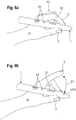
- Figures 5a and 5b show an exemplary movement sequence of a device for measuring and evaluating bradykinesia during a pronation-supination test.
- the device 1 is held in a hand H of the patient by means of a first grip G1 in such a way that the device 1 is as perpendicular as possible to the forearm.
- the rotational movement is generated by an alternating rotation of the hand H by rotating the forearm. At the end of the rotation, the ulna and radius are as parallel as possible next to each other. Such a movement approximates a rotation of the palm of the hand of 180 °. However, the rotation is not limited to 180 °, but can also be significantly less. As the patient gets older, mobility can be noticeably restricted. The maximum rotation can therefore be assumed, which the patient can perform. The patient repeats this sequence of movements over a defined measurement period T1 B.
- FIGS. 6a and 6b show an exemplary movement sequence of a tapping test.
- the device 1 is held by the hand H of a patient in a second grip G2.
- the index finger Z which initially rests on the reference point AP3, is then raised and stretched, as shown in FIG Figure 6b is shown, and then led back to the reference point AP3 until the index finger Z strikes the reference point AP3.
- a vibration of the device 1 is generated by the stop. This sequence of movements is carried out over a defined measurement period T1 T.
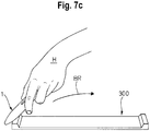
- FIGs 7a to 7c an exemplary movement sequence of a targeting test is shown.
- the device 1 is held in the hand H of a patient in a third grip G3 and is guided from one stop element 310 to the other, opposite stop element 320 of a test unit 300 by means of the hand H of the patient.
- the test unit 300 has two stop elements 310, 320 which are connected to one another by means of a connecting web 340.
- a contact surface 311, 312 is located on the surface of the stop elements 310, 320.
- a target point 315, 325 is present in the center of the contact surface 311, 321.
- the stop element 310, 320 can additionally be equipped with a proximity sensor, which detects how close the device 1 was moved to the target point 315, 325 at the time of the stop of the device 1 with the stop element 310, 320.
- the Figure 8a and 8b each show a flow chart of a measurement / evaluation process of the device 1.
- step S1 the push button 60 of the device 1 is actuated.
- step S2 it is then checked whether the charge of the battery 70 is sufficient for a measurement / evaluation process. If the charge of energy is not sufficient, the signal unit 90 outputs an acoustic signal of type 2 in step S3, an acoustic signal of type 2 being several tones following one another in rapid succession. The method then goes to step S6 and the device 1 is deactivated.
- step S4 If the charge of the battery 70 is sufficient for a measurement / evaluation process, the signal unit 90 does not emit an acoustic signal of type 2 and the patient can, in step S4, press the push button 60 for at least five seconds, i.e. for a long time, in order to advantageously transfer data via Bluetooth. Consequently, in step S5, evaluation data AD stored in the storage device 40 but not yet transmitted are exchanged via the wireless interface 80 with an external data processing device. The method then jumps to step S6 and the device 1 is deactivated.
- step S7 the evaluation data AD are transmitted in parallel via the wireless interface 80 to an external data processing device.
- step S7 the measurement procedure set via the slide control is recorded and there is a further waiting period of five seconds so that the patient has time to prepare to hold the device 1 in the measurement position as instructed. The process then continues with step S8.
- step S8 the signal unit 90 emits an acoustic signal of type 1, which indicates that the measurement is starting.
- the type 1 acoustic signal is characterized by the reproduction of a single tone. The process then continues with step S9.
- step S9 the acceleration sensor 20 records measurement data MD about the tremor.
- the acquisition of the measurement data MD takes a measurement duration T1 T , T1 B or T1 D of approx. 10, 30 and / or 60 seconds.
- the evaluation device 30 begins to evaluate measurement data MD that has already been recorded. The method jumps to step S10.
- step S10 it is checked whether the measurement period T1 has already expired. If the measurement period T1 has not yet expired, the method jumps to step S11.
- step S11 every 100 measurement data MD are filtered, that is to say windowed, by the evaluation device 30 by means of windowing. The method then proceeds to step S12.
- step S12 the 100 measurement data MD previously windowed in step S11 are Fourier transformed by the evaluation device 30. The method then jumps to step S13.
- step S13 For each partial result, a check is made in step S13 to determine whether a so-called overflow is present, that is to say whether a partial result appears so unrealistic that it is a measurement error that was probably caused by incorrect use of the device 1. Such a measurement error can occur through an unrealistically too high as well as an unrealistically too low partial result. If such an overflow occurs, the method jumps to step S14.
- step S14 the signal unit 90 outputs a type 2 acoustic signal. It is also determined that a measurement error has occurred, the measurement data MD are discarded, and the method jumps to step S6, in which the device 1 is deactivated.
- step S13 If no overflow occurs in step S13 and the measurement duration T1 has expired in step S10, the method jumps to step S16.
- step S16 the signal unit 90 emits an acoustic signal of type 1 and the acquisition of measurement data MD by the acceleration sensor 20 is ended. The method then jumps to step S 17.
- step S17 the evaluation device 30 determines various evaluation data AD for the evaluation period T2, such as the amplitude of the tremor, the frequency of the tremor and / or the energy content or the energy of the tremor. The method then jumps to step S18.
- step S18 it is checked whether the measurement and evaluation are OK. If an error appears realistic, the method jumps to step S14, an acoustic signal of type 2 is output, the measurement is discarded and the device 1 is deactivated in step S6. If the measurement and evaluation are found to be in order, the method jumps to step S19.
- step S19 of all the evaluation data AD, only a single parameter of the tremor, for example the amplitude, in the unit mg, the Frequency or the energy, in the unit mJ, is output by means of the display device 50 for a display period T3 of preferably approximately 30 seconds.
- the other evaluation data AD are not displayed.
- step S20 all evaluation data AD are stored in the storage device 40 in step S20.
- the method then jumps to step S6, and the device 1 is deactivated.
- ⁇ b> List of reference symbols ⁇ /b> 1 contraption 311 Contact area 10 casing 315 Target point 11 front section 320 Stop element 12th middle section 321 Contact area 13th rear section 325 Target point 14th Guide rail 340 Connecting bridge 15th Guide rail 350 Registration unit 16 opening 360 Display 17th opening 370 Luminous element 18th cover 380 speaker 19th deepening 20th Accelerometer AP1 first support point 25th Rotation rate sensor AP2 second support point 30th Evaluation facility AP3 Reference point 40 Storage facility H hand 50 Display device F. finger 60 Activation device Z index finger 70 battery D. thumb 80 wireless interface L.
Landscapes
- Health & Medical Sciences (AREA)
- Life Sciences & Earth Sciences (AREA)
- Physics & Mathematics (AREA)
- Heart & Thoracic Surgery (AREA)
- Molecular Biology (AREA)
- Veterinary Medicine (AREA)
- Biophysics (AREA)
- Pathology (AREA)
- Engineering & Computer Science (AREA)
- Biomedical Technology (AREA)
- Physiology (AREA)
- Medical Informatics (AREA)
- Public Health (AREA)
- Surgery (AREA)
- Animal Behavior & Ethology (AREA)
- General Health & Medical Sciences (AREA)
- Oral & Maxillofacial Surgery (AREA)
- Dentistry (AREA)
- Neurology (AREA)
- Neurosurgery (AREA)
- Developmental Disabilities (AREA)
- Geometry (AREA)
- Measurement Of The Respiration, Hearing Ability, Form, And Blood Characteristics Of Living Organisms (AREA)
Description
Die Erfindung betrifft eine Vorrichtung zum Erfassen und Auswerten von Tremor und Bradykinese im Hand- oder Armbereich eines Patienten, die bei der Benutzung in nur einer Hand des Patienten gehalten wird. Die Erfindung betrifft ferner ein Verfahren zum Erfassen, Auswerten von Tremor im Hand- oder Armbereich eines Patienten.The invention relates to a device for detecting and evaluating tremor and bradykinesia in the hand or arm area of a patient, which is held in only one hand of the patient during use. The invention also relates to a method for detecting and evaluating tremors in the hand or arm area of a patient.
Als Tremor wird das unwillkürliche, sich rhythmisch wiederholende Zusammenziehen einander entgegenwirkender Muskelgruppen bezeichnet. Es gibt verschiedene Arten von Tremor, die verschiedene Ursachen haben können. So wird beispielsweise unter anderem zwischen psychogenem Tremor, meist verursacht durch psychische Störungen, essentiellem Tremor, meist verursacht durch Gendefekte oder Parkinsontremor, verursacht durch die Parkinsonkrankheit, unterschieden.Tremor is the involuntary, rhythmically repetitive contraction of opposing muscle groups. There are different types of tremors that can have different causes. For example, a distinction is made between psychogenic tremor, mostly caused by mental disorders, essential tremor, mostly caused by genetic defects, and Parkinson's tremor, caused by Parkinson's disease.
Ein weiteres Symptom während des Frühstadiums der Parkinson-Krankheit ist die Bradykinese. Bradykinese betrifft alle Muskeln im Körper eines Menschen und verursacht eine Verlangsamung der Bewegungen, insbesondere gezielte Bewegungen, parallele motorische Abläufe und feinmotorische Tätigkeiten, und kann sich bis zu einer Bewegungslosigkeit, insbesondere Akinese genannt, führen. Die Krankheit äußert sich unter anderem durch ein zunehmend kleineres und unleserlich werdendes Schriftbild.Another symptom during the early stages of Parkinson's disease is bradykinesia. Bradykinesia affects all muscles in a person's body and causes a slowdown in movements, especially targeted movements, parallel motor processes and fine motor activities, and can lead to a lack of movement, in particular called akinesia. The disease manifests itself, among other things, by an increasingly smaller and illegible typeface.
Für einen Menschen ist es allerdings nahezu unmöglich die einzelnen Arten von Tremor nur durch menschliche Beobachtung zu unterscheiden. Um Fehldiagnosen zu vermeiden, wird versucht, anhand von sensorischen Messungen eine objektive Diagnostik, Quantifizierung oder Differenzierung zur Verfügung zu stellen, bei der die verschiedenen Arten des Tremors beziehungsweise deren Stärke erfasst werden können.For a human, however, it is almost impossible to distinguish the individual types of tremor just by human observation. In order to avoid misdiagnoses, attempts are made to use sensory measurements to provide objective diagnostics, quantification or differentiation in which the various types of tremor or their strength can be recorded.
Stand der Technik ist es unter anderem, Tremor mit Hilfe einer im Wesentlichen in Form eines Schreibgeräts ausgebildeten Vorrichtung zu erfassen, wie es
Allerdings muss der Computer mit einer entsprechenden Software ausgestattet sein und zum Auswerten der Daten von einem Fachmann mit Erfahrung in Technik und Diagnostik betrieben werden.However, the computer must be equipped with the appropriate software and be operated by a specialist with experience in technology and diagnostics in order to evaluate the data.
Weiterhin ist aus
Eine Vorrichtung, die bei der Diagnose von Nervenleiden, wie beispielsweise der Parkinsonschen Krankheit, Anwendung findet und als Schreibgerät ausgestaltet ist, beschreibt
Es ist bekannt, zum Erfassen und Auswerten von Tremor im Hand- oder Armbereich eines Patienten eine Vorrichtung zu benutzen, die in nur einer Hand des Patienten gehalten wird und die ein rohrförmiges Gehäuse, einen Beschleunigungssensor, eine Auswertungseinrichtung, ein Speichereinrichtung, eine Anzeigeeinheit und eine Aktivierungseinheit aufweist.It is known to use a device for detecting and evaluating tremor in the hand or arm area of a patient, which is held in only one hand of the patient and which has a tubular housing, an acceleration sensor, an evaluation device, a memory device, a display unit and a Has activation unit.
Der Erfindung liegt die Aufgabe zugrunde, eine Vorrichtung zum Erfassen, Auswerten und Differenzierung von Tremor und Bradykinese zu schaffen, mit der eine effiziente, objektive Diagnose oder Quantifizierung möglich ist.The invention is based on the object of creating a device for detecting, evaluating and differentiating tremor and bradykinesia, with which an efficient, objective diagnosis or quantification is possible.
Die Aufgabe wird durch eine Vorrichtung nach Anspruch 1 und ein Verfahren nach Anspruch 12 gelöst. Bevorzugte Ausgestaltungen der Erfindung sind Gegenstand der Ansprüche 2 bis 11 und 13 bis 15.The object is achieved by a device according to
Das rohrförmige Gehäuse erinnert an die Form eines Schreibgerätes, wodurch es für den Patienten intuitiv zu greifen ist.The tubular housing is reminiscent of the shape of a writing instrument, making it intuitive for the patient to grasp.
Für eine optimale Messung des Tremors wird die Vorrichtung locker in den Fingern eines Patienten gehalten. Durch das Abstützen der Vorrichtung an dem zweiten Abstützpunkt, wird das Halten der Vorrichtung an dem ersten Abstützpunkt unterstützt und beugt einem unnatürlichen Krafteinfluss durch die Griffkraft oder Verkrampfen der Finger vor.For optimal measurement of the tremor, the device is held loosely in a patient's fingers. By supporting the device on the second support point, the holding of the device at the first support point is supported and prevents an unnatural force influence from the grip force or cramping of the fingers.
Durch die integrierte Auswertungseinrichtung sind keine separate Auswertungseinrichtung oder sonstige weitere externe Komponenten nötig. Der Patient kann demnach auf einfache Weise selbst Messdaten aufnehmen, welche durch die Auswertungseinrichtung aufbereitet und ausgewertet werden. Ein technisch und/oder medizinisch versierter Fachmann ist somit in einem ersten Schritt nicht nötig. Für eine endgültige Diagnose oder Therapieentscheidung kann ein Arzt mit Hilfe der durch die Vorrichtung gemessenen und ausgewerteten Daten unterstützt werden.The integrated evaluation device means that no separate evaluation device or other additional external components are required. The patient can therefore easily record measurement data himself, which are processed and evaluated by the evaluation device. A technically and / or medically experienced specialist is therefore not necessary in the first step. For a final diagnosis or therapy decision, a doctor can be supported with the aid of the data measured and evaluated by the device.
Die Vorrichtung ist zweckmäßigerweise als sogenanntes "Handheld Device" ausgebildet, welches in einer Hand bedient werden kann.The device is expediently designed as a so-called "handheld device" which can be operated in one hand.
Die Aktivierungseinrichtung dient zusätzlich als Orientierungshilfe beim Ausrichten der Vorrichtung während des Messens. Beispielsweise ist die Vorrichtung während des Messens regelmäßig derart zu halten, dass die Aktivierungsvorrichtung nach oben zeigt. Auf diese Weise ist die Vorrichtung bei jeder Benutzung gleich ausgerichtet, was die Genauigkeit der Messungen erhöht.The activation device also serves as an orientation aid when aligning the device during the measurement. For example, the device is to be held regularly during the measurement in such a way that the activation device points upwards. In this way, the device is oriented the same every time it is used, which increases the accuracy of the measurements.
Erfindungsgemäß weist die Vorrichtung einen Drehratensensor auf und eignet sich damit zum Erfassen und Auswerten von Bradykinese. Der Drehratensensor ist in dem vorderen Abschnitt des Gehäuses angeordnet. Ferner ist der Drehratensensor durch die Aktivierungseinheit aktivierbar. In einer vorteilhaften Ausgestaltung dient die Batterie dazu, den Drehratensensor mit elektrischer Energie zu versorgen.According to the invention, the device has a rotation rate sensor and is therefore suitable for detecting and evaluating bradykinesia. The rotation rate sensor is arranged in the front section of the housing. Furthermore, the rotation rate sensor can be activated by the activation unit. In an advantageous embodiment, the battery serves to supply the rotation rate sensor with electrical energy.
Unter Drehratensensor ist ein Sensor zu verstehen, der die Rotationgeschwindigkeit um eine definierte Achse messen kann. Der Drehratensensor kann als Gyroskop oder als kapazitiver Drehratensensor ausgebildet sein. Vorteilhaft ist der Sensor derart ausgestaltet, dass Rotationsänderungen um drei orthogonal zueinander angeordnete Achsen erfasst werden. In Kombination mit dem Beschleunigungssensor, welcher vorzugsweise die lineare Beschleunigung in drei orthogonal zueinander angeordneten Richtungen misst, kann eine drei dimensionale Kinematik errechnet werden. Somit erfasst die erfindungsgemäße Vorrichtung sechs Freiheitsgrade. Je nach Anwendungsfall kann die erfindungsgemäße Vorrichtung neben dem Beschleunigungssensor einen Drehratensensor aufweisen, der die Rotation um nur eine Achse erfasst. Auf diese Weise verfügt die erfindungsgemäße Vorrichtung zwar nur über zwei Freiheitsgrade, stellt aber eine kompakte und kostengünstige Ausgestaltung sicher.A yaw rate sensor is to be understood as a sensor that can measure the speed of rotation about a defined axis. The rotation rate sensor can be designed as a gyroscope or as a capacitive rotation rate sensor. The sensor is advantageously designed in such a way that changes in rotation about three axes arranged orthogonally to one another are detected. In combination with the acceleration sensor, which is preferably the linear acceleration in three orthogonal to each other Measures directions, three-dimensional kinematics can be calculated. The device according to the invention thus covers six degrees of freedom. Depending on the application, the device according to the invention can have, in addition to the acceleration sensor, a rotation rate sensor that detects the rotation about only one axis. In this way, although the device according to the invention only has two degrees of freedom, it ensures a compact and inexpensive design.
Dadurch, dass der Drehratensensor in dem vorderen Bereich angeordnet ist, kann ein direkter Kraftfluss zwischen den Fingern und dem Drehratensensor stattfinden.Because the yaw rate sensor is arranged in the front area, a direct flow of force can take place between the fingers and the yaw rate sensor.
Des Weiteren besteht vorteilhafterweise die Möglichkeit, den Drehratensensor mittels der Aktivierungseinheit nur bei Bedarf zu aktivieren. Somit wird nur dann die Energie der Batterie verbraucht, die in einer vorteilhaften Ausgestaltung ebenfalls in dem Gehäuse angeordnet ist, wenn der Modus ausgewählt wird, der den Drehratensensor erfordert, wie insbesondere der Modus zum Messen der Bradykinese. Eine energiesparende Vorrichtung wird dadurch geschaffen.Furthermore, there is advantageously the possibility of activating the yaw rate sensor by means of the activation unit only when required. Thus, the energy of the battery, which is also arranged in the housing in an advantageous embodiment, is only consumed when the mode is selected which requires the rotation rate sensor, such as in particular the mode for measuring the bradykinesia. An energy-saving device is thereby created.
Der Beschleunigungssensor ist in dem vorderen Abschnitt angeordnet. Erfindungsgemäß sind der Beschleunigungssensor und der Drehratensensor in räumlicher Nähe zueinander angeordnet. Des Weiteren sind vorzugsweise der Beschleunigungssensor und der Drehratensensor auf einer zentralen Achse, die parallel zur Längsrichtung verläuft, angeordnet. Zweckmäßigerweise bilden der Beschleunigungssensor und der Drehratensensor eine räumliche Einheit.The acceleration sensor is arranged in the front portion. According to the invention, the acceleration sensor and the rotation rate sensor are arranged in spatial proximity to one another. Furthermore, the acceleration sensor and the yaw rate sensor are preferably arranged on a central axis which runs parallel to the longitudinal direction. The acceleration sensor and the rotation rate sensor expediently form a spatial unit.
Da der Beschleunigungssensor ebenfalls in dem vorderen Abschnitt angeordnet ist, ist der Weg zwischen Beschleunigungssensor und/oder Drehratensensor und den Fingern einer Hand auf diese Weise möglichst gering. Somit kann ein Impuls möglichst direkt an die Sensoren hin übertragen werden. Je direkter ein Impuls übertragen wird, den der Beschleunigungssensor und/oder Drehratensensor misst, desto geringer ist die Verzögerung und verfälscht die Messung. Die Qualität der Messdaten des Beschleunigungssensors und des Drehratensensors wird somit deutlich verbessert.Since the acceleration sensor is also arranged in the front section, the path between the acceleration sensor and / or rotation rate sensor and the fingers of one hand is as short as possible in this way. In this way, a pulse can be transmitted to the sensors as directly as possible. The more directly an impulse is transmitted, which the acceleration sensor and / or yaw rate sensor measures, the lower the delay and falsify the measurement. The quality of the measurement data from the acceleration sensor and the yaw rate sensor is thus significantly improved.
Zusätzlich können in einer weiteren Ausgestaltung Messfehler mittels einer räumlichen Nähe des Drehratensensors zu dem Beschleunigungssensor reduziert werden. Somit wird es ermöglicht, die Bewegung eines definierten Punktes sehr präzise zu bestimmen.In addition, in a further embodiment, measurement errors can be reduced by means of a spatial proximity of the rotation rate sensor to the acceleration sensor become. This enables the movement of a defined point to be determined very precisely.
Des Weiteren ist die zentrale Anordnung innerhalb des Gehäuses dahingehend vorteilhaft, dass unabhängig der rotierten Haltung der Vorrichtung um die Längsachse x die Sensoren vergleichbare Messwerte erfasst.Furthermore, the central arrangement within the housing is advantageous in that, regardless of the rotated position of the device about the longitudinal axis x, the sensors record comparable measured values.
Besonders vorteilhaft hat sich gezeigt, dass eine Anordnung des Drehratensensors und des Beschleunigungssensors als eine Einheit besonders exakt Messwerte erfassen kann. Eine Einheit ist dahingehend zu verstehen, dass die einzelnen Sensoren an einer Trägereinheit befestigt sind.It has been shown to be particularly advantageous that an arrangement of the rotation rate sensor and the acceleration sensor as a unit can record measured values particularly precisely. A unit is to be understood to mean that the individual sensors are attached to a carrier unit.
Durch die Verbesserung der Qualität der Messdaten des Beschleunigungssensors werden beispielsweise Daten von weiteren Sensoren, wie insbesondere Sensoren des Hautwiderstands oder Drucksensoren überflüssig. Je weniger Sensoren vorhanden sein müssen, desto kostengünstiger, kompakter lässt sich die Vorrichtung herstellen.By improving the quality of the measurement data from the acceleration sensor, for example, data from further sensors, such as in particular sensors for skin resistance or pressure sensors, become superfluous. The fewer sensors there have to be, the cheaper and more compact the device can be.
Die Vorrichtung weist einen Referenzpunkt für das dritte Fingerglied von wenigstens einem Finger der Hand des Patienten auf, der an dem Gehäuse angeordnet ist.The device has a reference point for the third phalanx of at least one finger of the patient's hand, which is arranged on the housing.
Der Referenzpunkt dient dazu, dem Patienten eine Hilfestellung zur Handhabung der Vorrichtung auf eine intuitive Weise zu vermitteln, sodass eine reproduzierbare Messdurchführung möglich wird. Aufgrund der Anordnung des Referenzpunkts an dem Gehäuse kann eine direkte Übertragung des Impulses zu den Sensoren sichergestellt werden. Es wäre denkbar, einen solchen Referenzpunkt auch mittels einer auf dem Gehäuse zusätzlich angebrachten Vorrichtung darzustellen.The reference point is used to provide the patient with assistance in handling the device in an intuitive manner, so that a reproducible measurement is possible. Due to the arrangement of the reference point on the housing, a direct transmission of the pulse to the sensors can be ensured. It would be conceivable to also represent such a reference point by means of a device additionally attached to the housing.
In einer kompakten Lösung ist der Referenzpunkt als eine Tippmulde vorgesehen. Somit wird ein haptisches, wahrnehmbares Merkmal geschaffen. Der Patient wird somit intuitiv darauf hingewiesen, dass beispielsweise diese Stelle bei einem Tapping-Test mit dem Zeigefinger angeschlagen werden soll. Ferner ist es denkbar, dass jeder Finger einer Hand, neben dem Zeigefinger, für einen solchen Tapping-Test verwendet werden kann.In a compact solution, the reference point is provided as a tip trough. This creates a haptic, perceptible feature. The patient is thus intuitively informed that, for example, this point should be struck with the index finger during a tapping test. It is also conceivable that each finger of a hand, in addition to the index finger, can be used for such a tapping test.
Vorteilhaft weist die Aktivierungseinrichtung einen Druckknopf und/oder Schieberegler auf. Zweckmäßigerweise hat die Aktivierungseinrichtung wenigstens eine der folgenden Einstellpositionen:
- Eine erste Einstellposition (0), die den Ausschaltzustand definiert;
- eine zweite Einstellposition (T), die einen Modus zur Messung von Tremor definiert;
- eine dritte Einstellposition (B), die einen Modus zur Messung von Bradykinese definiert, und
- eine vierte Einstellposition (D), die einen Modus zur differentialdiagnostischen Messung definiert.
- A first setting position (0) which defines the switch-off state;
- a second setting position (T) which defines a mode for measuring tremor;
- a third setting position (B) which defines a mode for measuring bradykinesia, and
- a fourth setting position (D) which defines a mode for differential diagnostic measurement.
Ein Druckknopf stellt die einfachste und bekannteste Ausgestaltung einer Aktivierungseinrichtung dar. Außerdem erleichtert das haptische Feedback des Druckknopfes die Bedienbarkeit der Vorrichtung. Durch den Schieberegler wird zusätzliche eine intuitive Einstellung des Messverfahrens ermöglicht. In Kombination mit einer Beschriftung der Einstellpositionen, ist es dem Patienten leicht verständlich zu vermitteln, in welchem Modus sich die Vorrichtung befindet. Bei einer Verwendung des Schiebereglers in Kombination mit einem Druckknopf, kann eine weitere Unterauswahl des durch den Schiebregler ausgewählten Modus vorgenommen werden. Dies bedeutet, dass zuerst mittels des Schiebereglers die zu untersuchende Symptomgruppe ausgewählt wird und mittels des Druckknopfs sowie ein mehrmaliges Betätigen des Druckknopfs ein Diagnoseverfahren ausgewählt wird. Ferner wäre es denkbar, dass die Aktivierungseinrichtung illuminiert ist, insbesondere mit einem roten und/oder grünen Licht, sodass dem Benutzer zusätzlich eine Information vermittelt wird.A push button represents the simplest and best-known embodiment of an activation device. In addition, the haptic feedback of the push button facilitates the operability of the device. The slider also enables the measurement method to be set intuitively. In combination with a labeling of the setting positions, it is easy to convey to the patient which mode the device is in. When using the slide control in combination with a push button, a further sub-selection of the mode selected by the slide control can be made. This means that the symptom group to be examined is first selected by means of the slide control and a diagnostic method is selected by means of the push button and pressing the push button several times. Furthermore, it would be conceivable that the activation device is illuminated, in particular with a red and / or green light, so that information is also conveyed to the user.
Vorteilhaft umfassen die Auswertungsdaten eine Amplitude des Tremors oder eine Frequenz des Tremors oder einen Energiegehalt des Tremors. In einer weiteren vorteilhaften Ausgestaltung umfassen die Auswertungsdaten ferner zumindest eines der folgenden Parameter: die Anzahl, die Intensität, die Änderung der Stärke und den Rhythmus von Tappings; wobei vorzugsweise die Auswertungsdaten ferner zumindest eines der folgenden Parameter umfassen: die Anzahl, die Intensität, die Änderung der Stärke und den Rhythmus von Änderungen der Rotationsrichtung; wobei vorzugsweise die Auswertungsdaten ferner zumindest eines der folgenden Parameter umfassen: die Anzahl, die Intensität, die Änderung der Stärke und den Rhythmus von Zieltreffern.The evaluation data advantageously include an amplitude of the tremor or a frequency of the tremor or an energy content of the tremor. In a further advantageous embodiment, the evaluation data also include at least one of the following parameters: the number, the intensity, the change in strength and the rhythm of tappings; wherein the evaluation data preferably further comprises at least one of the following parameters: the number, the intensity, the change in strength and the rhythm of changes in the direction of rotation; wherein preferably the evaluation data furthermore at least one of the following parameters include: the number, intensity, change in strength and rhythm of target hits.
Die Amplitude des Tremors stellt die Beschleunigung des Tremors in g-Kraft, insbesondere milli-g dar. Beispielsweise liegt das Grundzittern eines gesunden Menschen im Bereich von 3 milli-g, während bei einem Tremor die Amplitude im Bereich von 20 bis 300 milli-g liegt. Zusätzlich werden die Frequenz des Tremors und der Energiegehalt des Tremors ausgewertet. Aufgrund der vorliegenden Daten kann ein Hinweis auf die Art des Tremors gegeben werden.The amplitude of the tremor represents the acceleration of the tremor in g-force, in particular milli-g. For example, the basic tremor of a healthy person is in the range of 3 milli-g, while the amplitude of a tremor is in the range from 20 to 300 milli-g lies. In addition, the frequency of the tremor and the energy content of the tremor are evaluated. Based on the data available, an indication of the type of tremor can be given.
Zur Erfassung und Auswertung der Messdaten hinsichtlich Bradykinese wird zum einen eine Reihe an Taps, Pronations-Supinations-Bewegungen, die eine Änderung der Rotationsrichtung der Vorrichtung verursachen, und Zielbewegungen durchgeführt.To acquire and evaluate the measurement data with regard to bradykinesia, a series of taps, pronation-supination movements, which cause a change in the direction of rotation of the device, and target movements are carried out on the one hand.
Unter Tap, ist ein Anschlag eines Fingers an dem Gehäuse der Vorrichtung, wodurch eine messbare Erschütterung der Vorrichtung verursacht wird, zu verstehen. Folgend auch als Tapping-Test bezeichnet. Unter einer Folge an Pronation-Supinations-Bewegungen ist eine alternierende Drehung der Hand zu verstehen, die durch eine Rotation des Unterarms erzeugt wird, so dass möglichst Elle und Speiche nach der Drehung parallel, nebeneinander liegen. Folgend auch als Pronation-Supinations-Test bezeichnet. Unter Zielbewegungen ist eine Folge an koordinierten Bewegungen zu einem Zielpunkt hin zu verstehen, wobei die Vorrichtung an zwei definierte Punkte abwechselnd hingeführt wird. Folgend wird dies als Targeting-Test bezeichnet.A tap is to be understood as a stop of a finger on the housing of the device, as a result of which a measurable vibration of the device is caused. In the following also referred to as the tapping test. A sequence of pronation-supination movements is to be understood as an alternating rotation of the hand, which is generated by a rotation of the forearm, so that the ulna and radius are as parallel as possible after the rotation, next to each other. Also referred to below as the pronation-supination test. Target movements are to be understood as a sequence of coordinated movements towards a target point, the device being guided alternately to two defined points. This is referred to below as the targeting test.
Die Messdaten während eines Tapping-Tests, Pronation-Supinations-Test oder Targeting-Test umfassen die Anzahl, die Intensität, die Änderung der Stärke und den Rhythmus. Unter Anzahl ist eine dimensionslose Aufzählung an Bewegungsfolgen zu verstehen. Unter Intensität ist der durchschnittlich erfasste Messgröße der Beschleunigung in milli-g oder Rotationsgeschwindigkeit in °/sec zu verstehen. Unter Änderung der Stärke ist ein prozentueller Wert der Änderung der ersten zu der letzten Bewegungsfolge, erfasst in % zu verstehen, wobei 0 % eine gleichbleibende Amplitude und 100 % eine vollkommen unterschiedliche Amplitude beschreibt. Unter Rhythmus ist eine Reihe an Bewegungsfolgen zu verstehen, wobei die Zeit zwischen zwei folgenden Bewegungsfolgen verglichen werden. Dabei wird der Rhythmus mit einem Wert zwischen 0, vollkommen stochastisch, und 1, vollkommen gleichmäßig, in Schritten von 0,1 bewertet.The measurement data during a tapping test, pronation-supination test or targeting test include the number, the intensity, the change in strength and the rhythm. A number is to be understood as a dimensionless enumeration of sequences of movements. Intensity is to be understood as the average recorded measured variable of the acceleration in milli-g or the rotational speed in ° / sec. A change in strength is a percentage value of the change in the first to the last sequence of movements, recorded in%, with 0% describing a constant amplitude and 100% a completely different amplitude. A number of sequences of movements are allowed under rhythm understand, comparing the time between two following sequences of movements. The rhythm is rated with a value between 0, completely stochastic, and 1, completely even, in steps of 0.1.
Vorteilhaft umfasst die Vorrichtung eine Schnittstelle, vorzugsweise eine drahtlose Schnittstelle, zum Austauschen der Auswertungsdaten, zum Austauschen der Messdaten und/oder Rohdaten und/oder zum Austauschen von Einstellungen der Aktivierungseinrichtung mit einem externen Gerät.The device advantageously comprises an interface, preferably a wireless interface, for exchanging the evaluation data, for exchanging the measurement data and / or raw data and / or for exchanging settings of the activation device with an external device.
Die ausgewerteten Daten können auf der Vorrichtung gespeichert werden. Zweckmäßigerweise finden die Messung und Auswertung des Tremors über einen längeren Zeitraum, beispielsweise mehrere Wochen, statt. Die endgültige Diagnose und Art der Behandlung soll jedoch abschließend von einer medizinischen Fachkraft diagnostiziert werden. Durch die Schnittstelle, können die gemessenen und/oder ausgewerteten Daten an die medizinische Fachkraft übersendet werden, welche die Daten erneut evaluieren kann, was zu einer optimalen Diagnose und folglich zu einer optimalen Behandlung führt. Damit die Übertragung möglichst einfach und fließend in den Arbeitsalltag eines Arztes integrieren lässt, ist in einer vorteilhaften Ausgestaltung eine drahtlose Verbindung vorgesehen, die eine Vorrichtung mit einem Kabel zur Datenübertragung ersetzt.The evaluated data can be stored on the device. The measurement and evaluation of the tremor expediently take place over a longer period of time, for example several weeks. However, the final diagnosis and type of treatment should be final diagnosed by a healthcare professional. Through the interface, the measured and / or evaluated data can be sent to the medical specialist, who can reevaluate the data, which leads to an optimal diagnosis and consequently to an optimal treatment. So that the transmission can be integrated into the daily work of a doctor as simply and fluently as possible, a wireless connection is provided in an advantageous embodiment, which replaces a device with a cable for data transmission.
Ferner kann ein externes Gerät, ein mobiles Telefon oder ein Gerät eines Arztes umfassen. Mittels des Geräts des Arztes kann dieser eine Diagnose durchführen oder die erfassten Messdaten weiter verarbeiten, beziehungsweise in einer für den Patienten angelegten Patientenakte archivieren. Vorteilhaft ist es, dass durch die Übertragung der Messdaten, während der Messung, parallel die Messwerte angezeigt werden können. Des Weiteren kann eine Anpassung der Einstellung der Vorrichtung vorgenommen werden. Eine Kommunikation in beide Richtungen ermöglicht dies. Zweckmäßigerweise wird hierfür ein W-LAN oder Bluetooth Standard verwendet.Furthermore, an external device, a mobile telephone or a device of a doctor can include. Using the device of the doctor, the doctor can carry out a diagnosis or further process the recorded measurement data or archive it in a patient file created for the patient. It is advantageous that the measured values can be displayed in parallel through the transmission of the measured data during the measurement. Furthermore, the setting of the device can be adapted. This enables communication in both directions. A W-LAN or Bluetooth standard is expediently used for this.
Erfindungsgemäß umfasst die Vorrichtung eine Signaleinheit zum Ausgeben von zumindest akustischen oder haptisch wahrnehmbaren Signalen. Die Signaleinheit kann als ein Lautsprecher oder ein Vibrationsmotor ausgestaltet sein.According to the invention, the device comprises a signal unit for outputting at least acoustic or haptically perceptible signals. The signal unit can be designed as a loudspeaker or a vibration motor.
Um die Bedienbarkeit der Vorrichtung weiter zu verbessern und sie insbesondere intuitiver zu gestalten, gibt die Vorrichtung akustische oder haptisch wahrnehmbare Signale aus. Akustisches Feedback gibt dem Patienten eine Bestätigung für die korrekte Bedienung der Vorrichtung. Beispielsweise gibt die Signaleinheit, insbesondere ein Lautsprecher, ein akustisches Signal aus, wenn die Vorrichtung aktiviert und/oder deaktiviert wird, wenn die Messung beginnt und/oder endet und/oder wenn die Auswertung der gemessenen Daten beginnt und/oder endet. Denkbar (jedoch nicht beansprucht) ist es, dass die Signaleinheit ein optisch wahrnehmbares Signal abgibt.In order to further improve the operability of the device and, in particular, to make it more intuitive, the device emits acoustic or haptically perceptible signals. Acoustic feedback gives the patient confirmation that the device is being used correctly. For example, the signal unit, in particular a loudspeaker, emits an acoustic signal when the device is activated and / or deactivated, when the measurement begins and / or ends and / or when the evaluation of the measured data begins and / or ends. It is conceivable (but not claimed) that the signal unit emits a visually perceptible signal.
Zusätzlich kann die Signaleinheit eine bestimmte Reihenfolge von Signalen, insbesondere akustische, ausgeben, um beispielsweise Fehlercodes zu signalisieren, wie zum Beispiel einen niedrigen Ladezustand der Batterie, ein Fehler in der Messung oder Auswertung.In addition, the signal unit can output a specific sequence of signals, in particular acoustic signals, in order to signal error codes, for example, such as a low state of charge of the battery, an error in the measurement or evaluation.
Vorteilhaft weist das Gehäuse eine Länge zwischen 10 cm und 20 cm, insbesondere zwischen 14 cm und 17 cm, in der Längsrichtung auf und vorzugsweise einen Durchmesser zwischen 10 mm und 40 mm, insbesondere zwischen 15 mm und 30 mm auf, wobei vorzugsweise der vordere Abschnitt zwischen 10% und 60% der Länge aufweist, der mittlere Abschnitt zwischen 10% und 60% der Länge aufweist und der hintere Abschnitt zwischen 10% und 60% der Länge aufweist, wobei ferner vorzugsweise das Gehäuse zumindest in dem vorderen Abschnitt sich in der Längsrichtung konisch verjüngend ausgestaltet ist. Die Abmessungen des Gehäuses der Vorrichtung sind entsprechend der Anwendung optimiert. Die Länge des Gehäuses ist mindestens so lang, dass es bei üblichen Handgrößen möglich ist, das dritte Fingerglied (Phalanx distalis) von wenigstens einem Finger der Hand des Patienten an dem ersten Abstützpunkt abzustützen und der zweite Abstützpunkt in dem Zwischenraum zwischen Daumen und Zeigefinger der Hand des Patienten abstützt. Ist die Länge des Gehäuses allerdings zu groß, verlagert sich der Schwerpunkt der Vorrichtung weg von dem ersten und zweiten Abstützpunkt. Dieser Effekt hat durch seine Hebelwirkung zu dem ersten und zweiten Abstützpunkt eine erhebliche negative Auswirkung auf die Qualität der Messung. Am bevorzugtesten hat sich eine Länge von 16 cm herausgestellt.The housing advantageously has a length between 10 cm and 20 cm, in particular between 14 cm and 17 cm, in the longitudinal direction and preferably a diameter between 10 mm and 40 mm, in particular between 15 mm and 30 mm, with the front section preferably between 10% and 60% of the length, the middle section between 10% and 60% of the length and the rear section between 10% and 60% of the length, further preferably the housing at least in the front section extending in the longitudinal direction is designed to taper conically. The dimensions of the housing of the device are optimized according to the application. The length of the housing is at least so long that it is possible with normal hand sizes to support the third phalanx (phalanx distalis) by at least one finger of the patient's hand at the first support point and the second support point in the space between the thumb and forefinger of the hand of the patient. However, if the length of the housing is too great, the center of gravity of the device shifts away from the first and second support points. Due to its leverage to the first and second support points, this effect has a considerable negative effect on the quality of the measurement. A length of 16 cm has been found to be most preferred.
Das Gehäuse weist einen Durchmesser auf, der für eine übliche Fingergröße eines Patienten gut greifbar ist. Allerdings haben Patienten, welche die Vorrichtung benutzen, häufig feinmotorische Einschränkungen. Der Durchmesser des Gehäuses ist deshalb groß genug, dass Patienten mit feinmotorischen Einschränkungen das Gehäuse sicher greifen können.The housing has a diameter that is easy to grasp for a patient's usual finger size. However, patients using the device often have fine motor impairments. The diameter of the housing is therefore large enough that patients with fine motor impairments can safely grip the housing.
Das Gehäuse der Vorrichtung verjüngt sich in dem vorderen Abschnitt in der Längsrichtung. Die Form des Gehäuses erinnert dadurch der Form eines üblichen Schreibgeräts und erlaubt es dem Patienten intuitiv wahrzunehmen, wie die Vorrichtung zu halten ist. Am bevorzugtesten hat sich ein Durchmesser von 20 mm herausgestellt.The housing of the device tapers in the front section in the longitudinal direction. The shape of the housing is reminiscent of the shape of a conventional writing instrument and allows the patient to intuitively perceive how the device is to be held. A diameter of 20 mm has been found to be most preferred.
Der vordere, mittlere und hintere Abschnitt muss nicht gleichmäßig auf die Länge der Vorrichtung verteilt sein. Je nach Ausgestaltung kann jeder der Abschnitte 10% bis 60% der Länge der Vorrichtung aufweisen.The front, middle and rear sections need not be evenly distributed along the length of the device. Depending on the configuration, each of the sections can have 10% to 60% of the length of the device.
Vorteilhaft umfasst die Vorrichtung wenigstens eine Platine, auf welcher der Beschleunigungssensor, der Drehratensensor, die Auswertungseinrichtung, die Speichereinrichtung, die Anzeigeeinrichtung, die Aktivierungseinrichtung, die Batterie, die drahtlose Schnittstelle und/oder die Signaleinheit angeordnet sind, wobei vorzugsweise die Platine formschlüssig und/oder kraftschlüssig in dem Gehäuse gehalten ist und wobei vorzugsweise das Gehäuse wenigstens eine Führungsschiene zum Aufnehmen der Platine aufweist. Ferner sind vorzugsweise der Beschleunigungssensor und der Drehratensensor auf der Platine nebeneinander angeordnet.The device advantageously comprises at least one circuit board on which the acceleration sensor, the rotation rate sensor, the evaluation device, the storage device, the display device, the activation device, the battery, the wireless interface and / or the signal unit are arranged, with the circuit board preferably being positively and / or is held non-positively in the housing and wherein the housing preferably has at least one guide rail for receiving the circuit board. Furthermore, the acceleration sensor and the yaw rate sensor are preferably arranged next to one another on the board.
Die Anordnung des Beschleunigungssensors, des Drehratensensors der Auswertungseinrichtung, der Speichereinrichtung und/oder der Batterie auf einer Platine vereinfacht die Kommunikation unter den einzelnen Elementen. Damit eine möglichst optimale Messung durch den Beschleunigungssensor oder den Drehratensensor sichergestellt wird, ist die Platine formschlüssig und/oder kraftschlüssig in dem Gehäuse gehalten. Eine besondere bevorzugte Methode ist das Vorsehen einer Führungsschiene zum Aufnehmen der Platine in dem Gehäuse. Nach dem Herstellen des Gehäuses kann die Platine über die Führungsschiene einfach in das Gehäuse geschoben werden. Anschließend wird die Platine mit der Führungsschiene formschlüssig und/oder kraftschlüssig verbunden, um einen sicheren Halt zu gewährleisten. Es wäre denkbar in einer weiteren Ausgestaltung den Drehratensensor und den Beschleunigungssensor auf zwei separate Platinen anzuordnen.The arrangement of the acceleration sensor, the rotation rate sensor of the evaluation device, the storage device and / or the battery on a circuit board simplifies communication between the individual elements. In order to ensure the best possible measurement by the acceleration sensor or the yaw rate sensor, the circuit board is held in the housing in a form-fitting and / or force-fitting manner. A particularly preferred method is to provide a guide rail for receiving the circuit board in the housing. After the housing has been manufactured, the circuit board can simply be pushed into the housing via the guide rail. Then will the board with the guide rail positively and / or non-positively connected to ensure a secure hold. In a further embodiment, it would be conceivable to arrange the rotation rate sensor and the acceleration sensor on two separate circuit boards.
Vorteilhaft sind die Anzeigeeinrichtung in dem mittleren Abschnitt und vorzugsweise die Batterie in dem hinteren Abschnitt angeordnet, wobei ferner vorzugsweise das Gehäuse mit wenigstens einer Öffnung zur Aufnahme der Anzeigeeinrichtung, der Aktivierungseinrichtung und/oder des Lautsprechers versehen ist.The display device is advantageously arranged in the middle section and preferably the battery in the rear section, the housing also preferably being provided with at least one opening for receiving the display device, the activation device and / or the loudspeaker.
Zweckmäßigerweise kann auch die Anzeigeeinrichtung, die Aktivierungseinrichtung und/oder der Lautsprecher direkt an dem Gehäuse angeordnet sein und durch eine Verbindung, insbesondere eine Kabelverbindung, mit der Platine im inneren der Vorrichtung verbunden sein. In diesem Fall ist für das jeweilige Element keine Öffnung im Gehäuse notwendig.The display device, the activation device and / or the loudspeaker can expediently also be arranged directly on the housing and be connected to the circuit board in the interior of the device by a connection, in particular a cable connection. In this case, no opening in the housing is necessary for the respective element.
Die Anzeigeeinrichtung kann zweckmäßigerweise auch während des Messvorgangs einsehbar sein. Der mittlere Abschnitt der Vorrichtung ist während des Messvorgangs kaum durch die Hand und nicht durch Finger des Patienten verdeckt. Das Anordnen der Anzeigeeinrichtung im mittleren Abschnitt ermöglicht es dem Patienten somit auch während des Messvorgangs die darauf angezeigten Daten einzusehen. Obwohl es naheliegt, die Aktivierungseinrichtung und die Anzeigeeinrichtung nebeneinander anzuordnen, kann die Anzeigeeinrichtung auch auf dem Gehäuse versetzt angeordnet werden, sodass bei Bedienung der Vorrichtung während des Messvorgangs die Aktivierungseinrichtung zur Ausrichtung der Vorrichtung nach oben zeigt und die Anzeigeeinrichtung derart versetzt ist, dass der Patient diese in einem geradem Winkel einsehen kann.The display device can expediently also be visible during the measurement process. The middle section of the device is hardly covered by the hand and not by the patient's fingers during the measurement process. Arranging the display device in the middle section enables the patient to see the data displayed on it even during the measurement process. Although it is obvious to arrange the activation device and the display device next to one another, the display device can also be arranged offset on the housing, so that when the device is operated during the measurement process, the activation device for aligning the device points upwards and the display device is offset in such a way that the patient can see this at a straight angle.
Die Batterie weist ein hohes Gewicht im Vergleich zu den weiteren Komponenten der Vorrichtung auf. Deshalb ist es vorteilhaft die Batterie in dem hinteren Abschnitt anzuordnen. Dort unterstützt das Gewicht der Batterie das Abstützen der Vorrichtung am zweiten Abstützpunkt an dem Zwischenraum zwischen Daumen und Zeigefinger der Hand des Patienten.The battery has a high weight compared to the other components of the device. It is therefore advantageous to arrange the battery in the rear section. There, the weight of the battery supports the support of the device at the second support point at the space between the thumb and forefinger of the patient's hand.
Vorteilhaft weist das Gehäuse einen abnehmbaren Deckel zum Einlegen der Batterie auf, wobei zweckmäßigerweise die Platine durch den Deckel in dem Gehäuse eingespannt ist.The housing advantageously has a removable cover for inserting the battery, the circuit board expediently being clamped in the housing by the cover.
Vorteilhaft besteht das Gehäuse aus Kunststoff, insbesondere Polykarbonat.Kunststoff ermöglicht es dem Gehäuse eine bevorzugte Mischung aus Stabilität und Gewicht zu erreichen. Ein bevorzugtes Gewicht des Gehäuses beträgt 35 Gramm.The housing is advantageously made of plastic, in particular polycarbonate. Plastic enables the housing to achieve a preferred mixture of stability and weight. A preferred weight of the housing is 35 grams.
Vorteilhafterweise befindet sich ein Schwerpunkt in dem mittleren Abschnitt.Eine verbesserte Handhabung der Vorrichtung wird somit geschaffen. Dabei befindet sich der Schwerpunkt der Vorrichtung in einer vorteilhaften Ausgestaltung in der Nähe des zweiten Abstützpunkts. Die Haltung der stiftähnlichen Vorrichtung liegt somit besonders vorteilhaft und ausbalanciert in der Hand des Patienten. Somit ruht die Vorrichtung auf dem zweiten Abstützpunkt und der Patient benötigt weniger Kraft in den Fingern um die Vorrichtung fest zu halten.A center of gravity is advantageously located in the middle section. Improved handling of the device is thus created. In an advantageous embodiment, the center of gravity of the device is located in the vicinity of the second support point. The posture of the pen-like device is therefore particularly advantageous and balanced in the patient's hand. Thus, the device rests on the second support point and the patient needs less force in the fingers to hold the device firmly.
Vorteilhaft weist der Beschleunigungssensor und/oder der Drehratensensor eine Abtastrate von jeweils mindestens 50 Hz, oder vorzugsweise mindestens 100 Hz oder am bevorzugtesten mindestens 200 Hz auf.The acceleration sensor and / or the rotation rate sensor advantageously has a sampling rate of at least 50 Hz, or preferably at least 100 Hz, or most preferably at least 200 Hz.
Mittels einer Abtastrate von mindestens 50 Hz ist es möglich, den Tapping-Tests, den Pronation- und Supinations- Tests und den Targeting -Tests durchzuführen. Mittels den dabei erfassten Daten wird eine Wahrscheinlichkeit über eine mögliche Erkrankung an Bradykinese diagnostiziert. Eine Abtastrate von mindestens 100 Hz des Beschleunigungssensors ermöglicht eine Diagnose über die Wahrscheinlichkeit einer Erkrankung an Tremor zu diagnostizieren. Eine Abtastrate von mindestens 200 Hz hingegen ermöglicht die Durchführung der Differentialdiagnose von Tremor. Die Abtastrate ist dahingehend ein wesentlicher Bestandteil, dass der Aliasing-Effekt reduziert oder sogar ausgeschlossen werden kann.With a sampling rate of at least 50 Hz it is possible to carry out the tapping tests, the pronation and supination tests and the targeting tests. The data recorded in this way is used to diagnose a likelihood of a possible disease of bradykinesia. A sampling rate of at least 100 Hz of the acceleration sensor enables a diagnosis to be made about the likelihood of a disease from tremor. A sampling rate of at least 200 Hz, on the other hand, enables the differential diagnosis of tremor to be carried out. The sampling rate is an essential component in that the aliasing effect can be reduced or even eliminated.
In einer Vorteilhaften Ausgestaltung weist die Vorrichtung eine zusätzliche Testeinheit zum Durchführen eines Targeting-Tests auf, welche wenigstens zwei Anschlagelemente aufweist, die in einem vorgegebenen Abstand zueinander angeordnet sind; wobei die Anschlagelemente jeweils eine Kontaktfläche aufweisen, die geeignet ist, durch den vorderen Abschnitt bei einem Anschlag der Vorrichtung an das Anschlagelement kontaktiert zu werden.In an advantageous embodiment, the device has an additional test unit for carrying out a targeting test, which has at least two stop elements which are arranged at a predetermined distance from one another; wherein the stop elements each have a contact surface have which is suitable to be contacted by the front portion when the device strikes the stop element.
Mittels der zusätzlichen Einheit wird dem Patienten eine Hilfestellung in der Durchführung eines Targeting-Tests gegeben. Dabei wird es ermöglicht, dem Patienten einen gleichbleibenden, vergleichbaren Bewegungsablauf vorzugeben, indem sich das zu treffende Ziel in einem vorgegeben, konstantem Abstand zueinander befindet. Die Anschlagelemente können ferner dämpfende Elemente aufweisen und würden somit einen weicheren Anschlag schaffen, der zum einen schonend für das Gerät und zugleich für die Gelenke des Patienten ist.The additional unit provides the patient with assistance in carrying out a targeting test. This makes it possible to specify a constant, comparable sequence of movements for the patient, in that the target to be hit is at a predetermined, constant distance from one another. The stop elements can also have damping elements and would thus create a softer stop that is gentle on the device and on the patient's joints at the same time.
Ferner werden gleichbleibende Rahmenbedingungen für alle Patienten geschaffen, sodass diese untereinander verglichen werden können.Furthermore, constant framework conditions are created for all patients so that they can be compared with one another.
In einer weiteren Vorteilhaften Ausgestaltung weist die Testeinheit einen Zielpunkt auf, der sich auf der Kontaktfläche befindet. Zweckmäßigerweise ist der Zielpunkt im Wesentlichen in der Mitte der Kontaktfläche angeordnet.In a further advantageous embodiment, the test unit has a target point that is located on the contact surface. The target point is expediently arranged essentially in the center of the contact surface.
Der Zielpunkt ermöglicht eine leicht erkennbare und intuitive Orientierung für den Patienten. Der Zielpunkt definiert einen Bereich auf der Kontaktfläche durch eine Kennzeichnung. Diese Kennzeichnung kann in einer möglichen Ausgestaltung ein bunter Kreis sein oder eine Kerbe. Dadurch dass der Zielpunkt im Wesentlichen in der Mitte der Kontaktfläche ist, wird der Patient mit einer höheren Wahrscheinlichkeit die Kontaktfläche treffen. Durch eine solche Ausführungsform kann die Durchführung eines Targeting-Tests dem Patienten leicht und verständlich vermittelt werden.The target point enables an easily recognizable and intuitive orientation for the patient. The target point defines an area on the contact surface by means of a marking. In one possible embodiment, this identification can be a colored circle or a notch. Because the target point is essentially in the center of the contact area, the patient is more likely to hit the contact area. By means of such an embodiment, the implementation of a targeting test can be conveyed to the patient in an easy and understandable manner.
Vorteilhaft ist der Abstand zwischen den Anschlagelementen verstellbar; wobei vorzugsweise der Abstand zwischen den Anschlagelementen zwischen 5 cm und 100 cm, bevorzugt zwischen 10 cm und 50 cm, am bevorzugtesten zwischen 15 cm und 25 cm beträgt.The distance between the stop elements is advantageously adjustable; wherein the distance between the stop elements is preferably between 5 cm and 100 cm, preferably between 10 cm and 50 cm, most preferably between 15 cm and 25 cm.
Dadurch dass der Abstand zwischen den Anschlagelementen verstellbar ist, ist eine individuelle Anpassung möglich. Der Abstand wird zwischen den Zielpunkten gemessen. Beispielsweise kann für ein Kind ein anderer Abstand eingestellt werden als für einen Erwachsenen oder für einen Patienten der nur beschränkt Bewegungen durchführen kann. Generell hat sich jedoch gezeigt, dass ein Abstand von ca. 20 cm besonders vorteilhaft für die Durchführung eines Targeting-Tests ist.Because the distance between the stop elements can be adjusted, an individual adjustment is possible. The distance is measured between the target points. For example, a different distance can be set for a child than for an adult or for a patient who is only limited Can perform movements. In general, however, it has been shown that a distance of approx. 20 cm is particularly advantageous for carrying out a targeting test.
Vorteilhaft weist die Testeinheit einen Verbindungssteg auf, der die Anschlagelemente miteinander verbindet; wobei vorzugsweise der Abstand zwischen den Anschlagelementen durch den Verbindungssteg verstellbar ist.The test unit advantageously has a connecting web which connects the stop elements to one another; wherein the distance between the stop elements is preferably adjustable by the connecting web.
Mittels des Verbindungsstegs kann während eines Targeting-Tests ein konstanter und gleichbleibender Abstand gewährleistet werden. Dadurch, dass dieser verstellbar ist, kann eine einfachere und kompaktere Handhabung der Einheit geschaffen werden, aber auch eine Anpassung an die Bedürfnisse unterschiedlicher Patienten. Die Verstellung kann teleskopartig erfolgen.By means of the connecting web, a constant and constant distance can be guaranteed during a targeting test. Because this is adjustable, a simpler and more compact handling of the unit can be created, but also an adaptation to the needs of different patients. The adjustment can be done telescopically.
Vorteilhaft weist die Testeinheit eine Erfassungseinheit auf, durch die zumindest einer der folgenden Parameter erfasst wird: die Anzahl an Anschlägen, die Zeit zwischen zwei Anschlägen und die Gesamtdauer des Tests; wobei vorzugsweise der erfasste Parameter mittels eines Displays anzeigbar ist; wobei vorzugsweise das Display an dem Verbindungssteg angeordnet ist.The test unit advantageously has a detection unit by means of which at least one of the following parameters is detected: the number of attacks, the time between two attacks and the total duration of the test; wherein the detected parameter can preferably be shown by means of a display; wherein the display is preferably arranged on the connecting web.
Die Erfassungseinheit ist in einer weiteren voreilhaften Ausgestaltung mit der Vorrichtung mittels einer drahtlosen Verbindung koppelbar. Die Erfassungseinheit dient dazu, Vorgänge und Bewegungsfolgen zu erfassen, die anschließend mittels des Displays angezeigt werden kann. Dadurch wird dem Patienten die erfasste Information direkt vermittelt.In a further advantageous embodiment, the detection unit can be coupled to the device by means of a wireless connection. The acquisition unit is used to record processes and sequences of movements, which can then be shown by means of the display. In this way, the recorded information is conveyed directly to the patient.
Vorteilhaft weist die Testeinheit eine Signaleinheit auf, die geeignet ist, bei einem Anschlag der Vorrichtung an einem der Anschlagelemente ein Signal zu erzeugen; wobei vorzugsweise die Signaleinheit als Leuchtelement insbesondere als LED, oder als Lautsprecher ausgestaltet ist.The test unit advantageously has a signal unit which is suitable for generating a signal when the device hits one of the stop elements; wherein the signal unit is preferably designed as a lighting element, in particular as an LED, or as a loudspeaker.
Die Signaleinheit kann insbesondere ein Lautsprecher, ein Leuchtelement oder ein Vibrationsmotor umfassen. Mittels der Signaleinheit kann dem Patienten das Feedback vermittelt werden, ob dieser mit der Vorrichtung einen Kontakt mit der Einheit hergestellt hat. Dadurch kann dem Patienten angezeigt werden, ob dieser mit der Vorrichtung ausreichend weit die vorgegebene Bewegung durchgeführt hat und kann somit dem Patienten eine Hilfestellung zur Selbstkontrolle geben.The signal unit can in particular comprise a loudspeaker, a light element or a vibration motor. The signal unit can be used to convey feedback to the patient as to whether the device has made contact with the unit. This allows the patient to be shown whether this has carried out the specified movement sufficiently far with the device and can thus provide the patient with assistance in self-control.
Die Erfindung beinhaltet ein Verfahren nach Anspruch 12.The invention includes a method according to
Das Verfahren zeichnet sich durch seine intuitive Führung des Patienten durch die einzelnen Verfahrensschritte aus. Zudem bietet das Verfahren eine kompakte, zeiteffiziente Möglichkeit den Tremor eines Patienten zu messen und autark auszuwerten. Für den Patienten entspricht die Komplexität der Anwendung der Vorrichtung und des Verfahrens in etwa der Komplexität der Anwendung eines üblichen Fieberthermometers.The procedure is characterized by its intuitive guidance of the patient through the individual procedural steps. In addition, the method offers a compact, time-efficient option to measure a patient's tremor and evaluate it independently. For the patient, the complexity of using the device and the method roughly corresponds to the complexity of using a conventional clinical thermometer.
Das Verfahren ermöglicht eine autarke Messung und Auswertung des Tremors eines Patienten. Externe Komponenten sind somit nicht nötig.The procedure enables a self-sufficient measurement and evaluation of a patient's tremor. External components are therefore not necessary.
Außerdem wird der Patient nicht gezwungen die Vorrichtung während der Messung zu bewegen. Ein Zeichnen von Formen, wie es bei bekannten Messverfahren eines Tremors üblich ist, entfällt. Der Patient muss während der Messdauer die Vorrichtung lediglich entspannt und unbelastet in der vorgesehenen Position halten.In addition, the patient is not forced to move the device during the measurement. There is no need to draw shapes, as is customary with known tremor measurement methods. The patient only has to hold the device relaxed and unloaded in the intended position during the measurement period.
Vorteilhaft beträgt die Messdauer weniger als 60 Sekunden, insbesondere weniger als 40 Sekunden. In der Praxis hat sich eine Messdauer von ca. 30 Sekunden als besonders geeignet herausgestellt. Vorzugsweise beträgt die Auswertungsdauer weniger als 10 Sekunden. Die Anzeigedauer beträgt erfindungsgemäß wenigstens 20 Sekunden, insbesondere mehr als 45 Sekunden. Eine Anzeigedauer von ca. 30 Sekunden hat sich jedoch in vielen Fällen als besonders praxisgerecht herausgestellt.The measurement duration is advantageously less than 60 seconds, in particular less than 40 seconds. In practice, a measurement duration of approx. 30 seconds has proven to be particularly suitable. The evaluation time is preferably less than 10 seconds. According to the invention, the display duration is at least 20 seconds, in particular more than 45 seconds. However, a display time of approx. 30 seconds has proven to be particularly practical in many cases.
Der gesamte Mess-, Auswerte- und Anzeigevorgang hält somit einen überschaubaren zeitlichen Rahmen ein. Die Messdauer und die Auswertungsdauer sollen so kurz wie möglich sein, jedoch ist eine gewisse Messdauer für ein belastbares Messergebnis nötig, da die Auswertungsdauer abhängig von der Rechenleistung der Auswertungseinrichtung und der Komplexität der auszuwertenden Daten ist. Die Anzeigedauer kann je nach Präferenz eingestellt werden.The entire measurement, evaluation and display process thus adheres to a manageable time frame. The measurement duration and the evaluation duration should be as short as possible, but a certain measurement duration is necessary for a reliable measurement result, since the evaluation duration depends on the computing power of the evaluation device and the complexity of the data to be evaluated. The display duration can be set according to your preference.
Ein (nicht under die Ansprüche fallendes) Verfahren zum Erfassen und Auswerten von Bradykinese im Hand- oder Armbereich eines Patienten mit Hilfe einer der oben genannten Vorrichtung umfasst die Schritte.
- Aktivieren der Vorrichtung mittels der Aktivierungseinrichtung zum Messen von Bradykinese;
- Halten der Vorrichtung mit einem vorgegebenen Griff der Hand des Patienten;
- Ausführen einer ersten Bewegungsfolge;
- Messen von Messdaten über die Bradykinese mittels des Beschleunigungssensors und des Drehratensensors während einer bestimmten Messdauer;
- Auswerten der Messdaten und Bereitstellen von Auswertungsdaten mittels der Auswertungseinrichtung während einer vorbestimmten Auswertungsdauer;
- Speichern der Messdaten oder der Auswertungsdaten mittels der Speichereinrichtung;
- Anzeigen der Auswertungsdaten mittels der Anzeigeeinrichtung für eine vorbestimmte Anzeigedauer und
- Deaktivieren der Vorrichtung nach Ablauf der Anzeigedauer.
- Activating the device by means of the activation device for measuring bradykinesia;
- Holding the device with a predetermined grip of the patient's hand;
- Performing a first sequence of movements;
- Measurement of measurement data via bradykinesia by means of the acceleration sensor and the rotation rate sensor during a specific measurement period;
- Evaluating the measurement data and providing evaluation data by means of the evaluation device during a predetermined evaluation period;
- Storing the measurement data or the evaluation data by means of the memory device;
- Displaying the evaluation data by means of the display device for a predetermined display duration and
- Deactivating the device after the display time has elapsed.
Vorteilhaft weist das Verfahren eine erste Bewegungsfolge auf, bei der alternierende Pronations- und Supinations-Bewegungen ausgeführt werden; wobei vorzugsweise hierbei die Vorrichtung mit der Hand des Patienten in einer ersten Haltung des Griffs fest ergriffen wird.The method advantageously has a first sequence of movements in which alternating pronation and supination movements are carried out; wherein the device is preferably firmly gripped with the patient's hand in a first position of the handle.
Die erste Haltung der Hand bildet einen ersten Griff, der eine faustartige Umschließung der Vorrichtung umfasst. Dadurch wird eine Haltung der Vorrichtung, die im Wesentlichen im Lot zum Unterarm ist, geschaffen. Die rotierende Bewegung der Messvorrichtung kann dadurch besonders gut erfasst werden. Denkbar wäre es auch einen anderen Griff zu verwenden, wobei die Vorrichtung fest in einer konstanten Position zur Hand positioniert wird. Dabei wird die Pronation-Supinations Bewegung erfasst.The first position of the hand forms a first handle which comprises a fist-like enclosure of the device. This creates a posture for the device that is essentially perpendicular to the forearm. The rotating movement of the measuring device can thereby be recorded particularly well. It would also be conceivable to use a different handle, the device being firmly positioned in a constant position at hand. The pronation-supination movement is recorded.
Vorteilhaft weist das Verfahren eine zweite Bewegungsfolge auf, bei der Tippbewegungen eines Fingers der Hand des Patienten auf den Referenzpunkt ausgeführt werden; wobei vorzugsweise hierbei die Vorrichtung mit der Hand des Patienten in einer zweiten Haltung des Griffs so ergriffen wird, dass das dritte Fingerglied von wenigstens einem Finger der Hand des Patienten an dem wenigstens einen ersten Abstützpunkt, den das Gehäuse bildet, und der hintere Abschnitt des Gehäuses in dem Zwischenraum zwischen Daumen und Zeigefinger der Hand des Patienten an dem wenigstens einen zweiten Abstützpunkt, den das Gehäuse bildet, abgestützt wird.The method advantageously has a second sequence of movements in which tapping movements of a finger of the patient's hand are performed on the reference point; preferably in this case the device is gripped with the patient's hand in a second position of the handle so that the third phalanx of at least one finger of the patient's hand is at the at least one first support point formed by the housing and the rear section of the housing is supported in the space between the thumb and forefinger of the patient's hand at the at least one second support point which the housing forms.
Die zweite Haltung einer Hand bildet einen zweiten Griff, welcher die Vorrichtung derart hält, dass der Tapping-Test durchgeführt werden kann. Hierbei wird die Vorrichtung durch einen Finger, insbesondere dem Zeigefinger, erschüttert. Dadurch kann eine Beschleunigung, die dadurch verursacht wird, gemessen werden.The second position of one hand forms a second grip which holds the device in such a way that the tapping test can be carried out. In this case, the device is shaken by a finger, in particular the index finger. This allows an acceleration caused thereby to be measured.
In vorteilhafter Weise weist das Verfahren eine dritte Bewegungsfolge auf, bei der Hin- und Herbewegungen der Hand des Patienten zwischen zwei vorgegebenen Zielpunkten ausgeführt werden; wobei vorzugsweise hierbei die Vorrichtung mit der Hand des Patienten in einer dritten Haltung des Griffs fest ergriffen wird. Durch den dritten Griff der Vorrichtung kann der Patient den vorderen Abschnitt der Vorrichtung koordiniert führen.The method advantageously has a third sequence of movements in which the patient's hand is moved back and forth between two predetermined target points; preferably in this case the device is firmly gripped with the patient's hand in a third position of the handle. The third handle of the device enables the patient to guide the front section of the device in a coordinated manner.
Vorteilhaft stehen dem Verfahren Zielpunkte zur Verfügung, die durch eine oben beschriebene Testeinheit bereitgestellt werden.The method advantageously has target points available that are provided by a test unit described above.
Dem Patienten kann durch eine solche Testeinheit das Verfahren besonders intuitiv und leicht vermittelt werden.The method can be conveyed to the patient particularly intuitively and easily by means of such a test unit.
Vorteilhaft beträgt die Messdauer weniger als 60 Sekunden, insbesondere weniger als 30 Sekunden, bevorzugt ca. 10 Sekunden, wobei vorzugsweise die Auswertungsdauer weniger als 10 Sekunden beträgt, und wobei vorzugsweise die Anzeigedauer wenigstens 20 Sekunden, insbesondere mehr als 45 Sekunden, beträgt.The measurement duration is advantageously less than 60 seconds, in particular less than 30 seconds, preferably approx. 10 seconds, the evaluation duration preferably being less than 10 seconds, and the display duration preferably being at least 20 seconds, in particular more than 45 seconds.
Die benötigte Messdauer für das Verfahren zeichnet sich von einer besonders kurzen Messdauer aus, jedoch führt eine längere Messdauer zu einem genaueren Ergebnis, da mehr Daten über einen längeren Zeitraum zur Auswertung zur Verfügung stehen.The measurement duration required for the method is characterized by a particularly short measurement duration, but a longer measurement duration leads to a more precise result, since more data is available for evaluation over a longer period of time.
Ein nicht unter die Ansprüche fallendes Verfahren zum Erfassen und Auswerten von Tremor im Hand- oder Armbereich eines Patienten mittels Differentialdiagnose und mit Hilfe von einer Vorrichtung der oben genannten Art, umfassend die folgenden Schritte:
- Aktivieren der Vorrichtung mittels der Aktivierungseinrichtung zum Erfassen von Tremor mittels der Differentialdiagnose;
- Halten der Vorrichtung derart, dass das dritte Fingerglied (Phalanx distalis) von wenigstens einem Finger der Hand des Patienten an dem wenigstens einen ersten Abstützpunkt, den das Gehäuse bildet, und der hintere Abschnitt des Gehäuses in dem Zwischenraum zwischen Daumen und Zeigefinger der Hand des Patienten an dem wenigstens einen zweiten Abstützpunkt, den das Gehäuse bildet, abgestützt wird;
- Messen von Messdaten über den Tremor mittels des Beschleunigungssensors während einer bestimmten Messdauer;
- Auswerten der Messdaten und Bereitstellen von Auswertungsdaten mittels der Auswertungseinrichtung während einer vorbestimmten Auswertungsdauer;
- Speichern der Messdaten oder der Auswertungsdaten mittels der Speichereinrichtung;
- Anzeigen der Auswertungsdaten mittels der Anzeigeeinrichtung für eine vorbestimmte Anzeigedauer und
- Deaktivieren der Vorrichtung nach Ablauf der Anzeigedauer.
- Activating the device by means of the activation device for detecting tremor by means of the differential diagnosis;
- Holding the device in such a way that the third phalanx (phalanx distalis) of at least one finger of the patient's hand at the at least one first support point that the housing forms, and the rear section of the housing in the space between the thumb and index finger of the patient's hand is supported on the at least one second support point which the housing forms;
- Measuring measurement data about the tremor by means of the acceleration sensor during a specific measurement period;
- Evaluating the measurement data and providing evaluation data by means of the evaluation device during a predetermined evaluation period;
- Storing the measurement data or the evaluation data by means of the memory device;
- Displaying the evaluation data by means of the display device for a predetermined display duration and
- Deactivating the device after the display time has elapsed.
Das Verfahren mittels Differentialdiagnose zeichnet sich durch die hohe Abtastrate aus. Dadurch kann mittels des Verfahrens besonders gut eine Diagnose dahingehend durchgeführt werden, dass zwischen verschiedenen Arten des Tremors unterschieden werden kann.The method using differential diagnosis is characterized by the high sampling rate. As a result, a diagnosis can be carried out particularly well by means of the method in such a way that a distinction can be made between different types of tremor.
Vorteilhaft beträgt die Messdauer mindestens 60 Sekunden, wobei zweckmäßigerweise die Auswertungsdauer weniger als 10 Sekunden beträgt, und wobei zweckmäßigerweise die Anzeigedauer wenigstens 20 Sekunden, insbesondere mehr als 45 Sekunden, beträgt.The measurement duration is advantageously at least 60 seconds, the evaluation duration expediently being less than 10 seconds, and the display duration being expediently at least 20 seconds, in particular more than 45 seconds.
Die verlängerte Messdauer ermöglicht es eine genauere Auswertung durchzuführen die auf einem umfassenderen Datensatz beruht.The extended measurement period enables a more precise evaluation to be carried out based on a more comprehensive data set.
Vorteilhaft werden die Messdaten durch die Auswertungseinrichtung gefiltert und vorzugsweise von dem Zeitbereich in den Frequenzbereich transformiert.The measurement data are advantageously filtered by the evaluation device and preferably transformed from the time domain into the frequency domain.
Die Auswertungseinrichtung filtert die Messreihe dahingehend, dass unnötige oder störende Frequenzen in der Messreihe ausgeschlossen werden. Messrauschen und Frequenzen die nicht relevant sind werden dadurch nicht berücksichtigt. Eine geglättete Kurve kann dadurch dargestellt werden. Die restlichen relevanten Daten werden dann direkt ausgewertet oder abhängig von den auszuwertenden Auswertungsdaten zuerst von dem Zeitbereich in den Frequenzbereich transformiert, um effizienter weiterverarbeitet zu werden.The evaluation device filters the series of measurements so that unnecessary or disruptive frequencies are excluded from the series of measurements. Measurement noise and frequencies that are not relevant are not taken into account. This enables a smooth curve to be displayed. The remaining relevant data are then evaluated directly or, depending on the evaluation data to be evaluated, first transformed from the time domain into the frequency domain in order to be further processed more efficiently.
Erfindungsgemäß wird durch die Signaleinheit zu Beginn der Messdauer und/oder zu Beginn Auswertungsdauer und/oder zu Beginn der Anzeigedauer wenigstens ein Signal abgegeben, wobei vorzugsweise wenigstens ein weiteres Signal am Ende der Messdauer und/oder am Ende der Auswertungsdauer und/oder am Ende der Anzeigedauer abgegeben wird, wobei vorzugsweise das Signal ein akustisch, visuell oder haptisch wahrnehmbares Signal ist.According to the invention, the signal unit at least at the beginning of the measurement period and / or at the beginning of the evaluation period and / or at the beginning of the display period a signal is emitted, wherein preferably at least one further signal is emitted at the end of the measurement period and / or at the end of the evaluation period and / or at the end of the display period, the signal preferably being an audible, visual or haptically perceptible signal.
Die Signaleinheit vermittelt dem Patienten durch das Feedback in Form eines Signals in welchem Zustand es sich befindet. Die Signaleinheit kann insbesondere einen Lautsprecher, eine LED oder ein Vibrationsmotor umfassen.The signal unit uses the feedback in the form of a signal to tell the patient what state he is in. The signal unit can in particular comprise a loudspeaker, an LED or a vibration motor.
Ein Ausführungsbeispiel wird im Folgenden anhand schematischer Zeichnungen näher erläutert. Darin zeigt:
-
Fig. 1 eine Draufsicht auf die Vorrichtung im geöffneten Querschnitt; -
Fig. 2 eine Draufsicht auf die Vorrichtung; -
Fig. 3 eine Perspektivansicht der Vorrichtung mit geöffnetem Deckel; -
Fig. 4 die Vorrichtung gehalten in der Hand eines Patienten während des Messvorgangs des Tremor Tests; -
Fig. 5a und 5b eine beispielhafte Bewegungsabfolge während eines Pronation- Supinations-Tests; -
Fig. 6a und 6b eine beispielhafte Bewegungsabfolge während eines Tapping-Tests; -
Fig. 7a, 7b und7c eine beispielhafte Bewegungsabfolge eines Targeting-Tests und -
Fig. 8a und8b jeweils ein Flussdiagramm eines Mess-/Auswertungsvorgangs der Vorrichtung.
-
Fig. 1 a plan view of the device in opened cross section; -
Fig. 2 a plan view of the device; -
Fig. 3 a perspective view of the device with the lid open; -
Fig. 4 the device held in the hand of a patient during the measurement process of the tremor test; -
Figures 5a and 5b an exemplary sequence of movements during a pronation-supination test; -
Figures 6a and 6b an exemplary sequence of movements during a tapping test; -
Figures 7a, 7b and7c an exemplary movement sequence of a targeting test and -
Figure 8a and8b in each case a flow chart of a measurement / evaluation process of the device.
Der Beschleunigungssensor 20 und der Drehratensensor 25 ist derart auf der Platine 100 platziert, dass er im vorderen Abschnitt 11 der Vorrichtung 1 angeordnet ist. Der Drehratensensor 25 ist vorteilhaft um den Beschleunigungssensor 20 herum angeordnet.The
Während des Messens erfasst der Beschleunigungssensor 20 Messdaten MD über den Tremor, welche von der Auswertungseinrichtung 30 autark ausgewertet werden. Die Auswertungseinrichtung 30 stellt dann Auswertungsdaten AD bereit. Die Auswertungsdaten AD können daraufhin in der Speichereinrichtung 40 gespeichert werden.During the measurement, the
Im hinteren Abschnitt 13 der Vorrichtung 1 ist die Batterie 70 angeordnet, welche die Platine 100 und alle darauf befindlichen weiteren Elemente mit elektrischer Energie versorgt.In the
Das Gehäuse 10 weist eine Länge L und einen Durchmesser d auf. Die Länge L beträgt 16 cm und der Durchmesser d beträgt 20 mm. Im vorderen Abschnitt 13 verjüngt sich das Gehäuse 10 in Längsrichtung x konisch.The
Nachfolgend werden Ausführungsformen der Vorrichtung beschrieben, wobei zu deren Beschreibung die bereits zuvor verwendeten Bezugszeichen für gleiche oder funktionsgleiche Teile verwendet werden.Embodiments of the device are described below, the reference numerals already used previously being used for identical or functionally identical parts to describe them.
Dadurch kann eine optimale Erfassung der alternierenden Rotationsbewegung ermöglicht werden. Die Rotationsbewegung wird durch eine abwechselnde Drehung der Hand H durch Rotation des Unterarms erzeugt. Am Ende der Drehung liegt die Elle und Speiche möglichst parallel nebeneinander. Eine solche Bewegung kommt einer Rotation der Handfläche von 180° nahe. Jedoch ist die Drehung nicht auf 180° beschränkt, sondern kann auch deutlich geringer ausfallen. Da mit zunehmendem Alter des Patienten, die Beweglichkeit merklich eingeschränkt sein kann. Es ist somit von der maximalen Rotation auszugehen, die der Patient durchführen kann. Der Patient wiederholt diese Bewegungsfolge über eine definierte Messdauer T1B.This enables optimal detection of the alternating rotational movement. The rotational movement is generated by an alternating rotation of the hand H by rotating the forearm. At the end of the rotation, the ulna and radius are as parallel as possible next to each other. Such a movement approximates a rotation of the palm of the hand of 180 °. However, the rotation is not limited to 180 °, but can also be significantly less. As the patient gets older, mobility can be noticeably restricted. The maximum rotation can therefore be assumed, which the patient can perform. The patient repeats this sequence of movements over a defined measurement period T1 B.
In
Die Testeinheit 300 weist zwei Anschlagelemente 310, 320 auf, welche mittels eines Verbindungsstegs 340 miteinander verbunden sind. An der Oberfläche der Anschlagelemente 310, 320 befindet sich eine Kontaktfläche 311,312. In der Mitte der Kontaktfläche 311, 321 ist jeweils ein Zielpunkt 315, 325 vorhanden.The
Das Anschlagelement 310, 320 kann zusätzlich mit einem Annäherungssensor ausgestattet sein, wobei dieser erkennt, wie nahe die Vorrichtung 1 zum Zeitpunkt des Anschlags der Vorrichtung 1 mit dem Anschlagelement 310, 320 an den Zielpunkt 315, 325 heran geführt wurde.The
Die
Falls die Ladung der Batterie 70 für einen Mess-/Auswerteprozess ausreicht, gibt die Signaleinheit 90 kein akustisches Signal von Typ 2 aus und der Patient kann in Schritt S4 den Druckknopf 60 für mindestens fünf Sekunden, also lange, drücken, um eine Datenübertragung, vorteilhafterweise mittels Bluetooth, einzuleiten. Folglich werden in Schritt S5 in der Speichereinrichtung 40 gespeicherte, noch nicht übermittelte Auswertungsdaten AD über die drahtlose Schnittstelle 80 mit einer externe Datenverarbeitungsvorrichtung ausgetauscht. Das Verfahren springt danach zu Schritt S6 und die Vorrichtung 1 wird deaktiviert.If the charge of the
Wird hingegen in Schritt S4 der Druckknopf 60 nicht lange, sondern nur kurz gedrückt, springt das Verfahren zu Schritt S7. Je nach Ausgestaltung ist es möglich, dass auch in diesem Fall die Auswertungsdaten AD parallel über die drahtlose Schnittstelle 80 an eine externe Datenverarbeitungsvorrichtung übermittelt werden. In Schritt S7 wird die über den Schieberegler eingestellte Messprozedur erfasst und es wird weitere fünf Sekunden lang gewartet, damit der Patient Vorbereitungszeit hat, um die Vorrichtung 1 anleitungsgemäß in der Messposition zu halten. Anschließend wird mit Schritt S8 fortgefahren.If, on the other hand, the
In Schritt S8 gibt die Signaleinheit 90 ein akustisches Signal von Typ 1 aus, das anzeigt, dass die Messung beginnt. Das akustische Signal von Typ 1 zeichnet sich durch die Wiedergabe eines einzelnen Tons aus. Anschließend wird mit Schritt S9 fortgefahren.In step S8, the
In Schritt S9 erfasst der Beschleunigungssensor 20 Messdaten MD über den Tremor. Das Erfassen der Messdaten MD dauert eine Messdauer T1T, T1B oder T1D von ca. 10, 30 und/oder 60 Sekunden. Innerhalb der Messdauer T1 beginnt die Auswertungseinrichtung 30 bereits erfasste Messdaten MD auszuwerten. Das Verfahren springt zu Schritt S10.In step S9, the
In Schritt S10 wird überprüft, ob die Messdauer T1 bereits abgelaufen ist. Ist Die Messdauer T1 noch nicht abgelaufen springt das Verfahren zu Schritt S11.In step S10 it is checked whether the measurement period T1 has already expired. If the measurement period T1 has not yet expired, the method jumps to step S11.
In Schritt S11 werden je 100 Messdaten MD durch die Auswertungseinrichtung 30 mittels Windowing gefiltert, das heißt gefenstert. Anschließend geht das Verfahren zu Schritt S12 über.In step S11, every 100 measurement data MD are filtered, that is to say windowed, by the
In Schritt S12 werden die je 100 zuvor in Schritt S11 gefensterten Messdaten MD durch die Auswertungseinrichtung 30 Fourier transformiert. Anschließend springt das Verfahren zu Schritt S13.In step S12, the 100 measurement data MD previously windowed in step S11 are Fourier transformed by the
Für jedes Teilergebnis wird in Schritt S13 überprüft, ob ein sogenannter Overflow vorliegt, also ob ein Teilergebnis derart unrealistisch erscheint, dass es sich um einen Messfehler handelt, der wahrscheinlich durch eine Fehlbenutzung der Vorrichtung 1 hervorgerufen wurde. Solch ein Messfehler kann sowohl durch ein unrealistisch zu hohes, als auch eine unrealistisch zu niedriges Teilergebnis auftreten. Tritt solch eine Overflow auf, springt das Verfahren zu Schritt S14.For each partial result, a check is made in step S13 to determine whether a so-called overflow is present, that is to say whether a partial result appears so unrealistic that it is a measurement error that was probably caused by incorrect use of the
In Schritt S14 gibt die Signaleinheit 90 ein akustisches Signal von Typ 2 aus. Es wird zudem festgestellt, dass ein Messfehler aufgetreten ist, die Messdaten MD werden verworfen, und das Verfahren springt zu Schritt S6, in dem die Vorrichtung 1 deaktiviert wird.In step S14, the
Tritt in Schritt S13 kein Overflow auf und ist die Messdauer T1 in Schritt S10 abgelaufen, dann springt das Verfahren zu Schritt S16.If no overflow occurs in step S13 and the measurement duration T1 has expired in step S10, the method jumps to step S16.
In Schritt S16 gibt die Signaleinheit 90 ein akustisches Signal vom Typ 1 aus und das Erfassen von Messdaten MD durch den Beschleunigungssensor 20 wird beendet. Anschließend springt das Verfahren zu Schritt S 17.In step S16, the
In Schritt S17 ermittelt die Auswertungseinrichtung 30 für den Auswertungszeitraum T2 verschiedene Auswertungsdaten AD, wie die Amplitude des Tremors, die Frequenz des Tremors und/oder der Energiegehalt beziehungsweise die Energie des Tremors. Anschließend springt das Verfahren zu Schritt S18.In step S17, the
In Schritt S18 wird überprüft, ob die Messung und Auswertung in Ordnung ist. Falls ein Fehler realistisch erscheint, springt das Verfahren zu Schritt S14, ein akustisches Signal von Typ 2 wird ausgegeben, die Messung wird verworfen und die Vorrichtung 1 wird in Schritt S6 deaktiviert. Stellt sich die Messung und Auswertung als in Ordnung heraus, spring das Verfahren zu schritt S19.In step S18 it is checked whether the measurement and evaluation are OK. If an error appears realistic, the method jumps to step S14, an acoustic signal of type 2 is output, the measurement is discarded and the
In Schritt S19 wird von sämtlichen Auswertungsdaten AD bevorzugt nur ein einziger Parameter des Tremors, etwa die Amplitude, in der Einheit mg, die Frequenz oder die Energie, in der Einheit mJ, mittels der Anzeigeeinrichtung 50 für einen Anzeigezeitraum T3 von vorzugsweise ca. 30 Sekunden ausgegeben. Die weiteren Auswertungsdaten AD werden nicht angezeigt.In step S19, of all the evaluation data AD, only a single parameter of the tremor, for example the amplitude, in the unit mg, the Frequency or the energy, in the unit mJ, is output by means of the
Zeitgleich werden in Schritt S20 sämtliche Auswertungsdaten AD in der Speichereinrichtung 40 gespeichert. Das Verfahren springt anschließend zu Schritt S6, und die Vorrichtung 1 wird deaktiviert.
Claims (15)
- Device for detecting and evaluating tremor and bradykinesis in the hand or arm area of a patient, which, in use, is held in only one hand (H) of the patient and comprises:a housing (10) extending in a longitudinal direction (x), the housing (10) being substantially tubular and having a front section (11) extending in the longitudinal direction (x), a middle section (12) extending in the longitudinal direction (x), and a back section (13) extending in the longitudinal direction (x);wherein the housing (10) has in the front section (11) at least one first support point (AP1) for the third phalanx (Phalanx distalis) of at least one finger (F) of the patient's hand (H) and, in the back section (13) at least a second support point (AP2) in the space between the thumb (D) and the index finger (Z) of the patient's hand (H);an acceleration sensor (20) for acquiring measurement data (MD) about at least the tremor, which is arranged in the housing (10);an evaluation device (30) for autonomous evaluation of the measurement data (MD) and providing evaluation data (AD), which is arranged in the housing (10);a memory device (40) for storing the measurement data (MD) or the evaluation data (AD), which is arranged in the housing (10);a display means (50) for displaying the evaluation data (AD), which is arranged on the housing (10);activating means (60) for activating at least the acceleration sensor (20), the evaluation device (30), the memory device (40) or the display means (50), which is arranged on the housing (10), anda battery (70) for powering at least the acceleration sensor (20), the evaluation device (30), the memory device (40), the display means (50), or the activation means (60) with electrical energy; and furthera signal unit (90), which is suitable for transmitting at least an acoustically or haptically perceptible signal;a reference point (AP3) for the third phalanx of at least one finger (F) of the patient's hand (H), arranged on the housing (10), which is formed as a typing depression and forms a haptically perceptible feature for the patient; anda rotation rate sensor (25) that can be activated by the activating means (60) and which is arranged in the front section (11) of the housing (10);wherein the acceleration sensor (20) is disposed in the front section (11) of the housing (10) in close proximity to the rotation rate sensor (25).
- Device according to claim 1, characterised in that the battery (70) serves to supply the rotation rate sensor (25) with electrical energy;
wherein preferably the acceleration sensor (20) and/or the rotation rate sensor (25) each have a sampling rate of at least 50 Hz, preferably of at least 100 Hz, most preferably of at least 200 Hz. - Device according to claim 1 or 2, characterised in that the acceleration sensor (20) and the rotation rate sensor (25) are arranged on a central axis which is parallel to the longitudinal direction (x);
wherein preferably the acceleration sensor (20) and the rotation rate sensor (25) form a spatial unit. - Device according to any one of claims 1 to 3, characterised in that the reference point (AP3) is displayed by means of a device additionally mounted on the housing (10).
- Device according to any one of claims 1 to 4, characterised in that the activating means (60) comprises a push button and/or a slider;
wherein preferably the activating means (60) has at least one of the following setting positions (0, T, B, D):a first setting position (0) defining the off state;a second setting position (T) defining a mode for measuring tremor;a third setting position (B) defining a mode for the measurement of bradykinesis;a fourth setting position (D) defining a mode for differential diagnostic measurement. - Device according to any one of claims 1 to 5, characterised in that the evaluation data (AD) comprises an amplitude of the tremor or a frequency of the tremor or an energy content of the tremor;
wherein preferably the evaluation data (AD) further comprises at least one of the following parameters: the number, the intensity, the change in the strength, and the rhythm of tappings;
wherein preferably the evaluation data (AD) further comprises at least one of the following parameters: the number, the intensity, the change in the strength, and the rhythm of changes in the direction of rotation;
wherein preferably the evaluation data (AD) further comprises at least one of the following parameters: the number, the intensity, the change in the strength, and the rhythm of target hits;
wherein preferably a wireless interface (80) is provided to exchange the evaluation data (AD), measurement data (MD) and/or settings of the activating means (60) with an external device (200). - Device according to any one of claims 1 to 6, characterised in that the housing (10) has a length (L) between 10 cm and 20 cm, in particular between 14 cm and 17 cm, in the longitudinal direction (x) and preferably has a diameter (d) between 10 mm and 40 mm, in particular between 15 mm and 30 mm;
wherein preferably the front section (11) has between 10% and 60% of the length (L), the central section (12) has between 10% and 60% of the length (L) and the back section (13) has between 10% and 60% of the length (L);
wherein further preferably the housing (10) is configured to extend tapered in the longitudinal direction (x) at least in the front section (11). - Device according to any one of claims 1 to 7, characterised by at least one printed circuit board (100), on which the acceleration sensor (20), the rotation rate sensor (25), the evaluation device (30), the memory device (40), the display means (50), the activating means (60), the battery (70), the wireless interface (80) and/or the signal unit (90) are arranged;
wherein preferably the printed circuit board (100) is held positively or non-positively in the housing (10);
wherein preferably the housing (10) comprises at least one guide rail (14, 15) for receiving the printed circuit board (100);
wherein preferably the acceleration sensor (20) and the rotation rate sensor (25) are arranged side by side on the circuit board (100);
wherein preferably the signal unit (90) is configured as a speaker or a vibration motor. - Device according to any one of claims 1 to 8, characterised in that the display means (50) is arranged in the middle section (12), and preferably the battery (70) is arranged in the back section (13);
wherein further preferably the housing (10) is provided with at least one aperture (16, 17) for receiving the display means (50), the activating means (60) and/or the signal unit (90). - Device according to any one of claims 1 to 9, characterised by, that the housing (10) comprises a removable cover (19) for inserting the battery (70);
wherein preferably the circuit board (100) is clamped by the cover (19) in the housing (10). - Device according to any one of claims 1 to 10, characterised by a centre of gravity (S) located in the middle section (12).
- Method for detecting and evaluating tremor in the hand or arm region of a patient with the aid of a device (1) according to any one of claims 1 to 11, comprising the steps:activating the device (1) by means of the activating means (60) to measuring tremor;holding the device (1) in such a way that the third phalanx (phalanx distalis) of at least one finger (F) of the patient's hand (H) is supported on the at least one first support point (AP1) formed by the housing (10), and the back section (13) of the housing (10) is supported in the space between the thumb (D) and index finger (Z) of the hand (H) of the patient at the at least one second support point (AP2) formed by the housing (10), and in that the third phalanx of at least one finger (F) of the patient's hand (H) rests against the reference point (AP3);measuring measurement data (MD) about the tremor by means of the acceleration sensor (20) during a certain measuring period (T1T);evaluating the measurement data (MD) and providing evaluation data (AD) by means of the evaluation device (30) during a predetermined evaluation period (T2T);storing the measurement data (MD) or the evaluation data (AD) by means of the memory device (40);displaying the evaluation data (AD) by means of the display means (50) for a predetermined display duration (T3) which is at least 20 seconds; anddeactivating the device (1) after the display duration (T3) has expired;wherein, by means of the signal unit (90), at the beginning of the measuring duration (T1T) or at the beginning of the evaluation period (T2T) or at the beginning of the display period (T3) at least one signal is emitted.
- Method according to claim 12, characterised in that the measurement time (T1T) is less than 60 seconds, in particular less than 40 seconds, preferably about 30 seconds;
wherein preferably the evaluation duration (T2T) is less than 10 seconds; and
wherein preferably the display duration (T3) is more than 45 seconds. - Method according to claim 12 or 13, characterised in that the measurement data (MD) is filtered by the evaluation device (30) and is preferably transformed from the time domain to the frequency domain.
- Method according to any one of claims 12 to 14, characterized in that at least one further signal is emitted at the end of the measurement duration (T1T) or at the end of the evaluation duration (T2T) or at the end of the display duration (T3);
wherein preferably the signal is an acoustically, visually or haptically perceptible signal.
Applications Claiming Priority (1)
| Application Number | Priority Date | Filing Date | Title |
|---|---|---|---|
| PCT/EP2019/064383 WO2020098980A1 (en) | 2019-06-03 | 2019-06-03 | Device and method for sensing, evaluating and differentiating tremor and bradykinesia |
Publications (2)
| Publication Number | Publication Date |
|---|---|
| EP3672484A1 EP3672484A1 (en) | 2020-07-01 |
| EP3672484B1 true EP3672484B1 (en) | 2021-04-21 |
Family
ID=66793975
Family Applications (1)
| Application Number | Title | Priority Date | Filing Date |
|---|---|---|---|
| EP19729228.7A Active EP3672484B1 (en) | 2019-06-03 | 2019-06-03 | Apparatus for detection, evaluation and differentiation of tremor and bradykinesia and method for detection, evaluation and differentiation of tremor |
Country Status (2)
| Country | Link |
|---|---|
| EP (1) | EP3672484B1 (en) |
| WO (1) | WO2020098980A1 (en) |
Cited By (1)
| Publication number | Priority date | Publication date | Assignee | Title |
|---|---|---|---|---|
| EP4349245A1 (en) * | 2022-10-07 | 2024-04-10 | BIC Violex Single Member S.A. | Writing instrument for measuring skin conductance of a user and method of operating the same |
Family Cites Families (5)
| Publication number | Priority date | Publication date | Assignee | Title |
|---|---|---|---|---|
| US9872637B2 (en) * | 2010-04-21 | 2018-01-23 | The Rehabilitation Institute Of Chicago | Medical evaluation system and method using sensors in mobile devices |
| GB201008089D0 (en) | 2010-05-14 | 2010-06-30 | Manus Neurodynamica Ltd | Apparatus for use in diagnosing neurological disorder |
| ES2864129T3 (en) * | 2012-09-11 | 2021-10-13 | Cleveland Clinic Found | Assessment of movement disorders |
| AT515976B1 (en) | 2014-06-26 | 2016-03-15 | Forschungsgesellschaft Der Fachhochschule Kärnten Mbh | Device for detecting tremors |
| US10271770B2 (en) | 2015-02-20 | 2019-04-30 | Verily Life Sciences Llc | Measurement and collection of human tremors through a handheld tool |
-
2019
- 2019-06-03 WO PCT/EP2019/064383 patent/WO2020098980A1/en unknown
- 2019-06-03 EP EP19729228.7A patent/EP3672484B1/en active Active
Non-Patent Citations (2)
| Title |
|---|
| START:UP ALPE ADRIA: "Startup Alpe Adria: Tremitas", FACEBOOK, 21 July 2019 (2019-07-21), pages 1 - 1, XP054980616, Retrieved from the Internet <URL:https://www.facebook.com/StartupAlpeAdria/videos/startup-alpe-adria-tremitas/497636437654118/> [retrieved on 20200623] * |
| STARTUPTV: "Tremitas Digital Health Startups @StartupTV", VIMEO, 22 May 2018 (2018-05-22), pages 1 - 1, XP054980615, Retrieved from the Internet <URL:https://vimeo.com/271306104> [retrieved on 20200623] * |
Cited By (2)
| Publication number | Priority date | Publication date | Assignee | Title |
|---|---|---|---|---|
| EP4349245A1 (en) * | 2022-10-07 | 2024-04-10 | BIC Violex Single Member S.A. | Writing instrument for measuring skin conductance of a user and method of operating the same |
| WO2024074510A1 (en) * | 2022-10-07 | 2024-04-11 | BIC Violex Single Member S.A. | Writing instrument for measuring skin conductance of a user and method of operating the same |
Also Published As
| Publication number | Publication date |
|---|---|
| EP3672484A1 (en) | 2020-07-01 |
| WO2020098980A1 (en) | 2020-05-22 |
Similar Documents
| Publication | Publication Date | Title |
|---|---|---|
| DE60101434T2 (en) | electrode structure | |
| DE69728031T2 (en) | ORGANISM STATUS MEASURING DEVICE AND RELAXATION STATUS INDICATOR | |
| DE69829152T2 (en) | Device for measuring pulse waves | |
| WO2003011124A2 (en) | Device for verifying and monitoring vital parameters of the body | |
| AT515976B1 (en) | Device for detecting tremors | |
| DE112010003582T5 (en) | Device for measuring biometric information with a handheld device | |
| DE10211765B4 (en) | Device for localizing the target point of electrodes for brain stimulation, in particular for deep brain stimulation | |
| DE102007060551A1 (en) | Electrocardiogram recording device for use in e.g. school has electrode assembly engaged with mailable base to receive one or more electrocardiogram signals from subject during self-administered electrocardiogram examination | |
| EP2182423A2 (en) | Writing device | |
| DE102014001163A1 (en) | Tooth cleaning system for instructing and monitoring toothbrushing techniques | |
| DE112010003588B4 (en) | Device for measuring biometric information | |
| EP3672484B1 (en) | Apparatus for detection, evaluation and differentiation of tremor and bradykinesia and method for detection, evaluation and differentiation of tremor | |
| DE102010032531A1 (en) | Portable diagnostic measuring device | |
| DE4139241C2 (en) | Biofeedback training device | |
| EP0802766B1 (en) | Portable medical measurement and diagnosing apparatus | |
| DE102008030956B4 (en) | Device for measuring heart rate variability | |
| DE2810344C2 (en) | ||
| AT520751B1 (en) | Device for detecting and evaluating tremors | |
| DE102012018124B4 (en) | Isometric Finger Gripper Target Measuring Device | |
| WO2023031475A1 (en) | Sports apparatus, sports system, and operating method | |
| DE102005029476A1 (en) | Device for carrying out intravascular examinations | |
| DE4402562A1 (en) | Measuring apparatus for profiling contours of human body e.g. human spine | |
| EP4021279A1 (en) | Measuring system for measuring the hand/eye reaction ability | |
| DE19543405B4 (en) | Device and method for influencing the mental state | |
| DE3234884A1 (en) | Device for measuring and demonstrating physiological quantities |
Legal Events
| Date | Code | Title | Description |
|---|---|---|---|
| STAA | Information on the status of an ep patent application or granted ep patent |
Free format text: STATUS: UNKNOWN |
|
| STAA | Information on the status of an ep patent application or granted ep patent |
Free format text: STATUS: THE INTERNATIONAL PUBLICATION HAS BEEN MADE |
|
| PUAI | Public reference made under article 153(3) epc to a published international application that has entered the european phase |
Free format text: ORIGINAL CODE: 0009012 |
|
| STAA | Information on the status of an ep patent application or granted ep patent |
Free format text: STATUS: REQUEST FOR EXAMINATION WAS MADE |
|
| 17P | Request for examination filed |
Effective date: 20200326 |
|
| AK | Designated contracting states |
Kind code of ref document: A1 Designated state(s): AL AT BE BG CH CY CZ DE DK EE ES FI FR GB GR HR HU IE IS IT LI LT LU LV MC MK MT NL NO PL PT RO RS SE SI SK SM TR |
|
| AX | Request for extension of the european patent |
Extension state: BA ME |
|
| STAA | Information on the status of an ep patent application or granted ep patent |
Free format text: STATUS: EXAMINATION IS IN PROGRESS |
|
| 17Q | First examination report despatched |
Effective date: 20200706 |
|
| STAA | Information on the status of an ep patent application or granted ep patent |
Free format text: STATUS: EXAMINATION IS IN PROGRESS |
|
| RIN1 | Information on inventor provided before grant (corrected) |
Inventor name: ZAJKI-ZECHMEISTER, TIBOR |
|
| GRAP | Despatch of communication of intention to grant a patent |
Free format text: ORIGINAL CODE: EPIDOSNIGR1 |
|
| STAA | Information on the status of an ep patent application or granted ep patent |
Free format text: STATUS: GRANT OF PATENT IS INTENDED |
|
| INTG | Intention to grant announced |
Effective date: 20210204 |
|
| GRAS | Grant fee paid |
Free format text: ORIGINAL CODE: EPIDOSNIGR3 |
|
| GRAA | (expected) grant |
Free format text: ORIGINAL CODE: 0009210 |
|
| STAA | Information on the status of an ep patent application or granted ep patent |
Free format text: STATUS: THE PATENT HAS BEEN GRANTED |
|
| DAV | Request for validation of the european patent (deleted) | ||
| DAX | Request for extension of the european patent (deleted) | ||
| AK | Designated contracting states |
Kind code of ref document: B1 Designated state(s): AL AT BE BG CH CY CZ DE DK EE ES FI FR GB GR HR HU IE IS IT LI LT LU LV MC MK MT NL NO PL PT RO RS SE SI SK SM TR |
|
| REG | Reference to a national code |
Ref country code: GB Ref legal event code: FG4D Free format text: NOT ENGLISH |
|
| REG | Reference to a national code |
Ref country code: CH Ref legal event code: EP |
|
| REG | Reference to a national code |
Ref country code: DE Ref legal event code: R096 Ref document number: 502019001272 Country of ref document: DE |
|
| REG | Reference to a national code |
Ref country code: IE Ref legal event code: FG4D Free format text: LANGUAGE OF EP DOCUMENT: GERMAN |
|
| REG | Reference to a national code |
Ref country code: AT Ref legal event code: REF Ref document number: 1383780 Country of ref document: AT Kind code of ref document: T Effective date: 20210515 |
|
| PGFP | Annual fee paid to national office [announced via postgrant information from national office to epo] |
Ref country code: FR Payment date: 20210621 Year of fee payment: 3 |
|
| REG | Reference to a national code |
Ref country code: LT Ref legal event code: MG9D |
|
| PGFP | Annual fee paid to national office [announced via postgrant information from national office to epo] |
Ref country code: IE Payment date: 20210622 Year of fee payment: 3 Ref country code: BE Payment date: 20210621 Year of fee payment: 3 |
|
| REG | Reference to a national code |
Ref country code: NL Ref legal event code: MP Effective date: 20210421 |
|
| PG25 | Lapsed in a contracting state [announced via postgrant information from national office to epo] |
Ref country code: LT Free format text: LAPSE BECAUSE OF FAILURE TO SUBMIT A TRANSLATION OF THE DESCRIPTION OR TO PAY THE FEE WITHIN THE PRESCRIBED TIME-LIMIT Effective date: 20210421 Ref country code: HR Free format text: LAPSE BECAUSE OF FAILURE TO SUBMIT A TRANSLATION OF THE DESCRIPTION OR TO PAY THE FEE WITHIN THE PRESCRIBED TIME-LIMIT Effective date: 20210421 Ref country code: FI Free format text: LAPSE BECAUSE OF FAILURE TO SUBMIT A TRANSLATION OF THE DESCRIPTION OR TO PAY THE FEE WITHIN THE PRESCRIBED TIME-LIMIT Effective date: 20210421 Ref country code: NL Free format text: LAPSE BECAUSE OF FAILURE TO SUBMIT A TRANSLATION OF THE DESCRIPTION OR TO PAY THE FEE WITHIN THE PRESCRIBED TIME-LIMIT Effective date: 20210421 Ref country code: BG Free format text: LAPSE BECAUSE OF FAILURE TO SUBMIT A TRANSLATION OF THE DESCRIPTION OR TO PAY THE FEE WITHIN THE PRESCRIBED TIME-LIMIT Effective date: 20210721 |
|
| PG25 | Lapsed in a contracting state [announced via postgrant information from national office to epo] |
Ref country code: GR Free format text: LAPSE BECAUSE OF FAILURE TO SUBMIT A TRANSLATION OF THE DESCRIPTION OR TO PAY THE FEE WITHIN THE PRESCRIBED TIME-LIMIT Effective date: 20210722 Ref country code: IS Free format text: LAPSE BECAUSE OF FAILURE TO SUBMIT A TRANSLATION OF THE DESCRIPTION OR TO PAY THE FEE WITHIN THE PRESCRIBED TIME-LIMIT Effective date: 20210821 Ref country code: SE Free format text: LAPSE BECAUSE OF FAILURE TO SUBMIT A TRANSLATION OF THE DESCRIPTION OR TO PAY THE FEE WITHIN THE PRESCRIBED TIME-LIMIT Effective date: 20210421 Ref country code: PT Free format text: LAPSE BECAUSE OF FAILURE TO SUBMIT A TRANSLATION OF THE DESCRIPTION OR TO PAY THE FEE WITHIN THE PRESCRIBED TIME-LIMIT Effective date: 20210823 Ref country code: RS Free format text: LAPSE BECAUSE OF FAILURE TO SUBMIT A TRANSLATION OF THE DESCRIPTION OR TO PAY THE FEE WITHIN THE PRESCRIBED TIME-LIMIT Effective date: 20210421 Ref country code: PL Free format text: LAPSE BECAUSE OF FAILURE TO SUBMIT A TRANSLATION OF THE DESCRIPTION OR TO PAY THE FEE WITHIN THE PRESCRIBED TIME-LIMIT Effective date: 20210421 Ref country code: LV Free format text: LAPSE BECAUSE OF FAILURE TO SUBMIT A TRANSLATION OF THE DESCRIPTION OR TO PAY THE FEE WITHIN THE PRESCRIBED TIME-LIMIT Effective date: 20210421 Ref country code: NO Free format text: LAPSE BECAUSE OF FAILURE TO SUBMIT A TRANSLATION OF THE DESCRIPTION OR TO PAY THE FEE WITHIN THE PRESCRIBED TIME-LIMIT Effective date: 20210721 |
|
| REG | Reference to a national code |
Ref country code: DE Ref legal event code: R097 Ref document number: 502019001272 Country of ref document: DE |
|
| PG25 | Lapsed in a contracting state [announced via postgrant information from national office to epo] |
Ref country code: CZ Free format text: LAPSE BECAUSE OF FAILURE TO SUBMIT A TRANSLATION OF THE DESCRIPTION OR TO PAY THE FEE WITHIN THE PRESCRIBED TIME-LIMIT Effective date: 20210421 Ref country code: DK Free format text: LAPSE BECAUSE OF FAILURE TO SUBMIT A TRANSLATION OF THE DESCRIPTION OR TO PAY THE FEE WITHIN THE PRESCRIBED TIME-LIMIT Effective date: 20210421 Ref country code: RO Free format text: LAPSE BECAUSE OF FAILURE TO SUBMIT A TRANSLATION OF THE DESCRIPTION OR TO PAY THE FEE WITHIN THE PRESCRIBED TIME-LIMIT Effective date: 20210421 Ref country code: MC Free format text: LAPSE BECAUSE OF FAILURE TO SUBMIT A TRANSLATION OF THE DESCRIPTION OR TO PAY THE FEE WITHIN THE PRESCRIBED TIME-LIMIT Effective date: 20210421 Ref country code: SM Free format text: LAPSE BECAUSE OF FAILURE TO SUBMIT A TRANSLATION OF THE DESCRIPTION OR TO PAY THE FEE WITHIN THE PRESCRIBED TIME-LIMIT Effective date: 20210421 Ref country code: ES Free format text: LAPSE BECAUSE OF FAILURE TO SUBMIT A TRANSLATION OF THE DESCRIPTION OR TO PAY THE FEE WITHIN THE PRESCRIBED TIME-LIMIT Effective date: 20210421 Ref country code: EE Free format text: LAPSE BECAUSE OF FAILURE TO SUBMIT A TRANSLATION OF THE DESCRIPTION OR TO PAY THE FEE WITHIN THE PRESCRIBED TIME-LIMIT Effective date: 20210421 Ref country code: SK Free format text: LAPSE BECAUSE OF FAILURE TO SUBMIT A TRANSLATION OF THE DESCRIPTION OR TO PAY THE FEE WITHIN THE PRESCRIBED TIME-LIMIT Effective date: 20210421 |
|
| PLBE | No opposition filed within time limit |
Free format text: ORIGINAL CODE: 0009261 |
|
| STAA | Information on the status of an ep patent application or granted ep patent |
Free format text: STATUS: NO OPPOSITION FILED WITHIN TIME LIMIT |
|
| 26N | No opposition filed |
Effective date: 20220124 |
|
| PG25 | Lapsed in a contracting state [announced via postgrant information from national office to epo] |
Ref country code: LU Free format text: LAPSE BECAUSE OF NON-PAYMENT OF DUE FEES Effective date: 20210603 |
|
| PG25 | Lapsed in a contracting state [announced via postgrant information from national office to epo] |
Ref country code: IS Free format text: LAPSE BECAUSE OF FAILURE TO SUBMIT A TRANSLATION OF THE DESCRIPTION OR TO PAY THE FEE WITHIN THE PRESCRIBED TIME-LIMIT Effective date: 20210821 Ref country code: AL Free format text: LAPSE BECAUSE OF FAILURE TO SUBMIT A TRANSLATION OF THE DESCRIPTION OR TO PAY THE FEE WITHIN THE PRESCRIBED TIME-LIMIT Effective date: 20210421 |
|
| PG25 | Lapsed in a contracting state [announced via postgrant information from national office to epo] |
Ref country code: IT Free format text: LAPSE BECAUSE OF FAILURE TO SUBMIT A TRANSLATION OF THE DESCRIPTION OR TO PAY THE FEE WITHIN THE PRESCRIBED TIME-LIMIT Effective date: 20210421 |
|
| REG | Reference to a national code |
Ref country code: CH Ref legal event code: PL |
|
| REG | Reference to a national code |
Ref country code: BE Ref legal event code: MM Effective date: 20220630 |
|
| PG25 | Lapsed in a contracting state [announced via postgrant information from national office to epo] |
Ref country code: LI Free format text: LAPSE BECAUSE OF NON-PAYMENT OF DUE FEES Effective date: 20220630 Ref country code: IE Free format text: LAPSE BECAUSE OF NON-PAYMENT OF DUE FEES Effective date: 20220603 Ref country code: FR Free format text: LAPSE BECAUSE OF NON-PAYMENT OF DUE FEES Effective date: 20220630 Ref country code: CH Free format text: LAPSE BECAUSE OF NON-PAYMENT OF DUE FEES Effective date: 20220630 |
|
| PG25 | Lapsed in a contracting state [announced via postgrant information from national office to epo] |
Ref country code: BE Free format text: LAPSE BECAUSE OF NON-PAYMENT OF DUE FEES Effective date: 20220630 |
|
| PG25 | Lapsed in a contracting state [announced via postgrant information from national office to epo] |
Ref country code: CY Free format text: LAPSE BECAUSE OF FAILURE TO SUBMIT A TRANSLATION OF THE DESCRIPTION OR TO PAY THE FEE WITHIN THE PRESCRIBED TIME-LIMIT Effective date: 20210421 |
|
| PG25 | Lapsed in a contracting state [announced via postgrant information from national office to epo] |
Ref country code: HU Free format text: LAPSE BECAUSE OF FAILURE TO SUBMIT A TRANSLATION OF THE DESCRIPTION OR TO PAY THE FEE WITHIN THE PRESCRIBED TIME-LIMIT; INVALID AB INITIO Effective date: 20190603 |
|
| PGFP | Annual fee paid to national office [announced via postgrant information from national office to epo] |
Ref country code: GB Payment date: 20230622 Year of fee payment: 5 |
|
| PGFP | Annual fee paid to national office [announced via postgrant information from national office to epo] |
Ref country code: DE Payment date: 20230703 Year of fee payment: 5 |
|
| PG25 | Lapsed in a contracting state [announced via postgrant information from national office to epo] |
Ref country code: MK Free format text: LAPSE BECAUSE OF FAILURE TO SUBMIT A TRANSLATION OF THE DESCRIPTION OR TO PAY THE FEE WITHIN THE PRESCRIBED TIME-LIMIT Effective date: 20210421 |