EP3671398B1 - Systems and methods for providing throttle guidance as a function of flight path acceleration - Google Patents
Systems and methods for providing throttle guidance as a function of flight path acceleration Download PDFInfo
- Publication number
- EP3671398B1 EP3671398B1 EP19217753.3A EP19217753A EP3671398B1 EP 3671398 B1 EP3671398 B1 EP 3671398B1 EP 19217753 A EP19217753 A EP 19217753A EP 3671398 B1 EP3671398 B1 EP 3671398B1
- Authority
- EP
- European Patent Office
- Prior art keywords
- throttle
- thrust
- acceleration
- aircraft
- tla
- Prior art date
- Legal status (The legal status is an assumption and is not a legal conclusion. Google has not performed a legal analysis and makes no representation as to the accuracy of the status listed.)
- Active
Links
- 230000001133 acceleration Effects 0.000 title claims description 68
- 238000000034 method Methods 0.000 title claims description 60
- 230000005484 gravity Effects 0.000 claims description 2
- 238000010606 normalization Methods 0.000 claims description 2
- 238000004891 communication Methods 0.000 description 31
- 230000008569 process Effects 0.000 description 29
- 230000006870 function Effects 0.000 description 25
- 239000004744 fabric Substances 0.000 description 11
- 238000010586 diagram Methods 0.000 description 5
- 230000000694 effects Effects 0.000 description 5
- 238000012545 processing Methods 0.000 description 5
- 238000013519 translation Methods 0.000 description 5
- RZVHIXYEVGDQDX-UHFFFAOYSA-N 9,10-anthraquinone Chemical compound C1=CC=C2C(=O)C3=CC=CC=C3C(=O)C2=C1 RZVHIXYEVGDQDX-UHFFFAOYSA-N 0.000 description 4
- 230000004044 response Effects 0.000 description 4
- 230000008859 change Effects 0.000 description 2
- 238000006243 chemical reaction Methods 0.000 description 2
- 230000009194 climbing Effects 0.000 description 2
- 230000003993 interaction Effects 0.000 description 2
- 206010034719 Personality change Diseases 0.000 description 1
- 238000013459 approach Methods 0.000 description 1
- 230000002457 bidirectional effect Effects 0.000 description 1
- 230000005540 biological transmission Effects 0.000 description 1
- 230000001413 cellular effect Effects 0.000 description 1
- 230000003111 delayed effect Effects 0.000 description 1
- 230000001419 dependent effect Effects 0.000 description 1
- 238000005516 engineering process Methods 0.000 description 1
- 239000000835 fiber Substances 0.000 description 1
- 230000007774 longterm Effects 0.000 description 1
- 230000007246 mechanism Effects 0.000 description 1
- 230000003287 optical effect Effects 0.000 description 1
- 230000001052 transient effect Effects 0.000 description 1
Images


Classifications
-
- B—PERFORMING OPERATIONS; TRANSPORTING
- B64—AIRCRAFT; AVIATION; COSMONAUTICS
- B64D—EQUIPMENT FOR FITTING IN OR TO AIRCRAFT; FLIGHT SUITS; PARACHUTES; ARRANGEMENT OR MOUNTING OF POWER PLANTS OR PROPULSION TRANSMISSIONS IN AIRCRAFT
- B64D31/00—Power plant control systems; Arrangement of power plant control systems in aircraft
- B64D31/02—Initiating means
- B64D31/06—Initiating means actuated automatically
-
- G—PHYSICS
- G05—CONTROLLING; REGULATING
- G05D—SYSTEMS FOR CONTROLLING OR REGULATING NON-ELECTRIC VARIABLES
- G05D1/00—Control of position, course, altitude or attitude of land, water, air or space vehicles, e.g. using automatic pilots
- G05D1/04—Control of altitude or depth
- G05D1/06—Rate of change of altitude or depth
- G05D1/0607—Rate of change of altitude or depth specially adapted for aircraft
-
- B—PERFORMING OPERATIONS; TRANSPORTING
- B64—AIRCRAFT; AVIATION; COSMONAUTICS
- B64F—GROUND OR AIRCRAFT-CARRIER-DECK INSTALLATIONS SPECIALLY ADAPTED FOR USE IN CONNECTION WITH AIRCRAFT; DESIGNING, MANUFACTURING, ASSEMBLING, CLEANING, MAINTAINING OR REPAIRING AIRCRAFT, NOT OTHERWISE PROVIDED FOR; HANDLING, TRANSPORTING, TESTING OR INSPECTING AIRCRAFT COMPONENTS, NOT OTHERWISE PROVIDED FOR
- B64F5/00—Designing, manufacturing, assembling, cleaning, maintaining or repairing aircraft, not otherwise provided for; Handling, transporting, testing or inspecting aircraft components, not otherwise provided for
- B64F5/60—Testing or inspecting aircraft components or systems
Definitions
- the present invention generally relates to vehicle control systems, and more particularly relates to vehicle control systems and methods that provide throttle rate control as a function of a desired flight path acceleration.
- An automatic flight control system provides guidance and control of an aircraft by generating guidance commands that are displayed to the pilot under manual flight or sent to an autopilot and/or auto-throttle function when automatic flight is selected. Confidence on the flight control system guidance is impacted by several factors, primarily the ability of the pilot to visually evaluate the guidance in terms of whether (1) the guidance is in accordance with the desired pilot-selected targets and (2) whether the guidance results in a similar maneuver to the one that the pilot would perform without guidance. Such a system is disclosed in US 3 691 356 A .
- the guidance is generally provided by an autoflight or flight director function and is generally presented on the Primary Flight Display (PFD) as flight path angle (FPA) commands on the vertical axis and as roll angle commands on the lateral axis.
- PFD Primary Flight Display
- FPA flight path angle
- the FPA and roll angle commands provide an intuitive indication as to whether the guidance is requesting the aircraft to climb or descend on the vertical axis and whether the aircraft is being requested to turn left or right to follow a desired lateral trajectory.
- the guidance is generally provided by an auto-thrust or thrust director function.
- Many available auto-thrust systems consist of a speed control law and a thrust control law that generate engine power commands in the units of control of the selected engine. A determination may be made as to which control law to use, based on the phase of flight and the autoflight's mode of operation.
- Guidance cues for auto-thrust functions are commonly a representation of a target point on an engine dial, the target point representing the desired engine power determined by the auto-thrust, or a throttle level error on the PFD.
- neither the throttle level error indication or the engine dial indication provides an intuitive indication of whether the aircraft is accelerating or decelerating.
- a system for providing throttle rate control is provided according to claim 4.
- a throttle rate control module ( FIG. 1 , 104, also referred to below as an auto-throttle throttle rate control module, or simply control module 104) employ a novel auto-throttle inner loop control law embodied in an algorithm ( FIG. 1 : program 162 plus stored variables 164), to thereby deliver an enhanced flight guidance system that generates the desired throttle rate control.
- the novel auto-throttle inner loop control algorithm generates delta-throttle commands using a flight path acceleration ( FIG. 2 , 203) as the control parameter.
- the throttle rate control module 104 provides improved performance over available thrust guidance systems in several ways.
- the auto-throttle inner loop control algorithm provides throttle rate control, also referred to as delta-throttle commands that can translate acceleration guidance/commands into an equivalent throttle movement and control the throttle, or a servo driving the throttle, accordingly.
- the auto-throttle inner loop control algorithm compensates for flight path changes, turns and configuration changes; and does so, specifically, without needing accurate drag readings, which are not available on all aircraft.
- the throttle rate control module 104 compensates for engines that have nonlinear throttle (throttle level angle, TLA) versus thrust (T) regions by modifying its delta-throttle commands in nonlinear regions.
- the throttle rate control module 104 provides improved performance when utilized in fully-coupled systems, by using the autoflight or flight director commands to provide immediate compensation of aircraft attitude changes while managing the target acceleration.
- the provided auto-throttle inner loop control algorithm can be implemented as a standalone flight path acceleration controller by decoupling an auto-thrust or thrust director guidance by a direct input from a physical inceptor controlled by the pilot.
- the auto-throttle inner loop control algorithm is applied in the context of a Primary Flight Display (PFD) providing legacy flight path vector and legacy Flight Path Angle (FPA) Symbols.
- PFD Primary Flight Display
- FPA legacy Flight Path Angle
- the auto-throttle inner loop control algorithm is generally realized as an enhanced throttle control system within an aircraft, the concepts presented here can be deployed in a variety of mobile platforms, such as rotorcraft, spacecraft, and the like. Additionally, the provided system and method may be separate from, or integrated within, a preexisting mobile platform management system, electronic flight information system (EFIS) or aircraft flight control system (AFCS).
- EFIS electronic flight information system
- AFCS aircraft flight control system
- a flight guidance system employing the throttle rate control system 102 (also referred to herein as "system” 102) is generally associated with a mobile platform 100.
- the mobile platform 100 is an aircraft, and is referred to as aircraft 100.
- the system 102 embodies the control module 104.
- the control module 104 is shown as an independent functional block, onboard the aircraft 100, in some embodiments, the control module 104 is integrated within a preexisting mobile platform management system, avionics system, cockpit display system (CDS), flight controls system (FCS), or aircraft flight management system (FMS).
- the control module 104, user input device 122, and display system 120 are configured as a control display unit (CDU).
- CDU control display unit
- control module 104 may exist in an electronic flight bag (EFB) or portable electronic device (PED), such as a tablet, cellular phone, or the like.
- EFB electronic flight bag
- PED portable electronic device
- the display system 120 and user input device 122 may also be part of the EFB or PED.
- the control module 104 may receive a potential flight path acceleration (PFPA cmd ) target and generate therefrom delta-throttle control commands, referred to as “throttle level angle rate commands" (TLA_rate cmd )
- the control module 104 may be operationally coupled to any combination of the following aircraft systems, which are generally on-board systems: a source of a potential flight path angle acceleration (PFPA cmd ); a source of real time (RT) aircraft state data 110; a source of aircraft constraints 112; a source of aircraft configuration data 114, including sensor information and pre-programmed information (equipment settings and weight); a source of a throttle 116 setting; a source of a thrust level 118 setting; a display system 120; and, a user input device 122.
- PFPA cmd potential flight path acceleration
- RT real time
- a source of aircraft configuration data 114 including sensor information and pre-programmed information (equipment settings and weight)
- a source of a throttle 116 setting a source of a
- a communication system and fabric 126 may reside onboard and serve to communicatively couple various on-board systems and external sources, such as a source of weather data 50, to the control module 104.
- various on-board systems and external sources such as a source of weather data 50.
- the potential flight path acceleration (PFPA cmd ) target may be manually provided via a user input device 122 called an acceleration inceptor, which is a throttle-like unit configured as an acceleration interface.
- the potential flight path acceleration (PFPA cmd ) target may be provided by a thrust director module (as described in a co-pending application) or other source of acceleration commands, such as a flight management system (FMS), in communication with a navigation database another software program or algorithm, as described in more detail below.
- a thrust director module as described in a co-pending application
- FMS flight management system
- Real time (RT) aircraft state data generally refers to navigation system data and inertial data.
- the source of RT aircraft state data 110 may be a navigation system, and aircraft state data is sometimes referred to as navigation data.
- "real-time" is interchangeable with current, instantaneous, and actual (as opposed to intended).
- RT aircraft state data may include any of: an instantaneous location (e.g., the latitude, longitude, orientation, attitude), an instantaneous track (i.e., the direction the aircraft is traveling in relative to some reference), a RT flight path angle, a RT vertical speed, a RT ground speed, a RT instantaneous altitude (or height above ground level), and a current phase of flight of the aircraft 100.
- an instantaneous location e.g., the latitude, longitude, orientation, attitude
- an instantaneous track i.e., the direction the aircraft is traveling in relative to some reference
- a RT flight path angle i.e., the direction the aircraft is traveling in relative to some reference
- a RT flight path angle i.e., the direction the aircraft is traveling in relative to some reference
- a RT flight path angle i.e., the direction the aircraft is traveling in relative to some reference
- a RT flight path angle i.e., the direction the aircraft
- the source of aircraft state data 110 may include each of: an aircraft data system (ADS), a global positioning system (GPS), inertial reference system (IRS), or a radio-based navigation system (e.g., VHF omni-directional radio range (VOR) or long-range aid to navigation (LORAN)), and may include one or more navigational radios or other sensors suitably configured to support operation of the FMS, as will be appreciated in the art.
- ADS aircraft data system
- GPS global positioning system
- IRS inertial reference system
- LORAN long-range aid to navigation
- the RT aircraft state data is made available by way of the communication system and fabric 126, so other components, such as the control module 104 and the display system 120, may further process and/or handle the aircraft state data.
- Avionics 124 data generally includes data that is specific to components and systems of aircraft 100, such as may be provided by sensors and/or equipment specifications.
- avionics status data may be organized as constraints 112, configurations 114, throttle 116, and thrust 118.
- constraints 112 may include a pre-programmed starting weight for the aircraft 100.
- constraints 112 may control onboard systems to provide comfort during flight.
- constraints 112 may include look up tables; in an embodiment, constraints 112 may further include an aircraft/engine-specific pre-programmed information, such as, look up table defining the constraints on the relationship between an engine thrust (T) level for each throttle level angle (TLA) setting/position, from a minimum TLA to a maximum TLA.
- T engine thrust
- TLA throttle level angle
- T vs. TLA relationship is generally non-linear. For example, with reference to FIG. 3 , it can be observed that at the lowest TLA 302, there is an associated minimum thrust, T idle 304, and the T is fairly flat as TLA increases to TLA 306. From TLA 306 to TLA 308, there is a steeper and more nearly linear positive relationship between TLA and engine thrust, T. After TLA 308, the T flattens again, approaching a maximum (T max ) as TLA continues to increase to its maximum.
- a delta TLA in the range between TLA 302 and TLA 306 has a small delta T, whereas the same sized delta TLA in the range between TLA 306 and TLA 308 will have a substantially larger delta T.
- the T versus TLA graph 300 will vary for different aircraft and engines.
- Configurations 114 may represent current (real-time) sensed component and system information and/or status for each of various on-board avionics systems; specific to this disclosure, RT aircraft configuration data collectively includes a current weight (W), status of aircraft flaps, landing gear position, status of spoilers, status of air brakes, status of flaps, etc.
- W current weight
- Throttle 116 settings provides a current (real-time) sensed throttle level angle (TLA) setting.
- Thrust 118 settings provides a current (real-time) sensed thrust (T) level, generally in a range from idle to maximum. There may be a delay in time between a RT change in a TLA and a RT T response thereto, i.e., the RT T reaching the constraints T for the TLA. Also, as mentioned in connection with FIG. 2 , there's a relationship between T and TLA, but it may not be not linear.
- the components of avionics status data self-report or provide respective real-time (RT) performance data and sensed data for further processing. Therefore, at least the thrust (T) level, weight (W), and throttle level angle (TLA) setting, are continually updated for further processing.
- RT real-time
- T thrust
- W weight
- TLA throttle level angle
- a source of weather data 50 provides current weather conditions. Some weather conditions, such as wind, effect airspeed, and are utilized by the control module 104 in the generation of the TLA_rate cmd .
- communication between aircraft 100 subsystems is managed by a communication system and fabric 126.
- the communication system and fabric 126 is configured to support instantaneous (i.e., real time or current) communications between onboard systems (i.e., the navigation system, the navigation database, the various avionics systems, the FMS), the control module 104, and one or more external data source(s) 122.
- the communication system and fabric 126 may represent one or more transmitters, receivers, and the supporting communications hardware and software required for components of the system 102 to communicate as described herein.
- the communication system and fabric 126 may have additional communications not directly relied upon herein, such as bidirectional pilot-to-ATC (air traffic control) communications via a datalink; support for an automatic dependent surveillance broadcast system (ADS-B); a communication management function (CMF) uplink; a terminal wireless local area network (LAN) unit (TWLU); an instrument landing system (ILS); and, any other suitable radio communication system that supports communications between the aircraft 100 and the various external source(s).
- ADS-B automatic dependent surveillance broadcast system
- CMS communication management function
- TWLU terminal wireless local area network unit
- ILS instrument landing system
- any other suitable radio communication system that supports communications between the aircraft 100 and the various external source(s).
- control module 104 and communication system and fabric 126 also support controller pilot data link communications (CPDLC), such as through an aircraft communication addressing and reporting system (ACARS) router; in various embodiments, this feature may be referred to as a communications management unit (CNW) or communications management function (CMF).
- CPDLC controller pilot data link communications
- ACARS aircraft communication addressing and reporting system
- this feature may be referred to as a communications management unit (CNW) or communications management function (CMF).
- CCW communications management unit
- CMF communications management function
- the communication system and fabric 126 may allow the aircraft 100 and the control module 104 to receive information that would otherwise be unavailable to the pilot and/or co-pilot using only the onboard systems.
- the user input device 122 and the control module 104 are cooperatively configured to allow a user (e.g., a pilot, co-pilot, or crew member) to interact with display devices 20 in the display system 120 and/or other elements of the system 102, as described in greater detail below.
- the user input device 122 may be realized as a cursor control device (CCD), keypad, touchpad, keyboard, mouse, touch panel (or touchscreen), joystick, knob, line select key, voice controller, gesture controller, or another suitable device adapted to receive input from a user.
- the user input device 122 is configured as a touchpad or touchscreen, it may be integrated with the display system 120.
- the user input device 122 may be used to modify or upload the program product 166, override the program when it's running, etc.
- the display system 120 and user input device 122 are onboard the aircraft 100 and are also operationally coupled to the communication system and fabric 126.
- control module 104 loads instructions 160 to thereby be programmed with instructions 160.
- the control module executes instructions 160 and thereby draws upon input data and information to provide real-time flight guidance for aircraft 100.
- the real time flight guidance may be provided to a user by way of graphics and commands for the display system 120, an audio system, or the like.
- the control module 104 may compare an instantaneous (current) position and heading of the aircraft 100 with the prescribed or intended flight plan data for the aircraft 100 and generate display commands to render images 22 distinguishing these features.
- the control module 104 may further associate a respective airport, its geographic location, runways (and their respective orientations and/or directions), instrument procedures (e.g., approach procedures, arrival routes and procedures, takeoff procedures, and the like), airspace restrictions, and/or other information or attributes associated with the respective airport (e.g., widths and/or weight limits of taxi paths, the type of surface of the runways or taxi path, and the like) with the instantaneous position and heading of the aircraft 100 and/or with the weather data 50.
- instrument procedures e.g., approach procedures, arrival routes and procedures, takeoff procedures, and the like
- airspace restrictions e.g., widths and/or weight limits of taxi paths, the type of surface of the runways or taxi path, and the like
- the control module 104 generates throttle control commands (TLA_rate cmd ) to thereby control the throttle 116 in an avionics system.
- the control module 104 is also used in conjunction with the user interface 122 to allow a user to adjust parameters and display various intermediate determinations.
- the control module 104 When causing a display of information, the control module 104 generates display commands for the display system 120 to cause the display device 20 to render thereon the image 22, comprising various graphical user interface elements, tables, icons, alerts, menus, buttons, and pictorial images, as described herein.
- the display system 120 is configured to continuously receive and process the display commands from the control module 104.
- the display system 120 includes a display device 20 for presenting an image 22.
- the display system 120 includes a synthetic vision system (SVS), and the image 22 is an SVS image.
- the display device 20 is realized on one or more electronic display devices configured as any combination of: a head up display (HUD), an alphanumeric display, a vertical situation display (VSD) and a lateral navigation display (ND).
- HUD head up display
- VSD vertical situation display
- ND lateral navigation display
- the control module 104 performs the functions of the system 102.
- module refers to any means for facilitating communications and/or interaction between the elements of the system 102 and performing additional processes, tasks and/or functions to support operation of the system 102, as described herein.
- the control module 104 may be any hardware, software, firmware, electronic control component, processing logic, and/or processor device, individually or in any combination.
- control module 104 may be implemented or realized with a general purpose processor (shared, dedicated, or group) controller, microprocessor, or microcontroller, and memory that executes one or more software or firmware programs; a content addressable memory; a digital signal processor; an application specific integrated circuit (ASIC), a field programmable gate array (FPGA); any suitable programmable logic device; combinational logic circuit including discrete gates or transistor logic; discrete hardware components and memory devices; and/or any combination thereof, designed to perform the functions described herein.
- a general purpose processor shared, dedicated, or group
- microprocessor or microcontroller
- memory that executes one or more software or firmware programs
- a content addressable memory a digital signal processor
- ASIC application specific integrated circuit
- FPGA field programmable gate array
- an embodiment of the control module 104 is depicted as an enhanced computer system including a processor 150 and a memory 152.
- the processor 150 may comprise any type of processor or multiple processors, single integrated circuits such as a microprocessor, or any suitable number of integrated circuit devices and/or circuit boards working in cooperation to carry out the described operations, tasks, and functions by manipulating electrical signals representing data bits at memory locations in the system memory, as well as other processing of signals.
- the memory 152 may comprise RAM memory, ROM memory, flash memory, registers, a hard disk, or another suitable non-transitory short or long-term storage media capable of storing computer-executable programming instructions or other data for execution.
- the memory 152 may be located on and/or co-located on the same computer chip as the processor 150. Generally, the memory 152 maintains data bits and may be utilized by the processor 150 as storage and/or a scratch pad during operation. Information in the memory 152 may be organized and/or imported from an external data source during an initialization step of a process; it may also be programmed via a user input device 122. In some embodiments, the database 156 is part of the memory 152. In some embodiments, the instructions 160, program 162, and stored variables 164 are pre-loaded into the memory 152 or the database 156, and are, therefore, internal to the control module 104.
- the program 162 includes previously described auto-throttle inner loop control algorithm, comprising rules and instructions which, when executed, convert the processor 150 /memory 152 /database 156 configuration into the control module 104 that performs the functions, techniques, and processing tasks attributed to the operation of the system 102.
- Novel program 162 and associated stored variables 164 may be stored in a functional form on computer readable media, for example, as depicted, in memory 152. While the depicted exemplary embodiment is described in the context of a fully functioning computer system, those skilled in the art will recognize that the mechanisms of the present disclosure are capable of being distributed as a program product 166.
- non-transitory computer-readable signal bearing media may be used to store and distribute the program 162, such as a non-transitory computer readable medium bearing the program 162 and containing therein additional computer instructions for causing a computer processor (such as the processor 150) to load and execute the program 162.
- a program product 166 may take a variety of forms, and the present disclosure applies equally regardless of the type of computer-readable signal bearing media used to carry out the distribution.
- Examples of signal bearing media include: recordable media such as floppy disks, hard drives, memory cards and optical disks, and transmission media such as digital and analog communication links. It will be appreciated that cloud-based storage and/or other techniques may also be utilized in certain embodiments.
- the processor/memory unit of the control module 104 may be communicatively coupled (via a bus 155) to an input/output (I/O) interface 154, and a database 156.
- the bus 155 serves to transmit programs, data, status and other information or signals between the various components of the control module 104.
- the bus 155 can be any suitable physical or logical means of connecting computer systems and components. This includes, but is not limited to, direct hard-wired connections, fiber optics, infrared and wireless bus technologies.
- the I/O interface 154 enables intra control module 104 communication, as well as communications between the control module 104 and other system 102 components, and between the control module 104 and the external data sources via the communication system and fabric 126.
- the I/O interface 154 may include one or more network interfaces and can be implemented using any suitable method and apparatus.
- the I/O interface 154 is configured to support communication from an external system driver and/or another computer system.
- the I/O interface 154 is integrated with the communication system and fabric 126 and obtains data from external data source(s) directly.
- the I/O interface 154 may support communication with technicians, and/or one or more storage interfaces for direct connection to storage apparatuses, such as the database 156.
- PFDs Primary Flight Displays
- PFPA Potential Flight Path Angle
- Wyatt, et al, U.S. Patent Application Publication number 15/700,416 , "AUTOMATIC FLIGHT CONTROL SYSTEMS AND METHODS” has improved a pilot's recognition of the aircraft's current energy state.
- a PFPA cue above/below the FPA cue indicates that the aircraft is accelerating/decelerating along its current flight path or trajectory.
- the processor 150 loads and executes one or more programs, algorithms and rules embodied as instructions and applications 160 contained within the memory 152 and, as such, controls the general operation of the control module 104 as well as the system 102. With specific reference to the processes and tasks described herein, the processor 150 loads the program 162, thereby being uniquely programmed with the novel auto-throttle inner loop control algorithm.
- FIG. 2 and with continuing reference to FIG. 1 , operation and performance of the system 102 are described.
- PFPA Potential Flight Path Angle
- FPA Flight Path Angle of the aircraft
- a FPA is the acceleration/deceleration along the flight path trajectory (also referred to as a flight path vector)
- g is the acceleration due to gravity. Since the difference between the PFPA and the aircraft's fight path angle (FPA) represents current acceleration/deceleration, the difference between the PFPA and the aircraft's fight path angle (FPA) is an indicator that provides a simple frame of reference to the pilot to manually control the aircraft's airspeed or move the aircraft to a desired airspeed at a predetermined acceleration/deceleration.
- Embodiments of an enhanced flight guidance system providing thrust guidance provide a similar role to aircraft having auto-flight functions, by providing an outer loop control function of the overall auto-pilot system.
- an auto-throttle inner loop control algorithm receives the flight path acceleration targets and generates delta-throttle controls therefrom.
- the proposed auto-throttle inner loop control algorithm only requires proper conversion of a target acceleration or target speed at the flight path angle to an equivalent flight path acceleration.
- the data flow diagram 200 for the proposed inner loop auto-throttle control algorithm receives an input that is acceleration.
- the input engine power target thrust acceleration command, PFPA cmd is defined as a function of a flight path acceleration (FPA).
- FPA flight path acceleration
- the source of the PFPA cmd may be either an outer loop controller that tracks speed or thrust, or a manual interface to the pilot.
- Operator 212 generates an angle output, which is an error on a potential flight path angle (PFPA) using the target thrust acceleration command, PFPA cmd and the aircraft potential flight path angle (PFPA).
- PFPA potential flight path angle
- the error on the potential flight path angle is an input into process 202.
- Process 202 is essentially a unit converter.
- Process 202 translates the angle into equivalent acceleration; i.e., PFPA angle to flight path angle acceleration, denoted FPA acceleration 203.
- Translation at process 202 uses Eq. 1, solves for a FPA .
- the control law algorithm embodied in the data flow diagram 200 converts a FPA into a desired delta-throttle command, denoted throttle rate TLA_rate cmd 214.
- Maintaining a target flight path acceleration by adjusting a current throttle level angle (TLA), as only a function of flight path acceleration error (i.e., at 203), as available solutions often attempt, can result in an inner loop auto-throttle response that is just reactionary, and not capable of anticipating throttle adjustments during maneuvers, configuration changes, engine spool effects or non-linearities of the throttle-to-engine response.
- the technical solution provided by the inner loop auto-throttle control algorithm advantageously employs several compensation processes to adjust FPA acceleration 203 in the creation of the desired TLA_rate cmd 214.
- the delta drag compensation process 204 estimates the amount of delta drag that will occur when either the aircraft configuration changes, and during a maneuver on another axis (i.e. roll, flight path).
- the delta drag compensation process 204 uses inputs such as the real time settings for flaps, gear handles, and the Flight Director Commands (when applicable), and responsive thereto, adds an additional acceleration request (first adjustment) to the FPA acceleration 203 to offset/cancel the impact of the configuration changes and/or maneuvers, and minimize the potential of a transient on the desired potential flight path.
- the engine spool has the effect of causing undesired overshoots/undershoots in the capture of a potential flight path target due to the delayed response of the thrust (T) acceleration to a throttle level angle (TLA) change, this is also referred to as the spool effect.
- the Spool Compensation process 206 monitors the difference between the actual thrust (T actual ) and steady state thrust that the engine is promising based on the constraint data (T target ) to enable the control module 104 to add an additional acceleration request (second adjustment) to the FPA acceleration 203 to offset/cancel the spool effect.
- the spool compensation process 206 may employ a spool threshold, and when a magnitude of the difference between T actual and T target exceeds the spool threshold, the second adjustment is a threshold compensation term.
- the spool compensation process 206 may employ a spool function that modifies the magnitude of the difference between T actual and T target , and the second adjustment is a function compensation term, being a function of the magnitude of the difference between T actual and T target , modified by the spool function.
- Process 205 receives input 207, which is the FPA acceleration 203 that has been adjusted with the first adjustment and second adjustment.
- Process 205 references aircraft constraints 112 for aircraft performance data and performs acceleration limiting on input 207.
- the output from process 205 is then normalized at process 208.
- T Thrust
- throttle level angle a delta TLA in a first part of a TLA travel window and the same delta TLA in a second part of the TLA travel window can result in two different delta Ts.
- the Delta Thrust to Delta TLA compensation process 208 and the TLA limiting process 210 utilize an engine-specific TLA versus T data to linearize this relationship across the entire TLA window. Accordingly, as part of the technical solution provided by the system 102, process 208 and process 210 allow the inner loop auto-throttle control algorithm to normalize the equivalent acceleration command (after it has been subject to the first adjustment and the second adjustment) based on the throttle location (e.g., the actual servo throttle location).
- the engine-power i.e., T limits
- TLA_rate cmd the throttle rate command
- control algorithm embodied in the data flow diagram 200 remains the same for embodiments that receive an input acceleration/deceleration a FPA target (by removing the PFPA to FPA Acceleration translation process 202) and for embodiments that receive an input speed rate target (by modifying the PFPA to FPA Accel translation process 202 to a Vdot to FPA Acceleration translation), as the core inner loop control law only requires proper conversion of the target to equivalent flight path acceleration.
- method 400 for providing throttle rate control, in accordance with various exemplary embodiments.
- the following description of method 400 may refer to elements mentioned above in connection with FIGS. 1-3 .
- portions of method 400 may be performed by different components of the described system.
- method 400 may include any number of additional or alternative tasks, the tasks shown in FIG. 4 need not be performed in the illustrated order, and method 400 may be incorporated into a more comprehensive procedure or method having additional functionality not described in detail herein.
- one or more of the tasks shown in FIG. 4 could be omitted from an embodiment of the method 400 if the intended overall functionality remains intact.
- initialization may comprise uploading or updating instructions and applications 160, program 162, stored variables 164, such as the T vs TLA look-up tables, and the like.
- Initialization at 402 may also include identifying weather information sources 50 and/or external signals and the communication protocols to use with each of them.
- avionics data may include thrust and throttle information, as well as aircraft-specific constraints and sensed configuration information.
- Data received at 402 and 404 may be used to generate the PFPA input to operator 212.
- an acceleration command such as PFPA CMD may be received.
- operator 212 outputs an error on the PFPA that is in angular form, and at 412, the method 400 converts the error into an FPA acceleration 203.
- the delta drag compensation process 204 may perform a first adjustment on the FPA acceleration 203 and at 416, the Spool compensation process 206 may perform a second adjustment on the FPA acceleration 203.
- process 205 performs a normalization on the input 207, which is the FPA acceleration 203 that has been adjusted with the first adjustment and second adjustment.
- delta T vs delta TLA compensation is performed by process 208.
- the TLA_rate CMD is generated.
- the exemplary embodiments discussed above provide a method for implementing a novel auto-throttle inner loop control algorithm.
- the novel auto-throttle inner loop control algorithm extends capabilities of vehicle control systems to automatically implement delta-throttle changes which can directly, and without further human manipulation, control an auto-throttle system to achieve acceleration targets, such as PFPA cmds .
Landscapes
- Engineering & Computer Science (AREA)
- Aviation & Aerospace Engineering (AREA)
- Manufacturing & Machinery (AREA)
- Transportation (AREA)
- Radar, Positioning & Navigation (AREA)
- Remote Sensing (AREA)
- Physics & Mathematics (AREA)
- General Physics & Mathematics (AREA)
- Automation & Control Theory (AREA)
- Traffic Control Systems (AREA)
- Combined Controls Of Internal Combustion Engines (AREA)
Description
- The present invention generally relates to vehicle control systems, and more particularly relates to vehicle control systems and methods that provide throttle rate control as a function of a desired flight path acceleration.
- An automatic flight control system provides guidance and control of an aircraft by generating guidance commands that are displayed to the pilot under manual flight or sent to an autopilot and/or auto-throttle function when automatic flight is selected. Confidence on the flight control system guidance is impacted by several factors, primarily the ability of the pilot to visually evaluate the guidance in terms of whether (1) the guidance is in accordance with the desired pilot-selected targets and (2) whether the guidance results in a similar maneuver to the one that the pilot would perform without guidance. Such a system is disclosed in
US 3 691 356 A . - For control of the aircraft on a vertical and a lateral axis, the guidance is generally provided by an autoflight or flight director function and is generally presented on the Primary Flight Display (PFD) as flight path angle (FPA) commands on the vertical axis and as roll angle commands on the lateral axis. The FPA and roll angle commands provide an intuitive indication as to whether the guidance is requesting the aircraft to climb or descend on the vertical axis and whether the aircraft is being requested to turn left or right to follow a desired lateral trajectory.
- With regard to control of the aircraft on a thrust axis, the guidance is generally provided by an auto-thrust or thrust director function. Many available auto-thrust systems consist of a speed control law and a thrust control law that generate engine power commands in the units of control of the selected engine. A determination may be made as to which control law to use, based on the phase of flight and the autoflight's mode of operation. Guidance cues for auto-thrust functions are commonly a representation of a target point on an engine dial, the target point representing the desired engine power determined by the auto-thrust, or a throttle level error on the PFD. However, neither the throttle level error indication or the engine dial indication provides an intuitive indication of whether the aircraft is accelerating or decelerating. Additionally, instead of generating engine power commands in the units of control of the selected engine, many pilots prefer to control speed of the aircraft by using the flight path acceleration indicator on the PFD to regulate the aircraft's acceleration in order to achieve a target speed. This presents a technical problem because the auto-throttle function would need to be adjusted to translate these acceleration commands into the appropriate engine power settings via throttle commands to achieve the desired acceleration from the auto-thrust or thrust director function.
- Therefore, improved systems and methods for providing throttle rate control that achieve the desired acceleration targets and can provide an intuitive indication to the pilot in the thrust axis are desired. Furthermore, other desirable features and characteristics of the present invention will become apparent from the subsequent detailed description of the invention and the appended claims, taken in conjunction with the accompanying drawings and this background of the invention.
- This summary is provided to describe select concepts in a simplified form that are further described in the Detailed Description. This summary is not intended to identify key or essential features of the claimed subject matter, nor is it intended to be used as an aid in determining the scope of the claimed subject matter.
- Provided is a processor-implemented method for providing throttle rate control according to claim 1.
- A system for providing throttle rate control is provided according to claim 4.
- Furthermore, other desirable features and characteristics of the system and method will become apparent from the subsequent detailed description and the appended claims, taken in conjunction with the accompanying drawings and the preceding background.
- The present invention will hereinafter be described in conjunction with the following drawing figures, wherein like numerals denote like elements, and
-
FIG. 1 is a block diagram of a system providing throttle rate control, in accordance with an exemplary embodiment; -
FIG. 2 is a data flow diagram for an auto-throttle inner loop control, in accordance with an exemplary embodiment; -
FIG. 3 is a graphical depiction of a thrust versus throttle relationship, in accordance with an exemplary embodiment; and -
FIG. 4 is a method for providing throttle rate control, in accordance with an exemplary embodiment. - The following detailed description is merely illustrative in nature and is not intended to limit the embodiments of the subject matter or the application and uses of such embodiments. As used herein, the word "exemplary" means "serving as an example, instance, or illustration." Thus, any embodiment described herein as "exemplary" is not necessarily to be construed as preferred or advantageous over other embodiments. All of the embodiments described herein are exemplary embodiments provided to enable persons skilled in the art to make or use the invention and not to limit the scope of the invention that is defined by the claims. Furthermore, there is no intention to be bound by any theory presented in the preceding background or the following detailed description.
- The provided exemplary embodiments of a throttle rate control module (
FIG. 1 , 104, also referred to below as an auto-throttle throttle rate control module, or simply control module 104) employ a novel auto-throttle inner loop control law embodied in an algorithm (FIG. 1 :program 162 plus stored variables 164), to thereby deliver an enhanced flight guidance system that generates the desired throttle rate control. The novel auto-throttle inner loop control algorithm generates delta-throttle commands using a flight path acceleration (FIG. 2 , 203) as the control parameter. - The throttle
rate control module 104 provides improved performance over available thrust guidance systems in several ways. First, the auto-throttle inner loop control algorithm provides throttle rate control, also referred to as delta-throttle commands that can translate acceleration guidance/commands into an equivalent throttle movement and control the throttle, or a servo driving the throttle, accordingly. Next, the auto-throttle inner loop control algorithm compensates for flight path changes, turns and configuration changes; and does so, specifically, without needing accurate drag readings, which are not available on all aircraft. The throttlerate control module 104 compensates for engines that have nonlinear throttle (throttle level angle, TLA) versus thrust (T) regions by modifying its delta-throttle commands in nonlinear regions. Additionally, the throttlerate control module 104 provides improved performance when utilized in fully-coupled systems, by using the autoflight or flight director commands to provide immediate compensation of aircraft attitude changes while managing the target acceleration. Finally, the provided auto-throttle inner loop control algorithm can be implemented as a standalone flight path acceleration controller by decoupling an auto-thrust or thrust director guidance by a direct input from a physical inceptor controlled by the pilot. - In the described embodiments, the auto-throttle inner loop control algorithm is applied in the context of a Primary Flight Display (PFD) providing legacy flight path vector and legacy Flight Path Angle (FPA) Symbols. Although the auto-throttle inner loop control algorithm is generally realized as an enhanced throttle control system within an aircraft, the concepts presented here can be deployed in a variety of mobile platforms, such as rotorcraft, spacecraft, and the like. Additionally, the provided system and method may be separate from, or integrated within, a preexisting mobile platform management system, electronic flight information system (EFIS) or aircraft flight control system (AFCS).
- Turning now to
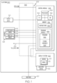
FIG. 1 , in an embodiment, a flight guidance system employing the throttle rate control system 102 (also referred to herein as "system" 102) is generally associated with amobile platform 100. In various embodiments, themobile platform 100 is an aircraft, and is referred to asaircraft 100. Thesystem 102 embodies thecontrol module 104. Although thecontrol module 104 is shown as an independent functional block, onboard theaircraft 100, in some embodiments, thecontrol module 104 is integrated within a preexisting mobile platform management system, avionics system, cockpit display system (CDS), flight controls system (FCS), or aircraft flight management system (FMS). In some embodiments, thecontrol module 104,user input device 122, anddisplay system 120 are configured as a control display unit (CDU). In other embodiments, thecontrol module 104 may exist in an electronic flight bag (EFB) or portable electronic device (PED), such as a tablet, cellular phone, or the like. In embodiments in which the control module is within an EFB or a PED, thedisplay system 120 anduser input device 122 may also be part of the EFB or PED. - At its broadest level, the
control module 104 may receive a potential flight path acceleration (PFPAcmd) target and generate therefrom delta-throttle control commands, referred to as "throttle level angle rate commands" (TLA_ratecmd) In various embodiments, thecontrol module 104 may be operationally coupled to any combination of the following aircraft systems, which are generally on-board systems: a source of a potential flight path angle acceleration (PFPAcmd); a source of real time (RT)aircraft state data 110; a source ofaircraft constraints 112; a source ofaircraft configuration data 114, including sensor information and pre-programmed information (equipment settings and weight); a source of athrottle 116 setting; a source of athrust level 118 setting; adisplay system 120; and, auser input device 122. In various embodiments, a communication system andfabric 126 may reside onboard and serve to communicatively couple various on-board systems and external sources, such as a source of weather data 50, to thecontrol module 104. The functions of these aircraft systems, and their interaction, are described in more detail below. - In various embodiments, the potential flight path acceleration (PFPAcmd) target may be manually provided via a
user input device 122 called an acceleration inceptor, which is a throttle-like unit configured as an acceleration interface. In other embodiments, the potential flight path acceleration (PFPAcmd) target may be provided by a thrust director module (as described in a co-pending application) or other source of acceleration commands, such as a flight management system (FMS), in communication with a navigation database another software program or algorithm, as described in more detail below. - Real time (RT) aircraft state data generally refers to navigation system data and inertial data. In some embodiments, the source of RT
aircraft state data 110 may be a navigation system, and aircraft state data is sometimes referred to as navigation data. As used herein, "real-time" is interchangeable with current, instantaneous, and actual (as opposed to intended). RT aircraft state data may include any of: an instantaneous location (e.g., the latitude, longitude, orientation, attitude), an instantaneous track (i.e., the direction the aircraft is traveling in relative to some reference), a RT flight path angle, a RT vertical speed, a RT ground speed, a RT instantaneous altitude (or height above ground level), and a current phase of flight of theaircraft 100. In various embodiments, the source ofaircraft state data 110 may include each of: an aircraft data system (ADS), a global positioning system (GPS), inertial reference system (IRS), or a radio-based navigation system (e.g., VHF omni-directional radio range (VOR) or long-range aid to navigation (LORAN)), and may include one or more navigational radios or other sensors suitably configured to support operation of the FMS, as will be appreciated in the art. In various embodiments, the RT aircraft state data is made available by way of the communication system andfabric 126, so other components, such as thecontrol module 104 and thedisplay system 120, may further process and/or handle the aircraft state data. - Avionics 124 data generally includes data that is specific to components and systems of
aircraft 100, such as may be provided by sensors and/or equipment specifications. In an embodiment, avionics status data may be organized asconstraints 112,configurations 114,throttle 116, and thrust 118. In an embodiment,constraints 112 may include a pre-programmed starting weight for theaircraft 100. In an embodiment,constraints 112 may control onboard systems to provide comfort during flight. In an embodiment,constraints 112 may include look up tables; in an embodiment,constraints 112 may further include an aircraft/engine-specific pre-programmed information, such as, look up table defining the constraints on the relationship between an engine thrust (T) level for each throttle level angle (TLA) setting/position, from a minimum TLA to a maximum TLA. Persons with skill in the art are aware that an engine-specific T vs. TLA relationship is generally non-linear. For example, with reference toFIG. 3 , it can be observed that at thelowest TLA 302, there is an associated minimum thrust,T idle 304, and the T is fairly flat as TLA increases toTLA 306. FromTLA 306 toTLA 308, there is a steeper and more nearly linear positive relationship between TLA and engine thrust, T. AfterTLA 308, the T flattens again, approaching a maximum (Tmax) as TLA continues to increase to its maximum. A delta TLA in the range betweenTLA 302 andTLA 306 has a small delta T, whereas the same sized delta TLA in the range betweenTLA 306 andTLA 308 will have a substantially larger delta T. As can be appreciated, the T versusTLA graph 300 will vary for different aircraft and engines. -
Configurations 114 may represent current (real-time) sensed component and system information and/or status for each of various on-board avionics systems; specific to this disclosure, RT aircraft configuration data collectively includes a current weight (W), status of aircraft flaps, landing gear position, status of spoilers, status of air brakes, status of flaps, etc. - Although RT throttle and RT thrust may be considered part of
configurations 114, for the examples herein, we separate them out. Throttle 116 settings provides a current (real-time) sensed throttle level angle (TLA) setting.Thrust 118 settings provides a current (real-time) sensed thrust (T) level, generally in a range from idle to maximum. There may be a delay in time between a RT change in a TLA and a RT T response thereto, i.e., the RT T reaching the constraints T for the TLA. Also, as mentioned in connection withFIG. 2 , there's a relationship between T and TLA, but it may not be not linear. - During operation, the components of avionics status data self-report or provide respective real-time (RT) performance data and sensed data for further processing. Therefore, at least the thrust (T) level, weight (W), and throttle level angle (TLA) setting, are continually updated for further processing.
- A source of weather data 50 provides current weather conditions. Some weather conditions, such as wind, effect airspeed, and are utilized by the
control module 104 in the generation of the TLA_ratecmd. - In various embodiments, communication between
aircraft 100 subsystems is managed by a communication system andfabric 126. The communication system andfabric 126 is configured to support instantaneous (i.e., real time or current) communications between onboard systems (i.e., the navigation system, the navigation database, the various avionics systems, the FMS), thecontrol module 104, and one or more external data source(s) 122. As a functional block, the communication system andfabric 126 may represent one or more transmitters, receivers, and the supporting communications hardware and software required for components of thesystem 102 to communicate as described herein. In various embodiments, the communication system andfabric 126 may have additional communications not directly relied upon herein, such as bidirectional pilot-to-ATC (air traffic control) communications via a datalink; support for an automatic dependent surveillance broadcast system (ADS-B); a communication management function (CMF) uplink; a terminal wireless local area network (LAN) unit (TWLU); an instrument landing system (ILS); and, any other suitable radio communication system that supports communications between theaircraft 100 and the various external source(s). In various embodiments, thecontrol module 104 and communication system andfabric 126 also support controller pilot data link communications (CPDLC), such as through an aircraft communication addressing and reporting system (ACARS) router; in various embodiments, this feature may be referred to as a communications management unit (CNW) or communications management function (CMF). In summary, the communication system andfabric 126 may allow theaircraft 100 and thecontrol module 104 to receive information that would otherwise be unavailable to the pilot and/or co-pilot using only the onboard systems. - The
user input device 122 and thecontrol module 104 are cooperatively configured to allow a user (e.g., a pilot, co-pilot, or crew member) to interact withdisplay devices 20 in thedisplay system 120 and/or other elements of thesystem 102, as described in greater detail below. Depending on the embodiment, theuser input device 122 may be realized as a cursor control device (CCD), keypad, touchpad, keyboard, mouse, touch panel (or touchscreen), joystick, knob, line select key, voice controller, gesture controller, or another suitable device adapted to receive input from a user. When theuser input device 122 is configured as a touchpad or touchscreen, it may be integrated with thedisplay system 120. As used herein, theuser input device 122 may be used to modify or upload theprogram product 166, override the program when it's running, etc. In various embodiments, thedisplay system 120 anduser input device 122 are onboard theaircraft 100 and are also operationally coupled to the communication system andfabric 126. - In various embodiments, the
control module 104, alone, or as part of a central management computer (CMS) or a flight management system (FMS), loadsinstructions 160 to thereby be programmed withinstructions 160. The control module executesinstructions 160 and thereby draws upon input data and information to provide real-time flight guidance foraircraft 100. The real time flight guidance may be provided to a user by way of graphics and commands for thedisplay system 120, an audio system, or the like. For example, thecontrol module 104 may compare an instantaneous (current) position and heading of theaircraft 100 with the prescribed or intended flight plan data for theaircraft 100 and generate display commands to renderimages 22 distinguishing these features. Thecontrol module 104 may further associate a respective airport, its geographic location, runways (and their respective orientations and/or directions), instrument procedures (e.g., approach procedures, arrival routes and procedures, takeoff procedures, and the like), airspace restrictions, and/or other information or attributes associated with the respective airport (e.g., widths and/or weight limits of taxi paths, the type of surface of the runways or taxi path, and the like) with the instantaneous position and heading of theaircraft 100 and/or with the weather data 50. - The
control module 104 generates throttle control commands (TLA_ratecmd) to thereby control thethrottle 116 in an avionics system. In various embodiments, thecontrol module 104 is also used in conjunction with theuser interface 122 to allow a user to adjust parameters and display various intermediate determinations. When causing a display of information, thecontrol module 104 generates display commands for thedisplay system 120 to cause thedisplay device 20 to render thereon theimage 22, comprising various graphical user interface elements, tables, icons, alerts, menus, buttons, and pictorial images, as described herein. Thedisplay system 120 is configured to continuously receive and process the display commands from thecontrol module 104. Thedisplay system 120 includes adisplay device 20 for presenting animage 22. In various embodiments described herein, thedisplay system 120 includes a synthetic vision system (SVS), and theimage 22 is an SVS image. In exemplary embodiments, thedisplay device 20 is realized on one or more electronic display devices configured as any combination of: a head up display (HUD), an alphanumeric display, a vertical situation display (VSD) and a lateral navigation display (ND). - The
control module 104 performs the functions of thesystem 102. As used herein, the term "module" refers to any means for facilitating communications and/or interaction between the elements of thesystem 102 and performing additional processes, tasks and/or functions to support operation of thesystem 102, as described herein. In various embodiments, thecontrol module 104 may be any hardware, software, firmware, electronic control component, processing logic, and/or processor device, individually or in any combination. Depending on the embodiment, thecontrol module 104 may be implemented or realized with a general purpose processor (shared, dedicated, or group) controller, microprocessor, or microcontroller, and memory that executes one or more software or firmware programs; a content addressable memory; a digital signal processor; an application specific integrated circuit (ASIC), a field programmable gate array (FPGA); any suitable programmable logic device; combinational logic circuit including discrete gates or transistor logic; discrete hardware components and memory devices; and/or any combination thereof, designed to perform the functions described herein. - Accordingly, in
FIG. 1 , an embodiment of thecontrol module 104 is depicted as an enhanced computer system including aprocessor 150 and amemory 152. Theprocessor 150 may comprise any type of processor or multiple processors, single integrated circuits such as a microprocessor, or any suitable number of integrated circuit devices and/or circuit boards working in cooperation to carry out the described operations, tasks, and functions by manipulating electrical signals representing data bits at memory locations in the system memory, as well as other processing of signals. Thememory 152 may comprise RAM memory, ROM memory, flash memory, registers, a hard disk, or another suitable non-transitory short or long-term storage media capable of storing computer-executable programming instructions or other data for execution. Thememory 152 may be located on and/or co-located on the same computer chip as theprocessor 150. Generally, thememory 152 maintains data bits and may be utilized by theprocessor 150 as storage and/or a scratch pad during operation. Information in thememory 152 may be organized and/or imported from an external data source during an initialization step of a process; it may also be programmed via auser input device 122. In some embodiments, thedatabase 156 is part of thememory 152. In some embodiments, theinstructions 160,program 162, and storedvariables 164 are pre-loaded into thememory 152 or thedatabase 156, and are, therefore, internal to thecontrol module 104. - The
program 162 includes previously described auto-throttle inner loop control algorithm, comprising rules and instructions which, when executed, convert theprocessor 150/memory 152/database 156 configuration into thecontrol module 104 that performs the functions, techniques, and processing tasks attributed to the operation of thesystem 102.Novel program 162 and associated storedvariables 164 may be stored in a functional form on computer readable media, for example, as depicted, inmemory 152. While the depicted exemplary embodiment is described in the context of a fully functioning computer system, those skilled in the art will recognize that the mechanisms of the present disclosure are capable of being distributed as aprogram product 166. As aprogram product 166, one or more types of non-transitory computer-readable signal bearing media may be used to store and distribute theprogram 162, such as a non-transitory computer readable medium bearing theprogram 162 and containing therein additional computer instructions for causing a computer processor (such as the processor 150) to load and execute theprogram 162. Such aprogram product 166 may take a variety of forms, and the present disclosure applies equally regardless of the type of computer-readable signal bearing media used to carry out the distribution. Examples of signal bearing media include: recordable media such as floppy disks, hard drives, memory cards and optical disks, and transmission media such as digital and analog communication links. It will be appreciated that cloud-based storage and/or other techniques may also be utilized in certain embodiments. - In various embodiments, the processor/memory unit of the
control module 104 may be communicatively coupled (via a bus 155) to an input/output (I/O)interface 154, and adatabase 156. The bus 155 serves to transmit programs, data, status and other information or signals between the various components of thecontrol module 104. The bus 155 can be any suitable physical or logical means of connecting computer systems and components. This includes, but is not limited to, direct hard-wired connections, fiber optics, infrared and wireless bus technologies. - The I/
O interface 154 enablesintra control module 104 communication, as well as communications between thecontrol module 104 andother system 102 components, and between thecontrol module 104 and the external data sources via the communication system andfabric 126. The I/O interface 154 may include one or more network interfaces and can be implemented using any suitable method and apparatus. In various embodiments, the I/O interface 154 is configured to support communication from an external system driver and/or another computer system. In one embodiment, the I/O interface 154 is integrated with the communication system andfabric 126 and obtains data from external data source(s) directly. Also, in various embodiments, the I/O interface 154 may support communication with technicians, and/or one or more storage interfaces for direct connection to storage apparatuses, such as thedatabase 156. - As mentioned, Primary Flight Displays (PFDs) promote easy recognition of whether the aircraft is climbing or descending. When an FPA cue position is above the horizon, the aircraft is climbing, and when the FPA cue position is below the horizon, the aircraft is descending. The addition of a Potential Flight Path Angle (PFPA) cue to the PFD, as disclosed in Wyatt, et al,
U.S. Patent Application Publication number 15/700,416 , "AUTOMATIC FLIGHT CONTROL SYSTEMS AND METHODS") has improved a pilot's recognition of the aircraft's current energy state. A PFPA cue above/below the FPA cue indicates that the aircraft is accelerating/decelerating along its current flight path or trajectory. - During operation, the
processor 150 loads and executes one or more programs, algorithms and rules embodied as instructions andapplications 160 contained within thememory 152 and, as such, controls the general operation of thecontrol module 104 as well as thesystem 102. With specific reference to the processes and tasks described herein, theprocessor 150 loads theprogram 162, thereby being uniquely programmed with the novel auto-throttle inner loop control algorithm. Moving now toFIG. 2 , and with continuing reference toFIG. 1 , operation and performance of thesystem 102 are described. - A Potential Flight Path Angle (PFPA) represents the flight path angle that could be maintained at the current airspeed. It can be defined, using small angle approximation, as shown in Eq. 1, below:

- Where FPA is the Flight Path Angle of the aircraft, aFPA is the acceleration/deceleration along the flight path trajectory (also referred to as a flight path vector), and g is the acceleration due to gravity. Since the difference between the PFPA and the aircraft's fight path angle (FPA) represents current acceleration/deceleration, the difference between the PFPA and the aircraft's fight path angle (FPA) is an indicator that provides a simple frame of reference to the pilot to manually control the aircraft's airspeed or move the aircraft to a desired airspeed at a predetermined acceleration/deceleration.
- The increased use of flight path acceleration cues, like the PFPA, to manually control speed on aircraft has made way to guidance cues that provide thrust and speed control commands on this axis of control. Embodiments of an enhanced flight guidance system providing thrust guidance (such as co-submitted provisional application, "SYSTEMS AND METHODS FOR PROVIDING THRUST GUIDANCE RELATED TO FLIGHT PATH ANGLE"), provide a similar role to aircraft having auto-flight functions, by providing an outer loop control function of the overall auto-pilot system. As specifically mentioned in the co-submitted provisional application, when the thrust director cue is used to provide potential flight path acceleration targets (PFPAcmds) as an outer loop control function to an overall auto-
throttle 116 system, it may be desirable to employ an inner loop auto-throttle to manage the control of thethrottle 116 to achieve the flight path acceleration targets PFPAcmds embodied in the thrust director cue. Exemplary embodiments of solution to this technical problem are provided, in which an auto-throttle inner loop control algorithm receives the flight path acceleration targets and generates delta-throttle controls therefrom. As described below, the proposed auto-throttle inner loop control algorithm only requires proper conversion of a target acceleration or target speed at the flight path angle to an equivalent flight path acceleration. - In
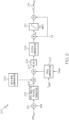
FIG. 2 , the data flow diagram 200 for the proposed inner loop auto-throttle control algorithm is shown. In an embodiment, it receives an input that is acceleration. The input engine power target thrust acceleration command, PFPAcmd, is defined as a function of a flight path acceleration (FPA). As mentioned, the source of the PFPAcmd may be either an outer loop controller that tracks speed or thrust, or a manual interface to the pilot.Operator 212 generates an angle output, which is an error on a potential flight path angle (PFPA) using the target thrust acceleration command, PFPAcmd and the aircraft potential flight path angle (PFPA). The error on the potential flight path angle is an input intoprocess 202. -
Process 202 is essentially a unit converter.Process 202 translates the angle into equivalent acceleration; i.e., PFPA angle to flight path angle acceleration, denotedFPA acceleration 203. Translation atprocess 202 uses Eq. 1, solves for aFPA. The control law algorithm embodied in the data flow diagram 200 converts aFPA into a desired delta-throttle command, denotedthrottle rate TLA_rate cmd 214. - Maintaining a target flight path acceleration by adjusting a current throttle level angle (TLA), as only a function of flight path acceleration error (i.e., at 203), as available solutions often attempt, can result in an inner loop auto-throttle response that is just reactionary, and not capable of anticipating throttle adjustments during maneuvers, configuration changes, engine spool effects or non-linearities of the throttle-to-engine response. The technical solution provided by the inner loop auto-throttle control algorithm advantageously employs several compensation processes to adjust
FPA acceleration 203 in the creation of the desiredTLA_rate cmd 214. - When a turn is initiated or when the aircraft configuration is changed, the drag of the aircraft is affected, thus requiring adjustment to the thrust (T) being applied to maintain the flight path acceleration (FPA). Accordingly, the delta
drag compensation process 204 estimates the amount of delta drag that will occur when either the aircraft configuration changes, and during a maneuver on another axis (i.e. roll, flight path). The deltadrag compensation process 204 uses inputs such as the real time settings for flaps, gear handles, and the Flight Director Commands (when applicable), and responsive thereto, adds an additional acceleration request (first adjustment) to theFPA acceleration 203 to offset/cancel the impact of the configuration changes and/or maneuvers, and minimize the potential of a transient on the desired potential flight path. - The engine spool has the effect of causing undesired overshoots/undershoots in the capture of a potential flight path target due to the delayed response of the thrust (T) acceleration to a throttle level angle (TLA) change, this is also referred to as the spool effect. The
Spool Compensation process 206 monitors the difference between the actual thrust (T actual) and steady state thrust that the engine is promising based on the constraint data (Ttarget) to enable thecontrol module 104 to add an additional acceleration request (second adjustment) to theFPA acceleration 203 to offset/cancel the spool effect. In an embodiment, thespool compensation process 206 may employ a spool threshold, and when a magnitude of the difference between T actual and Ttarget exceeds the spool threshold, the second adjustment is a threshold compensation term. In an embodiment, thespool compensation process 206 may employ a spool function that modifies the magnitude of the difference between T actual and Ttarget, and the second adjustment is a function compensation term, being a function of the magnitude of the difference between T actual and Ttarget, modified by the spool function. -
Process 205 receivesinput 207, which is theFPA acceleration 203 that has been adjusted with the first adjustment and second adjustment. Process 205 referencesaircraft constraints 112 for aircraft performance data and performs acceleration limiting oninput 207. The output fromprocess 205 is then normalized atprocess 208. - Most Engines exhibit a non-linear relationship between Thrust (T) and throttle level angle. As a result, a delta TLA in a first part of a TLA travel window and the same delta TLA in a second part of the TLA travel window can result in two different delta Ts. The Delta Thrust to Delta
TLA compensation process 208 and theTLA limiting process 210 utilize an engine-specific TLA versus T data to linearize this relationship across the entire TLA window. Accordingly, as part of the technical solution provided by thesystem 102,process 208 andprocess 210 allow the inner loop auto-throttle control algorithm to normalize the equivalent acceleration command (after it has been subject to the first adjustment and the second adjustment) based on the throttle location (e.g., the actual servo throttle location). - On commonly available auto-throttles, limiting the throttle positions to the allowed engine ratings is done during an engine-power command to throttle command translation. In the solution provided by the
system 102, the engine-power (i.e., T limits) is either converted directly into equivalent TLA positions or by modulating a difference between engine-power and throttle rating to generate the throttle rate command, TLA_ratecmd. - Notice that the control algorithm embodied in the data flow diagram 200 remains the same for embodiments that receive an input acceleration/deceleration aFPA target (by removing the PFPA to FPA Acceleration translation process 202) and for embodiments that receive an input speed rate target (by modifying the PFPA to FPA
Accel translation process 202 to a Vdot to FPA Acceleration translation), as the core inner loop control law only requires proper conversion of the target to equivalent flight path acceleration. - Referring now to
FIG. 4 and with continued reference toFIGS. 1-3 , a flow chart is provided for amethod 400 for providing throttle rate control, in accordance with various exemplary embodiments. For illustrative purposes, the following description ofmethod 400 may refer to elements mentioned above in connection withFIGS. 1-3 . In practice, portions ofmethod 400 may be performed by different components of the described system. It should be appreciated thatmethod 400 may include any number of additional or alternative tasks, the tasks shown inFIG. 4 need not be performed in the illustrated order, andmethod 400 may be incorporated into a more comprehensive procedure or method having additional functionality not described in detail herein. Moreover, one or more of the tasks shown inFIG. 4 could be omitted from an embodiment of themethod 400 if the intended overall functionality remains intact. - The method starts, and at 402 the
control module 104 is initialized. As mentioned above, initialization may comprise uploading or updating instructions andapplications 160,program 162, storedvariables 164, such as the T vs TLA look-up tables, and the like. Initialization at 402 may also include identifying weather information sources 50 and/or external signals and the communication protocols to use with each of them. - At 402 State data is received, and at 404 avionics data is received. As mentioned, avionics data may include thrust and throttle information, as well as aircraft-specific constraints and sensed configuration information. Data received at 402 and 404 may be used to generate the PFPA input to
operator 212. At 408, an acceleration command, such as PFPACMD may be received. At 410,operator 212 outputs an error on the PFPA that is in angular form, and at 412, themethod 400 converts the error into anFPA acceleration 203. - At 414, the delta
drag compensation process 204 may perform a first adjustment on theFPA acceleration 203 and at 416, theSpool compensation process 206 may perform a second adjustment on theFPA acceleration 203. At 418,process 205 performs a normalization on theinput 207, which is theFPA acceleration 203 that has been adjusted with the first adjustment and second adjustment. At 420, delta T vs delta TLA compensation is performed byprocess 208. At 422, the TLA_rateCMD is generated. - Accordingly, the exemplary embodiments discussed above provide a method for implementing a novel auto-throttle inner loop control algorithm. The novel auto-throttle inner loop control algorithm extends capabilities of vehicle control systems to automatically implement delta-throttle changes which can directly, and without further human manipulation, control an auto-throttle system to achieve acceleration targets, such as PFPAcmds.
- While at least one exemplary embodiment has been presented in the foregoing detailed description of the invention, it should be appreciated that a vast number of variations exist. It should also be appreciated that the exemplary embodiment or exemplary embodiments are only examples, and are not intended to limit the scope, applicability, or configuration of the invention in any way. Rather, the foregoing detailed description will provide those skilled in the art with a convenient road map for implementing an exemplary embodiment of the invention. It being understood that various changes may be made in the function and arrangement of elements described in an exemplary embodiment without departing from the scope of the invention as set forth in the appended claims.
Claims (4)
- A processor-implemented method for providing throttle rate control, comprising:receiving aircraft constraints;receiving engine-specific throttle level angle versus thrust data, the engine-specific throttle level angle versus thrust data comprising data allowing for linearization of the relationship between engine thrust and throttle level angle across all throttle level angles;receiving a thrust acceleration command (PFPAcmd);receiving a throttle level angle (TLA), which is a real time (RT) throttle setting;receiving a RT thrust (T) setting, the thrust setting comprising a current sensed thrust level;generating an error (410) on a potential flight path angle (PFPA) using the thrust acceleration command, the potential flight path angle (PFPA) being defined by:
 where FPA is the flight path angle of the aircraft, aFPA is the acceleration or deceleration along the flight path trajectory and g is acceleration due to gravity;converting (412) the error on the potential flight path angle into an equivalent acceleration;performing (418) a normalization on the equivalent acceleration on the basis of the received engine-specific throttle level angle versus thrust data, using the received throttle level angle and the received RT thrust setting such that the equivalent acceleration is normalized relative to throttle location;performing a delta thrust vs. delta throttle level angle compensation; andgenerating a throttle rate command TLA_ratecmd by converting the equivalent acceleration into the throttle rate command TLA_ratecmd, using the aircraft constraints and the delta thrust vs. delta throttle level angle compensation.
 - The processor-implemented method of claim 1, further comprising:receiving aircraft configuration data; andgenerating the throttle rate command TLA_ratecmd by making a first adjustment to the equivalent acceleration as a function of the aircraft configuration data.
- The processor-implemented method of claim 2, further comprising:employing (416) a spool function that modifies the magnitude of the difference between T actual and Ttarget,; andwherein the second adjustment is a function compensation term.
- A system for providing throttle rate control, comprising:a source of aircraft state data;a source of aircraft constraints;a source of engine-specific throttle level angle versus thrust data, the engine-specific throttle level angle versus thrust data comprising data allowing for linearization of the relationship between engine thrust and throttle level angle across all throttle level angles;a source of a thrust acceleration command (PFPAcmd);a source of a real time (RT) throttle level angle (TLA) that is a throttle setting;a source of a RT thrust (T) setting, the thrust setting comprising a current sensed thrust level;a processor operationally coupled to the source of aircraft constraints, the source of a thrust acceleration command, the source of a RT TLA, and the source of a RT T setting, the processor programmed to perform the method of any preceding claim.
Applications Claiming Priority (2)
| Application Number | Priority Date | Filing Date | Title |
|---|---|---|---|
| US201862782841P | 2018-12-20 | 2018-12-20 | |
| US16/672,105 US11299285B2 (en) | 2018-12-20 | 2019-11-01 | Systems and methods for providing throttle guidance as a function of flight path acceleration |
Publications (2)
| Publication Number | Publication Date |
|---|---|
| EP3671398A1 EP3671398A1 (en) | 2020-06-24 |
| EP3671398B1 true EP3671398B1 (en) | 2023-09-06 |
Family
ID=68965741
Family Applications (1)
| Application Number | Title | Priority Date | Filing Date |
|---|---|---|---|
| EP19217753.3A Active EP3671398B1 (en) | 2018-12-20 | 2019-12-18 | Systems and methods for providing throttle guidance as a function of flight path acceleration |
Country Status (2)
| Country | Link |
|---|---|
| US (1) | US11299285B2 (en) |
| EP (1) | EP3671398B1 (en) |
Families Citing this family (4)
| Publication number | Priority date | Publication date | Assignee | Title |
|---|---|---|---|---|
| US20210141394A1 (en) * | 2019-09-16 | 2021-05-13 | Honeywell International Inc. | Systems and methods for energy managed autoflight guidance using potential flight path angle |
| CN113138577B (en) * | 2021-05-14 | 2022-05-20 | 北京理工大学 | Overload feedback control method for vertical channel of quad-rotor unmanned aerial vehicle |
| CN113759830B (en) * | 2021-09-02 | 2023-04-18 | 浙江大学 | Linear path numerical control machining feed speed control method based on equivalent acceleration |
| US20230205229A1 (en) * | 2021-12-23 | 2023-06-29 | Electra Aero, Inc. | System and method for controlling flight path of a blown lift aircraft |
Family Cites Families (38)
| Publication number | Priority date | Publication date | Assignee | Title |
|---|---|---|---|---|
| US3691356A (en) | 1970-12-10 | 1972-09-12 | Sperry Rand Corp | Speed command and throttle control system for aircraft |
| US4534000A (en) | 1975-08-29 | 1985-08-06 | Bliss John H | Inertial flight director system |
| US4569021A (en) | 1978-08-07 | 1986-02-04 | The Boeing Company | Full flight regime autothrottle control system |
| US4205814A (en) | 1978-08-07 | 1980-06-03 | The Boeing Company | Mach hold control circuit for autothrottle system |
| US4277041A (en) | 1978-09-11 | 1981-07-07 | Lockheed Corporation | Aircraft cruise speed control system |
| US4422147A (en) | 1980-09-08 | 1983-12-20 | The Boeing Company | Wind shear responsive turbulence compensated aircraft throttle control system |
| US4490793A (en) | 1981-12-21 | 1984-12-25 | Sperry Corporation | Cruise speed control for aircraft performance management system |
| US4589616A (en) | 1984-01-24 | 1986-05-20 | Sperry Corporation | Cruise airspeed control of aircraft altitude capture |
| US4811230A (en) * | 1986-08-15 | 1989-03-07 | Boeing Company | Intervention flight management system |
| US5000404A (en) | 1987-08-13 | 1991-03-19 | Grumman Aerospace Corporation | Aircraft precision approach control system |
| US4912642A (en) | 1987-09-03 | 1990-03-27 | The Boeing Company | Coordinated engine autothrottle |
| US5079711A (en) | 1990-02-26 | 1992-01-07 | The Boeing Company | Aircraft high altitude vertical flight path and speed control system |
| EP0482250B1 (en) | 1990-10-25 | 1996-01-17 | The Boeing Company | Automatic airspeed control system for airplane autothrottles |
| US5188316A (en) | 1991-12-30 | 1993-02-23 | Dover Corporation | Aircraft autothrottle system |
| US5349532A (en) | 1992-04-28 | 1994-09-20 | Space Systems/Loral | Spacecraft attitude control and momentum unloading using gimballed and throttled thrusters |
| US5502364A (en) | 1993-07-26 | 1996-03-26 | The Boeing Company | Aircraft automatic throttle forward stop servo system and method |
| US5833177A (en) * | 1995-05-15 | 1998-11-10 | The Boeing Company | Autopilot/flight director overspeed protection system |
| US5746392A (en) * | 1995-05-15 | 1998-05-05 | The Boeing Company | Autopilot/flight director underspeed protection system |
| US6186447B1 (en) * | 1997-11-10 | 2001-02-13 | The Boeing Company | Autothrottle retard rate control system |
| US6507782B1 (en) * | 2001-05-14 | 2003-01-14 | Honeywell International Inc. | Aircraft control system for reaching a waypoint at a required time of arrival |
| US6870490B2 (en) * | 2001-08-23 | 2005-03-22 | Honeywell International Inc. | Display of altitude and path capture trajectories |
| US6963795B2 (en) * | 2002-07-16 | 2005-11-08 | Honeywell Interntaional Inc. | Vehicle position keeping system |
| FR2913780B1 (en) * | 2007-03-13 | 2014-07-18 | Airbus France | METHOD AND DEVICE FOR AIDING THE GUIDANCE OF AN AIRCRAFT |
| US8024080B2 (en) | 2008-06-26 | 2011-09-20 | Safe Flight Instrument Corporation | Automated throttle control system |
| CA2756159C (en) | 2009-03-26 | 2017-05-02 | Ohio University | Trajectory tracking flight controller |
| BR112012017154B1 (en) | 2009-12-21 | 2021-09-28 | The Boeing Company | METHOD OF CONTROLLING THE TILT ATTITUDE OF A MULTIMOTOR AIRCRAFT EXPERIMENTING PUSH AND SYSTEM ASYMMETRY FOR A MULTIMOTOR AIRCRAFT |
| US8311687B2 (en) | 2010-07-30 | 2012-11-13 | Ge Aviation Systems Llc | Method and system for vertical navigation using time-of-arrival control |
| US9086280B2 (en) * | 2011-09-07 | 2015-07-21 | Honeywell International Inc. | Aircraft display systems and methods with flight plan deviation symbology |
| EP2788722A4 (en) * | 2011-12-06 | 2015-05-27 | Airservices Australia | A flight prediction system |
| US9061756B2 (en) * | 2013-04-23 | 2015-06-23 | The Boeing Company | Aircraft performance monitoring system |
| FR3016158B1 (en) | 2014-01-09 | 2017-09-01 | Airbus Operations Sas | DEVICE FOR PROTECTING ENERGY FOR AN AIRCRAFT. |
| US9346552B2 (en) * | 2014-04-11 | 2016-05-24 | Safe Flight Instrument Corporation | Autothrottle retard control |
| US9224302B1 (en) | 2014-05-21 | 2015-12-29 | Rockwell Collins, Inc. | Four dimensional flight management with time control system and related method |
| EP3635501B1 (en) | 2017-06-07 | 2024-05-01 | Turbulence Solutions GmbH | Method and controller for controlling an aircraft by improved direct lift control |
| US10175698B1 (en) * | 2017-09-11 | 2019-01-08 | Honeywell International Inc. | Automatic flight control systems and methods |
| US10793286B1 (en) * | 2018-08-23 | 2020-10-06 | Rockwell Collins, Inc. | Vision based autonomous landing using flight path vector |
| US11029706B2 (en) * | 2018-12-07 | 2021-06-08 | The Boeing Company | Flight control system for determining a fault based on error between a measured and an estimated angle of attack |
| US20210141394A1 (en) * | 2019-09-16 | 2021-05-13 | Honeywell International Inc. | Systems and methods for energy managed autoflight guidance using potential flight path angle |
-
2019
- 2019-11-01 US US16/672,105 patent/US11299285B2/en active Active
- 2019-12-18 EP EP19217753.3A patent/EP3671398B1/en active Active
Also Published As
| Publication number | Publication date |
|---|---|
| US11299285B2 (en) | 2022-04-12 |
| US20200198796A1 (en) | 2020-06-25 |
| EP3671398A1 (en) | 2020-06-24 |
Similar Documents
| Publication | Publication Date | Title |
|---|---|---|
| EP3671398B1 (en) | Systems and methods for providing throttle guidance as a function of flight path acceleration | |
| US11120694B2 (en) | Systems and methods for providing thrust guidance related to flight path angle | |
| US9849999B1 (en) | Avionics interface | |
| US9234982B2 (en) | Aircraft systems and methods for displaying weather information along a flight path | |
| EP2679959B1 (en) | Avionics display system providing enhanced flight-plan management | |
| EP3792724B1 (en) | Systems and methods for energy managed autoflight guidance using potential flight path angle | |
| US8666567B2 (en) | Systems and methods for controlling the speed of an aircraft | |
| CN109491399B (en) | Automatic flight control system and method | |
| US11043131B2 (en) | Systems and methods for generating a recapture path for an aircraft | |
| EP3477260B1 (en) | Aircraft systems and methods for approach stabilization | |
| US10894613B2 (en) | Searchlight auto-land system | |
| US11275388B2 (en) | Systems and methods for an enhanced stable approach monitor | |
| US10676210B2 (en) | Lock-detecting system | |
| EP4012684A1 (en) | Dynamic radar vectoring guidance methods and systems | |
| US11842629B2 (en) | Dynamic radar vectoring guidance methods and systems | |
| US11645924B2 (en) | Variable energy management methods and systems | |
| US11587447B2 (en) | Dynamically modifiable parameters in required time of arrival (RTA) regions of an assigned flight path | |
| EP3992950A1 (en) | Variable energy management methods and systems | |
| US20190161202A1 (en) | Method and system for selecting and displaying an operating protocol for an aerial vehicle |
Legal Events
| Date | Code | Title | Description |
|---|---|---|---|
| PUAI | Public reference made under article 153(3) epc to a published international application that has entered the european phase |
Free format text: ORIGINAL CODE: 0009012 |
|
| STAA | Information on the status of an ep patent application or granted ep patent |
Free format text: STATUS: THE APPLICATION HAS BEEN PUBLISHED |
|
| AK | Designated contracting states |
Kind code of ref document: A1 Designated state(s): AL AT BE BG CH CY CZ DE DK EE ES FI FR GB GR HR HU IE IS IT LI LT LU LV MC MK MT NL NO PL PT RO RS SE SI SK SM TR |
|
| AX | Request for extension of the european patent |
Extension state: BA ME |
|
| STAA | Information on the status of an ep patent application or granted ep patent |
Free format text: STATUS: REQUEST FOR EXAMINATION WAS MADE |
|
| 17P | Request for examination filed |
Effective date: 20201211 |
|
| RBV | Designated contracting states (corrected) |
Designated state(s): AL AT BE BG CH CY CZ DE DK EE ES FI FR GB GR HR HU IE IS IT LI LT LU LV MC MK MT NL NO PL PT RO RS SE SI SK SM TR |
|
| STAA | Information on the status of an ep patent application or granted ep patent |
Free format text: STATUS: EXAMINATION IS IN PROGRESS |
|
| 17Q | First examination report despatched |
Effective date: 20210408 |
|
| RAP3 | Party data changed (applicant data changed or rights of an application transferred) |
Owner name: HONEYWELL INTERNATIONAL INC. |
|
| GRAP | Despatch of communication of intention to grant a patent |
Free format text: ORIGINAL CODE: EPIDOSNIGR1 |
|
| STAA | Information on the status of an ep patent application or granted ep patent |
Free format text: STATUS: GRANT OF PATENT IS INTENDED |
|
| INTG | Intention to grant announced |
Effective date: 20230327 |
|
| P01 | Opt-out of the competence of the unified patent court (upc) registered |
Effective date: 20230421 |
|
| GRAS | Grant fee paid |
Free format text: ORIGINAL CODE: EPIDOSNIGR3 |
|
| GRAA | (expected) grant |
Free format text: ORIGINAL CODE: 0009210 |
|
| STAA | Information on the status of an ep patent application or granted ep patent |
Free format text: STATUS: THE PATENT HAS BEEN GRANTED |
|
| AK | Designated contracting states |
Kind code of ref document: B1 Designated state(s): AL AT BE BG CH CY CZ DE DK EE ES FI FR GB GR HR HU IE IS IT LI LT LU LV MC MK MT NL NO PL PT RO RS SE SI SK SM TR |
|
| REG | Reference to a national code |
Ref country code: GB Ref legal event code: FG4D |
|
| REG | Reference to a national code |
Ref country code: CH Ref legal event code: EP |
|
| REG | Reference to a national code |
Ref country code: IE Ref legal event code: FG4D |
|
| REG | Reference to a national code |
Ref country code: DE Ref legal event code: R096 Ref document number: 602019036684 Country of ref document: DE |
|
| REG | Reference to a national code |
Ref country code: DE Ref legal event code: R079 Ref document number: 602019036684 Country of ref document: DE Free format text: PREVIOUS MAIN CLASS: G05D0001060000 Ipc: G05D0001485000 |
|
| REG | Reference to a national code |
Ref country code: LT Ref legal event code: MG9D |
|
| REG | Reference to a national code |
Ref country code: NL Ref legal event code: MP Effective date: 20230906 |
|
| PG25 | Lapsed in a contracting state [announced via postgrant information from national office to epo] |
Ref country code: GR Free format text: LAPSE BECAUSE OF FAILURE TO SUBMIT A TRANSLATION OF THE DESCRIPTION OR TO PAY THE FEE WITHIN THE PRESCRIBED TIME-LIMIT Effective date: 20231207 |
|
| PG25 | Lapsed in a contracting state [announced via postgrant information from national office to epo] |
Ref country code: SE Free format text: LAPSE BECAUSE OF FAILURE TO SUBMIT A TRANSLATION OF THE DESCRIPTION OR TO PAY THE FEE WITHIN THE PRESCRIBED TIME-LIMIT Effective date: 20230906 Ref country code: RS Free format text: LAPSE BECAUSE OF FAILURE TO SUBMIT A TRANSLATION OF THE DESCRIPTION OR TO PAY THE FEE WITHIN THE PRESCRIBED TIME-LIMIT Effective date: 20230906 Ref country code: NO Free format text: LAPSE BECAUSE OF FAILURE TO SUBMIT A TRANSLATION OF THE DESCRIPTION OR TO PAY THE FEE WITHIN THE PRESCRIBED TIME-LIMIT Effective date: 20231206 Ref country code: LV Free format text: LAPSE BECAUSE OF FAILURE TO SUBMIT A TRANSLATION OF THE DESCRIPTION OR TO PAY THE FEE WITHIN THE PRESCRIBED TIME-LIMIT Effective date: 20230906 Ref country code: LT Free format text: LAPSE BECAUSE OF FAILURE TO SUBMIT A TRANSLATION OF THE DESCRIPTION OR TO PAY THE FEE WITHIN THE PRESCRIBED TIME-LIMIT Effective date: 20230906 Ref country code: HR Free format text: LAPSE BECAUSE OF FAILURE TO SUBMIT A TRANSLATION OF THE DESCRIPTION OR TO PAY THE FEE WITHIN THE PRESCRIBED TIME-LIMIT Effective date: 20230906 Ref country code: GR Free format text: LAPSE BECAUSE OF FAILURE TO SUBMIT A TRANSLATION OF THE DESCRIPTION OR TO PAY THE FEE WITHIN THE PRESCRIBED TIME-LIMIT Effective date: 20231207 Ref country code: FI Free format text: LAPSE BECAUSE OF FAILURE TO SUBMIT A TRANSLATION OF THE DESCRIPTION OR TO PAY THE FEE WITHIN THE PRESCRIBED TIME-LIMIT Effective date: 20230906 |
|
| PGFP | Annual fee paid to national office [announced via postgrant information from national office to epo] |
Ref country code: FR Payment date: 20231226 Year of fee payment: 5 |
|
| REG | Reference to a national code |
Ref country code: AT Ref legal event code: MK05 Ref document number: 1609357 Country of ref document: AT Kind code of ref document: T Effective date: 20230906 |
|
| PG25 | Lapsed in a contracting state [announced via postgrant information from national office to epo] |
Ref country code: NL Free format text: LAPSE BECAUSE OF FAILURE TO SUBMIT A TRANSLATION OF THE DESCRIPTION OR TO PAY THE FEE WITHIN THE PRESCRIBED TIME-LIMIT Effective date: 20230906 |
|
| PG25 | Lapsed in a contracting state [announced via postgrant information from national office to epo] |
Ref country code: IS Free format text: LAPSE BECAUSE OF FAILURE TO SUBMIT A TRANSLATION OF THE DESCRIPTION OR TO PAY THE FEE WITHIN THE PRESCRIBED TIME-LIMIT Effective date: 20240106 |
|
| PG25 | Lapsed in a contracting state [announced via postgrant information from national office to epo] |
Ref country code: AT Free format text: LAPSE BECAUSE OF FAILURE TO SUBMIT A TRANSLATION OF THE DESCRIPTION OR TO PAY THE FEE WITHIN THE PRESCRIBED TIME-LIMIT Effective date: 20230906 |
|
| PG25 | Lapsed in a contracting state [announced via postgrant information from national office to epo] |
Ref country code: ES Free format text: LAPSE BECAUSE OF FAILURE TO SUBMIT A TRANSLATION OF THE DESCRIPTION OR TO PAY THE FEE WITHIN THE PRESCRIBED TIME-LIMIT Effective date: 20230906 |
|
| PG25 | Lapsed in a contracting state [announced via postgrant information from national office to epo] |
Ref country code: SM Free format text: LAPSE BECAUSE OF FAILURE TO SUBMIT A TRANSLATION OF THE DESCRIPTION OR TO PAY THE FEE WITHIN THE PRESCRIBED TIME-LIMIT Effective date: 20230906 Ref country code: RO Free format text: LAPSE BECAUSE OF FAILURE TO SUBMIT A TRANSLATION OF THE DESCRIPTION OR TO PAY THE FEE WITHIN THE PRESCRIBED TIME-LIMIT Effective date: 20230906 Ref country code: IS Free format text: LAPSE BECAUSE OF FAILURE TO SUBMIT A TRANSLATION OF THE DESCRIPTION OR TO PAY THE FEE WITHIN THE PRESCRIBED TIME-LIMIT Effective date: 20240106 Ref country code: ES Free format text: LAPSE BECAUSE OF FAILURE TO SUBMIT A TRANSLATION OF THE DESCRIPTION OR TO PAY THE FEE WITHIN THE PRESCRIBED TIME-LIMIT Effective date: 20230906 Ref country code: EE Free format text: LAPSE BECAUSE OF FAILURE TO SUBMIT A TRANSLATION OF THE DESCRIPTION OR TO PAY THE FEE WITHIN THE PRESCRIBED TIME-LIMIT Effective date: 20230906 Ref country code: CZ Free format text: LAPSE BECAUSE OF FAILURE TO SUBMIT A TRANSLATION OF THE DESCRIPTION OR TO PAY THE FEE WITHIN THE PRESCRIBED TIME-LIMIT Effective date: 20230906 Ref country code: AT Free format text: LAPSE BECAUSE OF FAILURE TO SUBMIT A TRANSLATION OF THE DESCRIPTION OR TO PAY THE FEE WITHIN THE PRESCRIBED TIME-LIMIT Effective date: 20230906 Ref country code: SK Free format text: LAPSE BECAUSE OF FAILURE TO SUBMIT A TRANSLATION OF THE DESCRIPTION OR TO PAY THE FEE WITHIN THE PRESCRIBED TIME-LIMIT Effective date: 20230906 Ref country code: PT Free format text: LAPSE BECAUSE OF FAILURE TO SUBMIT A TRANSLATION OF THE DESCRIPTION OR TO PAY THE FEE WITHIN THE PRESCRIBED TIME-LIMIT Effective date: 20240108 |
|
| PGFP | Annual fee paid to national office [announced via postgrant information from national office to epo] |
Ref country code: DE Payment date: 20231227 Year of fee payment: 5 |