EP3667473B1 - System and method for multi-mode command input - Google Patents
System and method for multi-mode command input Download PDFInfo
- Publication number
- EP3667473B1 EP3667473B1 EP20154656.1A EP20154656A EP3667473B1 EP 3667473 B1 EP3667473 B1 EP 3667473B1 EP 20154656 A EP20154656 A EP 20154656A EP 3667473 B1 EP3667473 B1 EP 3667473B1
- Authority
- EP
- European Patent Office
- Prior art keywords
- controlling device
- sensitive surface
- touch sensitive
- recited
- touch
- Prior art date
- Legal status (The legal status is an assumption and is not a legal conclusion. Google has not performed a legal analysis and makes no representation as to the accuracy of the status listed.)
- Active
Links
- 238000000034 method Methods 0.000 title claims description 13
- 230000006870 function Effects 0.000 claims description 19
- 230000015654 memory Effects 0.000 claims description 18
- 230000005540 biological transmission Effects 0.000 claims description 9
- 229920002379 silicone rubber Polymers 0.000 claims description 7
- 230000033001 locomotion Effects 0.000 claims description 6
- 230000004913 activation Effects 0.000 claims description 5
- 230000004044 response Effects 0.000 claims description 5
- 239000011159 matrix material Substances 0.000 description 8
- NIXOWILDQLNWCW-UHFFFAOYSA-N acrylic acid group Chemical group C(C=C)(=O)O NIXOWILDQLNWCW-UHFFFAOYSA-N 0.000 description 7
- 230000003993 interaction Effects 0.000 description 5
- 230000007246 mechanism Effects 0.000 description 5
- 230000009471 action Effects 0.000 description 4
- 238000001514 detection method Methods 0.000 description 4
- 230000000694 effects Effects 0.000 description 4
- 230000008859 change Effects 0.000 description 3
- 238000004519 manufacturing process Methods 0.000 description 3
- XUIMIQQOPSSXEZ-UHFFFAOYSA-N Silicon Chemical compound [Si] XUIMIQQOPSSXEZ-UHFFFAOYSA-N 0.000 description 2
- 230000006835 compression Effects 0.000 description 2
- 238000007906 compression Methods 0.000 description 2
- 238000010586 diagram Methods 0.000 description 2
- 238000005286 illumination Methods 0.000 description 2
- 229910052710 silicon Inorganic materials 0.000 description 2
- 239000010703 silicon Substances 0.000 description 2
- 238000010276 construction Methods 0.000 description 1
- 239000013078 crystal Substances 0.000 description 1
- 230000001419 dependent effect Effects 0.000 description 1
- 230000000994 depressogenic effect Effects 0.000 description 1
- 239000004973 liquid crystal related substance Substances 0.000 description 1
- 239000000463 material Substances 0.000 description 1
- 230000004048 modification Effects 0.000 description 1
- 238000012986 modification Methods 0.000 description 1
- 230000003287 optical effect Effects 0.000 description 1
- 230000008054 signal transmission Effects 0.000 description 1
- 230000000007 visual effect Effects 0.000 description 1
Images

Classifications
-
- G—PHYSICS
- G06—COMPUTING; CALCULATING OR COUNTING
- G06F—ELECTRIC DIGITAL DATA PROCESSING
- G06F3/00—Input arrangements for transferring data to be processed into a form capable of being handled by the computer; Output arrangements for transferring data from processing unit to output unit, e.g. interface arrangements
- G06F3/01—Input arrangements or combined input and output arrangements for interaction between user and computer
- G06F3/02—Input arrangements using manually operated switches, e.g. using keyboards or dials
- G06F3/0202—Constructional details or processes of manufacture of the input device
- G06F3/0219—Special purpose keyboards
-
- G—PHYSICS
- G06—COMPUTING; CALCULATING OR COUNTING
- G06F—ELECTRIC DIGITAL DATA PROCESSING
- G06F3/00—Input arrangements for transferring data to be processed into a form capable of being handled by the computer; Output arrangements for transferring data from processing unit to output unit, e.g. interface arrangements
- G06F3/01—Input arrangements or combined input and output arrangements for interaction between user and computer
- G06F3/03—Arrangements for converting the position or the displacement of a member into a coded form
- G06F3/033—Pointing devices displaced or positioned by the user, e.g. mice, trackballs, pens or joysticks; Accessories therefor
- G06F3/0354—Pointing devices displaced or positioned by the user, e.g. mice, trackballs, pens or joysticks; Accessories therefor with detection of 2D relative movements between the device, or an operating part thereof, and a plane or surface, e.g. 2D mice, trackballs, pens or pucks
- G06F3/03547—Touch pads, in which fingers can move on a surface
-
- G—PHYSICS
- G06—COMPUTING; CALCULATING OR COUNTING
- G06F—ELECTRIC DIGITAL DATA PROCESSING
- G06F3/00—Input arrangements for transferring data to be processed into a form capable of being handled by the computer; Output arrangements for transferring data from processing unit to output unit, e.g. interface arrangements
- G06F3/01—Input arrangements or combined input and output arrangements for interaction between user and computer
- G06F3/03—Arrangements for converting the position or the displacement of a member into a coded form
- G06F3/041—Digitisers, e.g. for touch screens or touch pads, characterised by the transducing means
- G06F3/0414—Digitisers, e.g. for touch screens or touch pads, characterised by the transducing means using force sensing means to determine a position
-
- H—ELECTRICITY
- H01—ELECTRIC ELEMENTS
- H01H—ELECTRIC SWITCHES; RELAYS; SELECTORS; EMERGENCY PROTECTIVE DEVICES
- H01H25/00—Switches with compound movement of handle or other operating part
- H01H25/04—Operating part movable angularly in more than one plane, e.g. joystick
- H01H25/041—Operating part movable angularly in more than one plane, e.g. joystick having a generally flat operating member depressible at different locations to operate different controls
-
- H—ELECTRICITY
- H01—ELECTRIC ELEMENTS
- H01H—ELECTRIC SWITCHES; RELAYS; SELECTORS; EMERGENCY PROTECTIVE DEVICES
- H01H9/00—Details of switching devices, not covered by groups H01H1/00 - H01H7/00
- H01H9/02—Bases, casings, or covers
- H01H9/0214—Hand-held casings
- H01H9/0235—Hand-held casings specially adapted for remote control, e.g. of audio or video apparatus
-
- G—PHYSICS
- G06—COMPUTING; CALCULATING OR COUNTING
- G06F—ELECTRIC DIGITAL DATA PROCESSING
- G06F2203/00—Indexing scheme relating to G06F3/00 - G06F3/048
- G06F2203/041—Indexing scheme relating to G06F3/041 - G06F3/045
- G06F2203/04106—Multi-sensing digitiser, i.e. digitiser using at least two different sensing technologies simultaneously or alternatively, e.g. for detecting pen and finger, for saving power or for improving position detection
-
- G—PHYSICS
- G06—COMPUTING; CALCULATING OR COUNTING
- G06F—ELECTRIC DIGITAL DATA PROCESSING
- G06F3/00—Input arrangements for transferring data to be processed into a form capable of being handled by the computer; Output arrangements for transferring data from processing unit to output unit, e.g. interface arrangements
- G06F3/01—Input arrangements or combined input and output arrangements for interaction between user and computer
- G06F3/03—Arrangements for converting the position or the displacement of a member into a coded form
- G06F3/041—Digitisers, e.g. for touch screens or touch pads, characterised by the transducing means
- G06F3/044—Digitisers, e.g. for touch screens or touch pads, characterised by the transducing means by capacitive means
- G06F3/0447—Position sensing using the local deformation of sensor cells
Definitions
- the operating program of controlling device 100 may next determine if the actuated key is one of the group 310 through 313 associated with touch sensor assembly 302, 304. If not, the key input may represent a conventional button, for example "volume up" 406, and is processed at step 612. Since such conventional key decoding and command output are well known in the art, for the sake of brevity this aspect of controlling device 100 and associated operating program will not be discussed further herein.
Landscapes
- Engineering & Computer Science (AREA)
- General Engineering & Computer Science (AREA)
- Theoretical Computer Science (AREA)
- Human Computer Interaction (AREA)
- Physics & Mathematics (AREA)
- General Physics & Mathematics (AREA)
- Multimedia (AREA)
- Position Input By Displaying (AREA)
- Input From Keyboards Or The Like (AREA)
Description
- Controlling devices for use in issuing commands to entertainment and other appliances, for example remote controls, and the features and functionality provided by such controlling devices are well known in the art. Traditionally, user input means on such controlling devices has comprised a series of buttons each of which may result in the transmission of a specific command when activated.
US 2005/052425 discloses an input device comprising a movable touchpad which can detect an object in close proximity and in response generate control signals for performing actions in a device coupled to the input device. The touchpad is also configured to actuate switches located underneath the touchpad for generating a signal when the touchpad is moved to a depressed position.US 2007/152983 discloses a device having an input pad for providing signals when touched or pressed. The input pad is divided into several input areas that change in accordance with an operating mode of the device. - Increasingly in today's environment, such controlling devices must be used to interact with displayed menu systems, browse web pages, manipulate pointers, and perform other similar activities which may require directional control input, e.g., to scroll displayed information on a screen, to move a pointer, to control a game activity or avatar, to zoom in or out, to control functions such as fast forward or slow motion, or the like (such activities collectively referred to hereinafter as "navigation"). Although certain navigation functions may be performed using conventional controlling device input mechanisms, such as a group of up, down, left, and right arrow keys, in many instances the user experience may be improved by the provision of an input mechanism which is better suited to this type of activity. Additionally, multi-functional use of this input mechanism may further improve user experience by reducing the number of keys or buttons on a controlling device.
- The invention is defined by the independent claims. Further aspects of the invention are outlined in the dependent claims. The following generally describes a system and method for providing improved user input functionality on a controlling device. To this end, in addition to a conventional key matrix for receiving button inputs as is well known in the art, a controlling device is provided with input means such as for example a resistive or capacitive touch sensor, etc., whereby motion and/or pressure by a user's finger are translated into navigation commands to be transmitted to a target controlled device. These commands are applied at the target device to control operations such as scrolling a menu, movement of a cursor on the screen, motion of a game object, etc., as appropriate for a particular application. Furthermore, in addition to, or when not required for, the performance of navigation functions, the touch sensitive input means may be adapted to provide for conventional keypress input operations, such as for example without limitation a numeric keypad in an illustrative embodiment.
- A better understanding of the objects, advantages, features, properties and relationships of the invention will be obtained from the following detailed description and accompanying drawings which set forth illustrative embodiments and which are indicative of the various ways in which the principles of the invention may be employed.
- For a better understanding of the various aspects of the invention, reference may be had to preferred embodiments shown in the attached drawings in which:
-
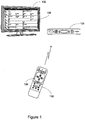
Figure 1 illustrates an exemplary system in which an exemplary controlling device according to the instant invention may be used; -
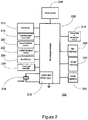
Figure 2 illustrates a block diagram of exemplary components of the exemplary controlling device ofFigure 1 ; -
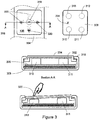
Figure 3 illustrates the structure and operation of an exemplary touch sensitive input area of the exemplary controlling device ofFigure 1 ; -
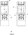
Figure 4 illustrates multiple modes of operation of the exemplary controlling device ofFigure 1 ; -
Figure 5 illustrates exemplary interpretations of user input interactions with a touch sensitive area of the exemplary controlling device ofFigure 4 ; -
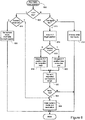
Figure 6 illustrates in flow chart form an exemplary method for performing the interpretations illustrated inFigure 5 ; and -
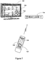
Figure 7 illustrates an alternate embodiment of a controlling device and system in which the teachings of the instant invention may be used. - Turning now to
Figure 1 , there is illustrated an exemplary system in which a controllingdevice 100 is configured to control various controllable appliances, such as for example atelevision 102 and a set top box ("STB") 104. As is known in the art, the controllingdevice 100 may be capable of transmitting commands to the appliances, using any convenient IR, RF, Point-to-Point, or networked protocol, to cause the appliances to perform operational functions. While illustrated in the context of atelevision 102 and STB 104, it is to be understood that controllable appliances may include, but need not be limited to, televisions, VCRs, DVRs, DVD players, cable or satellite converter set-top boxes ("STBs"), amplifiers, CD players, game consoles, home lighting, drapery, fans, HVAC systems, thermostats, personal computers, etc. In a particular illustrative embodiment, in addition to conventional control functionality as is well know in the art, controllingdevice 100 may further include aninput area 106 for generation of navigation commands for transmission from the controllingdevice 100 to one or more appliances in response to user interaction with that area, used for example to scroll a programguide menu display 108 onTV 102 by issuing a series of commands to settop box 104. Additionally, in the exemplary embodiment,input area 106 may be further adapted to offer keypad-like functionality during certain modes of operation, all as will be described in further detail hereafter. - With reference to
Figure 2 , for use in commanding the functional operations of one or more appliances, the controllingdevice 100 may include, as needed for a particular application, aprocessor 200 coupled to aROM memory 204; aRAM memory 202; a key matrix 216 (e.g., hard keys, soft keys such as a touch sensitive surface overlaid on a liquid crystal (LCD), and/or an electroluminescent (EL) display); a scrolling and/or navigation function input means 218 such as a capacitive or resistive touch sensor; transmission circuit(s) and/or transceiver circuit(s) 210 (e.g., IR and/or RF); a non-volatile read/writememory 206; ameans 220 to provide visual feedback to the user (e.g., one or more LEDs, display, and/or the like); ameans 222 to provide audible feedback to a user (e.g., a speaker, piezoelectric buzzer, etc.); apower source 208; an input/output port 224 such as a serial interface, USB port, modem, Zigbee, WiFi, or Bluetooth transceiver, etc.; one ormore means 226 for backlighting areas oftouchpad 218 and/orkey matrix 216; and clock andtimer logic 212 with associated crystal orresonator 214. - As will be understood by those skilled in the art, some or all of the
memories processor 200 to control the operation of theremote control 100, as well as data which serves to define to the operational software the necessary control protocols and command values for use in transmitting command signals to controllable appliances (collectively, the command data). In this manner, theprocessor 200 may be programmed to control the various electronic components within theremote control 100, e.g., to monitor thekey matrix 216, to cause the transmission of signals, etc. The non-volatile read/writememory 206, for example an EEPROM, battery-backed up RAM, FLASH, Smart Card, memory stick, or the like, may additionally be provided to store setup data and parameters as necessary. While thememory 204 is illustrated and described as a ROM memory,memory 204 can also be comprised of any type of readable media, such as ROM, FLASH, EEPROM, or the like. Preferably, thememories memories memories Fig. 2 only for the sake of clarity. - To cause the controlling
device 100 to perform an action, the controllingdevice 100 may be adapted to be responsive to events, such as a sensed user interaction with thekey matrix 216,touchpad 218, etc. In response to an event, appropriate instructions within the program memory (hereafter the "operating program") may be executed. For example, when a function key is actuated on the controllingdevice 100, the controllingdevice 100 may retrieve from the command data stored inmemory device 100 may include displaying information/data, favorite channel setup, macro key setup, function key relocation, etc. Examples of local operations can be found inU.S. Patent Nos. 5,481,256 ,5,959,751 , and6,014,092 . - In some embodiments, controlling
device 100 may be the universal type, that is provisioned with a library comprising a multiplicity of command codes and protocols suitable for controlling various appliances. In such cases, for selecting sets of command data to be associated with the specific appliances to be controlled (hereafter referred to as a setup procedure), data may be entered into the controllingdevice 100 that serves to identify each intended target appliance by its make, and/or model, and/or type. The data may typically be entered via activation of those keys that are also used to cause the transmission of commands to an appliance, preferably the keys that are labeled with numerals. Such data allows the controllingdevice 100 to identify the appropriate command data set within the library of command data that is to be used to transmit recognizable commands in formats appropriate for such identified appliances. The library of command data may represent a plurality of controllable appliances of different types and manufacture, a plurality of controllable appliances of the same type but different manufacture, a plurality of appliances of the same manufacture but different type or model, etc., or any combination thereof as appropriate for a given embodiment. In conventional practice as is well known in the art, such data used to identify an appropriate command data set may take the form of a numeric setup code (obtained, for example, from a printed list of manufacturer names and/or models with corresponding code numbers, from a support Web site, etc.). Alternative setup procedures known in the art include scanning bar codes, sequentially transmitting a predetermined command in different formats until a target appliance response is detected, interaction with a Web site culminating in downloading of command data and/or setup codes to the controlling device, etc. Since such methods for setting up a controlling device to command the operation of specific home appliances are well-known, these will not be described in greater detail herein. - In keeping with the teachings of this invention, controlling
device 100 may include input means for accepting user touch input to be translated into navigation commands. In an exemplary embodiment, input means 218 may take the form of a multiple-electrode capacitive touch sensor. In this form, input means 218 may accept finger sliding gestures on either axis for translation into navigation step commands in an X or Y direction, as well as finger pressure at, for example, the cardinal points and center area for translation into discrete commands, for example equivalent to a conventional keypad's four arrow keys and a select key, all as will be described in further detail hereafter. - Turning to
Figure 3 , the construction of an exemplary navigation input means 218, which may comprisearea 106 of exemplary controllingdevice 100, will now be discussed in detail. Such an input means may comprise the before-mentioned multiple-electrodecapacitive touch sensor 302 and an associatedacrylic keycap 304, positioned upon a group of conventional siliconrubber keypad buttons Silicon rubber keypad 306 andbuttons 310 through 313, which may comprise a portion ofkey matrix 216 as well known in the art, may be supported by printedcircuit board 308 and may serve to hold touch input assembly 302,304 elevated and flush with an associated opening formed in theupper casing 316 of controllingdevice 100. In an exemplary embodiment the surface ofacrylic keycap 304 coveringtouch sensor 302 may include indicia which provide cues to the functionality ofinput means 106, which indicia may be embossed or engraved 320 or printed 318 upon the keycap surface. In certain embodiments additional indicia may also be present onacrylic keycap 304, which additional indicia may be illuminated or otherwise brought into prominence during certain modes of operation, as will be described in further detail hereafter. - In a first input mode, a user may slide a finger across the surface of the touch surface, e.g.,
keycap 304, to cause navigation command output. Such navigation step commands resulting from finger sliding gestures may be reported to a target appliance using any convenient transmission protocol, IR or RF, as known in the art. In general, such reports may include information representative of both direction and speed of the input gesture. Since exemplary gesture interpretation and reporting techniques are presented in the above referenced '761 application, for the sake of brevity these will not be repeated herein. - In a second input mode, which may be used in conjunction with or separately from finger slide input, a user may press downwards 322 anywhere upon the touch surface, e.g.,
acrylic keycap 304. As illustrated, this will result in compression of one or more of the underlyingsilicon rubber buttons 310 through 313, for example button 310' as shown inFig. 3 . As in a conventional keypad, compression of such a button may cause a conductive contact area on the underside of said button to complete an electrical circuit provided for that purpose on printedcircuit board 308, i.e., cause a key press event to be detected by the operating program of controllingdevice 100. In this instance however, the actuation of any one or more ofsilicon rubber buttons 310 through 313 may be interpreted by the operating program of controllingdevice 100 simply as a general signal that the touchpad input area 106 has received a finger press. The actual significance of the event and the command to be issued may then be determined by the operating program of controllingdevice 100 based on the position of the user's finger as reported bytouch sensor 302 at the time the electrical circuit was completed. - By way of further example, if conventional keypress decoding based only on the status of
silicon rubber buttons 310 through 313 were to be employed in this example and user finger pressure was applied atlocation 324, it will be appreciated that the circuits associated with either or both ofbuttons - Certain embodiments of controlling
device 100 may support multiple modes of operation oftouch input area 106. By way of example, with reference toFigure 4 , in an exemplary embodiment the operation oftouch input area 106 of controllingdevice 100 may be user switchable between navigation mode and digit entry mode, for example via a "numeric"toggle button 402, labeled "1-2-3" in the illustrative example. When in the navigation mode, user finger swipes and presses ontouch input area 106 may be interpreted by the operating program of controllingdevice 100 as requests to issue navigation commands as described previously. However, when toggled into digit entry mode by activation ofbutton 402, interpretation of touch area input by the operating program of controllingdevice 100 may change to a represent a twelve-key numeric input pad, with only finger press input recognized. In some embodiments the appearance oftouch input pad 106, in particular that ofacrylic keycap 304, may be altered to signal this mode of operation to a user, as illustrated at 404. Such a change in appearance may be effected, for example, by illumination via backlight of digit indicia laser etched into the surface ofacrylic keycap 304. Illumination may be achieved by one or more LEDs directed towards the edge ofkeycap 304, i.e., using the acrylic material as a light pipe; by conventional backlighting using one or more LEDs mounted on the surface ofcapacitive touch sensor 302; or any other means as appropriate for a particular embodiment. Without limitation, an example of such an illuminable interface is described in commonly assigned, published application no.2006/0283697 - Turning now to
Figure 5 , whenexemplary controlling device 100 is functioning in the normal (i.e., navigation) mode, upon actuation of one or more of thekeypad keys 310 through 313 associated withnavigation pad 106 the operating program of controllingdevice 100 may retrieve the current finger position coordinates "X" 502 and "Y" 504 and translate these values into a command request based upon which one of fivezones 506 the X,Y coordinates are determined to fall within. By way of example, a finger press at theindicated location 512 may be interpreted as occurring withinzone 508 which corresponds in this example to the "left arrow"navigation indicia 514, and the corresponding navigation command issued to the target appliance. In contrast, in an illustrative embodiment, whenexemplary controlling device 100 is functioning in a digit entry mode as a result of actuation of "1-2-3"button 402 the retrieved X,Y coordinates may be interpreted by the operating program of controllingdevice 100 according to a twelvezone schema 520, each zone now corresponding to one of the digits "0" through "9" together with an "Enter" and a "Separator" functions. By way of further example, when functioning in this mode the operating program of controllingdevice 100 may interpret a finger press at location 512' to correspond to the numeric digit "4", and the corresponding numeric digit command issued to the target appliance. - By way of more detailed example, the flowchart of
Figure 6 in conjunction with Tables 1 and 2 present an exemplary method for processing and interpreting user interactions which may be implemented by the operating program of controllingdevice 100 . Turning toFigure 6 , upon detection ofkey matrix input 600 by the operating program of controllingdevice 100, it may be first determined atstep 602 if the actuated key is the "1-2-3" digitentry toggle button 402. If so, atstep 604 it may be next determined if controlling device is already functioning in the numeric entry mode. If not, atstep 606 numeric mode operation status is set to "true" andnumeric indicia 404 illuminated as described earlier. If however, the device is already functioning in the numeric entry mode, then actuation ofbutton 402 may be interpreted a request to exit this mode and return to the navigation mode of operation, which is performed atstep 608. - If the actuated key is not the "1-2-3" button, at
step 610 the operating program of controllingdevice 100 may next determine if the actuated key is one of thegroup 310 through 313 associated withtouch sensor assembly step 612. Since such conventional key decoding and command output are well known in the art, for the sake of brevity this aspect of controllingdevice 100 and associated operating program will not be discussed further herein. - If however, the operating program of controlling
device 100 determines that the actuated key is one or more of thegroup 310 through 313, atstep 614 the "X" and "Y" coordinates of the user's actuating finger position may be ascertained fromtouch sensor 302. Next, in order to establish the interpretation to be applied to these values, atstep 616 the operating program of controllingdevice 100 may determine if touch pad input is currently to be interpreted as digit entry or as navigation entry. If navigation entry is the current operational mode, then atstep 618 the reported X,Y coordinates may be interpreted according to a fivezone model 506 illustrated inFigure 5 . By way of example, without limitation, if the X and Y coordinates are each reported as a linear value in the range 0 to 15 with origin 0,0 at the bottom left corner oftouchpad 302, then an exemplary algorithm as presented in Table 1 below may be applied to resolve the reported coordinate data into one of the five zones and thereby determine the requested appliance navigation command function.
- For example, with reference to the bottom row of Table 1, i.e., when reported Y coordinate is in the range 0 through 4:
- If X is in the range 0 through 4, then
- If Y is greater than X, command equals "left arrow" else
- If Y is less than X, command equals "down arrow" else
- If X is in the range 5 through 10, then command equals "down arrow" else
- If X is in the range 11 through 15, then
- If Y is greater than (X-11), command equals "right arrow" else
- If Y is less than (X-11), command equals "down arrow".
- As will be evident from an examination of Table 1, similar algorithms may be symmetrically applied to the other possible ranges of X and Y to resolve these values as locations within the five
zone pattern 506 ofFigure 5 and generate command transmissions accordingly. - If however, the operating program of controlling
device 100 determines atstep 616 that digit, i.e., numeric key, entry is the current operational mode, then atstep 620 the reported X,Y coordinates may be interpreted according to the twelvezone model 520 illustrated inFigure 5 . Assuming the same range of coordinate values as presented in the previous example, an algorithm as represented in Table 2 below may be applied to resolve the reported coordinate data into one of the twelve zones and thereby determine the requested appliance digit key pad command function.
step 622 the operating program of controllingdevice 100 may transmit the indicated command to the target appliance. In certain embodiments, actuation of the numeric "Enter" key 408 may be defined to also cause controllingdevice 100 to exit the digit entry mode. In such embodiments, atstep 624 it may be determined if the command just issued was "Enter" in which case processing continues atstep 608 in order to clear the digit entry mode status, whereafter processing of the key matrix input is complete. - Turning now to
Figure 7 , an alternative exemplary embodiment of a controlling device 100' utilizing a floating touch sensor 106' in accordance with the instant invention is presented. In this embodiment, upon actuation of one or more ofsilicon keypad keys 310 through 313, the operating program of controlling device 100' may simply report the raw X,Y coordinates of the actuation point to an appliance, forexample cable STB 104, for interpretation by that appliance. In such anembodiment cable STB 104 may for example then tailor its interpretation of the reported actuation location based uponSTB 104's current mode of operation. For example, when displayingprogram guide information 108 onTV 102,STB 104 may interpret reported floating touch pad data as navigation commands while, when in direct channel tuning mode,STB 104 may interpret reported floating touch pad data as digit keys, scan or skip functions, etc. as appropriate. To facilitate the user interface in this environment, the floating touch pad of controlling device 100' may comprisemarkings 704 which serve to visually divide the touch surface into generic areas, andSTB 104 may display on TV 102 arepresentation 702 of the current interpretation of those areas. - While various concepts have been described in detail, it will be appreciated by those skilled in the art that various modifications and alternatives to those concepts could be developed in light of the overall teachings of the disclosure. For example, while the exemplary embodiment presented above utilizes a silicon rubber keypad as an actuation element for the floating touch sensor, it will be appreciated that various other mechanisms such as metallic dome switches, micro switches, flexible leaf contacts, etc. may be successfully utilized in other embodiments.
- Further, while described in the context of functional modules and illustrated using block diagram format, it is to be understood that, unless otherwise stated to the contrary, one or more of the described functions and/or features may be integrated in a single physical device and/or a software module, or one or more functions and/or features may be implemented in separate physical devices or software modules. It will also be appreciated that a detailed discussion of the actual implementation of each module is not necessary for an enabling understanding of the invention. Rather, the actual implementation of such modules would be well within the routine skill of an engineer, given the disclosure herein of the attributes, functionality, and inter-relationship of the various functional modules in the system. Therefore, a person skilled in the art, applying ordinary skill, will be able to practice the invention set forth in the claims without undue experimentation. It will be additionally appreciated that the particular concepts disclosed are meant to be illustrative only and not limiting as to the scope of the invention which is to be given the full breadth of the appended claims.
Claims (13)
- A controlling device (100), comprising:a casing (316) having an opening; andan input device (218, 216) disposed in the opening comprised of a moveable touch sensitive surface (218) positioned above a plurality of switches (216);wherein the controlling device (100) is configured to respond to an activation of at leastone of the plurality of switches (216) caused by a movement of the touch sensitive surface (218) resulting from an input at an input location upon the touch sensitive surface by using the input location to retrieve from a library of command data stored in a memory (202) of the controlling device (100) a command data for use in controlling a functional operation of a home lighting appliance (102) and to use the retrieved command data to transmit a command signal to the home lighting appliance via use of a transmission protocol recognisable by the home lighting appliance (102).
- The controlling device (100) as recited in claim 1, wherein a plurality of surface touch zones (506) are defined for the touch sensitive surface (218) and the command corresponds to a one of the plurality of surface touch zones (506) having the input location upon the touch sensitive surface.
- The controlling device (100) as recited in claim 2, wherein the plurality of surface touch zones (506) for the touch sensitive surface (218) are defined as a function of an active one of a plurality of operational modes for the controlling device.
- The controlling device (100) as recited in claim 1, wherein the signal comprises data representative of coordinates for the input location upon the touch sensitive surface (218).
- The controlling device (100) as recited in claim 1, wherein the touch sensitive surface (218) comprises a keycap (304) disposed over a multiple-electrode capacitive touch sensor (302).
- The controlling device (100) as recited in claim 5, wherein the plurality of switches (216) comprise silicon rubber keypad buttons (310-313) supported upon a printed circuit board (308).
- The controlling device (100) as recited in claim 1, wherein the keycap (304) displays a plurality of user interface elements.
- The controlling device (100) as recited in claim 7, wherein a plurality of surface touch zones (506 are defined for the touch sensitive surface each corresponding to a respective one of the plurality of user interface elements.
- The controlling device (100) as recited in claim 8, wherein the plurality of user interface elements displayed by the keycap (304) is defined as a function of an active one of a plurality of operational modes for the controlling device.
- A method for using a controlling device (100), comprising a casing (316) having an opening and an input device (218, 216) disposed in the opening comprised of a moveable touch sensitive surface (218) positioned above a plurality of switches (216), to transmit a signal to an appliance (102), the method comprising:sensing (602) by the controlling device (100) an activation of at least one of the plurality of switches (216) caused by a movement of the touch sensitive surface (218) resulting from an input at an input location upon the touch sensitive surface; andin response to the sensed activation of at least one of the plurality of switches (216), causing the controlling device (100) to use the input location to retrieve from a library of command data stored in a memory of the controlling device a command data for use in controlling a functional operation of a home lighting appliance and to use the retrieved command data to transmit (622) a command signal to the home lighting appliance (102) via use of a transmission protocol recognisable by the home lighting appliance.
- The method as recited in claim 10, comprising defining a plurality of surface touch zones (506) for the touch sensitive surface (218) whereby the command corresponds to a one of the plurality of surface touch zones having the input location upon the touch sensitive surface.
- The method as recited in claim 11, comprising defining the plurality of surface touch zones for the touch sensitive surface as a function of an active one of a plurality of operational modes for the controlling device.
- The method as recited in claim 10, wherein the signal comprises data representative of coordinates for the input location upon the touch sensitive surface (218).
Applications Claiming Priority (3)
| Application Number | Priority Date | Filing Date | Title |
|---|---|---|---|
| US12/645,037 US20110148762A1 (en) | 2009-12-22 | 2009-12-22 | System and method for multi-mode command input |
| PCT/US2010/061438 WO2011079097A1 (en) | 2009-12-22 | 2010-12-21 | System and method for multi-mode command input |
| EP10840048.2A EP2517088B1 (en) | 2009-12-22 | 2010-12-21 | System and method for multi-mode command input |
Related Parent Applications (2)
| Application Number | Title | Priority Date | Filing Date |
|---|---|---|---|
| EP10840048.2A Division-Into EP2517088B1 (en) | 2009-12-22 | 2010-12-21 | System and method for multi-mode command input |
| EP10840048.2A Division EP2517088B1 (en) | 2009-12-22 | 2010-12-21 | System and method for multi-mode command input |
Publications (2)
| Publication Number | Publication Date |
|---|---|
| EP3667473A1 EP3667473A1 (en) | 2020-06-17 |
| EP3667473B1 true EP3667473B1 (en) | 2021-07-14 |
Family
ID=44150311
Family Applications (3)
| Application Number | Title | Priority Date | Filing Date |
|---|---|---|---|
| EP20154653.8A Active EP3663898B8 (en) | 2009-12-22 | 2010-12-21 | System and method for multi-mode command input |
| EP10840048.2A Active EP2517088B1 (en) | 2009-12-22 | 2010-12-21 | System and method for multi-mode command input |
| EP20154656.1A Active EP3667473B1 (en) | 2009-12-22 | 2010-12-21 | System and method for multi-mode command input |
Family Applications Before (2)
| Application Number | Title | Priority Date | Filing Date |
|---|---|---|---|
| EP20154653.8A Active EP3663898B8 (en) | 2009-12-22 | 2010-12-21 | System and method for multi-mode command input |
| EP10840048.2A Active EP2517088B1 (en) | 2009-12-22 | 2010-12-21 | System and method for multi-mode command input |
Country Status (5)
| Country | Link |
|---|---|
| US (6) | US20110148762A1 (en) |
| EP (3) | EP3663898B8 (en) |
| CN (1) | CN102667686A (en) |
| BR (1) | BR112012015405B1 (en) |
| WO (1) | WO2011079097A1 (en) |
Families Citing this family (11)
| Publication number | Priority date | Publication date | Assignee | Title |
|---|---|---|---|---|
| US8803655B2 (en) | 2010-05-11 | 2014-08-12 | Universal Electronics Inc. | System and methods for enhanced remote control functionality |
| US8907892B2 (en) * | 2010-11-22 | 2014-12-09 | Hillcrest Laboratories, Inc. | 3D pointing device with up-down-left-right mode switching and integrated swipe detector |
| TW201322294A (en) * | 2011-11-29 | 2013-06-01 | Darfon Electronics Corp | Keyboard |
| CN102566913B (en) * | 2011-12-16 | 2018-06-19 | 中兴通讯股份有限公司 | The implementation method and remote controler of a kind of remote controler |
| CN102750811B (en) * | 2012-03-09 | 2015-01-28 | 张伟明 | Misoperation-preventing remote control component, intelligent system and method |
| CN103517109A (en) * | 2012-06-29 | 2014-01-15 | Tcl集团股份有限公司 | Touch remote controller and touch remote control system |
| CN204009771U (en) * | 2014-08-06 | 2014-12-10 | 胡竞韬 | A kind of sense of touch type controller |
| KR20170029180A (en) * | 2015-09-07 | 2017-03-15 | 현대자동차주식회사 | Vehicle, and control method for the same |
| CN105894797A (en) * | 2015-12-08 | 2016-08-24 | 乐视移动智能信息技术(北京)有限公司 | Infrared remote control method and device and mobile terminal |
| CA3017635A1 (en) * | 2016-03-22 | 2017-09-28 | Spectrum Brands, Inc. | Garage door opener with touch sensor authentication |
| AU2017413929B2 (en) * | 2017-05-12 | 2022-07-14 | Razer (Asia-Pacific) Pte. Ltd. | Pointing devices and methods for providing user inputs to a computing device |
Family Cites Families (37)
| Publication number | Priority date | Publication date | Assignee | Title |
|---|---|---|---|---|
| US6014092A (en) | 1987-10-14 | 2000-01-11 | Universal Electronics Inc. | Key mover |
| US5481256A (en) | 1987-10-14 | 1996-01-02 | Universal Electronics Inc. | Direct entry remote control with channel scan |
| US4959810A (en) | 1987-10-14 | 1990-09-25 | Universal Electronics, Inc. | Universal remote control device |
| US5614906A (en) | 1996-04-23 | 1997-03-25 | Universal Electronics Inc. | Method for selecting a remote control command set |
| US6429846B2 (en) * | 1998-06-23 | 2002-08-06 | Immersion Corporation | Haptic feedback for touchpads and other touch controls |
| US6225938B1 (en) | 1999-01-14 | 2001-05-01 | Universal Electronics Inc. | Universal remote control system with bar code setup |
| US6507306B1 (en) * | 1999-10-18 | 2003-01-14 | Contec Corporation | Universal remote control unit |
| US6390699B1 (en) * | 1999-11-29 | 2002-05-21 | Associate Technology Limited | Keyboard with moveable base plate providing key travel |
| US8863184B2 (en) * | 2001-07-13 | 2014-10-14 | Universal Electronics Inc. | System and method for presenting program guide information in an electronic portable device |
| CN101231553B (en) * | 2001-11-01 | 2012-08-22 | 伊梅森公司 | Method and system for providing tactile feedback sensations |
| US7274303B2 (en) * | 2002-03-01 | 2007-09-25 | Universal Electronics Inc. | Power strip with control and monitoring functionality |
| TWM240050U (en) * | 2003-04-02 | 2004-08-01 | Elan Microelectronics Corp | Capacitor touch panel with integrated keyboard and handwriting function |
| KR100568227B1 (en) * | 2003-04-21 | 2006-04-07 | 삼성전자주식회사 | Remote control of providing navigation function and method thereof |
| US7499040B2 (en) * | 2003-08-18 | 2009-03-03 | Apple Inc. | Movable touch pad with added functionality |
| US7460050B2 (en) * | 2003-09-19 | 2008-12-02 | Universal Electronics, Inc. | Controlling device using cues to convey information |
| GB0403854D0 (en) * | 2004-02-20 | 2004-03-24 | Pelikon Ltd | Switches |
| US7872642B2 (en) * | 2004-03-12 | 2011-01-18 | Universal Electronics Inc. | Controlling device having multiple user interfaces |
| US8531392B2 (en) * | 2004-08-04 | 2013-09-10 | Interlink Electronics, Inc. | Multifunctional scroll sensor |
| US7319426B2 (en) | 2005-06-16 | 2008-01-15 | Universal Electronics | Controlling device with illuminated user interface |
| TWI316908B (en) * | 2005-06-23 | 2009-11-11 | Honda Motor Co Ltd | Tank cap |
| US7652660B2 (en) * | 2005-10-11 | 2010-01-26 | Fish & Richardson P.C. | Mobile device customizer |
| KR100718138B1 (en) * | 2005-11-01 | 2007-05-14 | 삼성전자주식회사 | Function input method and apparatus for inputting function in portable terminal thereof |
| JP4163713B2 (en) * | 2005-12-07 | 2008-10-08 | 株式会社東芝 | Information processing apparatus and touchpad control method |
| US20070152983A1 (en) * | 2005-12-30 | 2007-07-05 | Apple Computer, Inc. | Touch pad with symbols based on mode |
| US8743060B2 (en) * | 2006-07-06 | 2014-06-03 | Apple Inc. | Mutual capacitance touch sensing device |
| US8421602B2 (en) * | 2006-09-13 | 2013-04-16 | Savant Systems, Llc | Remote control unit for a programmable multimedia controller |
| CN101646875B (en) * | 2006-12-19 | 2012-01-11 | 安德鲁斯·克劳斯·格斯温 | A set of components able to be coupled together |
| US8166558B2 (en) * | 2007-03-23 | 2012-04-24 | Universal Electronics Inc. | System and method for upgrading the functionality of a controlling device in a secure manner |
| JP2008270023A (en) * | 2007-04-23 | 2008-11-06 | Tokai Rika Co Ltd | Switch equipped with touch sensor |
| US8065624B2 (en) * | 2007-06-28 | 2011-11-22 | Panasonic Corporation | Virtual keypad systems and methods |
| US8031175B2 (en) * | 2008-04-21 | 2011-10-04 | Panasonic Corporation | Touch sensitive remote control system that detects hand size characteristics of user and adapts mapping to screen display |
| JP2009200542A (en) * | 2008-02-19 | 2009-09-03 | Panasonic Corp | Remote control transmitter |
| US9454256B2 (en) * | 2008-03-14 | 2016-09-27 | Apple Inc. | Sensor configurations of an input device that are switchable based on mode |
| US20100220065A1 (en) * | 2009-02-27 | 2010-09-02 | Research In Motion Limited | Touch-sensitive display including a force-sensor and portable electronic device including same |
| US8395590B2 (en) * | 2008-12-17 | 2013-03-12 | Apple Inc. | Integrated contact switch and touch sensor elements |
| US20110095988A1 (en) * | 2009-10-24 | 2011-04-28 | Tara Chand Singhal | Integrated control mechanism for handheld electronic devices |
| US8330639B2 (en) * | 2009-12-24 | 2012-12-11 | Silverlit Limited | Remote controller |
-
2009
- 2009-12-22 US US12/645,037 patent/US20110148762A1/en active Pending
-
2010
- 2010-12-21 EP EP20154653.8A patent/EP3663898B8/en active Active
- 2010-12-21 EP EP10840048.2A patent/EP2517088B1/en active Active
- 2010-12-21 EP EP20154656.1A patent/EP3667473B1/en active Active
- 2010-12-21 BR BR112012015405-2A patent/BR112012015405B1/en active IP Right Grant
- 2010-12-21 WO PCT/US2010/061438 patent/WO2011079097A1/en active Application Filing
- 2010-12-21 CN CN2010800585284A patent/CN102667686A/en active Pending
-
2018
- 2018-02-22 US US15/902,007 patent/US20180181210A1/en not_active Abandoned
-
2019
- 2019-02-19 US US16/279,095 patent/US20190187808A1/en active Pending
-
2022
- 2022-05-05 US US17/737,664 patent/US20220261090A1/en active Pending
- 2022-05-05 US US17/737,524 patent/US20220261089A1/en active Pending
- 2022-09-29 US US17/955,756 patent/US20230195239A1/en active Pending
Also Published As
| Publication number | Publication date |
|---|---|
| BR112012015405B1 (en) | 2021-03-02 |
| EP2517088B1 (en) | 2020-03-11 |
| US20190187808A1 (en) | 2019-06-20 |
| EP3663898B1 (en) | 2021-11-17 |
| EP2517088A1 (en) | 2012-10-31 |
| US20230195239A1 (en) | 2023-06-22 |
| WO2011079097A1 (en) | 2011-06-30 |
| EP3663898B8 (en) | 2021-12-22 |
| US20220261089A1 (en) | 2022-08-18 |
| EP3663898A1 (en) | 2020-06-10 |
| BR112012015405A2 (en) | 2020-09-01 |
| US20220261090A1 (en) | 2022-08-18 |
| US20110148762A1 (en) | 2011-06-23 |
| CN102667686A (en) | 2012-09-12 |
| EP3667473A1 (en) | 2020-06-17 |
| US20180181210A1 (en) | 2018-06-28 |
| EP2517088A4 (en) | 2016-03-09 |
Similar Documents
| Publication | Publication Date | Title |
|---|---|---|
| US20220261090A1 (en) | System and method for multi-mode command input | |
| KR101766187B1 (en) | Method and apparatus for changing operating modes | |
| CN102224483B (en) | Touch-sensitive display screen with absolute and relative input modes | |
| JP4933027B2 (en) | Highlight navigation that switches seamlessly combined with freely moving cursors | |
| CN101518059B (en) | Method of generating key code in coordinate recognition device and video device controller using same | |
| EP1183590B1 (en) | Communication system and method | |
| US20160018911A1 (en) | Touch pen | |
| CN102750811B (en) | Misoperation-preventing remote control component, intelligent system and method | |
| KR20050013578A (en) | A graphic user interface having touch detectability | |
| JP2013131087A (en) | Display device | |
| WO2007132305A1 (en) | Multi-function key with scrolling | |
| KR101451941B1 (en) | Method and set-top box for controlling screen associated icon | |
| US11847268B2 (en) | Reprogramable multi-host, multi-character set keyboard | |
| US10409485B2 (en) | Adaptive user input device | |
| US7626570B2 (en) | Input device | |
| CN103456150A (en) | Remote control system and remote control method thereof | |
| CN110543248B (en) | electronic device | |
| US20020126098A1 (en) | Input device capable of generating different input signals on single operating surface | |
| TW201427401A (en) | Television, remote controller and menu displaying method | |
| WO2003071377A2 (en) | Display device and pointing device | |
| EP2924668A1 (en) | Remote control for a remotely controlling a device | |
| KR200407233Y1 (en) | Mouse pointing remote control |
Legal Events
| Date | Code | Title | Description |
|---|---|---|---|
| PUAI | Public reference made under article 153(3) epc to a published international application that has entered the european phase |
Free format text: ORIGINAL CODE: 0009012 |
|
| STAA | Information on the status of an ep patent application or granted ep patent |
Free format text: STATUS: THE APPLICATION HAS BEEN PUBLISHED |
|
| AC | Divisional application: reference to earlier application |
Ref document number: 2517088 Country of ref document: EP Kind code of ref document: P |
|
| AK | Designated contracting states |
Kind code of ref document: A1 Designated state(s): AL AT BE BG CH CY CZ DE DK EE ES FI FR GB GR HR HU IE IS IT LI LT LU LV MC MK MT NL NO PL PT RO RS SE SI SK SM TR |
|
| RIN1 | Information on inventor provided before grant (corrected) |
Inventor name: KEILES, PAMELA E Inventor name: HATAMBEIKI, ARSHAM Inventor name: KOHANEK, JEFFREY |
|
| STAA | Information on the status of an ep patent application or granted ep patent |
Free format text: STATUS: REQUEST FOR EXAMINATION WAS MADE |
|
| 17P | Request for examination filed |
Effective date: 20201216 |
|
| RBV | Designated contracting states (corrected) |
Designated state(s): AL AT BE BG CH CY CZ DE DK EE ES FI FR GB GR HR HU IE IS IT LI LT LU LV MC MK MT NL NO PL PT RO RS SE SI SK SM TR |
|
| GRAP | Despatch of communication of intention to grant a patent |
Free format text: ORIGINAL CODE: EPIDOSNIGR1 |
|
| STAA | Information on the status of an ep patent application or granted ep patent |
Free format text: STATUS: GRANT OF PATENT IS INTENDED |
|
| RIC1 | Information provided on ipc code assigned before grant |
Ipc: G06F 3/0354 20130101ALI20210128BHEP Ipc: G06F 3/044 20060101ALI20210128BHEP Ipc: G06F 3/02 20060101ALI20210128BHEP Ipc: G06F 3/041 20060101AFI20210128BHEP Ipc: H01H 9/02 20060101ALI20210128BHEP Ipc: H01H 25/04 20060101ALI20210128BHEP |
|
| INTG | Intention to grant announced |
Effective date: 20210219 |
|
| GRAS | Grant fee paid |
Free format text: ORIGINAL CODE: EPIDOSNIGR3 |
|
| GRAA | (expected) grant |
Free format text: ORIGINAL CODE: 0009210 |
|
| STAA | Information on the status of an ep patent application or granted ep patent |
Free format text: STATUS: THE PATENT HAS BEEN GRANTED |
|
| REG | Reference to a national code |
Ref country code: DE Ref legal event code: R081 Ref document number: 602010067284 Country of ref document: DE Owner name: UNIVERSAL ELECTRONICS, INC., SANTA ANA, US Free format text: FORMER OWNER: UNIVERSAL ELECTRONICS, INC., SANTA ANA, CALIF., US |
|
| AC | Divisional application: reference to earlier application |
Ref document number: 2517088 Country of ref document: EP Kind code of ref document: P |
|
| AK | Designated contracting states |
Kind code of ref document: B1 Designated state(s): AL AT BE BG CH CY CZ DE DK EE ES FI FR GB GR HR HU IE IS IT LI LT LU LV MC MK MT NL NO PL PT RO RS SE SI SK SM TR |
|
| REG | Reference to a national code |
Ref country code: GB Ref legal event code: FG4D |
|
| REG | Reference to a national code |
Ref country code: IE Ref legal event code: FG4D |
|
| REG | Reference to a national code |
Ref country code: DE Ref legal event code: R096 Ref document number: 602010067284 Country of ref document: DE |
|
| REG | Reference to a national code |
Ref country code: AT Ref legal event code: REF Ref document number: 1411179 Country of ref document: AT Kind code of ref document: T Effective date: 20210815 |
|
| REG | Reference to a national code |
Ref country code: LT Ref legal event code: MG9D |
|
| REG | Reference to a national code |
Ref country code: NL Ref legal event code: MP Effective date: 20210714 |
|
| REG | Reference to a national code |
Ref country code: AT Ref legal event code: MK05 Ref document number: 1411179 Country of ref document: AT Kind code of ref document: T Effective date: 20210714 |
|
| PG25 | Lapsed in a contracting state [announced via postgrant information from national office to epo] |
Ref country code: HR Free format text: LAPSE BECAUSE OF FAILURE TO SUBMIT A TRANSLATION OF THE DESCRIPTION OR TO PAY THE FEE WITHIN THE PRESCRIBED TIME-LIMIT Effective date: 20210714 Ref country code: FI Free format text: LAPSE BECAUSE OF FAILURE TO SUBMIT A TRANSLATION OF THE DESCRIPTION OR TO PAY THE FEE WITHIN THE PRESCRIBED TIME-LIMIT Effective date: 20210714 Ref country code: NO Free format text: LAPSE BECAUSE OF FAILURE TO SUBMIT A TRANSLATION OF THE DESCRIPTION OR TO PAY THE FEE WITHIN THE PRESCRIBED TIME-LIMIT Effective date: 20211014 Ref country code: NL Free format text: LAPSE BECAUSE OF FAILURE TO SUBMIT A TRANSLATION OF THE DESCRIPTION OR TO PAY THE FEE WITHIN THE PRESCRIBED TIME-LIMIT Effective date: 20210714 Ref country code: PT Free format text: LAPSE BECAUSE OF FAILURE TO SUBMIT A TRANSLATION OF THE DESCRIPTION OR TO PAY THE FEE WITHIN THE PRESCRIBED TIME-LIMIT Effective date: 20211115 Ref country code: BG Free format text: LAPSE BECAUSE OF FAILURE TO SUBMIT A TRANSLATION OF THE DESCRIPTION OR TO PAY THE FEE WITHIN THE PRESCRIBED TIME-LIMIT Effective date: 20211014 Ref country code: AT Free format text: LAPSE BECAUSE OF FAILURE TO SUBMIT A TRANSLATION OF THE DESCRIPTION OR TO PAY THE FEE WITHIN THE PRESCRIBED TIME-LIMIT Effective date: 20210714 Ref country code: LT Free format text: LAPSE BECAUSE OF FAILURE TO SUBMIT A TRANSLATION OF THE DESCRIPTION OR TO PAY THE FEE WITHIN THE PRESCRIBED TIME-LIMIT Effective date: 20210714 Ref country code: SE Free format text: LAPSE BECAUSE OF FAILURE TO SUBMIT A TRANSLATION OF THE DESCRIPTION OR TO PAY THE FEE WITHIN THE PRESCRIBED TIME-LIMIT Effective date: 20210714 Ref country code: RS Free format text: LAPSE BECAUSE OF FAILURE TO SUBMIT A TRANSLATION OF THE DESCRIPTION OR TO PAY THE FEE WITHIN THE PRESCRIBED TIME-LIMIT Effective date: 20210714 Ref country code: ES Free format text: LAPSE BECAUSE OF FAILURE TO SUBMIT A TRANSLATION OF THE DESCRIPTION OR TO PAY THE FEE WITHIN THE PRESCRIBED TIME-LIMIT Effective date: 20210714 |
|
| PG25 | Lapsed in a contracting state [announced via postgrant information from national office to epo] |
Ref country code: PL Free format text: LAPSE BECAUSE OF FAILURE TO SUBMIT A TRANSLATION OF THE DESCRIPTION OR TO PAY THE FEE WITHIN THE PRESCRIBED TIME-LIMIT Effective date: 20210714 Ref country code: LV Free format text: LAPSE BECAUSE OF FAILURE TO SUBMIT A TRANSLATION OF THE DESCRIPTION OR TO PAY THE FEE WITHIN THE PRESCRIBED TIME-LIMIT Effective date: 20210714 Ref country code: GR Free format text: LAPSE BECAUSE OF FAILURE TO SUBMIT A TRANSLATION OF THE DESCRIPTION OR TO PAY THE FEE WITHIN THE PRESCRIBED TIME-LIMIT Effective date: 20211015 |
|
| REG | Reference to a national code |
Ref country code: DE Ref legal event code: R097 Ref document number: 602010067284 Country of ref document: DE |
|
| PG25 | Lapsed in a contracting state [announced via postgrant information from national office to epo] |
Ref country code: DK Free format text: LAPSE BECAUSE OF FAILURE TO SUBMIT A TRANSLATION OF THE DESCRIPTION OR TO PAY THE FEE WITHIN THE PRESCRIBED TIME-LIMIT Effective date: 20210714 |
|
| PLBE | No opposition filed within time limit |
Free format text: ORIGINAL CODE: 0009261 |
|
| STAA | Information on the status of an ep patent application or granted ep patent |
Free format text: STATUS: NO OPPOSITION FILED WITHIN TIME LIMIT |
|
| PG25 | Lapsed in a contracting state [announced via postgrant information from national office to epo] |
Ref country code: SM Free format text: LAPSE BECAUSE OF FAILURE TO SUBMIT A TRANSLATION OF THE DESCRIPTION OR TO PAY THE FEE WITHIN THE PRESCRIBED TIME-LIMIT Effective date: 20210714 Ref country code: SK Free format text: LAPSE BECAUSE OF FAILURE TO SUBMIT A TRANSLATION OF THE DESCRIPTION OR TO PAY THE FEE WITHIN THE PRESCRIBED TIME-LIMIT Effective date: 20210714 Ref country code: RO Free format text: LAPSE BECAUSE OF FAILURE TO SUBMIT A TRANSLATION OF THE DESCRIPTION OR TO PAY THE FEE WITHIN THE PRESCRIBED TIME-LIMIT Effective date: 20210714 Ref country code: EE Free format text: LAPSE BECAUSE OF FAILURE TO SUBMIT A TRANSLATION OF THE DESCRIPTION OR TO PAY THE FEE WITHIN THE PRESCRIBED TIME-LIMIT Effective date: 20210714 Ref country code: CZ Free format text: LAPSE BECAUSE OF FAILURE TO SUBMIT A TRANSLATION OF THE DESCRIPTION OR TO PAY THE FEE WITHIN THE PRESCRIBED TIME-LIMIT Effective date: 20210714 Ref country code: AL Free format text: LAPSE BECAUSE OF FAILURE TO SUBMIT A TRANSLATION OF THE DESCRIPTION OR TO PAY THE FEE WITHIN THE PRESCRIBED TIME-LIMIT Effective date: 20210714 |
|
| 26N | No opposition filed |
Effective date: 20220419 |
|
| PG25 | Lapsed in a contracting state [announced via postgrant information from national office to epo] |
Ref country code: MC Free format text: LAPSE BECAUSE OF FAILURE TO SUBMIT A TRANSLATION OF THE DESCRIPTION OR TO PAY THE FEE WITHIN THE PRESCRIBED TIME-LIMIT Effective date: 20210714 Ref country code: IT Free format text: LAPSE BECAUSE OF FAILURE TO SUBMIT A TRANSLATION OF THE DESCRIPTION OR TO PAY THE FEE WITHIN THE PRESCRIBED TIME-LIMIT Effective date: 20210714 |
|
| REG | Reference to a national code |
Ref country code: CH Ref legal event code: PL |
|
| REG | Reference to a national code |
Ref country code: BE Ref legal event code: MM Effective date: 20211231 |
|
| PG25 | Lapsed in a contracting state [announced via postgrant information from national office to epo] |
Ref country code: LU Free format text: LAPSE BECAUSE OF NON-PAYMENT OF DUE FEES Effective date: 20211221 Ref country code: IE Free format text: LAPSE BECAUSE OF NON-PAYMENT OF DUE FEES Effective date: 20211221 |
|
| PG25 | Lapsed in a contracting state [announced via postgrant information from national office to epo] |
Ref country code: BE Free format text: LAPSE BECAUSE OF NON-PAYMENT OF DUE FEES Effective date: 20211231 |
|
| PG25 | Lapsed in a contracting state [announced via postgrant information from national office to epo] |
Ref country code: LI Free format text: LAPSE BECAUSE OF NON-PAYMENT OF DUE FEES Effective date: 20211231 Ref country code: CH Free format text: LAPSE BECAUSE OF NON-PAYMENT OF DUE FEES Effective date: 20211231 |
|
| PG25 | Lapsed in a contracting state [announced via postgrant information from national office to epo] |
Ref country code: CY Free format text: LAPSE BECAUSE OF FAILURE TO SUBMIT A TRANSLATION OF THE DESCRIPTION OR TO PAY THE FEE WITHIN THE PRESCRIBED TIME-LIMIT Effective date: 20210714 |
|
| P01 | Opt-out of the competence of the unified patent court (upc) registered |
Effective date: 20230530 |
|
| PG25 | Lapsed in a contracting state [announced via postgrant information from national office to epo] |
Ref country code: HU Free format text: LAPSE BECAUSE OF FAILURE TO SUBMIT A TRANSLATION OF THE DESCRIPTION OR TO PAY THE FEE WITHIN THE PRESCRIBED TIME-LIMIT; INVALID AB INITIO Effective date: 20101221 |
|
| PGFP | Annual fee paid to national office [announced via postgrant information from national office to epo] |
Ref country code: GB Payment date: 20231227 Year of fee payment: 14 |
|
| PGFP | Annual fee paid to national office [announced via postgrant information from national office to epo] |
Ref country code: FR Payment date: 20231227 Year of fee payment: 14 |
|
| PG25 | Lapsed in a contracting state [announced via postgrant information from national office to epo] |
Ref country code: MK Free format text: LAPSE BECAUSE OF FAILURE TO SUBMIT A TRANSLATION OF THE DESCRIPTION OR TO PAY THE FEE WITHIN THE PRESCRIBED TIME-LIMIT Effective date: 20210714 |
|
| PGFP | Annual fee paid to national office [announced via postgrant information from national office to epo] |
Ref country code: DE Payment date: 20231229 Year of fee payment: 14 |