EP3663928B1 - Data migration method and system and intelligent network card - Google Patents
Data migration method and system and intelligent network card Download PDFInfo
- Publication number
- EP3663928B1 EP3663928B1 EP17924034.6A EP17924034A EP3663928B1 EP 3663928 B1 EP3663928 B1 EP 3663928B1 EP 17924034 A EP17924034 A EP 17924034A EP 3663928 B1 EP3663928 B1 EP 3663928B1
- Authority
- EP
- European Patent Office
- Prior art keywords
- target
- source
- ssd
- migration
- network interface
- Prior art date
- Legal status (The legal status is an assumption and is not a legal conclusion. Google has not performed a legal analysis and makes no representation as to the accuracy of the status listed.)
- Active
Links
- 238000013508 migration Methods 0.000 title claims description 339
- 230000005012 migration Effects 0.000 title claims description 339
- 238000000034 method Methods 0.000 title claims description 61
- 238000013403 standard screening design Methods 0.000 claims description 354
- 238000013507 mapping Methods 0.000 claims description 20
- 239000007787 solid Substances 0.000 claims description 3
- 238000003491 array Methods 0.000 description 17
- 238000010586 diagram Methods 0.000 description 12
- 230000006870 function Effects 0.000 description 12
- 238000004891 communication Methods 0.000 description 3
- 238000005516 engineering process Methods 0.000 description 2
- 230000002093 peripheral effect Effects 0.000 description 2
- 230000001174 ascending effect Effects 0.000 description 1
- 230000005540 biological transmission Effects 0.000 description 1
- 230000001419 dependent effect Effects 0.000 description 1
Images


Classifications
-
- G—PHYSICS
- G06—COMPUTING; CALCULATING OR COUNTING
- G06F—ELECTRIC DIGITAL DATA PROCESSING
- G06F12/00—Accessing, addressing or allocating within memory systems or architectures
- G06F12/02—Addressing or allocation; Relocation
- G06F12/08—Addressing or allocation; Relocation in hierarchically structured memory systems, e.g. virtual memory systems
- G06F12/0802—Addressing of a memory level in which the access to the desired data or data block requires associative addressing means, e.g. caches
- G06F12/0866—Addressing of a memory level in which the access to the desired data or data block requires associative addressing means, e.g. caches for peripheral storage systems, e.g. disk cache
- G06F12/0871—Allocation or management of cache space
-
- G—PHYSICS
- G06—COMPUTING; CALCULATING OR COUNTING
- G06F—ELECTRIC DIGITAL DATA PROCESSING
- G06F12/00—Accessing, addressing or allocating within memory systems or architectures
- G06F12/02—Addressing or allocation; Relocation
- G06F12/0223—User address space allocation, e.g. contiguous or non contiguous base addressing
- G06F12/023—Free address space management
- G06F12/0238—Memory management in non-volatile memory, e.g. resistive RAM or ferroelectric memory
- G06F12/0246—Memory management in non-volatile memory, e.g. resistive RAM or ferroelectric memory in block erasable memory, e.g. flash memory
-
- G—PHYSICS
- G06—COMPUTING; CALCULATING OR COUNTING
- G06F—ELECTRIC DIGITAL DATA PROCESSING
- G06F3/00—Input arrangements for transferring data to be processed into a form capable of being handled by the computer; Output arrangements for transferring data from processing unit to output unit, e.g. interface arrangements
- G06F3/06—Digital input from, or digital output to, record carriers, e.g. RAID, emulated record carriers or networked record carriers
- G06F3/0601—Interfaces specially adapted for storage systems
- G06F3/0628—Interfaces specially adapted for storage systems making use of a particular technique
- G06F3/0646—Horizontal data movement in storage systems, i.e. moving data in between storage devices or systems
- G06F3/0647—Migration mechanisms
-
- G—PHYSICS
- G06—COMPUTING; CALCULATING OR COUNTING
- G06F—ELECTRIC DIGITAL DATA PROCESSING
- G06F11/00—Error detection; Error correction; Monitoring
- G06F11/004—Error avoidance
-
- G—PHYSICS
- G06—COMPUTING; CALCULATING OR COUNTING
- G06F—ELECTRIC DIGITAL DATA PROCESSING
- G06F12/00—Accessing, addressing or allocating within memory systems or architectures
- G06F12/02—Addressing or allocation; Relocation
- G06F12/0223—User address space allocation, e.g. contiguous or non contiguous base addressing
- G06F12/023—Free address space management
- G06F12/0238—Memory management in non-volatile memory, e.g. resistive RAM or ferroelectric memory
-
- G—PHYSICS
- G06—COMPUTING; CALCULATING OR COUNTING
- G06F—ELECTRIC DIGITAL DATA PROCESSING
- G06F12/00—Accessing, addressing or allocating within memory systems or architectures
- G06F12/02—Addressing or allocation; Relocation
- G06F12/08—Addressing or allocation; Relocation in hierarchically structured memory systems, e.g. virtual memory systems
- G06F12/0802—Addressing of a memory level in which the access to the desired data or data block requires associative addressing means, e.g. caches
- G06F12/0866—Addressing of a memory level in which the access to the desired data or data block requires associative addressing means, e.g. caches for peripheral storage systems, e.g. disk cache
- G06F12/0868—Data transfer between cache memory and other subsystems, e.g. storage devices or host systems
-
- G—PHYSICS
- G06—COMPUTING; CALCULATING OR COUNTING
- G06F—ELECTRIC DIGITAL DATA PROCESSING
- G06F3/00—Input arrangements for transferring data to be processed into a form capable of being handled by the computer; Output arrangements for transferring data from processing unit to output unit, e.g. interface arrangements
- G06F3/06—Digital input from, or digital output to, record carriers, e.g. RAID, emulated record carriers or networked record carriers
- G06F3/0601—Interfaces specially adapted for storage systems
- G06F3/0602—Interfaces specially adapted for storage systems specifically adapted to achieve a particular effect
- G06F3/061—Improving I/O performance
-
- G—PHYSICS
- G06—COMPUTING; CALCULATING OR COUNTING
- G06F—ELECTRIC DIGITAL DATA PROCESSING
- G06F3/00—Input arrangements for transferring data to be processed into a form capable of being handled by the computer; Output arrangements for transferring data from processing unit to output unit, e.g. interface arrangements
- G06F3/06—Digital input from, or digital output to, record carriers, e.g. RAID, emulated record carriers or networked record carriers
- G06F3/0601—Interfaces specially adapted for storage systems
- G06F3/0602—Interfaces specially adapted for storage systems specifically adapted to achieve a particular effect
- G06F3/0614—Improving the reliability of storage systems
- G06F3/0619—Improving the reliability of storage systems in relation to data integrity, e.g. data losses, bit errors
-
- G—PHYSICS
- G06—COMPUTING; CALCULATING OR COUNTING
- G06F—ELECTRIC DIGITAL DATA PROCESSING
- G06F3/00—Input arrangements for transferring data to be processed into a form capable of being handled by the computer; Output arrangements for transferring data from processing unit to output unit, e.g. interface arrangements
- G06F3/06—Digital input from, or digital output to, record carriers, e.g. RAID, emulated record carriers or networked record carriers
- G06F3/0601—Interfaces specially adapted for storage systems
- G06F3/0628—Interfaces specially adapted for storage systems making use of a particular technique
- G06F3/0655—Vertical data movement, i.e. input-output transfer; data movement between one or more hosts and one or more storage devices
- G06F3/0656—Data buffering arrangements
-
- G—PHYSICS
- G06—COMPUTING; CALCULATING OR COUNTING
- G06F—ELECTRIC DIGITAL DATA PROCESSING
- G06F3/00—Input arrangements for transferring data to be processed into a form capable of being handled by the computer; Output arrangements for transferring data from processing unit to output unit, e.g. interface arrangements
- G06F3/06—Digital input from, or digital output to, record carriers, e.g. RAID, emulated record carriers or networked record carriers
- G06F3/0601—Interfaces specially adapted for storage systems
- G06F3/0628—Interfaces specially adapted for storage systems making use of a particular technique
- G06F3/0655—Vertical data movement, i.e. input-output transfer; data movement between one or more hosts and one or more storage devices
- G06F3/0659—Command handling arrangements, e.g. command buffers, queues, command scheduling
-
- G—PHYSICS
- G06—COMPUTING; CALCULATING OR COUNTING
- G06F—ELECTRIC DIGITAL DATA PROCESSING
- G06F3/00—Input arrangements for transferring data to be processed into a form capable of being handled by the computer; Output arrangements for transferring data from processing unit to output unit, e.g. interface arrangements
- G06F3/06—Digital input from, or digital output to, record carriers, e.g. RAID, emulated record carriers or networked record carriers
- G06F3/0601—Interfaces specially adapted for storage systems
- G06F3/0668—Interfaces specially adapted for storage systems adopting a particular infrastructure
- G06F3/067—Distributed or networked storage systems, e.g. storage area networks [SAN], network attached storage [NAS]
-
- G—PHYSICS
- G06—COMPUTING; CALCULATING OR COUNTING
- G06F—ELECTRIC DIGITAL DATA PROCESSING
- G06F3/00—Input arrangements for transferring data to be processed into a form capable of being handled by the computer; Output arrangements for transferring data from processing unit to output unit, e.g. interface arrangements
- G06F3/06—Digital input from, or digital output to, record carriers, e.g. RAID, emulated record carriers or networked record carriers
- G06F3/0601—Interfaces specially adapted for storage systems
- G06F3/0668—Interfaces specially adapted for storage systems adopting a particular infrastructure
- G06F3/0671—In-line storage system
- G06F3/0683—Plurality of storage devices
- G06F3/0688—Non-volatile semiconductor memory arrays
-
- H—ELECTRICITY
- H04—ELECTRIC COMMUNICATION TECHNIQUE
- H04L—TRANSMISSION OF DIGITAL INFORMATION, e.g. TELEGRAPHIC COMMUNICATION
- H04L61/00—Network arrangements, protocols or services for addressing or naming
- H04L61/50—Address allocation
- H04L61/5007—Internet protocol [IP] addresses
-
- H—ELECTRICITY
- H04—ELECTRIC COMMUNICATION TECHNIQUE
- H04L—TRANSMISSION OF DIGITAL INFORMATION, e.g. TELEGRAPHIC COMMUNICATION
- H04L67/00—Network arrangements or protocols for supporting network services or applications
- H04L67/50—Network services
- H04L67/56—Provisioning of proxy services
- H04L67/568—Storing data temporarily at an intermediate stage, e.g. caching
-
- G—PHYSICS
- G06—COMPUTING; CALCULATING OR COUNTING
- G06F—ELECTRIC DIGITAL DATA PROCESSING
- G06F2212/00—Indexing scheme relating to accessing, addressing or allocation within memory systems or architectures
- G06F2212/26—Using a specific storage system architecture
- G06F2212/261—Storage comprising a plurality of storage devices
-
- G—PHYSICS
- G06—COMPUTING; CALCULATING OR COUNTING
- G06F—ELECTRIC DIGITAL DATA PROCESSING
- G06F2212/00—Indexing scheme relating to accessing, addressing or allocation within memory systems or architectures
- G06F2212/31—Providing disk cache in a specific location of a storage system
- G06F2212/312—In storage controller
-
- G—PHYSICS
- G06—COMPUTING; CALCULATING OR COUNTING
- G06F—ELECTRIC DIGITAL DATA PROCESSING
- G06F2212/00—Indexing scheme relating to accessing, addressing or allocation within memory systems or architectures
- G06F2212/31—Providing disk cache in a specific location of a storage system
- G06F2212/314—In storage network, e.g. network attached cache
-
- G—PHYSICS
- G06—COMPUTING; CALCULATING OR COUNTING
- G06F—ELECTRIC DIGITAL DATA PROCESSING
- G06F2212/00—Indexing scheme relating to accessing, addressing or allocation within memory systems or architectures
- G06F2212/72—Details relating to flash memory management
- G06F2212/7203—Temporary buffering, e.g. using volatile buffer or dedicated buffer blocks
-
- G—PHYSICS
- G06—COMPUTING; CALCULATING OR COUNTING
- G06F—ELECTRIC DIGITAL DATA PROCESSING
- G06F2212/00—Indexing scheme relating to accessing, addressing or allocation within memory systems or architectures
- G06F2212/72—Details relating to flash memory management
- G06F2212/7208—Multiple device management, e.g. distributing data over multiple flash devices
Landscapes
- Engineering & Computer Science (AREA)
- Theoretical Computer Science (AREA)
- Physics & Mathematics (AREA)
- General Engineering & Computer Science (AREA)
- General Physics & Mathematics (AREA)
- Human Computer Interaction (AREA)
- Computer Networks & Wireless Communication (AREA)
- Signal Processing (AREA)
- Computer Security & Cryptography (AREA)
- Quality & Reliability (AREA)
- Information Retrieval, Db Structures And Fs Structures Therefor (AREA)
Description
- The present invention relates to the field of storage technologies, and in particular, to a method for migrating data between storage devices.
- In actual application, data migration frequently needs to be performed between different storage arrays in a storage system. For example, in the storage system, a quantity of SSD disks and a capacity of the SSD disks are large, and therefore there is a relatively high failure probability. To avoid a data loss, a to-be-invalidated SSD, that is, an SSD predicted to be invalidated, needs to be identified in advance, and then data in the SSD predicted to be invalidated is migrated to an SSD of another storage array in a cluster for backup.
- In the prior art, when data is migrated between two storage arrays connected by using a network, memory space that is in a memory of a source storage array and that is dedicated to data migration first needs to be allocated, and then a controller of the source storage array reads data in a source SSD (an SSD from which the data is migrated, for example, a detected SSD predicted to be invalidated) into the memory space, and further sends a migration command to a network interface card of the source storage array. Then, the network interface card of the source storage array forwards the request to a network interface card of a target storage array. Further, the network interface card of the target storage array informs a controller of the target storage array. The controller of the target array needs to allocate a memory segment that is dedicated to data migration, and after the memory segment is allocated, the controller of the target storage array instructs the network interface card of the target storage array to migrate the data from the memory of the source storage array to a memory of the target storage array. The controller of the target storage array further writes the data in the memory of the target storage array into a flash memory of the target array.
- It may be learned that, in the prior art, when data migration is performed between the storage arrays in the storage system, the migrated data needs to be migrated by using the controller of the source storage array, thereby occupying bandwidth of the controller of the source storage array and further occupying the memory of the source storage array and the memory of the target storage array. Therefore, normal access to data in another SSD in the array is affected, and performance of the entire storage system is affected. To reduce impact of data migration on the performance of the storage system, the bandwidth of the controller that is occupied during data migration is usually limited. This causes excessively long time of data migration, and increases a risk of a data loss. In addition, even if the bandwidth for data migration is limited, the performance of the storage system is still affected.
-
US 2012/059994 A1 discloses data migration between storage devices. - The invention is set out in the appended set of claims. The dependent claims set out particular embodiments.
- Embodiments of the present invention provide a method for migrating data between storage arrays. During data migration, no controller bandwidth or memory of a source storage array and a target storage array is occupied, to ensure a data migration speed without affecting performance of a storage system.
- A first aspect of the embodiments of the present invention provides a method for migrating data. The method is applied to a source intelligent network interface card, the source intelligent network interface card and a source solid state disk SSD belong to a source storage array and are interconnected, the source intelligent network interface card includes a source migration cache, the source migration cache includes access information, and the source SSD accesses the source migration cache based on the access information. The method includes:
- receiving a first migration instruction, where the first migration instruction carries an address of to-be-migrated data in the source SSD and information about a target SSD to which the to-be-migrated data is to be migrated, and the target SSD belongs to a target storage array;
- sending a read instruction to the source SSD, where the read instruction includes an address of the source SSD that is carried in the first migration instruction and the access information of the source migration cache, and the read instruction is used to instruct the source SSD to read the to-be-migrated data into the source migration cache; and
- sending a second migration instruction to a target intelligent network interface card of the target storage array, where the second migration instruction includes the access information of the source migration cache and an address of the target SSD that is determined based on the information about the target SSD, and the second migration instruction is used to instruct the target intelligent network interface card to migrate the to-be-migrated data in the source migration cache to the target storage array.
- In the foregoing method for migrating data, when the data in the source storage array is migrated to the target storage array, in a data migration process, no controller bandwidth or memory of the source storage array is occupied, so that performance of the source storage array is not affected. In addition, the data migration process is not limited by the controller bandwidth of the source storage array, and therefore, a data migration speed is increased.
- Further, the access information includes a memory address allocated by a controller of the source storage array to the source migration cache.
- The memory address is allocated, so that the source SSD can access the source migration cache of the source intelligent network interface card.
- Further, the information about the target SSD includes an IP address of the target SSD, and the IP address of the target SSD is an IP address allocated by the source intelligent network interface card to the target SSD when a connection is established between the target storage array and the source storage array. In this way, the target intelligent network interface card may be determined based on the IP address that is in the information about the target SSD and that is of the target SSD, to send the second migration instruction to the target intelligent network interface card.
- In an IP address mapping manner, the SSD of the target storage array may be mapped to the source storage array, and the source storage array may find the target intelligent network interface card based on the IP address of the SSD, to transmit data.
- Further, the source intelligent network interface card stores a mapping relationship between the IP address of the target SSD and a disk identifier of the target SSD; and the information about the target SSD further includes a logical address for storing the to-be-migrated data in the target SSD. In this case, when the address of the target SSD is determined based on the information about the target SSD, the disk identifier of the target SSD may be first determined based on the mapping relationship and the IP address that is in the information about the target SSD and that is of the target SSD, and then, the disk identifier of the target SSD and the logical address for storing the to-be-migrated data in the target SSD are used as the address of the target SSD.
- When the source intelligent network interface card receives the information about the target SSD sent by the target storage array, a mapping relationship between an IP address allocated to each target SSD and a disk identifier of each SSD is established, so that the disk identifier of the SSD can be determined based on the mapping relationship in the data migration process and the target SSD can be further easily determined, to implement data migration.
- In another implementation, the information about the target SSD includes an IP address of the target intelligent network interface card, and the IP address of the target intelligent network interface card is an IP address allocated by the source intelligent network interface card to the target intelligent network interface card when the connection is established between the target storage array and the source storage array. In this case, the source intelligent network interface card may determine the target intelligent network interface card based on the IP address that is in the information about the target SSD and that is of the target intelligent network interface card.
- In this way, in a manner of allocating the IP address to the target intelligent network interface card, the source storage array easily manages a virtual hard disk obtained by mapping the target storage array to the source storage array.
- Further, the information about the target SSD further includes the disk identifier of the target SSD and the logical address for storing the to-be-migrated data in the target SSD. In this case, when the address of the target SSD is determined based on the information about the target SSD, the disk identifier of the target SSD and the logical address for storing the to-be-migrated data may be used as the address of the target SSD.
- A second aspect of the embodiments of the present invention provides a method for migrating data. The method is applied to a target intelligent network interface card, the target intelligent network interface card and a target SSD belong to a target storage array and are interconnected, the target intelligent network interface card includes a target migration cache, the target migration cache includes access information, and the target SSD accesses the target migration cache based on the access information. The method includes:
- receiving a migration instruction sent by a source intelligent network interface card of a source storage array, where the migration instruction includes access information of a source migration cache of the source intelligent network interface card and an address of the target SSD, and the access information of the source migration cache is information about to-be-migrated data that is stored in the source migration cache and that is migrated from a source SSD;
- reading the to-be-migrated data in the source migration cache into the target migration cache according to the migration instruction; and
- sending a write instruction to the target SSD, where the write instruction includes information about the target migration cache and the address of the target SSD, and is used to instruct the target SSD to write the to-be-migrated data in the target migration cache into the target SSD.
- In the foregoing method for migrating data, when the data in the source storage array is migrated to the target storage array, in a data migration process, no controller bandwidth or memory of the target storage array is occupied, so that performance of the target storage array is not affected. In addition, the data migration process is not limited by the controller bandwidth of the target storage array, and therefore, a data migration speed is increased.
- Further, the access information includes a controller memory address allocated by a controller of the target storage array to the target migration cache.
- The memory address is allocated, so that the target SSD can access the source migration cache of the target intelligent network interface card.
- Further, when the to-be-migrated data in the source migration cache is read into the target migration cache according to the migration instruction, a read instruction is first generated according to the migration instruction, where a source address of the read instruction is the access information of the source migration cache in the migration instruction, and a target address of the read instruction is the access information of the target migration cache.
- Further, information about the target SSD includes a disk identifier of the target SSD. In this case, when a write instruction is sent to the target SSD, the target intelligent network interface card determines the target SSD from a plurality of SSDs of the target array based on the disk identifier of the target SSD, and then sends the write instruction to the target SSD.
- A third aspect of the embodiments of the present invention provides a source intelligent network interface card. The source intelligent network interface card and a source SSD belong to a source storage array and are interconnected, the source intelligent network interface card includes a source migration cache, the source migration cache includes access information, and the source SSD accesses the source migration cache based on the access information. The source intelligent network interface card further includes a receiving module, a read instruction module, a migration instruction module, and the like. Various modules of the source intelligent network interface card execute the method for migrating data provided in the first aspect of the embodiments of the present invention.
- A fourth aspect of the embodiments of the present invention provides a target intelligent network interface card. The target intelligent network interface card and a target SSD belong to a target storage array and are interconnected, the target intelligent network interface card includes a target migration cache, the target migration cache includes access information, the target SSD accesses the target migration cache based on the access information, and the target intelligent network interface card includes a receiving module, a read module, a write instruction module, and the like. Various modules of the target intelligent network interface card execute the method for migrating data provided in the second aspect of the embodiments of the present invention.
- A fifth aspect of the embodiments of the present invention provides a system for migrating data. The system for migrating data includes a source intelligent network interface card and a target intelligent network interface card, the source intelligent network interface card is the source intelligent network interface card according to the third aspect of the embodiments of the present invention, and the target intelligent network interface card is the target intelligent network interface card according to the fourth aspect of the embodiments of the present invention.
- A sixth aspect of the embodiments of the present invention provides a source intelligent network interface card. The source intelligent network interface card stores a program instruction, and a processor of the source intelligent network interface card executes the program instruction to implement the method according to the first aspect of the embodiments of the present invention.
- A seventh aspect of the embodiments of the present invention provides a target intelligent network interface card. The target intelligent network interface card stores a program instruction, and a processor of the target intelligent network interface card executes the program instruction to implement the method according to the second aspect of the embodiments of the present invention.
- In various implementations of the foregoing embodiments of the present invention, migration caches provided by the source intelligent network interface card and the target intelligent network interface card may be used as data transit caches, and therefore, when the data is migrated, the migrated data does not pass through the controller or the memory of the source storage array or the target storage array, and the migrated data occupies no controller bandwidth or memory of the source storage array and the target storage array. This significantly reduces impact on the performance of the storage system and ensures the data migration speed.
- To describe the technical solutions in the embodiments of the present invention or in the prior art more clearly, the following briefly describes the accompanying drawings required for describing the embodiments or the prior art.
-
FIG. 1 is an architectural diagram of a storage system in the prior art; -
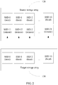
FIG. 2 is a schematic diagram of virtual disk mapping between storage arrays; -
FIG. 3A ,FIG. 3B , andFIG. 3C are a flowchart of a method for migrating data of a source storage array to a target storage array in the prior art; -
FIG. 4 is an architectural diagram of a storage system according toEmbodiment 1 of the present invention; -
FIG. 5 is an architectural diagram of a source storage array according toEmbodiment 1 of the present invention; -
FIG. 6 is a flowchart of a method for allocating access information to a source intelligent network interface card in a source storage array according to an embodiment of the present invention; -
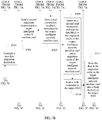
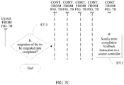
FIG. 7A ,FIG. 7B , andFIG. 7C are a flowchart of a method for migrating data of a source storage array to a target storage array according to an embodiment of the present invention; -
FIG. 8 is an architectural diagram of a storage system according toEmbodiment 2 of the present invention; and -
FIG. 9 is a module diagram of each element in a storage system according to an embodiment of the present invention. - The following clearly and completely describes the technical solutions in the embodiments of the present invention with reference to the accompanying drawings in the embodiments of the present invention. Apparently, the described embodiments are merely some but not all of the embodiments of the present invention.
- As shown in
FIG. 1, FIG. 1 is an architectural diagram of an existing storage system 100. The storage system 100 is a cluster including a plurality of storage arrays connected by using anetwork 110, and is usually used as a data center. For brevity, only two storage arrays are shown in the figure, namely, asource storage array 120 and atarget storage array 130. Thesource storage array 120 is an SSD from which data is migrated, and thetarget storage array 130 is an SSD to which the data is migrated. The storage arrays communicate with each other by using a communications protocol that is based on an RDMA protocol. - Structures of the storage arrays are basically the same. The following uses the
source storage array 120 as an example for description. Thesource storage array 120 includes asource controller 121, asource memory 122, a Peripheral Component Interconnect Express (Peripheral Component Interconnect Express, PCIe)bus 123, a plurality of SSDs (namely, anSSD 0 to an SSD 10), and a network interface card (Network Interface Card, NIC) 125. Thesource memory 122 is connected to thesource controller 121. Thesource controller 121 is connected to the plurality of SSDs and thenetwork interface card 125 by using thePCIe bus 123. Thenetwork interface card 125 is connected to a network interface card of another storage array by using thenetwork 110, to implement communication between thesource storage array 120 and the another storage array such as thetarget storage array 130. - Link initialization is performed when a connection is established between the storage arrays in the storage system 100. During link initialization, based on the RDMA protocol, each storage array can map a local SSD to another storage array in the storage system, so that the another storage array directly accesses the local SSD. The
source storage array 120 and thetarget storage array 130 are used as an example. During link initialization, thetarget storage array 130 maps local SSDs (anSSD 0 to an SSD 10) to thesource storage array 120. In this case, theSSD 0 to theSSD 10 of thetarget storage array 130 may serve asvirtual disks SSD 11 toSSD 21 of thesource storage array 120, to be used by thesource storage array 120. For details, refer toFIG. 4 . A specific method in which thetarget storage array 130 maps the local SSD to thesource storage array 120 to serve as the virtual SSD of the source storage array is as follows: During link initialization, thetarget storage array 130 selects an SSD that needs to be mapped to another storage array for use. In this embodiment, thetarget storage array 130 maps all local SSDs to the another storage array for use, and then sends information about each selected SSD, for example, a disk identifier, a disk size, and address space, to the another storage array such as thesource storage array 120 by using a link to the another storage array. When SSD information sent by each storage array passes through the network interface card (network interface card, NIC) 125 of thesource storage array 120, thenetwork interface card 125 generates an IP address for each SSD, adds the IP address to information about each SSD, and then establishes a correspondence between each IP address and a disk identifier of each SSD. After receiving the information about each SSD, thesource storage array 120 records the IP address of each SSD, identifies each SSD by using the IP address of the SSD, and then creates a disk object for the information about each SSD, that is, the virtual disk (for example, theSSD 11 to theSSD 21 inFIG. 4 ). In this way, the local SSD of thetarget storage array 130 may be mapped to thesource storage array 120, to serve as the virtual disk of thesource storage array 120. When accessing the virtual hard disk, the source storage array only needs to add an IP address of the virtual hard disk to access information. - Another method in which the
target storage array 130 maps the local SSD to thesource storage array 120 to serve as the virtual SSD of the source storage array is as follows: When SSD information sent by each storage array passes through the network interface card (network interface card, NIC) 125 of thesource storage array 120, the network interface card generates an IP address only for thenetwork interface card 135 of thetarget storage array 130. Thesource storage array 120 marks each SSD by using the IP address and a disk identifier, and establishes a disk object. The disk identifier is a unique identifier allocated by each storage array to each SSD in the storage array. In this case, when accessing the virtual hard disk, the source storage array adds the IP address and the disk identifier of the virtual hard disk to the access information. - In actual application, data migration frequently needs to be performed between the storage arrays. For example, when the
source storage array 120 detects a to-be-invalidated SSD, that is, asource SSD 120, data in thesource SSD 120 needs to be migrated to another SSD, to avoid a data loss caused by invalidation of thesource SSD 120. During migration, the data in thesource SSD 120 may be migrated to an SSD of the same storage array or an SSD of another storage array. In this embodiment, only a case in which the data in thesource SSD 120 is migrated to the SSD in the another storage array such as thetarget storage array 130 is described. A hardware structure of thetarget storage array 130 is the same as a hardware structure of thesource storage array 120. In a description process, to differentiate elements included in thetarget storage array 130 from elements included in thesource storage array 120, herein, the elements included in thetarget storage array 130 are respectively referred to as a target controller 131, a target memory 132, and atarget SSD 134. Thetarget SSD 134 is an SSD to which the data in thesource SSD 124 is migrated. - With reference to
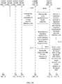
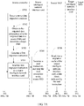
FIG. 3A ,FIG. 3B , andFIG. 3C , the following describes a prior-art method for migrating the data in thesource SSD 124 in thesource storage array 120 to thetarget SSD 134 of thetarget storage array 130. - As shown in
FIG. 3A ,FIG. 3B , andFIG. 3C , in step S201, when detecting that the data in thesource SSD 124 needs to be migrated, for example, detecting that the data of thesource SSD 124 is to be invalidated, thesource controller 121 selects, from the storage system 100, a target SSD to which the data in the source SSD is to be migrated. The target SSD may be a local SSD or a virtual SSD. Herein, only a case in which the target SSD is the virtual SSD is described, that is, a case in which the target SSD is located in a remote storage array. - Step S202: The
source controller 121 applies for migration memory space that is in thesource memory 122 and that is dedicated to data migration, and obtains a data volume of the to-be-migrated data. - Step S203: The
source controller 121 generates a read instruction based on a length of the migration memory space and the obtained data volume of the to-be-migrated data, and sends the read instruction to thesource SSD 124, where the read instruction instructs thesource SSD 124 to migrate a data block whose size is equal to that of the migration memory space. - Step S204: The
source SSD 124 reads, according to the read instruction, a data block that is in the source SSD and that is corresponding to the read instruction into the migration memory space. - Step S205: After completing execution of the read instruction, the
source SSD 124 sends a read completion feedback instruction to thesource controller 121. - Step S206: The
source controller 121 sends a write instruction to the sourcenetwork interface card 125 according to the read completion feedback instruction, where the write instruction instructs the sourcenetwork interface card 125 to migrate data in a migration memory in thesource memory 122 to the target SSD. - Step S207: After receiving the write instruction, the source
network interface card 125 determines a target network interface card based on information about the target SSD in the write instruction, and then forwards the write instruction to the targetnetwork interface card 135. - Step S208: The target
network interface card 135 further forwards the write instruction to the target controller 131. - Step S209: The target controller 131 allocates a migration memory in the target memory 132 according to the write instruction, generates a migration instruction, and sends the migration instruction to the target network interface card, where a source address of the migration instruction is an address of the migration memory in the
source memory 122, and a target address of the migration instruction is an address of the migration memory in the target memory 132. - Step S210: The target
network interface card 135 reads, according to the migration instruction, the data in the migration memory in thesource memory 122 into the target migration memory in the target memory 132. - Step S211: After completing data migration, the target
network interface card 135 informs the target controller that data migration is completed. - Step S212: The target controller sends a write instruction to the target SSD, so that the target SSD writes the data in the target memory into a flash memory of the target SSD.
- Step S213: After receiving a migration completion command sent by the target SSD, the target
network interface card 135 informs the sourcenetwork interface card 125 that data migration is completed, and the sourcenetwork interface card 125 further informs thesource controller 121 that data migration is completed. - Step S214: After receiving the notification command, the
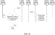
source controller 121 determines whether migration of the to-be-migrated data is completed, where if migration is not completed, a procedure returns to step S201, and the procedure continues being executed until all to-be-migrated data in thesource SSD 124 is migrated; or if migration is completed, the procedure ends. - It may be learned from the foregoing method for migrating data that, in the prior art, when the data in the source SSD is migrated to the target SSD, a data migration process needs to be controlled by the source controller and the target controller, and the migrated data needs to pass through the
source memory 122 and the target memory 132 for migration. In this way, even if bandwidth of the source controller and bandwidth of the target controller that are occupied during data migration are limited, performance of the storage system is still affected. In addition, if the bandwidth of the source controller and the bandwidth of the target controller that are occupied during data migration are limited, a data migration speed is extremely low. This increases a risk of losing migrated data, and further affects reliability of the storage system. - In a method for migrating data provided in an embodiment of the present invention, when data is migrated from a source SSD to a target SSD, the data does not pass through a source memory or a target memory in a migration process, but is directly transmitted by using an interface of a PCIe switch, and a source controller only sends a command related to migration. Therefore, this occupies only little bandwidth of the source controller, and does not affect performance of a storage system. In addition, a data migration speed is not limited by the bandwidth of the source controller, and therefore, the data migration speed is increased. The following describes in detail the solution provided in this embodiment of the present invention.
- As shown in
FIG. 4, FIG. 4 is an architectural diagram of a storage system according toEmbodiment 1 of the present invention. An architecture of the storage system inEmbodiment 1 is basically the same as the architecture of the storage system in the prior art inFIG. 1 , and a difference is that a network device connecting thesource storage array 120 to thetarget storage array 130 is changed from the original network interface card to an intelligent network interface card having a control function. For ease of description, an intelligent network interface card in thesource storage array 120 is referred to as a source intelligentnetwork interface card 126, and an intelligent network interface card in thetarget storage array 130 is referred to as a target intelligentnetwork interface card 136. The source intelligentnetwork interface card 126 and the target intelligentnetwork interface card 136 communicate with each other by using a communications protocol based on an RDMA protocol, such as an NOF protocol. - The
source controller 121 is configured to run anapplication program 1222 in thesource memory 122, to implement some functions provided by thesource storage array 120, for example, control of fetch and migration of data in theSSD 0 to theSSD 10 and control of a data transmission process of the source intelligentnetwork interface card 126. Thesource memory 122 further stores metadata 1221 of theSSD 0 to theSSD 10 and the source intelligentnetwork interface card 126. Themetadata 1221 records information about data stored in each SSD, for example, a data volume of the stored data, logical address information of the stored data, and access information of a migration cache of the source intelligentnetwork interface card 126. The access information of the migration cache is described in detail below. - In this embodiment of the present invention, structures of the
source storage array 120 and thetarget storage array 130 are basically the same. Herein, only thesource storage array 120 is used as an example to describe a structural diagram of each element in the storage array. A structural diagram of the source intelligentnetwork interface card 126 is first described, and a structure of the target intelligentnetwork interface card 136 is the same as a structure of the source intelligentnetwork interface card 126. Herein, only the source intelligentnetwork interface card 126 is used as an example for description. As shown inFIG. 5 , the source intelligentnetwork interface card 126 includes aprocessor 1261 and acache 1262, amigration cache 1263 is further disposed in thecache 1262, and theprocessor 1261 further includes aregister 1264. Thecache 1262 stores a program instruction (not shown in the figure), and theprocessor 1261 executes the program instruction to implement a function indicated by the program instruction. Themigration cache 1263 may be accessed by thesource controller 121 and the SSD. For a method in which themigration cache 1263 is accessed by thesource controller 121 and the SSD, refer to a flowchart shown inFIG. 6 . - Step S601: The source intelligent
network interface card 126 sets cache information of themigration cache 1263 in theregister 1264 of theprocessor 1261. In this embodiment, the cache information includes a size of the migration cache. - Step S602: In a BIOS startup phase of the
source storage array 120, thesource controller 121 reads the cache information of themigration cache 1263 from theregister 1264 of theprocessor 1261 in the intelligentnetwork interface card 126, allocates access information to themigration cache 1263 based on the read cache information, and records, in themetadata 1221 of the source intelligent network interface card in thesource memory 122, the access information allocated to the migration cache, where the access information includes a first access address and a length of the migration cache. The first access address is address information of thesource memory 122, the address information is corresponding to start address information of themigration cache 1263, and access address space of the migration cache may be formed based on the access address and the size of the migration cache. - Step S603: The
source controller 121 writes, into theregister 1264 of the source intelligentnetwork interface card 126, the access information allocated to themigration cache 1263. In specific implementation, only the first access address may be written. - Step S604: The source intelligent
network interface card 126 selects, as themigration cache 1263, cache space whose size is the same as the set cache size from thecache 1262, and establishes a mapping relationship between the access information and themigration cache 1263. - When the source controller 121or another SSD needs to access any location of the
migration cache 1263, as long as an access address of the access address space is added to an access command, a physical address of the migration cache that is corresponding to the access address may be found based on a correspondence between the first access address stored in the register and a start address of themigration cache 1263, to implement access to data in themigration cache 1263. In this way, thesource controller 121 or the SSD may access themigration cache 1263 of the intelligentnetwork interface card 126 by using the access information. After themigration cache 1263 of the intelligentnetwork interface card 126 is determined, data migration may be performed by using themigration cache 1263. - Structures of the SSDs in the
source storage array 120 are also basically the same. Herein, asource SSD 124 is used as an example for description. Thesource SSD 124 includes aprocessor 1241, a direct memory access (Direct Memory Access, DMA)controller 1242, acache 1243, and aflash memory 1244. Theprocessor 1241 is configured to receive a data fetch command sent by thesource controller 121, to control access todata 1246 in theflash memory 1244 according to the fetch command of thesource controller 121. TheDMA controller 1242 may directly access thesource memory 122. In addition, because thesource controller 121 allocates the access information to themigration cache 1263 in the intelligentnetwork interface card 126, theDMA controller 1242 may directly access themigration cache 1263 of the intelligentnetwork interface card 126. A specific access method is further described in detail in the following description of data migration. - After migration caches of the source intelligent
network interface card 126 and the target intelligentnetwork interface card 136 are disposed, data migration may be performed by using the migration caches. A specific migration method is shown inFIG. 7A ,FIG. 7B , andFIG. 7C . - Step S701: The
source controller 121 detects a preset data migration condition. - The preset migration condition may be that an SSD in the
source storage array 126 is determined to be invalidated or when a data migration request is received, the migration request is from an application or another device. - Step S702: When the preset data migration condition is detected, the
source controller 121 obtains to-be-migrated data information of to-be-migrated data in an SSD from which data needs to be migrated, that is, a source SSD, and determines a target SSD. - The target SSD may be a local SSD in
FIG. 2 or a virtual SSD. However, in this embodiment, only a method for migrating data on a premise that the target SSD is a virtual SSD is described. In this embodiment, thevirtual SSD 21 is selected as the target SSD. - The
source controller 121 obtains the to-be-migrated data information of the to-be-migrated data in the source SSD from themetadata 1221 stored in thesource memory 122. The to-be-migrated data information includes a data volume and a logical address of the to-be-migrated data. - The target SSD may be determined by a user, or may be a backup disk disposed for the source SSD in advance. There may be one or more target SSDs, and a specific quantity of target SSDs may be determined according to a data migration speed requirement.
- When determining the target SSD, the user may select the target SSD based on a volume of data stored in each SSD and a busy/idle status of the SSD, that is, may select, as the target SSD, an SSD whose current service volume is relatively small and that has more free space. Generally, a control server (not shown in the figure) is disposed in a storage system. The control server includes current status information of all SSDs in the system, for example, a service volume and free space. All users may select the target SSD by accessing the cluster controller, and the cluster controller sends information about the selected target SSD to the
source storage array 120. - Step S703: The
source controller 121 generates a first migration instruction, where the migration instruction includes information about a to-be-migrated data block in the source SSD, information about the target SSD, and a data length during this migration. - In this implementation, two manners of generating the first migration instruction are provided. The first manner is as follows: The to-be-migrated data is first split into a plurality of data blocks based on a preset data block length during each migration and a preset data volume of the to-be-migrated data that is in the to-be-migrated data information. It should be noted that a length of each data block may be equal to or less than a length of the migration cache. In addition, a logical address of each data block may be determined based on the logical address of the to-be-migrated data and the length of the data block obtained through splitting.
- The second manner is as follows: When the first migration instruction is generated, not all to-be-migrated data is split, but one data block is obtained through splitting only for migration performed once, and a length of the data block obtained through splitting is the preset length, and may be less than or equal to the length of the migration cache; and then a logical address of the data block obtained through splitting is determined, and the first migration instruction is generated for the data block obtained through splitting.
- The first migration instruction includes a source address and a target address, and the source address is a logical address that is of a data block migrated according to the first migration instruction and that is in the source SSD. As described in this embodiment, the target SSD is located in a remote storage array, and based on two mapping manners of the virtual disk described in
FIG. 2 , the target address may be an IP address and a logical address of the SSD, or may be an IP address of the target network interface card and a disk identifier and a logical address of the SSD. - When there are a plurality of determined target SSDs, one data block is separately obtained for each target SSD in ascending order of logical addresses of the to-be-migrated data that are in the source SSD, to generate a plurality of first migration instructions.
- Step S704: The
source controller 121 sends the first migration instruction to the source intelligentnetwork interface card 126. - When generating the plurality of first migration instructions based on the plurality of target SSDs, the
source controller 121 sequentially sends, to the source intelligentnetwork interface card 126, the plurality of first migration instructions based on a generation sequence of the plurality of first migration instructions. - Step S705: When receiving the first migration instruction, the source intelligent
network interface card 126 generates a first read instruction, and sends the first read instruction to the source SSD. The first read instruction includes a source address, a target address, and a length of a migrated data block, the source address is a logical address of the to-be-migrated data block, and the target address is an access address of the migration cache of the intelligent network interface card. - Step S706: When receiving the read instruction, the
source SSD 124 obtains the currently migrated data block from the to-be-migrated data based on the source address and the length of the to-be-migrated data block, and reads the data block into the migration cache of the source intelligentnetwork interface card 126. - In this implementation, after receiving the read instruction, the
processor 1241 of thesource SSD 124 instructs theDMA controller 1242 to find, in the flash memory of the source SSD based on the source address in the read instruction, a to-be-migrated data block corresponding to the source address, and then write, based on the target address, that is, the access address of the migration cache, the to-be-migrated data block into the migration cache of the source intelligentnetwork interface card 126 that is indicated by the target address. When reading the to-be-migrated data block into the migration cache of the intelligentnetwork interface card 126, theDMA controller 1242 first transmits, by using thePCIe bus 123, the to-be-migrated data block and the target address to the migration cache of the source intelligentnetwork interface card 126 that is indicated by the target address, and the source intelligentnetwork interface card 126 further finds, based on the access address in the target address, a physical address of the migration cache that is corresponding to the access address, and then stores the to-be-migrated data block at a location that is in the migration cache and that is indicated by the physical address. - Step S707: After the to-be-migrated data block is fully read into the migration cache of the source intelligent
network interface card 126, thesource SSD 124 sends a read completion feedback instruction to the source intelligentnetwork interface card 126. - Step S708: After receiving the read completion feedback instruction sent by the
source SSD 124, the source intelligentnetwork interface card 126 determines the target intelligentnetwork interface card 136 based on the target address in the first migration instruction, and then sends a second migration instruction to the target intelligentnetwork interface card 136, where the second migration instruction includes a source address and a target address, the source address in the second migration instruction is an access address that is of a physical interval for storing the to-be-migrated data block and that is in the migration cache of the source intelligentnetwork interface card 126, and the target address in the second migration instruction is determined based on the target address in the first migration instruction. - As described in step S703, when the target address in the first migration instruction is the IP address and the logical address of the target SSD, the source intelligent
network interface card 126 may determine the target intelligent network interface card based on the IP address of the target SSD, then determine, based on the IP address and the disk identifier of the SSD that are established during disk mapping, the disk identifier of the target SSD that is corresponding to the IP address of the target SSD, and then use the disk identifier and the logical address as the target address of the second migration instruction. - When the target address in the first migration instruction is the IP address of the target network interface card and the disk identifier and the logical address of the target SSD, the source intelligent
network interface card 126 determines the target network interface card based on the IP address of the target network interface card, and uses the disk identifier and the logical address of the target SSD as the target address of the second migration instruction. - Step S709: The target intelligent
network interface card 136 generates a second read instruction according to the second migration instruction, where a source address of the second read instruction is the source address of the second migration instruction, a target address of the second read instruction is the access address of the migration cache of the target intelligentnetwork interface card 136, and the target intelligentnetwork interface card 136 reads the to-be-migrated data block in the migration cache of the source intelligentnetwork interface card 126 into the migration cache of the target intelligentnetwork interface card 136 according to the second read instruction. - Herein, the target intelligent
network interface card 136 reads the to-be-migrated data block in the migration cache of the source intelligentnetwork interface card 126 by using an RDMA protocol. - Step S710: After the to-be-migrated data block is fully read, the target intelligent
network interface card 136 sends a write instruction to the target SSD, where a source address in the write instruction is the access address of the migration cache of the target intelligent network interface card, and a target address in the write instruction is the target address in the second migration instruction. - As described above, the target address includes the disk identifier and LBA of the target SSD. Therefore, the target intelligent network interface card may find the target SSD based on the disk identifier, and find, based on the LBA, a physical address that is in the flash memory of the target SSD and that is used to store the to-be-migrated data block.
- Step S711: A processor (not shown in the figure) of the
target SSD 134 writes the to-be-migrated data block in the migration cache in the target intelligentnetwork interface card 136 into the flash memory of the target SSD according to the write instruction. - Herein, it should be noted that the
target SSD 134 has a same structure as thesource SSD 124, thetarget SSD 134 also includes a DMA controller (not shown in the figure), and the target SSD writes the to-be-migrated data block in the migration cache of the target intelligentnetwork interface card 136 into the flash memory of the target SSD by using the DMA controller. - Step S712: After completing writing of the to-be-migrated data block, the target intelligent
network interface card 136 sends a write completion feedback instruction to thesource controller 121. - Step S713: After receiving the write completion feedback instruction, the
source controller 121 determines whether migration of the to-be-migrated data in the source SSD is completed. - Step S714: If migration is not completed, the
source controller 121 generates a new migration instruction, and then a procedure returns to step S703; or if migration is completed, a data migration procedure ends. After receiving a plurality of feedback instructions, thesource controller 121 generates one new migration instruction for each feedback instruction. - If the manner of generating the migration instruction in step S703 is the foregoing first manner, in step S714, one data block is determined from data blocks that are still not migrated, and a new read instruction is generated for the determined data block.
- If the manner of generating the read instruction in step S703 is the foregoing second manner, in step 714, one data block is obtained by splitting to-be-migrated data that is still not migrated, and a new read instruction is generated based on the data block newly obtained through splitting.
- In the method provided in the foregoing embodiment, the data in the source SSD may be transmitted to the target SSD without passing through the
source memory 122 or the target memory 132. Therefore, bandwidth of thesource controller 121 is not occupied, and a speed of migrating data between different storage arrays is increased. - In another implementation of the present invention, as shown in
FIG. 8 , the source controller and the source memory form an independent device, that is, ahost 10. Thehost 10 is connected to astorage array 20 by using aPCIe switch 40, and the storage array includes a plurality ofSSDs 30 and an intelligentnetwork interface card 50. In this structure, the source controller still generates and sends a first migration instruction. A structure and an implementation of the intelligentnetwork interface card 50 are the same as those in the first implementation. For details, refer to description inFIG. 6 andFIG. 7A ,FIG. 7B , andFIG. 7C . Details are not described herein again. - In addition, the source intelligent network interface card and the target intelligent network interface card may be field programmable gate arrays (Field Programmable Gate Array, FPGA). In this case, a program in the
cache 1262 is burned on a chip of the field programmable gate array instead of being stored in thecache 1262, and theprocessor 1261 may directly perform the burned program, without a need to invoke the program instruction from thecache 1262 for execution. - As shown in
FIG. 9, FIG. 9 is module diagrams of thesource controller 121 and the source intelligentnetwork interface card 126 in thesource storage array 120 in the storage system shown inFIG. 4 and a function module diagram of the target intelligentnetwork interface card 136 in thetarget storage array 130 in this embodiment. - The
source controller 121 includes agenerating module 901, anallocation module 902, a firstmigration instruction module 903, and a determiningmodule 904. The source intelligentnetwork interface card 126 includes amarking module 905, asetting module 906, amapping module 907, afirst receiving module 908, a readinstruction module 909, and a secondmigration instruction module 910. The target intelligentnetwork interface card 136 includes asetting module 911, amapping module 912, asecond receiving module 913, aread module 914, and awrite instruction module 915. - In actual implementation, structures of storage arrays in the storage system are basically the same, and function modules included in elements of the storage arrays are also basically the same, but functions implemented by the function modules are different when the storage arrays respectively serve as a source end and a destination end. In this embodiment, only a function module implemented when the storage array serves as a source storage array or a target storage array is described.
- When link initialization is performed on each storage array of the storage system, the marking
module 905 of the source intelligent network interface card generates identification information of the target intelligent network interface card based on SSD information sent by the target intelligent network interface card. In this case, the identification information may be an IP address allocated to each SSD or an IP address allocated to the target intelligent network interface card. For details, refer to related description inFIG. 2 . After receiving information about each SSD that is sent by the source intelligent network interface card, thegenerating module 901 of the source controller generates a virtual disk of the source storage array based on the information about each SSD. For a specific generation process, refer to related description inFIG. 2 . - The
setting module 906 of the source intelligent network interface card cooperates with theallocation module 902 of the source controller, to implement a function of allowing the source controller and the SSD to access the migration cache in the source intelligent network interface card. This is corresponding to the method of providing the migration cache by the source intelligent network interface card shown inFIG. 6 . Specifically, thesetting module 905 of the source intelligent network interface card is configured to set cache information of the migration cache in the register of the source intelligent network interface card. For a specific setting manner, refer to description of step S601. - The
allocation module 902 of the source controller is configured to: read the migration cache information of the source intelligent network interface card in the register of the processor of the source intelligent network interface card in a BIOS startup phase of the source storage array, allocate access information to the migration cache of the source intelligent network interface card based on the read migration cache information, record, in metadata, the access information allocated to the source intelligent network interface card, and write, into the register of the source intelligent network interface card, the access information allocated to the migration cache of the source intelligent network interface card. For a specific allocation manner, refer to description of step S602. - The
mapping module 907 of the source intelligent network interface card is configured to: select, as the migration cache, cache space whose size is the same as a set cache size from the cache, and establish a mapping relationship between the access information and the migration cache. This is corresponding to step S604. - A function executed by the
setting module 910 and themapping module 911 of the target intelligent network interface card are the same as a function executed by thesetting module 906 and themapping module 907 of the source intelligent network interface card, that is, setting the migration cache for the target intelligent network interface card. For details, refer to related description of setting the migration cache of the source intelligent network interface card. Details are not described herein again. - The first
migration instruction module 903 of the source controller is configured to: detect a preset data migration condition, and when the preset data migration condition is detected, obtain to-be-migrated data information of to-be-migrated data in a source SSD, determine a target SSD, then generate a first migration instruction based on the to-be-migrated data information of the to-be-migrated data and information about the target SSD, and send the first migration instruction to the source intelligent network interface card. A function executed by the firstmigration instruction module 903 is corresponding to steps S701 to S704 inFIG. 7A ,FIG. 7B , andFIG. 7C . Two manners of generating the first migration instruction are the same as those in step S703. Details are not described herein again. - The
first receiving module 908 is configured to receive the first migration instruction, and the readinstruction module 909 of the source intelligent network interface card generates a read instruction according to the first migration instruction, to instruct the source SSD to read the to-be-migrated data in the source SSD into the migration cache of the source intelligent network interface card. For details, refer to description of steps S705 to S707 inFIG. 7A ,FIG. 7B , andFIG. 7C . - After the to-be-migrated data is migrated to the migration cache of the source intelligent network interface card, the second
migration instruction module 910 of the source intelligent network interface card sends a second migration instruction to the target intelligent network interface card. For details, refer to description of step S708 inFIG. 7A ,FIG. 7B , andFIG. 7C . - The
second receiving module 913 of the target intelligent network interface card receives the second migration instruction, and theread module 914 of the target intelligent network interface card generates a second read instruction according to the second migration instruction, and executes the generated second read instruction to read the to-be-migrated data in the migration cache of the source intelligent network interface card into the migration cache of the target intelligent network interface card. For details, refer to description of step S709 inFIG. 7A ,FIG. 7B , andFIG. 7C . - After the to-be-migrated data is migrated to the migration cache of the target intelligent network interface card, the
write instruction module 915 of the target intelligent network interface card sends a write instruction to the target SSD, to instruct the target SSD to write the to-be-migrated data in the target intelligent network interface card into a flash memory of the target SSD. For details, refer to steps S710 to S712 inFIG. 7A ,FIG. 7B , andFIG. 7C . - After the to-be-migrated data block is written into the flash memory of the target SSD, the determining module of the source controller further determines whether migration of the to-be-migrated data in the source SSD is completed. If migration is not completed, a new migration instruction is generated to continue performing migration until all to-be-migrated data in the source SSD is migrated; or if migration is completed, a migration procedure ends. For details, refer to description of step S713 in
FIG. 7A ,FIG. 7B , andFIG. 7C . - As shown in
FIG. 5 , the cache of the source intelligent network interface card further stores a program instruction (not shown in the figure), and the processor of the source intelligent network interface card executes the program instruction to implement corresponding steps executed by the source intelligent network interface card in the flowchart shown inFIG. 7A ,FIG. 7B , andFIG. 7C . Likewise, the cache of the target intelligent network interface card also stores a program instruction (not shown in the figure), and the processor of the target intelligent network interface card executes the program instruction to implement corresponding steps executed by the target intelligent network interface card in the flowchart shown inFIG. 7A ,FIG. 7B , andFIG. 7C . - The technology for migrating data between storage arrays provided in the embodiments of the present invention is described in detail above. The principle and implementation of the present invention are described herein by using specific examples. The description of the foregoing embodiments is merely intended to help understand the method and core ideas of the present invention.
Claims (21)
- A method for migrating data, applied to a source storage array, wherein the source storage array comprises a source network interface card and a source solid state disk, SSD, the source network interface card comprises a source migration cache, and the source SSD accesses the source migration cache based on access information of the source migration cache; and
the method is performed by the source network interface card, and the method comprises:receiving a first migration instruction, wherein the first migration instruction carries an address of to-be-migrated data in the source SSD and information about a target SSD to which the to-be-migrated data is to be migrated, and the target SSD belongs to a target storage array;sending a read instruction to the source SSD, wherein the read instruction comprises the address of the to-be-migrated data in the source SSD and the access information of the source migration cache, and the read instruction is used to instruct the source SSD to read the to-be-migrated data into the source migration cache; andsending a second migration instruction to a target network interface card of the target storage array, wherein the second migration instruction comprises the access information of the source migration cache and an address of the target SSD that is determined based on the information about the target SSD, the access information of the source migration cache comprises information about the to-be-migrated data stored in the source migration cache, and the second migration instruction is used to instruct the target network interface card to migrate the to-be-migrated data in the source migration cache to the target storage array. - The method for migrating data according to claim 1, wherein the access information of the source migration cache comprises a memory address allocated by a controller of the source storage array to the source migration cache.
- The method for migrating data according to claim 1 or 2, wherein the information about the target SSD comprises an IP address of the target SSD, and the IP address of the target SSD is an IP address allocated by the source network interface card to the target SSD when a connection is established between the target storage array and the source storage array; and
before the sending a second migration instruction to a target network interface card of the target storage array, the method further comprises:
determining the target network interface card based on the IP address that is in the information about the target SSD and that is of the target SSD. - The method for migrating data according to claim 3, wherein the source network interface card stores a mapping relationship between the IP address of the target SSD and a disk identifier of the target SSD;
the information about the target SSD further comprises a logical address for storing the to-be-migrated data in the target SSD; and the method further comprises:determining the disk identifier of the target SSD based on the mapping relationship and the IP address that is in the information about the target SSD and that is of the target SSD; andusing, as the address of the target SSD, the disk identifier of the target SSD and the logical address for storing the to-be-migrated data in the target SSD. - The method for migrating data according to claim 1 or 2, wherein the information about the target SSD comprises an IP address of the target network interface card, and the IP address of the target network interface card is an IP address allocated by the source network interface card to the target network interface card when a connection is established between the target storage array and the source storage array; and
the source network interface card determines the target network interface card based on the IP address that is in the information about the target SSD and that is of the target network interface card. - The method for migrating data according to claim 5, wherein the information about the target SSD further comprises a disk identifier of the target SSD and a logical address for storing the to-be-migrated data in the target SSD; and
determining the address of the target SSD based on the information about the target SSD comprises:
using, as the address of the target SSD, the disk identifier of the target SSD and the logical address for storing the to-be-migrated data. - A method for migrating data, applied to a target storage array, wherein the target storage array comprises a target network interface card and a target SSD, the target network interface card comprises a target migration cache, and the target SSD accesses the target migration cache based on access information of the target migration cache; and
the method is performed by the target intelligent network interface card, and the method comprises:receiving a migration instruction sent by a source network interface card of a source storage array, wherein the migration instruction comprises access information of a source migration cache of the source network interface card and an address of the target SSD, and the access information of the source migration cache comprises information about to-be-migrated data that is stored in the source migration cache and that is migrated from a source SSD;reading the to-be-migrated data in the source migration cache into the target migration cache according to the migration instruction; andsending a write instruction to the target SSD, wherein the write instruction comprises the access information of the target migration cache and the address of the target SSD, and the write instruction is used to instruct the target SSD to write the to-be-migrated data in the target migration cache into the target SSD. - The method for migrating data according to claim 7, wherein the access information comprises a controller memory address allocated by a controller of the target storage array to the target migration cache.
- The method for migrating data according to claim 7 or 8, wherein the reading the to-be-migrated data in the source migration cache into the target migration cache according to the migration instruction comprises:
generating a read instruction according to the migration instruction, wherein a source address of the read instruction is the access information of the source migration cache in the migration instruction, and a target address of the read instruction is the access information of the target migration cache. - The method for migrating data according to any one of claims 7 to 9, wherein information about the target SSD comprises a disk identifier of the target SSD; and
the sending a write instruction to the target SSD comprises:determining, by the target network interface card, the target SSD from a plurality of SSDs of the target storage array based on the disk identifier of the target SSD; andsending the write instruction to the target SSD. - A source network interface card, wherein a source storage array comprises the source network interface card and a source SSD, the source network interface card comprises a source migration cache, and the source SSD accesses the source migration cache based on access information of the source migration cache; and
the source network interface card comprises:a receiving module, configured to receive a first migration instruction, wherein the first migration instruction carries an address of to-be-migrated data in the source SSD and information about a target SSD to which the to-be-migrated data is to be migrated;a read instruction module, configured to send a read instruction to the source SSD, wherein the read instruction comprises the address of the to-be-migrated data in the source SSD and the access information of the source migration cache, and the read instruction is used to instruct the source SSD to read the to-be-migrated data into the source migration cache; anda migration instruction module, configured to send a second migration instruction to a target network interface card of a target storage array, wherein the second migration instruction comprises the access information of the source migration cache and an address of the target SSD that is determined based on the information about the target SSD, the access information of the source migration cache comprises information about the to-be-migrated data stored in the source migration cache, and the second migration instruction is used to instruct the target network interface card to migrate the to-be-migrated data in the source migration cache to the target storage array. - The source network interface card according to claim 11, wherein the access information of the source migration cache comprises a memory address allocated by a controller of the source storage array to the source migration cache.
- The source network interface card according to claim 11 or 12, wherein the information about the target SSD comprises an IP address of the target SSD, and the IP address of the target SSD is an IP address allocated by the source network interface card to the target SSD when a connection is established between the target storage array and the source storage array; and
before sending the second migration instruction to the target network interface card of the target storage array, the migration instruction module is further configured to determine the target network interface card based on the IP address that is in the information about the target SSD and that is of the target SSD. - The source network interface card according to claim 13, wherein the source network interface card stores a mapping relationship between the IP address of the target SSD and a disk identifier of the target SSD;
the information about the target SSD further comprises a logical address of the target SSD; and
when determining the address of the target SSD based on the information about the target SSD, the migration instruction module determines the disk identifier of the target SSD based on the mapping relationship and the IP address that is in the information about the target SSD and that is of the target SSD, and uses the disk identifier and the logical address of the target SSD as the address of the target SSD. - The source network interface card according to claim 11 or 12, wherein the information about the target SSD comprises an IP address of the target network interface card, and the IP address of the target network interface card is an IP address allocated by the source network interface card to the target network interface card when a connection is established between the target storage array and the source storage array; and
before sending the second migration instruction to the target network interface card of the target storage array, the migration instruction module is further configured to determine the target network interface card based on the IP address that is in the information about the target SSD and that is of the target network interface card. - The source network interface card for migrating data according to claim 15, wherein the information about the target SSD further comprises a disk identifier of the target SSD and a logical address for storing the to-be-migrated data in the target SSD; and
when determining the address of the target SSD based on the information about the target SSD, the migration module uses, as the address of the target SSD, the disk identifier of the target SSD and the logical address for storing the to-be-migrated data in the target SSD. - A target network interface card, wherein a target storage array comprises the target network interface card and a target SSD, the target network interface card comprises a target migration cache, and the target SSD accesses the target migration cache based on access information of the target migration cache; and
the target network interface card comprises:a receiving module, configured to receive a migration instruction sent by a source network interface card of a source storage array, wherein the migration instruction comprises access information of a source migration cache of the source network interface card and an address of the target SSD, and the source migration cache stores to-be-migrated data migrated from a source SSD;a read module, configured to read the to-be-migrated data in the source migration cache into the target migration cache according to the migration instruction; anda write instruction module, configured to send a write instruction to the target SSD, wherein the write instruction comprises the access information of the target migration cache and the address of the target SSD, and the write instruction is used to instruct the target SSD to write the to-be-migrated data in the target migration cache into the target SSD. - The target network interface card according to claim 17, wherein the access information of the target migration cache comprises memory address space allocated by a controller of the target storage array to the target migration cache.
- The target network interface card according to claim 17 or 18, wherein when reading the to-be-migrated data in the source migration cache into the target migration cache according to the migration instruction, the read instruction module is configured to:generate a read instruction according to the migration instruction, wherein a source address of the read instruction is the access information of the source migration cache in the migration instruction, and a target address of the read instruction is the access information of the target migration cache; andread the to-be-migrated data in the source migration cache into the target migration cache according to the read instruction.
- The target network interface card according to any one of claims 17 to 19, wherein information about the target SSD comprises a disk identifier of the target SSD; and
before sending the write instruction to the target SSD, the write instruction module is further configured to determine the target SSD from a plurality of SSDs of the target array based on the disk identifier of the target SSD. - A system for migrating data, comprising a source network interface card and a target network interface card, wherein the source network interface card and a source solid state disk SSD belong to a source storage array and are interconnected, the target network interface card and a target SSD belong to a target storage array and are interconnected, the source network interface card comprises a source migration cache, the source migration cache comprises access information, the source SSD accesses the source migration cache based on the access information, the target network interface card comprises a target migration cache, the target migration cache comprises access information, and the target SSD accesses the target migration cache based on the access information;
the source network interface card is configured to:receive a first migration instruction, wherein the first migration instruction carries an address of to-be-migrated data in the source SSD and information about a target SSD to which the to-be-migrated data is to be migrated, and the target SSD belongs to the target storage array;send a read instruction to the source SSD, wherein the read instruction comprises an address of the source SSD that is carried in the first migration instruction and the access information of the source migration cache, and the read instruction is used to instruct the source SSD to read the to-be-migrated data into the source migration cache; andsend a second migration instruction to the target network interface card of the target storage array, wherein the second migration instruction comprises the access information of the source migration cache and an address of the target SSD that is determined based on the information about the target SSD; andthe target network interface card is configured to:receive the second migration instruction, and read the to-be-migrated data in the source migration cache into the target migration cache according to the second migration instruction; andsend a write instruction to the target SSD, wherein the write instruction comprises information about the target migration cache and the address of the target SSD, and is used to instruct the target SSD to write the to-be-migrated data in the target migration cache into the target SSD.
Priority Applications (1)
| Application Number | Priority Date | Filing Date | Title |
|---|---|---|---|
| EP21174867.8A EP3929756A1 (en) | 2017-09-05 | 2017-09-05 | Method, system, and intelligent network interface card for migrating data |
Applications Claiming Priority (1)
| Application Number | Priority Date | Filing Date | Title |
|---|---|---|---|
| PCT/CN2017/100586 WO2019047026A1 (en) | 2017-09-05 | 2017-09-05 | Data migration method and system and intelligent network card |
Related Child Applications (2)
| Application Number | Title | Priority Date | Filing Date |
|---|---|---|---|
| EP21174867.8A Division-Into EP3929756A1 (en) | 2017-09-05 | 2017-09-05 | Method, system, and intelligent network interface card for migrating data |
| EP21174867.8A Division EP3929756A1 (en) | 2017-09-05 | 2017-09-05 | Method, system, and intelligent network interface card for migrating data |
Publications (3)
| Publication Number | Publication Date |
|---|---|
| EP3663928A1 EP3663928A1 (en) | 2020-06-10 |
| EP3663928A4 EP3663928A4 (en) | 2020-09-02 |
| EP3663928B1 true EP3663928B1 (en) | 2021-06-23 |
Family
ID=65633432
Family Applications (2)
| Application Number | Title | Priority Date | Filing Date |
|---|---|---|---|
| EP21174867.8A Pending EP3929756A1 (en) | 2017-09-05 | 2017-09-05 | Method, system, and intelligent network interface card for migrating data |
| EP17924034.6A Active EP3663928B1 (en) | 2017-09-05 | 2017-09-05 | Data migration method and system and intelligent network card |
Family Applications Before (1)
| Application Number | Title | Priority Date | Filing Date |
|---|---|---|---|
| EP21174867.8A Pending EP3929756A1 (en) | 2017-09-05 | 2017-09-05 | Method, system, and intelligent network interface card for migrating data |
Country Status (4)
| Country | Link |
|---|---|
| US (1) | US11966612B2 (en) |
| EP (2) | EP3929756A1 (en) |
| CN (2) | CN109791522B (en) |
| WO (1) | WO2019047026A1 (en) |
Families Citing this family (9)
| Publication number | Priority date | Publication date | Assignee | Title |
|---|---|---|---|---|
| US11068365B2 (en) * | 2018-08-23 | 2021-07-20 | Micron Technology, Inc. | Data recovery within a memory sub-system without moving or processing the data through a host |
| CN112578997B (en) * | 2019-09-30 | 2022-07-22 | 华为云计算技术有限公司 | Data migration method, system and related equipment |
| KR20220055034A (en) * | 2020-10-26 | 2022-05-03 | 삼성전자주식회사 | Method of operating storage device and method of operating storage system using the same |
| KR20220059266A (en) * | 2020-11-02 | 2022-05-10 | 에스케이하이닉스 주식회사 | Storage system |
| CN112559245A (en) * | 2020-12-01 | 2021-03-26 | 深圳市欧瑞博科技股份有限公司 | Data migration method and device for intelligent gateway, server and storage medium |
| CN113220346A (en) * | 2021-04-29 | 2021-08-06 | 上海阵量智能科技有限公司 | Hardware circuit, data moving method, chip and electronic equipment |
| CN115374024A (en) * | 2021-05-21 | 2022-11-22 | 华为技术有限公司 | Memory data sorting method and related equipment |
| CN114489517B (en) * | 2022-02-14 | 2023-09-08 | 苏州浪潮智能科技有限公司 | Offline acceleration migration method, system, equipment and storage medium |
| CN117573043A (en) * | 2024-01-17 | 2024-02-20 | 济南浪潮数据技术有限公司 | Transmission method, device, system, equipment and medium for distributed storage data |
Family Cites Families (20)
| Publication number | Priority date | Publication date | Assignee | Title |
|---|---|---|---|---|
| US8782199B2 (en) * | 1997-10-14 | 2014-07-15 | A-Tech Llc | Parsing a packet header |
| CN1282326C (en) * | 2003-12-10 | 2006-10-25 | 中国科学院计算技术研究所 | Method of user level parallel communication between computers based on intelligent network card |
| US20070041383A1 (en) * | 2005-04-05 | 2007-02-22 | Mohmmad Banikazemi | Third party node initiated remote direct memory access |
| CN101702688B (en) * | 2009-11-24 | 2012-01-04 | 武汉绿色网络信息服务有限责任公司 | Data package transmit-receive method |
| CN102244579B (en) * | 2010-05-12 | 2013-10-30 | 北京研华兴业电子科技有限公司 | Network interface card and method for receiving network data |
| US8555019B2 (en) * | 2010-09-08 | 2013-10-08 | International Business Machines Corporation | Using a migration cache to cache tracks during migration |
| CN103080895B (en) * | 2010-12-22 | 2016-01-27 | 株式会社日立制作所 | Comprise the storage system of multiple memory storages with both Storage Virtualization function and capacity virtualization |
| CN102651690B (en) * | 2011-02-28 | 2015-11-25 | 国际商业机器公司 | To the method and apparatus that shared drive controls |
| US20130042238A1 (en) * | 2011-08-12 | 2013-02-14 | International Business Machines Corporation | Optimized Virtual Function Translation Entry Memory Caching |
| KR101861170B1 (en) * | 2011-08-17 | 2018-05-25 | 삼성전자주식회사 | Memory system including migration manager |
| CN102333037A (en) * | 2011-10-20 | 2012-01-25 | 中兴通讯股份有限公司 | Method and device for migrating virtual machine |
| CN103970481B (en) | 2013-01-29 | 2017-03-01 | 国际商业机器公司 | The method and apparatus rebuilding memory array |
| US10382401B1 (en) * | 2013-02-26 | 2019-08-13 | Zentera Systems, Inc. | Cloud over IP for enterprise hybrid cloud network and security |
| WO2014141411A1 (en) * | 2013-03-13 | 2014-09-18 | 株式会社日立製作所 | Storage system and method for controlling storage system |
| WO2015198441A1 (en) * | 2014-06-26 | 2015-12-30 | 株式会社日立製作所 | Computer system, management computer, and management method |
| US9195402B1 (en) * | 2014-07-15 | 2015-11-24 | Oracle International Corporation | Target and initiator mode configuration of tape drives for data transfer between source and destination tape drives |
| US10162558B2 (en) * | 2015-10-30 | 2018-12-25 | Micron Technology, Inc. | Data transfer techniques for multiple devices on a shared bus |
| US10447800B2 (en) * | 2015-12-17 | 2019-10-15 | Dell Products L.P. | Network cache deduplication analytics based compute cluster load balancer |
| WO2018102969A1 (en) * | 2016-12-05 | 2018-06-14 | 华为技术有限公司 | Control method, device and system for data reading-writing command in nvme over fabric architecture |
| CN108228647B (en) * | 2016-12-21 | 2022-05-24 | 伊姆西Ip控股有限责任公司 | Method and apparatus for data copying |
-
2017
- 2017-09-05 CN CN201780002932.1A patent/CN109791522B/en active Active
- 2017-09-05 WO PCT/CN2017/100586 patent/WO2019047026A1/en unknown
- 2017-09-05 EP EP21174867.8A patent/EP3929756A1/en active Pending
- 2017-09-05 EP EP17924034.6A patent/EP3663928B1/en active Active
- 2017-09-05 CN CN202110043788.4A patent/CN112835817A/en active Pending
-
2020
- 2020-03-04 US US16/809,026 patent/US11966612B2/en active Active
Non-Patent Citations (1)
| Title |
|---|
| None * |
Also Published As
| Publication number | Publication date |
|---|---|
| CN109791522A (en) | 2019-05-21 |
| US20200233601A1 (en) | 2020-07-23 |
| EP3663928A1 (en) | 2020-06-10 |
| EP3663928A4 (en) | 2020-09-02 |
| CN109791522B (en) | 2021-01-15 |
| WO2019047026A1 (en) | 2019-03-14 |
| CN112835817A (en) | 2021-05-25 |
| US11966612B2 (en) | 2024-04-23 |
| EP3929756A1 (en) | 2021-12-29 |
Similar Documents
| Publication | Publication Date | Title |
|---|---|---|
| EP3663928B1 (en) | Data migration method and system and intelligent network card | |
| US11644994B2 (en) | Data migration method, host, and solid state disk | |
| KR102457611B1 (en) | Method and apparatus for tenant-aware storage sharing platform | |
| JPWO2017145272A1 (en) | Data migration method and computer system | |
| US11966585B2 (en) | Storage device and storage system | |
| CN116032930A (en) | Network storage method, storage system, data processing unit and computer system | |
| US9319350B2 (en) | Virtual address for virtual port | |
| US20210311654A1 (en) | Distributed Storage System and Computer Program Product | |
| US20150363346A1 (en) | Sata initiator addressing and storage device slicing | |
| US11496563B2 (en) | System and method for migrating volumes between storage appliances | |
| US9501290B1 (en) | Techniques for generating unique identifiers | |
| US10705905B2 (en) | Software-assisted fine-grained data protection for non-volatile memory storage devices | |
| JP7482905B2 (en) | STORAGE SYSTEM, MEMORY MANAGEMENT METHOD, AND MANAGEMENT NODE | |
| US20230359379A1 (en) | Computing system generating map data, and method of operating the same | |
| EP4206935A1 (en) | Storage device, operation method of storage device, and storage system using the same | |
| WO2023046129A1 (en) | Computer device, method for processing data, and computer system | |
| US20230359394A1 (en) | Operating method of memory device for managing map data of each of plurality of storage devices, computing system including memory device, and operating method of computing system | |
| WO2014115184A1 (en) | Storage system and control method for storage system | |
| KR20140015857A (en) | Computing device and virtual device controlling method for controlling virtual device by computing system |
Legal Events
| Date | Code | Title | Description |
|---|---|---|---|
| STAA | Information on the status of an ep patent application or granted ep patent |
Free format text: STATUS: THE INTERNATIONAL PUBLICATION HAS BEEN MADE |
|
| PUAI | Public reference made under article 153(3) epc to a published international application that has entered the european phase |
Free format text: ORIGINAL CODE: 0009012 |
|
| STAA | Information on the status of an ep patent application or granted ep patent |
Free format text: STATUS: REQUEST FOR EXAMINATION WAS MADE |
|
| 17P | Request for examination filed |
Effective date: 20200303 |
|
| AK | Designated contracting states |
Kind code of ref document: A1 Designated state(s): AL AT BE BG CH CY CZ DE DK EE ES FI FR GB GR HR HU IE IS IT LI LT LU LV MC MK MT NL NO PL PT RO RS SE SI SK SM TR |
|
| AX | Request for extension of the european patent |
Extension state: BA ME |
|
| A4 | Supplementary search report drawn up and despatched |
Effective date: 20200731 |
|
| RIC1 | Information provided on ipc code assigned before grant |
Ipc: G06F 3/06 20060101ALI20200727BHEP Ipc: G06F 12/0871 20160101AFI20200727BHEP Ipc: G06F 12/0868 20160101ALI20200727BHEP Ipc: H04L 29/08 20060101ALI20200727BHEP Ipc: G06F 12/02 20060101ALI20200727BHEP |
|
| DAV | Request for validation of the european patent (deleted) | ||
| DAX | Request for extension of the european patent (deleted) | ||
| GRAP | Despatch of communication of intention to grant a patent |
Free format text: ORIGINAL CODE: EPIDOSNIGR1 |
|
| STAA | Information on the status of an ep patent application or granted ep patent |
Free format text: STATUS: GRANT OF PATENT IS INTENDED |
|
| INTG | Intention to grant announced |
Effective date: 20210115 |
|
| GRAS | Grant fee paid |
Free format text: ORIGINAL CODE: EPIDOSNIGR3 |
|
| GRAA | (expected) grant |
Free format text: ORIGINAL CODE: 0009210 |
|
| STAA | Information on the status of an ep patent application or granted ep patent |
Free format text: STATUS: THE PATENT HAS BEEN GRANTED |
|
| AK | Designated contracting states |
Kind code of ref document: B1 Designated state(s): AL AT BE BG CH CY CZ DE DK EE ES FI FR GB GR HR HU IE IS IT LI LT LU LV MC MK MT NL NO PL PT RO RS SE SI SK SM TR |
|
| REG | Reference to a national code |
Ref country code: GB Ref legal event code: FG4D |
|
| REG | Reference to a national code |
Ref country code: CH Ref legal event code: EP |
|
| REG | Reference to a national code |
Ref country code: DE Ref legal event code: R096 Ref document number: 602017041052 Country of ref document: DE Ref country code: AT Ref legal event code: REF Ref document number: 1404896 Country of ref document: AT Kind code of ref document: T Effective date: 20210715 |
|
| REG | Reference to a national code |
Ref country code: IE Ref legal event code: FG4D |
|
| REG | Reference to a national code |
Ref country code: LT Ref legal event code: MG9D |
|
| PG25 | Lapsed in a contracting state [announced via postgrant information from national office to epo] |
Ref country code: BG Free format text: LAPSE BECAUSE OF FAILURE TO SUBMIT A TRANSLATION OF THE DESCRIPTION OR TO PAY THE FEE WITHIN THE PRESCRIBED TIME-LIMIT Effective date: 20210923 Ref country code: HR Free format text: LAPSE BECAUSE OF FAILURE TO SUBMIT A TRANSLATION OF THE DESCRIPTION OR TO PAY THE FEE WITHIN THE PRESCRIBED TIME-LIMIT Effective date: 20210623 Ref country code: FI Free format text: LAPSE BECAUSE OF FAILURE TO SUBMIT A TRANSLATION OF THE DESCRIPTION OR TO PAY THE FEE WITHIN THE PRESCRIBED TIME-LIMIT Effective date: 20210623 Ref country code: LT Free format text: LAPSE BECAUSE OF FAILURE TO SUBMIT A TRANSLATION OF THE DESCRIPTION OR TO PAY THE FEE WITHIN THE PRESCRIBED TIME-LIMIT Effective date: 20210623 |
|
| REG | Reference to a national code |
Ref country code: AT Ref legal event code: MK05 Ref document number: 1404896 Country of ref document: AT Kind code of ref document: T Effective date: 20210623 |
|
| PG25 | Lapsed in a contracting state [announced via postgrant information from national office to epo] |
Ref country code: SE Free format text: LAPSE BECAUSE OF FAILURE TO SUBMIT A TRANSLATION OF THE DESCRIPTION OR TO PAY THE FEE WITHIN THE PRESCRIBED TIME-LIMIT Effective date: 20210623 Ref country code: RS Free format text: LAPSE BECAUSE OF FAILURE TO SUBMIT A TRANSLATION OF THE DESCRIPTION OR TO PAY THE FEE WITHIN THE PRESCRIBED TIME-LIMIT Effective date: 20210623 Ref country code: NO Free format text: LAPSE BECAUSE OF FAILURE TO SUBMIT A TRANSLATION OF THE DESCRIPTION OR TO PAY THE FEE WITHIN THE PRESCRIBED TIME-LIMIT Effective date: 20210923 Ref country code: LV Free format text: LAPSE BECAUSE OF FAILURE TO SUBMIT A TRANSLATION OF THE DESCRIPTION OR TO PAY THE FEE WITHIN THE PRESCRIBED TIME-LIMIT Effective date: 20210623 Ref country code: GR Free format text: LAPSE BECAUSE OF FAILURE TO SUBMIT A TRANSLATION OF THE DESCRIPTION OR TO PAY THE FEE WITHIN THE PRESCRIBED TIME-LIMIT Effective date: 20210924 |
|
| REG | Reference to a national code |
Ref country code: NL Ref legal event code: MP Effective date: 20210623 |
|
| PG25 | Lapsed in a contracting state [announced via postgrant information from national office to epo] |
Ref country code: EE Free format text: LAPSE BECAUSE OF FAILURE TO SUBMIT A TRANSLATION OF THE DESCRIPTION OR TO PAY THE FEE WITHIN THE PRESCRIBED TIME-LIMIT Effective date: 20210623 Ref country code: ES Free format text: LAPSE BECAUSE OF FAILURE TO SUBMIT A TRANSLATION OF THE DESCRIPTION OR TO PAY THE FEE WITHIN THE PRESCRIBED TIME-LIMIT Effective date: 20210623 Ref country code: SK Free format text: LAPSE BECAUSE OF FAILURE TO SUBMIT A TRANSLATION OF THE DESCRIPTION OR TO PAY THE FEE WITHIN THE PRESCRIBED TIME-LIMIT Effective date: 20210623 Ref country code: SM Free format text: LAPSE BECAUSE OF FAILURE TO SUBMIT A TRANSLATION OF THE DESCRIPTION OR TO PAY THE FEE WITHIN THE PRESCRIBED TIME-LIMIT Effective date: 20210623 Ref country code: AT Free format text: LAPSE BECAUSE OF FAILURE TO SUBMIT A TRANSLATION OF THE DESCRIPTION OR TO PAY THE FEE WITHIN THE PRESCRIBED TIME-LIMIT Effective date: 20210623 Ref country code: CZ Free format text: LAPSE BECAUSE OF FAILURE TO SUBMIT A TRANSLATION OF THE DESCRIPTION OR TO PAY THE FEE WITHIN THE PRESCRIBED TIME-LIMIT Effective date: 20210623 Ref country code: PT Free format text: LAPSE BECAUSE OF FAILURE TO SUBMIT A TRANSLATION OF THE DESCRIPTION OR TO PAY THE FEE WITHIN THE PRESCRIBED TIME-LIMIT Effective date: 20211025 Ref country code: NL Free format text: LAPSE BECAUSE OF FAILURE TO SUBMIT A TRANSLATION OF THE DESCRIPTION OR TO PAY THE FEE WITHIN THE PRESCRIBED TIME-LIMIT Effective date: 20210623 Ref country code: RO Free format text: LAPSE BECAUSE OF FAILURE TO SUBMIT A TRANSLATION OF THE DESCRIPTION OR TO PAY THE FEE WITHIN THE PRESCRIBED TIME-LIMIT Effective date: 20210623 |
|
| PG25 | Lapsed in a contracting state [announced via postgrant information from national office to epo] |
Ref country code: PL Free format text: LAPSE BECAUSE OF FAILURE TO SUBMIT A TRANSLATION OF THE DESCRIPTION OR TO PAY THE FEE WITHIN THE PRESCRIBED TIME-LIMIT Effective date: 20210623 |
|
| REG | Reference to a national code |
Ref country code: DE Ref legal event code: R097 Ref document number: 602017041052 Country of ref document: DE |
|
| PG25 | Lapsed in a contracting state [announced via postgrant information from national office to epo] |
Ref country code: DK Free format text: LAPSE BECAUSE OF FAILURE TO SUBMIT A TRANSLATION OF THE DESCRIPTION OR TO PAY THE FEE WITHIN THE PRESCRIBED TIME-LIMIT Effective date: 20210623 |
|
| PLBE | No opposition filed within time limit |
Free format text: ORIGINAL CODE: 0009261 |
|
| REG | Reference to a national code |
Ref country code: CH Ref legal event code: PL |
|
| STAA | Information on the status of an ep patent application or granted ep patent |
Free format text: STATUS: NO OPPOSITION FILED WITHIN TIME LIMIT |
|
| REG | Reference to a national code |
Ref country code: BE Ref legal event code: MM Effective date: 20210930 |
|
| 26N | No opposition filed |
Effective date: 20220324 |
|
| PG25 | Lapsed in a contracting state [announced via postgrant information from national office to epo] |
Ref country code: MC Free format text: LAPSE BECAUSE OF FAILURE TO SUBMIT A TRANSLATION OF THE DESCRIPTION OR TO PAY THE FEE WITHIN THE PRESCRIBED TIME-LIMIT Effective date: 20210623 Ref country code: AL Free format text: LAPSE BECAUSE OF FAILURE TO SUBMIT A TRANSLATION OF THE DESCRIPTION OR TO PAY THE FEE WITHIN THE PRESCRIBED TIME-LIMIT Effective date: 20210623 |
|
| PG25 | Lapsed in a contracting state [announced via postgrant information from national office to epo] |
Ref country code: LU Free format text: LAPSE BECAUSE OF NON-PAYMENT OF DUE FEES Effective date: 20210905 Ref country code: IT Free format text: LAPSE BECAUSE OF FAILURE TO SUBMIT A TRANSLATION OF THE DESCRIPTION OR TO PAY THE FEE WITHIN THE PRESCRIBED TIME-LIMIT Effective date: 20210623 Ref country code: IE Free format text: LAPSE BECAUSE OF NON-PAYMENT OF DUE FEES Effective date: 20210905 Ref country code: BE Free format text: LAPSE BECAUSE OF NON-PAYMENT OF DUE FEES Effective date: 20210930 |
|
| PG25 | Lapsed in a contracting state [announced via postgrant information from national office to epo] |
Ref country code: LI Free format text: LAPSE BECAUSE OF NON-PAYMENT OF DUE FEES Effective date: 20210930 Ref country code: CH Free format text: LAPSE BECAUSE OF NON-PAYMENT OF DUE FEES Effective date: 20210930 |
|
| PG25 | Lapsed in a contracting state [announced via postgrant information from national office to epo] |
Ref country code: CY Free format text: LAPSE BECAUSE OF FAILURE TO SUBMIT A TRANSLATION OF THE DESCRIPTION OR TO PAY THE FEE WITHIN THE PRESCRIBED TIME-LIMIT Effective date: 20210623 |
|
| PG25 | Lapsed in a contracting state [announced via postgrant information from national office to epo] |
Ref country code: HU Free format text: LAPSE BECAUSE OF FAILURE TO SUBMIT A TRANSLATION OF THE DESCRIPTION OR TO PAY THE FEE WITHIN THE PRESCRIBED TIME-LIMIT; INVALID AB INITIO Effective date: 20170905 |
|
| PGFP | Annual fee paid to national office [announced via postgrant information from national office to epo] |
Ref country code: GB Payment date: 20230803 Year of fee payment: 7 |
|
| PGFP | Annual fee paid to national office [announced via postgrant information from national office to epo] |
Ref country code: FR Payment date: 20230808 Year of fee payment: 7 Ref country code: DE Payment date: 20230802 Year of fee payment: 7 |
|
| PG25 | Lapsed in a contracting state [announced via postgrant information from national office to epo] |
Ref country code: MK Free format text: LAPSE BECAUSE OF FAILURE TO SUBMIT A TRANSLATION OF THE DESCRIPTION OR TO PAY THE FEE WITHIN THE PRESCRIBED TIME-LIMIT Effective date: 20210623 |