EP3660531A1 - Method and circuit for checking the plausibility of a current sensor measurement result - Google Patents
Method and circuit for checking the plausibility of a current sensor measurement result Download PDFInfo
- Publication number
- EP3660531A1 EP3660531A1 EP19216038.0A EP19216038A EP3660531A1 EP 3660531 A1 EP3660531 A1 EP 3660531A1 EP 19216038 A EP19216038 A EP 19216038A EP 3660531 A1 EP3660531 A1 EP 3660531A1
- Authority
- EP
- European Patent Office
- Prior art keywords
- electrical
- circuit
- current
- change
- current sensor
- Prior art date
- Legal status (The legal status is an assumption and is not a legal conclusion. Google has not performed a legal analysis and makes no representation as to the accuracy of the status listed.)
- Withdrawn
Links
- 238000005259 measurement Methods 0.000 title claims abstract description 28
- 238000000034 method Methods 0.000 title claims abstract description 25
- 230000001419 dependent effect Effects 0.000 claims description 3
- 238000011161 development Methods 0.000 description 10
- 230000018109 developmental process Effects 0.000 description 10
- 238000011156 evaluation Methods 0.000 description 6
- 230000003071 parasitic effect Effects 0.000 description 6
- 238000004590 computer program Methods 0.000 description 5
- 230000007547 defect Effects 0.000 description 4
- 239000012535 impurity Substances 0.000 description 4
- 230000002950 deficient Effects 0.000 description 1
- 238000001514 detection method Methods 0.000 description 1
- 238000010586 diagram Methods 0.000 description 1
- 230000006870 function Effects 0.000 description 1
- 238000004519 manufacturing process Methods 0.000 description 1
- 238000000691 measurement method Methods 0.000 description 1
- 238000012545 processing Methods 0.000 description 1
Images


Classifications
-
- G—PHYSICS
- G01—MEASURING; TESTING
- G01R—MEASURING ELECTRIC VARIABLES; MEASURING MAGNETIC VARIABLES
- G01R19/00—Arrangements for measuring currents or voltages or for indicating presence or sign thereof
- G01R19/0092—Arrangements for measuring currents or voltages or for indicating presence or sign thereof measuring current only
-
- G—PHYSICS
- G01—MEASURING; TESTING
- G01R—MEASURING ELECTRIC VARIABLES; MEASURING MAGNETIC VARIABLES
- G01R31/00—Arrangements for testing electric properties; Arrangements for locating electric faults; Arrangements for electrical testing characterised by what is being tested not provided for elsewhere
- G01R31/005—Testing of electric installations on transport means
- G01R31/006—Testing of electric installations on transport means on road vehicles, e.g. automobiles or trucks
-
- G—PHYSICS
- G01—MEASURING; TESTING
- G01R—MEASURING ELECTRIC VARIABLES; MEASURING MAGNETIC VARIABLES
- G01R35/00—Testing or calibrating of apparatus covered by the other groups of this subclass
-
- G—PHYSICS
- G01—MEASURING; TESTING
- G01R—MEASURING ELECTRIC VARIABLES; MEASURING MAGNETIC VARIABLES
- G01R1/00—Details of instruments or arrangements of the types included in groups G01R5/00 - G01R13/00 and G01R31/00
- G01R1/20—Modifications of basic electric elements for use in electric measuring instruments; Structural combinations of such elements with such instruments
- G01R1/203—Resistors used for electric measuring, e.g. decade resistors standards, resistors for comparators, series resistors, shunts
Definitions
- the invention relates to a circuit for conducting an electrical current between a vehicle battery and an electrical network component that can be connected to the vehicle battery via an electrical component and a vehicle with the circuit.
- a current sensor can be connected in series between the electrical energy source and the electrical consumer.
- a current sensor is for example from the DE 10 2011 078 548 A1 known.
- the specified method is based on the consideration that current sensors should be electrically connected in series between the electrical energy source and the electrical consumer in order to conduct the entire electrical charge to be transported with the electrical current via the current sensor. Based on this consideration, the specified method is based on the knowledge that defects in the electrical circuit in which the current sensor is implemented or defects in the current sensor itself, such as, for example, parasitic short circuits, can lead to part of the electrical current and thus to the electrical charge is led past the current sensor and cannot be detected by the current sensor, which leads to an incorrect measurement with the current sensor. In order to avoid such an incorrect measurement, it is proposed with the stated method to bring the electrical circuit into a state in which the electrical current is known or at least can be derived from the state. In this way, the correct functioning of the current sensor in the electrical system can be ensured.
- the current sensor can also be monitored for its error-free functionality by the individual shunts connected in parallel, the values of which should be known, for example, from the manufacture, because if one shunt is switched off, the current in the other must be switched off Change the shunt in a manner known to the person skilled in the art, which can be verified accordingly.
- the electrical circuit is in an at least quasi-stationary state before the electrical consumer is switched on.
- a quasi-steady state is to be understood below to mean a state in which the state of the electrical circuit changes within a predetermined time limit only within a predetermined range. In a steady state, the state of the electrical circuit would not change at all. In this way it can be ensured that the predetermined A change in the circuit state is not overlaid with an unknown change in the circuit state, as a result of which the electric current would change in an unknown manner and the plausibility of the measurement results with the current sensor would thus be impossible.
- the known current consumption of the known electrical consumer is dependent on operating conditions of the electrical circuit and / or of the electrical consumer. This development is based on the consideration that the electrical resistance of the known electrical consumer influences the electrical current to be measured. However, this electrical resistance depends on the operating conditions of the electrical circuit with the current sensor. Taking these operating conditions into account in the specified method therefore improves the plausibility check of the measurement results.
- the operating conditions include an operating voltage dropping at the known electrical consumer and / or an operating temperature of the known electrical consumer and / or the circuit.
- This development is based on the consideration that not all operating conditions have an influence on the electrical resistance of the electrical circuit in the same way. In order not to unnecessarily complicate the determination of the known current consumption, only the operating conditions should therefore have an influence on the known current consumption, which noticeably change the known current consumption, that is to say outside of certain predefinable tolerance values.
- This development of the specified method is based on the consideration that the first predetermined change in the circuit state itself could also be faulty because, for example, a defective consumer is applied to the circuit to change the circuit state. Then the plausibility check of the measurement results could be either positive or negative. In order to intercept this case, it is proposed with the development of the specified method that the measurement results obtained by the first predetermined change in the circuit state are directly or indirectly checked for plausibility with a further previously known change in the circuit state.
- the second predetermined change in the circuit state of the electrical circuit can be carried out alternatively or in addition to the circuit state of the electrical circuit after the first predetermined change in the circuit state of the electrical circuit.
- a control device is specified which is set up to carry out one of the specified methods.
- the specified control device has a memory and a processor.
- the specified method is stored in the memory in the form of a computer program and the processor is provided for executing the method when the computer program is loaded from the memory into the processor.
- the invention also relates to a computer program with program code means for all steps of one of the specified Procedure to be performed when the computer program is executed on a computer or one of the specified devices.
- the invention also relates to a computer program product which contains a program code which is stored on a computer-readable data carrier and which, if it is executed on a data processing device, carries out one of the methods specified.
- FIG. 1 shows a schematic view of a current sensor 2 between two line sections 4, 6.
- the current sensor 2 is intended to detect an electrical current 7 which flows through the two line sections 4, 6 via the current sensor 2.
- the current sensor 2 is designed as a passive shunt, which is a simple electrical resistance with a predetermined resistance value in a manner known to the person skilled in the art.
- the current sensor 2 can also act as an active shunt, such as from the DE 10 2011 078 548 A1 known, or be based on a magnetic measuring principle and is in no way limited in its structure.
- the current sensor 2 is received on the butt end between the two line sections 4, 6, electrical contact lines 8, 10, which are led to an evaluation circuit 12, being electrically contacted at the connection points between the line sections 4, 6 and the current sensor 2.
- a measuring voltage 14 drops between the measuring lines 8, 10 in a manner known to the person skilled in the art. From the measurement voltage 14 and the known resistance value of the current sensor 2, which is designed as a passive shunt, the current 7 to be detected can be inferred in a manner known to those skilled in the art.
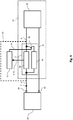
- FIG. 2 shows a schematic view of the current sensor 2 in a circuit 22.
- the current sensor 2 is connected between an electrical energy source 24 designed as a battery and an electrical consumer 26, the electrical current 7 to be detected being conducted to the current sensor 2 via a first battery pole 28 of the battery 24 and one of the two line sections 4 .
- the current 7 to be detected is then conducted to the electrical consumer 26 via the other of the two line sections 6 and returns from the electrical consumer to the battery 24 via a return line 30 and a second battery pole 32.
- the current sensor 2 is connected to the evaluation circuit 12 via measuring lines 8, 10, the measuring lines 8, 10 being able to transmit the voltage drop 14 across the current sensor 2 but also other signals necessary for the measurement, such as a control signal with which the voltage drop 14 at one active shunt can be kept constant.
- a control signal with which the voltage drop 14 at one active shunt can be kept constant please refer to the DE 10 2011 078 548 A1 referred.
- the evaluation circuit 12 outputs a state change signal 34 with which it can change a circuit state of the circuit 22.
- the circuit state can be any influencing variable that changes the electrical current 7 to be detected.
- Such influencing variables can be, for example, the wiring of the circuit 22 or one that acts on the circuit 22 Be temperature that change the electric current 7 to be detected.
- the state of the electrical circuit 22 is changed with the state change signal 34 such that the electrical current 7 to be detected changes in a known manner.
- the in Fig. 1 change shown measuring current 20 flowing through the current sensor 2 in the known manner. If he does not do so, some of the electrical current 7 to be detected flows via a defect in the circuit 22, such as the impurity 18 as a parasitic current 16, so that the measuring current 20 is falsified.
- the evaluation circuit 12 can therefore plausibility check the measurement current 20 detected with the current sensor 2.
- the current sensor 2 is constructed via two individual shunts 36, 38 connected in parallel, the second individual shunt 38 being able to be removed from the parallel connection via a switch 40 which can be controlled by the status change signal 34.
- the evaluation circuit first detects the current 7 to be recorded via the measuring current 20 with both individual shunts 36, 38 in the common parallel connection and stores the value of the measuring current 20, for example, in an internal memory (not shown). It then disconnects the second individual shunt 38 from the parallel connection via the status change signal 34 and detects the value of the measurement current 20 again.
- the two recorded values now depend on one another in a manner known to the person skilled in the art.
- the resistance value of the two individual shunts 36, 38 is the same, for example, the value of the measuring current 20 would have to be doubled after the second individual shunt 38 was switched off. If it does not, a parasitic current 18 flows.
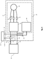
- the electrical consumer 26 comprises a three-phase electric motor 42, which is supplied with electrical energy from the battery 24 via a converter 44 in a manner known to the person skilled in the art.
- a single-phase current sensor 46 can be arranged in each phase in order to carry out measurement tasks known to the person skilled in the art, such as, for example, the detection of the magnetic stator field.
- an electric heater 48 is connected in parallel to the converter 44, which can be separated from the parallel connection via the switch 40 which can be switched by means of the status change signal 34.
- the evaluation device 20 can switch on the electrical heater 48 and measure the value by which the measuring current 20 has risen through the current sensor 20. This value must match the current consumption of the electrical heater 48. If it does not, part of the current 7 to be detected flows as a parasitic current 18.
- the single-phase current sensors 46 can also be checked for their fault-free function using the method presented in the present application.
- Fig. 5 Referred to a qualitative Course 50 of the measuring current 18 over time 52, which with the in Fig. 4 shown arrangement is included.
- the electrical heater 48 is preferably switched on as an additional electrical consumer at a start time 54 when the measurement current 20 has settled to a stationary first value 56.
- the measurement current 20 rises and swings to a second stationary value 58, which can be measured at the earliest at a time 60 at which this settling is complete.
- the time between these two times is usually in the range of seconds.
- the amount 62 should correspond to the difference between the two values 58 and 56 of the measurement current 20 of the current consumption of the electrical heater.
Landscapes
- Physics & Mathematics (AREA)
- General Physics & Mathematics (AREA)
- Chemical & Material Sciences (AREA)
- Engineering & Computer Science (AREA)
- Combustion & Propulsion (AREA)
- Measurement Of Current Or Voltage (AREA)
Abstract
Es wird ein Verfahren zum Plausibilisieren eines Messergebnisses für einen elektrischen Strom (20) durch einen in einer elektrischen Schaltung (22) verschalteten Stromsensor (2) vorgeschlagen, wobei der Stromsensor (2) wenigstens zwei parallel geschaltete Shunts (36, 38) aufweist, umfassend:- Durchführen einer vorbestimmten Veränderung (34) am Schaltungszustand der elektrischen Schaltung (22) durch elektrisches Entfernen ein Shunt (38) aus der Schaltung (22);- Erfassen einer durch die Veränderung (34) des Schaltungszustands hervorgerufene Veränderung (62) des elektrischen Stromes (20) durch den Stromsensor (2) als Messergebnis; und- Plausibilisieren des Messergebnisses durch Gegenüberstellen der Veränderung (34) des Schaltungszustandes und der Veränderung (62) des elektrischen Stromes (20).A method for plausibility checking of a measurement result for an electrical current (20) by a current sensor (2) connected in an electrical circuit (22) is proposed, the current sensor (2) comprising at least two shunts (36, 38) connected in parallel : - performing a predetermined change (34) in the circuit state of the electrical circuit (22) by electrically removing a shunt (38) from the circuit (22); - detecting a change (62) in the electrical state caused by the change (34) in the circuit state Current (20) through the current sensor (2) as a measurement result; and- plausibility of the measurement result by comparing the change (34) in the circuit state and the change (62) in the electrical current (20).
Description
Die Erfindung betrifft eine Schaltung zum Leiten eines elektrischen Stromes zwischen einer Fahrzeugbatterie und einer an die Fahrzeugbatterie anschließbaren elektrischen Netzwerkkomponente über ein elektrisches Bauelement sowie ein Fahrzeug mit der Schaltung.The invention relates to a circuit for conducting an electrical current between a vehicle battery and an electrical network component that can be connected to the vehicle battery via an electrical component and a vehicle with the circuit.
Zur Durchführung von Messungen eines von einer elektrischen Energiequelle an einen elektrischen Verbraucher abgegebenen elektrischen Stromes in einem Kraftfahrzeug können in Reihe zwischen die elektrische Energiequelle und den elektrischen Verbraucher ein Stromsensor geschaltet werden. Ein derartiger Stromsensor ist beispielsweise aus der
Es ist Aufgabe der vorliegenden Erfindung bekannte Strommessverfahren zu verbessern.It is an object of the present invention to improve known current measurement methods.
Die Aufgabe wird durch die Merkmale der unabhängigen Ansprüche gelöst. Bevorzugte Weiterbildungen sind Gegenstand der abhängigen Ansprüche.The object is solved by the features of the independent claims. Preferred developments are the subject of the dependent claims.
Gemäß einem Aspekt der Erfindung umfasst ein Verfahren zum Plausibilisieren eines Messergebnisses eines in einer elektrischen Schaltung verschalteten Stromsensors, wobei der Stromsensor wenigstens zwei parallel geschaltete Shunts aufweist, die folgenden Schritte:
- Durchführen einer vorbestimmten Veränderung am Schaltungszustand der elektrischen Schaltung durch elektrisches Entfernen ein Shunt aus der Schaltung;
- Erfassen einer durch die Veränderung des Schaltungszustands hervorgerufene Veränderung des elektrischen Stromes; und
- Plausibilisieren der Messergebnisse des Stromsensors durch Gegenüberstellen der Veränderung des Schaltungszustandes und der Veränderung des elektrischen Stromes.
- Performing a predetermined change in the circuit state of the electrical circuit by electrically removing a shunt from the circuit;
- Detecting a change in the electrical current caused by the change in the circuit state; and
- Plausibility check of the measurement results of the current sensor by comparing the change in the circuit state and the change in the electrical current.
Dem angegebenen Verfahren liegt die Überlegung zugrunde, dass Stromsensoren elektrisch in Reihe zwischen die elektrische Energiequelle und den elektrischen Verbraucher geschalten sollten, um die gesamte mit dem elektrischen Strom zu transportierende elektrische Ladung über den Stromsensor zu führen. Basierend auf dieser Überlegung liegt dem angegebenen Verfahren die Erkenntnis zugrunde, dass Defekte in der elektrischen Schaltung, in der der Stromsensor implementiert ist, oder Defekte im Stromsensor selbst, wie beispielsweise parasitäre Kurzschlüsse, dazu führen können, dass ein Teil des elektrischen Stromes und damit der elektrischen Ladung am Stromsensor vorbei geführt wird und durch den Stromsensor nicht erfasst werden kann, was zu einer Fehlmessung mit dem Stromsensor führt. Um eine derartige Fehlmessung zu vermeiden, wird mit dem angegebenen Verfahren vorgeschlagen, die elektrische Schaltung in einen derartigen Zustand zu überführen, in dem der elektrische Strom bekannt ist oder wenigstens aus dem Zustand abgeleitet werden kann. So kann die fehlerfreie Funktion des Stromsensors in der elektrischen sichergestellt werden.The specified method is based on the consideration that current sensors should be electrically connected in series between the electrical energy source and the electrical consumer in order to conduct the entire electrical charge to be transported with the electrical current via the current sensor. Based on this consideration, the specified method is based on the knowledge that defects in the electrical circuit in which the current sensor is implemented or defects in the current sensor itself, such as, for example, parasitic short circuits, can lead to part of the electrical current and thus to the electrical charge is led past the current sensor and cannot be detected by the current sensor, which leads to an incorrect measurement with the current sensor. In order to avoid such an incorrect measurement, it is proposed with the stated method to bring the electrical circuit into a state in which the electrical current is known or at least can be derived from the state. In this way, the correct functioning of the current sensor in the electrical system can be ensured.
Des Weiteren liegt die Überlegung zugrunde, dass der Stromsensor auch durch die einzelnen parallel geschalteten Shunts, dessen Werte beispielsweise durch die Herstellung bekannt sein müssten, auf seine fehlerfreie Funktionalität hin überwacht werden kann, denn wenn ein Shunt abgeschaltet wird, muss sich der Strom im anderen Shunt in einer dem Fachmann bekannten Weise ändern, was entsprechend verifiziert werden kann.Furthermore, it is based on the consideration that the current sensor can also be monitored for its error-free functionality by the individual shunts connected in parallel, the values of which should be known, for example, from the manufacture, because if one shunt is switched off, the current in the other must be switched off Change the shunt in a manner known to the person skilled in the art, which can be verified accordingly.
In einer zusätzlichen Weiterbildung des angegebenen Verfahrens befindet sich die elektrische Schaltung vor dem Zuschalten des elektrischen Verbrauchers in einem wenigstens quasistationären Zustand. Unter einem quasistationären Zustand soll nachstehend ein Zustand verstanden werden, bei dem sich der Zustand der elektrischen Schaltung innerhalb einer vorbestimmten Zeitschranke nur innerhalb eines vorbestimmten Bereichs ändert. In einem stationären Zustand würde sich der Zustand der elektrischen Schaltung überhaupt nicht ändern. Auf diese Weise kann sichergestellt werden, dass sich die vorbestimmte Veränderung am Schaltungszustand nicht mit einer unbekannten Veränderung des Schaltungszustandes überlagert, wodurch sich der elektrische Strom in unbekannter Weise verändern würde und so eine Plausibilisierung der Messergebnisse mit dem Stromsensor unmöglich wäre.In an additional development of the specified method, the electrical circuit is in an at least quasi-stationary state before the electrical consumer is switched on. A quasi-steady state is to be understood below to mean a state in which the state of the electrical circuit changes within a predetermined time limit only within a predetermined range. In a steady state, the state of the electrical circuit would not change at all. In this way it can be ensured that the predetermined A change in the circuit state is not overlaid with an unknown change in the circuit state, as a result of which the electric current would change in an unknown manner and the plausibility of the measurement results with the current sensor would thus be impossible.
In einer noch anderen Weiterbildung des angegebenen Verfahrens ist die bekannte Stromaufnahme des bekannten elektrischen Verbrauchers von Betriebsbedingungen der elektrischen Schaltung und/oder des elektrischen Verbrauchers abhängig. Dieser Weiterbildung liegt die Überlegung zugrunde, dass der elektrische Widerstand des bekannten elektrischen Verbrauchers den zu messenden elektrischen Strom beeinflusst. Dieser elektrische Widerstand ist jedoch von den Betriebsbedingungen der elektrischen Schaltung mit dem Stromsensor abhängig. Eine Berücksichtigung dieser Betriebsbedingungen im angegebenen Verfahren verbessert daher die Plausibilisierung der Messergebnisse.In yet another development of the specified method, the known current consumption of the known electrical consumer is dependent on operating conditions of the electrical circuit and / or of the electrical consumer. This development is based on the consideration that the electrical resistance of the known electrical consumer influences the electrical current to be measured. However, this electrical resistance depends on the operating conditions of the electrical circuit with the current sensor. Taking these operating conditions into account in the specified method therefore improves the plausibility check of the measurement results.
In einer bevorzugten Weiterbildung umfassen die Betriebsbedingungen eine am bekannten elektrischen Verbraucher abfallende Betriebsspannung und/oder eine Betriebstemperatur des bekannten elektrischen Verbrauchers und/oder der Schaltung. Dieser Weiterbildung liegt die Überlegung zugrunde, dass nicht alle Betriebsbedingungen in gleicher Weise einen Einfluss auf den elektrischen Widerstand der elektrischen Schaltung haben. Um die Bestimmung der bekannten Stromaufnahme nicht unnötig zu verkomplizieren sollten daher nur die Betriebsbedingungen einen Einfluss auf die bekannten Stromaufnahme haben, die die bekannte Stromaufnahme spürbar verändern, das heißt außerhalb bestimmter vorgebbarer Toleranzwerte.In a preferred development, the operating conditions include an operating voltage dropping at the known electrical consumer and / or an operating temperature of the known electrical consumer and / or the circuit. This development is based on the consideration that not all operating conditions have an influence on the electrical resistance of the electrical circuit in the same way. In order not to unnecessarily complicate the determination of the known current consumption, only the operating conditions should therefore have an influence on the known current consumption, which noticeably change the known current consumption, that is to say outside of certain predefinable tolerance values.
In einer alternativen Weiterbildung umfasst das angegebene Verfahren die Schritte:
- Durchführen einer zweiten vorbestimmten Veränderung am Schaltungszustand der elektrischen Schaltung;
- Erfassen einer durch die zweite Veränderung des Schaltungszustands hervorgerufene zweite Veränderung des elektrischen Stromes; und
- Gegenüberstellen der Veränderung des Schaltungszustandes und der Veränderung des elektrischen Stromes.
- Making a second predetermined change in the circuit state of the electrical circuit;
- Detecting a second change in the circuit caused by the second change in the circuit state electric current; and
- Contrasting the change in the circuit state and the change in the electrical current.
Dieser Weiterbildung des angegebenen Verfahrens liegt die Überlegung zugrunde, dass auch die erste vorbestimmte Veränderung des Schaltungszustandes selbst fehlerhaft sein könnte, weil beispielsweise zur Veränderung des Schaltungszustandes ein defekter Verbraucher an die Schaltung angelegt wird. Dann könnte die Plausibilisierung der Messergebnisse fälschlicherweise entweder positiv oder negativ ausfallen. Um diesen Fall abzufangen wird mit der Weiterbildung des angegebenen Verfahrens vorgeschlagen, die durch die erste vorbestimmte Veränderung des Schaltungszustandes erhaltenen Messergebnisse direkt oder indirekt mit einer weiteren vorbekannten Veränderung des Schaltungszustandes zu plausibilisieren.This development of the specified method is based on the consideration that the first predetermined change in the circuit state itself could also be faulty because, for example, a defective consumer is applied to the circuit to change the circuit state. Then the plausibility check of the measurement results could be either positive or negative. In order to intercept this case, it is proposed with the development of the specified method that the measurement results obtained by the first predetermined change in the circuit state are directly or indirectly checked for plausibility with a further previously known change in the circuit state.
Dabei kann die zweite vorbestimmte Veränderung am Schaltungszustand der elektrischen Schaltung gemäß einer besonderen Weiterbildung des angegebenen Verfahrens nach der ersten vorbestimmten Veränderung am Schaltungszustand der elektrischen Schaltung alternativ oder zusätzlich zu dieser durchgeführt.In this case, the second predetermined change in the circuit state of the electrical circuit can be carried out alternatively or in addition to the circuit state of the electrical circuit after the first predetermined change in the circuit state of the electrical circuit.
Gemäß einem weiteren Aspekt der Erfindung ist eine Steuervorrichtung angegeben, die eingerichtet ist, eines der angegebenen Verfahren durchzuführen.According to a further aspect of the invention, a control device is specified which is set up to carry out one of the specified methods.
In einer Weiterbildung der Erfindung weist die angegebene Steuervorrichtung einen Speicher und einen Prozessor auf. Dabei ist das angegebene Verfahren in Form eines Computerprogramms in dem Speicher hinterlegt und der Prozessor zur Ausführung des Verfahrens vorgesehen, wenn das Computerprogramm aus dem Speicher in den Prozessor geladen ist.In one development of the invention, the specified control device has a memory and a processor. The specified method is stored in the memory in the form of a computer program and the processor is provided for executing the method when the computer program is loaded from the memory into the processor.
Die Erfindung betrifft auch ein Computerprogramm mit Programmcodemitteln, um alle Schritte eines der angegebenen Verfahren durchzuführen, wenn das Computerprogramm auf einem Computer oder einer der angegebenen Vorrichtungen ausgeführt wird.The invention also relates to a computer program with program code means for all steps of one of the specified Procedure to be performed when the computer program is executed on a computer or one of the specified devices.
Die Erfindung betrifft auch ein Computerprogrammprodukt, das einen Programmcode enthält, der auf einem computerlesbaren Datenträger gespeichert ist und der, wenn er auf einer Datenverarbeitungseinrichtung ausgeführt wird, eines der angegebenen Verfahren durchführt.The invention also relates to a computer program product which contains a program code which is stored on a computer-readable data carrier and which, if it is executed on a data processing device, carries out one of the methods specified.
Gemäß einem weiteren Aspekt der Erfindung umfasst eine Fahrzeugbatterie
- einen Batteriepol zum Abgeben eines elektrischen Stromes an einen elektrischen Verbraucher,
- einen an den Batteriepol angeschlossenen Stromsensor zum Erfassen des elektrischen Stromes und
- eine der angegebenen Steuervorrichtung zum Plausibilisieren eines Messergebnisses des Stromsensors, die an den Stromsensor angeschlossen ist.
- a battery pole for delivering an electrical current to an electrical consumer,
- a current sensor connected to the battery pole for detecting the electrical current and
- one of the specified control device for checking the plausibility of a measurement result of the current sensor, which is connected to the current sensor.
Die oben beschriebenen Eigenschaften, Merkmale und Vorteile dieser Erfindung sowie die Art und Weise, wie diese erreicht werden, werden klarer und deutlicher verständlich im Zusammenhang mit der folgenden Beschreibung der Ausführungsbeispiele, die im Zusammenhang mit den Zeichnungen näher erläutert werden, wobei:
-
Fig. 1 eine schematische Ansicht eines Stromsensors zwischen zwei Leitungsabschnitten, -
Fig. 2 eine schematische Ansicht eines Stromsensors in einer Schaltung, -
Fig. 3 eine schematische Ansicht eines alternativen Stromsensors in einer Schaltung, -
Fig. 4 eine schematische Ansicht eines Stromsensors in einer alternativen Schaltung, und -
Fig. 5 ein Stromverlauf-Diagramm mit Messergebnissen eines Stromsensors zeigen.
-
Fig. 1 1 shows a schematic view of a current sensor between two line sections, -
Fig. 2 1 shows a schematic view of a current sensor in a circuit, -
Fig. 3 1 shows a schematic view of an alternative current sensor in a circuit, -
Fig. 4 a schematic view of a current sensor in an alternative circuit, and -
Fig. 5 show a current profile diagram with measurement results of a current sensor.
In den Figuren werden gleiche technische Elemente mit gleichen Bezugszeichen versehen und nur einmal beschrieben.In the figures, the same technical elements are provided with the same reference symbols and described only once.
Es wird auf
Der Stromsensor 2 ist in der vorliegenden Ausbildung als passiver Shunt ausgeführt, der in einer dem Fachmann bekannten Weise ein einfacher elektrischer Widerstand mit einem vorgegebenen Widerstandswert ist. Der Stromsensor 2 kann jedoch auch als aktiver Shunt, wie beispielsweise aus der
In der vorliegenden Ausführung ist der Stromsensor 2 stoßseitig zwischen den beiden Leitungsabschnitten 4, 6 aufgenommen, wobei an den Verbindungspunkten zwischen den Leitungsabschnitten 4, 6 und dem Stromsensor 2 elektrische Messleitungen 8, 10 elektrisch kontaktiert sind, die zu einer Auswerteschaltung 12 geführt sind. Zwischen den Messleitungen 8, 10 fällt in einer dem Fachmann bekannten Weise eine Messspannung 14 ab. Aus der Messspannung 14 und dem bekannten Widerstandswert des als passiver Shunt ausgebildeten Stromsensors 2 kann in einer dem Fachmann bekannten Weise auf den zu erfassenden Strom 7 geschlossen werden.In the present embodiment, the
Wird der Stromsensor 2 jedoch beispielsweise von einer Verunreinigung 16 überbrückt, so fließt ein Teil des zu erfassenden Stromes 7 nicht über den Stromsensor 2 sondern als parasitärer Strom 18 über diese Verunreinigung 16, wodurch der mit dem Stromsensor 2 erfasste Messstrom 20 um diesen parasitären Strom 18 verfälscht wird. Da sich derartige Verunreinigungen 16 oder andere Defekte am Stromsensor selbst oder an einer den Stromsensor 2 enthaltenden Schaltung erst im Laufe ihres Einsatzes ergeben, sollten diese auch im Laufe ihres Einsatzes erfasst werden. Dazu werden nachstehend Lösungsmöglichkeiten angeboten.However, if the
Es wird auf
In der vorliegenden Ausführung ist der Stromsensor 2 zwischen eine als Batterie ausgeführte elektrische Energiequelle 24 und einen elektrischen Verbraucher 26 geschaltet, wobei der zu erfassende elektrische Strom 7 über einen ersten Batteriepol 28 der Batterie 24 und einen der beiden Leitungsabschnitte 4 an den Stromsensor 2 geleitet wird. Der zu erfassende Strom 7 wird dann über den anderen der beiden Leitungsabschnitte 6 an den elektrischen Verbraucher 26 geleitet und kehrt vom elektrischen Verbraucher über eine Rückleitung 30 und einen zweiten Batteriepol 32 in die Batterie 24 zurück.In the present embodiment, the
Der Stromsensor 2 ist über Messleitungen 8, 10 mit der Auswerteschaltung 12 verbunden, wobei die Messleitungen 8, 10 den Spannungsabfall 14 über dem Stromsensor 2 aber auch weitere zur Messung notwendige Signale, wie beispielsweise ein Regelungssignal übermitteln können, mit dem der Spannungsabfall 14 bei einem aktiven Shunt konstant gehalten werden kann. Zu weiteren Informationen dazu wird auf die
In der vorliegenden Ausführung gibt die Auswerteschaltung 12 ein Zustandsänderungssignal 34 aus, mit dem sie einen Schaltungszustand der Schaltung 22 verändern kann. Der Schaltungszustand kann dabei jede beliebige Einflussgröße sein, die den zu erfassenden elektrischen Strom 7 verändert. Derartige Einflussgrößen können beispielsweise die Verdrahtung der Schaltung 22 oder eine auf die Schaltung 22 einwirkende Temperatur sein, die den zu erfassenden elektrischen Strom 7 verändern.In the present embodiment, the
In der vorliegenden Ausführung wird der Zustand der elektrischen Schaltung 22 mit dem Zustandsänderungssignal 34 so verändert, dass sich der zu erfassende elektrische Strom 7 in einer bekannten Weise verändert. Damit muss sich auch der in
Nachstehend sollen dazu zwei Beispiele diskutiert werden.Two examples will be discussed below.
Es wird auf
In der vorliegenden Ausführung ist der Stromsensor 2 über zwei parallelgeschaltete Einzelshunts 36, 38 aufgebaut, wobei der zweite Einzelshunt 38 über einen durch das Zustandsänderungssignal 34 steuerbaren Schalter 40 aus der Parallelschaltung entfernt werden kann.In the present embodiment, the
Im Einsatz erfasst die Auswerteschaltung den zu erfassenden Strom 7 über den Messstrom 20 zunächst mit beiden Einzelshunts 36, 38 in der gemeinsamen Parallelschaltung und speichert sich den Wert des Messstroms 20 beispielsweise in einem nicht weiter dargestellten internen Speicher. Danach trennt sie den zweiten Einzelshunt 38 aus der Parallelschaltung über das Zustandsänderungssignal 34 und erfasst den Wert des Messstroms 20 erneut.In use, the evaluation circuit first detects the current 7 to be recorded via the measuring current 20 with both
Im fehlerfreien Fall hängen die beiden erfassten Werte nun in einer dem Fachmann bekannten Weise voneinander ab. Sind die beiden Einzelshunts 36, 38 beispielsweise in ihrem Widerstandswert gleich groß, so müsste sich der Wert des Messstromes 20 nach Abschalten des zweiten Einzelshunts 38 verdoppelt. Tut er das nicht, fließt ein parasitärer Strom 18.In the error-free case, the two recorded values now depend on one another in a manner known to the person skilled in the art. Are the resistance value of the two
Es wird auf
Im zweiten Beispiel wird nicht der Stromsensor 2, sondern der an den Stromsensor 2 angeschlossene elektrische Verbraucher 26 verändert.In the second example, it is not the
Der elektrische Verbraucher 26 umfasst dazu einen dreiphasigen Elektromotor 42, der über einen Umrichter 44 mit elektrischer Energie aus der Batterie 24 in einer dem Fachmann bekannten Weise versorgt wird. Dabei kann in jeder Phase zusätzlich zum bereits vorhandenen Stromsensor 2 noch ein Einzelphasenstromsensor 46 angeordnet sein, um dem Fachmann bekannte Messaufgaben, wie beispielsweise die Erfassung des magnetischen Ständerfeldes durchzuführen.For this purpose, the
Ferner ist in der vorliegenden Ausführung parallel zum Umrichter 44 eine elektrische Heizung 48 geschaltet, die über den mittels des Zustandsänderungssignals 34 schaltbaren Schalter 40 aus der Parallelschaltung getrennt werden kann.Furthermore, in the present embodiment, an
Im Einsatz kann die Auswertevorrichtung 20 die elektrische Heizung 48 zuschalten und messen, um welchen Wert der Messstrom 20 durch den Stromsensor 20 angestiegen ist. Dieser Wert muss zur Stromaufnahme der elektrischen Heizung 48 passen. Tut er es nicht, fließt ein Teil des zu erfassenden Stroms 7 als parasitärer Strom 18.In use, the
Die Einzelphasenstromsensoren 46 können dabei ebenfalls mit dem in der vorliegenden Anmeldung vorgestellten Verfahren auf ihre fehlerfreie Funktion hin überprüft werden.The single-phase
Es wird auf
Bevorzugt wird die elektrische Heizung 48 als zusätzlicher elektrischer Verbraucher zu einem Startzeitpunkt 54 eingeschaltet, wenn sich der Messstrom 20 auf einen stationären ersten Wert 56 eingeschwungen hat.The
Nach dem Startzeitpunkt 54, wenn die elektrische Heizung 48 parallel zum Umrichter 44 zugeschaltet ist, steigt der Messstrom 20 an und schwingt sich auf einen zweiten stationären Wert 58 ein, der frühestens zu einem Zeitpunkt 60 gemessen werden kann, an dem dieses Einschwingen abgeschlossen ist. Die Zeitdauer zwischen diesen beiden Zeitpunkten liegt in der Regel im Sekundenbereich.After the
Wenn in einem ordnungsgemäßen Schaltungszustand der Schaltung 22 sollte der Betrag 62 der Differenz zwischen den beiden Werten 58 und 56 des Messstroms 20 der Stromaufnahme der elektrischen Heizung entsprechen.If the
Claims (8)
Applications Claiming Priority (3)
| Application Number | Priority Date | Filing Date | Title |
|---|---|---|---|
| DE102012215946.0A DE102012215946A1 (en) | 2012-09-07 | 2012-09-07 | Circuit for conducting an electric current |
| PCT/EP2013/068407 WO2014037465A1 (en) | 2012-09-07 | 2013-09-05 | Method and device for checking the plausibility of a current sensor measurement result |
| EP13759726.6A EP2893365A1 (en) | 2012-09-07 | 2013-09-05 | Method and device for checking the plausibility of a current sensor measurement result |
Related Parent Applications (1)
| Application Number | Title | Priority Date | Filing Date |
|---|---|---|---|
| EP13759726.6A Division EP2893365A1 (en) | 2012-09-07 | 2013-09-05 | Method and device for checking the plausibility of a current sensor measurement result |
Publications (1)
| Publication Number | Publication Date |
|---|---|
| EP3660531A1 true EP3660531A1 (en) | 2020-06-03 |
Family
ID=49150938
Family Applications (2)
| Application Number | Title | Priority Date | Filing Date |
|---|---|---|---|
| EP19216038.0A Withdrawn EP3660531A1 (en) | 2012-09-07 | 2013-09-05 | Method and circuit for checking the plausibility of a current sensor measurement result |
| EP13759726.6A Pending EP2893365A1 (en) | 2012-09-07 | 2013-09-05 | Method and device for checking the plausibility of a current sensor measurement result |
Family Applications After (1)
| Application Number | Title | Priority Date | Filing Date |
|---|---|---|---|
| EP13759726.6A Pending EP2893365A1 (en) | 2012-09-07 | 2013-09-05 | Method and device for checking the plausibility of a current sensor measurement result |
Country Status (7)
| Country | Link |
|---|---|
| US (1) | US9651586B2 (en) |
| EP (2) | EP3660531A1 (en) |
| JP (1) | JP2015529332A (en) |
| KR (1) | KR102110002B1 (en) |
| CN (1) | CN104603631B (en) |
| DE (1) | DE102012215946A1 (en) |
| WO (1) | WO2014037465A1 (en) |
Families Citing this family (8)
| Publication number | Priority date | Publication date | Assignee | Title |
|---|---|---|---|---|
| DE102014200200A1 (en) * | 2014-01-09 | 2015-07-09 | Robert Bosch Gmbh | Determining a current intensity of an electric current flowing in or out of a battery |
| DE102014208680A1 (en) * | 2014-05-08 | 2015-11-12 | Robert Bosch Gmbh | Method for monitoring current sensors |
| DE102015212080B4 (en) * | 2015-06-29 | 2017-06-14 | Continental Automotive Gmbh | Method for determining the deviations of the measured current values from current setpoints in a number of parallel-connected, current-controlled switching paths |
| US10421367B2 (en) * | 2015-10-30 | 2019-09-24 | Faraday & Future Inc. | Electric vehicle battery test |
| CN107861086A (en) * | 2017-12-27 | 2018-03-30 | 北京东方计量测试研究所 | A kind of in-orbit calibration method of current sensor applied to space and device |
| DE102018206804A1 (en) * | 2018-05-03 | 2019-11-07 | Siemens Aktiengesellschaft | Detection of interruptions of a circuit |
| US11391805B2 (en) * | 2019-05-10 | 2022-07-19 | Hamilton Sundstrand Corporation | Systems and methods for current sense resistor built-in-test |
| DE102022001529A1 (en) | 2022-05-02 | 2023-11-02 | Mercedes-Benz Group AG | Monitoring device for monitoring a battery of an at least partially electrically operated motor vehicle and method |
Citations (4)
| Publication number | Priority date | Publication date | Assignee | Title |
|---|---|---|---|---|
| WO2003081263A1 (en) * | 2002-03-22 | 2003-10-02 | Robert Bosch Gmbh | Circuit arrangement and method for testing an electric circuit |
| JP2009100551A (en) * | 2007-10-17 | 2009-05-07 | Yokogawa Electric Corp | Current detector |
| DE102011078548A1 (en) | 2010-07-01 | 2012-01-05 | Continental Teves Ag & Co. Ohg | current sensor |
| DE102010041275A1 (en) * | 2010-09-23 | 2012-03-29 | Sb Limotive Company Ltd. | Procedure for checking the proper functioning of a current sensor |
Family Cites Families (21)
| Publication number | Priority date | Publication date | Assignee | Title |
|---|---|---|---|---|
| US3555476A (en) * | 1968-10-04 | 1971-01-12 | Michael B Brenner | Leakage current sensor |
| JPH07104366B2 (en) * | 1986-09-26 | 1995-11-13 | 日立電子エンジニアリング株式会社 | Current measurement circuit |
| JPH02128964A (en) | 1988-11-10 | 1990-05-17 | Mitsubishi Automob Eng Co Ltd | Cylinder device |
| JPH0719008Y2 (en) * | 1989-03-31 | 1995-05-01 | 横河電機株式会社 | Current measuring device |
| JP3917305B2 (en) * | 1998-10-22 | 2007-05-23 | ミネベア株式会社 | Motor drive circuit |
| JP2002139520A (en) * | 2000-11-02 | 2002-05-17 | Advantest Corp | Voltage applying current measuring unit |
| ATE365332T1 (en) * | 2002-03-26 | 2007-07-15 | Abb Schweiz Ag | PLAUSIBILITY CHECK OF CURRENT TRANSFORMERS IN SUBSTATIONS |
| DE10343179A1 (en) * | 2003-09-18 | 2005-04-14 | Robert Bosch Gmbh | Current measurement device, especially for monitoring the current of an automotive battery, has voltage measurement means assigned to at least one of a number of consumer fuses |
| CN2758789Y (en) | 2004-12-28 | 2006-02-15 | 中达电通股份有限公司 | Fault monitoring circuit for Hall current sensor |
| JP2007003451A (en) * | 2005-06-27 | 2007-01-11 | Nissan Motor Co Ltd | Abnormality detection device of current sensor |
| JP2007192723A (en) * | 2006-01-20 | 2007-08-02 | Nissan Motor Co Ltd | Current sensor correcting system and technique |
| CN201188127Y (en) | 2008-03-20 | 2009-01-28 | 上海市电力公司 | Loop apparatus for experiment of measuring photoelectric current mutual-inductor precision |
| JP2010019805A (en) * | 2008-07-14 | 2010-01-28 | Panasonic Corp | Detection current correction circuit and battery pack using it |
| WO2010068223A1 (en) * | 2008-12-13 | 2010-06-17 | Hewlett-Packard Development Company, L.P. | Systems and methods for scaling a signal in a power factor correction circuit |
| CN101493508B (en) | 2009-01-13 | 2012-03-14 | 国网电力科学研究院 | Calibration test apparatus for extra-high voltage direct current transformer |
| US8138704B2 (en) | 2009-05-22 | 2012-03-20 | GM Global Technology Operations LLC | Methods and systems for detecting current sensor error |
| CN101927785B (en) * | 2009-06-26 | 2012-08-08 | 上海联盛汽车电子有限公司 | Electric power-assisted steering system with PMSM current sensor error self-correcting function |
| CN101644752A (en) * | 2009-08-14 | 2010-02-10 | 河南电力试验研究院 | Online accuracy detection method and system of current transformer |
| JP2011109852A (en) * | 2009-11-19 | 2011-06-02 | Toyota Motor Corp | Device for controlling power supply system, and vehicle mounting the same |
| CN101718852B (en) * | 2009-12-04 | 2012-01-04 | 中国电力科学研究院 | Online detection and calibration method for Hall current sensor |
| TW201350869A (en) * | 2012-06-07 | 2013-12-16 | Askey Computer Corp | Current measurement system |
-
2012
- 2012-09-07 DE DE102012215946.0A patent/DE102012215946A1/en active Pending
-
2013
- 2013-09-05 KR KR1020157008866A patent/KR102110002B1/en active IP Right Grant
- 2013-09-05 CN CN201380046565.7A patent/CN104603631B/en active Active
- 2013-09-05 EP EP19216038.0A patent/EP3660531A1/en not_active Withdrawn
- 2013-09-05 US US14/426,515 patent/US9651586B2/en active Active
- 2013-09-05 JP JP2015530393A patent/JP2015529332A/en active Pending
- 2013-09-05 WO PCT/EP2013/068407 patent/WO2014037465A1/en active Application Filing
- 2013-09-05 EP EP13759726.6A patent/EP2893365A1/en active Pending
Patent Citations (4)
| Publication number | Priority date | Publication date | Assignee | Title |
|---|---|---|---|---|
| WO2003081263A1 (en) * | 2002-03-22 | 2003-10-02 | Robert Bosch Gmbh | Circuit arrangement and method for testing an electric circuit |
| JP2009100551A (en) * | 2007-10-17 | 2009-05-07 | Yokogawa Electric Corp | Current detector |
| DE102011078548A1 (en) | 2010-07-01 | 2012-01-05 | Continental Teves Ag & Co. Ohg | current sensor |
| DE102010041275A1 (en) * | 2010-09-23 | 2012-03-29 | Sb Limotive Company Ltd. | Procedure for checking the proper functioning of a current sensor |
Also Published As
| Publication number | Publication date |
|---|---|
| US9651586B2 (en) | 2017-05-16 |
| CN104603631A (en) | 2015-05-06 |
| CN104603631B (en) | 2017-12-29 |
| US20150219696A1 (en) | 2015-08-06 |
| JP2015529332A (en) | 2015-10-05 |
| KR102110002B1 (en) | 2020-05-12 |
| DE102012215946A1 (en) | 2014-05-28 |
| WO2014037465A1 (en) | 2014-03-13 |
| KR20150053273A (en) | 2015-05-15 |
| EP2893365A1 (en) | 2015-07-15 |
Similar Documents
| Publication | Publication Date | Title |
|---|---|---|
| EP3660531A1 (en) | Method and circuit for checking the plausibility of a current sensor measurement result | |
| DE102009047856B4 (en) | System and method for identifying problems in current and voltage measurement | |
| EP3126181B1 (en) | Method for checking a connection between a low-voltage supply system and a battery, and motor vehicle | |
| DE102012205401A1 (en) | Apparatus and method for redundantly determining a battery current flowing across the poles of a battery | |
| DE102007046483A1 (en) | Circuit arrangement for monitoring electrical insulation | |
| EP3631976B1 (en) | Method for detecting a contact fault in a photovoltaic system | |
| DE102011083307A1 (en) | Device for measuring a battery current | |
| DE102014219807B4 (en) | Method and device for testing the functionality of a current sensor and vehicle | |
| DE102012200245A1 (en) | Electronic self-diagnosing circuit for determining normal operation of electronic circuit, comprises detection circuit and operational amplifier, which causes amplification of detection circuit | |
| DE19820207A1 (en) | Antenna test arrangement for vehicle control system | |
| DE102018123552A1 (en) | DEVICE AND METHOD FOR WAKING UP A VEHICLE BATTERY | |
| WO2016041658A1 (en) | Calibration of current sensors by means of reference current | |
| EP3233578B1 (en) | Monitoring device for at least one ignition circuit for a personal protection means for a vehicle, and method for operating a monitoring device | |
| EP2553482B1 (en) | Vehicle electrical circuit and control device for this circuit | |
| DE102005004174B4 (en) | Method for diagnosing a motor vehicle battery | |
| WO2016042109A1 (en) | Method for the continuous calibration of current measuring systems in motor vehicles | |
| EP3947946B1 (en) | Method for diagnosing exhaust gas sensors | |
| DE102012223573A1 (en) | Method and device for monitoring signal levels | |
| EP3532857B1 (en) | Device and method for diagnosing the detection of a multi-phase electric current | |
| DE102011003699A1 (en) | Method for determining electric current intensity of battery in motor vehicle, involves detecting difference between battery voltage and consumer voltage to determine current intensity of battery | |
| DE102007031303A1 (en) | Method and device for determining a state variable of a motor vehicle battery that correlates with the battery state of charge using a self-learning battery model | |
| EP3807660B1 (en) | Method and device for electrical testing of an electrical assembly | |
| EP2362232A2 (en) | Monitoring unit for solar modules | |
| DE102019110994B4 (en) | Device and method for correcting a measured value | |
| EP0927356B2 (en) | Method of checking electrical components and device for carrying out this method |
Legal Events
| Date | Code | Title | Description |
|---|---|---|---|
| PUAI | Public reference made under article 153(3) epc to a published international application that has entered the european phase |
Free format text: ORIGINAL CODE: 0009012 |
|
| STAA | Information on the status of an ep patent application or granted ep patent |
Free format text: STATUS: THE APPLICATION HAS BEEN PUBLISHED |
|
| AC | Divisional application: reference to earlier application |
Ref document number: 2893365 Country of ref document: EP Kind code of ref document: P |
|
| AK | Designated contracting states |
Kind code of ref document: A1 Designated state(s): AL AT BE BG CH CY CZ DE DK EE ES FI FR GB GR HR HU IE IS IT LI LT LU LV MC MK MT NL NO PL PT RO RS SE SI SK SM TR |
|
| STAA | Information on the status of an ep patent application or granted ep patent |
Free format text: STATUS: REQUEST FOR EXAMINATION WAS MADE |
|
| 17P | Request for examination filed |
Effective date: 20201203 |
|
| RBV | Designated contracting states (corrected) |
Designated state(s): AL AT BE BG CH CY CZ DE DK EE ES FI FR GB GR HR HU IE IS IT LI LT LU LV MC MK MT NL NO PL PT RO RS SE SI SK SM TR |
|
| STAA | Information on the status of an ep patent application or granted ep patent |
Free format text: STATUS: THE APPLICATION IS DEEMED TO BE WITHDRAWN |
|
| 18D | Application deemed to be withdrawn |
Effective date: 20220401 |