EP3657861A1 - Method and device for deploying network slice - Google Patents
Method and device for deploying network slice Download PDFInfo
- Publication number
- EP3657861A1 EP3657861A1 EP18845005.0A EP18845005A EP3657861A1 EP 3657861 A1 EP3657861 A1 EP 3657861A1 EP 18845005 A EP18845005 A EP 18845005A EP 3657861 A1 EP3657861 A1 EP 3657861A1
- Authority
- EP
- European Patent Office
- Prior art keywords
- information
- node
- node instance
- transmission
- network
- Prior art date
- Legal status (The legal status is an assumption and is not a legal conclusion. Google has not performed a legal analysis and makes no representation as to the accuracy of the status listed.)
- Granted
Links
- 238000000034 method Methods 0.000 title claims abstract description 56
- 230000005540 biological transmission Effects 0.000 claims abstract description 149
- 238000012545 processing Methods 0.000 claims description 24
- 238000002955 isolation Methods 0.000 claims description 8
- 238000004590 computer program Methods 0.000 claims description 4
- 238000004891 communication Methods 0.000 abstract description 36
- 238000005516 engineering process Methods 0.000 abstract description 6
- 238000007726 management method Methods 0.000 description 166
- 230000006870 function Effects 0.000 description 122
- 101000979909 Homo sapiens NMDA receptor synaptonuclear signaling and neuronal migration factor Proteins 0.000 description 13
- 102100024546 NMDA receptor synaptonuclear signaling and neuronal migration factor Human genes 0.000 description 13
- 238000013500 data storage Methods 0.000 description 8
- 238000010586 diagram Methods 0.000 description 8
- 230000008569 process Effects 0.000 description 5
- 238000013523 data management Methods 0.000 description 4
- 238000000354 decomposition reaction Methods 0.000 description 4
- 230000002093 peripheral effect Effects 0.000 description 4
- 238000012986 modification Methods 0.000 description 3
- 230000004048 modification Effects 0.000 description 3
- OOXMVRVXLWBJKF-DUXPYHPUSA-N n-[3-[(e)-2-(5-nitrofuran-2-yl)ethenyl]-1,2,4-oxadiazol-5-yl]acetamide Chemical compound O1C(NC(=O)C)=NC(\C=C\C=2OC(=CC=2)[N+]([O-])=O)=N1 OOXMVRVXLWBJKF-DUXPYHPUSA-N 0.000 description 3
- 230000009471 action Effects 0.000 description 2
- 230000001413 cellular effect Effects 0.000 description 2
- 238000012217 deletion Methods 0.000 description 2
- 230000037430 deletion Effects 0.000 description 2
- 238000000802 evaporation-induced self-assembly Methods 0.000 description 2
- 238000010295 mobile communication Methods 0.000 description 2
- WXBXVVIUZANZAU-CMDGGOBGSA-N trans-2-decenoic acid Chemical compound CCCCCCC\C=C\C(O)=O WXBXVVIUZANZAU-CMDGGOBGSA-N 0.000 description 2
- 101001109689 Homo sapiens Nuclear receptor subfamily 4 group A member 3 Proteins 0.000 description 1
- 102100022673 Nuclear receptor subfamily 4 group A member 3 Human genes 0.000 description 1
- 230000003190 augmentative effect Effects 0.000 description 1
- 230000009286 beneficial effect Effects 0.000 description 1
- 238000013461 design Methods 0.000 description 1
- 238000011161 development Methods 0.000 description 1
- 239000000796 flavoring agent Substances 0.000 description 1
- 235000019634 flavors Nutrition 0.000 description 1
- 230000006872 improvement Effects 0.000 description 1
- 230000003993 interaction Effects 0.000 description 1
- 238000013507 mapping Methods 0.000 description 1
Images


Classifications
-
- H—ELECTRICITY
- H04—ELECTRIC COMMUNICATION TECHNIQUE
- H04W—WIRELESS COMMUNICATION NETWORKS
- H04W24/00—Supervisory, monitoring or testing arrangements
- H04W24/02—Arrangements for optimising operational condition
-
- H—ELECTRICITY
- H04—ELECTRIC COMMUNICATION TECHNIQUE
- H04L—TRANSMISSION OF DIGITAL INFORMATION, e.g. TELEGRAPHIC COMMUNICATION
- H04L41/00—Arrangements for maintenance, administration or management of data switching networks, e.g. of packet switching networks
- H04L41/08—Configuration management of networks or network elements
- H04L41/0893—Assignment of logical groups to network elements
-
- H—ELECTRICITY
- H04—ELECTRIC COMMUNICATION TECHNIQUE
- H04L—TRANSMISSION OF DIGITAL INFORMATION, e.g. TELEGRAPHIC COMMUNICATION
- H04L41/00—Arrangements for maintenance, administration or management of data switching networks, e.g. of packet switching networks
-
- H—ELECTRICITY
- H04—ELECTRIC COMMUNICATION TECHNIQUE
- H04L—TRANSMISSION OF DIGITAL INFORMATION, e.g. TELEGRAPHIC COMMUNICATION
- H04L41/00—Arrangements for maintenance, administration or management of data switching networks, e.g. of packet switching networks
- H04L41/08—Configuration management of networks or network elements
- H04L41/0803—Configuration setting
- H04L41/0806—Configuration setting for initial configuration or provisioning, e.g. plug-and-play
-
- H—ELECTRICITY
- H04—ELECTRIC COMMUNICATION TECHNIQUE
- H04L—TRANSMISSION OF DIGITAL INFORMATION, e.g. TELEGRAPHIC COMMUNICATION
- H04L41/00—Arrangements for maintenance, administration or management of data switching networks, e.g. of packet switching networks
- H04L41/50—Network service management, e.g. ensuring proper service fulfilment according to agreements
- H04L41/5003—Managing SLA; Interaction between SLA and QoS
-
- H—ELECTRICITY
- H04—ELECTRIC COMMUNICATION TECHNIQUE
- H04L—TRANSMISSION OF DIGITAL INFORMATION, e.g. TELEGRAPHIC COMMUNICATION
- H04L41/00—Arrangements for maintenance, administration or management of data switching networks, e.g. of packet switching networks
- H04L41/50—Network service management, e.g. ensuring proper service fulfilment according to agreements
- H04L41/5041—Network service management, e.g. ensuring proper service fulfilment according to agreements characterised by the time relationship between creation and deployment of a service
- H04L41/5051—Service on demand, e.g. definition and deployment of services in real time
-
- H—ELECTRICITY
- H04—ELECTRIC COMMUNICATION TECHNIQUE
- H04W—WIRELESS COMMUNICATION NETWORKS
- H04W28/00—Network traffic management; Network resource management
- H04W28/16—Central resource management; Negotiation of resources or communication parameters, e.g. negotiating bandwidth or QoS [Quality of Service]
- H04W28/18—Negotiating wireless communication parameters
-
- H—ELECTRICITY
- H04—ELECTRIC COMMUNICATION TECHNIQUE
- H04W—WIRELESS COMMUNICATION NETWORKS
- H04W28/00—Network traffic management; Network resource management
- H04W28/16—Central resource management; Negotiation of resources or communication parameters, e.g. negotiating bandwidth or QoS [Quality of Service]
- H04W28/24—Negotiating SLA [Service Level Agreement]; Negotiating QoS [Quality of Service]
-
- H—ELECTRICITY
- H04—ELECTRIC COMMUNICATION TECHNIQUE
- H04W—WIRELESS COMMUNICATION NETWORKS
- H04W72/00—Local resource management
- H04W72/50—Allocation or scheduling criteria for wireless resources
- H04W72/54—Allocation or scheduling criteria for wireless resources based on quality criteria
- H04W72/543—Allocation or scheduling criteria for wireless resources based on quality criteria based on requested quality, e.g. QoS
-
- G—PHYSICS
- G16—INFORMATION AND COMMUNICATION TECHNOLOGY [ICT] SPECIALLY ADAPTED FOR SPECIFIC APPLICATION FIELDS
- G16Y—INFORMATION AND COMMUNICATION TECHNOLOGY SPECIALLY ADAPTED FOR THE INTERNET OF THINGS [IoT]
- G16Y10/00—Economic sectors
- G16Y10/75—Information technology; Communication
-
- H—ELECTRICITY
- H04—ELECTRIC COMMUNICATION TECHNIQUE
- H04W—WIRELESS COMMUNICATION NETWORKS
- H04W84/00—Network topologies
- H04W84/02—Hierarchically pre-organised networks, e.g. paging networks, cellular networks, WLAN [Wireless Local Area Network] or WLL [Wireless Local Loop]
- H04W84/04—Large scale networks; Deep hierarchical networks
- H04W84/042—Public Land Mobile systems, e.g. cellular systems
Definitions
- Embodiments of this application relate to the communications field, and in particular, to a network slice deployment method and an apparatus.
- 5G 5th-generation mobile communications
- 5G meets people's requirements for ultra-high traffic density, ultra-high connection density, ultra-high mobility, and the like, and provides users with extreme service experience such as high-definition videos, virtual reality, augmented reality, and cloud desktops.
- 5G penetrates into fields such as the internet of things and is deeply integrated with industrial facilities, medical instruments, and means of communications, to effectively meet informatization service requirements of vertical industries, such as industrial, medical, and transportation industries.
- a conventional network cellular network uses a "one-size-fits-all" network architecture, which has a dedicated support and information technology (Information Technology, IT) system and is suitable for a single-service type network.
- IT Information Technology
- an operator has difficulty in extending a telecommunication network, and also has great difficulty in performing adjustment based on continuously changing user requirements, and meeting a requirement of a new-type use case. Therefore, in a 5G era, a conventional cellular network and a "one-size-fits-all" method need to be adjusted to support thousands of use cases, a plurality of user types, and use of various applications.
- network resources are sliced, a single physical network may be divided into a plurality of logical virtual networks, and an independent network slice is allocated to a typical service scenario.
- an enhanced network architecture is involved, to optimize and implement resource configuration, so that a plurality of network slices may share a network infrastructure, thereby improving network resource utilization.
- Embodiments of this application provide a method and an apparatus for creating a transport network, to resolve a problem in the prior art of low efficiency in establishing a transport network only by manually determining and inputting a related parameter, and a requirement for fast establishment of a network slice cannot be met.
- an embodiment of this application provides a network slice deployment method.
- the method includes: obtaining, by a first network management unit, node instance information; determining, by the first network management unit, transmission requirement information corresponding to the node instance information; and sending, by the first network management unit, a transmission request message to a transport network manager, where the node instance information includes identifier information of a node instance or a network address of a node instance, and the transmission request message carries the transmission requirement information and the node instance information.
- the first management unit may be a network management unit NM, and the NM includes one or both of an end-to-end network management function and an end-to-end network orchestration function.
- the NM may be a cross-domain management unit, a cross-domain network slice management unit, a network slice management function unit, or the like.
- the node instance information is used to describe a node instance or describe an access manner of a node instance.
- An embodiment of this application provides a new network slice deployment method.
- a transport network can be automatically created, to improve network slice deployment efficiency.
- the first network management unit sends node requirement information to a second network management unit, where the node requirement information includes an identifier of the node requirement information.
- the node requirement information is used to describe a requirement for deploying a node, for example, a specification, and a quantity of virtual machines that are needed.
- the node requirement information may include one or more of the following information: deployment template information of a node, a deployment specification of the node, a constraint requirement on a deployment location of the node, affinity and anti-affinity of the node, a latency requirement of the node, and the like.
- the first network management unit obtains node instance description information corresponding to the node instance information.
- the node instance description information includes one or more of the following: the identifier of the node requirement information, a node type, an identifier of a node template, location information of a node, and specification information of the node.
- the first network management unit determines the transmission requirement information based on the node instance description information corresponding to the node instance information.
- the transmission requirement information may include one or more of the following: a transmission deployment specification, a latency, bandwidth, location constraint information, affinity and anti-affinity rules, quality of service QoS, bearer information, a network type, a reliability requirement, a mobility requirement, isolation requirement information, and the like.
- the first network management unit may further determine a transmission template based on the node instance information, to determine the transmission requirement information, where the transmission template includes the transmission requirement information.
- the first network management unit may further determine the transmission requirement information based on the node instance information and a preset policy.
- the preset policy may be a correspondence between the node description information and the transmission requirement information.
- an embodiment of this application provides a network slice deployment method.
- the method includes: obtaining, by a transport network manager, node instance information, where the node instance information includes an identifier of a node instance or a network address of a node instance; determining, by the transport network manager, transmission requirement information corresponding to the node instance information; and configuring, by the transport network manager, a transmission resource corresponding to the transmission requirement information.
- the transport network manager determines the transmission requirement information, to configure the transmission resource, thereby implementing network element function centralization, improving network creation efficiency, and satisfying rapid service launching.
- the transport network manager obtains node instance description information corresponding to the node instance information.
- the node instance description information includes one or more of the following: an identifier of node requirement information, an identifier of a node template, a node type, location information of a node instance, and specification information of the node instance.
- the transport network manager may determine the transmission requirement information corresponding to the node instance information in the following several manners:
- the transport network manager before the determining, by the transport network manager, a transmission requirement, the transport network manager first receives a transmission management request, where the transmission management request carries the transmission template or transmission template indication information, and the transmission template indication information is used to obtain the transmission template.
- the transport network manager before the obtaining, by a transport network manager, node instance information, the transport network manager sends a query request to a second network management unit, where the query request carries the node requirement information or slice information.
- the second network management unit may be a domain management unit DM.
- an embodiment of this application provides a network management unit.
- the network management unit may implement functions performed by the first network management unit in the foregoing method examples.
- the functions may be implemented by hardware, may be implemented by executing corresponding software by hardware, or may be implemented by using a chip.
- the hardware or the software includes one or more modules corresponding to the foregoing functions.
- a structure of the network management unit includes a processor and a communications interface.
- the processor is configured to support the first network management unit in performing the corresponding functions in the foregoing method.
- the communications interface is configured to support communication between the first management unit and another network element.
- the network management unit may further include a memory.
- the memory is configured to couple to the processor.
- the memory stores a program instruction and data that are necessary for the network management unit.
- an embodiment of this application provides a transport network manager.
- the transport network manager may implement functions performed by the transport network manager in the foregoing method embodiments.
- the functions may be implemented by hardware, may be implemented by executing corresponding software by hardware, or may be implemented by using a chip.
- the hardware or the software includes one or more modules corresponding to the foregoing functions.
- a structure of the transport network manager includes a processor and a communications interface.
- the processor is configured to support the transport network manager in performing the corresponding functions in the foregoing method.
- the communications interface is configured to support communication between the transport network manager and another network element.
- the transport network manager may further include a memory.
- the memory is configured to couple to the processor.
- the memory stores a program instruction and data that are necessary for the transport network manager.
- an embodiment of this application provides a communications system.
- the system includes the network management unit and the transport network manager in the foregoing aspects.
- an embodiment of this application provides a computer storage medium.
- the computer storage medium is configured to store a computer software instruction used by the foregoing network management unit, and includes a program designed for performing the foregoing aspects.
- an embodiment of this application provides a computer storage medium.
- the computer storage medium is configured to store a computer software instruction used by the foregoing transport network manager, and includes a program designed for performing the foregoing aspects.
- the embodiments of this application provide a new network slice deployment method.
- a transport network can be automatically created, to improve network slice deployment efficiency.
- a network slice may also be referred to as a network slice instance, and is a combination of network function units (network function, NF) and resources that ensures that a carried service can meet a requirement of a service level agreement (service level agreement, SLA).
- Hard isolation for example, physical isolation
- soft isolation for example, logical isolation
- the network slice may include at least a core network (core network, CN) part, an access network (access network, AN) part, and a transport network (transport network, TN) part, or may include any two or one of a CN part, an AN part, and a TN part.
- a network slice is a set including a group of network functions, resources for running these network functions, and particular configurations of these network functions. These network functions and corresponding configurations form a complete logical network.
- the logical network includes a network feature required for meeting a particular service, and a corresponding network service is provided for this particular service scenario.
- the network slice is a broad concept, and may be a conventional network or a dedicated network.
- a network slice subnet is also a network slice.
- a network slice subnet may be referred to as a network slice subnet instance, and is a combination of network functions and resources.
- the network slice subnet may be obtained by splitting a network slice, or a network slice may be directly used as the network slice subnet.
- a concept such as the network slice or the network slice subnet mentioned in this specification may be considered to be equivalent to a network slice instance or a network slice subnet instance.
- a tenant refers to one or more network service users sharing a group of physical and virtual resources.
- the tenant may be a renter of an operator network.
- an electric power company rents the operator network to deploy a smart metering service, and the electric power company is a tenant of an operator.
- FIG. 1 is a network architecture to which an embodiment of this application is applied.
- a transport network management method provided in this embodiment of this application may be implemented by function units in the network architecture shown in FIG. 1 , and the network architecture may be deployed in a 5G system. The following describes each function unit in the network architecture shown in FIG. 1 in detail.
- the network architecture may include a service management unit (service management, SM), a network management unit (network management, NM), a domain management unit (domain management, DM), a transport network manager (transport network manager, TNM), and the like.
- service management service management
- NM network management unit
- domain management unit domain management unit
- TNM transport network manager
- the SM is a service management unit, and is mainly configured to: receive a service requirement of a related tenant, convert the service requirement into a requirement related to a network slice, and perform service management.
- the SM may be deployed in an operation support system (operation support system, OSS), or may be deployed outside an OSS.
- the SM may be a management unit or an operation unit of the tenant.
- the SM may be independently deployed, or may be integrated into a management unit (for example, a business support system (business support system, BSS), a service management unit, a service orchestration unit, or a service management and orchestration unit).
- a management unit for example, a business support system (business support system, BSS), a service management unit, a service orchestration unit, or a service management and orchestration unit.
- BSS business support system
- service management unit for example, a business support system (business support system, BSS), a service management unit, a service orchestration unit, or a service management and orchestration unit.
- the NM includes one or both of an end-to-end network management function and an end-to-end network orchestration function, and may have some or all of the following functions: end-to-end network management (for example, network lifecycle management, network template management, network fault management, network performance management, and network configuration management), mapping between an end-to-end network function, a subnet function, and a network function, coordination of network resources or sub-SLAs provided in different domains (for example, an access network domain, a core network domain, and a transmission domain), decomposition of network requirement information into subnet requirement information, and uniform orchestration of subnet functions and network functions provided in subdomains, so that subnets or network functions provided in different subdomains can meet a target service or network requirement (for example, a requirement of an SLA, a requirement of a key performance indicator (key performance indicator, KPI), and a requirement of quality of service (quality of service, QoS)).
- end-to-end network management for example, network lifecycle management, network template management, network
- the NM may be deployed in an OSS, or may be deployed outside an OSS.
- the NM may be independently deployed, or may be integrated into a management unit (for example, a network orchestration unit, a network management and orchestration unit, a service management unit, a service orchestration unit, a service management and orchestration unit, or a network function virtualization orchestrator (network function virtualization orchestrator, NFVO)).
- a management unit for example, a network orchestration unit, a network management and orchestration unit, a service management unit, a service orchestration unit, a service management and orchestration unit, or a network function virtualization orchestrator (network function virtualization orchestrator, NFVO)
- NFVO network function virtualization orchestrator
- the NM is not limited to the name shown in FIG. 1 , and the NM may alternatively be named as a cross-domain management unit, a cross-domain network slice management unit, a network slice management function unit (network slice management function, NSMF), or
- the DM includes one or both of a subnet management function and an orchestration function, and may have some or all of the following functions: domain management, which, for example, may include subnet lifecycle management (creation, update, and deletion), subnet fault management, subnet performance management, and subnet configuration management; service management (including service lifecycle management, service fault management, service performance management, service configuration management, and the like); and network resources, for example, coordination of NFs and network element (network element, NE), for uniform orchestration.
- the DM may be deployed in an OSS, or may be deployed outside an OSS.
- the DM may be independently deployed, or may be integrated into a management unit (for example, a network management unit, a network orchestration unit, a network management and orchestration unit, a network element management unit, a network function management unit, a service management unit, a service orchestration unit, a domain management unit, a service management and orchestration unit, or an NFVO).
- a management unit for example, a network management unit, a network orchestration unit, a network management and orchestration unit, a network element management unit, a network function management unit, a service management unit, a service orchestration unit, a domain management unit, a service management and orchestration unit, or an NFVO.
- a management unit for example, a network management unit, a network orchestration unit, a network management and orchestration unit, a network element management unit, a network function management unit, a service management unit, a service orchestration unit, a domain management unit, a service management and orchestration unit, or an NFVO.
- the DM
- a subnet managed by the DM may include one or more of the following parts: an AN part, a CN part, and a TN part.
- the subnet management unit is an AN DM.
- the subnet management unit is a CN DM.
- the subnet management unit is a Mix DM.
- the TNM includes one or both of a transport network management function and a transport network orchestration function, and may have some or all of the following functions: management of a transport network part, which, for example, may include lifecycle management (creation, update, and deletion) of the transport network part, fault management of the transport network part, performance management of the transport network part, configuration management of the transport network part, and the like.
- management of a transport network part which, for example, may include lifecycle management (creation, update, and deletion) of the transport network part, fault management of the transport network part, performance management of the transport network part, configuration management of the transport network part, and the like.
- the TNM may be deployed in an OSS, or may be deployed outside an OSS.
- the TNM may be independently deployed, or may be integrated into a management unit (for example, a network management unit, a network orchestration unit, a network management and orchestration unit, a domain management unit, a network element management unit, a service management unit, a service orchestration unit, a domain management unit, a service management and orchestration unit, or an NFVO).
- a management unit for example, a network management unit, a network orchestration unit, a network management and orchestration unit, a domain management unit, a network element management unit, a service management unit, a service orchestration unit, a domain management unit, a service management and orchestration unit, or an NFVO.
- a management unit for example, a network management unit, a network orchestration unit, a network management and orchestration unit, a domain management unit, a network element management unit, a service management unit, a service orchestration unit, a domain management unit, a service management and orchestration unit, or an NFVO.
- the TNM is not limited
- FIG. 1 is merely an example of an architecture diagram.
- the network architecture may further include another function node. This is not limited in this embodiment of this application.
- FIG. 2 shows a network slice deployment method according to an embodiment of this application.
- the method may be applied to the network architecture shown in FIG. 1 , and a specific method is as follows: S201.
- a first network management unit obtains node instance information, where the node instance information includes identifier information of a node instance or a network address of a node instance.
- the node instance is a specific network function instance or network element device.
- concepts of the node instance and a node are the same.
- the word "node instance" is used for description.
- the network address of the node instance may include an IP address of the node instance, a Mac address of the node instance, or the like.
- the first network management unit may obtain a plurality of pieces of node instance information.
- the first network management unit may be the NM shown in FIG. 1 .
- an NSMF is used as an example for specific description.
- FIG. 3 A manner in which the NSMF obtains the node instance information is shown in FIG. 3 , and may specifically include the following implementation steps.
- the NSMF sends a network slice subnet management request to a second network management unit, where the network slice subnet management request carries network slice subnet requirement information.
- the second network management unit may be a DM.
- an NSSMF is used as an example for description.
- the network slice subnet requirement information may include one or more of the following information: a type of a network slice or a network slice subnet, a quantity of users that need to be carried by the network slice subnet, distribution of the users that need to be carried by the network slice subnet, a coverage level of the network slice subnet, a latency of the network slice subnet, bandwidth of the network slice subnet, requirement information of a deployment location of the network slice subnet, a network slice subnet template corresponding to the network slice subnet, identifier information of the network slice subnet template corresponding to the network slice subnet, and deployment specification information of the network slice subnet template corresponding to the network slice subnet.
- the network slice subnet management request is a named request message name, and is used to request the DM to manage the network slice subnet.
- a message name is not limited herein.
- the network slice subnet management request may further include any one of the following: a network slice subnet creation request, a network slice subnet instantiation request, a network slice subnet modification request, a network slice subnet capacity expansion request, a network slice subnet configuration request, and the like.
- an internet of vehicles enterprise rents a network of an operator to implement a self-driving service
- the internet of vehicles enterprise signs a related agreement with the operator; and a network management system of the operator sends a network slice subnet creation request to an NSSMF, and the network slice subnet creation request is used to request the NSSMF to create or allocate a corresponding network slice subnet instance to form a network slice instance to support the self-driving service of the internet of vehicles enterprise.
- the NSSMF deploys a corresponding network slice subnet instance based on the network slice subnet requirement information.
- the deploying a corresponding network slice subnet instance based on the network slice subnet requirement information may specifically include: creating a corresponding network slice subnet instance based on the network slice subnet requirement information, or instantiating a corresponding network slice subnet instance based on the network slice subnet requirement information.
- One network slice subnet instance may include one or more node instances. Therefore, deploying one network slice subnet instance includes deploying one or more node instances.
- Deploying a node instance may include creating the node instance, configuring the node instance, or instantiating the node instance.
- deploying the node instance includes allocating or selecting a resource required by the node instance, and configuring the node instance.
- the resource may include a computing resource, a storage resource, a network resource, and the like.
- the node instance is a network function or a network element device, and includes but is not limited to one or more of the following:
- the node instance may also refer to a connection point of any one of the foregoing network functions, and one of the network functions may include one or more connection points.
- step S2012 the NSSMF deploys the corresponding network slice subnet instance based on the network slice subnet requirement information.
- the following uses several feasible implementations as examples.
- Manner 1 The NSSMF decomposes the network slice subnet requirement information into node requirement information, and deploys a corresponding node instance based on the node requirement information to obtain node instance information.
- the NSSMF sends the node requirement information to a node instance management unit, and the node instance management unit deploys the corresponding node instance.
- the node requirement information is used to describe a requirement for deploying a node, for example, a specification, and a quantity of virtual machines that are needed.
- the node requirement information may include one or more of the following information: deployment template information of a node, a deployment specification of the node, a constraint requirement on a deployment location of the node, affinity and anti-affinity of the node, a latency requirement of the node, and the like.
- a latency of a network slice subnet is 10 ms
- the network slice subnet includes a node 1 and a node 2.
- a local preset policy or algorithm indicates that a latency ratio of the node 1 to the node 2 is 2:3.
- a latency requirement of a node is decomposed into that a latency of the node 1 is 4 ms, and a latency of the node 2 is 6 ms.
- the NSSMF determines, based on the quantity of users, whether a node deployment specification is large or small.
- the node instance information is used to identify the node instance or describe an access manner of the node instance.
- the deploying a corresponding node instance based on the node requirement information, to generate node instance information includes: allocating, by the NSSMF, a node instance identifier for uniquely identifying the node instance, or allocating and configuring, by the NSSMF, the network address of the node instance.
- Manner 2 The NSSMF decomposes the network slice subnet requirement information into the node requirement information. A specific decomposition process is the same as that in the foregoing manner.
- a node template is obtained based on the node requirement information, and the corresponding node instance is deployed based on the node template, to generate the node instance information.
- the node instance information is used to describe the node instance.
- the node template is used to describe deployment information of the node instance.
- the node template includes one or more of the following information: a type of the node, a version of the node, provider information of the node, virtual resource information needed by the node, and the like. It should be noted that a template may also be referred to as a descriptor, a blueprint, or the like, and same concepts are described in this application.
- the node template may include any one of the following: a network function template, a virtual network function template, a network element template, and a connection point template.
- the NSSMF obtains a corresponding network slice subnet template based on the network slice subnet requirement information.
- the network slice subnet requirement information carries identifier information of the network slice subnet template, and the identifier information of the network slice subnet template is used to obtain the network slice subnet template.
- the network slice subnet template includes node requirement information required for forming the network slice subnet, and the node instance is deployed based on the node requirement information, to generate the node instance information.
- the node instance information is used to describe the node instance.
- the NSSMF obtains a corresponding network slice subnet template based on the network slice subnet requirement information.
- the network slice subnet template includes node template information required for forming the network slice subnet.
- the node template is obtained based on the node template information, and the node instance is deployed based on the node template, to generate the node instance information.
- the node instance information is used to describe the node instance.
- the node template information includes one or more of the following: an identifier of a node template, a deployment level of the node template, and a name of the node template.
- the NSSMF further determines node instance description information corresponding to the node instance information, and sends the node instance description information to the NSMF based on a requirement.
- the node instance description information is specifically used to describe the node instance.
- the node instance description information may include one or more of the following: an identifier of node requirement information, an identifier of a node template, a node type, location information of a node, and specification information of the node.
- the NSSMF deploys the node instance based on the node requirement information.
- the identifier of the node requirement information is used to uniquely identify the node requirement information. Therefore, the identifier of the node requirement information corresponding to the node instance information may be directly determined.
- the NSSMF deploys the node instance based on the node template.
- the identifier of the node template is used to uniquely identify the node template. Therefore, the identifier of the node template corresponding to the node instance information may be directly determined.
- the node instance description information is the identifier of the node template
- the node requirement information or the node template includes the node type. Therefore, the node type corresponding to the node instance information may be directly determined.
- the NSSMF deploys the node instance at a corresponding location (for example, an area or a DC). Therefore, the node location information corresponding to the node instance information may be directly determined.
- the NSSMF may directly determine a specification of the node corresponding to the node instance information.
- the node type information is used to distinguish different types of nodes, and a node type may be any one of the following: an authentication server function (authentication server function, AUSF); an access management function (access and mobility management function, AMF); a data network (data network, DN), for example, operator services and Internet access or 3rd party services; a structured data storage network function (structured data storage network function, SDSF); an unstructured data storage network function (unstructured data storage network function, UDSF); a network exposure function (network exposure function, NEF); a network repository function (network repository function, NRF), which may also be represented as a network function repository function; a policy control function (policy control function, PCF); a session management function (session management function, SMF); unified data management (unified data management, UDM); a user plane function (user plane function, UPF); an application function (application function, AF); a next generation NodeB function (generation nodeB function, gNBF) or a 5G base station function;
- the identifier of the node template is used to identify the node template, and the node template includes one or more of the following information: a type of the node, a version of the node, provider information of the node, virtual resource information needed by the node, and the like.
- the identifier of the node requirement information is used to represent requirement information of a node.
- the node requirement information includes one or more of the following information: a template of the node, a deployment specification of the node, affinity and anti-affinity requirements of the node, and the like.
- the location information of the node is used to represent a deployment location of a node.
- the deployment specification information of the node is used to describe capacity information or a deployment level (e.g. Flavor Id or Instantiation level) of a node.
- a deployment level e.g. Flavor Id or Instantiation level
- the NSSMF sends node instance information to the NSMF.
- the NSSMF sends a plurality of pieces of node instance information to the NSMF.
- the NSSMF After completing deployment of the corresponding network slice subnet, the NSSMF returns a network slice subnet management request completion message to the NSMF.
- the request completion message carries the node instance information.
- the NSSMF sends a notification message to the NSMF.
- the notification message carries the node instance information.
- a network slice creation request is a named request message name, and is used to request the NM to manage the network slice.
- a message name is not limited herein.
- the network slice creation request may be a network slice management request, a network slice instantiation request, a network slice modification request, a network slice capacity expansion request, a network slice configuration request, or the like.
- the network slice creation request carries network slice requirement information.
- the network slice requirement information is used to determine information required for creating the network slice, and may specifically include, but is not limited to, one or more of the following information: bandwidth, a latency, coverage, a success rate, a location, a traffic model, a quantity of users, and user distribution.
- the first network management unit determines transmission requirement information corresponding to the node instance information.
- the first network management unit may determine node instance description information based on the node instance information, and determine, based on the node instance description information, the transmission requirement information corresponding to the node instance information.
- the first network management unit may further determine the node instance description information based on the node instance information, and determine a corresponding transmission descriptor based on the node instance description information, where the transmission descriptor includes the transmission requirement information and the corresponding node instance description information, so that the first network management unit determines the transmission requirement information corresponding to the node instance information.
- the transmission descriptor herein may be a link descriptor or a virtual link descriptor.
- the word "descriptor” herein is not limited, and may be a template, a blueprint, or the like.
- the transmission descriptor includes the following information: a node type 1, a latency 5 ms, and that the node instance description information corresponding to the node instance information is the node type 1, and then, the transmission requirement information corresponding to the node instance information may be determined, that is, the latency is 5 ms.
- the transmission descriptor includes the following information: a node type 1, a node type 2, a latency 5 ms, and that node instance description information corresponding to node instance information 1 is the node type 1, node instance description information corresponding to node instance information 2 is the node type 2, and it may be determined that a latency required for transmission between the node instance information 1 and the node instance information 2 is 5 ms.
- the first network management unit may further determine, based on the node instance information and a preset policy, the transmission requirement information corresponding to the node instance.
- the preset policy may be a correspondence between the node description information and the transmission requirement information. For example, a latency between the node type 1 and the node type 2 is 5 ms.
- the following uses a specific example to describe a case in which the NSMF decomposes the network slice requirement information into network slice subnet requirement information, and determines the transmission requirement information.
- the subnet requirement information and the transmission requirement information may be determined based on a preset policy.
- a ratio of a latency of a core network subnet: a latency of an access network subnet: a transmission latency is 1: 2: 3.
- the requirement information of the network slice carries a latency of 6 ms, it may be determined, based on the decomposition algorithm, that the latency of the core network subnet is 1 ms, the latency of the access network subnet is 2 ms, and the transmission latency is 3 ms.
- the transmission requirement information may include, but is not limited to, one or more of the following: a latency, bandwidth, location constraint information, QoS, bearer information, a network type, reliability information, mobility, and isolation requirement information.
- the location constraint information may include affinity or anti-affinity, a data center DC, a region region, and the like.
- the transmission request message is used to request a transmission resource of the node instance corresponding to the node instance information.
- the node instance information is obtained by using the NSMF, and the transmission requirement information is automatically determined based on the node instance information, so that transmission corresponding to the node instance is automatically deployed.
- a transport network can be automatically created, to improve network slice deployment efficiency.
- FIG. 3 shows another network slice deployment method according to an embodiment of this application.
- the method may be applied to the network architecture shown in FIG. 1 .
- a main difference between this embodiment and the foregoing embodiment is that a transport network manager may determine transmission requirement information to configure a transmission resource.
- a specific method is as follows.
- a transport network manager obtains node instance information, where the node instance information includes identifier information of a node instance or a network address of a node instance.
- the transport network manager determines transmission requirement information corresponding to the node instance information.
- the transport network manager configures a transmission resource corresponding to the transmission requirement information.
- the transport network manager determines the transmission requirement information, to configure the transmission resource, thereby implementing network element function centralization, improving network creation efficiency, and satisfying rapid service launching.
- the transport network manager Before S301, to be specific, before the transport network manager obtains the node instance information, the transport network manager sends a query request to a second network management unit, where the query request carries node requirement information or slice information.
- the second network management unit may be a DM, and specifically, may be an NSSMF.
- the transport network manager receives a transmission management request sent by a network management unit, where the transmission management request carries at least one piece of transmission requirement information.
- the transport network manager determines corresponding transmission requirement information in the at least one piece of transmission requirement information based on the node instance information.
- the transport network manager may determine node instance description information based on the node instance information, and determine, based on the node instance description information, the transmission requirement information corresponding to the node instance information.
- the transport network manager receives a transmission management request sent by a network management unit, where the transmission management request carries at least one transmission descriptor or at least one piece of transmission descriptor indication information.
- the transmission descriptor indication information is used to obtain the transmission descriptor.
- the transmission descriptor includes the transmission requirement information.
- the transmission descriptor includes the node requirement information or node template information.
- the transport network manager may also determine the node instance description information based on the node instance information, and determine a corresponding transmission descriptor in the at least one transmission descriptor based on the node instance description information, where the transmission descriptor includes the transmission requirement information and the corresponding node instance description information, so that the transport network manager determines the transmission requirement information corresponding to the node instance information.
- the network elements for example, the first management unit and the second management unit, include a corresponding hardware structure and/or a corresponding software module for performing the functions.
- the network elements for example, the first management unit and the second management unit, include a corresponding hardware structure and/or a corresponding software module for performing the functions.
- a person skilled in the art should easily be aware that, units and algorithm steps in the examples described with reference to the embodiments disclosed in this specification may be implemented in a form of hardware or in a form of a combination of hardware and computer software in this application. Whether a function is performed by hardware or hardware driven by computer software depends on particular applications and design constraints of the technical solutions. A person skilled in the art may use a different method to implement the described functions for each particular application, but it should not be considered that the implementation goes beyond the scope of this application.
- the first management unit, the second management unit, and the like may be divided into function modules based on the foregoing method examples.
- the function modules may be obtained through division based on the corresponding functions, or two or more functions may be integrated into one processing module.
- the integrated module may be implemented in a form of hardware, or may be implemented in a form of a software function module. It should be noted that the module division in the embodiments of this application is an example, and is merely logical function division, and there may be other division manners in actual implementation.
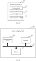
- FIG. 5 is a possible schematic structural diagram of the first network management unit in the foregoing embodiments.
- the first network management unit may exist in a product form of a chip.
- the network management unit 500 includes a processing module 502 and a communications module 503.
- the processing module 502 is configured to control and manage an action of the network management unit.
- the processing module 502 is configured to support the network management unit in performing processes 201, 202, and 203 in FIG. 2 , 2011 and 2013 in FIG. 3 , and 301 and 304 in FIG. 4 , and/or is used in another process of the technology described in this specification.
- the communications module 503 is configured to support communication between the first network management unit and another network entity, for example, communication between the first network management unit and the transport network manager.
- the first network management unit may further include a storage module 501, configured to store program code and data of the first network management unit.
- the processing module 502 may be a processor or a controller, for example, may be a central processing unit (Central Processing Unit, CPU), a general purpose processor, a digital signal processor (Digital Signal Processor, DSP), an application-specific integrated circuit (Application-Specific Integrated Circuit, ASIC), a field programmable gate array (Field Programmable Gate Array, FPGA) or another programmable logic device, a transistor logic device, a hardware component, or any combination thereof.
- the processing module 502 may implement or execute various examples of logical blocks, modules, and circuits described with reference to content disclosed in this application.
- the processor may be a combination for implementing a computing function, for example, a combination of one or more microprocessors, or a combination of the DSP and a microprocessor.
- the communications module 503 may be a communications interface, a transceiver, a transceiver circuit, or the like.
- the communications interface is a collective term and may include one or more interfaces.
- the storage module 501 may be a memory.
- the first network management unit in this embodiment of this application may be a first network management unit shown in FIG. 6 .
- the first network management unit 600 includes a processor 602, a communications interface 603, and a memory 601.
- the first network management unit 600 may further include a bus 604.
- the communications interface 603, the processor 602, and the memory 601 may be interconnected by using the bus 604.
- the bus 604 may be a peripheral component interconnect (Peripheral Component Interconnect, PCI for short) bus, an extended industry standard architecture (Extended Industry Standard Architecture, EISA for short) bus, or the like.
- the bus 604 may be categorized as an address bus, a data bus, a control bus, and the like. For ease of representation, only one thick line is used to represent the bus in FIG. 6 , but this does not mean that there is only one bus or only one type of bus.
- FIG. 7 is a possible schematic structural diagram of the transport network manager in the foregoing embodiments.
- the transport network manager may exist in a product form of a chip.
- the transport network manager 700 includes a processing module 702 and a communications module 703.
- the processing module 702 is configured to control and manage an action of the transport network manager.
- the processing module 702 is configured to support the transport network manager in performing 203 in FIG. 2 and processes 301, 302, 303, and 304 in FIG. 4 , and/or is used in another process of the technology described in this specification.
- the communications module 703 is configured to support communication between the transport network manager and another network entity, for example, communication between the transport network manager and the first network management unit.
- the transport network manager may further include a storage module 701, configured to store program code and data of the transport network manager.
- the processing module 702 may be a processor or a controller, such as a central processing unit (Central Processing Unit, CPU), a general-purpose processor, a digital signal processor (Digital Signal Processor, DSP), an application-specific integrated circuit (Application-Specific Integrated Circuit, ASIC), a field programmable gate array (Field Programmable Gate Array, FPGA), or another programmable logic device, a transistor logic device, a hardware component, or any combination thereof.
- the processing module 702 may implement or execute various examples of logical blocks, modules, and circuits described with reference to content disclosed in this application.
- the processor may be a combination for implementing a computing function, for example, a combination of one or more microprocessors, or a combination of the DSP and a microprocessor.
- the communications module 703 may be a communications interface, a transceiver, a transceiver circuit, or the like.
- the communications interface is a collective term and may include one or more interfaces.
- the storage module 701 may be a memory.
- the transport network manager in this embodiment of this application may be a transport network manager shown in FIG. 8 .
- the transport network manager 800 includes a processor 802, a communications interface 803, and a memory 801.
- the transport network manager 800 may further include a bus 804.
- the communications interface 803, the processor 802, and the memory 801 may be interconnected by using the bus 804.
- the bus 804 may be a peripheral component interconnect (Peripheral Component Interconnect, PCI for short) bus, an extended industry standard architecture (Extended Industry Standard Architecture, EISA for short) bus, or the like.
- the bus 804 may be categorized as an address bus, a data bus, a control bus, and the like. For ease of representation, the bus is represented by using only one thick line in FIG. 8 . However, it does not mean that there is only one bus or only one type of bus.
- the method or algorithm steps described with reference to the content disclosed in this application may be implemented by hardware, or may be implemented by the processor by executing a software instruction.
- the software instruction may include a corresponding software module.
- the software module may be stored in a random access memory (Random Access Memory, RAM), a flash memory, a read-only memory (Read Only Memory, ROM), an erasable programmable read-only memory (Erasable Programmable ROM, EPROM), an electrically erasable programmable read-only memory (Electrically EPROM, EEPROM), a register, a hard disk, a removable hard disk, a compact disc read-only memory (CD-ROM), or any other form of storage medium well-known in the art.
- RAM Random Access Memory
- ROM read-only memory
- EPROM erasable programmable read-only memory
- Electrically erasable programmable read-only memory Electrically erasable programmable read-only memory
- CD-ROM compact disc read-only memory
- a storage medium is coupled to the processor, so that the processor can read information from the storage medium, and write information into the storage medium.
- the storage medium may alternatively be a component of the processor.
- the processor and the storage medium may be located in an ASIC.
- the ASIC may be located in a core network interface device.
- the processor and the storage medium may exist in the core network interface device as discrete components.
- the functions described in this application may be implemented by hardware, software, firmware, or any combination thereof.
- the functions When the functions are implemented by software, the functions may be stored in a computer-readable medium or transmitted as one or more instructions or code in a computer-readable medium.
- the computer-readable medium includes a computer storage medium and a communications medium, where the communications medium includes any medium that facilitates transmission of a computer program from one place to another.
- the storage medium may be any available medium accessible to a general-purpose or dedicated computer.
Abstract
Description
- Embodiments of this application relate to the communications field, and in particular, to a network slice deployment method and an apparatus.
- Facing the future, mobile communications technologies and industries are about to enter a development phase of 5th-generation mobile communications (5th-Generation, 5G). 5G meets people's requirements for ultra-high traffic density, ultra-high connection density, ultra-high mobility, and the like, and provides users with extreme service experience such as high-definition videos, virtual reality, augmented reality, and cloud desktops. 5G penetrates into fields such as the internet of things and is deeply integrated with industrial facilities, medical instruments, and means of communications, to effectively meet informatization service requirements of vertical industries, such as industrial, medical, and transportation industries.
- A conventional network cellular network uses a "one-size-fits-all" network architecture, which has a dedicated support and information technology (Information Technology, IT) system and is suitable for a single-service type network. However, by using this vertical architecture, an operator has difficulty in extending a telecommunication network, and also has great difficulty in performing adjustment based on continuously changing user requirements, and meeting a requirement of a new-type use case. Therefore, in a 5G era, a conventional cellular network and a "one-size-fits-all" method need to be adjusted to support thousands of use cases, a plurality of user types, and use of various applications.
- In a future 5G system, network resources are sliced, a single physical network may be divided into a plurality of logical virtual networks, and an independent network slice is allocated to a typical service scenario. In the slice, for a service requirement, an enhanced network architecture is involved, to optimize and implement resource configuration, so that a plurality of network slices may share a network infrastructure, thereby improving network resource utilization.
- Embodiments of this application provide a method and an apparatus for creating a transport network, to resolve a problem in the prior art of low efficiency in establishing a transport network only by manually determining and inputting a related parameter, and a requirement for fast establishment of a network slice cannot be met.
- According to a first aspect, an embodiment of this application provides a network slice deployment method. The method includes:
obtaining, by a first network management unit, node instance information; determining, by the first network management unit, transmission requirement information corresponding to the node instance information; and sending, by the first network management unit, a transmission request message to a transport network manager, where the node instance information includes identifier information of a node instance or a network address of a node instance, and the transmission request message carries the transmission requirement information and the node instance information. The first management unit may be a network management unit NM, and the NM includes one or both of an end-to-end network management function and an end-to-end network orchestration function. The NM may be a cross-domain management unit, a cross-domain network slice management unit, a network slice management function unit, or the like. The node instance information is used to describe a node instance or describe an access manner of a node instance. - An embodiment of this application provides a new network slice deployment method. A transport network can be automatically created, to improve network slice deployment efficiency.
- With reference to the first aspect, in a possible implementation of the first aspect, the first network management unit sends node requirement information to a second network management unit, where the node requirement information includes an identifier of the node requirement information. The node requirement information is used to describe a requirement for deploying a node, for example, a specification, and a quantity of virtual machines that are needed. The node requirement information may include one or more of the following information: deployment template information of a node, a deployment specification of the node, a constraint requirement on a deployment location of the node, affinity and anti-affinity of the node, a latency requirement of the node, and the like.
- With reference to the first aspect or the first possible implementation of the first aspect, in a second possible implementation of the first aspect, the first network management unit obtains node instance description information corresponding to the node instance information. The node instance description information includes one or more of the following: the identifier of the node requirement information, a node type, an identifier of a node template, location information of a node, and specification information of the node.
- With reference to the first aspect or the first or the second possible implementation of the first aspect, in a third possible implementation of the first aspect, the first network management unit determines the transmission requirement information based on the node instance description information corresponding to the node instance information. The transmission requirement information may include one or more of the following: a transmission deployment specification, a latency, bandwidth, location constraint information, affinity and anti-affinity rules, quality of service QoS, bearer information, a network type, a reliability requirement, a mobility requirement, isolation requirement information, and the like.
- Optionally, the first network management unit may further determine a transmission template based on the node instance information, to determine the transmission requirement information, where the transmission template includes the transmission requirement information.
- Optionally, the first network management unit may further determine the transmission requirement information based on the node instance information and a preset policy. The preset policy may be a correspondence between the node description information and the transmission requirement information.
- According to a second aspect, an embodiment of this application provides a network slice deployment method. The method includes:
obtaining, by a transport network manager, node instance information, where the node instance information includes an identifier of a node instance or a network address of a node instance; determining, by the transport network manager, transmission requirement information corresponding to the node instance information; and configuring, by the transport network manager, a transmission resource corresponding to the transmission requirement information. - In this embodiment of this application, the transport network manager determines the transmission requirement information, to configure the transmission resource, thereby implementing network element function centralization, improving network creation efficiency, and satisfying rapid service launching.
- With reference to the second aspect, in a first possible implementation of the second aspect, the transport network manager obtains node instance description information corresponding to the node instance information. The node instance description information includes one or more of the following: an identifier of node requirement information, an identifier of a node template, a node type, location information of a node instance, and specification information of the node instance.
- The transport network manager may determine the transmission requirement information corresponding to the node instance information in the following several manners:
- 1. The transport network manager determines the transmission requirement information based on the node instance description information corresponding to the node instance information.
- 2. The transport network manager determines a transmission template based on the node instance information, to determine the transmission requirement information, where the transmission template includes the transmission requirement information.
- With reference to the second aspect or the first possible implementation of the second aspect, in a second possible implementation of the second aspect, before the determining, by the transport network manager, a transmission requirement, the transport network manager first receives a transmission management request, where the transmission management request carries the transmission template or transmission template indication information, and the transmission template indication information is used to obtain the transmission template.
- With reference to the second aspect, or the first or the second possible implementation of the second aspect, in a third possible implementation of the second aspect, before the obtaining, by a transport network manager, node instance information, the transport network manager sends a query request to a second network management unit, where the query request carries the node requirement information or slice information. The second network management unit may be a domain management unit DM.
- According to another aspect, an embodiment of this application provides a network management unit. As a network slice management apparatus, the network management unit may implement functions performed by the first network management unit in the foregoing method examples. The functions may be implemented by hardware, may be implemented by executing corresponding software by hardware, or may be implemented by using a chip. The hardware or the software includes one or more modules corresponding to the foregoing functions.
- In a possible implementation, a structure of the network management unit includes a processor and a communications interface. The processor is configured to support the first network management unit in performing the corresponding functions in the foregoing method. The communications interface is configured to support communication between the first management unit and another network element. The network management unit may further include a memory. The memory is configured to couple to the processor. The memory stores a program instruction and data that are necessary for the network management unit.
- According to another aspect, an embodiment of this application provides a transport network manager. As another network slice management apparatus, the transport network manager may implement functions performed by the transport network manager in the foregoing method embodiments. The functions may be implemented by hardware, may be implemented by executing corresponding software by hardware, or may be implemented by using a chip. The hardware or the software includes one or more modules corresponding to the foregoing functions.
- In a possible implementation, a structure of the transport network manager includes a processor and a communications interface. The processor is configured to support the transport network manager in performing the corresponding functions in the foregoing method. The communications interface is configured to support communication between the transport network manager and another network element. The transport network manager may further include a memory. The memory is configured to couple to the processor. The memory stores a program instruction and data that are necessary for the transport network manager.
- According to another aspect, an embodiment of this application provides a communications system. The system includes the network management unit and the transport network manager in the foregoing aspects.
- According to still another aspect, an embodiment of this application provides a computer storage medium. The computer storage medium is configured to store a computer software instruction used by the foregoing network management unit, and includes a program designed for performing the foregoing aspects.
- According to still another aspect, an embodiment of this application provides a computer storage medium. The computer storage medium is configured to store a computer software instruction used by the foregoing transport network manager, and includes a program designed for performing the foregoing aspects.
- Compared with the prior art, the embodiments of this application provide a new network slice deployment method. A transport network can be automatically created, to improve network slice deployment efficiency.
-
-
FIG. 1 is a simplified schematic diagram of a network architecture according to an embodiment of this application; -
FIG. 2 is a flowchart of a network slice deployment method according to an embodiment of this application; -
FIG. 3 is a flowchart of another network slice deployment method according to an embodiment of this application; -
FIG. 4 is a flowchart of another network slice deployment method according to an embodiment of this application; -
FIG. 5 is a schematic structural diagram of a management unit according to an embodiment of this application; -
FIG. 6 is a schematic structural diagram of another management unit according to an embodiment of this application; -
FIG. 7 is a schematic structural diagram of a transport network manager according to an embodiment of this application; and -
FIG. 8 is a schematic structural diagram of another transport network manager according to an embodiment of this application. - Before technical solutions are described, to facilitate understanding of the technical solutions in the embodiments of this application, some terms in the embodiments of this application are first explained and described.
- A network slice may also be referred to as a network slice instance, and is a combination of network function units (network function, NF) and resources that ensures that a carried service can meet a requirement of a service level agreement (service level agreement, SLA). Hard isolation (for example, physical isolation) or soft isolation (for example, logical isolation) may be performed on these NFs and resources based on different requirements, and each network slice is logically independent. The network slice may include at least a core network (core network, CN) part, an access network (access network, AN) part, and a transport network (transport network, TN) part, or may include any two or one of a CN part, an AN part, and a TN part. A network slice is a set including a group of network functions, resources for running these network functions, and particular configurations of these network functions. These network functions and corresponding configurations form a complete logical network. The logical network includes a network feature required for meeting a particular service, and a corresponding network service is provided for this particular service scenario.
- The network slice is a broad concept, and may be a conventional network or a dedicated network. A network slice subnet is also a network slice.
- A network slice subnet may be referred to as a network slice subnet instance, and is a combination of network functions and resources. Usually, the network slice subnet may be obtained by splitting a network slice, or a network slice may be directly used as the network slice subnet.
- A concept such as the network slice or the network slice subnet mentioned in this specification may be considered to be equivalent to a network slice instance or a network slice subnet instance.
- A tenant refers to one or more network service users sharing a group of physical and virtual resources. The tenant may be a renter of an operator network. For example, an electric power company rents the operator network to deploy a smart metering service, and the electric power company is a tenant of an operator.
-
FIG. 1 is a network architecture to which an embodiment of this application is applied. A transport network management method provided in this embodiment of this application may be implemented by function units in the network architecture shown inFIG. 1 , and the network architecture may be deployed in a 5G system. The following describes each function unit in the network architecture shown inFIG. 1 in detail. - As shown in
FIG. 1 , the network architecture may include a service management unit (service management, SM), a network management unit (network management, NM), a domain management unit (domain management, DM), a transport network manager (transport network manager, TNM), and the like. - The SM is a service management unit, and is mainly configured to: receive a service requirement of a related tenant, convert the service requirement into a requirement related to a network slice, and perform service management. The SM may be deployed in an operation support system (operation support system, OSS), or may be deployed outside an OSS. The SM may be a management unit or an operation unit of the tenant. The SM may be independently deployed, or may be integrated into a management unit (for example, a business support system (business support system, BSS), a service management unit, a service orchestration unit, or a service management and orchestration unit). It should be noted that the SM is not limited to the name shown in
FIG. 1 , and the SM may alternatively be named as a customer service management unit (customer service management function) or a communication service management unit (communication service management function, CSMF). - The NM includes one or both of an end-to-end network management function and an end-to-end network orchestration function, and may have some or all of the following functions: end-to-end network management (for example, network lifecycle management, network template management, network fault management, network performance management, and network configuration management), mapping between an end-to-end network function, a subnet function, and a network function, coordination of network resources or sub-SLAs provided in different domains (for example, an access network domain, a core network domain, and a transmission domain), decomposition of network requirement information into subnet requirement information, and uniform orchestration of subnet functions and network functions provided in subdomains, so that subnets or network functions provided in different subdomains can meet a target service or network requirement (for example, a requirement of an SLA, a requirement of a key performance indicator (key performance indicator, KPI), and a requirement of quality of service (quality of service, QoS)). The NM may be deployed in an OSS, or may be deployed outside an OSS. The NM may be independently deployed, or may be integrated into a management unit (for example, a network orchestration unit, a network management and orchestration unit, a service management unit, a service orchestration unit, a service management and orchestration unit, or a network function virtualization orchestrator (network function virtualization orchestrator, NFVO)). It should be noted that the NM is not limited to the name shown in
FIG. 1 , and the NM may alternatively be named as a cross-domain management unit, a cross-domain network slice management unit, a network slice management function unit (network slice management function, NSMF), or the like. - The DM includes one or both of a subnet management function and an orchestration function, and may have some or all of the following functions: domain management, which, for example, may include subnet lifecycle management (creation, update, and deletion), subnet fault management, subnet performance management, and subnet configuration management; service management (including service lifecycle management, service fault management, service performance management, service configuration management, and the like); and network resources, for example, coordination of NFs and network element (network element, NE), for uniform orchestration. The DM may be deployed in an OSS, or may be deployed outside an OSS. The DM may be independently deployed, or may be integrated into a management unit (for example, a network management unit, a network orchestration unit, a network management and orchestration unit, a network element management unit, a network function management unit, a service management unit, a service orchestration unit, a domain management unit, a service management and orchestration unit, or an NFVO). It should be noted that the DM is not limited to the name shown in
FIG. 1 , and the DM may alternatively be named as a domain slice management unit, a network slice subnet management unit (network slice Subnet management function, NSSMF), or the like. - Specifically, a subnet managed by the DM may include one or more of the following parts: an AN part, a CN part, and a TN part. When the subnet managed by the DM includes only the AN part, it may be considered that the subnet management unit is an AN DM. When the subnet managed by the DM includes only the CN part, it may be considered that the subnet management unit is a CN DM. When the subnet managed by the DM includes the AN part and the CN part, it may be considered that the subnet management unit is a Mix DM.
- The TNM includes one or both of a transport network management function and a transport network orchestration function, and may have some or all of the following functions: management of a transport network part, which, for example, may include lifecycle management (creation, update, and deletion) of the transport network part, fault management of the transport network part, performance management of the transport network part, configuration management of the transport network part, and the like. The TNM may be deployed in an OSS, or may be deployed outside an OSS. The TNM may be independently deployed, or may be integrated into a management unit (for example, a network management unit, a network orchestration unit, a network management and orchestration unit, a domain management unit, a network element management unit, a service management unit, a service orchestration unit, a domain management unit, a service management and orchestration unit, or an NFVO). It should be noted that the TNM is not limited to the name shown in
FIG. 1 , and the TNM may alternatively be named as a (transport network) subnet management unit, a network slice transport network management unit, or the like. The transport network may refer to a link. -
FIG. 1 is merely an example of an architecture diagram. In addition to the function nodes shown inFIG. 1 , the network architecture may further include another function node. This is not limited in this embodiment of this application. -
FIG. 2 shows a network slice deployment method according to an embodiment of this application. The method may be applied to the network architecture shown inFIG. 1 , and a specific method is as follows:
S201. A first network management unit obtains node instance information, where the node instance information includes identifier information of a node instance or a network address of a node instance. The node instance is a specific network function instance or network element device. In this application, concepts of the node instance and a node are the same. In this application, the word "node instance" is used for description. The network address of the node instance may include an IP address of the node instance, a Mac address of the node instance, or the like. - Optionally, the first network management unit may obtain a plurality of pieces of node instance information.
- The first network management unit may be the NM shown in
FIG. 1 . In this embodiment of this application, an NSMF is used as an example for specific description. - A manner in which the NSMF obtains the node instance information is shown in
FIG. 3 , and may specifically include the following implementation steps. - S2011. The NSMF sends a network slice subnet management request to a second network management unit, where the network slice subnet management request carries network slice subnet requirement information. The second network management unit may be a DM. In this embodiment of this application, specifically, an NSSMF is used as an example for description.
- Specifically, the network slice subnet requirement information may include one or more of the following information:
a type of a network slice or a network slice subnet, a quantity of users that need to be carried by the network slice subnet, distribution of the users that need to be carried by the network slice subnet, a coverage level of the network slice subnet, a latency of the network slice subnet, bandwidth of the network slice subnet, requirement information of a deployment location of the network slice subnet, a network slice subnet template corresponding to the network slice subnet, identifier information of the network slice subnet template corresponding to the network slice subnet, and deployment specification information of the network slice subnet template corresponding to the network slice subnet. - It may be understood that the network slice subnet management request is a named request message name, and is used to request the DM to manage the network slice subnet. A message name is not limited herein. The network slice subnet management request may further include any one of the following: a network slice subnet creation request, a network slice subnet instantiation request, a network slice subnet modification request, a network slice subnet capacity expansion request, a network slice subnet configuration request, and the like.
- For example, when an internet of vehicles enterprise rents a network of an operator to implement a self-driving service, the internet of vehicles enterprise signs a related agreement with the operator; and a network management system of the operator sends a network slice subnet creation request to an NSSMF, and the network slice subnet creation request is used to request the NSSMF to create or allocate a corresponding network slice subnet instance to form a network slice instance to support the self-driving service of the internet of vehicles enterprise.
- S2012. The NSSMF deploys a corresponding network slice subnet instance based on the network slice subnet requirement information.
- The deploying a corresponding network slice subnet instance based on the network slice subnet requirement information may specifically include: creating a corresponding network slice subnet instance based on the network slice subnet requirement information, or instantiating a corresponding network slice subnet instance based on the network slice subnet requirement information.
- One network slice subnet instance may include one or more node instances. Therefore, deploying one network slice subnet instance includes deploying one or more node instances.
- Deploying a node instance may include creating the node instance, configuring the node instance, or instantiating the node instance.
- Specifically, deploying the node instance includes allocating or selecting a resource required by the node instance, and configuring the node instance. The resource may include a computing resource, a storage resource, a network resource, and the like.
- The node instance is a network function or a network element device, and includes but is not limited to one or more of the following:
- an authentication server function (authentication server function, AUSF);
- an access management function (access and mobility management function, AMF);
- a data network (data network, DN), for example, operator services and Internet access or 3rd party services;
- a structured data storage network function (structured data storage network function, SDSF);
- an unstructured data storage network function (unstructured data storage network function, UDSF);
- a network exposure function (network exposure function, NEF);
- a network repository function (network repository function, NRF), which may also be represented as a network function repository function;
- a policy control function (policy control function, PCF);
- a session management function (session management function, SMF);
- unified data management (unified data management, UDM);
- a user plane function (user plane function, UPF);
- an application function (application function, AF);
- a next generation NodeB (generation nodeB, gNB) or a 5G base station;
- an evolved NodeB function (evolved node B, eNB);
- an evolved LTE evolved NodeB (evolved LTE evolved node B, eLTE eNB);
- a NodeB (node B, NB);
- a next generation NodeB central unit (gNB Central Unit);
- a next generation NodeB distributed unit (gNB Distribute Unit); and
- a mobility management entity (Mobile Management Entity, MME).
- The node instance may also refer to a connection point of any one of the foregoing network functions, and one of the network functions may include one or more connection points.
- In step S2012, the NSSMF deploys the corresponding network slice subnet instance based on the network slice subnet requirement information. The following uses several feasible implementations as examples.
- Manner 1: The NSSMF decomposes the network slice subnet requirement information into node requirement information, and deploys a corresponding node instance based on the node requirement information to obtain node instance information. Optionally, after decomposing the network slice subnet requirement information into the node requirement information, the NSSMF sends the node requirement information to a node instance management unit, and the node instance management unit deploys the corresponding node instance.
- The node requirement information is used to describe a requirement for deploying a node, for example, a specification, and a quantity of virtual machines that are needed. The node requirement information may include one or more of the following information:
deployment template information of a node, a deployment specification of the node, a constraint requirement on a deployment location of the node, affinity and anti-affinity of the node, a latency requirement of the node, and the like. - The following uses the latency requirement of the node as an example to describe in detail how the NSSMF decomposes the network slice subnet requirement information into the node requirement information. For example, a latency of a network slice subnet is 10 ms, and the network slice subnet includes a node 1 and a node 2. A local preset policy or algorithm indicates that a latency ratio of the node 1 to the node 2 is 2:3. In this case, a latency requirement of a node is decomposed into that a latency of the node 1 is 4 ms, and a latency of the node 2 is 6 ms.
- For another example, when the network slice subnet requirement information is a quantity of users, the NSSMF determines, based on the quantity of users, whether a node deployment specification is large or small.
- The node instance information is used to identify the node instance or describe an access manner of the node instance. Specifically, the deploying a corresponding node instance based on the node requirement information, to generate node instance information includes:
allocating, by the NSSMF, a node instance identifier for uniquely identifying the node instance, or allocating and configuring, by the NSSMF, the network address of the node instance. - Manner 2: The NSSMF decomposes the network slice subnet requirement information into the node requirement information. A specific decomposition process is the same as that in the foregoing manner.
- A node template is obtained based on the node requirement information, and the corresponding node instance is deployed based on the node template, to generate the node instance information. The node instance information is used to describe the node instance. The node template is used to describe deployment information of the node instance. The node template includes one or more of the following information: a type of the node, a version of the node, provider information of the node, virtual resource information needed by the node, and the like. It should be noted that a template may also be referred to as a descriptor, a blueprint, or the like, and same concepts are described in this application. The node template may include any one of the following: a network function template, a virtual network function template, a network element template, and a connection point template.
- For a specific manner of deploying the corresponding node instance, to generate the node instance information, refer to the foregoing implementation.
- Manner 3: The NSSMF obtains a corresponding network slice subnet template based on the network slice subnet requirement information. Specifically, the network slice subnet requirement information carries identifier information of the network slice subnet template, and the identifier information of the network slice subnet template is used to obtain the network slice subnet template.
- The network slice subnet template includes node requirement information required for forming the network slice subnet, and the node instance is deployed based on the node requirement information, to generate the node instance information. The node instance information is used to describe the node instance.
- For a specific manner of deploying the corresponding node instance, to generate the node instance information, refer to the foregoing implementation.
- Manner 4: The NSSMF obtains a corresponding network slice subnet template based on the network slice subnet requirement information. The network slice subnet template includes node template information required for forming the network slice subnet. The node template is obtained based on the node template information, and the node instance is deployed based on the node template, to generate the node instance information. The node instance information is used to describe the node instance.
- The node template information includes one or more of the following: an identifier of a node template, a deployment level of the node template, and a name of the node template.
- For a specific manner of deploying the corresponding node instance, to generate the node instance information, refer to the foregoing implementation.
- Optionally, the NSSMF further determines node instance description information corresponding to the node instance information, and sends the node instance description information to the NSMF based on a requirement.
- The node instance description information is specifically used to describe the node instance. The node instance description information may include one or more of the following: an identifier of node requirement information, an identifier of a node template, a node type, location information of a node, and specification information of the node.
- Specifically, when the node instance description information is the identifier of the node requirement information, the NSSMF deploys the node instance based on the node requirement information. The identifier of the node requirement information is used to uniquely identify the node requirement information. Therefore, the identifier of the node requirement information corresponding to the node instance information may be directly determined.
- When the node instance description information is the identifier of the node template, the NSSMF deploys the node instance based on the node template. The identifier of the node template is used to uniquely identify the node template. Therefore, the identifier of the node template corresponding to the node instance information may be directly determined.
- When the node instance description information is the identifier of the node template, the node requirement information or the node template includes the node type. Therefore, the node type corresponding to the node instance information may be directly determined.
- When the node instance description information is the location information of the node, the NSSMF deploys the node instance at a corresponding location (for example, an area or a DC). Therefore, the node location information corresponding to the node instance information may be directly determined.
- When the node instance description information is the location information of the node, when a deployed node instance is of a specification, the NSSMF may directly determine a specification of the node corresponding to the node instance information.
- The node type information is used to distinguish different types of nodes, and a node type may be any one of the following:
an authentication server function (authentication server function, AUSF); an access management function (access and mobility management function, AMF); a data network (data network, DN), for example, operator services and Internet access or 3rd party services; a structured data storage network function (structured data storage network function, SDSF); an unstructured data storage network function (unstructured data storage network function, UDSF); a network exposure function (network exposure function, NEF); a network repository function (network repository function, NRF), which may also be represented as a network function repository function; a policy control function (policy control function, PCF); a session management function (session management function, SMF); unified data management (unified data management, UDM); a user plane function (user plane function, UPF); an application function (application function, AF); a next generation NodeB function (generation nodeB function, gNBF) or a 5G base station function; an evolved NodeB function (evolved node B function, eNBF); an evolved LTE evolved NodeB function (evolved LTE evolved node B function, eLTE eNB); and a NodeB function (node B function, NBF). - The identifier of the node template is used to identify the node template, and the node template includes one or more of the following information: a type of the node, a version of the node, provider information of the node, virtual resource information needed by the node, and the like.
- The identifier of the node requirement information is used to represent requirement information of a node. The node requirement information includes one or more of the following information: a template of the node, a deployment specification of the node, affinity and anti-affinity requirements of the node, and the like.
- The location information of the node is used to represent a deployment location of a node.
- The deployment specification information of the node is used to describe capacity information or a deployment level (e.g. Flavor Id or Instantiation level) of a node.
- S2013. The NSSMF sends node instance information to the NSMF.
- Optionally, the NSSMF sends a plurality of pieces of node instance information to the NSMF.
- After completing deployment of the corresponding network slice subnet, the NSSMF returns a network slice subnet management request completion message to the NSMF. The request completion message carries the node instance information.
- Optionally, after completing deployment of the corresponding network slice subnet, the NSSMF sends a notification message to the NSMF. The notification message carries the node instance information.
- Before S2011, to be specific, before the NSMF sends the network slice subnet management request to the second network management unit, the NSMF may further receive a network slice management request. Similarly, a network slice creation request is a named request message name, and is used to request the NM to manage the network slice. A message name is not limited herein. The network slice creation request may be a network slice management request, a network slice instantiation request, a network slice modification request, a network slice capacity expansion request, a network slice configuration request, or the like.
- The network slice creation request carries network slice requirement information. The network slice requirement information is used to determine information required for creating the network slice, and may specifically include, but is not limited to, one or more of the following information: bandwidth, a latency, coverage, a success rate, a location, a traffic model, a quantity of users, and user distribution.
- S202. The first network management unit determines transmission requirement information corresponding to the node instance information.
- Specifically, the first network management unit may determine node instance description information based on the node instance information, and determine, based on the node instance description information, the transmission requirement information corresponding to the node instance information.
- Optionally, the first network management unit may further determine the node instance description information based on the node instance information, and determine a corresponding transmission descriptor based on the node instance description information, where the transmission descriptor includes the transmission requirement information and the corresponding node instance description information, so that the first network management unit determines the transmission requirement information corresponding to the node instance information.
- The transmission descriptor herein may be a link descriptor or a virtual link descriptor. The word "descriptor" herein is not limited, and may be a template, a blueprint, or the like.
- For example, the transmission descriptor includes the following information: a node type 1, a latency 5 ms, and that the node instance description information corresponding to the node instance information is the node type 1, and then, the transmission requirement information corresponding to the node instance information may be determined, that is, the latency is 5 ms.
- For another example, the transmission descriptor includes the following information: a node type 1, a node type 2, a latency 5 ms, and that node instance description information corresponding to node instance information 1 is the node type 1, node instance description information corresponding to node instance information 2 is the node type 2, and it may be determined that a latency required for transmission between the node instance information 1 and the node instance information 2 is 5 ms.
- Compared with S202, the first network management unit may further determine, based on the node instance information and a preset policy, the transmission requirement information corresponding to the node instance. The preset policy may be a correspondence between the node description information and the transmission requirement information. For example, a latency between the node type 1 and the node type 2 is 5 ms.
- The following uses a specific example to describe a case in which the NSMF decomposes the network slice requirement information into network slice subnet requirement information, and determines the transmission requirement information.
- In an example, the subnet requirement information and the transmission requirement information may be determined based on a preset policy.
- For example, according to the decomposition algorithm, a ratio of a latency of a core network subnet: a latency of an access network subnet: a transmission latency is 1: 2: 3. When the requirement information of the network slice carries a latency of 6 ms, it may be determined, based on the decomposition algorithm, that the latency of the core network subnet is 1 ms, the latency of the access network subnet is 2 ms, and the transmission latency is 3 ms.
- The transmission requirement information may include, but is not limited to, one or more of the following: a latency, bandwidth, location constraint information, QoS, bearer information, a network type, reliability information, mobility, and isolation requirement information. The location constraint information may include affinity or anti-affinity, a data center DC, a region region, and the like. S203. The first network management unit sends a transmission request message to a transport network manager, where the transmission request message carries the transmission requirement information and the node instance information.
- The transmission request message is used to request a transmission resource of the node instance corresponding to the node instance information.
- The node instance information is obtained by using the NSMF, and the transmission requirement information is automatically determined based on the node instance information, so that transmission corresponding to the node instance is automatically deployed. In the network slice deployment method provided in this embodiment of this application, a transport network can be automatically created, to improve network slice deployment efficiency.
-
FIG. 3 shows another network slice deployment method according to an embodiment of this application. The method may be applied to the network architecture shown inFIG. 1 . A main difference between this embodiment and the foregoing embodiment is that a transport network manager may determine transmission requirement information to configure a transmission resource. A specific method is as follows. - 5301. A transport network manager obtains node instance information, where the node instance information includes identifier information of a node instance or a network address of a node instance.
- S302. The transport network manager determines transmission requirement information corresponding to the node instance information.
- For a manner in which the transport network manager determines a transmission requirement, refer to a specific implementation in the foregoing embodiment.
- S303. The transport network manager configures a transmission resource corresponding to the transmission requirement information.
- For a manner in which the transport network manager determines a transmission requirement, refer to a specific implementation in the foregoing embodiment.
- In this embodiment of this application, the transport network manager determines the transmission requirement information, to configure the transmission resource, thereby implementing network element function centralization, improving network creation efficiency, and satisfying rapid service launching.
- Before S301, to be specific, before the transport network manager obtains the node instance information, the transport network manager sends a query request to a second network management unit, where the query request carries node requirement information or slice information.
- The second network management unit may be a DM, and specifically, may be an NSSMF.
- Before S301, to be specific, before the transport network manager obtains the node instance information, the transport network manager receives a transmission management request sent by a network management unit, where the transmission management request carries at least one piece of transmission requirement information. In S302, the transport network manager determines corresponding transmission requirement information in the at least one piece of transmission requirement information based on the node instance information.
- Specifically, the transport network manager may determine node instance description information based on the node instance information, and determine, based on the node instance description information, the transmission requirement information corresponding to the node instance information.
- Before S301, to be specific, before the transport network manager obtains the node instance information, the transport network manager receives a transmission management request sent by a network management unit, where the transmission management request carries at least one transmission descriptor or at least one piece of transmission descriptor indication information. The transmission descriptor indication information is used to obtain the transmission descriptor. The transmission descriptor includes the transmission requirement information. Optionally, the transmission descriptor includes the node requirement information or node template information.
- The transport network manager may also determine the node instance description information based on the node instance information, and determine a corresponding transmission descriptor in the at least one transmission descriptor based on the node instance description information, where the transmission descriptor includes the transmission requirement information and the corresponding node instance description information, so that the transport network manager determines the transmission requirement information corresponding to the node instance information.
- The foregoing describes the solutions in the embodiments of this application mainly from a perspective of interaction between network elements. It may be understood that to implement the foregoing functions, the network elements, for example, the first management unit and the second management unit, include a corresponding hardware structure and/or a corresponding software module for performing the functions. A person skilled in the art should easily be aware that, units and algorithm steps in the examples described with reference to the embodiments disclosed in this specification may be implemented in a form of hardware or in a form of a combination of hardware and computer software in this application. Whether a function is performed by hardware or hardware driven by computer software depends on particular applications and design constraints of the technical solutions. A person skilled in the art may use a different method to implement the described functions for each particular application, but it should not be considered that the implementation goes beyond the scope of this application.
- In the embodiments of this application, the first management unit, the second management unit, and the like may be divided into function modules based on the foregoing method examples. For example, the function modules may be obtained through division based on the corresponding functions, or two or more functions may be integrated into one processing module. The integrated module may be implemented in a form of hardware, or may be implemented in a form of a software function module. It should be noted that the module division in the embodiments of this application is an example, and is merely logical function division, and there may be other division manners in actual implementation.
- When integrated modules are used,
FIG. 5 is a possible schematic structural diagram of the first network management unit in the foregoing embodiments. The first network management unit may exist in a product form of a chip. Thenetwork management unit 500 includes aprocessing module 502 and acommunications module 503. Theprocessing module 502 is configured to control and manage an action of the network management unit. For example, theprocessing module 502 is configured to support the network management unit in performingprocesses FIG. 2 , 2011 and 2013 inFIG. 3 , and 301 and 304 inFIG. 4 , and/or is used in another process of the technology described in this specification. Thecommunications module 503 is configured to support communication between the first network management unit and another network entity, for example, communication between the first network management unit and the transport network manager. The first network management unit may further include astorage module 501, configured to store program code and data of the first network management unit. - The
processing module 502 may be a processor or a controller, for example, may be a central processing unit (Central Processing Unit, CPU), a general purpose processor, a digital signal processor (Digital Signal Processor, DSP), an application-specific integrated circuit (Application-Specific Integrated Circuit, ASIC), a field programmable gate array (Field Programmable Gate Array, FPGA) or another programmable logic device, a transistor logic device, a hardware component, or any combination thereof. Theprocessing module 502 may implement or execute various examples of logical blocks, modules, and circuits described with reference to content disclosed in this application. Alternatively, the processor may be a combination for implementing a computing function, for example, a combination of one or more microprocessors, or a combination of the DSP and a microprocessor. Thecommunications module 503 may be a communications interface, a transceiver, a transceiver circuit, or the like. The communications interface is a collective term and may include one or more interfaces. Thestorage module 501 may be a memory. - When the
processing module 502 is a processor, thecommunications module 503 is a communications interface, and thestorage module 501 is a memory, the first network management unit in this embodiment of this application may be a first network management unit shown inFIG. 6 . Referring toFIG. 6 , the firstnetwork management unit 600 includes aprocessor 602, acommunications interface 603, and amemory 601. Optionally, the firstnetwork management unit 600 may further include abus 604. Thecommunications interface 603, theprocessor 602, and thememory 601 may be interconnected by using thebus 604. Thebus 604 may be a peripheral component interconnect (Peripheral Component Interconnect, PCI for short) bus, an extended industry standard architecture (Extended Industry Standard Architecture, EISA for short) bus, or the like. Thebus 604 may be categorized as an address bus, a data bus, a control bus, and the like. For ease of representation, only one thick line is used to represent the bus inFIG. 6 , but this does not mean that there is only one bus or only one type of bus. - When integrated modules are used,
FIG. 7 is a possible schematic structural diagram of the transport network manager in the foregoing embodiments. The transport network manager may exist in a product form of a chip. Thetransport network manager 700 includes aprocessing module 702 and acommunications module 703. Theprocessing module 702 is configured to control and manage an action of the transport network manager. For example, theprocessing module 702 is configured to support the transport network manager in performing 203 inFIG. 2 and processes 301, 302, 303, and 304 inFIG. 4 , and/or is used in another process of the technology described in this specification. Thecommunications module 703 is configured to support communication between the transport network manager and another network entity, for example, communication between the transport network manager and the first network management unit. The transport network manager may further include astorage module 701, configured to store program code and data of the transport network manager. - The
processing module 702 may be a processor or a controller, such as a central processing unit (Central Processing Unit, CPU), a general-purpose processor, a digital signal processor (Digital Signal Processor, DSP), an application-specific integrated circuit (Application-Specific Integrated Circuit, ASIC), a field programmable gate array (Field Programmable Gate Array, FPGA), or another programmable logic device, a transistor logic device, a hardware component, or any combination thereof. Theprocessing module 702 may implement or execute various examples of logical blocks, modules, and circuits described with reference to content disclosed in this application. Alternatively, the processor may be a combination for implementing a computing function, for example, a combination of one or more microprocessors, or a combination of the DSP and a microprocessor. Thecommunications module 703 may be a communications interface, a transceiver, a transceiver circuit, or the like. The communications interface is a collective term and may include one or more interfaces. Thestorage module 701 may be a memory. - When the
processing module 702 is a processor, thecommunications module 703 is a communications interface, and thestorage module 701 is a memory, the transport network manager in this embodiment of this application may be a transport network manager shown inFIG. 8 . - Referring to
FIG. 8 , thetransport network manager 800 includes aprocessor 802, acommunications interface 803, and amemory 801. Optionally, thetransport network manager 800 may further include abus 804. Thecommunications interface 803, theprocessor 802, and thememory 801 may be interconnected by using thebus 804. Thebus 804 may be a peripheral component interconnect (Peripheral Component Interconnect, PCI for short) bus, an extended industry standard architecture (Extended Industry Standard Architecture, EISA for short) bus, or the like. Thebus 804 may be categorized as an address bus, a data bus, a control bus, and the like. For ease of representation, the bus is represented by using only one thick line inFIG. 8 . However, it does not mean that there is only one bus or only one type of bus. - The method or algorithm steps described with reference to the content disclosed in this application may be implemented by hardware, or may be implemented by the processor by executing a software instruction. The software instruction may include a corresponding software module. The software module may be stored in a random access memory (Random Access Memory, RAM), a flash memory, a read-only memory (Read Only Memory, ROM), an erasable programmable read-only memory (Erasable Programmable ROM, EPROM), an electrically erasable programmable read-only memory (Electrically EPROM, EEPROM), a register, a hard disk, a removable hard disk, a compact disc read-only memory (CD-ROM), or any other form of storage medium well-known in the art. For example, a storage medium is coupled to the processor, so that the processor can read information from the storage medium, and write information into the storage medium. Certainly, the storage medium may alternatively be a component of the processor. The processor and the storage medium may be located in an ASIC. In addition, the ASIC may be located in a core network interface device. Certainly, the processor and the storage medium may exist in the core network interface device as discrete components.
- A person skilled in the art should be aware that in the foregoing one or more examples, the functions described in this application may be implemented by hardware, software, firmware, or any combination thereof. When the functions are implemented by software, the functions may be stored in a computer-readable medium or transmitted as one or more instructions or code in a computer-readable medium. The computer-readable medium includes a computer storage medium and a communications medium, where the communications medium includes any medium that facilitates transmission of a computer program from one place to another. The storage medium may be any available medium accessible to a general-purpose or dedicated computer.
- The objectives, technical solutions, and beneficial effects of this application are further described in detail in the foregoing specific embodiments. It should be understood that the foregoing descriptions are merely specific embodiments of this application, but are not intended to limit the protection scope of this application. Any modification, equivalent replacement, improvement, or the like made based on the technical solutions of this application shall fall within the protection scope of this application.
Claims (28)
- A network slice deployment method, comprising:obtaining, by a first network management unit, node instance information, wherein the node instance information comprises identifier information of a node instance or a network address of a node instance;determining, by the first network management unit, transmission requirement information corresponding to the node instance information; andsending, by the first network management unit, a transmission request message to a transport network manager, wherein the transmission request message carries the transmission requirement information and the node instance information.
- The method according to claim 1, wherein the method further comprises:
sending, by the first network management unit, node requirement information to a second network management unit, wherein the node requirement information comprises an identifier of the node requirement information. - The method according to claim 1 or 2, wherein the method further comprises:
obtaining, by the first network management unit, node instance description information corresponding to the node instance information, wherein the node instance description information comprises one or more of the following: the identifier of the node requirement information, a node type, an identifier of a node template, location information of a node, and specification information of the node. - The method according to any one of claims 1 to 3, wherein the determining, by the first network management unit, transmission requirement information corresponding to the node instance information comprises: determining, by the first network management unit, the transmission requirement information based on the node instance description information corresponding to the node instance information.
- The method according to any one of claims 1 to 3, wherein the determining, by the first network management unit, transmission requirement information corresponding to the node instance information comprises: determining, by the first network management unit, a transmission template based on the node instance information, wherein the transmission template comprises the transmission requirement information.
- The method according to any one of claims 1 to 3, wherein the determining, by the first network management unit, requirement information corresponding to the node instance information comprises: determining, by the first network management unit, the transmission requirement information based on the node instance information and a preset policy.
- The method according to any one of claims 1 to 6, wherein the transmission requirement information comprises one or more of the following: a transmission deployment specification, a latency, bandwidth, location constraint information, affinity and anti-affinity rules, quality of service QoS, bearer information, a network type, a reliability requirement, a mobility requirement, and isolation requirement information.
- A network slice deployment method, comprising:obtaining, by a transport network manager, node instance information, wherein the node instance information comprises identifier information of a node instance or a network address of a node instance;determining, by the transport network manager, transmission requirement information corresponding to the node instance information; andconfiguring, by the transport network manager, a transmission resource corresponding to the transmission requirement information.
- The method according to claim 8, wherein the method further comprises:
obtaining, by the transport network manager, node instance description information corresponding to the node instance information, wherein the node instance description information comprises one or more of the following: an identifier of node requirement information, an identifier of a node template, a node type, location information of a node instance, and specification information of the node instance. - The method according to claim 8 or 9, wherein the determining, by the transport network manager, transmission requirement information corresponding to the node instance information comprises: determining, by the transport network manager, the transmission requirement information based on the node instance description information corresponding to the node instance information.
- The method according to claim 8 or 9, wherein the determining, by the transport network manager, transmission requirement information corresponding to the node instance information comprises: determining, by the transport network manager, a transmission template based on the node instance information, wherein the transmission template comprises the transmission requirement information.
- The method according to claim 11, before the determining, by the transport network manager, transmission requirement information corresponding to the node instance information, further comprising:
receiving, by the transport network manager, a transmission management request, wherein the transmission management request carries the transmission template or transmission template indication information, and the transmission template indication information is used to obtain the transmission template. - The method according to any one of claims 8 to 12, wherein before the obtaining, by a transport network manager, node instance information, the method comprises:
sending, by the transport network manager, a query request to a second network management unit, wherein the query request carries the node requirement information or slice information. - A network management unit, comprising:an obtaining unit, configured to obtain node instance information, wherein the node instance information comprises identifier information of a node instance or a network address of a node instance;a determining unit, configured to determine transmission requirement information corresponding to the node instance information; anda sending unit, configured to send a transmission request message to a transport network manager, wherein the transmission request message carries the transmission requirement information and the node instance information.
- The network management unit according to claim 14, wherein
the sending unit is further configured to send node requirement information to a second network management unit, wherein the node requirement information comprises an identifier of the node requirement information. - The network management unit according to claim 14 or 15, wherein
the obtaining unit is further configured to obtain node instance description information corresponding to the node instance information, wherein the node instance description information comprises one or more of the following: the identifier of the node requirement information, a node type, an identifier of a node template, location information of a node, and specification information of the node. - The network management unit according to any one of claims 14 to 16, wherein the determining, by the determining unit, transmission requirement information corresponding to the node instance information specifically comprises: determining, by the determining unit, the transmission requirement information based on the node instance description information corresponding to the node instance information.
- The network management unit according to any one of claims 14 to 16, wherein the determining, by the determining unit, transmission requirement information corresponding to the node instance information specifically comprises: determining, by the determining unit, a transmission template based on the node instance information, wherein the transmission template comprises the transmission requirement information.
- The network management unit according to any one of claims 14 to 16, wherein the determining, by the determining unit, requirement information corresponding to the node instance information specifically comprises: determining, by the determining unit, the transmission requirement information based on the node instance information and a preset policy.
- The network management unit according to any one of claims 14 to 19, wherein the transmission requirement information comprises one or more of the following: a transmission deployment specification, a latency, bandwidth, location constraint information, affinity and anti-affinity rules, quality of service QoS, bearer information, a network type, a reliability requirement, a mobility requirement, and isolation requirement information.
- A management unit, comprising:an obtaining unit, configured to obtain node instance information, wherein the node instance information comprises identifier information of a node instance or a network address of a node instance; anda processing unit, configured to determine transmission requirement information corresponding to the node instance information, whereinthe processing unit is further configured to configure a transmission resource corresponding to the transmission requirement information.
- The management unit according to claim 21, wherein the method further comprises:
obtaining, by the obtaining unit, node instance description information corresponding to the node instance information, wherein the node instance description information comprises one or more of the following: an identifier of node requirement information, an identifier of a node template, a node type, location information of a node instance, and specification information of the node instance. - The management unit according to claim 21 or 22, wherein the determining, by the processing unit, transmission requirement information corresponding to the node instance information specifically comprises: determining, by the processing unit, the transmission requirement information based on the node instance description information corresponding to the node instance information.
- The management unit according to claim 21 or 22, wherein the determining, by the processing unit, transmission requirement information corresponding to the node instance information specifically comprises: determining, by the processing unit, a transmission template based on the node instance information, wherein the transmission template comprises the transmission requirement information.
- The management unit according to claim 24, before the determining, by the processing unit, transmission requirement information corresponding to the node instance information, further comprising:
receiving, by the obtaining unit, a transmission management request, wherein the transmission management request carries the transmission template or transmission template indication information, and the transmission template indication information is used to obtain the transmission template. - The management unit according to any one of claims 21 to 25, wherein the management unit further comprises a sending unit, wherein
the sending unit is configured to: before the obtaining unit obtains the node instance information, send a query request to a second network management unit, wherein the query request carries the node requirement information or slice information. - An apparatus, comprising at least one processor and a memory, wherein
the memory is configured to store a computer program, so that when the computer program is executed by the at least one processor, the network slice deployment method according to any one of claims 1 to 13 is implemented. - A computer storage medium, storing a computer program, wherein when the program is executed by a processor, the network slice deployment method according to any one of claims 1 to 13 is implemented.
Applications Claiming Priority (2)
| Application Number | Priority Date | Filing Date | Title |
|---|---|---|---|
| CN201710687873.8A CN109391504B (en) | 2017-08-11 | 2017-08-11 | Network slice deployment method and device |
| PCT/CN2018/091662 WO2019029268A1 (en) | 2017-08-11 | 2018-06-15 | Method and device for deploying network slice |
Publications (3)
| Publication Number | Publication Date |
|---|---|
| EP3657861A1 true EP3657861A1 (en) | 2020-05-27 |
| EP3657861A4 EP3657861A4 (en) | 2020-07-29 |
| EP3657861B1 EP3657861B1 (en) | 2024-03-27 |
Family
ID=65272909
Family Applications (1)
| Application Number | Title | Priority Date | Filing Date |
|---|---|---|---|
| EP18845005.0A Active EP3657861B1 (en) | 2017-08-11 | 2018-06-15 | Deploying a network slice |
Country Status (4)
| Country | Link |
|---|---|
| US (2) | US11606722B2 (en) |
| EP (1) | EP3657861B1 (en) |
| CN (1) | CN109391504B (en) |
| WO (1) | WO2019029268A1 (en) |
Families Citing this family (12)
| Publication number | Priority date | Publication date | Assignee | Title |
|---|---|---|---|---|
| WO2018094667A1 (en) * | 2016-11-24 | 2018-05-31 | 华为技术有限公司 | Management method, management unit and system |
| CN111082960B9 (en) * | 2019-04-15 | 2023-01-24 | 中兴通讯股份有限公司 | Data processing method and device |
| CN112398675B (en) * | 2019-08-19 | 2023-03-24 | 华为技术有限公司 | Network element allocation method and device |
| CN112449315B (en) * | 2019-08-27 | 2022-05-24 | 华为技术有限公司 | Network slice management method and related device |
| US11696184B2 (en) * | 2020-05-06 | 2023-07-04 | Accenture Global Solutions Limited | Quality of service manager for network slices of a network |
| CN112511329A (en) * | 2020-06-12 | 2021-03-16 | 中兴通讯股份有限公司 | Information notification method and device and readable medium |
| CN113825149B (en) * | 2020-06-18 | 2024-03-12 | 中国移动通信集团浙江有限公司 | 5G slice network element function automatic cutting method and device and computing equipment |
| CN114422342A (en) * | 2020-10-13 | 2022-04-29 | 中国移动通信有限公司研究院 | Method, device and equipment for deploying transport network slices and readable storage medium |
| CN113535329B (en) * | 2021-07-23 | 2023-07-18 | 中国科学技术大学苏州高等研究院 | Deployment method and device of virtual machines in multi-tenant cloud |
| CN117014315A (en) * | 2022-04-29 | 2023-11-07 | 华为技术有限公司 | Network management method, device, system and storage medium |
| WO2023212891A1 (en) * | 2022-05-06 | 2023-11-09 | Nokia Shanghai Bell Co., Ltd. | Apparatus, method, and computer program |
| US11888699B1 (en) * | 2022-09-30 | 2024-01-30 | Verizon Patent And Licensing Inc. | Method and system for hybrid network slicing |
Family Cites Families (13)
| Publication number | Priority date | Publication date | Assignee | Title |
|---|---|---|---|---|
| US8667184B2 (en) * | 2005-06-03 | 2014-03-04 | Qnx Software Systems Limited | Distributed kernel operating system |
| US10264445B2 (en) * | 2010-03-30 | 2019-04-16 | Cloud Network Technology Singapore Pte. Ltd. | Relay user equipment device and capability discovery method thereof |
| EP2898734A1 (en) * | 2012-09-18 | 2015-07-29 | Telefonaktiebolaget L M Ericsson (Publ) | A user equipment, a network node, and methods for device discovery in device-to-device (d2d) communications in a wireless telecommunications network |
| WO2015012863A1 (en) * | 2013-07-26 | 2015-01-29 | Hewlett Packard Development Company, L.P. | Network configuration using service identifier |
| US10491525B2 (en) * | 2015-03-10 | 2019-11-26 | Huawei Technologies Co., Ltd. | Traffic engineering feeder for packet switched networks |
| JP2018517340A (en) * | 2015-06-01 | 2018-06-28 | 華為技術有限公司Huawei Technologies Co.,Ltd. | System and method for virtualized functions in control plane and data plane |
| EP3329717A1 (en) * | 2015-07-28 | 2018-06-06 | Telefonaktiebolaget LM Ericsson (publ) | Network resource handling |
| US10425830B2 (en) * | 2015-09-07 | 2019-09-24 | Electronics And Telecommunications Research Institute | Mobile communication network system and method for composing network component configurations |
| US10129108B2 (en) * | 2015-11-13 | 2018-11-13 | Huawei Technologies Co., Ltd. | System and methods for network management and orchestration for network slicing |
| JP7297400B2 (en) * | 2016-03-18 | 2023-06-26 | キヤノン株式会社 | Communication device, information processing device, control method, and program |
| CN106851589B (en) * | 2016-12-30 | 2019-02-19 | 北京小米移动软件有限公司 | Wireless network access method, apparatus and system |
| CN106982458B (en) * | 2017-03-09 | 2019-12-17 | 华为技术有限公司 | Network slice selection method and device |
| WO2018170135A1 (en) * | 2017-03-16 | 2018-09-20 | Intel IP Corporation | Supporting son functions on network slice instances |
-
2017
- 2017-08-11 CN CN201710687873.8A patent/CN109391504B/en active Active
-
2018
- 2018-06-15 EP EP18845005.0A patent/EP3657861B1/en active Active
- 2018-06-15 WO PCT/CN2018/091662 patent/WO2019029268A1/en unknown
-
2020
- 2020-02-11 US US16/787,627 patent/US11606722B2/en active Active
-
2023
- 2023-02-24 US US18/174,231 patent/US20230209408A1/en active Pending
Also Published As
| Publication number | Publication date |
|---|---|
| EP3657861B1 (en) | 2024-03-27 |
| CN109391504B (en) | 2022-04-29 |
| WO2019029268A1 (en) | 2019-02-14 |
| EP3657861A4 (en) | 2020-07-29 |
| CN109391504A (en) | 2019-02-26 |
| US20230209408A1 (en) | 2023-06-29 |
| US20200178122A1 (en) | 2020-06-04 |
| US11606722B2 (en) | 2023-03-14 |
Similar Documents
| Publication | Publication Date | Title |
|---|---|---|
| US11606722B2 (en) | Network slice deployment method and apparatus | |
| US11146462B2 (en) | Network slice management method, device, and system | |
| US11502909B2 (en) | Network slice management method and apparatus | |
| CN109379206B (en) | Management method of network function information and related equipment | |
| US10999740B2 (en) | Network slice management method, management unit, and system | |
| EP3595244B1 (en) | Network slice management method, unit and system | |
| US11258822B2 (en) | Network function service discovery method and device | |
| US10924966B2 (en) | Management method, management unit, and system | |
| US11490327B2 (en) | Method, device, and system for deploying network slice | |
| US11088924B2 (en) | Network management method, device, and system | |
| EP4084452A1 (en) | Apparatus, method and computer program | |
| CN114554504A (en) | Method for network slice planning and related equipment |
Legal Events
| Date | Code | Title | Description |
|---|---|---|---|
| STAA | Information on the status of an ep patent application or granted ep patent |
Free format text: STATUS: THE INTERNATIONAL PUBLICATION HAS BEEN MADE |
|
| PUAI | Public reference made under article 153(3) epc to a published international application that has entered the european phase |
Free format text: ORIGINAL CODE: 0009012 |
|
| STAA | Information on the status of an ep patent application or granted ep patent |
Free format text: STATUS: REQUEST FOR EXAMINATION WAS MADE |
|
| 17P | Request for examination filed |
Effective date: 20200217 |
|
| AK | Designated contracting states |
Kind code of ref document: A1 Designated state(s): AL AT BE BG CH CY CZ DE DK EE ES FI FR GB GR HR HU IE IS IT LI LT LU LV MC MK MT NL NO PL PT RO RS SE SI SK SM TR |
|
| AX | Request for extension of the european patent |
Extension state: BA ME |
|
| A4 | Supplementary search report drawn up and despatched |
Effective date: 20200630 |
|
| RIC1 | Information provided on ipc code assigned before grant |
Ipc: H04W 28/24 20090101ALI20200624BHEP Ipc: H04W 48/06 20090101ALN20200624BHEP Ipc: H04W 28/18 20090101AFI20200624BHEP |
|
| DAV | Request for validation of the european patent (deleted) | ||
| DAX | Request for extension of the european patent (deleted) | ||
| STAA | Information on the status of an ep patent application or granted ep patent |
Free format text: STATUS: EXAMINATION IS IN PROGRESS |
|
| 17Q | First examination report despatched |
Effective date: 20220414 |
|
| REG | Reference to a national code |
Ref country code: DE Ref legal event code: R079 Ref document number: 602018067276 Country of ref document: DE Free format text: PREVIOUS MAIN CLASS: H04W0048060000 Ipc: H04W0024020000 Ref country code: DE Ref legal event code: R079 Free format text: PREVIOUS MAIN CLASS: H04W0048060000 Ipc: H04W0024020000 |
|
| GRAP | Despatch of communication of intention to grant a patent |
Free format text: ORIGINAL CODE: EPIDOSNIGR1 |
|
| STAA | Information on the status of an ep patent application or granted ep patent |
Free format text: STATUS: GRANT OF PATENT IS INTENDED |
|
| RIC1 | Information provided on ipc code assigned before grant |
Ipc: H04W 24/02 20090101AFI20230914BHEP |
|
| INTG | Intention to grant announced |
Effective date: 20231013 |
|
| GRAS | Grant fee paid |
Free format text: ORIGINAL CODE: EPIDOSNIGR3 |
|
| GRAA | (expected) grant |
Free format text: ORIGINAL CODE: 0009210 |
|
| STAA | Information on the status of an ep patent application or granted ep patent |
Free format text: STATUS: THE PATENT HAS BEEN GRANTED |
|
| AK | Designated contracting states |
Kind code of ref document: B1 Designated state(s): AL AT BE BG CH CY CZ DE DK EE ES FI FR GB GR HR HU IE IS IT LI LT LU LV MC MK MT NL NO PL PT RO RS SE SI SK SM TR |
|
| REG | Reference to a national code |
Ref country code: GB Ref legal event code: FG4D |
|
| REG | Reference to a national code |
Ref country code: CH Ref legal event code: EP |
|
| REG | Reference to a national code |
Ref country code: DE Ref legal event code: R096 Ref document number: 602018067276 Country of ref document: DE |