EP3657203A1 - Electro-optical distance meter and distance measurement method - Google Patents
Electro-optical distance meter and distance measurement method Download PDFInfo
- Publication number
- EP3657203A1 EP3657203A1 EP18207757.8A EP18207757A EP3657203A1 EP 3657203 A1 EP3657203 A1 EP 3657203A1 EP 18207757 A EP18207757 A EP 18207757A EP 3657203 A1 EP3657203 A1 EP 3657203A1
- Authority
- EP
- European Patent Office
- Prior art keywords
- pulse
- rate
- sampling
- pulse rate
- distance
- Prior art date
- Legal status (The legal status is an assumption and is not a legal conclusion. Google has not performed a legal analysis and makes no representation as to the accuracy of the status listed.)
- Pending
Links
Images


Classifications
-
- G—PHYSICS
- G01—MEASURING; TESTING
- G01S—RADIO DIRECTION-FINDING; RADIO NAVIGATION; DETERMINING DISTANCE OR VELOCITY BY USE OF RADIO WAVES; LOCATING OR PRESENCE-DETECTING BY USE OF THE REFLECTION OR RERADIATION OF RADIO WAVES; ANALOGOUS ARRANGEMENTS USING OTHER WAVES
- G01S7/00—Details of systems according to groups G01S13/00, G01S15/00, G01S17/00
- G01S7/48—Details of systems according to groups G01S13/00, G01S15/00, G01S17/00 of systems according to group G01S17/00
- G01S7/481—Constructional features, e.g. arrangements of optical elements
- G01S7/4814—Constructional features, e.g. arrangements of optical elements of transmitters alone
-
- G—PHYSICS
- G01—MEASURING; TESTING
- G01S—RADIO DIRECTION-FINDING; RADIO NAVIGATION; DETERMINING DISTANCE OR VELOCITY BY USE OF RADIO WAVES; LOCATING OR PRESENCE-DETECTING BY USE OF THE REFLECTION OR RERADIATION OF RADIO WAVES; ANALOGOUS ARRANGEMENTS USING OTHER WAVES
- G01S17/00—Systems using the reflection or reradiation of electromagnetic waves other than radio waves, e.g. lidar systems
- G01S17/02—Systems using the reflection of electromagnetic waves other than radio waves
- G01S17/06—Systems determining position data of a target
- G01S17/08—Systems determining position data of a target for measuring distance only
- G01S17/10—Systems determining position data of a target for measuring distance only using transmission of interrupted, pulse-modulated waves
-
- G—PHYSICS
- G01—MEASURING; TESTING
- G01S—RADIO DIRECTION-FINDING; RADIO NAVIGATION; DETERMINING DISTANCE OR VELOCITY BY USE OF RADIO WAVES; LOCATING OR PRESENCE-DETECTING BY USE OF THE REFLECTION OR RERADIATION OF RADIO WAVES; ANALOGOUS ARRANGEMENTS USING OTHER WAVES
- G01S17/00—Systems using the reflection or reradiation of electromagnetic waves other than radio waves, e.g. lidar systems
- G01S17/02—Systems using the reflection of electromagnetic waves other than radio waves
- G01S17/06—Systems determining position data of a target
- G01S17/08—Systems determining position data of a target for measuring distance only
- G01S17/32—Systems determining position data of a target for measuring distance only using transmission of continuous waves, whether amplitude-, frequency-, or phase-modulated, or unmodulated
- G01S17/36—Systems determining position data of a target for measuring distance only using transmission of continuous waves, whether amplitude-, frequency-, or phase-modulated, or unmodulated with phase comparison between the received signal and the contemporaneously transmitted signal
-
- G—PHYSICS
- G01—MEASURING; TESTING
- G01S—RADIO DIRECTION-FINDING; RADIO NAVIGATION; DETERMINING DISTANCE OR VELOCITY BY USE OF RADIO WAVES; LOCATING OR PRESENCE-DETECTING BY USE OF THE REFLECTION OR RERADIATION OF RADIO WAVES; ANALOGOUS ARRANGEMENTS USING OTHER WAVES
- G01S17/00—Systems using the reflection or reradiation of electromagnetic waves other than radio waves, e.g. lidar systems
- G01S17/88—Lidar systems specially adapted for specific applications
-
- G—PHYSICS
- G01—MEASURING; TESTING
- G01S—RADIO DIRECTION-FINDING; RADIO NAVIGATION; DETERMINING DISTANCE OR VELOCITY BY USE OF RADIO WAVES; LOCATING OR PRESENCE-DETECTING BY USE OF THE REFLECTION OR RERADIATION OF RADIO WAVES; ANALOGOUS ARRANGEMENTS USING OTHER WAVES
- G01S7/00—Details of systems according to groups G01S13/00, G01S15/00, G01S17/00
- G01S7/48—Details of systems according to groups G01S13/00, G01S15/00, G01S17/00 of systems according to group G01S17/00
- G01S7/481—Constructional features, e.g. arrangements of optical elements
- G01S7/4818—Constructional features, e.g. arrangements of optical elements using optical fibres
-
- G—PHYSICS
- G01—MEASURING; TESTING
- G01S—RADIO DIRECTION-FINDING; RADIO NAVIGATION; DETERMINING DISTANCE OR VELOCITY BY USE OF RADIO WAVES; LOCATING OR PRESENCE-DETECTING BY USE OF THE REFLECTION OR RERADIATION OF RADIO WAVES; ANALOGOUS ARRANGEMENTS USING OTHER WAVES
- G01S7/00—Details of systems according to groups G01S13/00, G01S15/00, G01S17/00
- G01S7/48—Details of systems according to groups G01S13/00, G01S15/00, G01S17/00 of systems according to group G01S17/00
- G01S7/483—Details of pulse systems
- G01S7/486—Receivers
- G01S7/4861—Circuits for detection, sampling, integration or read-out
-
- G—PHYSICS
- G01—MEASURING; TESTING
- G01S—RADIO DIRECTION-FINDING; RADIO NAVIGATION; DETERMINING DISTANCE OR VELOCITY BY USE OF RADIO WAVES; LOCATING OR PRESENCE-DETECTING BY USE OF THE REFLECTION OR RERADIATION OF RADIO WAVES; ANALOGOUS ARRANGEMENTS USING OTHER WAVES
- G01S7/00—Details of systems according to groups G01S13/00, G01S15/00, G01S17/00
- G01S7/48—Details of systems according to groups G01S13/00, G01S15/00, G01S17/00 of systems according to group G01S17/00
- G01S7/483—Details of pulse systems
- G01S7/486—Receivers
- G01S7/4865—Time delay measurement, e.g. time-of-flight measurement, time of arrival measurement or determining the exact position of a peak
- G01S7/4866—Time delay measurement, e.g. time-of-flight measurement, time of arrival measurement or determining the exact position of a peak by fitting a model or function to the received signal
-
- G—PHYSICS
- G01—MEASURING; TESTING
- G01S—RADIO DIRECTION-FINDING; RADIO NAVIGATION; DETERMINING DISTANCE OR VELOCITY BY USE OF RADIO WAVES; LOCATING OR PRESENCE-DETECTING BY USE OF THE REFLECTION OR RERADIATION OF RADIO WAVES; ANALOGOUS ARRANGEMENTS USING OTHER WAVES
- G01S7/00—Details of systems according to groups G01S13/00, G01S15/00, G01S17/00
- G01S7/48—Details of systems according to groups G01S13/00, G01S15/00, G01S17/00 of systems according to group G01S17/00
- G01S7/497—Means for monitoring or calibrating
Definitions
- the invention relates to an electro-optical distance meter according to claim 10 and a method for distance measurement according to claim 1.
- pulsed electromagnetic radiation e.g. Send laser light to a target to be measured, the distance of which is to be determined, and subsequently receive an echo from this target as a backscattering object.
- Visible light can be used to make the point aimed for measurement recognizable on the target object.
- the reflected optical radiation is converted into an electrical signal in the device by a photosensitive element.
- optical components for beam shaping, deflection, filtering, etc. in the optical transmission or reception path such as lenses, wavelength filters, mirrors, etc.
- the distance to the target to be measured can be determined, for example, on the basis of the transit time of the pulse or transmission pattern and / or the phase of the pulse within a modulation cycle.
- Such laser distance meters have meanwhile become established as standard solutions in many areas, for example geodesy or industrial surveying, for example in the form of total stations, laser scanners, EDMs or laser trackers.
- the temporal resolution requirements for distance measurement are quite high. For example, with typical measuring distances for a distance resolution of 1 mm or significantly less, a time resolution with an accuracy of at least about 6.6 pico-seconds is required.
- the highest possible output power is desirable.
- limits are imposed on the electro-optical devices dealt with here with regard to the emittable signal power.
- eye safety determines a maximum permissible mean signal power that may be emitted.
- work is therefore preferably carried out in pulse mode. Short pulses with high peak power are sent out followed by pauses without signal transmission. The reflected portion of the pulses thus has a sufficiently high intensity to be able to evaluate them from the background interference and the noise, in particular also in the presence of background light (sunlight, artificial lighting, etc.), with a high signal-to-noise ratio.
- Known light sources with synchronous pulse or modulation sequences of high peak power are, for example, electronically pulsed laser diodes or superluminescent light emitting diodes combined with optical amplifiers. All these light sources have the disadvantage that the pulses are several 100 picoseconds long and, when measuring on rough natural surfaces, generate spatial measurement errors of typically 0.1 mm to 2 mm due to spatial and chromatic irregularities.
- Q-switched solid-state lasers are known, with quite short pulses in the range of 200ps, and a pulse rate of a few MHz.
- Also known in the field of interferometric distance measurement with pulse operation are distance meters with a stabilized frequency comb laser, for example from DE 10 2009 012 646 A1 .
- these have tunable resonators in order to stabilize the pulse rate or pulse frequency - typically at pulse lengths around 100fs - so that this is regulated with ppm accuracy, and CEP stabilization (carrier envelope phase) .
- CEP stabilization carrier envelope phase
- This stabilization brings about constant optical wavelength and phase.
- a disadvantage of such devices or methods is also a high level of complexity and the associated high outlay in production, use and maintenance.
- phase measurement principle determines the signal transit time by comparing the phase position of the amplitude modulation of the transmitted and received signal.
- time-of-flight determines the time between the transmission and reception of a light pulse, the time being measured on the basis of the edge, the peak value, or another characteristic of the pulse shape.
- pulse shape is a temporal light intensity curve of the received signal, especially the received light pulse - detected by the photosensitive element.
- the time of transmission can be determined either on the basis of an electrical trigger pulse, the signal applied to the transmitter or on the basis of the reference signal mentioned above.
- Two different approaches or a combination thereof are usually used to detect the backscattered pulse.
- a light pulse is detected when the intensity of the radiation incident on a detector of the distance measuring device used exceeds a certain threshold value.
- This threshold value prevents noise and interference signals from the background being erroneously used as a useful signal, i.e. as backscattered light of the emitted pulse.
- the other approach of the time-of-flight method is based on the sampling or sampling of the backscattered pulse.
- This approach is typically used in the weak backscattered signals (eg pulse signals) are used, such as those caused by larger measuring distances, or generally to increase the measuring accuracy.
- An emitted signal is detected by scanning the radiation detected by a detector, identifying a signal within the scanned area and finally determining the position of the signal over time.
- a useful signal can also be identified under unfavorable circumstances, so that even larger distances or noisy background scenarios or those with disturbances can be dealt with.
- the electrical signal generated by the detector is converted into a digital signal sequence by means of an analog-digital converter ("analog-digital converter", ADC).
- ADC analog-digital converters
- a high sampling rate in connection with a high resolution of the signal amplitude is achieved, for example, by generating several ADC conversion stages, for example by interleaving over time (“interleave”, “interleaving") several slow ADC conversion stages, a step-by-step quantization of the sampled signal amplitudes ("pipeline”, “pipelining”), or combines a multi-stage quantization of the signal samples from several ADC conversion stages.
- a disadvantage of such ADCs or methods of this type is the high outlay, which is also reflected in high production costs.
- the object of the invention is therefore to provide a simple or simplified range finder and Distance measuring method with which highly precise, in particular absolute, distance measurements are made possible.
- the invention relates to a method for distance measurement.
- pulsed optical radiation is emitted at a pulse rate, which is preferably at least 1 MHz.
- the radiation is preferably generated by a frequency comb laser.
- a portion of the optical radiation reflected by a target object is received with a photosensitive electrical reception element and converted into an electrical reception signal, the optionally filtered reception signal is sampled at a sampling rate, so that a digitized signal is generated on the basis of sampling points generated in the process , and an evaluation of the digitized signal to determine the signal transit time between transmission and reception to determine the distance based on the signal transit time.
- the sampling rate is set as a function of the pulse rate, the sampling rate preferably being at least ten times the pulse rate. Furthermore, the scanning takes place via a plurality of received radiation pulses.
- the pulse rate is preferably measured, in particular continuously, and the sampling rate, in particular continuously, is set as a function of the measured pulse rate.
- the resulting sampling rate is also optional using a external or independent time base (e.g. with a counter) absolutely determined.
- the pulse rate, and the sampling rate adapted to this are set using predetermined clock rates, in particular continuously, the clock rate being generated, for example, by means of an independent clock generator.
- sampling rate is preferably set in such a ratio to the pulse rate that the sampling rate and the pulse rate are phase-locked to one another.
- the sampling rate is significantly smaller than the bandwidth of the receiving unit (subsampling) and / or the pulse rate-dependent setting of the sampling rate is carried out algorithmically, i.e. a computational, evaluation-side adjustment of the sampling rate - e.g. as resampling to the pulse rate.
- the digitized signal is generated in that the sampling points of the plurality of received radiation pulses are accumulated, this preferably taking place without assignment with respect to the individual radiation pulses.
- the sampling points are used to optimize parameter values of polynomials that describe the signal or the signal shape, in particular in real time.
- the sampling is optionally carried out in such a way that the sampling points are repeated after the plurality and a multiple of the repeating sampling points is used to generate the digitized signal.
- a sampling pattern repeats itself after a certain number of sampling points, so that the pulses are sampled at repeating points in time and it is then accumulated, for example, over a number of such repetitions.
- the scanning grid repeats on the pulse shape.
- a (slight) asynchronicity of the sampling rate to the pulse rate is set by an additional fraction (y, expressed as ppm, for example) greater than a multiple of the transmission pulse rate, in particular at most one millionth, so that a (controlled) phase sliding or Scanning is done without repeating sampling points.
- the sampling rate is accumulatively shifted by this fraction from sample to sample.
- any ambiguities in the distance determination using discrete and / or analog Modulation of the radiation pulse sequence is resolved, with the number of radiation pulses between sending and receiving being optionally determined.
- the invention also relates to an electro-optical rangefinder, in particular a laser rangefinder.
- the distance measuring device has a radiation source for generating pulsed radiation with a pulse rate, and an optical lens and a photosensitive component, in particular a photodiode, for receiving a portion of the radiation reflected by a target object and converting it into a received signal, and an analog-digital signal. Converter (ADC) for digitizing the received signal by means of sampling at a sampling rate.
- ADC analog-digital signal.
- the rangefinder has an electronic evaluation unit or evaluation electronics, which determines a distance between the rangefinder and the target object on the basis of a signal delay based on the digitized received signal, the distance preferably being absolutely measurable.
- the rangefinder also has a scanning functionality, in the execution of which the sampling rate is set as a function of the pulse rate, the sampling rate preferably being at least ten times the pulse rate. Furthermore, the scanning for digitizing the respective received signal used for determining the distance takes place via a plurality x received radiation pulses.
- the radiation source is a free-running, frequency stabilization-free frequency comb laser.
- The is optional Frequency comb laser designed to generate pulses with a pulse duration between 100fs and 10ps and / or designed as a micro frequency comb laser with at least one monolithic microresonator (Optical Whispering-Gallery Mode Resonator).
- the range finder is designed, the pulse rate, preferably continuously, e.g. by means of a device-internal radiation detector, and to set the sampling rate depending on the detected pulse rate, in particular by means of a phase locked loop (PLL), preferably continuously and / or asynchronously.
- the distance meter for setting the sampling rate based on the measured pulse rate has a first clock generator, in particular a phase locked loop (PLL), which generates the sampling rate by means of the detected pulse rate, so that the laser serves as a low-noise time base for the first clock generator, the first Clock generator passes on the pulse rate of another unit to measure the exact pulse rate of the laser. This takes place, for example, in an FPGA, which is clocked by an exact time base (TCXO, OCXO). Knowing the exact sampling rate is the basis for determining the exact distance.
- PLL phase locked loop
- the range finder optionally has at least one independent clock generator, in particular a temperature-compensated (crystal) oscillator (TCO or TCXO or OCXO), for generating an independent clock rate.
- TCO temperature-compensated (crystal) oscillator
- the sampling rate and the pulse rate can then, preferably continuously, be set based on the clock rate.
- the absolute frequency of the radiation are determined, the range finder being designed to continuously calculate a scanning to distance factor, so that the distance determination with a scale error of less than 10ppm but also less than 1ppm is possible.
- the photosensitive electrical component optionally has a bandwidth in the gigahertz range, it optionally being designed as an avalanche photodiode (APD) or a single photon avalanche photodiode (SPAD) array.
- the range finder has a fiber-optic radiation amplifier and / or an internal reference target, an optical reference path for absolute referencing of the distance determination being able to be provided on the basis of the reference target.
- the range finder for resolving ambiguities when determining the distance preferably has a modulator for modulating the laser pulses, in particular a variable optical attenuator (VOA) outside the laser cavity for generating an amplitude-modulated signal with a constant frequency. Modulation is carried out alternatively or additionally by means of a pulse picker which, for example at an original pulse rate of 10 MHz, only lets every ninth or tenth pulse into an optical amplifier or for emission to the target.
- the device has an electro-optical phase shifter inside a cavity of the laser for generating at least two different pulse repetition frequencies.
- the range finder is optionally designed for spectral interferometry.
- frequency tuning is carried out as part of the distance determination Pulse rate, so that interference between a reference pulse and a receiving pulse can be used by means of pulse overlap, and / or spectral division of the received pulses by means of a dispersive element, in particular a grating or virtual imaged phased array (VIPA), and intensity measurement by means of a camera of the range finder and / or a reduction of the pulse interval by means of a ring cavity of the range finder on the receiving side, preferably in the reference light path, and / or a broadening of the pulse shape (pulse stretching) by means of a decoupling Fabry-Perot cavity and grid of the range finder.
- VIPA virtual imaged phased array
- the method according to the invention and the device according to the invention offer the advantage that even with inexpensive components, especially a simple ADC and simple frequency comb laser, precise distance measurements, up to resolutions in the micrometer or nanometer range, even at great distances to the target (500 m or more) , are possible.
- a simple ADC includes characterized by a comparatively low sampling rate, low power consumption and systematic error influences such as inaccurate internal calibration.
- Frequency comb lasers offer the advantage that due to the very short pulse duration, the disturbing influences of so-called speckles are drastically reduced compared to other lasers, which has an advantageous effect on measurement precision with signal propagation time, particularly for targets with an uneven surface.
- the frequency comb laser of the device has neither a pulse rate stabilization nor a CEP stabilization, this considerably reduces the complexity, the size and the costs.
- Frequency comb lasers without stabilization of the pulse rate and optical carrier phase have extremely short pulses and therefore low spatial and chromatic irregularities.
- a so-called distance jitter is largely avoided with the present invention. This is even so small that interferometric distance measurements are possible, although neither an active pulse-to-pulse stabilization nor a stabilization of the optical phase takes place.
- the short laser pulses e.g. in the femtosecond range, enable accurate single-shot measurements, even at short distances (e.g. less than 20m) and also with a small number of photons received per received pulse.
- the so-called shot noise level of a distance measurement is far below a micrometer.
- Figure 1a shows a first exemplary embodiment of a range finder 1 or distance measuring method according to the invention.
- the range finder 1 has a free-running, preferably single-mode fiber-based, frequency comb laser 2, which generates radiation pulses 12.
- the radiation 12 accordingly has a certain pulse rate, for example between 5 and 25 MHz, this being due to the free running or the lack of frequency stabilization of the laser 2 is not (permanently) specified or fixed.
- the respective pulse duration is preferably between 100fs and 10ps, the pulse length being determinable, for example, using dispersing elements.
- the laser is designed as a micro-frequency comb laser with a monolithic microresonator for generating a soliton pulse train.
- the laser 2 has an optical, for example fiber-based amplifier unit, for example an erbium-doped fiber amplifier (EDFA) with single-mode fiber (see also Figure 1b ). At peak powers above 5kW, fibers with a large core diameter of, for example, 25pm can be used (not shown) in order to avoid undesired pulse broadening or saturation.
- EDFA erbium-doped fiber amplifier
- fibers with a large core diameter of, for example, 25pm can be used (not shown) in order to avoid undesired pulse broadening or saturation.
- Further examples of optical amplifiers used are YDFA (ytterbium-doped fiber amplifiers) or those based on bismuth-doped
- the laser pulses 12 are emitted onto a target 100 via an optical lens arrangement 14, a part of the pulses 12a being coupled out by means of a partially transparent mirror 6s, so that the radiation 12 is partially directed onto a photodetector 3, for example a GHz photodiode.
- Pulses 13 thrown back by the target 100 are directed to a further photosensitive electrical component 4 by means of a receiving unit, in the example by means of the objective 14 (or an additional receiving objective arrangement) and the mirror 6s.
- the detector 4 preferably has a bandwidth in the gigahertz range and is, for example, an avalanche photodiode (APD) or a single photon avalanche photodiode array (SPAD).
- APD avalanche photodiode
- SPAD single photon avalanche photodiode array
- the range finder 1 has a fiber-optic, e.g. doped radiation amplifier.
- the electrical reception signal of the photosensor 4 is transferred to an analog-to-digital converter (ADC) 5, where it is digitized by means of sampling at a sampling rate (sampling).
- ADC analog-to-digital converter
- the rangefinder 1 has, in a manner known per se, a signal filter upstream of the ADC 5 for improving the signal-to-noise ratio.
- the sampling rate is set as a function of the pulse rate, the sampling rate preferably being at least ten times the pulse rate.
- this pulse rate-dependent setting is carried out by continuously measuring the pulse rate by means of the detector 3 and a counter 11, the counter 11 being integrated in an integrated circuit (preferably a field programmable gate array FPGA) 8 to which the Signal of the detector 3 is passed.
- the precise reference time base for counter 11 is e.g. a TCX oscillator 7 with sub-ppm accuracy.
- the pulse rate is measured by the ADC 5 itself.
- the sampling rate is smaller than the reception bandwidth.
- the sampling rate of the ADC 5 is set in a phase-locked or (controlled or controllable) phase-sliding manner with the measured pulse rate.
- the laser 2 thus serves as a low-noise time base for the clock-generating PLL.
- the sampling rate is continuously controlled based on the current laser pulse rate.
- a (continuous) measurement of the pulse rate can be dispensed with, and this e.g. at most at the (first) start and possibly at longer intervals.
- a clock generator 7 is optionally used to continuously determine the absolute frequency of the radiation 12 or 13 on the basis of the clock rate, the range finder 1 being designed to continuously calculate a scanning to distance factor. This option enables the distance to the target 100 to be determined with a scale error of less than 10ppm or else less than 1ppm.
- the ADC 5 samples the received signal with the sampling rate set as a function of the pulse rate.
- evaluation unit 15 is determined based on signal propagation time between transmission and reception, the distance value to target 100 is carried out via a plurality of received radiation pulses 13.
- the sampled values of the ADC 5 of a plurality of pulses 13 are put together, in particular added, by means of a signal accumulator 9, with the assignment of sampled points to the respective pulses 13 being dispensed with. All the sampling points of the plurality of pulses 13 are thus unassignedly examined by means of the signal accumulator 9. This creates a kind of artificial sampling rate which is a factor x higher than the actual sampling rate of the ADC 5, where x indicates the minimum number of sampled received pulses 13. After x pulses, the sampling points on the signal pulses repeat or the sampling grid repeats.
- the analog or the analog received signals 13 are ultimately sampled so densely that the distance sought can be determined very precisely from the digitized signal provided with them with sufficient precision.
- the measured laser pulse rate and referenced to a TCXO or VCXO also serves as a picosecond-accurate time base for the distance measurement.
- the sampling points of the x pulses 13 are used to optimize parameter values of polynomials, which run in real time and describe the digitized signal.
- the sampling points obtained on the basis of many pulses 13 thus serve to generate the digital signal by concretizing a mathematical description of the signal based on the sampling values or, in other words, determining base values of a function representation of the desired signal, the laser pulse rate being the distances between the base values indicates.
- the sampling points of the x pulses 13 are used to optimize parameter values which also run in real time and which describe the transit time by means of signatures, derived from the received signals.
- This signal representation is purely mathematical, can be recorded in a table and saves storage space because the sampling data is only saved temporarily.
- the range finder 1 also has an internal reference target 101 on. This can be pivoted into the beam path, so that a reference light path of known distance can be provided. This enables the distance zero point of the distance measurement to be determined (for example on site or immediately before the distance measurement to the target 100), so that distances between the set-up position of the instrument and to targets 100 can be measured absolutely.
- the rangefinder 1 is designed for spectral interferometry for determining the distance.
- frequency adjustment of the pulse rate takes place, for example, so that interference between an internal reference pulse and a reception pulse 13 can be used by means of pulse overlap.
- the received pulses 13 are divided by means of a dispersive element, e.g. a grid or virtual imaged phased array (VIPA), and / or an intensity measurement by means of a camera, which the range finder 1 has.
- the range finder 1 also optionally has a ring cavity for reducing the pulse interval on the receiving side and / or a high loss Fabry-Perot cavity and grating for expanding the pulse shape (so-called pulse stretching).
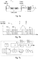
- Figure 1b shows a second exemplary embodiment of a range finder 1.
- the radiation 12 generated by the frequency comb laser 2 is amplified by an optical amplifier 25, for example an EDFA, so that amplified radiation pulses 12 'are emitted.
- the comb laser 2 thus serves as a seed laser for the optical amplifier 25.
- the frequency comb laser 2 serves, more precisely the pulse rate generated by him, as input for a phase locked loop 6 (for this purpose, for example, a photodiode for laser radiation detection is integrated in the frequency comb laser).
- the PLL 6 is used to control or adjust the sampling rate of the analog-digital converter 5 as a function of the pulse rate.
- FIG. 1 schematically shows a preferred embodiment of a freely oscillating frequency comb laser 2.
- the fiber-based laser 2 has a pump diode 13 which, via fibers 14 by means of a coupler 15, combines the power into the cavity consisting of a reflector 16 combined with a saturable absorber (bonded Semiconductor Saturable Absorber -SESAM) and a grating 17 couples as a second reflector.
- a saturable absorber bonded Semiconductor Saturable Absorber -SESAM
- a section of the singlemode fiber 14 is doped with erbium, for example.
- This amplifier unit together with the non-linear transmission of SESAM locking between the many spectral laser modes and in its own state of lowest order causes a stable pulse rate of the laser emission.
- the laser pulses 12 have a duration of less than 10ps, typically ⁇ 1ps.
- the pulse rate is determined by the transit time over the light path between the two resonator mirrors.
- the laser pulse rate can optionally be adjusted by changing the optical path length between the two mirrors.
- a percentage of the power of the pulses is passed through the coupler 15 to the output 12.
- the laser 2 has neither pulse rate stabilization nor CEP stabilization (CEP: carrier envelope phase), which advantageously keeps complexity, size and costs low.
- a fiber-based laser 2 as shown also has a high mechanical stability compared to solid-state free-beam lasers, e.g. against vibrations or shocks, which is particularly advantageous for mobile range finders.
- Figure 3 illustrates an example of setting the sampling rate S to the pulse rate P with the accumulation A of sampling points 18a, b within the scope of the distance measuring method.
- the time axis is shown as the right axis and a signal intensity as the vertical axis.
- the sampling rate is a non-integer multiple of the pulse rate (phase rigidity), the offset in the example being adapted to the number of pulses 13a-13x or their sampling points 18a-18x for an accumulation.
- the sampling points 18a-18x are then repeated with respect to the temporal position on the received signals.
- the scanning pattern repeats after x emitted signals.
- a measurement usually comprises several such cycles, a shortest, meaningful measurement of high quality comprises exactly one cycle of a number x.
- the accumulation A of the sampling points 18a-18x is shown.
- the sampling points 18a-18x are combined to form a digital reception pulse 13D, the combination, as already mentioned above, being carried out without assignment, ie from which “source”, from which reception pulse 13a, 13b ... or 13x the respective sampling point originates is not adopted.
- the assembly is a purely sequential order of the received signal pulses modulo x.
- FIG 4 shows another example of a signal accumulation in the context of the ADC conversion.
- the individual digitized scanning pulses or digital signal vectors (DSV) 13Dx are shown in chronological order, with x in the example being seven.
- These digital signals 13Dx are from the analog receive pulses generated by sampling with the sampling rate S, which in the example is 320 megasamples per second (MS / s).
- a total digital pulse 13D is generated from these x digital pulses 13Dx by accumulation, preferably without assignment (over the period of 4ps) (lower part of the Figure 4 ).
- the combination of all sampling points results in a sampling which corresponds to a sampling rate S * x, which in the example - since seven 13Dx pulses are used - corresponds to seven times the original sampling rate, i.e. 2.24 gigasamples per second in the example.
- Such a procedure, with which a multiplied sampling rate can be provided enables a precise distance measurement even with simple, inexpensive components of a range finder, including above all an ADC converter.
- systematic errors of the electronic reception channel which have synchronous behavior, are averaged out by the asynchronous detection of the reception signals.
- Figure 5 illustrates how a further method of shifting the scanning grating can be implemented as a further development option.
- This second method can be combined with the method described above and as an independent shift of the sampling rate relative to the pulse rate.
- the shift takes place by a fraction of typically less than 1 / x of the transmission pulse frequency, for example by 0.5 ppm in relation to the pulse rate.
- the sampling points are combined without assignment to form a single digitized pulse 13Dx, a slightly washed-out or smeared pulse shape results.
- the subsamples or pulses 13Dx mix after just a few signal pulses, and a sufficient reduction or cancellation of converter errors such as gain errors, timing errors or offset errors, which otherwise have a disruptive effect, particularly in the case of inexpensive AD converters, is already achieved after short measuring times guaranteed.
- Figure 6 an example of a further development of the range finder according to the invention.
- a laser 2 and fibers 14 for guiding the laser light to be emitted are shown.
- the range finder in the example shows the Figure 6 a (fiber-optic) amplitude modulator 19 as a variable optical attenuator, which is controlled in the example via a coaxial cable 20.
- the laser pulse amplitudes are modulated (analogously) in such a way that laser pulses can be distinguished. So there is a modulation - in the example of the amplitudes - such that laser pulses, Pulse groups or envelopes of pulse sequences can be clearly identified. The distance can be clearly determined, even with thousands of pulses between the measuring device and the target.
- the Figures 7a and 7b show another form of ambiguity resolution.
- the device has a pulse picker 21 ( Figure 7a ), which picks out 22 pulses 12 from the sequence of laser pulses generated at the pulse rate or suppresses a part of the pulses 12. Using this discrete modulation, a modified pulse train 22m is created.
- Figure 7b shows a pulse train 22m modulated in this way from radiation pulses 12.
- the original pulse train (22 in Figure 7a ) is interrupted in a targeted manner by means of pulse picking (arrows 23) in such a way that "packets" 24a and 24b of pulses 12 that can be clearly identified are generated, by means of which any ambiguities can be resolved or avoided.
- the amplitude modulation after Figure 6 and a pulse picking after the Figures 7a and 7b can also be combined.
- the number of pulses 12 between sending and receiving is determined.
- the laser 2 has an electro-optical phase shifter instead of outside in the cavity, with which the pulse rate can be changed and at least two different pulse repetition frequencies can be provided. By measuring the received pulses with at least two such frequencies, ambiguities can be resolved — the difference frequency of the two pulse sequence frequencies specifying the maximum possible ambiguity distance — and the distance can be determined absolutely.
- Figure 7c indicates based on Figure 1b a range finder 1 with a pulse picker 21.
- the radiation 12 or pulse train 22 generated by the laser 2 is modulated by means of the pulse picker 21 before it is amplified by the optical amplifier 25, so that a modulated and amplified radiation pulse train 22m1 'is emitted.
- the pulse picking takes place on the basis of a signal from the PLL 6. For example, with an "original" pulse rate of 100 MHz generated by the laser 2, only every 100th pulse is passed, so that radiation 22 is emitted with an effective pulse rate of 1 MHz. If, for example, the (average) power of the laser is 1mW, this is 1 ⁇ W after the pulse picker and is then amplified to 10mW by the amplifier.
- the PLL 6 also regulates the modulation of the pulse sequence 22 generated such that, in addition to the first pulse sequence 22m1, e.g. with every 100th pulse, a second modulated pulse sequence 22m2 is generated, e.g. with passing every 110th pulse.
- the evaluation of the resulting synthetic intermediate frequency of 90.9kHZ resolves ambiguities at a distance of up to 1650m.
Landscapes
- Engineering & Computer Science (AREA)
- Physics & Mathematics (AREA)
- Computer Networks & Wireless Communication (AREA)
- General Physics & Mathematics (AREA)
- Radar, Positioning & Navigation (AREA)
- Remote Sensing (AREA)
- Electromagnetism (AREA)
- Optical Radar Systems And Details Thereof (AREA)
Abstract
Die Erfindung betrifft einen elektrooptischen Entfernungsmesser (1) sowie ein Entfernungsmessverfahren, wobei eine Entfernung zu einem Ziel (100) laufzeitbasiert mittels Strahlungspulsen (12, 13) gemessen wird, welche mit einer Pulsrate emittiert werden. Empfangene Strahlungspulse (13) werden mittels Abtastung digitalisiert, wobei die Abtastrate (S) abhängig von der Pulsrate (P, 22) eingestellt wird, wobei ein digitalisiertes Signal (13D) erzeugt wird anhand Abtastung über die Empfangssignale (13a, 13b, 13c ... 13x) einer Mehrzahl x empfangener Strahlungspulse (13).The invention relates to an electro-optical distance meter (1) and a distance measuring method, wherein a distance to a target (100) is measured based on the transit time by means of radiation pulses (12, 13) which are emitted at a pulse rate. Received radiation pulses (13) are digitized by means of scanning, the sampling rate (S) being set depending on the pulse rate (P, 22), a digitized signal (13D) being generated by means of scanning via the received signals (13a, 13b, 13c .. 13x) a plurality x received radiation pulses (13).
Description
Die Erfindung betrifft einen elektrooptischen Entfernungsmesser nach Anspruch 10 und ein Verfahren zur Entfernungsmessung nach Anspruch 1.The invention relates to an electro-optical distance meter according to
Im Bereich der elektronischen bzw. elektrooptischen Distanzmessung sind verschiedene Prinzipien und Verfahren bekannt. Ein Ansatz besteht darin, gepulste elektromagnetische Strahlung, wie z.B. Laserlicht, auf ein zu vermessendes Ziel, dessen Distanz es zu bestimmen gilt, auszusenden und nachfolgend ein Echo von diesem Ziel als rückstreuendem Objekt zu empfangen. Um den zur Vermessung angezielten Punkt auf dem Zielobjekt erkennbar zu machen, kann dabei sichtbares Licht verwendet werden. Die zurückgeworfene optische Strahlung wird im Gerät von einem photosensitiven Element in ein elektrisches Signal umgewandelt. Vielfach befinden sich dabei im optischen Sende- bzw. Empfangspfad optische Komponenten zur Strahlformung, Umlenkung, Filterung, etc. - wie etwa Linsen, Wellenlängenfilter, Spiegel, usw.Various principles and methods are known in the field of electronic or electro-optical distance measurement. One approach is to use pulsed electromagnetic radiation, e.g. Send laser light to a target to be measured, the distance of which is to be determined, and subsequently receive an echo from this target as a backscattering object. Visible light can be used to make the point aimed for measurement recognizable on the target object. The reflected optical radiation is converted into an electrical signal in the device by a photosensitive element. Often there are optical components for beam shaping, deflection, filtering, etc. in the optical transmission or reception path, such as lenses, wavelength filters, mirrors, etc.
Die Distanz zum zu vermessenden Ziel kann beispielsweise anhand der Laufzeit des Pulses oder Sendemusters, und/oder der Phase des Pulses innerhalb eines Modulationszyklus bestimmt werden. Solche Laserdistanzmesser haben sich mittlerweile in vielen Bereichen, z.B. der Geodäsie oder industriellen Vermessung, als Standardlösungen durchgesetzt, z.B. in Form von Totalstationen, Laserscannern, EDMs oder Lasertrackern. Um eine entsprechend hohe Genauigkeit der Distanzmessung zu erlangen, sind aufgrund der hohen Ausbreitungsgeschwindigkeit von optischer Strahlung im Freiraum die Anforderungen an das zeitliche Auflösungsvermögen zur Distanzmessung recht hoch. Beispielsweise ist bei typischen Messdistanzen für eine Distanzauflösung von 1 mm oder deutlich darunter eine Zeitauflösung mit einer Genauigkeit von mindestens etwa 6,6 Pico-Sekunden erforderlich.The distance to the target to be measured can be determined, for example, on the basis of the transit time of the pulse or transmission pattern and / or the phase of the pulse within a modulation cycle. Such laser distance meters have meanwhile become established as standard solutions in many areas, for example geodesy or industrial surveying, for example in the form of total stations, laser scanners, EDMs or laser trackers. In order to achieve a correspondingly high accuracy of the distance measurement, due to the high speed of propagation of optical radiation in the free space The temporal resolution requirements for distance measurement are quite high. For example, with typical measuring distances for a distance resolution of 1 mm or significantly less, a time resolution with an accuracy of at least about 6.6 pico-seconds is required.
Für ein möglichst deutliches und damit präzise auswertbares Empfangssignal ist eine möglichst hohe Ausgangsleistung wünschenswert. Bezüglich der emittierbaren Signalleistung sind den hier behandelten elektrooptischen Geräten jedoch Grenzen vorgegeben. So bestimmt bei der Emission von Laserlicht die Augensicherheit eine maximal zulässige mittlere Signalleistung, welche emittiert werden darf. Um für die Messung dennoch hinreichend starke Signalintensitäten zu erhalten, welche vom Empfänger detektierbar sind, wird daher vorzugsweise im Pulsbetrieb gearbeitet. Es werden kurze Pulse mit hoher Spitzenleistung gefolgt von Pausen ohne Signalaussendung ausgesendet. Somit weist der zurückgeworfene Anteil der Pulse eine genügend hohe Intensität auf, um diese aus den Hintergrundstörungen und dem Rauschen, insbesondere auch bei Vorhandensein von Hintergrundlicht (Sonnenlicht, künstlicher Beleuchtung, etc.), mit hohem Signal-zu-Rauschverhältnis auswerten zu können.For a reception signal that is as clear as possible and thus can be evaluated precisely, the highest possible output power is desirable. However, limits are imposed on the electro-optical devices dealt with here with regard to the emittable signal power. For example, when laser light is emitted, eye safety determines a maximum permissible mean signal power that may be emitted. In order to obtain sufficiently strong signal intensities for the measurement which can be detected by the receiver, work is therefore preferably carried out in pulse mode. Short pulses with high peak power are sent out followed by pauses without signal transmission. The reflected portion of the pulses thus has a sufficiently high intensity to be able to evaluate them from the background interference and the noise, in particular also in the presence of background light (sunlight, artificial lighting, etc.), with a high signal-to-noise ratio.
Bekannte Lichtquellen mit zum System synchronen Puls- oder Modulationsfolgen hoher Spitzenleistung sind beispielsweise elektronisch gepulste Laserdioden oder superlumineszente Leuchtdioden kombiniert mit optischen Verstärkern. All diese Lichtquellen haben den Nachteil, dass die Pulse mehrere 100 Picosekunden lang sind und bei Messungen auf raue natürliche Oberflächen durch räumliche und chromatische Irregularitäten Distanzmessfehler von typisch 0.1mm bis 2mm erzeugen.Known light sources with synchronous pulse or modulation sequences of high peak power are, for example, electronically pulsed laser diodes or superluminescent light emitting diodes combined with optical amplifiers. All these light sources have the disadvantage that the pulses are several 100 picoseconds long and, when measuring on rough natural surfaces, generate spatial measurement errors of typically 0.1 mm to 2 mm due to spatial and chromatic irregularities.
Bekannt sind Güte geschaltete (Q-switched) Festkörperlaser, mit recht kurzen Pulsen bis in den Bereich von 200ps, und einer Pulsrate von wenigen MHz. Ein Nachteil hingegen ist das zeitliche Rauschen der Pulsrate, dieses beträgt in der Regel 1% bis 5% des Pulsintervalls. Die Handhabung dieser Unregelmässigkeit in präzisen Distanzmesssystemen verlangt nach einer komplexen Vorrichtung und entsprechend anspruchsvollem Auswerteverfahren.Quality-switched (Q-switched) solid-state lasers are known, with quite short pulses in the range of 200ps, and a pulse rate of a few MHz. A disadvantage, however, is the temporal noise of the pulse rate, which is usually 1% to 5% of the pulse interval. The handling of this irregularity in precise distance measuring systems requires a complex device and a correspondingly sophisticated evaluation method.
Bekannt sind dabei im Bereich der interferometrischen Entfernungsmessung mit Pulsbetrieb auch Distanzmesser mit stabilisiertem Frequenzkammlaser, z.B. aus der
Zur Ermittlung der Laufzeit des Signals ist zum einen das so genannte Phasenmessprinzip bekannt, welches die Signallaufzeit durch Vergleich der Phasenlage der Amplitudenmodulation des gesendeten und empfangenen Signals ermittelt.To determine the transit time of the signal, on the one hand, the so-called phase measurement principle is known, which determines the signal transit time by comparing the phase position of the amplitude modulation of the transmitted and received signal.
Zum anderen ist die so genannte Time-of-Flight (TOF) Methode bekannt, welche die Zeit zwischen dem Aussenden und Empfangen eines Lichtpulses ermittelt, wobei die Zeitmessung anhand der Flanke, des Spitzenwerts, oder einer anderen Charakteristik der Pulsform erfolgt. Unter Pulsform ist dabei ein zeitlicher Lichtintensitätsverlauf des Empfangssignals, speziell des empfangenen Lichtpulses - erfasst durch das photosensitive Element - zu verstehen. Dabei kann der Zeitpunkt des Sendens entweder anhand eines elektrischen Auslöseimpulses, des an den Sender angelegten Signals oder anhand des oben erwähnten Referenzsignals ermittelt werden.On the other hand, the so-called time-of-flight (TOF) method is known, which determines the time between the transmission and reception of a light pulse, the time being measured on the basis of the edge, the peak value, or another characteristic of the pulse shape. Under pulse shape is a temporal light intensity curve of the received signal, especially the received light pulse - detected by the photosensitive element. The time of transmission can be determined either on the basis of an electrical trigger pulse, the signal applied to the transmitter or on the basis of the reference signal mentioned above.
In der Distanzmessung kann es dabei zu Mehrdeutigkeiten kommen, falls die Signallaufzeit den Kehrwert der Puls-Senderate übersteigt und somit mehrere identische Signale zugleich zwischen Gerät und Messobjekt unterwegs sind, wodurch ein Empfangspuls nicht mehr eindeutig seinem jeweiligen Sendepuls zugeordnet werden kann. Es ist somit ohne weitere Maßnahmen unklar, ob die Distanz oder die Teildistanz als Divisionsrest durch die Sendepulsperiode gemessen wurde.There may be ambiguities in the distance measurement if the signal transit time exceeds the reciprocal of the pulse transmission rate and thus several identical signals are traveling between the device and the device under test, which means that a reception pulse can no longer be clearly assigned to its respective transmission pulse. It is therefore unclear without further measures whether the distance or the partial distance was measured as the remainder of the division through the transmission pulse period.
Zur Detektion des zurückgestreuten Pulses werden zumeist zwei unterschiedliche Ansätze oder eine Kombination daraus verwendet.Two different approaches or a combination thereof are usually used to detect the backscattered pulse.
Bei der Time-of-Flight Methode nach dem so genannten Schwellwertprinzip wird ein Lichtpuls detektiert, wenn die Intensität der auf einen Detektor des eingesetzten Distanzmessgeräts einfallenden Strahlung einen gewissen Schwellwert überschreitet. Durch diesen Schwellwert wird verhindert, dass Rauschen und Störsignale aus dem Hintergrund fälschlich als Nutzsignal, d.h. als rückgestreutes Licht des emittierten Pulses, detektiert werden.In the time-of-flight method based on the so-called threshold value principle, a light pulse is detected when the intensity of the radiation incident on a detector of the distance measuring device used exceeds a certain threshold value. This threshold value prevents noise and interference signals from the background being erroneously used as a useful signal, i.e. as backscattered light of the emitted pulse.
Der andere Ansatz der Time-of-Flight Methode basiert auf der Abtastung bzw. dem Sampling des rückgestreuten Pulses. Dieser Ansatz wird typischerweise bei schwachen rückgestreuten Signalen (z.B. Pulssignale) verwendet, wie sie beispielsweise durch grössere Messdistanzen bedingt werden, oder allgemein für eine Erhöhung der Messgenauigkeit. Ein emittiertes Signal wird detektiert, indem die von einem Detektor erfasste Strahlung abgetastet, innerhalb des abgetasteten Bereichs ein Signal identifiziert und schliesslich eine Lage des Signals zeitlich bestimmt wird. Durch die Verwendung einer Vielzahl von Abtastwerten und/oder zur Emissionsrate synchronem Aufsummieren des Empfangssignals kann ein Nutzsignal auch unter ungünstigen Umständen identifiziert werden, so dass auch grössere Distanzen oder verrauschte bzw. mit Störungen behaftete Hintergrundszenarien bewältigt werden können. Beim Ansatz der zeitlich sehr präzisen Abtastung bzw. dem Sampling des zurückgestreuten Signals, wird das vom Detektor erzeugte elektrische Signal mittels eines Analog-Digital-Wandlers ("Analog-Digital-Converter", ADC) in eine digitale Signalfolge umgewandelt.The other approach of the time-of-flight method is based on the sampling or sampling of the backscattered pulse. This approach is typically used in the weak backscattered signals (eg pulse signals) are used, such as those caused by larger measuring distances, or generally to increase the measuring accuracy. An emitted signal is detected by scanning the radiation detected by a detector, identifying a signal within the scanned area and finally determining the position of the signal over time. By using a large number of sampled values and / or summing up the received signal synchronously with the emission rate, a useful signal can also be identified under unfavorable circumstances, so that even larger distances or noisy background scenarios or those with disturbances can be dealt with. In the case of the very precise sampling or sampling of the backscattered signal, the electrical signal generated by the detector is converted into a digital signal sequence by means of an analog-digital converter ("analog-digital converter", ADC).
Bei schnellen Analog-Digital-Wandlern (ADC) wird eine hohe Abtastrate in Verbindung mit einer hohen Auflösung der Signalamplitude (z.B. 1GS/s, 14bit) beispielsweise erreicht durch die Erzeugung mehrere ADC-Wandlungsstufen, z durch ein zeitliches Verschachteln ("interleave", "interleaving") mehrerer langsamer ADC-Wandlungsstufen, ein stufenweises Quantisieren der abgetasteten Signalamplituden ("pipeline", "pipelining"), oder kombiniert ein mehrstufiges Quantisieren der Signalabtastwerte von mehreren ADC-Wandlungsstufen. Nachteilig an derartigen ADCs bzw. derartigen Methoden ist der hohe Aufwand, welcher sich auch in hohen Herstellungskosten niederschlägt.In the case of fast analog-digital converters (ADC), a high sampling rate in connection with a high resolution of the signal amplitude (for example 1 GS / s, 14 bit) is achieved, for example, by generating several ADC conversion stages, for example by interleaving over time ("interleave", "interleaving") several slow ADC conversion stages, a step-by-step quantization of the sampled signal amplitudes ("pipeline", "pipelining"), or combines a multi-stage quantization of the signal samples from several ADC conversion stages. A disadvantage of such ADCs or methods of this type is the high outlay, which is also reflected in high production costs.
Aufgabe der Erfindung ist daher die Bereitstellung eines einfachen bzw. vereinfachten Entfernungsmessers und Entfernungsmessverfahrens, mit dem hochpräzise, insbesondere absolute, Distanzmessungen ermöglicht sind.The object of the invention is therefore to provide a simple or simplified range finder and Distance measuring method with which highly precise, in particular absolute, distance measurements are made possible.
Diese Aufgabe wird durch die Verwirklichung der kennzeichnenden Merkmale der unabhängigen Ansprüche gelöst. Merkmale, die die Erfindung in alternativer oder vorteilhafter Weise weiterbilden, sind den abhängigen Patentansprüchen zu entnehmen.This object is achieved by realizing the characterizing features of the independent claims. Features which further develop the invention in an alternative or advantageous manner can be found in the dependent claims.
Die Erfindung betrifft ein Verfahren zur Entfernungsmessung. Im Rahmen des Entfernungsmessverfahrens erfolgt ein Aussenden von gepulster optischer Strahlung mit einer Pulsrate, welche vorzugsweise mindestens 1 MHz beträgt. Vorzugsweise wird dabei die Strahlung von einem Frequenzkamm-Laser erzeugt. Weiter erfolgen ein Empfangen eines von einem Zielobjekt zurückgeworfenen Anteils der optischen Strahlung mit einem photosensitiven elektrischen Empfangselement und ein Umwandeln in ein elektrisches Empfangssignal, ein Abtasten des, optional gefilterten, Empfangssignals mit einer Abtastrate, so dass anhand von dabei erzeugten Abtastpunkten ein digitalisiertes Signal erzeugt wird, sowie ein Auswerten des digitalisierten Signals zur Bestimmung der Signallaufzeit zwischen Aussenden und Empfangen zum Ermitteln der Entfernung anhand der Signallaufzeit.The invention relates to a method for distance measurement. Within the scope of the distance measuring method, pulsed optical radiation is emitted at a pulse rate, which is preferably at least 1 MHz. The radiation is preferably generated by a frequency comb laser. Furthermore, a portion of the optical radiation reflected by a target object is received with a photosensitive electrical reception element and converted into an electrical reception signal, the optionally filtered reception signal is sampled at a sampling rate, so that a digitized signal is generated on the basis of sampling points generated in the process , and an evaluation of the digitized signal to determine the signal transit time between transmission and reception to determine the distance based on the signal transit time.
Die Abtastrate ist dabei abhängig von der Pulsrate eingestellt, wobei vorzugsweise die Abtastrate mindestens zehnmal die Pulsrate beträgt. Weiter erfolgt das Abtasten über eine Mehrzahl empfangener Strahlungspulse. Hierzu wird vorzugsweise die Pulsrate, insbesondere fortwährend, gemessen und die Abtastrate, insbesondere fortwährend, in Abhängigkeit der gemessenen Pulsrate eingestellt. Optional wird dabei auch die sich ergebende Abtastrate mittels einer externen bzw. unabhängigen Zeitbasis (z.B. mit einem Zähler) absolut bestimmt. Alternativ werden Pulsrate und an diese angepasst auch die Abtastrate anhand vorgegebener Taktraten, insbesondere fortlaufend, eingestellt, wobei die Taktrate z.B. mittels eines unabhängigen Taktgenerators erzeugt wird.The sampling rate is set as a function of the pulse rate, the sampling rate preferably being at least ten times the pulse rate. Furthermore, the scanning takes place via a plurality of received radiation pulses. For this purpose, the pulse rate is preferably measured, in particular continuously, and the sampling rate, in particular continuously, is set as a function of the measured pulse rate. The resulting sampling rate is also optional using a external or independent time base (e.g. with a counter) absolutely determined. Alternatively, the pulse rate, and the sampling rate adapted to this, are set using predetermined clock rates, in particular continuously, the clock rate being generated, for example, by means of an independent clock generator.
Vorzugsweise wird die Abtastrate in einem solchen Verhältnis zur Pulsrate eingestellt, dass Abtastrate und Pulsrate zueinander phasenstarr sind. Vorzugsweise wird die Abtastrate dabei so eingestellt, dass sie ein nicht-ganzzahliges Vielfaches der Pulsrate ist, wobei für das Verhältnis von Abtastrate zu Pulsrate beispielsweise entweder gilt: ![]()
![]()
![]()
![]()
Optional ist die Abtastrate wesentlich kleiner als die Bandbreite der Empfangseinheit (Unterabtasten) und/oder das pulsratenabhängige Einstellen der Abtastrate erfolgt algorithmisch, also ein rechnerisches, auswerteseitiges Anpassen der Abtastrate - z.B. als Resampling- an die Pulsrate.Optionally, the sampling rate is significantly smaller than the bandwidth of the receiving unit (subsampling) and / or the pulse rate-dependent setting of the sampling rate is carried out algorithmically, i.e. a computational, evaluation-side adjustment of the sampling rate - e.g. as resampling to the pulse rate.
In einer Fortbildung wird das digitalisierte Signal erzeugt, indem die Abtastpunkte der Mehrzahl der empfangenen Strahlungspulse akkumuliert werden, wobei dies vorzugsweise bezüglich der einzelnen Strahlungspulse zuordnungslos erfolgt. Alternativ oder zusätzlich werden die Abtastpunkte herangezogen, um Parameterwerte von Polynomen zu optimieren, welche das Signal oder die Signalform beschreiben, insbesondere in Echtzeit.In a further development, the digitized signal is generated in that the sampling points of the plurality of received radiation pulses are accumulated, this preferably taking place without assignment with respect to the individual radiation pulses. Alternatively or additionally, the sampling points are used to optimize parameter values of polynomials that describe the signal or the signal shape, in particular in real time.
Dabei erfolgt das Abtasten optional derart, dass sich die Abtastpunkte nach der Mehrzahl wiederholen und für das Erzeugen des digitalisierten Signals ein Vielfaches der sich wiederholenden Abtastpunkte herangezogen wird. Mit anderen Worten wiederholt sich ein Abtastmuster nach einer gewissen Anzahl an Abtastpunkten, so dass ein Abtasten der Pulse zu sich wiederholenden Zeitpunkten erfolgt und es wird dann beispielsweise über mehrere solcher Wiederholungen akkumuliert. Nach x Pulsen wiederholt sich also jeweils das Abtastraster an der Pulsform.The sampling is optionally carried out in such a way that the sampling points are repeated after the plurality and a multiple of the repeating sampling points is used to generate the digitized signal. In other words, a sampling pattern repeats itself after a certain number of sampling points, so that the pulses are sampled at repeating points in time and it is then accumulated, for example, over a number of such repetitions. After x pulses, the scanning grid repeats on the pulse shape.
In einer weiteren Fortbildung erfolgt ein Einstellen einer (leichten) Asynchronizität der Abtastrate zur Pulsrate um einen zusätzlichen Bruchteil (y, z.B. als ppm ausgedrückt) grösser als ein Mehrfaches der Sendepulsrate, insbesondere höchstens ein Millionstel, so dass ein (kontrolliertes) Phasengleiten bzw. ein Abtasten ohne Wiederholung von Abtastpunkten erfolgt. Dieser Phase-Slip mittels Frequenzoffset ist optional auch mit dem oben beschriebenen Verhältnis von Abtastrate zu Pulsrate kombinierbar, formelhaft ausgedrückt also: ![]()
![]()
Optional wird dabei die Abtastrate akkumulierend um diesen Bruchteil von Abtastung zu Abtastung verschoben. Bei einer Akkumulation über eine Zeit TAcc verschiebt sich somit das Samplingraster um eine Zeit ΔT zum Laserpuls: ![]()
![]()
Als weitere Option werden etwaige Ambiguitäten bei der Entfernungsbestimmung mittels diskretem und/oder analogem Modulieren der Strahlungspulsfolge aufgelöst, wobei optional hierbei ein Bestimmen der Anzahl der Strahlungspulse zwischen Aussenden und Empfangen erfolgt.As an additional option, any ambiguities in the distance determination using discrete and / or analog Modulation of the radiation pulse sequence is resolved, with the number of radiation pulses between sending and receiving being optionally determined.
Die Erfindung betrifft zudem einen elektrooptischen Entfernungsmesser, insbesondere Laser-Distanzmesser. Das Entfernungsmessgerät weist eine Strahlungsquelle zur Erzeugung von gepulster Strahlung mit einer Pulsrate auf, sowie ein optisches Objektiv und ein photosensitives Bauelement, insbesondere eine Photodiode, zum Empfang eines von einem Zielobjekt zurückgeworfenen Anteils der Strahlung und Umwandlung in ein Empfangssignal, und einen Analog-Digital-Wandler (ADC) zur Digitalisierung des Empfangssignals mittels Abtastung mit einer Abtastrate. Darüber hinaus weist der Entfernungsmesser eine elektronische Auswerteeinheit oder Auswerteelektronik auf, welche auf Basis einer Signallaufzeit anhand des digitalisierten Empfangssignals eine Entfernung zwischen Entfernungsmesser und Zielobjekt ermittelt, wobei die Entfernung vorzugsweise absolut messbar ist.The invention also relates to an electro-optical rangefinder, in particular a laser rangefinder. The distance measuring device has a radiation source for generating pulsed radiation with a pulse rate, and an optical lens and a photosensitive component, in particular a photodiode, for receiving a portion of the radiation reflected by a target object and converting it into a received signal, and an analog-digital signal. Converter (ADC) for digitizing the received signal by means of sampling at a sampling rate. In addition, the rangefinder has an electronic evaluation unit or evaluation electronics, which determines a distance between the rangefinder and the target object on the basis of a signal delay based on the digitized received signal, the distance preferably being absolutely measurable.
Der Entfernungsmesser weist weiter eine Abtastfunktionalität auf, bei deren Ausführung die Abtastrate abhängig von der Pulsrate eingestellt wird, wobei die Abtastrate vorzugsweise wenigstens zehnmal so gross ist wie die Pulsrate. Weiter erfolgt die Abtastung zur Digitalisierung des jeweiligen, für eine Entfernungsermittlung herangezogenen Empfangssignals über eine Mehrzahl x empfangener Strahlungspulse.The rangefinder also has a scanning functionality, in the execution of which the sampling rate is set as a function of the pulse rate, the sampling rate preferably being at least ten times the pulse rate. Furthermore, the scanning for digitizing the respective received signal used for determining the distance takes place via a plurality x received radiation pulses.
In einer bevorzugten Ausführungsform ist die Strahlungsquelle ein freilaufender, frequenzstabilisierungsloser Frequenzkammlaser. Optional ist der Frequenzkammlaser ausgebildet zur Erzeugung von Pulsen mit einer Pulsdauer zwischen 100fs und 10ps und/oder ausgebildet als Mikro-Frequenzkammlaser mit wenigstens einem monolithischen Mikroresonator (Optical Whispering-Gallery Mode Resonator).In a preferred embodiment, the radiation source is a free-running, frequency stabilization-free frequency comb laser. The is optional Frequency comb laser designed to generate pulses with a pulse duration between 100fs and 10ps and / or designed as a micro frequency comb laser with at least one monolithic microresonator (Optical Whispering-Gallery Mode Resonator).
Vorzugsweise ist der Entfernungsmesser ausgebildet, die Pulsrate, vorzugsweise fortlaufend, z.B. mittels eines geräteinternen Strahlungsdetektors, zu erfassen und die Abtastrate in Abhängigkeit der erfassten Pulsrate, insbesondere mittels einer Phasenregelschleife (PLL) einzustellen, vorzugsweise fortlaufend und/oder asynchron. Optional weist der Entfernungsmesser zur Einstellung der Abtastrate anhand der gemessenen Pulsrate einen ersten Taktgenerator, insbesondere eine Phasenregelschleife (PLL), auf, der mittels der erfassten Pulsrate die Abtastrate erzeugt, so dass der Laser als rauscharme Zeitbasis für den ersten Taktgenerator dient, wobei der erste Taktgenerator die Pulsrate einer weiteren Einheit weiter gibt, um die exakte Pulsrate des Lasers zu messen. Dies erfolgt beispielsweise in einem FPGA, welcher von einer genauen Zeitbasis (TCXO, OCXO) getaktet wird. Die Kenntnis der genauen Abtastrate ist Basis zur genauen Entfernungsermittlung.Preferably, the range finder is designed, the pulse rate, preferably continuously, e.g. by means of a device-internal radiation detector, and to set the sampling rate depending on the detected pulse rate, in particular by means of a phase locked loop (PLL), preferably continuously and / or asynchronously. Optionally, the distance meter for setting the sampling rate based on the measured pulse rate has a first clock generator, in particular a phase locked loop (PLL), which generates the sampling rate by means of the detected pulse rate, so that the laser serves as a low-noise time base for the first clock generator, the first Clock generator passes on the pulse rate of another unit to measure the exact pulse rate of the laser. This takes place, for example, in an FPGA, which is clocked by an exact time base (TCXO, OCXO). Knowing the exact sampling rate is the basis for determining the exact distance.
Optional weist der Entfernungsmesser wenigstens einen unabhängigen Taktgenerator, insbesondere einen temperaturkompensierten (Kristall-)Oszillator (TCO bzw. TCXO oder OCXO), zur Erzeugung einer unabhängigen Taktrate auf. Bei Ausführung der Abtastfunktionalität können dann, vorzugsweise fortwährend, die Abtastrate und die Pulsrate basierend auf der Taktrate eingestellt werden. Zusätzlich oder alternativ kann anhand der Taktrate fortwährend die absolute Frequenz der Strahlung bestimmt werden, wobei der Entfernungsmesser ausgebildet ist, einen Abtast- zu Entfernungsfaktor laufend zu berechnen, so dass die Entfernungsbestimmung mit einem Skalenfehler kleiner als 10ppm, aber auch kleiner als 1ppm ermöglicht ist.The range finder optionally has at least one independent clock generator, in particular a temperature-compensated (crystal) oscillator (TCO or TCXO or OCXO), for generating an independent clock rate. When the sampling functionality is carried out, the sampling rate and the pulse rate can then, preferably continuously, be set based on the clock rate. Additionally or alternatively, the absolute frequency of the radiation are determined, the range finder being designed to continuously calculate a scanning to distance factor, so that the distance determination with a scale error of less than 10ppm but also less than 1ppm is possible.
Optional weist das photosensitive elektrische Bauelement eine Bandweite im Gigahertzbereich auf, wobei es optional als Avalanche-Photodiode (APD) oder Single-Photon-Avalanche-Photodioden (SPAD)-Array ausgebildet ist. Als weitere Option weist der Entfernungsmesser einen faseroptischen Strahlungsverstärker und/oder ein internes Referenzziel auf, wobei anhand des Referenzziels ein optischer Referenzpfad zur absoluten Referenzierung der Entfernungsermittlung bereitstellbar ist.The photosensitive electrical component optionally has a bandwidth in the gigahertz range, it optionally being designed as an avalanche photodiode (APD) or a single photon avalanche photodiode (SPAD) array. As a further option, the range finder has a fiber-optic radiation amplifier and / or an internal reference target, an optical reference path for absolute referencing of the distance determination being able to be provided on the basis of the reference target.
Vorzugsweise weist der Entfernungsmesser zur Auflösung von Ambiguitäten bei der Ermittlung der Entfernung einen Modulator auf zur Modulation der Laserpulse, insbesondere ein variables optisches Dämpfungsglied (VOA) ausserhalb der Laserkavität zur Erzeugung eines amplitudenmodulierten Signals mit konstanter Frequenz. Eine Modulation erfolgt alternativ oder zusätzlich mittels eines Puls-Pickers, der beispielsweise bei einer ursprünglichen Pulsrate von 10MHz nur jeden neunten oder zehnten Puls in einen optischen Verstärker bzw. zur Emission auf das Ziel durchlässt. Als weitere Option zur Ambiguitätenauflösung weist das Gerät einen elekro-optischen Phasenschieber im Innern einer Kavität des Lasers zur Erzeugung wenigstens zweier unterschiedlicher Pulsfolgefrequenzen auf.The range finder for resolving ambiguities when determining the distance preferably has a modulator for modulating the laser pulses, in particular a variable optical attenuator (VOA) outside the laser cavity for generating an amplitude-modulated signal with a constant frequency. Modulation is carried out alternatively or additionally by means of a pulse picker which, for example at an original pulse rate of 10 MHz, only lets every ninth or tenth pulse into an optical amplifier or for emission to the target. As a further option for ambiguity resolution, the device has an electro-optical phase shifter inside a cavity of the laser for generating at least two different pulse repetition frequencies.
Optional ist der Entfernungsmesser zur spektralen Interferometrie ausgebildet. Dabei erfolgt als Option im Rahmen der Entfernungsbestimmung ein Frequenzabstimmen der Pulsrate, so dass mittels Pulsüberlapp Interferenz zwischen einem Referenzpuls und einem Empfangspuls nutzbar ist, und/oder ein spektrales Aufteilen der empfangenen Pulse mittels eines dispersiven Elements, insbesondere eines Gitters oder Virtual Imaged Phased Array (VIPA), und Intensitätsmessung mittels einer Kamera des Entfernungsmessers und/oder eine Reduktion des Pulsintervalls mittels einer empfangsseitigen Ringkavität des Entfernungsmessers, vorzugsweise im Referenzlichtpfad,und/oder ein Aufweiten der Pulsform (pulse stretching) mittels auskoppelnder Fabry-Perot Kavität und Gitter des Entfernungsmessers.The range finder is optionally designed for spectral interferometry. As an option, frequency tuning is carried out as part of the distance determination Pulse rate, so that interference between a reference pulse and a receiving pulse can be used by means of pulse overlap, and / or spectral division of the received pulses by means of a dispersive element, in particular a grating or virtual imaged phased array (VIPA), and intensity measurement by means of a camera of the range finder and / or a reduction of the pulse interval by means of a ring cavity of the range finder on the receiving side, preferably in the reference light path, and / or a broadening of the pulse shape (pulse stretching) by means of a decoupling Fabry-Perot cavity and grid of the range finder.
Das erfindungsgemässe Verfahren und die erfindungsgemässe Vorrichtung bieten den Vorteil, dass auch mit kostengünstigen Bauteilen, vor allem einem einfachen ADC und einfachen Frequenzkammlaser, präzise Entfernungsmessungen, bis hin zu Auflösungen im Mikrometer- oder Nanometerbereich, selbst bei grossen Entfernungen zum Ziel (500m oder mehr), ermöglich sind. Ein einfacher ADC ist u.a. durch eine vergleichsweise niedrige Samplingrate, niedrigen Leistungsverbrauch und systematische Fehlereinflüsse wie ungenaue interne Kalibration gekennzeichnet.The method according to the invention and the device according to the invention offer the advantage that even with inexpensive components, especially a simple ADC and simple frequency comb laser, precise distance measurements, up to resolutions in the micrometer or nanometer range, even at great distances to the target (500 m or more) , are possible. A simple ADC includes characterized by a comparatively low sampling rate, low power consumption and systematic error influences such as inaccurate internal calibration.
Durch das Koppeln oder Anpassen der Abtastrate an die Pulsrate können dennoch hohe, vielmehr erhöhte finale Samplingraten bzw. eine hohe Dichte an Abtastpunkten bereitgestellt werden, dies selbst bei Pulsraten im MHz-Bereich, wobei zur weiteren Verringerung der Komplexität bei der Mehrfachabtastung auf eine Zuordnung von Abtastpunkten zu den "originalen" Empfangssignalen verzichtet werden kann.By coupling or adapting the sampling rate to the pulse rate, high, rather increased, final sampling rates or a high density of sampling points can nevertheless be provided, even with pulse rates in the MHz range, with the complexity of multiple sampling being further reduced to an assignment of Sampling points to the "original" received signals can be omitted.
Frequenzkammlaser bieten dabei den Vorteil, dass aufgrund der sehr kurzen Pulsdauer die störenden Einflüsse sog. Speckles im Vergleich zu anderen Lasern drastisch reduziert sind, was sich besonders bei Zielen mit ungleichmässiger Oberfläche vorteilhaft auf die Messpräzision mit Signallaufzeit auswirkt. Der Frequenzkammlaser der Vorrichtung weist weder eine Pulsratenstabilisierung noch eine CEP Stabilisierung auf, dies reduziert die Komplexität, die Baugrösse und die Kosten erheblich. Frequenzkammlaser ohne Stabilisierung der Pulsrate und optischen Trägerphase haben extrem kurze Pulse und daher geringe räumliche und chromatische Irregularitäten. Mit dem vorgestellten Einstellen der Abtastrate in Abhängigkeit wird das Problem gelöst, dass die Laserpulsrate eines unstabilisierten Frequenzkammlasers an sich zum ppm- oder sub-ppm-genauen elektronischen Masteroszillator eines Distanzmesssystems asynchron läuft.Frequency comb lasers offer the advantage that due to the very short pulse duration, the disturbing influences of so-called speckles are drastically reduced compared to other lasers, which has an advantageous effect on measurement precision with signal propagation time, particularly for targets with an uneven surface. The frequency comb laser of the device has neither a pulse rate stabilization nor a CEP stabilization, this considerably reduces the complexity, the size and the costs. Frequency comb lasers without stabilization of the pulse rate and optical carrier phase have extremely short pulses and therefore low spatial and chromatic irregularities. With the presented setting of the sampling rate depending on the problem is solved that the laser pulse rate of an unstabilized frequency comb laser itself runs asynchronously to the ppm or sub-ppm-accurate electronic master oscillator of a distance measuring system.
Ausserdem wird mit der vorliegenden Erfindung ein sog. Distanzzittern (distance jitter) weitgehend vermieden. Dies ist sogar derart gering, dass interferometrische Distanzmessungen ermöglicht sind, obwohl weder eine aktive Puls-zu-Puls-Stabilisierung noch eine Stabilisierung der optischen Phase erfolgt. Die kurzen Laserpulse, z.B. im Femtosekundenbereich, ermöglichen akkurate Einzelschussmessungen, auch auf kurze Distanzen (z.B. weniger als 20m) und auch mit geringer Anzahl an empfangenen Photonen pro Empfangspuls. Das sog. shot-noise-level einer Distanzmessung ist weit unterhalb eines Mikrometers.In addition, a so-called distance jitter is largely avoided with the present invention. This is even so small that interferometric distance measurements are possible, although neither an active pulse-to-pulse stabilization nor a stabilization of the optical phase takes place. The short laser pulses, e.g. in the femtosecond range, enable accurate single-shot measurements, even at short distances (e.g. less than 20m) and also with a small number of photons received per received pulse. The so-called shot noise level of a distance measurement is far below a micrometer.
Das erfindungsgemässe Verfahren und die erfindungsgemässe Vorrichtung werden nachfolgend anhand von in den Zeichnungen schematisch dargestellten konkreten Ausführungsbeispielen rein beispielhaft näher beschrieben, wobei auch auf weitere Vorteile der Erfindung eingegangen wird.The method according to the invention and the device according to the invention are described in more detail below purely by way of example using concrete exemplary embodiments schematically illustrated in the drawings, wherein further advantages of the invention are also discussed.
Im Einzelnen zeigen:
- Fig. 1a,b
- je eine beispielhafte Ausführungsform eines erfindungsgemässen Entfernungsmessers bzw. Entfernungsmessverfahrens;
- Fig. 2
- eine bevorzugte Ausführungsform eines frei oszillierenden Frequenzkammlasers;
- Fig. 3
- ein Beispiel für ein Einstellen der Abtastrate zur Pulsrate mit Akkumulation von Abtastpunkten;
- Fig. 4
- ein weiteres Beispiel für eine Signalakkumulation;
- Fig. 5
- ein Beispiel für ein zusätzliches Verschieben der Abtastrate relativ zur Pulsrate;
- Fig. 6
- eine erste Ausführungsform zur Auflösung von Messambiguitäten; und
- Fig. 7a,b,c
- weitere Ausführungsformen zur Auflösung von Messambiguitäten.
- 1a, b
- each an exemplary embodiment of a rangefinder or distance measuring method according to the invention;
- Fig. 2
- a preferred embodiment of a freely oscillating frequency comb laser;
- Fig. 3
- an example of setting the sampling rate to the pulse rate with the accumulation of sampling points;
- Fig. 4
- another example of signal accumulation;
- Fig. 5
- an example of an additional shifting of the sampling rate relative to the pulse rate;
- Fig. 6
- a first embodiment for the resolution of measurement ambiguities; and
- 7a, b, c
- further embodiments for the resolution of measurement ambiguities.
Vorzugsweise beträgt dabei die jeweilige Pulsdauer zwischen 100fs und 10ps, wobei die Pulslänge z.B. mittels dispergierender Elemente festlegbar ist. Als Option ist der Laser als Mikro-Frequenzkammlaser ausgebildet mit einem monolithischen Mikroresonator zur Erzeugung einer Soliton-Pulsfolge. Als weitere Option weist der Laser 2 eine optische, bspw. faserbasierte Verstärkereinheit auf, z.B. ein Erbium dotierter Faserverstärker (EDFA) mit Singlemode-Faser (siehe auch
Die Laserpulse 12 werden über eine optische Objektivanordnung 14 auf ein Ziel 100 emittiert, wobei ein Teil der Pulse 12a mittels eines teildurchlässigen Spiegels 6s ausgekoppelt werden, so dass die Strahlung 12 teilweise auf einen Photodetektor 3, z.B eine GHz-Photodiode, gelenkt wird. Vom Ziel 100 zurückgeworfene Pulse 13 werden mittels einer Empfangseinheit, im Beispiel mittels des Objektivs 14 (oder einer zusätzlichen Empfangs- Objektivanordnung) und dem Spiegel 6s auf ein weiteres photosensitives elektrisches Bauelement 4 gelenkt. Der Detektor 4 weist vorzugsweise eine Bandweite im Gigahertzbereich auf und ist z.B. eine Avalanche-Photodiode (APD) oder ein Single-Photon-Avalanche-Photodiodenarray (SPAD). Der Detektor 4 verhält sich energiesensitiv, so dass die von den ultrakurzen Laserpulsen freigesetzten Elektronen nicht verlorengehen, sondern zum elektrischen Detektorsignal beitragen.The
Als weitere, nicht dargestellte Option weist der Entfernungsmesser 1 empfängerseitig einen faseroptischen, z.B. dotierten Strahlungsverstärker auf. Das elektrische Empfangssignal des Photosensors 4 wird an einen Analog-Digital-Wandler (ADC) 5 transferiert, wo es mittels Abtasten mit einer Abtastrate (Sampling) digitalisiert wird. Optional weist der Entfernungsmesser 1 in an sich bekannter Weise dabei einen dem ADC 5 vorgeschalteten Signalfilter zur Verbesserung des Signal-Rauschverhältnisses auf.As a further option, not shown, the
Die Abtastrate ist dabei abhängig von der Pulsrate eingestellt, wobei die Abtastrate vorzugsweise mindestens das Zehnfache der Pulsrate beträgt. Im Beispiel erfolgt dieses pulsratenabhängige Einstellen, indem mittels des Detektors 3 und eines Zählers 11 die Pulsrate fortwährend (kontinuierlich) gemessen wird, wobei im Beispiel der Zähler 11 in einem Integrierten Schaltkreis (vorzugsweise Field Programmable Gate Array FPGA) 8 integriert ist, an die das Signal des Detektors 3 geleitet wird. Als präzise Referenzzeitbasis für den Zähler 11 dient z.B. ein TCX-Oszillator 7 mit Sub-ppm-Genauigkeit. Als Alternative wird die Pulsrate durch den ADC 5 selbst gemessen. Optional ist die Abtastrate kleiner als die Empfangs-Bandbreite.The sampling rate is set as a function of the pulse rate, the sampling rate preferably being at least ten times the pulse rate. In the example, this pulse rate-dependent setting is carried out by continuously measuring the pulse rate by means of the
Im Beispiel wird in Abhängigkeit des Messwerts des Zählers 11, also abhängig von der Pulsrate mittels eines Synthesizers 10 und einer Phasenregelschleife (PLL) 6 die Abtastrate des ADCs 5 phasenstarr oder (kontrolliert bzw. kontrollierbar) phasengleitend zur gemessenen Pulsrate eingestellt. Der Laser 2 dient also als rauscharme Zeitbasis für die taktgenerierende PLL. Dabei wird die Abtastrate anhand der jeweils aktuellen Laserpulsrate fortwährend gesteuert.In the example, depending on the measured value of the
In alternativ möglichen Ausführungsformen mit einer geregelten, stabilen (damit aber aufwändigeren) Strahlungsquelle kann auf eine (fortwährende) Messung der Pulsrate verzichtet werden, und diese z.B. allenfalls beim (erstmaligen) Start und ggf. in grösseren Zeitabständen bestimmt werden.In alternative possible embodiments with a regulated, stable (but therefore more complex) radiation source, a (continuous) measurement of the pulse rate can be dispensed with, and this e.g. at most at the (first) start and possibly at longer intervals.
Alternativ zur dargestellten Einstellen der Abtastrate anhand der gemessenen Pulsrate werden sowohl Abtastrate als auch Pulsrate von "aussen", z.B. mittels eines unabhängigen Taktgenerators 7, so eingestellt, dass die Abtastrate an die Pulsrate angepasst ist und z.B. Asynchronizität der Abtastrate zur Pulsrate gegeben ist, wobei unter Asychronizität auch eine Pseudo-Asychronizität verstanden wird. Auch kann auf jegliche gezielte oder aktive Regelung der Abtastrate und/oder der Pulsrate verzichtet werden, so dass Abtastrate und Pulsrate (zumindest mit sehr grosser Wahrscheinlichkeit bzw. bis auf vernachlässigbare Momente) "zufällig" unterschiedlich sind.As an alternative to the illustrated setting of the sampling rate on the basis of the measured pulse rate, both the sampling rate and the pulse rate from "outside", e.g. by means of an
Ein Taktgenerator 7 wird optional verwendet, um anhand der Taktrate fortwährend die absolute Frequenz der Strahlung 12 bzw. 13 zu bestimmen, wobei der Entfernungsmesser 1 ausgebildet ist, einen Abtast- zu Entfernungsfaktor fortlaufend zu berechnen. Diese Option ermöglicht es, dass eine Bestimmung der Entfernung zum Ziel 100 mit einem Skalenfehler kleiner als 10ppm oder aber auch kleiner als 1ppm erfolgt.A
Der ADC 5 tastet mit der in Abhängigkeit der Pulsrate eingestellten Abtastrate das Empfangssignal ab. Die Abtastung zur Erstellung eines digitalisierten Empfangssignals, anhand dessen mittels einer elektronischen Auswerteeinheit 15 schliesslich basierend auf Signallaufzeit zwischen Aussenden und Empfangen der Entfernungswert zum Ziel 100 bestimmt wird, erfolgt dabei über mehrere empfangene Strahlungspulse 13.The ADC 5 samples the received signal with the sampling rate set as a function of the pulse rate. The scanning to create a digitized received signal, based on which by means of an electronic Finally,
Die Abtastwerte des ADC 5 einer Mehrzahl an Pulsen 13 werden mittels eines Signalakkumulators 9 zusammengesetzt, insbesondere addiert, wobei auf eine Zuordnung von Abtastpunkten zu jeweiligen Pulsen 13 verzichtet wird. Es erfolgt also eine zuordnungslose Zusammenschau aller Abtastpunkte der Mehrzahl an Pulsen 13 mittels des Signalakkumulators 9. Somit entsteht eine Art künstliche Samplingrate, welche um einen Faktor x höher ist die eigentliche Abtastrate des ADC 5, wobei x die minimale Anzahl der abgetasteten Empfangspulse 13 angibt. Nach x Pulsen wiederholen sich die Abtastpunkte auf den Signalpulsen bzw. wiederholt sich das Abtastraster.The sampled values of the ADC 5 of a plurality of
Durch die Akkumulation der Abtastwerte wird letztlich das analoge bzw. die analogen Empfangssignale 13 derart dicht abgetastet, so dass aus dem damit bereitgestellten digitalisierten Signal mit ausreichender Präzision die gesuchte Entfernung sehr genau bestimmbar ist. Die Anzahl x kann auch als Länge des Intervalls der Schwebungsfrequenz zwischen den beiden Frequenzen fs und flaser angesehen werden
x*S = (N+1)*P mit N als einer natürlichen Zahl bzw. als kleinstes gemeinsames Vielfaches.As a result of the accumulation of the sampled values, the analog or the analog received
x * S = (N + 1) * P with N as a natural number or as the smallest common multiple.
Durch eine derartige Abtastung mit Akkumulation mitteln sich systematische Fehler wie Übersprechen (Crosstalk) oder ADC-Nichtlinearitäten der optischen und elektronischen Signalkanäle heraus. Die Entfernungsmessung ist daher frei von Störung und somit viel genauer als herkömmliche Distanzmesseinheiten. Optional dient dabei die gemessene und auf einen TCXO oder VCXO referenzierte Laserpulsrate auch als picosekundengenaue Zeitbasis für die Entfernungsmessung.Such a scan with accumulation averages out systematic errors such as crosstalk or ADC non-linearities of the optical and electronic signal channels. The distance measurement is therefore free from interference and therefore much more accurate than conventional ones Distance measuring units. Optionally, the measured laser pulse rate and referenced to a TCXO or VCXO also serves as a picosecond-accurate time base for the distance measurement.
Als Alternative zu einem Akkumulieren der Abtastpunkte der Mehrzahl x von Pulsen 13 erfolgt anhand der Abtastpunkte der x Pulse 13 ein, insbesondere in Echtzeit ablaufendes, Optimieren von Parameterwerten von Polynomen, welche das digitalisierte Signal beschreiben. Die anhand von vielen Pulsen 13 gewonnenen Abtastpunkte dienen in dieser Variante also zur Erzeugung des digitalen Signals, indem anhand der Abtastwerte eine mathematische Beschreibung des Signals konkretisiert wird oder mit anderen Worten Stützwerte einer Funktionsrepräsentierung des gewünschten Signals bestimmt werden, wobei die Laserpulsrate die Abstände der Stützwerte angibt. Ein Vorteil einer solchen Art des algorithmischen, laserpulsratenabhängigen Einstellens der Abtastrate ist, dass das Signal bereits als Funktion verfügbar ist und nicht mehr umgewandelt werden muss, wodurch der Sampling-Memory vergleichsweise klein ist und zudem unabhängig von der Sampling-Frequenz.As an alternative to accumulating the sampling points of the plurality x of
Als weitere Alternative zu einem Akkumulieren der Abtastpunkte der Mehrzahl x von Pulsen 13 erfolgt anhand der Abtastpunkte der x Pulse 13 ein, ebenfalls in Echtzeit ablaufendes, Optimieren von Parameterwerten, welche die Laufzeit mittels Signaturen beschreiben, abgeleitet von den Empfangssignalen. Diese Signaldarstellung ist rein mathematisch, kann tabellarisch erfasst werden und spart Speicherplatz, weil die Sampling-Daten nur vorübergehend gespeichert werden.As a further alternative to accumulating the sampling points of the plurality x of
In der beispielhaften Ausführungsform nach
Als weitere, nicht dargestellte Option ist der Entfernungsmesser 1 zur spektralen Interferometrie zur Entfernungsbestimmung ausgebildet. Dabei erfolgt im Rahmen der Entfernungsmessung beispielsweise ein Frequenzabstimmen der Pulsrate, so dass mittels Pulsüberlapp Interferenz zwischen einem internen Referenzpuls und einem Empfangspuls 13 nutzbar ist. Alternativ oder zusätzlich erfolgt ein spektrales Aufteilen der empfangenen Pulse 13 mittels eines dispersiven Elements, z.B. eines Gitters oder Virtual Imaged Phased Array (VIPA), und/oder eine Intensitätsmessung mittels einer Kamera, die der Entfernungsmesser 1 aufweist. Auch weist der Entfernungsmesser 1 optional eine Ringkavität auf zur empfangsseitigen Reduktion des Pulsintervalls und/oder eine stark auskoppelnde (high loss) Fabry-Perot Kavität und Gitter zum Aufweiten der Pulsform (sog. pulse stretching).As a further option, not shown, the
Ein Abschnitt der Singlemode-Faser 14 ist beispielsweise Erbium dotiert. Diese Verstärkereinheit bewirkt zusammen mit der nichtlinearen Transmission des SESAM Locking zwischen den vielen spektralen Lasermoden und bewirkt im Eigenzustand niedrigster Ordnung eine stabile Pulsrate der Laseremission. Die Laserpulse 12 weisen dabei eine zeitliche Dauer von weniger als 10ps auf, typischerweise < 1ps. Die Pulsrate ist bestimmt durch die Laufzeit über die Lichtstrecke zwischen den beiden Resonatorspiegeln. Mittels einer Veränderung der optischen Weglänge zwischen den beiden Spiegeln kann optional die Laserpulsrate angepasst werden. Ein Prozentsatz der Leistung der Pulse wird über den Koppler 15 zum Ausgang 12 geleitet.A section of the
Der Laser 2 weist wie dargestellt weder eine Pulsratenstabilisierung noch eine CEP-Stabilisierung (CEP: carrier envelope phase) auf, was Komplexität, Baugrösse und Kosten vorteilhaft niedrig hält. Ein faserbasierter Laser 2 wie gezeigt hat darüber hinaus eine im Vergleich zu Festkörper-Freistrahl-Lasern hohe mechanische Stabilität z.B. gegenüber Vibrationen oder Erschütterungen, was besonders bei mobilen Entfernungsmessern von Vorteil ist.As shown, the
Im oberen Teil der
Im mittleren Teil der
Mit anderen Worten ist die Abtastrate ein nicht-ganzzahliges Vielfaches der Pulsrate (Phasenstarre), wobei im Beispiel der Versatz an die Anzahl der für eine Akkumulation von Pulsen 13a-13x bzw. deren Abtastpunkte 18a-18x angepasst ist. Nach einer Anzahl x wiederholen sich dann die Abtastpunkte 18a-18x in Bezug auf die zeitliche Position auf den Empfangssignalen. Das Abtastmuster wiederholt sich nach x emittierten Signalen. Eine Messung umfasst in der Regel mehrere solcher Zyklen, eine kürzeste sinnvolle Messung hoher Qualität umfasst genau einen Zyklus einer Anzahl x.In other words, the sampling rate is a non-integer multiple of the pulse rate (phase rigidity), the offset in the example being adapted to the number of
Im unteren Teil der
Optional wird die zuvor genannte Wiederholung der Abtastpunkte 18a-18x nach der Pulsmehrzahl x genutzt, um nicht nur einen "Durchgang" an Pulsen x zu akkumulieren, sondern alle Abtastpunkte Mx einer Anzahl M an Wiederholungen. Zum Beispiel ergeben sich bei M=4 Wiederholungen dann 4*x Abtastpunkte.Optionally, the aforementioned repetition of the sampling points 18a-18x after the multiple pulse number x is used in order not only to accumulate a "pass" of pulses x, but rather all the sampling points Mx of a number M of repetitions. For example, with M = 4 repetitions, 4 * x sampling points result.
Aus diesen x Digitalpulsen 13Dx wird durch vorzugsweise zuordnungsloses Akkumulieren (über den Zeitraum von 4ps) ein Gesamtdigitalpuls 13D erzeugt (unterer Teil der
![]()
![]()
Als alleiniges Verfahren hingegen lässt sich dies wie folgt beschreiben: ![]()
![]()
Beispielsweise verschiebt sich bei einer Signalmesszeit oder Akkumulationszeit von 15ms das Abtastraster gegenüber dem Pulsmuster um total 0.5ppm*15ms = 7.5ns. Beim zuordnungslosen Zusammensetzen der Abtastpunkte zu einem einzigen digitalisierten Puls 13Dx ergibt sich eine leicht verwaschene oder verschmierte Impulsform. Dadurch vermischen sich die Subsamples bzw. Pulse 13Dx bereits nach wenigen Signalpulsen und eine ausreichende Verminderung oder Auslöschung von Wandlerfehlern wie Gain-Fehler, Timing-Fehler oder Offset-Fehler, welche insbesondere bei preisgünstigen AD-Wandlern ansonsten störend wirken, ist bereits nach kurzen Messzeiten gewährleistet.For example, with a signal measurement time or accumulation time of 15ms, the scanning grid shifts by a total of 0.5ppm * 15ms = 7.5ns compared to the pulse pattern. When the sampling points are combined without assignment to form a single digitized pulse 13Dx, a slightly washed-out or smeared pulse shape results. As a result, the subsamples or pulses 13Dx mix after just a few signal pulses, and a sufficient reduction or cancellation of converter errors such as gain errors, timing errors or offset errors, which otherwise have a disruptive effect, particularly in the case of inexpensive AD converters, is already achieved after short measuring times guaranteed.
Die
Die Amplitudenmodulation nach
Die PLL 6 regelt im Beispiel die Modulation der erzeugten Pulsfolge 22 zudem so, dass zusätzlich zur ersten Pulsfolge 22m1, z.B. mit jedem 100. Puls, eine zweite modulierte Pulsfolge 22m2 erzeugt wird, z.B. mit Durchlassen jedes 110. Pulses. Somit erfolgt zum einen eine Entfernungsmessung mit einer ersten Pulsfrequenz von z.B. 1 MHZ und zum anderen mit einer zweiten Frequenz von beispielsweise 909 kHZ. Das Auswerten der sich damit ergebenden synthetischen Zwischenfrequenz von 90.9kHZ löst Ambiguitäten auf einer Distanz von bis zu 1650m auf.In the example, the
Es versteht sich, dass diese dargestellten Figuren nur mögliche Ausführungsbeispiele schematisch darstellen. Die verschiedenen Ansätze können ebenso miteinander sowie mit Vorrichtungen oder Verfahren des Stands der Technik kombiniert werden.It goes without saying that the figures shown represent only possible exemplary embodiments schematically. The various approaches can also be combined with one another and with devices or methods of the prior art.
Claims (16)
die Abtastrate (S) in Abhängigkeit der Pulsrate (P, 22) eingestellt wird und das Abtasten zur Erzeugung des digitalisierten Signals (13D) über Empfangssignale (13a, 13b, 13c ... 13x) einer Mehrzahl x empfangener Strahlungspulse (13) erfolgt.Distance measurement method with
the sampling rate (S) is set as a function of the pulse rate (P, 22) and the sampling to generate the digitized signal (13D) takes place via received signals (13a, 13b, 13c ... 13x) of a plurality x received radiation pulses (13).
dadurch gekennzeichnet, dass
die Abtastrate (S) mindestens zehnmal so gross ist wie die Pulsrate (P, 22).Method according to claim 1,
characterized in that
the sampling rate (S) is at least ten times the pulse rate (P, 22).
dadurch gekennzeichnet, dass
die Pulsrate (P, 22) gemessen wird und die Abtastrate (S) in Abhängigkeit der gemessenen Pulsrate (P, 22) eingestellt wird.Method according to claim 1 or 2,
characterized in that
the pulse rate (P, 22) is measured and the sampling rate (S) is set as a function of the measured pulse rate (P, 22).
dadurch gekennzeichnet, dass
die Pulsrate (P, 22) und daran angepasst die Abtastrate (S) anhand vorgegebener, insbesondere mittels eines unabhängigen Taktgenerators (7) erzeugten, Taktraten eingestellt werden.Method according to one of the preceding claims,
characterized in that
the pulse rate (P, 22) and the sampling rate (S) adapted to it are set on the basis of predetermined clock rates, in particular generated by means of an independent clock generator (7).
dadurch gekennzeichnet, dass
die Abtastrate (S) in einem solchen Verhältnis zur Pulsrate (P, 22) eingestellt wird, dass
characterized in that
the sampling rate (S) is set in such a ratio to the pulse rate (P, 22) that
dadurch gekennzeichnet, dass
das digitalisierte Signal (13D) erzeugt wird, indem die Abtastpunkte (18a, 18b, 18c ... 18x) der Mehrzahl x der empfangenen Strahlungspulse (13)
characterized in that
the digitized signal (13D) is generated by the sampling points (18a, 18b, 18c ... 18x) of the plurality x of the received radiation pulses (13)
dadurch gekennzeichnet, dass
sich die Abtastpunkte (18a, 18b, 18c ... 18x) nach der Mehrzahl x wiederholen und für das Erzeugen des digitalisierten Signals (13D) Mx Abtastpunkte (18a, 18b, 18c ... 18x) herangezogen werden, mit M als einer natürlichen Zahl.Method according to claim 6,
characterized in that
the sampling points (18a, 18b, 18c ... 18x) are repeated after the plurality x and Mx sampling points (18a, 18b, 18c ... 18x) are used for generating the digitized signal (13D), with M as a natural one Number.
dadurch gekennzeichnet, dass
die Abtastrate (S)
characterized in that
the sampling rate (S)
dadurch gekennzeichnet, dass
zur Vermeidung von Ambiguitäten bei der Entfernungsbestimmung ein diskretes und/oder analoges Modulieren (23) einer Strahlungspulsfolge (22) erfolgt, insbesondere wobei hierbei ein Bestimmen der Anzahl der Strahlungspulse (12, 13) zwischen Aussenden und Empfangen erfolgt.Method according to one of the preceding claims,
characterized in that
In order to avoid ambiguities when determining the distance, a discrete and / or analog modulation (23) of a radiation pulse sequence (22) is carried out, in particular the number of radiation pulses (12, 13) being determined between transmission and reception.
der Entfernungsmesser (1) eine Abtastfunktionalität aufweist, bei deren Ausführung die Abtastrate (S) in Abhängigkeit der Pulsrate (P, 22) eingestellt wird und die Abtastung zur Erzeugung des digitalisierten Signals (13D) über die Empfangssignale (13a, 13b, 13c ... 13x) einer Mehrzahl x empfangener Strahlungspulse (13) erfolgt, insbesondere wobei die Abtastrate (S) mindestens zehnmal so gross ist wie die Pulsrate (P, 22) .Electro-optical distance meter (1), in particular laser distance meter, with
the range finder (1) has a scanning functionality, the scanning rate (S) of which is set as a function of the pulse rate (P, 22) and the scanning for generating the digitized signal (13D) via the received signals (13a, 13b, 13c .. 13x) of a plurality x received radiation pulses (13), in particular wherein the sampling rate (S) is at least ten times as large as the pulse rate (P, 22).
dadurch gekennzeichnet, dass
die Strahlungsquelle ein freilaufender, frequenzstabilisierungsloser Frequenzkammlaser (2) ist, insbesondere
characterized in that
the radiation source is a free-running, frequency stabilization-free frequency comb laser (2), in particular
dadurch gekennzeichnet, dass
der Entfernungsmesser (1) ausgebildet ist, die Pulsrate (P, 22) zu messen und die Abtastrate (S) in Abhängigkeit der gemessenen Pulsrate (P, 22), insbesondere mittels einer Phasenregelschleife (6) oder eines Synthesizers, einzustellen.Range finder (1) according to claim 10 or 11,
characterized in that
the range finder (1) is designed to measure the pulse rate (P, 22) and to set the sampling rate (S) as a function of the measured pulse rate (P, 22), in particular by means of a phase locked loop (6) or a synthesizer.
dadurch gekennzeichnet, dass
der Entfernungsmesser (1) wenigstens einen unabhängigen Taktgenerator (7) zur Erzeugung einer unabhängigen Taktrate aufweist,
characterized in that
the range finder (1) has at least one independent clock generator (7) for generating an independent clock rate,
dadurch gekennzeichnet, dass
characterized in that
dadurch gekennzeichnet, dass
zur Auflösung von Ambiguitäten bei der Ermittlung der Entfernung der Entfernungsmesser (1)
characterized in that
to resolve ambiguities when determining the distance of the range finder (1)
dadurch gekennzeichnet, dass
der Entfernungsmesser (1) zur spektralen Interferometrie im Rahmen der Entfernungsbestimmung ausgebildet ist, insbesondere wobei im Rahmen der Entfernungsbestimmung
characterized in that
the range finder (1) is designed for spectral interferometry within the scope of the range determination, in particular being within the scope of the range determination
Priority Applications (3)
| Application Number | Priority Date | Filing Date | Title |
|---|---|---|---|
| EP18207757.8A EP3657203A1 (en) | 2018-11-22 | 2018-11-22 | Electro-optical distance meter and distance measurement method |
| CN201911139647.1A CN111208487B (en) | 2018-11-22 | 2019-11-20 | Electro-optical distance meter and distance measuring method |
| US16/691,444 US11789148B2 (en) | 2018-11-22 | 2019-11-21 | Electro-optical distance meter and distance measuring method |
Applications Claiming Priority (1)
| Application Number | Priority Date | Filing Date | Title |
|---|---|---|---|
| EP18207757.8A EP3657203A1 (en) | 2018-11-22 | 2018-11-22 | Electro-optical distance meter and distance measurement method |
Publications (1)
| Publication Number | Publication Date |
|---|---|
| EP3657203A1 true EP3657203A1 (en) | 2020-05-27 |
Family
ID=64453346
Family Applications (1)
| Application Number | Title | Priority Date | Filing Date |
|---|---|---|---|
| EP18207757.8A Pending EP3657203A1 (en) | 2018-11-22 | 2018-11-22 | Electro-optical distance meter and distance measurement method |
Country Status (3)
| Country | Link |
|---|---|
| US (1) | US11789148B2 (en) |
| EP (1) | EP3657203A1 (en) |
| CN (1) | CN111208487B (en) |
Cited By (2)
| Publication number | Priority date | Publication date | Assignee | Title |
|---|---|---|---|---|
| DE102021116581A1 (en) | 2020-10-16 | 2022-04-21 | Zoller & Fröhlich GmbH | laser scanner |
| CN115166757A (en) * | 2022-07-25 | 2022-10-11 | 珠海市睿特光电技术有限公司 | Method and system for measuring actual detection distance of laser radar, electronic device and storage medium |
Families Citing this family (3)
| Publication number | Priority date | Publication date | Assignee | Title |
|---|---|---|---|---|
| CN111896096B (en) * | 2020-06-30 | 2021-12-21 | 太原理工大学 | Device for accurately measuring mechanical vibration by utilizing photon counter |
| US11747472B2 (en) * | 2020-08-14 | 2023-09-05 | Beijing Voyager Technology Co., Ltd. | Range estimation for LiDAR systems |
| CN116027287A (en) * | 2023-02-16 | 2023-04-28 | 中国科学院云南天文台 | Laser power real-time monitoring system in laser ranging |
Citations (5)
| Publication number | Priority date | Publication date | Assignee | Title |
|---|---|---|---|---|
| JP2010203877A (en) * | 2009-03-03 | 2010-09-16 | Topcon Corp | Distance measuring device |
| DE102009012646A1 (en) | 2009-03-11 | 2010-09-23 | Amt Gmbh | distance measurement |
| KR20130015893A (en) * | 2011-08-05 | 2013-02-14 | 한국과학기술원 | High-speed high-accuracy surface measuring interferometry by tuning repetition rate of a pulse laser |
| WO2014045655A1 (en) * | 2012-09-19 | 2014-03-27 | 株式会社日立製作所 | Distance measuring method and device |
| EP3339901A1 (en) * | 2016-12-21 | 2018-06-27 | Hexagon Technology Center GmbH | Laser distance measuring module with adc error compensation by varying sampling times |
Family Cites Families (23)
| Publication number | Priority date | Publication date | Assignee | Title |
|---|---|---|---|---|
| ATE83562T1 (en) | 1987-02-09 | 1993-01-15 | Wild Heerbrugg Ag | METHOD AND DEVICE FOR DISTANCE MEASUREMENT BY PROCESSING OPTICAL PULSE SIGNALS. |
| EP2517043B1 (en) * | 2009-12-22 | 2017-07-12 | Leica Geosystems AG | Highly accurate distance measurement device |
| DE102010013751A1 (en) | 2010-03-31 | 2011-10-06 | Baumer Innotec Ag | Device for measuring distance between transceiver and target in industrial application, has evaluating device scanning light pulses with respect to phase shifts, where pulses are transmitted by transmitter at certain pulse repetition rate |
| TW201314194A (en) * | 2011-09-28 | 2013-04-01 | Ind Tech Res Inst | Object characteristics measurement system |
| EP2589980A1 (en) * | 2011-11-04 | 2013-05-08 | Leica Geosystems AG | Distance sensor |
| US9915726B2 (en) * | 2012-03-16 | 2018-03-13 | Continental Advanced Lidar Solutions Us, Llc | Personal LADAR sensor |
| US8804101B2 (en) * | 2012-03-16 | 2014-08-12 | Advanced Scientific Concepts, Inc. | Personal LADAR sensor |
| US9069080B2 (en) * | 2013-05-24 | 2015-06-30 | Advanced Scientific Concepts, Inc. | Automotive auxiliary ladar sensor |
| EP3070494B1 (en) * | 2015-03-18 | 2021-04-28 | Leica Geosystems AG | Electro-optical distance measuring method and electro-optical distance meter |
| JP6673084B2 (en) * | 2016-08-01 | 2020-03-25 | 株式会社デンソー | Light flight type distance measuring device |
| US10762651B2 (en) * | 2016-09-30 | 2020-09-01 | Magic Leap, Inc. | Real time calibration for time-of-flight depth measurement |
| WO2019014896A1 (en) * | 2017-07-20 | 2019-01-24 | SZ DJI Technology Co., Ltd. | Systems and methods for optical distance measurement |
| GB2566437B (en) * | 2017-07-26 | 2022-12-07 | Sezanne Marine Ltd | Systems and methods for acoustic and/or electromagnetic imaging |
| US10222474B1 (en) * | 2017-12-13 | 2019-03-05 | Soraa Laser Diode, Inc. | Lidar systems including a gallium and nitrogen containing laser light source |
| WO2019153303A1 (en) * | 2018-02-11 | 2019-08-15 | 深圳市大疆创新科技有限公司 | Integrated circuit and system for measuring distance |
| EP3543648B1 (en) * | 2018-03-21 | 2023-05-03 | Hexagon Technology Center GmbH | Opto-electronic measuring device with scan functionality |
| EP3581962A1 (en) * | 2018-06-11 | 2019-12-18 | Hexagon Technology Center GmbH | Dual beam fmcw distance measuring method with compensation of a speed-dependent distance measuring fault |
| EP3633405B1 (en) * | 2018-10-03 | 2023-01-11 | Hexagon Technology Center GmbH | Measuring apparatus for geometric 3d-scanning of an environment having a plurality of emission channels and semiconductor photomultiplier sensors |
| CN109633670A (en) * | 2018-10-25 | 2019-04-16 | 上海无线电设备研究所 | It is a kind of to utilize the laser pulse ranging method for receiving signal width amendment measurement error |
| EP3816657B1 (en) * | 2019-10-29 | 2024-04-24 | Hexagon Technology Center GmbH | Multi-beam measuring device for 3d scanning of an environment having seamlessly stacked reception modules |
| EP3839551A1 (en) * | 2019-12-16 | 2021-06-23 | Hexagon Technology Center GmbH | Object specific measuring with an opto-electronic measuring device |
| EP3865895A1 (en) * | 2020-02-17 | 2021-08-18 | Leica Geosystems Technology A/S | Construction machine with measuring system and construction site measuring system |
| EP4006576A1 (en) * | 2020-11-30 | 2022-06-01 | Hexagon Technology Center GmbH | Multichannel time-of-flight measurement device with time-to-digital converters in a programmable integrated circuit |
-
2018
- 2018-11-22 EP EP18207757.8A patent/EP3657203A1/en active Pending
-
2019
- 2019-11-20 CN CN201911139647.1A patent/CN111208487B/en active Active
- 2019-11-21 US US16/691,444 patent/US11789148B2/en active Active
Patent Citations (5)
| Publication number | Priority date | Publication date | Assignee | Title |
|---|---|---|---|---|
| JP2010203877A (en) * | 2009-03-03 | 2010-09-16 | Topcon Corp | Distance measuring device |
| DE102009012646A1 (en) | 2009-03-11 | 2010-09-23 | Amt Gmbh | distance measurement |
| KR20130015893A (en) * | 2011-08-05 | 2013-02-14 | 한국과학기술원 | High-speed high-accuracy surface measuring interferometry by tuning repetition rate of a pulse laser |
| WO2014045655A1 (en) * | 2012-09-19 | 2014-03-27 | 株式会社日立製作所 | Distance measuring method and device |
| EP3339901A1 (en) * | 2016-12-21 | 2018-06-27 | Hexagon Technology Center GmbH | Laser distance measuring module with adc error compensation by varying sampling times |
Non-Patent Citations (4)
| Title |
|---|
| BOUDREAU SYLVAIN ET AL: "Remote range resolved chemical detection using dual comb interferometry", CLEO: 2013, THE OPTICAL SOCIETY, 9 June 2013 (2013-06-09), pages 1 - 2, XP032602211, DOI: 10.1364/CLEO_SI.2013.CW3L.5 * |
| HANZHONG WU ET AL: "Absolute distance measurement in a combined-dispersive interferometer using a femtosecond pulse laser", MEASUREMENT SCIENCE AND TECHNOLOGY, IOP, BRISTOL, GB, vol. 27, no. 1, 24 November 2015 (2015-11-24), pages 15202, XP020292063, ISSN: 0957-0233, [retrieved on 20151124], DOI: 10.1088/0957-0233/27/1/015202 * |
| JANG YOON-SOO ET AL: "Absolute distance measurement with extension of nonambiguity range using the frequency comb of a femtosecond laser", OPTICAL ENGINEERING, SOC. OF PHOTO-OPTICAL INSTRUMENTATION ENGINEERS, BELLINGHAM, vol. 53, no. 12, 1 December 2014 (2014-12-01), pages 122403, XP060048213, ISSN: 0091-3286, [retrieved on 20140508], DOI: 10.1117/1.OE.53.12.122403 * |
| KI-NAM JOO ET AL: "Distance measurements by combined method based on a femtosecond pulse laser", OPTICS EXPRESS, vol. 16, no. 24, 24 November 2008 (2008-11-24), US, pages 19799, XP055604994, ISSN: 1094-4087, DOI: 10.1364/OE.16.019799 * |
Cited By (4)
| Publication number | Priority date | Publication date | Assignee | Title |
|---|---|---|---|---|
| DE102021116581A1 (en) | 2020-10-16 | 2022-04-21 | Zoller & Fröhlich GmbH | laser scanner |
| WO2022079293A1 (en) | 2020-10-16 | 2022-04-21 | Zoller & Fröhlich GmbH | Laser scanner |
| CN115166757A (en) * | 2022-07-25 | 2022-10-11 | 珠海市睿特光电技术有限公司 | Method and system for measuring actual detection distance of laser radar, electronic device and storage medium |
| CN115166757B (en) * | 2022-07-25 | 2023-08-01 | 珠海市睿特光电技术有限公司 | Method, system and storage medium for measuring actual detection distance of laser radar |
Also Published As
| Publication number | Publication date |
|---|---|
| US20200166643A1 (en) | 2020-05-28 |
| CN111208487B (en) | 2024-04-09 |
| CN111208487A (en) | 2020-05-29 |
| US11789148B2 (en) | 2023-10-17 |
Similar Documents
| Publication | Publication Date | Title |
|---|---|---|
| EP3657203A1 (en) | Electro-optical distance meter and distance measurement method | |
| EP3415950B1 (en) | Range finder using spad assembly and range walk compensation | |
| EP2773976B1 (en) | Distance sensor | |
| DE602005001664T2 (en) | Optical rangefinder | |
| EP1825294B1 (en) | Single-channel heterodyne distance measuring method | |
| US9347773B2 (en) | Highly accurate distance measurement device | |
| EP2315045B1 (en) | Measurement of distances or changes in distances | |
| EP0008089B1 (en) | Laser pulse range finder having an optical correlator | |
| EP2128560B1 (en) | Interferometric distance measuring method with spectrally separable double chirp and device | |
| EP3339901B1 (en) | Laser distance measuring module with adc error compensation by varying sampling times | |
| DE10006493A1 (en) | Method and device for optoelectronic distance measurement | |
| WO2008003482A1 (en) | Method and device for optoelectronically measuring distance in a contactless manner in accordance with the propagation time principle | |
| WO2006063739A1 (en) | Method for electronic measurement | |
| DE3937268A1 (en) | OPTICAL DISTANCE MEASURING DEVICE | |
| EP2440953A1 (en) | Evaluation device, measuring arrangement and method for path length measurement | |
| EP3534176A1 (en) | Laser-based distance measurement using double camera laser | |
| EP3719537B1 (en) | Measurement of distances | |
| DE102009041156A1 (en) | Method for coupling two pulsed lasers with adjustable and non-zero difference of the pulse frequencies | |
| EP0610918B1 (en) | Device for measuring the time of flight of electromagnetic waves | |
| EP3835818A1 (en) | Improved lidar with reduced photon noise | |
| EP4057026A1 (en) | Distance measurement using an active optical sensor system | |
| DE10044690B4 (en) | Method and device for measuring distances and / or speeds by means of laser pulses | |
| DE10350489B4 (en) | Optical sensor | |
| DE102010053993A1 (en) | Distance measuring apparatus e.g. time of flight sensor in field of robotics, has evaluation device that determines distance of target object | |
| DE102011112893A1 (en) | Method for time-resolved measurement of measurement signals generated in examination unit after stimulation by pulses and after scanning with temporally successive pulses, involves forming and digitalizing narrowband signals from pulses |
Legal Events
| Date | Code | Title | Description |
|---|---|---|---|
| PUAI | Public reference made under article 153(3) epc to a published international application that has entered the european phase |
Free format text: ORIGINAL CODE: 0009012 |
|
| STAA | Information on the status of an ep patent application or granted ep patent |
Free format text: STATUS: THE APPLICATION HAS BEEN PUBLISHED |
|
| AK | Designated contracting states |
Kind code of ref document: A1 Designated state(s): AL AT BE BG CH CY CZ DE DK EE ES FI FR GB GR HR HU IE IS IT LI LT LU LV MC MK MT NL NO PL PT RO RS SE SI SK SM TR |
|
| AX | Request for extension of the european patent |
Extension state: BA ME |
|
| STAA | Information on the status of an ep patent application or granted ep patent |
Free format text: STATUS: REQUEST FOR EXAMINATION WAS MADE |
|
| RIN1 | Information on inventor provided before grant (corrected) |
Inventor name: WALSER, HERR ANDREAS Inventor name: HINDERLING, JUERG Inventor name: STUTZ, HERR RETO |
|
| 17P | Request for examination filed |
Effective date: 20201126 |
|
| RBV | Designated contracting states (corrected) |
Designated state(s): AL AT BE BG CH CY CZ DE DK EE ES FI FR GB GR HR HU IE IS IT LI LT LU LV MC MK MT NL NO PL PT RO RS SE SI SK SM TR |
|
| STAA | Information on the status of an ep patent application or granted ep patent |
Free format text: STATUS: EXAMINATION IS IN PROGRESS |
|
| 17Q | First examination report despatched |
Effective date: 20220706 |