EP3656985A1 - Combustor-vane interface feather seal - Google Patents
Combustor-vane interface feather seal Download PDFInfo
- Publication number
- EP3656985A1 EP3656985A1 EP19210456.0A EP19210456A EP3656985A1 EP 3656985 A1 EP3656985 A1 EP 3656985A1 EP 19210456 A EP19210456 A EP 19210456A EP 3656985 A1 EP3656985 A1 EP 3656985A1
- Authority
- EP
- European Patent Office
- Prior art keywords
- slot
- platform
- combustor
- annular
- wall
- Prior art date
- Legal status (The legal status is an assumption and is not a legal conclusion. Google has not performed a legal analysis and makes no representation as to the accuracy of the status listed.)
- Pending
Links
Images


Classifications
-
- F—MECHANICAL ENGINEERING; LIGHTING; HEATING; WEAPONS; BLASTING
- F01—MACHINES OR ENGINES IN GENERAL; ENGINE PLANTS IN GENERAL; STEAM ENGINES
- F01D—NON-POSITIVE DISPLACEMENT MACHINES OR ENGINES, e.g. STEAM TURBINES
- F01D11/00—Preventing or minimising internal leakage of working-fluid, e.g. between stages
- F01D11/005—Sealing means between non relatively rotating elements
- F01D11/006—Sealing the gap between rotor blades or blades and rotor
- F01D11/008—Sealing the gap between rotor blades or blades and rotor by spacer elements between the blades, e.g. independent interblade platforms
-
- F—MECHANICAL ENGINEERING; LIGHTING; HEATING; WEAPONS; BLASTING
- F01—MACHINES OR ENGINES IN GENERAL; ENGINE PLANTS IN GENERAL; STEAM ENGINES
- F01D—NON-POSITIVE DISPLACEMENT MACHINES OR ENGINES, e.g. STEAM TURBINES
- F01D11/00—Preventing or minimising internal leakage of working-fluid, e.g. between stages
- F01D11/005—Sealing means between non relatively rotating elements
-
- F—MECHANICAL ENGINEERING; LIGHTING; HEATING; WEAPONS; BLASTING
- F01—MACHINES OR ENGINES IN GENERAL; ENGINE PLANTS IN GENERAL; STEAM ENGINES
- F01D—NON-POSITIVE DISPLACEMENT MACHINES OR ENGINES, e.g. STEAM TURBINES
- F01D9/00—Stators
- F01D9/02—Nozzles; Nozzle boxes; Stator blades; Guide conduits, e.g. individual nozzles
- F01D9/023—Transition ducts between combustor cans and first stage of the turbine in gas-turbine engines; their cooling or sealings
-
- F—MECHANICAL ENGINEERING; LIGHTING; HEATING; WEAPONS; BLASTING
- F23—COMBUSTION APPARATUS; COMBUSTION PROCESSES
- F23R—GENERATING COMBUSTION PRODUCTS OF HIGH PRESSURE OR HIGH VELOCITY, e.g. GAS-TURBINE COMBUSTION CHAMBERS
- F23R3/00—Continuous combustion chambers using liquid or gaseous fuel
- F23R3/002—Wall structures
-
- F—MECHANICAL ENGINEERING; LIGHTING; HEATING; WEAPONS; BLASTING
- F05—INDEXING SCHEMES RELATING TO ENGINES OR PUMPS IN VARIOUS SUBCLASSES OF CLASSES F01-F04
- F05D—INDEXING SCHEME FOR ASPECTS RELATING TO NON-POSITIVE-DISPLACEMENT MACHINES OR ENGINES, GAS-TURBINES OR JET-PROPULSION PLANTS
- F05D2240/00—Components
- F05D2240/35—Combustors or associated equipment
-
- F—MECHANICAL ENGINEERING; LIGHTING; HEATING; WEAPONS; BLASTING
- F05—INDEXING SCHEMES RELATING TO ENGINES OR PUMPS IN VARIOUS SUBCLASSES OF CLASSES F01-F04
- F05D—INDEXING SCHEME FOR ASPECTS RELATING TO NON-POSITIVE-DISPLACEMENT MACHINES OR ENGINES, GAS-TURBINES OR JET-PROPULSION PLANTS
- F05D2240/00—Components
- F05D2240/55—Seals
- F05D2240/56—Brush seals
-
- F—MECHANICAL ENGINEERING; LIGHTING; HEATING; WEAPONS; BLASTING
- F05—INDEXING SCHEMES RELATING TO ENGINES OR PUMPS IN VARIOUS SUBCLASSES OF CLASSES F01-F04
- F05D—INDEXING SCHEME FOR ASPECTS RELATING TO NON-POSITIVE-DISPLACEMENT MACHINES OR ENGINES, GAS-TURBINES OR JET-PROPULSION PLANTS
- F05D2240/00—Components
- F05D2240/55—Seals
- F05D2240/57—Leaf seals
-
- F—MECHANICAL ENGINEERING; LIGHTING; HEATING; WEAPONS; BLASTING
- F23—COMBUSTION APPARATUS; COMBUSTION PROCESSES
- F23R—GENERATING COMBUSTION PRODUCTS OF HIGH PRESSURE OR HIGH VELOCITY, e.g. GAS-TURBINE COMBUSTION CHAMBERS
- F23R2900/00—Special features of, or arrangements for continuous combustion chambers; Combustion processes therefor
- F23R2900/00012—Details of sealing devices
-
- Y—GENERAL TAGGING OF NEW TECHNOLOGICAL DEVELOPMENTS; GENERAL TAGGING OF CROSS-SECTIONAL TECHNOLOGIES SPANNING OVER SEVERAL SECTIONS OF THE IPC; TECHNICAL SUBJECTS COVERED BY FORMER USPC CROSS-REFERENCE ART COLLECTIONS [XRACs] AND DIGESTS
- Y02—TECHNOLOGIES OR APPLICATIONS FOR MITIGATION OR ADAPTATION AGAINST CLIMATE CHANGE
- Y02T—CLIMATE CHANGE MITIGATION TECHNOLOGIES RELATED TO TRANSPORTATION
- Y02T50/00—Aeronautics or air transport
- Y02T50/60—Efficient propulsion technologies, e.g. for aircraft
Definitions
- a gas turbine engine typically includes a fan section, a compressor section, a combustor section and a turbine section. Air entering the compressor section is compressed and delivered into the combustion section where it is mixed with fuel and ignited to generate a high-speed exhaust gas flow. The high-speed exhaust gas flow expands through the turbine section to drive the compressor and the fan section.
- the compressor section typically includes low and high pressure compressors, and the turbine section includes low and high pressure turbines.
- the high pressure turbine drives the high pressure compressor through an outer shaft to form a high spool
- the low pressure turbine drives the low pressure compressor through an inner shaft to form a low spool.
- the fan section may also be driven by the low inner shaft.
- a direct drive gas turbine engine includes a fan section driven by the low spool such that the low pressure compressor, low pressure turbine and fan section rotate at a common speed in a common direction.
- a gas turbine engine includes a combustor that has a combustor wall and a combustion chamber.
- the combustor wall has a lip at an exit region of the combustion chamber.
- Each vane includes a platform and an airfoil section extending from the platform.
- the platform defines forward and trailing edges and first and second circumferential side edges joining the forward and trailing edges.
- the forward edge is adjacent the lip of the combustor wall.
- the lip defines a first annular slot and the forward edges collectively defining a second annular slot.
- the first and second annular slots together define an annular seal slot.
- An annular feather seal is entrapped in the annular seal slot between the combustor wall and the platform.
- the platform is radially inwards of the airfoil section.
- the lip of the combustor abuts the leading edge of the platform.
- the annular feather seal is a split ring.
- the split ring has overlapping ends.
- the first annular slot is defined by radially inner and outer walls of the combustor wall and the second annular slot is defined by radially inner and outer walls of the platform.
- the radially outer wall of the first annular slot and the radially outer wall of the second annular slot abut, and the radially inner wall of the first annular slot and the radially inner wall of the second slot are axially spaced apart such that there is a gap there between.
- At least one of the radially inner wall of the first annular slot or the radially inner wall of the second annular slot is scalloped.
- the seal slot is radially thicker than the annular feather seal.
- a gas turbine engine includes a combustor that has a combustor wall and a combustion chamber.
- the combustor wall has a lip at an exit region of the combustion chamber.
- There is a vane adjacent the exit region that has a platform and an airfoil section extending along a radial axis from the platform.
- the platform defines forward and trailing edges and first and second circumferential side edges joining the forward and trailing edges.
- the vane has rotational play about the radial axis under aerodynamic loads such that the vane moves relative to the combustor between a seated state in which the forward edge abuts the lip of the combustor wall and an unseated state in which there is a divergent gap between the forward edge and the lip of the combustor.
- the lip defines a first slot that extends circumferentially and the forward edge defines a second slot that extends circumferentially.
- the first and second slots together define a seal slot.
- An annular feather seal extends in the seal slot. The annular feather seal is wider than the divergent gap to maintain sealing when in the vane is in the unseated state.
- the first side of the airfoil section is a suction side
- the second side of the airfoil section is a pressure side
- the second circumferential side of the platform is located to the second side of the airfoil section
- the divergent gap diverges toward the second circumferential side
- the annular feather seal is a split ring.
- the split ring has overlapping ends.
- the first slot is defined by first radially inner and outer walls of the combustor wall and the second slot is defined by radially inner and outer walls of the platform.
- At least one of the radially inner wall of the first annular slot or the radially inner wall of the second annular slot is scalloped.
- the seal slot is radially thicker than the annular feather seal.
- An airfoil according to a third aspect of the present disclosure includes a vane that has a platform and an airfoil section that extends from the platform.
- the platform defines forward and trailing edges and first and second circumferential side edges that join the forward and trailing edges.
- the forward edge includes a bearing surface for abutting a lip of a combustor wall.
- the forward edge defines a slot arc segment for receiving a portion of an annular feather seal.
- the platform is radially inwards of the airfoil section.
- the slot arc segment is defined by radially inner and outer walls, and the radially inner wall is scalloped.
- FIG. 1 schematically illustrates a gas turbine engine 20.
- the gas turbine engine 20 is disclosed herein as a two-spool turbofan that generally incorporates a fan section 22, a compressor section 24, a combustor section 26 and a turbine section 28.
- the fan section 22 drives air along a bypass flow path B in a bypass duct defined within a nacelle 15, and also drives air along a core flow path C for compression and communication into the combustor section 26 then expansion through the turbine section 28.
- FIG. 1 schematic
- the exemplary engine 20 generally includes a low speed spool 30 and a high speed spool 32 mounted for rotation about an engine central longitudinal axis A relative to an engine static structure 36 via several bearing systems 38. It should be understood that various bearing systems 38 at various locations may alternatively or additionally be provided, and the location of bearing systems 38 may be varied as appropriate to the application.
- the low speed spool 30 generally includes an inner shaft 40 that interconnects, a first (or low) pressure compressor 44 and a first (or low) pressure turbine 46.
- the inner shaft 40 is connected to the fan 42 through a speed change mechanism, which in exemplary gas turbine engine 20 is illustrated as a geared architecture 48 to drive a fan 42 at a lower speed than the low speed spool 30.
- the high speed spool 32 includes an outer shaft 50 that interconnects a second (or high) pressure compressor 52 and a second (or high) pressure turbine 54.
- a combustor 56 is arranged in exemplary gas turbine 20 between the high pressure compressor 52 and the high pressure turbine 54.
- a mid-turbine frame 57 of the engine static structure 36 may be arranged generally between the high pressure turbine 54 and the low pressure turbine 46.
- the mid-turbine frame 57 further supports bearing systems 38 in the turbine section 28.
- the inner shaft 40 and the outer shaft 50 are concentric and rotate via bearing systems 38 about the engine central longitudinal axis A which is colline
- the core airflow is compressed by the low pressure compressor 44 then the high pressure compressor 52, mixed and burned with fuel in the combustor 56, then expanded over the high pressure turbine 54 and low pressure turbine 46.
- the mid-turbine frame 57 includes airfoils 59 which are in the core airflow path C.
- the turbines 46, 54 rotationally drive the respective low speed spool 30 and high speed spool 32 in response to the expansion.
- gear system 48 may be located aft of the low pressure compressor, or aft of the combustor section 26 or even aft of turbine section 28, and fan 42 may be positioned forward or aft of the location of gear system 48.
- the engine 20 in one example is a high-bypass geared aircraft engine.
- the engine 20 bypass ratio is greater than about six, with an example embodiment being greater than about ten
- the geared architecture 48 is an epicyclic gear train, such as a planetary gear system or other gear system, with a gear reduction ratio of greater than about 2.3 and the low pressure turbine 46 has a pressure ratio that is greater than about five.
- the engine 20 bypass ratio is greater than about ten
- the fan diameter is significantly larger than that of the low pressure compressor 44
- the low pressure turbine 46 has a pressure ratio that is greater than about five.
- Low pressure turbine 46 pressure ratio is pressure measured prior to inlet of low pressure turbine 46 as related to the pressure at the outlet of the low pressure turbine 46 prior to an exhaust nozzle.
- the geared architecture 48 may be an epicycle gear train, such as a planetary gear system or other gear system, with a gear reduction ratio of greater than about 2.3:1 and less than about 5:1. It should be understood, however, that the above parameters are only exemplary of one embodiment of a geared architecture engine and that the present invention is applicable to other gas turbine engines including direct drive turbofans.
- the fan section 22 of the engine 20 is designed for a particular flight condition -- typically cruise at about 0.8 Mach and about 35,000 feet (10,668 meters).
- the flight condition of 0.8 Mach and 35,000 ft (10,668 meters), with the engine at its best fuel consumption - also known as "bucket cruise Thrust Specific Fuel Consumption ('TSFC')" - is the industry standard parameter of lbm of fuel being burned divided by lbf of thrust the engine produces at that minimum point.
- "Low fan pressure ratio” is the pressure ratio across the fan blade alone, without a Fan Exit Guide Vane (“FEGV”) system.
- the low fan pressure ratio as disclosed herein according to one non-limiting embodiment is less than about 1.45.
- the "Low corrected fan tip speed” as disclosed herein according to one non-limiting embodiment is less than about 1150 ft / second (350.5 meters/second).
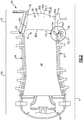
- Figure 2 illustrates a view taken through selected portions of the combustor 56 and high pressure turbine 54 of the engine 20.
- the combustor 56 is an annular combustor that extends around the engine central axis A, although it is contemplated that the examples herein are also applicable to can type combustors.
- the combustor 56 includes a radially inner shell or combustor wall 62 and a radially outer shell or combustor wall 64.
- the walls 62/64 define an annular combustor chamber 66 there between.
- the combustor 56 includes one or more injectors 68 at a forward end of the combustor 56, and an exit region 70 at the aft end of the combustor 56.
- the combustor walls 62/64 each include a lip 65 at the axially trailing end thereof.
- the high pressure turbine 54 includes a circumferential row of turbine vanes 72 adjacent the exit region 70.
- Each vane 72 includes an inner or first platform 74, an outer or second platform 76, and an airfoil section 78 that spans in a radial direction between the first and second platforms 74/76.
- a radial view of a portion of the row of turbine vanes 72 is also shown in Figure 3 . Terms such as “radially,” “axially,” “circumferentially,” or variations thereof are used herein to designate directionality with respect to the engine central axis A.
- the airfoil section 78 includes an airfoil outer wall 80 that delimits the profile of the airfoil section 78.
- the outer wall 80 defines a leading end 80a, a trailing end 80b, and first and second sides 80c/80d that join the leading and trailing ends 80a/80b.
- the first and second sides 80c/80d span in the radial direction between first and second ends 80e/80f that are attached, respectively, to the first and second platforms 74/76.
- the first side 80c is a suction side and the second side 80d is a pressure side.
- the first platform 74 ( Figure 3 ) defines forward and trailing edges 74a/74b and first and second circumferential side edges 74c/74d that join the forward and trailing edges 74a/74b.
- first and second circumferential side edges 74c/74d mate with or bear against the respective second and first circumferential side edges 74c/74d of the adjacent vanes 72.
- the second platform 76 defines forward and trailing edges and first and second circumferential side edges that join the forward and trailing edges.
- the first and second circumferential side edges also mate with or bear against the respective second and first circumferential side edges of the adjacent vanes 72.
- the examples herein below may be directed to the first platform 74. However, it is to be understood that the examples are also applicable to the second platform 76.
- Figure 4 illustrates a magnified view of the exit region 70 of the combustor 56 at the forward edge 74a of the vane 72
- Figure 5 illustrates a sectioned view of the same area.
- the forward edge 74a is adjacent the lip 65 of the combustor wall 62.
- the vane 72 is shown in a seated position. In the seated position, a bearing surface 75 on the forward edge 74a of the platform 74 abuts the lip 65 of the combustor wall 62. The abutment between the lip 65 and the bearing surface 75 provides a primary seal across the interface between the platform 74 and the combustor wall 62 to prevent the escape of combustion gases from the core flow path.
- the lip 65 defines a first annular slot 82 and the forward edges 74a of the platforms 74 of the vanes 72 collectively define a second annular slot 84.
- the first and second annular slots 82/84 together define an annular seal slot 86.
- An annular feather seal 88 is entrapped in the annular seal slot 86 between the combustor wall 62 and the platform 74.
- the platform 74 can move axially away from the lip 65, thereby opening a gap through which combustion gases can escape.
- the annular feather seal 88 serves as a secondary seal across the interface between the platform 74 and the combustor wall 62 to prevent the escape of combustion gases from the core gaspath.
- the vanes 72 have rotational play about their radial axes A1 under aerodynamic loads.
- the vanes 72 are generally statically mounted, due to tolerances in manufacturing and assembly, the vanes 72 can shift somewhat from their proper design positions in which the bearing surfaces 75 are seated against the lip 65.
- Flow of combustion gases from the combustor 56 impinges against the second side 80d of the airfoil section 78, particularly toward the trailing end 80b, thereby generating a rotational force about the axis A1.
- the rotational forces can cause the vanes 72 to rotate from their design positions.
- the divergent gap 92 presents an unusual sealing challenge because the vanes 72 may dynamically move between the seated and unseated positions during engine operation and the forward edges 74a of the platforms 74 and the lip 65 are non-parallel when in the unseated position.
- seals that cannot accommodate dynamic movement or seals that rely on parallel sides may not provide a desired level of sealing.
- the annular feather seal 88 is able to address both the dynamic movement and the non-parallel nature of the divergent gap 92.
- the configuration of the feather seal 88 and the seal slot 86 facilitate dynamic sealing of the divergent gap 92.
- the seal slot 86 defines a slot radial thickness t1 and the feather seal 88 defines a seal radial thickness t2, where t2 is less than t1.
- the seal slot 86 also defines a slot axial width w1 and the feather seal 88 defines a seal axial width w2, where w2 is less than w1. That is, the feather seal 88 is smaller in cross-section than the seal slot 86. This permits the feather seal 88 to shift dynamically within the seal slot 86 to accommodate shifts in the position of the vanes 72.
- the seal axial width w2 is larger (i.e., wider) than the divergent gap 92, to maintain sealing when the vane 72 is in the unseated state.
- the play in the vanes 72 may be determined or estimated during engine design to determine or estimate the maximum size of the divergent gap 92.
- the seal axial width w2 is then selected to be larger than the maximum size in order to ensure sealing entirely along the divergent gap 92.
- the first and second annular slots 82/84 that define the annular seal slot 86 are also configured to bias the feather seal 88 to a sealed position.
- the first slot 82 is defined by radially inner and outer walls 82a/82b of the combustor wall 62
- the second slot 84 is defined by radially inner and outer walls 84a/84b of the platform 74.
- the outer wall 82b and the outer wall 84b abut (at bearing surface 75 and lip 65).
- the inner wall 82a and the inner wall 84a are axially spaced apart such that there is a gap 94 there between.
- There is a high pressure region "P" ( Figure 4 ) radially inwards of the combustor wall 62 and the platform 74.
- the pressure in the high pressure region is greater than the pressure in the core gaspath.
- the high pressure communicates through the gap 94 into the seal slot 86 to bias the feather seal 88 radially outwards, against the outer walls 82b/84b, thereby maintaining the feather seal 88 in a sealed position.
- At least one of the inner wall 82a or the inner wall 84a may be scalloped.
- Figure 6 shows an example of the inner wall 82a, although it is to be understood that the example is also applicable to the inner wall 84a.
- the inner wall 82a includes tabs 96 and axial slots 98 that are circumferentially between the tabs 96 to provide a scalloped configuration.
- the axial slots 98 provide additional area for communication of the high pressure into the seal slot 86 to bias the feather seal 88 radially outwards.
- the feather seal 88 is also configured to dynamically adapt in diametric size to maintain sealing.
- Figure 7 shows an isolated axial view of the feather seal 88.
- the feather seal is a split ring.
- the split ring has first and second ends 88a/88b that are overlapping.
- the ends 88a/88b are thus free to move relative to one another.
- the split ring can thereby readily expand and contract in diameter.
- the split ring may thermally expand and contract with thermal transients in the engine 20. If constrained, as an endless ring, such expansion or contraction may cause a seal to unseat from its sealing position.
- the ends 88a/88b can move, the feather seal 88 can readily expand and contract and thereby maintain a sealing position against the radially outer walls 82b/84b in the seal slot 86 under various thermal conditions.
Landscapes
- Engineering & Computer Science (AREA)
- Mechanical Engineering (AREA)
- General Engineering & Computer Science (AREA)
- Chemical & Material Sciences (AREA)
- Combustion & Propulsion (AREA)
- Turbine Rotor Nozzle Sealing (AREA)
Abstract
Description
- A gas turbine engine typically includes a fan section, a compressor section, a combustor section and a turbine section. Air entering the compressor section is compressed and delivered into the combustion section where it is mixed with fuel and ignited to generate a high-speed exhaust gas flow. The high-speed exhaust gas flow expands through the turbine section to drive the compressor and the fan section. The compressor section typically includes low and high pressure compressors, and the turbine section includes low and high pressure turbines.
- The high pressure turbine drives the high pressure compressor through an outer shaft to form a high spool, and the low pressure turbine drives the low pressure compressor through an inner shaft to form a low spool. The fan section may also be driven by the low inner shaft. A direct drive gas turbine engine includes a fan section driven by the low spool such that the low pressure compressor, low pressure turbine and fan section rotate at a common speed in a common direction.
- A gas turbine engine according to a first aspect of the present disclosure includes a combustor that has a combustor wall and a combustion chamber. The combustor wall has a lip at an exit region of the combustion chamber. There is a circumferential row of vanes adjacent the exit region. Each vane includes a platform and an airfoil section extending from the platform. The platform defines forward and trailing edges and first and second circumferential side edges joining the forward and trailing edges. The forward edge is adjacent the lip of the combustor wall. The lip defines a first annular slot and the forward edges collectively defining a second annular slot. The first and second annular slots together define an annular seal slot. An annular feather seal is entrapped in the annular seal slot between the combustor wall and the platform.
- In an embodiment of the foregoing embodiment, the platform is radially inwards of the airfoil section.
- In a further embodiment of any of the foregoing embodiments, the lip of the combustor abuts the leading edge of the platform.
- In a further embodiment of any of the foregoing embodiments, the annular feather seal is a split ring.
- In a further embodiment of any of the foregoing embodiments, the split ring has overlapping ends.
- In a further embodiment of any of the foregoing embodiments, the first annular slot is defined by radially inner and outer walls of the combustor wall and the second annular slot is defined by radially inner and outer walls of the platform.
- In a further embodiment of any of the foregoing embodiments, the radially outer wall of the first annular slot and the radially outer wall of the second annular slot abut, and the radially inner wall of the first annular slot and the radially inner wall of the second slot are axially spaced apart such that there is a gap there between.
- In a further embodiment of any of the foregoing embodiments, at least one of the radially inner wall of the first annular slot or the radially inner wall of the second annular slot is scalloped.
- In a further embodiment of any of the foregoing embodiments, the seal slot is radially thicker than the annular feather seal.
- A gas turbine engine according to a second aspect of the present disclosure includes a combustor that has a combustor wall and a combustion chamber. The combustor wall has a lip at an exit region of the combustion chamber. There is a vane adjacent the exit region that has a platform and an airfoil section extending along a radial axis from the platform. The platform defines forward and trailing edges and first and second circumferential side edges joining the forward and trailing edges. The vane has rotational play about the radial axis under aerodynamic loads such that the vane moves relative to the combustor between a seated state in which the forward edge abuts the lip of the combustor wall and an unseated state in which there is a divergent gap between the forward edge and the lip of the combustor. The lip defines a first slot that extends circumferentially and the forward edge defines a second slot that extends circumferentially. The first and second slots together define a seal slot. An annular feather seal extends in the seal slot. The annular feather seal is wider than the divergent gap to maintain sealing when in the vane is in the unseated state.
- In an embodiment of the foregoing embodiment, the first side of the airfoil section is a suction side, the second side of the airfoil section is a pressure side, the second circumferential side of the platform is located to the second side of the airfoil section, and the divergent gap diverges toward the second circumferential side.
- In a further embodiment of any of the foregoing embodiments, the annular feather seal is a split ring.
- In a further embodiment of any of the foregoing embodiments, the split ring has overlapping ends.
- In a further embodiment of any of the foregoing embodiments, the first slot is defined by first radially inner and outer walls of the combustor wall and the second slot is defined by radially inner and outer walls of the platform.
- In a further embodiment of any of the foregoing embodiments, at least one of the radially inner wall of the first annular slot or the radially inner wall of the second annular slot is scalloped.
- In a further embodiment of any of the foregoing embodiments, the seal slot is radially thicker than the annular feather seal.
- An airfoil according to a third aspect of the present disclosure includes a vane that has a platform and an airfoil section that extends from the platform. The platform defines forward and trailing edges and first and second circumferential side edges that join the forward and trailing edges. The forward edge includes a bearing surface for abutting a lip of a combustor wall. The forward edge defines a slot arc segment for receiving a portion of an annular feather seal.
- In an embodiment of the foregoing embodiment, the platform is radially inwards of the airfoil section.
- In a further embodiment of any of the foregoing embodiments, the slot arc segment is defined by radially inner and outer walls, and the radially inner wall is scalloped.
- The various features and advantages of the present disclosure will become apparent to those skilled in the art from the following detailed description. The drawings that accompany the detailed description can be briefly described as follows.
-
Figure 1 illustrates an example gas turbine engine. -
Figure 2 illustrates portions of the combustor and turbine section of the engine ofFigure 1 . -
Figure 3 illustrates a radial view of turbine vanes in the turbine section. -
Figure 4 illustrates a magnified view of the interface between the combustor and the turbine vanes. -
Figure 5 illustrates a sectioned view of the interface between the combustor and the turbine vanes. -
Figure 6 illustrates a scalloped lip of the combustor. -
Figure 7 illustrates an isolated view of a feather seal split ring. -
Figure 1 schematically illustrates agas turbine engine 20. Thegas turbine engine 20 is disclosed herein as a two-spool turbofan that generally incorporates afan section 22, acompressor section 24, acombustor section 26 and aturbine section 28. Thefan section 22 drives air along a bypass flow path B in a bypass duct defined within anacelle 15, and also drives air along a core flow path C for compression and communication into thecombustor section 26 then expansion through theturbine section 28. Although depicted as a two-spool turbofan gas turbine engine in the disclosed non-limiting embodiment, it should be understood that the concepts described herein are not limited to use with two-spool turbofans as the teachings may be applied to other types of turbine engines including three-spool architectures. - The
exemplary engine 20 generally includes alow speed spool 30 and a high speed spool 32 mounted for rotation about an engine central longitudinal axis A relative to an enginestatic structure 36 viaseveral bearing systems 38. It should be understood thatvarious bearing systems 38 at various locations may alternatively or additionally be provided, and the location ofbearing systems 38 may be varied as appropriate to the application. - The
low speed spool 30 generally includes aninner shaft 40 that interconnects, a first (or low)pressure compressor 44 and a first (or low)pressure turbine 46. Theinner shaft 40 is connected to thefan 42 through a speed change mechanism, which in exemplarygas turbine engine 20 is illustrated as a gearedarchitecture 48 to drive afan 42 at a lower speed than thelow speed spool 30. The high speed spool 32 includes anouter shaft 50 that interconnects a second (or high) pressure compressor 52 and a second (or high)pressure turbine 54. Acombustor 56 is arranged inexemplary gas turbine 20 between the high pressure compressor 52 and thehigh pressure turbine 54. Amid-turbine frame 57 of the enginestatic structure 36 may be arranged generally between thehigh pressure turbine 54 and thelow pressure turbine 46. Themid-turbine frame 57 furthersupports bearing systems 38 in theturbine section 28. Theinner shaft 40 and theouter shaft 50 are concentric and rotate via bearingsystems 38 about the engine central longitudinal axis A which is collinear with their longitudinal axes. - The core airflow is compressed by the
low pressure compressor 44 then the high pressure compressor 52, mixed and burned with fuel in thecombustor 56, then expanded over thehigh pressure turbine 54 andlow pressure turbine 46. Themid-turbine frame 57 includesairfoils 59 which are in the core airflow path C. Theturbines low speed spool 30 and high speed spool 32 in response to the expansion. It will be appreciated that each of the positions of thefan section 22,compressor section 24,combustor section 26,turbine section 28, and fandrive gear system 48 may be varied. For example,gear system 48 may be located aft of the low pressure compressor, or aft of thecombustor section 26 or even aft ofturbine section 28, andfan 42 may be positioned forward or aft of the location ofgear system 48. - The
engine 20 in one example is a high-bypass geared aircraft engine. In a further example, theengine 20 bypass ratio is greater than about six, with an example embodiment being greater than about ten, the gearedarchitecture 48 is an epicyclic gear train, such as a planetary gear system or other gear system, with a gear reduction ratio of greater than about 2.3 and thelow pressure turbine 46 has a pressure ratio that is greater than about five. In one disclosed embodiment, theengine 20 bypass ratio is greater than about ten, the fan diameter is significantly larger than that of thelow pressure compressor 44, and thelow pressure turbine 46 has a pressure ratio that is greater than about five.Low pressure turbine 46 pressure ratio is pressure measured prior to inlet oflow pressure turbine 46 as related to the pressure at the outlet of thelow pressure turbine 46 prior to an exhaust nozzle. The gearedarchitecture 48 may be an epicycle gear train, such as a planetary gear system or other gear system, with a gear reduction ratio of greater than about 2.3:1 and less than about 5:1. It should be understood, however, that the above parameters are only exemplary of one embodiment of a geared architecture engine and that the present invention is applicable to other gas turbine engines including direct drive turbofans. - A significant amount of thrust is provided by the bypass flow B due to the high bypass ratio. The
fan section 22 of theengine 20 is designed for a particular flight condition -- typically cruise at about 0.8 Mach and about 35,000 feet (10,668 meters). The flight condition of 0.8 Mach and 35,000 ft (10,668 meters), with the engine at its best fuel consumption - also known as "bucket cruise Thrust Specific Fuel Consumption ('TSFC')" - is the industry standard parameter of lbm of fuel being burned divided by lbf of thrust the engine produces at that minimum point. "Low fan pressure ratio" is the pressure ratio across the fan blade alone, without a Fan Exit Guide Vane ("FEGV") system. The low fan pressure ratio as disclosed herein according to one non-limiting embodiment is less than about 1.45. "Low corrected fan tip speed" is the actual fan tip speed in ft/sec divided by an industry standard temperature correction of [(Tram °R) / (518.7 °R)]^0.5 (where °R = K x 9/5). The "Low corrected fan tip speed" as disclosed herein according to one non-limiting embodiment is less than about 1150 ft / second (350.5 meters/second). -
Figure 2 illustrates a view taken through selected portions of thecombustor 56 andhigh pressure turbine 54 of theengine 20. In this example, thecombustor 56 is an annular combustor that extends around the engine central axis A, although it is contemplated that the examples herein are also applicable to can type combustors. Thecombustor 56 includes a radially inner shell orcombustor wall 62 and a radially outer shell orcombustor wall 64. Thewalls 62/64 define anannular combustor chamber 66 there between. Thecombustor 56 includes one ormore injectors 68 at a forward end of thecombustor 56, and anexit region 70 at the aft end of thecombustor 56. Thecombustor walls 62/64 each include alip 65 at the axially trailing end thereof. - The
high pressure turbine 54 includes a circumferential row ofturbine vanes 72 adjacent theexit region 70. Eachvane 72 includes an inner orfirst platform 74, an outer orsecond platform 76, and anairfoil section 78 that spans in a radial direction between the first andsecond platforms 74/76. A radial view of a portion of the row ofturbine vanes 72 is also shown inFigure 3 . Terms such as "radially," "axially," "circumferentially," or variations thereof are used herein to designate directionality with respect to the engine central axis A. - The
airfoil section 78 includes an airfoilouter wall 80 that delimits the profile of theairfoil section 78. Theouter wall 80 defines aleading end 80a, a trailingend 80b, and first andsecond sides 80c/80d that join the leading and trailing ends 80a/80b. The first andsecond sides 80c/80d span in the radial direction between first andsecond ends 80e/80f that are attached, respectively, to the first andsecond platforms 74/76. In this example, thefirst side 80c is a suction side and thesecond side 80d is a pressure side. - The first platform 74 (
Figure 3 ) defines forward and trailingedges 74a/74b and first and second circumferential side edges 74c/74d that join the forward and trailingedges 74a/74b. Generally, the first and second circumferential side edges 74c/74d mate with or bear against the respective second and first circumferential side edges 74c/74d of theadjacent vanes 72. Likewise, thesecond platform 76 defines forward and trailing edges and first and second circumferential side edges that join the forward and trailing edges. The first and second circumferential side edges also mate with or bear against the respective second and first circumferential side edges of theadjacent vanes 72. The examples herein below may be directed to thefirst platform 74. However, it is to be understood that the examples are also applicable to thesecond platform 76. -
Figure 4 illustrates a magnified view of theexit region 70 of thecombustor 56 at theforward edge 74a of thevane 72, andFigure 5 illustrates a sectioned view of the same area. Theforward edge 74a is adjacent thelip 65 of thecombustor wall 62. InFigures 4 and 5 , thevane 72 is shown in a seated position. In the seated position, a bearingsurface 75 on theforward edge 74a of theplatform 74 abuts thelip 65 of thecombustor wall 62. The abutment between thelip 65 and the bearingsurface 75 provides a primary seal across the interface between theplatform 74 and thecombustor wall 62 to prevent the escape of combustion gases from the core flow path. - The
lip 65 defines a firstannular slot 82 and theforward edges 74a of theplatforms 74 of thevanes 72 collectively define a secondannular slot 84. The first and secondannular slots 82/84 together define anannular seal slot 86. Anannular feather seal 88 is entrapped in theannular seal slot 86 between thecombustor wall 62 and theplatform 74. As will be described further below, theplatform 74 can move axially away from thelip 65, thereby opening a gap through which combustion gases can escape. In this regard, theannular feather seal 88 serves as a secondary seal across the interface between theplatform 74 and thecombustor wall 62 to prevent the escape of combustion gases from the core gaspath. - As shown in
Figure 3 and represented at 90, thevanes 72 have rotational play about their radial axes A1 under aerodynamic loads. For instance, although thevanes 72 are generally statically mounted, due to tolerances in manufacturing and assembly, thevanes 72 can shift somewhat from their proper design positions in which the bearing surfaces 75 are seated against thelip 65. Flow of combustion gases from thecombustor 56 impinges against thesecond side 80d of theairfoil section 78, particularly toward the trailingend 80b, thereby generating a rotational force about the axis A1. In combination with the play in the position of thevanes 72, the rotational forces can cause thevanes 72 to rotate from their design positions. The rotation tends to shift one side of thevanes 72 in an axially aft direction, unseating the bearingsurface 75 from thelip 65. In the unseated position there is thus adivergent gap 92 across the interface between theplatform 74 and thecombustor wall 62 through which combustion gases can escape. That is, one corner of theplatform 74 at theforward edge 74a remains in contact with, or at least in close proximity to, thelip 65, while the opposite corner of theplatform 74 at theforward edge 74a shifts axially aftwards. - In particular, the
divergent gap 92 presents an unusual sealing challenge because thevanes 72 may dynamically move between the seated and unseated positions during engine operation and theforward edges 74a of theplatforms 74 and thelip 65 are non-parallel when in the unseated position. Thus, seals that cannot accommodate dynamic movement or seals that rely on parallel sides may not provide a desired level of sealing. In this regard, theannular feather seal 88 is able to address both the dynamic movement and the non-parallel nature of thedivergent gap 92. - For example, the configuration of the
feather seal 88 and theseal slot 86 facilitate dynamic sealing of thedivergent gap 92. In one example, theseal slot 86 defines a slot radial thickness t1 and thefeather seal 88 defines a seal radial thickness t2, where t2 is less than t1. Theseal slot 86 also defines a slot axial width w1 and thefeather seal 88 defines a seal axial width w2, where w2 is less than w1. That is, thefeather seal 88 is smaller in cross-section than theseal slot 86. This permits thefeather seal 88 to shift dynamically within theseal slot 86 to accommodate shifts in the position of thevanes 72. Additionally, the seal axial width w2 is larger (i.e., wider) than thedivergent gap 92, to maintain sealing when thevane 72 is in the unseated state. For instance, the play in thevanes 72 may be determined or estimated during engine design to determine or estimate the maximum size of thedivergent gap 92. The seal axial width w2 is then selected to be larger than the maximum size in order to ensure sealing entirely along thedivergent gap 92. - The first and second
annular slots 82/84 that define theannular seal slot 86 are also configured to bias thefeather seal 88 to a sealed position. For example, thefirst slot 82 is defined by radially inner andouter walls 82a/82b of thecombustor wall 62, and thesecond slot 84 is defined by radially inner andouter walls 84a/84b of theplatform 74. Theouter wall 82b and theouter wall 84b abut (at bearingsurface 75 and lip 65). Theinner wall 82a and theinner wall 84a are axially spaced apart such that there is agap 94 there between. There is a high pressure region "P" (Figure 4 ) radially inwards of thecombustor wall 62 and theplatform 74. The pressure in the high pressure region is greater than the pressure in the core gaspath. The high pressure communicates through thegap 94 into theseal slot 86 to bias thefeather seal 88 radially outwards, against theouter walls 82b/84b, thereby maintaining thefeather seal 88 in a sealed position. - To further permit communication of the high pressure in addition to the
gap 94, and also reduce weight, at least one of theinner wall 82a or theinner wall 84a may be scalloped.Figure 6 shows an example of theinner wall 82a, although it is to be understood that the example is also applicable to theinner wall 84a. As shown, theinner wall 82a includestabs 96 andaxial slots 98 that are circumferentially between thetabs 96 to provide a scalloped configuration. Theaxial slots 98 provide additional area for communication of the high pressure into theseal slot 86 to bias thefeather seal 88 radially outwards. - The
feather seal 88 is also configured to dynamically adapt in diametric size to maintain sealing.Figure 7 shows an isolated axial view of thefeather seal 88. In this example, the feather seal is a split ring. The split ring has first andsecond ends 88a/88b that are overlapping. The ends 88a/88b are thus free to move relative to one another. The split ring can thereby readily expand and contract in diameter. For instance, the split ring may thermally expand and contract with thermal transients in theengine 20. If constrained, as an endless ring, such expansion or contraction may cause a seal to unseat from its sealing position. However, because the ends 88a/88b can move, thefeather seal 88 can readily expand and contract and thereby maintain a sealing position against the radiallyouter walls 82b/84b in theseal slot 86 under various thermal conditions. - Although a combination of features is shown in the illustrated examples, not all of them need to be combined to realize the benefits of various embodiments of this disclosure. In other words, a system designed according to an embodiment of this disclosure will not necessarily include all of the features shown in any one of the Figures or all of the portions schematically shown in the Figures. Moreover, selected features of one example embodiment may be combined with selected features of other example embodiments.
- The preceding description is exemplary rather than limiting in nature. Variations and modifications to the disclosed examples may become apparent to those skilled in the art that do not necessarily depart from this disclosure. The scope of legal protection given to this disclosure can only be determined by studying the following claims.
Claims (15)
- A gas turbine engine (20) comprising:a combustor (56) disposed about an engine central axis (A) and including a combustor wall (62, 64) and a combustion chamber (66), the combustor wall (62, 64) having a lip (65) at an exit region (70) of the combustion chamber (66);a circumferential row of vanes (72) adjacent the exit region (70), each said vane (72) including a platform (74, 76) and an airfoil section (78) extending from the platform (74, 76), the platform (74, 76) defining forward and trailing edges (74a, 74b) and first and second circumferential side edges (74c, 74d) joining the forward and trailing edges (74a, 74b), the forward edge (74a) being adjacent the lip (65) of the combustor wall (62, 64),the lip (65) defining a first annular slot (82) and the forward edges (74a) collectively defining a second annular slot (84), the first and second annular slots (82, 84) together defining an annular seal slot (86); andan annular feather seal (88) entrapped in the annular seal slot (86) between the combustor wall (62, 64) and the platform (74, 76).
- The gas turbine engine as recited in claim 1, wherein the platform (74, 76) is radially inwards of the airfoil section (78).
- The gas turbine engine as recited in claim 1 or 2, wherein the lip (65) of the combustor (56) abuts the forward edge (74a) of the platform (74, 76).
- The gas turbine engine as recited in any of claims 1 to 3, wherein the first annular slot (82) is defined by radially inner and outer walls (82a, 82b) of the combustor wall (62, 64) and the second annular slot (84) is defined by radially inner and outer walls (84a, 84b) of the platform (74, 76).
- The gas turbine engine as recited in claim 4, wherein the radially outer wall (82b) of the first annular slot (82) and the radially outer wall (84b) of the second annular slot (84) abut, and the radially inner wall (82a) of the first annular slot (82) and the radially inner wall (84a) of the second annular slot (84) are axially spaced apart such that there is a gap (94) therebetween.
- The gas turbine engine as recited in claim 4 or 5, wherein at least one of the radially inner wall (82a) of the first annular slot (82) or the radially inner wall (84a) of the second annular slot (84) is scalloped.
- A gas turbine engine (20) comprising:a combustor (56) disposed about an engine central axis (A) and including a combustor wall (62, 64) and a combustion chamber (66), the combustor wall (62, 64) having a lip (65) at an exit region (70) of the combustion chamber (66);a vane (72) adjacent the exit region (70), the vane (72) including a platform (74, 76) and an airfoil section (78) extending along a radial axis from the platform (74, 76), the platform (74, 76) defining forward and trailing edges (74a, 74b) and first and second circumferential side edges (74c, 74d) joining the forward and trailing edges (74a, 74b),the vane (72) having rotational play about the radial axis under aerodynamic loads such that the vane (72) moves relative to the combustor (56) between a seated state in which the forward edge (74a) abuts the lip (65) of the combustor wall (62, 64) and an unseated state in which there is a divergent gap (92) between the forward edge (74a) and the lip (65) of the combustor (56),the lip (65) defining a first slot (82) extending circumferentially and the forward edge (74a) defining a second slot (84) extending circumferentially, the first and second slots (82, 84) together defining a seal slot (86); andan annular feather seal (88) extending in the seal slot (86), the annular feather seal (88) being wider than the divergent gap (92) to maintain sealing when in the vane (72) is in the unseated state.
- The gas turbine engine as recited in claim 7, wherein a first side (80c) of the airfoil section (78) is a suction side, a second side (80d) of the airfoil section (78) is a pressure side, the second circumferential side edge (74d) of the platform (74, 76) is located to the second side (80d) of the airfoil section (78), and the divergent gap (92) diverges toward the second circumferential side edge (76d).
- The gas turbine engine as recited in claim 7 or 8, wherein the first slot (82) is defined by first radially inner and outer walls (82a, 82b) of the combustor wall (62, 64) and the second slot (84) is defined by radially inner and outer walls (84a, 84b) of the platform (74, 76), and optionally at least one of the radially inner wall (82a) of the first slot (82) or the radially inner wall (84a) of the second slot (84) is scalloped.
- The gas turbine engine as recited in any preceding claim, wherein the annular feather seal (88) is a split ring.
- The gas turbine engine as recited in claim 10, wherein the split ring has overlapping ends (88a, 88b).
- The gas turbine engine as recited in any preceding claim, wherein the seal slot (86) is radially thicker than the annular feather seal (88).
- An airfoil comprising:a vane (72) including a platform (74, 76) and an airfoil section (78) extending from the platform (74, 76), the platform (74, 76) defining forward and trailing edges (74a, 74b) and first and second circumferential side edges (74c, 74d) joining the forward and trailing edges (74a, 74b),the forward edge (74a) including a bearing surface (75) for abutting a lip (65) of a combustor wall (62, 64), andthe forward edge (74a) defining a slot arc segment for receiving a portion of an annular feather seal (88).
- The airfoil as recited in claim 13, wherein the platform (74, 76) is radially inwards of the airfoil section (78).
- The airfoil as recited in claim 13 and 14, wherein the slot arc segment is defined by radially inner and outer walls (84a, 84b), and the radially inner wall (84a) is scalloped.
Applications Claiming Priority (1)
| Application Number | Priority Date | Filing Date | Title |
|---|---|---|---|
| US16/195,925 US20200157959A1 (en) | 2018-11-20 | 2018-11-20 | Combustor-vane interface feather seal |
Publications (1)
| Publication Number | Publication Date |
|---|---|
| EP3656985A1 true EP3656985A1 (en) | 2020-05-27 |
Family
ID=68621193
Family Applications (1)
| Application Number | Title | Priority Date | Filing Date |
|---|---|---|---|
| EP19210456.0A Pending EP3656985A1 (en) | 2018-11-20 | 2019-11-20 | Combustor-vane interface feather seal |
Country Status (2)
| Country | Link |
|---|---|
| US (1) | US20200157959A1 (en) |
| EP (1) | EP3656985A1 (en) |
Citations (4)
| Publication number | Priority date | Publication date | Assignee | Title |
|---|---|---|---|---|
| US4465284A (en) * | 1983-09-19 | 1984-08-14 | General Electric Company | Scalloped cooling of gas turbine transition piece frame |
| WO2000012870A1 (en) * | 1998-09-02 | 2000-03-09 | General Electric Company | C-shaped ring seal |
| EP2660428A1 (en) * | 2012-04-30 | 2013-11-06 | General Electric Company | Turbine system comprising a transition duct with a flexible seal |
| EP3372792A1 (en) * | 2017-03-07 | 2018-09-12 | General Electric Company | Gas turbine transition piece seal system |
-
2018
- 2018-11-20 US US16/195,925 patent/US20200157959A1/en active Pending
-
2019
- 2019-11-20 EP EP19210456.0A patent/EP3656985A1/en active Pending
Patent Citations (4)
| Publication number | Priority date | Publication date | Assignee | Title |
|---|---|---|---|---|
| US4465284A (en) * | 1983-09-19 | 1984-08-14 | General Electric Company | Scalloped cooling of gas turbine transition piece frame |
| WO2000012870A1 (en) * | 1998-09-02 | 2000-03-09 | General Electric Company | C-shaped ring seal |
| EP2660428A1 (en) * | 2012-04-30 | 2013-11-06 | General Electric Company | Turbine system comprising a transition duct with a flexible seal |
| EP3372792A1 (en) * | 2017-03-07 | 2018-09-12 | General Electric Company | Gas turbine transition piece seal system |
Also Published As
| Publication number | Publication date |
|---|---|
| US20200157959A1 (en) | 2020-05-21 |
Similar Documents
| Publication | Publication Date | Title |
|---|---|---|
| US11421558B2 (en) | Gas turbine engine component | |
| EP3112606B1 (en) | A seal for a gas turbine engine | |
| EP3296519B1 (en) | Flowpath component for a gas turbine engine including a chordal seal | |
| EP3219924A1 (en) | Turbine engine blade outer air seal with load transmitting cover plate | |
| EP3012492A1 (en) | Sliding seal | |
| US20160169004A1 (en) | Cooling passages for gas turbine engine component | |
| EP3056685B1 (en) | Stator vane with platform having sloped face | |
| EP3219935B1 (en) | Turbine engine blade outer air seal with load-transmitting carriage | |
| EP3543469B1 (en) | Blade outer air seal assembly with feather seal | |
| EP3228830A1 (en) | Blade outer air seal with centrally mounted seal arc segments | |
| US20210148247A1 (en) | Blade outer air seal including cooling trench | |
| US10890079B2 (en) | Gas turbine engine arc segments with arced walls | |
| EP3043030A1 (en) | Anti-rotation vane | |
| EP3825518A1 (en) | Vane retention assembly | |
| EP3656985A1 (en) | Combustor-vane interface feather seal | |
| EP3498978B1 (en) | Gas turbine engine vane with attachment hook | |
| EP3786417A1 (en) | Axial retention geometry for a turbine engine blade outer air seal | |
| EP3734018B1 (en) | Seal for a gas turbine engine component and corresponding method | |
| US11401830B2 (en) | Geometry for a turbine engine blade outer air seal | |
| EP3495621B1 (en) | Support ring for a gas turbine engine | |
| EP3708773A2 (en) | Seal for a rotor stack, corresponding gas turbine engine and method of sealing a shaft relatively to a rotor disk | |
| EP3056686B1 (en) | Rotor with axial arm having protruding ramp |
Legal Events
| Date | Code | Title | Description |
|---|---|---|---|
| PUAI | Public reference made under article 153(3) epc to a published international application that has entered the european phase |
Free format text: ORIGINAL CODE: 0009012 |
|
| STAA | Information on the status of an ep patent application or granted ep patent |
Free format text: STATUS: THE APPLICATION HAS BEEN PUBLISHED |
|
| AK | Designated contracting states |
Kind code of ref document: A1 Designated state(s): AL AT BE BG CH CY CZ DE DK EE ES FI FR GB GR HR HU IE IS IT LI LT LU LV MC MK MT NL NO PL PT RO RS SE SI SK SM TR |
|
| AX | Request for extension of the european patent |
Extension state: BA ME |
|
| STAA | Information on the status of an ep patent application or granted ep patent |
Free format text: STATUS: REQUEST FOR EXAMINATION WAS MADE |
|
| 17P | Request for examination filed |
Effective date: 20201127 |
|
| RBV | Designated contracting states (corrected) |
Designated state(s): AL AT BE BG CH CY CZ DE DK EE ES FI FR GB GR HR HU IE IS IT LI LT LU LV MC MK MT NL NO PL PT RO RS SE SI SK SM TR |
|
| RAP1 | Party data changed (applicant data changed or rights of an application transferred) |
Owner name: RAYTHEON TECHNOLOGIES CORPORATION |
|
| STAA | Information on the status of an ep patent application or granted ep patent |
Free format text: STATUS: EXAMINATION IS IN PROGRESS |
|
| 17Q | First examination report despatched |
Effective date: 20221205 |
|
| RAP3 | Party data changed (applicant data changed or rights of an application transferred) |
Owner name: RTX CORPORATION |