EP3655920B1 - Method and device for analysing image sections for a correspondence calculation - Google Patents
Method and device for analysing image sections for a correspondence calculation Download PDFInfo
- Publication number
- EP3655920B1 EP3655920B1 EP18731048.7A EP18731048A EP3655920B1 EP 3655920 B1 EP3655920 B1 EP 3655920B1 EP 18731048 A EP18731048 A EP 18731048A EP 3655920 B1 EP3655920 B1 EP 3655920B1
- Authority
- EP
- European Patent Office
- Prior art keywords
- image
- noise
- image sensor
- signal
- resulting
- Prior art date
- Legal status (The legal status is an assumption and is not a legal conclusion. Google has not performed a legal analysis and makes no representation as to the accuracy of the status listed.)
- Active
Links
- 238000000034 method Methods 0.000 title claims description 28
- 238000004364 calculation method Methods 0.000 title description 3
- 238000011156 evaluation Methods 0.000 claims description 112
- 230000006641 stabilisation Effects 0.000 claims description 14
- 238000011105 stabilization Methods 0.000 claims description 14
- 238000007906 compression Methods 0.000 claims description 9
- 230000006835 compression Effects 0.000 claims description 9
- 230000002123 temporal effect Effects 0.000 claims description 5
- 238000001914 filtration Methods 0.000 claims description 4
- 230000015572 biosynthetic process Effects 0.000 description 26
- 238000012545 processing Methods 0.000 description 16
- 238000013507 mapping Methods 0.000 description 15
- 230000033001 locomotion Effects 0.000 description 13
- 238000009499 grossing Methods 0.000 description 7
- 230000008569 process Effects 0.000 description 5
- 239000010426 asphalt Substances 0.000 description 4
- 230000005540 biological transmission Effects 0.000 description 4
- 238000010586 diagram Methods 0.000 description 3
- 230000003287 optical effect Effects 0.000 description 3
- 238000013139 quantization Methods 0.000 description 3
- 230000006978 adaptation Effects 0.000 description 2
- 230000003321 amplification Effects 0.000 description 2
- 230000001419 dependent effect Effects 0.000 description 2
- 238000005259 measurement Methods 0.000 description 2
- 238000003199 nucleic acid amplification method Methods 0.000 description 2
- 238000003860 storage Methods 0.000 description 2
- 239000000654 additive Substances 0.000 description 1
- 230000000996 additive effect Effects 0.000 description 1
- 238000013459 approach Methods 0.000 description 1
- 230000008901 benefit Effects 0.000 description 1
- 230000003139 buffering effect Effects 0.000 description 1
- 230000008859 change Effects 0.000 description 1
- 238000013144 data compression Methods 0.000 description 1
- 238000009826 distribution Methods 0.000 description 1
- 230000000694 effects Effects 0.000 description 1
- 238000005516 engineering process Methods 0.000 description 1
- 230000007613 environmental effect Effects 0.000 description 1
- 230000002349 favourable effect Effects 0.000 description 1
- 238000003384 imaging method Methods 0.000 description 1
- 238000004519 manufacturing process Methods 0.000 description 1
- 239000011159 matrix material Substances 0.000 description 1
- 238000001454 recorded image Methods 0.000 description 1
- 238000012549 training Methods 0.000 description 1
- 230000007704 transition Effects 0.000 description 1
- 238000011144 upstream manufacturing Methods 0.000 description 1
Images


Classifications
-
- G—PHYSICS
- G06—COMPUTING; CALCULATING OR COUNTING
- G06T—IMAGE DATA PROCESSING OR GENERATION, IN GENERAL
- G06T7/00—Image analysis
- G06T7/0002—Inspection of images, e.g. flaw detection
-
- G—PHYSICS
- G06—COMPUTING; CALCULATING OR COUNTING
- G06T—IMAGE DATA PROCESSING OR GENERATION, IN GENERAL
- G06T7/00—Image analysis
- G06T7/10—Segmentation; Edge detection
-
- H—ELECTRICITY
- H04—ELECTRIC COMMUNICATION TECHNIQUE
- H04N—PICTORIAL COMMUNICATION, e.g. TELEVISION
- H04N13/00—Stereoscopic video systems; Multi-view video systems; Details thereof
- H04N13/20—Image signal generators
- H04N13/204—Image signal generators using stereoscopic image cameras
- H04N13/207—Image signal generators using stereoscopic image cameras using a single 2D image sensor
-
- H—ELECTRICITY
- H04—ELECTRIC COMMUNICATION TECHNIQUE
- H04N—PICTORIAL COMMUNICATION, e.g. TELEVISION
- H04N25/00—Circuitry of solid-state image sensors [SSIS]; Control thereof
- H04N25/60—Noise processing, e.g. detecting, correcting, reducing or removing noise
-
- G—PHYSICS
- G06—COMPUTING; CALCULATING OR COUNTING
- G06T—IMAGE DATA PROCESSING OR GENERATION, IN GENERAL
- G06T2207/00—Indexing scheme for image analysis or image enhancement
- G06T2207/10—Image acquisition modality
- G06T2207/10004—Still image; Photographic image
- G06T2207/10012—Stereo images
-
- G—PHYSICS
- G06—COMPUTING; CALCULATING OR COUNTING
- G06T—IMAGE DATA PROCESSING OR GENERATION, IN GENERAL
- G06T2207/00—Indexing scheme for image analysis or image enhancement
- G06T2207/30—Subject of image; Context of image processing
- G06T2207/30168—Image quality inspection
-
- H—ELECTRICITY
- H04—ELECTRIC COMMUNICATION TECHNIQUE
- H04N—PICTORIAL COMMUNICATION, e.g. TELEVISION
- H04N13/00—Stereoscopic video systems; Multi-view video systems; Details thereof
- H04N2013/0074—Stereoscopic image analysis
- H04N2013/0081—Depth or disparity estimation from stereoscopic image signals
Description
Die vorliegende Erfindung betrifft ein Verfahren und eine Vorrichtung zur Bewertung von Bildausschnitten für eine Korrespondenzbildung.The present invention relates to a method and a device for evaluating image details for a correspondence formation.
Dem Thema Korrespondenzbildung begegnet man im Bereich Computer Vision insbesondere beim Optischen Fluss und bei der Stereo-Disparität. Beim Optischen Fluss (OF) werden Korrespondenzen in zeitlicher Richtung gebildet, indem Zuordnungen zwischen Koordinaten in einem ersten Bild und Koordinaten in einem zweiten Bild bestimmt werden. Eine solche Korrespondenz gibt dann an, wie sich die Projektion eines Punktes in der 3D-Szene ins 2D-Bild von einer alten Koordinate zu einer neuen Koordinate weiterbewegt hat. Dabei kann die Bewegung im Bild durch die Bewegung des Szenenpunktes oder durch die Bewegung der Kamera hervorgerufen sein, oder beides zugleich. Bei Stereo-Vision werden die beiden Bilder etwa zeitgleich von zwei Kameras erfasst, die sich an unterschiedlichen Orten befinden. Die relative Anordnung der Kameras ist dabei in der Regel fest und bekannt.The subject of correspondence formation is encountered in the field of computer vision in particular with optical flow and stereo disparity. In the case of the optical flow (OF), correspondences are formed in the direction of time by determining assignments between coordinates in a first image and coordinates in a second image. Such a correspondence then indicates how the projection of a point in the 3D scene into the 2D image has moved from an old coordinate to a new coordinate. The movement in the image can be caused by the movement of the scene point or by the movement of the camera, or both at the same time. With stereo vision, the two images are captured roughly at the same time by two cameras located in different locations. The relative arrangement of the cameras is usually fixed and known.
Stereokamerasysteme sind beispielsweise aus der
Die Korrespondenzbildung ermöglicht beispielsweise die Verfolgung einer Relativbewegung über die Zeit oder die Bestimmung der Entfernung zum Punkt in der 3D-Szene mittels Triangulation.The formation of correspondence enables, for example, the tracking of a relative movement over time or the determination of the distance to the point in the 3D scene by means of triangulation.
Dem im Bildsignal vorhandenen Rauschen wird bei den Verfahren im Stand der Technik meistens wenig bis gar keine Aufmerksamkeit gewidmet. In schwach texturierten Bildbereichen, wie beispielsweise im Bereich des Himmels oder auf der Straße oder auf glatten Fassaden oder in Schattenbereichen reicht eine vorhandene Textur der Szene oftmals nicht aus, um sich gegenüber dem im Signal des Bildsensors vorhandenen unvermeidbaren Rauschen durchzusetzen. Bedingt durch das ungünstige Signal-zu-Rausch-Verhältnis (SNR, Signal-to-Noise Ratio) kann die Bestimmung von Korrespondenzen in diesen Bildbereichen schwierig bis unmöglich sein.In the prior art methods, little or no attention is usually paid to the noise present in the image signal. In weak Textured image areas, such as in the sky or on the street or on smooth facades or in shadow areas, an existing texture of the scene is often insufficient to prevail over the unavoidable noise present in the signal from the image sensor. Due to the unfavorable signal-to-noise ratio (SNR, signal-to-noise ratio), the determination of correspondences in these image areas can be difficult or even impossible.
Viele der anerkannten Verfahren zur Korrespondenzbildung nutzen daher Maßnahmen zur Regularisierung, insbesondere unter Hinzunahme von Glattheits-Annahmen. Hintergrund ist dabei die Beobachtung, dass eine Bildszene im Wesentlichen aus Flächenstücken zusammengesetzt ist, innerhalb derer das gesuchte (dichte) Feld von Korrespondenzen (Opt. Fluss-Feld oder Stereo-Disparitäts-Feld) einen im Wesentlichen glatten Verlauf aufweist, also überwiegend langsam und stetig von Bildpunkt zu Bildpunkt variiert.Many of the recognized procedures for forming correspondence therefore use measures for regularization, in particular with the addition of smoothness assumptions. The background to this is the observation that an image scene is essentially composed of areas within which the sought-after (dense) field of correspondences (optical flow field or stereo disparity field) has an essentially smooth course, i.e. predominantly slow and varies steadily from pixel to pixel.
Somit ist es möglich und gängige Praxis, in Bildbereichen mit schwacher Textur einer glatten "Interpolation" den Vorzug zu geben gegenüber der echten Messung durch Vergleich ("Matching") von Texturen von Bild zu Bild. Meist ist dieser Übergang kontinuierlich: Bei guter Textur überwiegt der Einfluss des Matchings (also echte Messung in den Bilddaten), bei schwacher Textur überwiegt die Interpolation. Dieses Vorgehen führt überwiegend sogar zu korrekten Ergebnissen, insbesondere wenn die zuvor genannten Annahmen erfüllt sind und die erfassten Bildszenen günstige Eigenschaften aufweisen. Jedoch können die Ergebnisse auch grob falsch sein.It is thus possible and common practice to give preference to a smooth "interpolation" over real measurement by comparing ("matching") textures from image to image in image areas with weak texture. This transition is usually continuous: If the texture is good, the influence of the matching (i.e. real measurement in the image data) predominates, if the texture is weak, the interpolation predominates. This procedure mostly even leads to correct results, in particular if the aforementioned assumptions are met and the captured image scenes have favorable properties. However, the results can also be grossly incorrect.
Insbesondere für sicherheitskritische Funktionen (z. B. Kamera-basierte Fahrerassistenz), die auch unter schwierigen Umgebungsbedingungen keine falschen Ergebnisse liefern sollten, sind diese Ansätze daher nicht geeignet.These approaches are therefore unsuitable in particular for functions that are critical to safety (e.g. camera-based driver assistance), which should not deliver incorrect results even under difficult environmental conditions.
Die Erfindung ist durch die Ansprüche definiert. Das erfindungsgemässe Verfahren und die erfindungsgemässe Vorrichtung sind durch die Hauptansprüche 1 und 8 definiert, weitere Ausführungsformen sind in den abhängigen Ansprüchen definiert. Grob gesagt, ein Verfahren zur Bewertung von Bildausschnitten für eine Korrespondenzbildung umfasst ein Empfangen eines Bildsignals von einem Bildsensor, ein Auswerten des Bildsignals, um zu bestimmen, in welchem Umfang für einen ausgewählten Bereich des Bildsensors ein durch den Bildsensor verursachtes Rauschen vorliegt, und ein Ermitteln eines resultierenden Bewertungsparameters für einen Bildausschnitt eines von dem Bildsensor erfassten Bildes, welcher beschreibt, ob der Bildausschnitt für eine Korrespondenzbildung geeignet ist, wobei der Bildausschnitt dem ausgewählten Bereich des Bildsensors entspricht und wobei der resultierende Bewertungsparameter basierend auf dem bestimmten Umfang des Rauschens ermittelt wird.The invention is defined by the claims. The method according to the invention and the device according to the invention are defined by the
Die erfindungsgemäße Vorrichtung zur Bewertung von Bildausschnitten für eine Korrespondenzbildung umfasst eine Eingangsstufe, welche dazu eingerichtet ist, ein Bildsignal von einem Bildsensor zu empfangen, und eine Auswertungsstufe, welche dazu eingerichtet ist das Bildsignal auszuwerten, um zu bestimmen, in welchem Umfang für einen ausgewählten Bereich des Bildsensors ein durch den Bildsensor verursachtes Rauschen vorliegt, und einen resultierenden Bewertungsparameter für einen Bildausschnitt eines von dem Bildsensor erfassten Bildes zu ermitteln, welcher beschreibt, ob der Bildausschnitt für eine Korrespondenzbildung geeignet ist, wobei der Bildausschnitt dem ausgewählten Bereich des Bildsensors entspricht und wobei der resultierende Bewertungsparameter basierend auf dem bestimmten Umfang des Rauschens ermittelt wird.The inventive device for evaluating image sections for a correspondence formation comprises an input stage, which is set up to receive an image signal from an image sensor, and an evaluation stage, which is set up to evaluate the image signal in order to determine to what extent for a selected area of the image sensor, there is noise caused by the image sensor, and to determine a resulting evaluation parameter for an image section of an image captured by the image sensor, which describes whether the image section is suitable for a correspondence formation, the image section corresponding to the selected area of the image sensor and the resulting evaluation parameters is determined based on the determined amount of noise.
Unter Korrespondenzbildung ist zu verstehen, dass einander entsprechende Merkmale in zwei einzelnen Bildern ermittelt werden, wobei die einzelnen Bilder bevorzugt in einer zeitlichen Abfolge aufgenommen wurden oder etwa zeitgleich von mehreren Kamerapositionen aufgenommen wurden.Correspondence formation is to be understood as meaning that features corresponding to one another are determined in two individual images, the individual images preferably being recorded in a time sequence or being recorded approximately at the same time from several camera positions.
Das Bildsignal wird von einem Bildsensor empfangen. Das bedeutet, dass die erfindungsgemäße Vorrichtung bevorzugt eine Schnittstelle für einen Bildsensor umfasst, oder aber auch den Bildsensor selbst umfasst. Das Empfangen des Bildsignals erlaubt jedoch auch eine Zwischenspeicherung des Bildsignals. So kann beispielsweise das Bildsignal aufgezeichnet werden und der erfindungsgemäßen Vorrichtung mittels eines Speichermediums bereitgestellt werden. Auch kann das Bildsignal mittels einer Übertragungstechnik von dem Bildsensor empfangen werden, beispielsweise mittels einer Funkübertragung.The image signal is received by an image sensor. This means that the device according to the invention preferably includes an interface for an image sensor, or else also includes the image sensor itself. However, receiving the image signal also allows the image signal to be temporarily stored. For example, the image signal can be recorded and provided to the device according to the invention by means of a storage medium. The image signal can also be received by the image sensor by means of a transmission technology, for example by means of radio transmission.
Der ausgewählte Bereich des Bildsensors ist ein beliebiger Bereich einer aktiven Fläche des Bildsensors. Dabei ist der ausgewählte Bereich insbesondere auf einige Bildpunkte, auch Pixel genannt, des Bildsensors beschränkt. Ein Bildausschnitt, welche dem ausgewählten Bereich des Bildsensors entspricht ist ein solcher Bereich eines von dem Bildsensor erfassten Bildes, dessen Bildpunkte durch die dem ausgewählten Bereich des Bildsensors gelegenen Einzelsensoren erfasst wurden.The selected area of the image sensor is any desired area of an active area of the image sensor. The selected area is limited in particular to a few image points, also called pixels, of the image sensor. A Image section which corresponds to the selected area of the image sensor is such an area of an image captured by the image sensor, the image points of which were captured by the individual sensors located in the selected area of the image sensor.
Der Umfang des Rauschens ist insbesondere ein Wert, welcher einen Signal-Rausch-Abstand beschreibt. Der Bewertungsparameter ist ein Parameter, welcher erfindungsgemäß bereitgestellt wird. Der Bewertungsparameter kann durch eine nachfolgende Bildverarbeitung, durch welche insbesondere die Korrespondenzbildung an sich erfolgt, genutzt werden, um bestimmte Bildausschnitte eines Bildes bei der Korrespondenzbildung zu berücksichtigen, so dies durch den Bewertungsparameter indiziert ist, und bestimmte Bildausschnitte eines Bildes bei der Korrespondenzbildung nicht zu berücksichtigen, so dies durch den Bewertungsparameter indiziert ist.The amount of noise is in particular a value which describes a signal-to-noise ratio. The evaluation parameter is a parameter which is provided according to the invention. The evaluation parameter can be used by subsequent image processing, through which in particular the correspondence is formed per se, in order to take into account certain image sections of an image in the correspondence formation, if this is indicated by the evaluation parameter, and not to take into account certain image sections of an image in the correspondence formation , so this is indicated by the evaluation parameter.
Die erfindungsgemäße Vorrichtung ist dazu geeignet, dass erfindungsgemäße Verfahren auszuführen. Das erfindungsgemäße Verfahren stellt eine Methodik bereit, um den Einfluss eines unvermeidbaren Sensor-Rauschens im Rahmen eines Korrespondenz-Verfahrens kontrollierbar zu machen. Dabei ist das Verfahren einerseits sehr effizient, da beispielsweise wenig Rechen-, Speicher-, und Übertragungsaufwand besteht, und das Verfahren andererseits sehr dicht an eine vorhandene Signalverarbeitungskette angelehnt ist und somit besonders wirksam ist.The device according to the invention is suitable for carrying out the method according to the invention. The method according to the invention provides a methodology for making the influence of unavoidable sensor noise controllable in the context of a correspondence method. The method is very efficient, on the one hand, because there is little computing, storage and transmission expenditure, and on the other hand, the method is based very closely on an existing signal processing chain and is therefore particularly effective.
Erfindungsgemäß wird es insbesondere ermöglicht, solche Bereiche eines Bildes, in denen durch ein Rauschen des Bildsensors der Eindruck einer vorliegenden Oberflächenstruktur und/oder Textur entstehen kann, von solchen Bereichen zu unterscheiden in denen tatsächlich eine Oberflächenstruktur und/oder Textur vorliegt, die für eine Korrespondenzbildung geeignet ist.According to the invention, it is made possible in particular to distinguish those areas of an image in which the noise of the image sensor can give the impression of an existing surface structure and / or texture from those areas in which there is actually a surface structure and / or texture that is necessary for a correspondence formation suitable is.
Erfindungsgemäß wird ein Einfluss eines Rauschens im Rahmen der Korrespondenzbildung modelliert und das Risiko falscher Korrespondenzen aufgrund eines schlechten Signal-Rausch-Abstandes stark reduziert. Insbesondere wird pro Pixel eines Bildes eine binäre Information, also ein zusätzliches Bit, ermittelt, welches Auskunft darüber gibt, ob das Merkmal, das diesem Pixel zugeordnet ist (und z. B. die lokale Umgebung um das Pixel beschreibt) geeignet ist, um für die Korrespondenzbildung verwendet zu werden.According to the invention, an influence of noise is modeled in the context of the correspondence formation and the risk of incorrect correspondence due to a poor signal-to-noise ratio is greatly reduced. In particular, binary information, i.e. an additional bit, is determined for each pixel of an image, which provides information about whether the feature that is assigned to this pixel (and, for example, describes the local area around the pixel) is suitable for to be used for the formation of correspondence.
Dabei ist diese Eignung insbesondere von der lokalen Textur und vom Rauschen abhängig.This suitability is particularly dependent on the local texture and the noise.
Erfindungsgemäß erfolgt ein Auswerten des Bildsignals, um zu bestimmen, in welchem Umfang für einen ausgewählten Bereich des Bildsensors ein durch den Bildsensor verursachtes Rauschen vorliegt. Dies bedeutet, dass ein durch den ausgewählten Bereich des Bildsensors verursachtes Rauschen in dem Bildsignal ermittelt wird. Der Umfang wird dabei insbesondere durch einen SNR-Wert beschrieben.According to the invention, the image signal is evaluated in order to determine the extent to which noise caused by the image sensor is present for a selected area of the image sensor. This means that noise caused by the selected area of the image sensor is detected in the image signal. The scope is described in particular by an SNR value.
Erfindungsgemäß erfolgt ein Ermitteln eines resultierenden Bewertungsparameters für einen Bildausschnitt eines von dem Bildsensor erfassten Bildes, welcher beschreibt, ob der Bildausschnitt für eine Korrespondenzbildung geeignet ist, wobei der Bildausschnitt dem ausgewählten Bereich des Bildsensors entspricht und wobei der resultierende Bewertungsparameter basierend auf dem bestimmten Umfang des Rauschens ermittelt wird. Dies bedeutet, dass bevorzugt für jeden Bildabschnitt des von dem Bildsensor mittels des Bildsignals bereitgestellten Bildes ein resultierender Bewertungsparameter ermittelt und bereitgestellt wird.According to the invention, a resulting evaluation parameter is determined for an image section of an image captured by the image sensor, which describes whether the image section is suitable for forming a correspondence, the image section corresponding to the selected area of the image sensor and the resulting evaluation parameter based on the specific amount of noise is determined. This means that a resulting evaluation parameter is preferably determined and made available for each image section of the image provided by the image sensor by means of the image signal.
Der resultierende Bewertungsparameter wir bevorzugt in Kombination mit einem zugehörigen Anteil des Bildsignals bereitgestellt, durch welchen ein Merkmal des durch den Bildsensor erfassten Bildes definiert ist, welcher dem Bildausschnitt zugehörig ist.The resulting evaluation parameter is preferably provided in combination with an associated component of the image signal, by means of which a feature of the image captured by the image sensor is defined, which is associated with the image section.
Bevorzugt umfasst das erfindungsgemäße Verfahren ferner ein Ausführen einer Korrespondenzbildung, wobei nur solche Bildbereiche für eine Korrespondenzbildung herangezogen werden, denen ein resultierender Bewertungsparameter zugeordnet ist, der beschreibt, dass der jeweilige Bildbereich für eine Korrespondenzbildung geeignet ist.The method according to the invention preferably further comprises executing a correspondence formation, only those image areas being used for a correspondence formation to which a resulting evaluation parameter is assigned, which describes that the respective image area is suitable for a correspondence formation.
Es wird für den ausgewählten Bereich des Bildsensors jeweils ein anteiliger Umfang des Rauschens in unterschiedlichen Signalpfaden bestimmt, und der resultierende Bewertungsparameter für den Bildausschnitt wird basierend auf dem jeweiligen anteiligen Umfang des Rauschens aus allen Signalpfaden bestimmt. Der Umfang des Rauschens wird somit durch ein Ermitteln einzelner Anteile des Umfangs des Rauschens in unterschiedlichen Signalpfaden bestimmt. Es wird somit eine breitere und somit zuverlässigere Basis für ein zuverlässiges Ermitteln des resultierenden Bewertungsparameters geschaffen. Es wird insbesondere für jeden Signalpfad eine Bildsignalwert ermittelt, welcher den Umfang des durch den Bildsensor verursachten Rauschens beschreibt. Die Signalpfade sind bevorzugt zueinander parallele Signalpfade, wobei die Signalpfade an deren Ende zusammengeführt sind, um den resultierenden Bewertungsparameter zu ermitteln.A proportional amount of noise in different signal paths is determined for the selected area of the image sensor, and the resulting evaluation parameter for the image section is based on the respective proportional amount of noise from all of them Signal paths determined. The extent of the noise is thus determined by determining individual components of the extent of the noise in different signal paths. A broader and thus more reliable basis for a reliable determination of the resulting evaluation parameter is thus created. In particular, an image signal value is determined for each signal path, which describes the extent of the noise caused by the image sensor. The signal paths are preferably mutually parallel signal paths, the signal paths being brought together at their end in order to determine the resulting evaluation parameter.
Weiter wird das Bildsignal in den unterschiedlichen Signalpfaden jeweils unterschiedlich gefiltert, um den jeweils anteiligen Umfang des Rauschens zu bestimmen. Es wird somit ermöglicht, nur bestimmte, für die Korrespondenzbildung besonders relevante Anteile des Bildsignals für die Bewertung des Bildausschnittes zu berücksichtigen.Furthermore, the image signal is filtered differently in each of the different signal paths in order to determine the respective proportionate amount of noise. It is thus made possible to take into account only certain components of the image signal that are particularly relevant for the formation of correspondence for the evaluation of the image section.
Auch ist es vorteilhaft, wenn jedem anteiligen Umfang des Rauschens jeweils unterschiedlichen Frequenzbereichen des Bildsignals zugehörig sind. Jeder anteilige Umfang des Rauschens ist dabei einem Signalpfad zugehörig. So wird insbesondere ein Rauschen für unterschiedliche Frequenzbereiche des Bildsignals bestimmt, um den anteiligen Umfang des Rauschens in den Signalpfaden zu bestimmen. Es wird somit eine besonders gute Unterscheidung zwischen durch Rauschen verursachte Anteile des Bildsignals und solchen Anteilen des Bildsignals ermöglicht, welche durch das Abbilden einer tatsächlichen Oberfläche in dem Bild verursacht werden.It is also advantageous if different frequency ranges of the image signal are associated with each proportionate amount of noise. Each proportional amount of noise is associated with a signal path. In particular, noise is determined for different frequency ranges of the image signal in order to determine the proportionate amount of noise in the signal paths. A particularly good distinction is thus made possible between components of the image signal caused by noise and those components of the image signal which are caused by the imaging of an actual surface in the image.
Ferner ist es vorteilhaft, wenn aus jedem anteiligen Umfang des Rauschens ein vorläufiger Bewertungsparameter ermittelt wird und die vorläufigen Bewertungsparameter zu dem resultierenden Bewertungsparameter zusammengefasst werden. Es wird somit für jeden Bildabschnitt aus mehreren vorläufigen Bewertungsparametern ein einzelner resultierender Bewertungsparameter generiert. So können insbesondere Informationen für unterschiedliche Frequenzbereiche des Bildsignals durch den einzelnen resultierenden Bewertungsparameter widergegeben werden. Dabei erfolgt insbesondere eine Wichtung der vorläufigen Bewertungsparameter. Somit kann aus mehreren Signalpfaden ein einziger resultierender Bewertungsparameter erzeugt werden, welcher in einfacher Weise für eine Korrespondenzbildung bereitgestellt werden kann.It is also advantageous if a preliminary evaluation parameter is determined from each proportional amount of noise and the preliminary evaluation parameters are combined to form the resulting evaluation parameter. A single resulting evaluation parameter is thus generated for each image section from several preliminary evaluation parameters. In particular, information for different frequency ranges of the image signal can be reproduced by the individual resulting evaluation parameters. In particular, the preliminary evaluation parameters are weighted. A single resultant evaluation parameter can thus be obtained from several signal paths can be generated, which can be provided in a simple manner for a correspondence formation.
Ebenso ist es vorteilhaft, wenn auf das Bildsignal eine Dynamikkompression angewendet wird, bevor das Auswerten des Bildsignals erfolgt. Eine Dynamikkompression wird auch als Tone-Mapping bezeichnet. Durch das Anwenden der Dynamikkompression kann ein Einfluss unterschiedlicher Grauwerte in dem Bildsignal auf den Umfang des Rauschens und somit auf den resultierenden Bewertungsparameter minimiert werden. Die Dynamikkompression wird dabei auf das gesamte von dem Bildsensor erfasste Bild angewendet.It is also advantageous if dynamic compression is applied to the image signal before the image signal is evaluated. Dynamic compression is also known as tone mapping. By using dynamic range compression, the influence of different gray values in the image signal on the amount of noise and thus on the resulting evaluation parameters can be minimized. The dynamic compression is applied to the entire image captured by the image sensor.
Ferner ist es vorteilhaft, wenn der resultierende Bewertungsparameter ein binärer Wert ist, einen Grad einer Eignung zur Korrespondenzbildung in mehreren Stufen angibt oder ein vektorieller Wert ist. Solche Werte sind in einfacher Weise bereitzustellen und können in einfacher Weise weiterverarbeitet werden. Dabei ist es durch die beschränkte absolute Anzahl von möglichen Werten möglich, bei der Korrespondenzbildung festzulegen, wie ein entsprechender Bildausschnitt zu behandeln ist.It is also advantageous if the resulting evaluation parameter is a binary value, indicates a degree of suitability for forming correspondence in several stages, or is a vector value. Such values can be provided in a simple manner and can be further processed in a simple manner. The limited absolute number of possible values makes it possible to determine how a corresponding image section is to be treated when forming the correspondence.
Auch ist es vorteilhaft, wenn das Auswerten des Bildsignals, um einen Umfang des Rauschens zu bestimmen, für mehrere ausgewählte Bereiche des Bildsensors erfolgt, um mehrere resultierende Bewertungsparameter zu ermitteln. Durch solch eine Vielzahl von resultierenden Bewertungsparametern können unterschiedliche Merkmale in einem Bild und deren Eignung zur Korrespondenzbildung beschrieben werden. Bevorzugt wird dabei für jeden Bildpunkt des von dem Bildsensor erfassten Bildes basierend auf dem dort vorliegenden Umfang des Rauschens ein Bewertungsparameter ermittelt.It is also advantageous if the evaluation of the image signal in order to determine the extent of the noise takes place for several selected areas of the image sensor in order to determine several resulting evaluation parameters. With such a large number of resulting evaluation parameters, different features in an image and their suitability for forming correspondence can be described. In this case, an evaluation parameter is preferably determined for each pixel of the image captured by the image sensor based on the amount of noise present there.
Ferner ist es vorteilhaft, wenn auf einen der resultierenden Bewertungsparameter, welcher einem ersten Bildausschnitt zugehörig ist, eine Stabilisierungsfunktion angewendet wird, wobei eine örtliche und/oder zeitliche Filterung anhand benachbarter resultierender Bewertungsparameter erfolgt. Somit wird auf einen der resultierenden Bewertungsparameter, welcher einem ersten Bildausschnitt zugehörig ist, eine Stabilisierungsfunktion angewendet, wobei eine Anpassung eines Wertes des resultierenden Bewertungsparameters des ersten Bildausschnitts an einen resultierenden Bewertungsparameter eines dem ersten Bildbereich benachbarten Bildausschnitts erfolgt. So kann die einem resultierenden Bewertungsparameter zugrundeliegende Informationsbasis erweitert werden und somit dessen Zuverlässigkeit erhöht werden. So wird beispielsweise ausgenutzt, dass in einem Bild typischerweise solche Bereiche nebeneinander angeordnet sind, welche zur Korrespondenzbildung geeignet sind, und ebenso solche Bereiche nebeneinander angeordnet sind, welche weniger zur Korrespondenzbildung geeignet sind.It is also advantageous if a stabilization function is applied to one of the resulting evaluation parameters, which is associated with a first image section, with spatial and / or temporal filtering taking place on the basis of adjacent resulting evaluation parameters. A stabilization function is thus applied to one of the resulting evaluation parameters, which is associated with a first image section, an adaptation of a value of the resulting evaluation parameter of the first image section to a resulting evaluation parameter of a the image section adjacent to the first image area takes place. In this way, the information base on which a resulting evaluation parameter is based can be expanded and its reliability can thus be increased. For example, use is made of the fact that in an image those areas are typically arranged next to one another which are suitable for forming correspondence, and likewise such areas are arranged next to one another which are less suitable for forming correspondence.
Nachfolgend werden Ausführungsbeispiele der Erfindung unter Bezugnahme auf die begleitende Zeichnung im Detail beschrieben. In der Zeichnung ist:
Figur 1- ein beispielhaftes Bild, welches von einem Bildsensor erfasst wurde,
Figur 2- eine Blockdarstellung einer Signalverarbeitung gemäß einer ersten Ausführungsform der Erfindung,
Figur 3- eine Blockdarstellung einer Signalverarbeitung gemäß einer zweiten Ausführungsform der Erfindung,
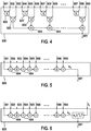
- Figur 4
- eine erste Logikschaltung zum Zusammenfassen mehrerer vorläufiger Bewertungsparameter zu einem resultierenden Bewertungsparameter,
- Figur 5
- eine zweite Logikschaltung zum Zusammenfassen mehrerer vorläufiger Bewertungsparameter zu einem resultierenden Bewertungsparameter,
Figur 6- eine dritte Logikschaltung zum Zusammenfassen mehrerer vorläufiger Bewertungsparameter zu einem resultierenden Bewertungsparameter, und
Figur 7- eine schematische Darstellung einer Stabilisierungsfunktion.
- Figure 1
- an exemplary image captured by an image sensor,
- Figure 2
- a block diagram of a signal processing according to a first embodiment of the invention,
- Figure 3
- a block diagram of a signal processing according to a second embodiment of the invention,
- Figure 4
- a first logic circuit for combining several preliminary evaluation parameters into a resulting evaluation parameter,
- Figure 5
- a second logic circuit for combining several preliminary evaluation parameters into a resulting evaluation parameter,
- Figure 6
- a third logic circuit for combining a plurality of preliminary evaluation parameters into a resulting evaluation parameter, and
- Figure 7
- a schematic representation of a stabilization function.
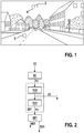
In
Der erste Bildausschnitt 2 bildet den Himmel ab und stellt somit im Wesentlichen eine blaue Fläche dar. Der zweite Bildausschnitt 3 bildet die Asphaltdecke der Straße ab und stellt somit im Wesentlichen eine graue Fläche dar. Zudem ist in beiden Bildausschnitten 2, 3 eine Texturierung vorhanden, wobei sich die Texturierung für den ersten Bildausschnitt 2 hauptsächlich aus einem Rauschen des Bildsensors ergibt, da im abgebildeten Himmel keine tatsächlichen Texturen vorhanden sind. Für den zweiten Bildausschnitt 3 ergibt sich die Texturierung aus der rauen Oberfläche der Asphaltdecke und zusätzlich aus dem Rauschen des Bildsensors. Dabei kann insbesondere eine geringfügige Bewegung des Bildsensors in Kombination mit der rauen Oberfläche der Asphaltdecke dazu führen, dass im Bereich des zweiten Bildausschnitts 3 auch ohne ein Rauschen des Bildsensors ein rauschähnliches Signal auftritt.The
Es ergibt sich, dass der erste Bildausschnitt 2 nicht für eine Korrespondenzbildung geeignet ist, da die in dem ersten Bildausschnitt 2 auftretenden Texturen lediglich durch statistische Zufallsprozesse begründet sind. Der zweite Bildausschnitt 3 ist hingegen für eine Korrespondenzbildung geeignet, da die in dem zweiten Bildausschnitt 3 auftretenden Texturen tatsächliche Referenzpunkte in der von dem Bildsensor abgebildeten Umgebung darstellen.The result is that the
Es sei darauf hingewiesen, dass die Bildausschnitte 2, 3 eine beliebige Größe und somit eine beliebige Anzahl von Bildpunkten des Bildsensors umfassen können. Im Folgenden wird beispielhaft angenommen, dass der ausgewählte Bereich des Bildsensors lediglich ein einzelnes Pixel des Bildsensors umfasst und der zugehörige Bildbereich 2, 3 somit einen einzelnen Bildpunkt umfasst.It should be pointed out that the
Das Rauschen des Bildsensors kann als Zufallsprozess betrachtet werden, dessen Parameter statistisch beschrieben sind.The noise of the image sensor can be viewed as a random process, the parameters of which are described statistically.
Das Rauschen eines einzelnen Pixels oder Bildpunktes eines Bildsensors kann im Normalfall als unabhängig vom Rauschen der Nachbarpixel betrachtet werden. Außerdem kann angenommen werden, dass alle Pixel (wegen gleichem Fertigungsprozess und gleicher Temperatur) etwa gleiche statistische Eigenschaften aufweisen. Im typischen Arbeitsbereich des Bildsensors gehorcht das Rauschen näherungsweise einer Normalverteilung. Die Varianz des Rauschens kann dabei mit ![]()
![]()
Für die weitere Verarbeitung des Bildsignals 10 kann es von Vorteil sein, die Abhängigkeit des Rauschens vom Grauwert g zu beseitigen.For the further processing of the
Zu diesem Zweck werden die originalen Grauwerte g auf Ersatz-Grauwerte h(g) abgebildet, gemäß der folgenden Funktion: ![]()
![]()
Das Tone-Mapping wird als pixelweise Operation durchgeführt (also Pixel für Pixel, unabhängig voneinander). Nach dem Tone-Mapping ist die GrauwertAbhängigkeit des Rauschens beseitigt. Die Varianz des Rauschens ist dann konstant und beträgt σC 2.The tone mapping is carried out as a pixel-by-pixel operation (i.e. pixel by pixel, independently of each other). After the tone mapping, the gray value dependency of the noise is eliminated. The variance of the noise is then constant and amounts to σ C 2 .
Die beiden bei der Korrespondenzbildung betrachten
Bilder weisen (auch nach dem Tone-Mapping) i. allg. eine unterschiedliche Varianz des Rauschens auf.Look at the two as you form correspondence
Assign images (even after tone mapping) i. generally a different variance of the noise.
Die Tone-Mapping-Funktion ist zumeist komplexer als zuvor beschrieben, insbesondere wenn es sich um einen nichtlinearen Bildsensor (z. B. HDR-Sensor, High Dynamic Range) handelt. Die Tone-Mapping-Funktion kann zeitlich veränderlich sein, z. B. sich mit jedem aufgenommenen Bild in Abhängigkeit der Kameraparameter ändern. Die Tone-Mapping-Funktion kann in einer Lookup-Tabelle oder als Rechenvorschrift abgelegt sein.The tone mapping function is mostly more complex than described above, especially when it comes to a non-linear image sensor (e.g. HDR sensor, high dynamic range). The tone mapping function can be variable over time, e.g. B. change with each recorded image depending on the camera parameters. The tone mapping function can be stored in a lookup table or as a calculation rule.
Es wird nachfolgend angenommen, dass jeder Bildpunkt durch additives Gaußsches (d. h. normal-verteiltes) Rauschen gestört ist und dass die Störungen der Bildpunkte statistisch unabhängig voneinander und identisch verteilt sind. Die Standardabweichung dieses Eingangs-Rauschprozesses wird mit σC bezeichnet. Vereinfachend soll angenommen werden, dass ein Tone-Mapping bereits stattgefunden hat, so dass σC im jeweiligen Bild konstant und unabhängig vom Grauwert g ist.It is assumed below that each pixel is disturbed by additive Gaussian (ie normally distributed) noise and that the disturbances of the pixels are statistically independently and identically distributed. The standard deviation of this input noise process is denoted by σ C. To simplify matters, it should be assumed that tone mapping has already taken place, so that σ C in the respective image is constant and independent of the gray value g.
Diese Vereinfachung ist nicht zwingend nötig: Es ist ebenso möglich, eine Grauwertabhängigkeit des Rauschens pro Pixel zu modellieren und zu berücksichtigen, jedoch bringt dies den Nachteil einer höheren Komplexität mit sich, da die Information über die Varianz des am jeweiligen Pixel vorhandenen Rauschens innerhalb der Signalverarbeitungskette weitergegeben werden muss, wenn optimale Entscheidungsschwellen genutzt werden sollen (die dann vom Grauwert g des betrachteten Pixels und von den Grauwerten der Umgebung abhängig sind).This simplification is not absolutely necessary: It is also possible to model and take into account a gray value dependence of the noise per pixel, but this has the disadvantage of greater complexity, since the information about the variance of the noise present at the respective pixel is within the signal processing chain must be passed on if optimal decision thresholds are to be used (which then depend on the gray value g of the pixel under consideration and on the gray values of the environment).
Weiterhin wird angenommen, dass eine Bildsignalverarbeitungskette zumindest teilweise aus linearen Filtern besteht: Beispielsweise aus einem Glättungsfilter, gefolgt von einer Aufspaltung in mehrere Signalpfade, wobei in jedem Signalpfad weitere Filter folgen können, beispielsweise Glättungsfilter, Ableitungsfilter, Waveletfilter und Kombinationen davon.It is also assumed that an image signal processing chain consists at least partially of linear filters: for example, of a smoothing filter, followed by a split into several signal paths, in each signal path further filters can follow, for example smoothing filters, derivative filters, wavelet filters and combinations thereof.
Dabei wird von dem Bildsensor ein Bildsignal 10 bereitgestellt, welches ein Eingangssignal eines ersten Blocks 50 bildet. Der erste Block bildet daher eine Eingangsstufe, welche dazu eingerichtet ist, das Bildsignal 10 von dem Bildsensor zu empfangen.An
Der erste Block 50 stellt z. B. ein optionales Tone-Mapping dar, das für ein vom Grauwert g unabhängiges Rauschen mit Standardabweichung σC sorgt. Von dem ersten Block 50 wird ein angepasstes Bildsignal 11, also das Bildsignal 10 nachdem das Tone-Mapping auf das Bildsignal 10 angewendet wurde, an einen zweiten Block 100 weitergeleitet.The
Der zweite Block 100 stellt z. B. ein lineares Glättungsfilter dar. Durch den Glättungsfilter wird das angepasste Bildsignal geglättet und damit ein geglättetes Bildsignal 20 erzeugt. Nach dem zweiten Block 100 spaltet sich der Signalpfad auf und das geglättete Bildsignal 20 wird in mehreren parallelen Signalpfaden weiterverarbeitet.The
Ein erster Signalpfad ist in
Es ist bekannt, dass eine Hintereinanderschaltung von linearen Filtern, beispielsweise der durch den zweiten Block 100 und den dritten Block 101 dargestellten Filter, als ein einziges lineares Filter betrachtet werden kann, welcher nachfolgend auch als Ersatzfilter 201 bezeichnet wird. Für jeden Signalpfad kann also ein Ersatzfilter 201 angegeben werden, wobei i. allg. so viele unterschiedliche Ersatzfilter 201 zu betrachten sind wie es Signalpfade gibt. Ein solches Ersatzfilter 201 bewirkt eine gewünschte gewichtete, lineare Verknüpfung von mehreren Pixelwerten (Grauwerten), wobei die Filterkoeffizienten die Gewichte darstellen. Gleichzeitig bewirkt es eine gewichtete Addition der unabhängigen Rauschprozesse. Diese soll an einem sehr einfachen Beispiel hergeleitet werden:
Betrachtet man beispielsweise die gewichtete Addition Y = w1X1 + w2X2 der beiden unkorrelierten und identisch verteilten, mittelwertfreien Zufallsvariablen X1 und X2 mit Gewichten w1 bzw. w2, so ergibt sich für die Zufallsvariable Y der gewichteten Summe: 
For example, if you consider the weighted addition Y = w 1 X 1 + w 2 X 2 of the two uncorrelated and identically distributed, mean-value-free random variables X 1 and X 2 with weights w 1 and w 2 , the weighted sum results for the random variable Y :
Dabei steht E {} für einen Erwartungswert. Wegen der Unkorreliertheit verschwindet der mittlere Term. Verallgemeinert gilt entsprechend für ein lineares Filter Y = ∑i wiXi mit Filterkoeffizienten wi und σXi = σC für die Varianzen vor und nach der Filterung die Beziehung ![]()

![]()
![]()
![]()
Voraussetzung für das Zustandekommen dieser einfachen Beziehung ist also die Unkorreliertheit der Rauschprozesse. Diese Annahme kann für Bildsensoren in der Praxis mit sehr guter Näherung getroffen werden. Voraussetzung ist hierbei, dass zwischen dem Ausgang des Bildsensors bzw. des Tone-Mappings und dem Ersatzfilter 201 keine weitere relevante Filterung stattfindet, die die getroffene Annahme der Unkorreliertheit verletzen würde.The prerequisite for the creation of this simple relationship is therefore the uncorrelated nature of the noise processes. This assumption can be made with a very good approximation for image sensors in practice. The prerequisite here is that no further relevant filtering takes place between the output of the image sensor or the tone mapping and the
Falls aber (zwischen Bildsensor bzw. Tone-Mapping und Ersatzfilter 201) weitere die Unkorreliertheit verletzende Filter vorhanden sind, so besteht eine einfache praktikable Lösung darin, diese als lineare Filter zu modellieren und in das Ersatzfilter 201 mit einzubeziehen. Somit sind alle weiteren Betrachtungen wenigstens näherungsweise gültig.However, if there are further filters that violate the uncorrelatedness (between the image sensor or tone mapping and the replacement filter 201), a simple, practicable solution is to model them as linear filters and to include them in the
In dem vierten Block 301 findet eine Verdichtung der Information des ersten Signalpfades statt. Dabei werden i. allg. nichtlineare Operationen durchgeführt.In the
So wird beispielsweise als ein Ausgangssignal 401 eine grob quantisierte (also mit wenig Bits darstellbare) Repräsentation des Eingangssignals des vierten Blocks 301 erzeugt. Das Ausgangssignal 401 kann einen Teil eines Merkmals aus dem Bild 1 darstellen oder weiterverarbeitet werden, um in die Bildung eines Merkmals einbezogen zu werden. Das Ausgangssignal 401 und die weitere Merkmalsbildung werden hier nicht weiter betrachtet. Die Merkmalsbildung erfolgt im Rahmen der an die Signalverarbeitung anschließenden Korrespondenzbildung.For example, a roughly quantized (that is, representable with few bits) representation of the input signal of the
Weiterhin findet in dem vierten Block 301 eine Bewertung des an diesem Block vorliegenden Eingangssignals s1 hinsichtlich des Rauschens statt, die nachfolgend Einzelbewertung genannt wird und durch welche ein vorläufiger Bewertungsparameter 501 bereitgestellt wird. Dabei erfolgt ein Auswerten des Bildsignals 10, um zu bestimmen, in welchem Umfang für einen ausgewählten Bereich des Bildsensors ein durch den Bildsensor verursachtes Rauschen vorliegt. Dabei wird das durch den Ersatzfilter 201 vorgefilterte Bildsignal 10 ausgewertet. Wie auch ein im Folgenden noch beschriebener resultierender Bewertungsparameter 601 beschreibt auch der vorläufige Bewertungsparameter 501, ob der jeweilige Bildausschnitt 2,3 für eine Korrespondenzbildung geeignet ist, wobei der Bildausschnitt 2, 3 dem ausgewählten Bereich des Bildsensors entspricht und wobei der Bewertungsparameter basierend auf dem bestimmten Umfang des Rauschens ermittelt wird. Dabei liegt dem vorläufigen Bewertungsparameter 501 jedoch nur das in dem dritten Block 101 vorab gefilterte Bildsignal 10 zugrunde. So wird durch den vorläufigen Bewertungsparameter 501 beispielsweise nur eine Aussage über eine Eignung eines Bildausschnittes 2, 3 für eine Korrespondenzbildung für einen bestimmten Frequenzbereich des Bildsignals 10 bereitgestellt.Furthermore, in the
Das Ermitteln des vorläufigen Bewertungsparameters 501 kann im einfachsten Falle aus einer Fallunterscheidung bestehen, wobei geprüft wird, ob der Betrag |s1| des Eingangssignals s1 für den vierten Block 301 eine Schwelle ε1A unterschreitet, wobei der Index 1 hier jeweils für den in
Der beschriebene symmetrische Schwellwert-Vergleich mit Betrachtung eines Absolutwertes stellt eine bevorzugte Ausführungsform dar, die insbesondere dann sinnvoll ist, wenn die Summe der Filter-Gewichte 0 ergibt, also 0 = ∑i wi. Ebenso vorteilhaft und besonders sinnvoll bei 0 ≠ ∑i wi ist der unsymmetrische Schwellwert-Vergleich, bei dem geprüft wird, ob das Eingangssignal s1 innerhalb oder außerhalb eines Intervalls zwischen z. B. ε1AL und ε1AR liegt (mit ε1AL < ε1AR).The described symmetrical threshold value comparison with consideration of an absolute value represents a preferred embodiment which is particularly useful when the sum of the filter weights results in 0, that is to say 0 = ∑ i w i . Equally advantageous and particularly useful with 0 ≠ ∑ i w i is the asymmetrical threshold value comparison, in which it is checked whether the input signal s 1 is inside or outside an interval between z. B. ε 1AL and ε 1AR (with ε 1AL <ε 1AR ).
Der Einfachheit halber beziehen sich die nachfolgenden Beispiele aber auf den symmetrischen Schwellwert-Vergleich.For the sake of simplicity, however, the following examples relate to the symmetrical threshold value comparison.
In alternativen Ausführungsformen erfolgt ein entsprechender Vergleich des Betrags |s1| des Eingangssignals s1 mit drei Schwellen ε1A < ε1B < ε1C, so dass vier mögliche Zustände existieren und am Ausgang des vierten Blocks 301 eine Einzelbewertung mit zwei Bit Wortbreite als vorläufiger Bewertungsparameter 501 ausgegeben wird.In alternative embodiments, the amount | s 1 | is compared accordingly of the input signal s 1 with three thresholds ε 1A <ε 1B <ε 1C , so that four possible states exist and a single evaluation with a word length of two bits is output as a
Es ist von Vorteil, die jeweilige Schwelle (z. B. ε1A) in Abhängigkeit von folgenden Einflussgrößen zu wählen: Rausch-Eigenschaften des Bildsensors, ggf. ersatzweise Rausch-Eigenschaften des Bildsignals nach einem Tone-Mapping, Rausch-Verstärkung durch das Ersatzfilter 201, oder anwendungsspezifischer Parameter, z. B. einem Faktor aA. Weiterhin ist es von Vorteil, die Einflussgrößen multiplikativ miteinander zu verknüpfen, um somit die Schwelle festzulegen.It is advantageous to select the respective threshold (e.g. ε 1A ) depending on the following influencing variables: noise properties of the image sensor, if necessary, noise properties of the image signal after tone mapping, noise amplification by the
Nachfolgend wird für das Ausführungsbeispiel also angenommen, dass die Schwelle ε1A folgendermaßen bestimmt wird: 

Der Index A steht hier für eine erste Schwelle εpA, die mit einem ersten anwendungsspezifischen Faktor aA festgelegt werden kann. Entsprechende Beziehungen existieren optional für weitere Schwellen, z. B. Index B für Schwelle εpB und Faktor aB, und so weiter.The index A stands for a first threshold ε pA , which can be set with a first application-specific factor a A. Corresponding relationships optionally exist for further thresholds, e.g. B. Index B for threshold ε pB and factor a B , and so on.
Es ist eine Anzahl von p Signalpfaden dargestellt. Ein p-ter Signalpfad mit p ∈ {1, ..., 99} beinhaltet dabei ein lineares Filter 102, 103, ... , 199 (hier also mit der Referenzzeichen 100+p bezeichnet), welches dem dritten Block 101 entspricht. Dabei weisen die linearen Filter 102, 103, ... , 199 unterschiedliche Filtereigenschaften auf, um den den Signalpfaden zugehörigen anteiligen Umfang des Rauschens zu bestimmen. Eine Zusammenfassung des jeweiligen linearen Filters 102, 103, ... , 199 eines Signalpfades mit dem vorgeschalteten linearen Filter des zweiten Blocks 100 werden als die dem jeweiligen Signalpfad zugehörigen Ersatzfilter 201, 202, ... , 299 bezeichnet (Referenzzeichen 200+p). Vorteilhafterweise sind die linearen Filter 101, 102, ..., 199 alle unterschiedlich zueinander. Entsprechend sind auch die Ersatzfilter 201, 202, ..., 299 unterschiedlich. So sind insbesondere durch eine entsprechende Auswahl der linearen Filter 101, 102, ..., 199 die mehreren zugehörigen Anteile des Umfangs des Rauschens jeweils unterschiedlichen Frequenzbereichen des Bildsignals 10 zugehörig.A number of p signal paths are shown. A p-th signal path with p ∈ {1, ..., 99} contains a
Ein p-ter Signalpfad mit p ∈ {1 ... 99} beinhaltet dabei ferner jeweils einen Block 301, 302, 303, ... 399, welcher dem vierten Block 301 des ersten Signalpfads entspricht. Die Ersatzfilter 201, 202, ..., 299 ergeben zusammen mit den Blöcken 301, 302, 303, ... 399 und einem optionalen Kombinationsblocks 600 eine Auswertungsstufe. Diese ist dazu eingerichtet, das Bildsignal 10 auszuwerten, um zu bestimmen, in welchem Umfang für einen ausgewählten Bereich des Bildsensors ein durch den Bildsensor verursachtes Rauschen vorliegt, und einen resultierenden Bewertungsparameter 601 für den Bildausschnitt 2, 3 des von dem Bildsensor erfassten Bildes zu ermitteln, welcher beschreibt, ob der Bildausschnitt 2, 3 für eine Korrespondenzbildung geeignet ist, wobei der Bildausschnitt 2, 3 dem ausgewählten Bereich des Bildsensors entspricht und wobei der resultierende Bewertungsparameter 601 basierend auf dem bestimmten Umfang des Rauschens ermittelt wird.A p-th signal path with p ∈ {1 ... 99} also contains a
An den Eingängen der Blöcke 301, 302, 303, ..., 399 liegen die Signale sp mit p ∈ {1, ..., 99} an. Wie zuvor beschrieben, findet in diesen Blöcken 301, 302, 303, ..., 399 wie auch in dem vierten Block 301 jeweils eine Einzelbewertung eines Eingangssignals statt, wobei jeweils ein Durchführen von einem oder mehreren Schwellwert-Vergleichen für den Betrag |sp| des jeweiligen Eingangssignals sp erfolgt. The signals s p with p ∈ {1, ..., 99} are present at the inputs of
Die Ergebnisse dieser Vergleiche werden als vorläufige Bewertungsparameter 501, 502, 503, ... 599 bereitgestellt und an einen optionalen Kombinationsblock 600 weitergegeben.The results of these comparisons are provided as
Aufgabe des Kombinationsblocks 600 ist eine Informationsverdichtung. Diese ist dadurch gekennzeichnet, dass ein Ausgangssignal des Kombinationsblocks 600 mit weniger Bits beschrieben werden kann als die Gesamtheit der Eingangssignale, also der vorläufigen Bewertungsparameter 501, 502, 503, ..., 599. Das Ausgangssignal hat dann i. allg. eine geringere Entropie. Es tritt ein Informationsverlust auf, der aber bewusst in Kauf genommen wird, z. B. um den Vorteil einer geringen Wortbreite zu erreichen und Übertragungsbandbreite einzusparen. Das Ausgangssignal des Kombinationsblocks 600 ist der resultierende Bewertungsparameter 601. Es werden somit durch den Kombinationsblock 600 die vorläufigen Bewertungsparameter 501, 502, 503, ..., 599 zu dem resultierenden Bewertungsparameter 601 zusammengefasst.The task of the combination block 600 is to compress information. This is characterized in that an output signal of the combination block 600 can be described with fewer bits than the entirety of the input signals, that is to say the
Die
Die addierten vorläufigen Bewertungsparameter 501, 502, 503, ..., 599 werden als Summensignal sx bezeichnet und an einem Ausgang des Kombinationsblocks 600 als resultierender Bewertungsparameter 601 bereitgestellt.The added
Wie in
Es besteht eine Vielzahl weiterer Möglichkeiten zur Ausgestaltung des Kombinationsblocks 600, um die vorläufigen Bewertungsparameter 501, 502, 503, ..., 599 geeignet miteinander zu kombinieren, beispielsweise mit logischen Operationen (AND, OR, XOR, NOT usw.), Rechenoperationen (Addition, Multiplikation usw.), Schwellwertvergleiche, Quantisierung, Lookup-Tabellen, und so weiter. Die Verknüpfung dieser Operationen kann entweder "designt" oder anhand von Trainingsdaten "trainiert" werden.There are a number of other possibilities for designing the combination block 600 in order to suitably combine the
Entscheidend ist hierbei, dass die Einzelbewertungen und somit die vorläufigen Bewertungsparameter 501, 502, 503, ..., 599 zu einer verdichteten Bewertung verknüpft werden, so dass die verdichtete Bewertung bereits eine relativ verlässliche Information darüber gibt, ob und ggf. wie weit sich das gerade prozessierte Signal, welches als Ausgangssignal 401, 402, 403, ..., 499 bereitgestellt wird, vom Rauschen abhebt. Diese verdichtete Bewertung kann dabei binärwertig sein oder einen größeren Wertebereich aufweisen.The decisive factor here is that the individual evaluations and thus the
Diese verdichtete Bewertung kann auch vektorwertig sein. In diesem Falle wird also nicht nur eine binärwertige oder "mehrwertige" Information ausgegeben, sondern mehrere solche, die zusammen betrachtet als Vektor aufgefasst werden können. Beispielsweise können die in
Auf das Ausgangssignal des Kombinationsblocks 600 und somit auf den resultierenden Bewertungsparameter 601 wird eine Stabilisierungsfunktion angewendet. Dies ist in
Der optionale Stabilisierungsblock 700 nutzt räumliche und/oder zeitliche statistische Abhängigkeiten aus, um das Ergebnis zu stabilisieren. Beispielsweise, indem die Zwischenergebnisse des in
Dies ist dadurch motiviert, dass eine örtlich und/oder zeitlich stabilere Entscheidung getroffen kann, wenn die Entscheidungen nicht einzeln (pixelweise) getroffen werden, sondern in einem örtlichen und/oder zeitlichen Kontext.This is motivated by the fact that a decision that is more stable in terms of location and / or time can be made if the decisions are not made individually (pixel by pixel), but in a local and / or temporal context.
Ein Beispiel für die gewichtete Summation in einer räumlichen Pixel-Nachbarschaft ist in
Dabei erfolgt das Auswerten des Bildsignals 10, um einen Umfang eines Rauschens zu bestimmen, für mehrere ausgewählte Bildausschnitte 2, 3 des Bildsensors, um mehrere resultierende Bewertungsparameter 601 zu ermitteln. So wird insbesondere für jedes Pixel, also für jeden Bildpunkt, oder für jedes Merkmal in dem Bild die in
In dem durch den Stabilisierungsblock 700 dargestellten Anteil der Signalverarbeitung wird auf den resultierenden Bewertungsparameter 601, welcher beispielsweise dem ersten Bildausschnitt 2 zugehörig ist, eine Stabilisierungsfunktion angewendet, wobei eine Anpassung eines Wertes des resultierenden Bewertungsparameter 601 des ersten Bildausschnitts 2 an einen resultierenden Bewertungsparameter eines dem ersten Bildausschnitt 2 benachbarten Bildausschnitts 4 erfolgt.In the portion of the signal processing represented by the
Dazu werden alle ermittelten resultierenden Bewertungsparameter 601 zumindest für eine kurze Zeit zwischengespeichert, so dass für jedes Pixel und somit für jeden Bildausschnitt 2, 3 auf die jeweiligen resultierenden Bewertungsparameter der benachbarten Pixel zugegriffen werden kann.For this purpose, all the resulting
Beispielsweise wird hierfür den in
Der so stabilisierte resultierende Bewertungsparameter 601 wird als ein Ausgangswert s2 ausgegeben und kann optional mit einer Schwelle T2 verglichen werden, die z. B. einen Wert von "700" aufweist. Alternativ zu dieser Schwellwertentscheidung kann auch eine Quantisierung stattfinden, die z. B. den 0 - 1386 Wertebereich auf einen kleineren Wertebereich von z. B. 0 - 7 abbildet.The resulting
Alle genannten Zahlen sind lediglich als Beispiele zu betrachten. Das durch den Stabilisierungsblock 700 bereitgestellte Glättungfilter ist nicht zwingend symmetrisch aufgebaut, und es muss auch nicht dicht besetzt sein. Beliebige Formen und Ausdehnungen können sich als vorteilhaft erweisen und können beispielsweise experimentell ermittelt werden.All figures mentioned are to be regarded as examples only. The smoothing filter provided by the
Die räumliche gewichtete Summation erfordert i. allg. eine Zwischen-Pufferung der resultierenden Bewertungsparameter 601 und führt i. allg. auch zu einer Verzögerung, weil das Endergebnis für das jeweilige (Referenz-)Pixel erst berechnet werden kann, wenn alle weiteren Zwischenergebnisse vorliegen.The spatial weighted summation requires i. general. an intermediate buffering of the resulting
Die gewichtete Summation kann zusätzlich oder alternativ auch in zeitlicher Richtung durchgeführt werden. Dazu werden z. B. zwischen-gepufferte Zwischenergebnisse aus einer früheren Berechnung (z. B. für das Vorgängerbild) mit einbezogen. Diese Einbeziehung erfolgt gegebenenfalls unter Nutzung einer Bewegungskompensation, beispielsweise zur Kompensation einer Rotation einer Kamera, welche den Bildsensor umfasst.The weighted summation can additionally or alternatively also be carried out in the time direction. For this purpose z. For example, buffered intermediate results from an earlier calculation (e.g. for the previous image) are included. This inclusion takes place, if necessary, using motion compensation, for example to compensate for a rotation of a camera which includes the image sensor.
Das Ergebnis des Stabilisierungsblocks 700 ist eine Entscheidung (im Falle eines binären Ergebnisses) oder eine Bewertung (im Falle eines mehr als binärwertigen Ergebnisses) über das Rauschen am jeweiligen Pixel. Die binären Werte können dabei die folgende Interpretation haben. Am Ausgang des Stabilisierungsblocks 700 wird dabei der stabilisierte resultierende Bewegungsparameter 701 bereitgestellt. Der Stabilisierungsblock 700 ist optional. Die um Folgenden beschriebenen Bedeutungen der Werte des stabilisierten resultierenden Bewegungsparameters 601 können in gleicher Weise unmittelbar auf den (nicht stabilisierten) resultierenden Bewegungsparameters 601 angewendet werden.The result of the
Ist der stabilisierte resultierende Bewegungsparameter 701 oder der resultierende Bewegungsparameter 601 ein binärer Wert, so kann dieser wie folgt interpretiert werden:
- Wert = 0 bedeutet: Der für dieses Pixel bestimmte Merkmalsvektor ist wahrscheinlich vom Rauschen signifikant beeinflusst und sollte daher nicht für die Korrespondenzbildung (oder eine andere Weiterverarbeitung) verwendet werden.
- Wert = 1 bedeutet: Der Merkmalsvektor ist wahrscheinlich nicht vom Rauschen beeinflusst und kann daher für die Korrespondenzbildung usw. verwendet werden.
- Value = 0 means: The feature vector determined for this pixel is likely to be significantly influenced by the noise and should therefore not be used for the formation of correspondence (or any other further processing).
- Value = 1 means: The feature vector is probably not influenced by the noise and can therefore be used for the formation of correspondence etc.
Bei einer Quantisierung des stabilisierten resultierenden Bewegungsparameters 701 oder des resultierenden Bewegungsparameters 601 auf vier Werte kann die Interpretation lauten:
- Wert = 0 bedeutet: Der Merkmalsvektor ist wahrscheinlich vom Rauschen beeinflusst und wird daher nicht für die Korrespondenzbildung verwendet.
- Wert = 1 bedeutet: Der Merkmalsvektor kann vom Rauschen beeinflusst sein. Ergebnissen, die mit oder für diesen Merkmalsvektor gewonnen werden, sollte daher kein allzu großes Vertrauen geschenkt werden.
- Wert = 2 bedeutet: Der Merkmalsvektor ist wahrscheinlich nicht vom Rauschen beeinflusst und kann daher für die Korrespondenzbildung normal verwendet werden.
- Wert = 3 bedeutet: Der Merkmalsvektor ist nicht vom Rauschen beeinflusst. Er ist so deutlich vom Rauschniveau entfernt, dass den entsprechenden Ergebnissen besonderes Vertrauen geschenkt werden kann.
- Value = 0 means: The feature vector is probably influenced by the noise and is therefore not used for the formation of the correspondence.
- Value = 1 means: The feature vector can be influenced by noise. Results that are obtained with or for this feature vector should therefore not be trusted too much.
- Value = 2 means: The feature vector is probably not influenced by the noise and can therefore be used normally for the formation of correspondence.
- Value = 3 means: The feature vector is not influenced by the noise. It is so far removed from the noise level that special trust can be given to the corresponding results.
Die gewählte Reihenfolge des Kombinationsblocks 600 und des Stabilisierungsblocks 700 ist hier lediglich beispielhaft zu verstehen. Sie kann auch umgekehrt sein, um zuerst die räumliche/zeitliche Nachbarschaft einzubeziehen und anschließend eine Informationsverdichtung zu erreichen. Auch können die Funktionen dieser Blöcke 600, 700 gegenseitig ineinander verwoben sein und in einem gemeinsamen Block dargestellt werden.The selected sequence of the combination block 600 and the
Zusammenfassend ermöglicht das erfindungsgemäße Verfahren eine Zusatzinformation zu einem Merkmal anzugeben, die in Abhängigkeit des "Abstands zum Rauschen" ein mehr oder weniger großes Vertrauen in dieses Merkmal ausdrückt, wobei dieses Vertrauens- oder Gütemaß sehr kompakt beschrieben sein kann (z. B. mit 1 Bit oder mit wenigen Bits) und an nachfolgende Algorithmen weitergereicht oder zur weiteren Verwendung effizient gespeichert werden kann.In summary, the method according to the invention makes it possible to specify additional information on a feature which, depending on the "distance to noise", expresses a greater or lesser degree of confidence in this feature, whereby this confidence or quality measure can be described very compactly (e.g. with 1 Bit or with a few bits) and can be passed on to subsequent algorithms or efficiently stored for further use.
In der bevorzugten Ausführungsform wird die erfindungsgemäße Information pro Pixel bzw. pro Merkmal ermittelt und angehängt. Es ist jedoch auch möglich, diese seltener zu ermitteln und bereitzustellen, beispielsweise jeweils für eine Gruppe von Pixel oder Merkmalen oder aber als Binärbild, das dann mit bekannten Methoden zur Datenkompression codiert und decodiert werden kann. In diesem Fall ist auch eine Repräsentation mit weniger als 1 Bit pro Pixel bzw. Merkmal möglich.In the preferred embodiment, the information according to the invention is determined and appended per pixel or per feature. However, it is also possible to determine and provide these less frequently, for example in each case for a group of pixels or features or else as a binary image, which can then be encoded and decoded using known methods for data compression. In this case, a representation with less than 1 bit per pixel or feature is also possible.
Claims (8)
- Method for assessing image details for forming a correspondence, wherein mutually corresponding features in two individual images are ascertained, comprising:- receiving an image signal (10) from an image sensor,- evaluating the image signal (10) to determine to what extent noise caused by the image sensor is present for a selected region of the image sensor, and- ascertaining a resulting assessment parameter (601) for an image detail (2, 3) of an image captured by the image sensor, which assessment parameter (601) describes whether the image detail (2, 3) is suitable for forming a correspondence, wherein the image detail (2, 3) corresponds to the selected region of the image sensor and wherein the resulting assessment parameter (601) is ascertained based on the determined extent of the noise, characterized in that for the selected region of the image sensor in each case a proportional extent of the noise in different signal paths is determined, in that the image signal (10) in the different signal paths is in each case differently filtered, and the resulting assessment parameter (601) for the image detail (2, 3) is determined based on the respective proportional extent of the noise from all signal paths.
- Method according to Claim 1, characterized in that in each case different frequency regions of the image signal are associated with each proportional extent of the noise.
- Method according to one of Claims 1 to 2, characterized in that a preliminary assessment parameter (501, 502, 503, ..., 599) is ascertained from each proportional extent of the noise and the preliminary assessment parameters (501, 502, 503, ..., 599) are combined to form the resulting assessment parameter (601) .
- Method according to one of the preceding claims, characterized in that dynamic compression is applied to the image signal (10) before the image signal (10) is evaluated.
- Method according to one of the preceding claims, characterized in that the resulting assessment parameter (601) is a binary value, indicates a degree of suitability for forming a correspondence in multiple stages, or is a vectorial value.
- Method according to one of the preceding claims, characterized in that the evaluation of the image signal (10) for determining an extent of the noise is performed for a plurality of selected regions of the image sensor so as to ascertain a plurality of resulting assessment parameters (601).
- Method according to Claim 6, characterized in that a stabilization function is applied to one of the resulting assessment parameters (601) that is associated with a first image detail (2), wherein spatial and/or temporal filtering is effected on the basis of neighbouring resulting assessment parameters (601).
- Apparatus for assessing image details for forming a correspondence, wherein mutually corresponding features in two individual images are ascertained, comprising:- an input stage (50) configured for receiving an image signal (10) from an image sensor and- an evaluation stage configured for:• evaluating the image signal (10) to determine to what extent noise caused by the image sensor is present for a selected region of the image sensor,• ascertaining a resulting assessment parameter (601) for an image detail (2, 3) of an image captured by the image sensor, which assessment parameter (601) describes whether the image detail (2, 3) is suitable for forming a correspondence, wherein the image detail (2, 3) corresponds to the selected region of the image sensor and wherein the resulting assessment parameter (601) is ascertained based on the determined extent of the noise, characterized in that for the selected region of the image sensor in each case a proportional extent of the noise in different signal paths is determined, in that the image signal (10) in the different signal paths is in each case differently filtered, and the resulting assessment parameter (601) for the image detail (2, 3) is determined based on the respective proportional extent of the noise from all signal paths.
Applications Claiming Priority (2)
| Application Number | Priority Date | Filing Date | Title |
|---|---|---|---|
| DE102017212339.7A DE102017212339A1 (en) | 2017-07-19 | 2017-07-19 | Method and device for evaluating image sections for correspondence formation |
| PCT/EP2018/065317 WO2019015877A1 (en) | 2017-07-19 | 2018-06-11 | Method and device for analysing image sections for a correspondence calculation |
Publications (2)
| Publication Number | Publication Date |
|---|---|
| EP3655920A1 EP3655920A1 (en) | 2020-05-27 |
| EP3655920B1 true EP3655920B1 (en) | 2021-03-31 |
Family
ID=62599592
Family Applications (1)
| Application Number | Title | Priority Date | Filing Date |
|---|---|---|---|
| EP18731048.7A Active EP3655920B1 (en) | 2017-07-19 | 2018-06-11 | Method and device for analysing image sections for a correspondence calculation |
Country Status (6)
| Country | Link |
|---|---|
| US (1) | US11100624B2 (en) |
| EP (1) | EP3655920B1 (en) |
| JP (1) | JP6889327B2 (en) |
| CN (1) | CN110998652B (en) |
| DE (1) | DE102017212339A1 (en) |
| WO (1) | WO2019015877A1 (en) |
Families Citing this family (2)
| Publication number | Priority date | Publication date | Assignee | Title |
|---|---|---|---|---|
| DE102017212339A1 (en) * | 2017-07-19 | 2019-01-24 | Robert Bosch Gmbh | Method and device for evaluating image sections for correspondence formation |
| DE102020202973A1 (en) | 2020-03-09 | 2021-09-09 | Robert Bosch Gesellschaft mit beschränkter Haftung | Method and apparatus for processing images |
Family Cites Families (28)
| Publication number | Priority date | Publication date | Assignee | Title |
|---|---|---|---|---|
| JP3465988B2 (en) * | 1994-04-27 | 2003-11-10 | 松下電器産業株式会社 | Method and apparatus for estimating movement and depth |
| BR0215934A (en) * | 2002-11-06 | 2005-08-16 | Agency Science Tech & Res | Method for generating a quality-oriented significance map to evaluate the quality of an image or video |
| US7512286B2 (en) * | 2003-10-27 | 2009-03-31 | Hewlett-Packard Development Company, L.P. | Assessing image quality |
| US7693304B2 (en) * | 2005-05-12 | 2010-04-06 | Hewlett-Packard Development Company, L.P. | Method and system for image quality calculation |
| GB2443663A (en) * | 2006-07-31 | 2008-05-14 | Hewlett Packard Development Co | Electronic image capture with reduced noise |
| JP4821548B2 (en) * | 2006-10-02 | 2011-11-24 | コニカミノルタホールディングス株式会社 | Image processing apparatus, image processing apparatus control method, and image processing apparatus control program |
| DE102007003060A1 (en) | 2007-01-15 | 2008-07-17 | Technische Universität Ilmenau | Method for determining the quality of a measuring point in edge detection in optical length measuring technology |
| JP2009104366A (en) | 2007-10-23 | 2009-05-14 | Suzuki Motor Corp | Stereo image processing method |
| RU2405200C2 (en) * | 2008-07-17 | 2010-11-27 | Корпорация "Самсунг Электроникс Ко., Лтд" | Method and device for fast noise filtration in digital images |
| US20100277774A1 (en) * | 2009-05-04 | 2010-11-04 | Certifi Media Inc. | Image quality indicator responsive to image processing |
| EP2275990B1 (en) | 2009-07-06 | 2012-09-26 | Sick Ag | 3D sensor |
| WO2011011542A1 (en) * | 2009-07-21 | 2011-01-27 | Integrated Device Technology, Inc. | A method and system for detection and enhancement of video images |
| RU2441281C1 (en) * | 2011-01-14 | 2012-01-27 | Закрытое Акционерное Общество "Импульс" | Method to assess noise of digital x-ray pictures |
| US8792710B2 (en) * | 2012-07-24 | 2014-07-29 | Intel Corporation | Stereoscopic depth reconstruction with probabilistic pixel correspondence search |
| JP5997645B2 (en) * | 2013-03-26 | 2016-09-28 | キヤノン株式会社 | Image processing apparatus and method, and imaging apparatus |
| EP2808841A1 (en) * | 2013-05-31 | 2014-12-03 | Thomson Licensing | Method and apparatus for generating a noise profile of noise in an image sequence |
| JP6369019B2 (en) * | 2013-12-12 | 2018-08-08 | セイコーエプソン株式会社 | Image evaluation apparatus and image evaluation program |
| JP6253450B2 (en) | 2014-02-28 | 2017-12-27 | オリンパス株式会社 | Image processing apparatus, image processing method, and program |
| JP6415066B2 (en) * | 2014-03-20 | 2018-10-31 | キヤノン株式会社 | Information processing apparatus, information processing method, position and orientation estimation apparatus, robot system |
| US9330340B1 (en) * | 2014-05-06 | 2016-05-03 | Google Inc. | Noise estimation for images using polynomial relationship for pixel values of image features |
| JP6397284B2 (en) * | 2014-09-16 | 2018-09-26 | キヤノン株式会社 | Image processing apparatus, image processing method, and program |
| US9892517B2 (en) * | 2014-12-19 | 2018-02-13 | Apical Ltd. | Sensor noise profile |
| PL411631A1 (en) * | 2015-03-18 | 2016-09-26 | Politechnika Poznańska | System for generating a map of depth and method for generating a map of depth |
| JP6548556B2 (en) * | 2015-11-17 | 2019-07-24 | 富士フイルム株式会社 | Grid quality judging device, method and program |
| US9922411B2 (en) * | 2015-11-30 | 2018-03-20 | Disney Enterprises, Inc. | Saliency-weighted video quality assessment |
| DE102017212339A1 (en) * | 2017-07-19 | 2019-01-24 | Robert Bosch Gmbh | Method and device for evaluating image sections for correspondence formation |
| KR102466998B1 (en) * | 2018-02-09 | 2022-11-14 | 삼성전자주식회사 | Method and apparatus for image fusion |
| JP7412983B2 (en) * | 2019-02-04 | 2024-01-15 | キヤノン株式会社 | Information processing device, information processing method, and program |
-
2017
- 2017-07-19 DE DE102017212339.7A patent/DE102017212339A1/en active Pending
-
2018
- 2018-06-11 CN CN201880048314.5A patent/CN110998652B/en active Active
- 2018-06-11 US US16/631,694 patent/US11100624B2/en active Active
- 2018-06-11 JP JP2020502319A patent/JP6889327B2/en active Active
- 2018-06-11 EP EP18731048.7A patent/EP3655920B1/en active Active
- 2018-06-11 WO PCT/EP2018/065317 patent/WO2019015877A1/en unknown
Also Published As
| Publication number | Publication date |
|---|---|
| DE102017212339A1 (en) | 2019-01-24 |
| CN110998652B (en) | 2024-02-09 |
| CN110998652A (en) | 2020-04-10 |
| WO2019015877A1 (en) | 2019-01-24 |
| JP6889327B2 (en) | 2021-06-18 |
| US11100624B2 (en) | 2021-08-24 |
| US20200151864A1 (en) | 2020-05-14 |
| EP3655920A1 (en) | 2020-05-27 |
| JP2020528182A (en) | 2020-09-17 |
Similar Documents
| Publication | Publication Date | Title |
|---|---|---|
| DE602005004694T2 (en) | Method and apparatus for locally adaptive image processing filters | |
| DE102005025629A1 (en) | Image processing method for reducing blocking artifacts | |
| DE112016001040T5 (en) | Method and system for real-time noise removal and image enhancement of high dynamic range images | |
| DE10239801A1 (en) | Process for extracting texture features from a multi-channel image | |
| DE102016216795A1 (en) | Method for determining result image data | |
| EP3655920B1 (en) | Method and device for analysing image sections for a correspondence calculation | |
| DE4105516A1 (en) | METHOD AND DEVICE FOR FILTERING SIGNALS | |
| DE102020134755A1 (en) | PROCESSING VIDEO FRAMES VIA NEURONAL FOLDING NETWORK USING STATISTICS OF PREVIOUS FRAMES | |
| EP2023638A2 (en) | Method for reducing image artefacts | |
| EP0897247A2 (en) | Method for computing motion vectors | |
| EP1156681A2 (en) | Method and apparatus for measuring a picture noise content | |
| DE102008046505B4 (en) | Process for image processing of stereo images | |
| DE19851544C1 (en) | Generate a rolled fingerprint image from a series of individual images | |
| DE60306800T2 (en) | METHOD AND SYSTEM FOR MEASURING VIDEO IMAGE INTERRUPTION, PRODUCED BY CODING TO BITRATE REDUCTION | |
| DE102021101468A1 (en) | Method for generating valid distance data for a time-of-flight camera | |
| AT508873A1 (en) | METHOD FOR RECORDING AN IMAGE | |
| EP3142068A1 (en) | Method for three-dimensional recording of objects | |
| EP3214602A1 (en) | Method for three-dimensional recording of objects | |
| DE102009009572B3 (en) | Method for entropy-based determination of object edge curves | |
| DE10326031B4 (en) | Method for adaptive edge detection | |
| EP1185084A2 (en) | Image compression method and image coder | |
| WO2019072454A1 (en) | Brightness and contrast optimisation for images in real time | |
| DE19810162C2 (en) | Process for image analysis according to stochastic properties | |
| EP2501133A2 (en) | Method and device for reducing bandwidth for image data | |
| DE102012218854B4 (en) | Method and device for compressing image data |
Legal Events
| Date | Code | Title | Description |
|---|---|---|---|
| STAA | Information on the status of an ep patent application or granted ep patent |
Free format text: STATUS: UNKNOWN |
|
| STAA | Information on the status of an ep patent application or granted ep patent |
Free format text: STATUS: THE INTERNATIONAL PUBLICATION HAS BEEN MADE |
|
| PUAI | Public reference made under article 153(3) epc to a published international application that has entered the european phase |
Free format text: ORIGINAL CODE: 0009012 |
|
| STAA | Information on the status of an ep patent application or granted ep patent |
Free format text: STATUS: REQUEST FOR EXAMINATION WAS MADE |
|
| 17P | Request for examination filed |
Effective date: 20200219 |
|
| AK | Designated contracting states |
Kind code of ref document: A1 Designated state(s): AL AT BE BG CH CY CZ DE DK EE ES FI FR GB GR HR HU IE IS IT LI LT LU LV MC MK MT NL NO PL PT RO RS SE SI SK SM TR |
|
| AX | Request for extension of the european patent |
Extension state: BA ME |
|
| DAV | Request for validation of the european patent (deleted) | ||
| DAX | Request for extension of the european patent (deleted) | ||
| GRAP | Despatch of communication of intention to grant a patent |
Free format text: ORIGINAL CODE: EPIDOSNIGR1 |
|
| STAA | Information on the status of an ep patent application or granted ep patent |
Free format text: STATUS: GRANT OF PATENT IS INTENDED |
|
| INTG | Intention to grant announced |
Effective date: 20210118 |
|
| GRAS | Grant fee paid |
Free format text: ORIGINAL CODE: EPIDOSNIGR3 |
|
| GRAA | (expected) grant |
Free format text: ORIGINAL CODE: 0009210 |
|
| STAA | Information on the status of an ep patent application or granted ep patent |
Free format text: STATUS: THE PATENT HAS BEEN GRANTED |
|
| AK | Designated contracting states |
Kind code of ref document: B1 Designated state(s): AL AT BE BG CH CY CZ DE DK EE ES FI FR GB GR HR HU IE IS IT LI LT LU LV MC MK MT NL NO PL PT RO RS SE SI SK SM TR |
|
| REG | Reference to a national code |
Ref country code: GB Ref legal event code: FG4D Free format text: NOT ENGLISH Ref country code: CH Ref legal event code: EP |
|
| REG | Reference to a national code |
Ref country code: AT Ref legal event code: REF Ref document number: 1377792 Country of ref document: AT Kind code of ref document: T Effective date: 20210415 |
|
| REG | Reference to a national code |
Ref country code: DE Ref legal event code: R096 Ref document number: 502018004565 Country of ref document: DE |
|
| REG | Reference to a national code |
Ref country code: IE Ref legal event code: FG4D Free format text: LANGUAGE OF EP DOCUMENT: GERMAN |
|
| REG | Reference to a national code |
Ref country code: LT Ref legal event code: MG9D |
|
| PG25 | Lapsed in a contracting state [announced via postgrant information from national office to epo] |
Ref country code: NO Free format text: LAPSE BECAUSE OF FAILURE TO SUBMIT A TRANSLATION OF THE DESCRIPTION OR TO PAY THE FEE WITHIN THE PRESCRIBED TIME-LIMIT Effective date: 20210630 Ref country code: HR Free format text: LAPSE BECAUSE OF FAILURE TO SUBMIT A TRANSLATION OF THE DESCRIPTION OR TO PAY THE FEE WITHIN THE PRESCRIBED TIME-LIMIT Effective date: 20210331 Ref country code: FI Free format text: LAPSE BECAUSE OF FAILURE TO SUBMIT A TRANSLATION OF THE DESCRIPTION OR TO PAY THE FEE WITHIN THE PRESCRIBED TIME-LIMIT Effective date: 20210331 Ref country code: BG Free format text: LAPSE BECAUSE OF FAILURE TO SUBMIT A TRANSLATION OF THE DESCRIPTION OR TO PAY THE FEE WITHIN THE PRESCRIBED TIME-LIMIT Effective date: 20210630 |
|
| PG25 | Lapsed in a contracting state [announced via postgrant information from national office to epo] |
Ref country code: SE Free format text: LAPSE BECAUSE OF FAILURE TO SUBMIT A TRANSLATION OF THE DESCRIPTION OR TO PAY THE FEE WITHIN THE PRESCRIBED TIME-LIMIT Effective date: 20210331 Ref country code: RS Free format text: LAPSE BECAUSE OF FAILURE TO SUBMIT A TRANSLATION OF THE DESCRIPTION OR TO PAY THE FEE WITHIN THE PRESCRIBED TIME-LIMIT Effective date: 20210331 Ref country code: LV Free format text: LAPSE BECAUSE OF FAILURE TO SUBMIT A TRANSLATION OF THE DESCRIPTION OR TO PAY THE FEE WITHIN THE PRESCRIBED TIME-LIMIT Effective date: 20210331 |
|
| REG | Reference to a national code |
Ref country code: NL Ref legal event code: MP Effective date: 20210331 |
|
| PG25 | Lapsed in a contracting state [announced via postgrant information from national office to epo] |
Ref country code: EE Free format text: LAPSE BECAUSE OF FAILURE TO SUBMIT A TRANSLATION OF THE DESCRIPTION OR TO PAY THE FEE WITHIN THE PRESCRIBED TIME-LIMIT Effective date: 20210331 Ref country code: CZ Free format text: LAPSE BECAUSE OF FAILURE TO SUBMIT A TRANSLATION OF THE DESCRIPTION OR TO PAY THE FEE WITHIN THE PRESCRIBED TIME-LIMIT Effective date: 20210331 Ref country code: LT Free format text: LAPSE BECAUSE OF FAILURE TO SUBMIT A TRANSLATION OF THE DESCRIPTION OR TO PAY THE FEE WITHIN THE PRESCRIBED TIME-LIMIT Effective date: 20210331 Ref country code: SM Free format text: LAPSE BECAUSE OF FAILURE TO SUBMIT A TRANSLATION OF THE DESCRIPTION OR TO PAY THE FEE WITHIN THE PRESCRIBED TIME-LIMIT Effective date: 20210331 Ref country code: NL Free format text: LAPSE BECAUSE OF FAILURE TO SUBMIT A TRANSLATION OF THE DESCRIPTION OR TO PAY THE FEE WITHIN THE PRESCRIBED TIME-LIMIT Effective date: 20210331 |
|
| PG25 | Lapsed in a contracting state [announced via postgrant information from national office to epo] |
Ref country code: PL Free format text: LAPSE BECAUSE OF FAILURE TO SUBMIT A TRANSLATION OF THE DESCRIPTION OR TO PAY THE FEE WITHIN THE PRESCRIBED TIME-LIMIT Effective date: 20210331 Ref country code: PT Free format text: LAPSE BECAUSE OF FAILURE TO SUBMIT A TRANSLATION OF THE DESCRIPTION OR TO PAY THE FEE WITHIN THE PRESCRIBED TIME-LIMIT Effective date: 20210802 Ref country code: RO Free format text: LAPSE BECAUSE OF FAILURE TO SUBMIT A TRANSLATION OF THE DESCRIPTION OR TO PAY THE FEE WITHIN THE PRESCRIBED TIME-LIMIT Effective date: 20210331 Ref country code: SK Free format text: LAPSE BECAUSE OF FAILURE TO SUBMIT A TRANSLATION OF THE DESCRIPTION OR TO PAY THE FEE WITHIN THE PRESCRIBED TIME-LIMIT Effective date: 20210331 Ref country code: IS Free format text: LAPSE BECAUSE OF FAILURE TO SUBMIT A TRANSLATION OF THE DESCRIPTION OR TO PAY THE FEE WITHIN THE PRESCRIBED TIME-LIMIT Effective date: 20210731 |
|
| REG | Reference to a national code |
Ref country code: DE Ref legal event code: R097 Ref document number: 502018004565 Country of ref document: DE |
|
| PG25 | Lapsed in a contracting state [announced via postgrant information from national office to epo] |
Ref country code: ES Free format text: LAPSE BECAUSE OF FAILURE TO SUBMIT A TRANSLATION OF THE DESCRIPTION OR TO PAY THE FEE WITHIN THE PRESCRIBED TIME-LIMIT Effective date: 20210331 Ref country code: DK Free format text: LAPSE BECAUSE OF FAILURE TO SUBMIT A TRANSLATION OF THE DESCRIPTION OR TO PAY THE FEE WITHIN THE PRESCRIBED TIME-LIMIT Effective date: 20210331 Ref country code: AL Free format text: LAPSE BECAUSE OF FAILURE TO SUBMIT A TRANSLATION OF THE DESCRIPTION OR TO PAY THE FEE WITHIN THE PRESCRIBED TIME-LIMIT Effective date: 20210331 Ref country code: MC Free format text: LAPSE BECAUSE OF FAILURE TO SUBMIT A TRANSLATION OF THE DESCRIPTION OR TO PAY THE FEE WITHIN THE PRESCRIBED TIME-LIMIT Effective date: 20210331 |
|
| REG | Reference to a national code |
Ref country code: CH Ref legal event code: PL |
|
| PLBE | No opposition filed within time limit |
Free format text: ORIGINAL CODE: 0009261 |
|
| STAA | Information on the status of an ep patent application or granted ep patent |
Free format text: STATUS: NO OPPOSITION FILED WITHIN TIME LIMIT |
|
| 26N | No opposition filed |
Effective date: 20220104 |
|
| REG | Reference to a national code |
Ref country code: BE Ref legal event code: MM Effective date: 20210630 |
|
| PG25 | Lapsed in a contracting state [announced via postgrant information from national office to epo] |
Ref country code: LU Free format text: LAPSE BECAUSE OF NON-PAYMENT OF DUE FEES Effective date: 20210611 |
|
| PG25 | Lapsed in a contracting state [announced via postgrant information from national office to epo] |
Ref country code: LI Free format text: LAPSE BECAUSE OF NON-PAYMENT OF DUE FEES Effective date: 20210630 Ref country code: CH Free format text: LAPSE BECAUSE OF NON-PAYMENT OF DUE FEES Effective date: 20210630 Ref country code: IE Free format text: LAPSE BECAUSE OF NON-PAYMENT OF DUE FEES Effective date: 20210611 |
|
| PG25 | Lapsed in a contracting state [announced via postgrant information from national office to epo] |
Ref country code: IS Free format text: LAPSE BECAUSE OF FAILURE TO SUBMIT A TRANSLATION OF THE DESCRIPTION OR TO PAY THE FEE WITHIN THE PRESCRIBED TIME-LIMIT Effective date: 20210731 |
|
| PG25 | Lapsed in a contracting state [announced via postgrant information from national office to epo] |
Ref country code: BE Free format text: LAPSE BECAUSE OF NON-PAYMENT OF DUE FEES Effective date: 20210630 |
|
| GBPC | Gb: european patent ceased through non-payment of renewal fee |
Effective date: 20220611 |
|
| PG25 | Lapsed in a contracting state [announced via postgrant information from national office to epo] |
Ref country code: GB Free format text: LAPSE BECAUSE OF NON-PAYMENT OF DUE FEES Effective date: 20220611 |
|
| P01 | Opt-out of the competence of the unified patent court (upc) registered |
Effective date: 20230509 |
|
| PG25 | Lapsed in a contracting state [announced via postgrant information from national office to epo] |
Ref country code: CY Free format text: LAPSE BECAUSE OF FAILURE TO SUBMIT A TRANSLATION OF THE DESCRIPTION OR TO PAY THE FEE WITHIN THE PRESCRIBED TIME-LIMIT Effective date: 20210331 |
|
| PG25 | Lapsed in a contracting state [announced via postgrant information from national office to epo] |
Ref country code: HU Free format text: LAPSE BECAUSE OF FAILURE TO SUBMIT A TRANSLATION OF THE DESCRIPTION OR TO PAY THE FEE WITHIN THE PRESCRIBED TIME-LIMIT; INVALID AB INITIO Effective date: 20180611 Ref country code: GR Free format text: LAPSE BECAUSE OF FAILURE TO SUBMIT A TRANSLATION OF THE DESCRIPTION OR TO PAY THE FEE WITHIN THE PRESCRIBED TIME-LIMIT Effective date: 20210331 |
|
| PGFP | Annual fee paid to national office [announced via postgrant information from national office to epo] |
Ref country code: FR Payment date: 20230621 Year of fee payment: 6 |
|
| PGFP | Annual fee paid to national office [announced via postgrant information from national office to epo] |
Ref country code: IT Payment date: 20230630 Year of fee payment: 6 |
|
| PGFP | Annual fee paid to national office [announced via postgrant information from national office to epo] |
Ref country code: DE Payment date: 20230817 Year of fee payment: 6 |
|
| PG25 | Lapsed in a contracting state [announced via postgrant information from national office to epo] |
Ref country code: MK Free format text: LAPSE BECAUSE OF FAILURE TO SUBMIT A TRANSLATION OF THE DESCRIPTION OR TO PAY THE FEE WITHIN THE PRESCRIBED TIME-LIMIT Effective date: 20210331 |