EP3655724B1 - Method for estimating the movement of an object moving in a magnetic field - Google Patents
Method for estimating the movement of an object moving in a magnetic field Download PDFInfo
- Publication number
- EP3655724B1 EP3655724B1 EP18752592.8A EP18752592A EP3655724B1 EP 3655724 B1 EP3655724 B1 EP 3655724B1 EP 18752592 A EP18752592 A EP 18752592A EP 3655724 B1 EP3655724 B1 EP 3655724B1
- Authority
- EP
- European Patent Office
- Prior art keywords
- magnetic
- magnetic field
- movement
- component
- measurement means
- Prior art date
- Legal status (The legal status is an assumption and is not a legal conclusion. Google has not performed a legal analysis and makes no representation as to the accuracy of the status listed.)
- Active
Links
- 230000033001 locomotion Effects 0.000 title claims description 64
- 238000000034 method Methods 0.000 title claims description 48
- 238000005259 measurement Methods 0.000 claims description 40
- 238000012545 processing Methods 0.000 claims description 21
- 230000001133 acceleration Effects 0.000 claims description 14
- 230000006870 function Effects 0.000 claims description 13
- 239000011159 matrix material Substances 0.000 claims description 10
- 238000004590 computer program Methods 0.000 claims description 6
- 238000001914 filtration Methods 0.000 description 9
- 238000004891 communication Methods 0.000 description 8
- 238000004364 calculation method Methods 0.000 description 6
- 238000011156 evaluation Methods 0.000 description 6
- 238000013500 data storage Methods 0.000 description 4
- 230000005684 electric field Effects 0.000 description 3
- 230000010354 integration Effects 0.000 description 3
- 239000007787 solid Substances 0.000 description 3
- 230000006399 behavior Effects 0.000 description 2
- 230000005611 electricity Effects 0.000 description 2
- 241001028048 Nicola Species 0.000 description 1
- 230000003044 adaptive effect Effects 0.000 description 1
- 238000013459 approach Methods 0.000 description 1
- 230000005540 biological transmission Effects 0.000 description 1
- 230000000295 complement effect Effects 0.000 description 1
- 210000005045 desmin Anatomy 0.000 description 1
- 238000011161 development Methods 0.000 description 1
- 238000010586 diagram Methods 0.000 description 1
- 230000008034 disappearance Effects 0.000 description 1
- 210000004247 hand Anatomy 0.000 description 1
- 238000005404 magnetometry Methods 0.000 description 1
- 239000002184 metal Substances 0.000 description 1
- 238000012986 modification Methods 0.000 description 1
- 230000004048 modification Effects 0.000 description 1
- 230000002441 reversible effect Effects 0.000 description 1
- 238000005070 sampling Methods 0.000 description 1
- 230000035945 sensitivity Effects 0.000 description 1
- 230000002123 temporal effect Effects 0.000 description 1
- 230000000007 visual effect Effects 0.000 description 1
- 210000000707 wrist Anatomy 0.000 description 1
Images

Classifications
-
- G—PHYSICS
- G01—MEASURING; TESTING
- G01C—MEASURING DISTANCES, LEVELS OR BEARINGS; SURVEYING; NAVIGATION; GYROSCOPIC INSTRUMENTS; PHOTOGRAMMETRY OR VIDEOGRAMMETRY
- G01C21/00—Navigation; Navigational instruments not provided for in groups G01C1/00 - G01C19/00
- G01C21/04—Navigation; Navigational instruments not provided for in groups G01C1/00 - G01C19/00 by terrestrial means
- G01C21/08—Navigation; Navigational instruments not provided for in groups G01C1/00 - G01C19/00 by terrestrial means involving use of the magnetic field of the earth
-
- G—PHYSICS
- G01—MEASURING; TESTING
- G01C—MEASURING DISTANCES, LEVELS OR BEARINGS; SURVEYING; NAVIGATION; GYROSCOPIC INSTRUMENTS; PHOTOGRAMMETRY OR VIDEOGRAMMETRY
- G01C21/00—Navigation; Navigational instruments not provided for in groups G01C1/00 - G01C19/00
- G01C21/005—Navigation; Navigational instruments not provided for in groups G01C1/00 - G01C19/00 with correlation of navigation data from several sources, e.g. map or contour matching
-
- G—PHYSICS
- G01—MEASURING; TESTING
- G01C—MEASURING DISTANCES, LEVELS OR BEARINGS; SURVEYING; NAVIGATION; GYROSCOPIC INSTRUMENTS; PHOTOGRAMMETRY OR VIDEOGRAMMETRY
- G01C21/00—Navigation; Navigational instruments not provided for in groups G01C1/00 - G01C19/00
- G01C21/10—Navigation; Navigational instruments not provided for in groups G01C1/00 - G01C19/00 by using measurements of speed or acceleration
- G01C21/12—Navigation; Navigational instruments not provided for in groups G01C1/00 - G01C19/00 by using measurements of speed or acceleration executed aboard the object being navigated; Dead reckoning
- G01C21/16—Navigation; Navigational instruments not provided for in groups G01C1/00 - G01C19/00 by using measurements of speed or acceleration executed aboard the object being navigated; Dead reckoning by integrating acceleration or speed, i.e. inertial navigation
- G01C21/165—Navigation; Navigational instruments not provided for in groups G01C1/00 - G01C19/00 by using measurements of speed or acceleration executed aboard the object being navigated; Dead reckoning by integrating acceleration or speed, i.e. inertial navigation combined with non-inertial navigation instruments
- G01C21/1654—Navigation; Navigational instruments not provided for in groups G01C1/00 - G01C19/00 by using measurements of speed or acceleration executed aboard the object being navigated; Dead reckoning by integrating acceleration or speed, i.e. inertial navigation combined with non-inertial navigation instruments with electromagnetic compass
Definitions
- the present invention relates to the field of navigation without GPS.
- So-called magneto-inertial navigation techniques make it possible to precisely estimate the speed (and hence the position by integration) of a solid in a place where the magnetic field is disturbed.
- the error on the position estimate will in the worst case be proportional to time, unlike conventional inertial techniques where it is quadratic in time.
- magneto-inertial techniques thus provide complete satisfaction, and require inertial sensors with lower performance than conventional inertial methods (based on integration through a Kalman filter or another observer of information coming from gyrometers and accelerometers on board the solid whose position and speed are to be estimated: typically, gyrometers “maintain” a reference point, in which a double temporal integration of the measurements of the accelerometers makes it possible to estimate the movement) and therefore less bulky.
- At least one inertial unit is coupled to one or more spatially distributed magnetometers (typically magnetometers arranged on the vertices of a direct trihedron) and integral with the inertial unit (typically placed at the origin of the trihedron).
- the data from these sensors are transmitted to an electronic acquisition and calculation card which delivers the position and speed information to the user by solving the aforementioned equation.
- the use of several magnetometers makes it possible to directly measure the magnetic field gradients, for example by finite difference (Taylor development), instead of estimating them.
- the invention relates to a system comprising the equipment according to the second aspect of the invention and at least one box in connection.
- the invention relates to a computer program product comprising code instructions for the execution of a method for estimating the movement of an object moving in an ambient magnetic field according to the first aspect. of the invention; and a storage means readable by computer equipment on which a computer program product comprises code instructions for the execution of a method for estimating the movement of an object moving in an ambient magnetic field according to the first aspect of the invention.
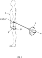
- the present method allows the estimation of the movement of an object 1 moving in an ambient magnetic field (typically the terrestrial magnetic field, where appropriate slightly altered by nearby metallic objects), noted B .
- the magnetic field is a vector field in this case three-dimensional, that is to say associating a three-dimensional vector with each three-dimensional point in which the object is mobile.
- This object 1 can be any mobile object whose position knowledge is desired, for example a wheeled vehicle, a drone, etc., but also a person or a part of that person's body (his hands, his body). head, etc.).
- the object 1 is equipped with magnetic measuring means 20, which are magnetometers and / or gradiometers. More precisely, instead of measuring the value of the components of the magnetic field B the latter directly measured the value of the components of the gradient of the magnetic field B , ie the value of the spatial derivatives.
- magnetic gradiometers 20 are known to those skilled in the art. According to certain embodiments of the invention, it is possible to use gradiometers which directly measure the value of the second derivatives (gradient of order two), and generally of i-th derivatives (gradient of order i ).
- the magnetometer (s) 20 are “axial”, ie capable of measuring a component of said magnetic field, ie the projection of said magnetic field vector B along their axis (or in the case of a gradiometer, a component of a spatial derivative of order i of said magnetic field, ie the variation of a component of ⁇ i -1 B at the level of said gradiometer along their axis).
- the magnetometers 20 are at least 3n + 3 in number, advantageously organized in groups of three in “triaxes”, ie a triplet two-by-two orthogonal magnetometers 20 associated with the same spatial position and measuring the magnetic field along the three axes.
- the orthonormal coordinate system associated with the object is chosen by convention (and for convenience for the rest of the present description) such that the triaxes are advantageously oriented in accordance with said orthonormal coordinate system, so as to further facilitate the calculations.
- the object 1 is also equipped with measuring means other than magnetic 24, in particular inertial measuring means, even if it is possible to use other types of sensors such as a camera, possibly in combination.
- measuring means other than magnetic 24 in particular inertial measuring means, even if it is possible to use other types of sensors such as a camera, possibly in combination.
- the preferred embodiment with inertial measurement means will be considered.
- Such means are widely known to those skilled in the art and typically constitute an inertial unit comprising at least one accelerometer and / or a gyrometer, preferably three accelerometers and three gyrometers, also arranged in triaxial.
- the gyrometers measure the instantaneous angular speed of the inertial unit with respect to the terrestrial reference frame, noted ⁇ .
- Accelerometers are sensitive to external forces other than gravitational applied to the sensor, and make it possible to measure a noted acceleration ⁇ .
- the magnetic and non-magnetic (inertial) measuring means 20, 24 are integral with the object 1, ie they have a substantially identical movement in the terrestrial frame of reference.
- the frame of reference of the object 1 is provided with an orthonormal Cartesian frame in which the coordinates are noted (x 1 , x 2 , x 3 ) , the magnetometers 20 thus have a predetermined position in this frame.
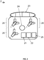
- the magnetic and non-magnetic (inertial) measurement means 20, 24 are preferably those of a box 2 as shown in Figure figure 2 presenting (for example if the object 1 is a person) means 23 for attachment to the object 1 (for example the wrist or the hand).
- These attachment means 23 consist for example of a bracelet, for example with a self-gripping strip which encloses the member and allows the integral connection. It will be understood that the invention is not not limited to estimating the movement of a person, but it is particularly advantageous in such a use because it allows a very small footprint, which is necessary for the box to be ergonomically portable by a human.
- the box 2 can comprise processing means 21 (typically a processor) for the direct implementation in real time of the processing operations of the present method, or else the measurements can be sent via communication means 25 to an external device such as a mobile terminal (smartphone) 3, or even a remote server 4, or the measurements can be recorded in local data storage means 22 (a memory for example of the flash type) local memory for a posteriori processing for example on the server 4.
- processing means 21 typically a processor
- the measurements can be sent via communication means 25 to an external device such as a mobile terminal (smartphone) 3, or even a remote server 4, or the measurements can be recorded in local data storage means 22 (a memory for example of the flash type) local memory for a posteriori processing for example on the server 4.
- the communication means 25 can implement short-range wireless communication, for example Bluetooth or Wifi (in particular in one embodiment with a mobile terminal 3) or even be means of connection to a mobile network (typically UMTS / LTE ) for long distance communication. It should be noted that the communication means 25 can be, for example, a wired connection (typically USB) for transferring data from the local data storage means 22 to those of a mobile terminal 3 or of a server 4.
- short-range wireless communication for example Bluetooth or Wifi (in particular in one embodiment with a mobile terminal 3) or even be means of connection to a mobile network (typically UMTS / LTE ) for long distance communication.
- a mobile network typically UMTS / LTE
- the communication means 25 can be, for example, a wired connection (typically USB) for transferring data from the local data storage means 22 to those of a mobile terminal 3 or of a server 4.
- a mobile terminal 3 (respectively a server 4) which hosts the “intelligence”, it comprises processing means 31 (respectively 41) such as a processor for implementing the processing operations of the present method which go be described.
- processing means 31 such as a processor for implementing the processing operations of the present method which go be described.
- the processing means used are those 21 of the box 2, the latter can also include communication means 25 for transmitting the estimated position.
- the position of the wearer can be sent to the mobile terminal 3 to display the position in an interface of a navigation software.
- the data processing means 21, 31, 41 respectively of the box 2, of a smartphone 3 and of a remote server 4 can indifferently and depending on the applications perform all or part of the process steps.
- the data processing means 21, 31, 41 evaluate the stationary character or not of the magnetic field at the level of the magnetic measuring means 20. As explained, it is simply a question of detecting whether one is in the presence of magnetic disturbance or not, without seek to correct them.
- the stationary character is representative of the relevance of the magnetic model.
- This step (b) sees the calculation of a parameter (either Boolean, or with a discrete or continuous numerical value) representative of the stationary character or not of the magnetic field.
- said parameter representative of the stationary character or not is a physical quantity with a numerical value (it is for example possible to calculate an order of magnitude of ⁇ B ⁇ t , other preferred examples will be given below), where appropriate “treated” (in step (c) or directly in step (b)) and in particular compared with one or more reference thresholds.
- a “raw” parameter we will speak of a “raw” parameter and, where appropriate, of a “processed” parameter if step (b) comprises the application of any function such as a thresholding on the value of the parameter, but we can use them indifferently in step (c).
- step (b) comprises the application of any function such as a thresholding on the value of the parameter, but we can use them indifferently in step (c).
- the present invention is not limited to any type of parameter in particular and no way of manipulating it.
- a person skilled in the art can choose any scale of his choice, for example dividing the above value by k so that the parameter processed is a rate with a value in the interval [0; 1].
- the raw value being able to be used as it is as a parameter representative of the stationary character or not of the magnetic field.
- ⁇ B ⁇ t the raw value being able to be used as it is as a parameter representative of the stationary character or not of the magnetic field.
- the data processing means 21, 31, 41 estimate at least one component of the movement of the object 1, in particular all the components of the linear speed V.
- One or more components of the angular velocity vector ⁇ can also be estimated or at least verified.
- the estimated component (s) could be the components of the position, and / or of the orientation, depending on the applications sought.
- six components of the movement will be estimated (in particular the three components of the position and the three components of the orientation).
- the contribution of the magnetic equation (s) is variable and is subject to the relevance of the magnetic model: if the magnetic field is not evaluated sufficiently stationary, the contribution of these magnetic equations will be reduced or even removed to maintain the relevance of the overall model.
- the parameter representative of the stationary character of the magnetic field calculated in step (b) is Boolean
- the contribution is itself Boolean: either the parameter is representative of a stationary character and the magnetic equations are used, or it is representative of a non-stationary character and they are not used.
- the contribution of the at least one magnetic equation will be a function of (and possibly inversely proportional to) the value of this parameter, c 'that is to say that the contribution can be variable according to the level of stationarity, in particular the higher the parameter, the lower the contribution.
- first system making it possible to provide positioning information other than magnetic (in particular as explained a first system of at least one inertial equation, but it will be understood that it will be possible to use other equations complementary to the magnetic equations, for example equations relating to images in a case of visual navigation), and a second system of at least one magnetic equation.
- unified system is meant a system of all the equations of the first and second systems.
- dX dt f X measures , where X represents a component of the movement (as explained orientation, acceleration, speed, position, etc.) and measurements represent the data acquired by the inertial measurement means 24.
- Step (c) can advantageously be implemented via a standard filtering strategy consisting in using the sensor data (means 20, 24) to calculate an estimated state representative of the real state.
- the state obviously contains movement information
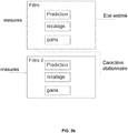
- the prediction and registration steps are classic steps of a filter implementation which use the inertial equations and the magnetic equations, and the gains are adjusted so that the filter converges.
- any state observer that is to say a filter, in particular a linear state estimator filter such as a Luenberger filter, a Kalman filter, etc., or non-linear such as an extended Kalman filter, an invariant observer, etc.
- a linear state estimator filter such as a Luenberger filter, a Kalman filter, etc.
- non-linear such as an extended Kalman filter, an invariant observer, etc.
- EKF extended Kalman filter
- the state is represented by a vector, for example of dimension n which includes the orientation and the position. It is possible to add other states to this vector to improve the estimation, for example through the sensors.
- a covariance matrix is used to estimate the covariance between each state of the filter, it is of dimension n 2 .
- the Kalman filter is performed in two steps, a prediction step and an update step. During the update, gains are then automatically adjusted as a function of the covariance, dynamic and measurement matrices (alternatively, we can build a nonlinear observer whose gains are adjusted manually).
- the updating of the covariance matrix is based on the assumption that the errors due to the sensors and to the approximations are modeled for example as a Gaussian distribution noise.
- step (b) of calculating the parameter representative of the stationary character or not of the magnetic field at the level of the means of magnetic measurement 20 is also obtained by filtering, generally simultaneously with the estimation of the movement of the object 1 (ie steps (b) and (c) are simultaneous, and more precisely implemented concomitantly over time: the The stationary nature of the magnetic field is evaluated over time, which also makes it possible to detect the appearance of disturbances as well as their disappearance. It will be understood that, alternatively, checks can be made periodically).
- step (b) preferably comprises the calculation of the innovation of a state observer (again in particular a linear state estimator filter such as a Luenberger filter, a Kalman filter, etc. ., or non-linear such as an extended Kalman filter, an invariant observer, etc.), said parameter representative of the stationary character or not of the magnetic field at the level of the magnetic measuring means 20 being a function of the innovation.
- a state observer a linear state estimator filter such as a Luenberger filter, a Kalman filter, etc. ., or non-linear such as an extended Kalman filter, an invariant observer, etc.
- the innovation of a measurement in a state observer is representative of the consistency of this measurement with the filtering model. It can therefore be used to detect the presence of magnetic disturbances and therefore of non-stationarity (which can be translated by the fact that the magnetic equation is not in agreement with the magnetic measurements).
- the observer used for step (c) is simply used.
- a single filter with two outputs the estimated state and the parameter representative of the stationary character or not of the magnetic field at the level of the magnetic measuring means 20, based on the innovation of the observer. It is during the registration step that the observer provides the innovation.
- ⁇ [ k ] (1 - ⁇ ) ⁇ [ k - 1] + a ⁇ [ k ] ⁇ [ k ] T
- ⁇ [ k ] is the innovation vector at iteration k (so that ⁇ [ k ] ⁇ [ k ] T is the innovation covariance)
- S [k] is the filtered estimate of the innovation covariance at iteration k
- 0 ⁇ ⁇ ⁇ 1 is a tuning parameter of the filter cutoff frequency.
- the covariance of the theoretical innovation is an output of the Kalman filtering in discrete time: if we denote by P [ k
- k - 1] the covariance of the predicted state error, R [ k ] the matrix of measurement noise covariance and H [ k ] the Jacobian matrix of the measurement function with respect to the state, then: S k R k + H k P k
- step (b) comprises the use of a dedicated state observer. It is in fact possible to construct a state observer based on the same equations or a small part of the same equations having the sole purpose of calculating information on the relevance of the magnetic model. We can thus use for example the filter presented in the document “Combining Inertial Measurements and Distributed Magnetometry for Motion Estimation”, Eric Dorveaux, Thomas Boudot, Mathieu Hillion, Nicolas Petit, 2011 American Control Conference on O'Farrell Street, San Francisco, CA, USA (which contains only part of the inertial equations), or a more complete filter.
- This state observer makes the hypothesis of the stationarity of the magnetic field, and we again use the innovation of this state observer to evaluate this hypothesis and deduce from it the relevance of the magnetic model (see figure 3b ).
- the use of the second system of equations is completely eliminated (i.e. the unified system is reduced to the first system) for the time of the disturbance, to cancel its impact. To do this, it suffices to no longer use these magnetic equations in step (c) if the parameter representative of the stationary nature of the magnetic field is characteristic of non-stationarity (i.e. value above a predetermined threshold).
- the gain of the state observer which performs the estimation of the movement is adapted in step (c).
- the state observer is a linear Kalman filter or an extended Kalman filter whose state contains the magnetic field B, this requires a modification of the dynamic noise matrix of the magnetic equation.
- a third embodiment consists in making the adjustment gain K linked to the magnetic equations originating from a Kalman filter (or from any linear filter) inversely proportional to the parameter representative of the stationary or non-stationary nature of the magnetic field.
- the more relevant the model ie the more the parameter representative of the stationary nature of the magnetic field is close to zero), the stronger the adjustment gain.
- the invention relates in particular to the equipment 2, 3, 4 for implementing one or other of the embodiments of the method.
- the equipment is an autonomous box 2 comprising the magnetic measuring means 20, the measuring means other than magnetic (inertial) 24, and the data processing means 21 configured for setting. implementation of the process steps.
- the box 2 further comprises attachment means 23 of the box 2, and where appropriate data storage means 22 (for storing, for example, estimated movements) and / or communication means 25 for exporting data. results.
- the equipment is a mobile terminal 3 or a server 4, suitable for communicating with a box 2 comprising the magnetic and non-magnetic measuring means 20, 24.
- the terminal 3 or the server 4 comprises the processing means 31 or 41 configured for the implementation of the steps of the method.
- Each box 2 can still include data processing means 21 for controlling the means 20, 24 and the transmission (via communication means 25) of the measured data to the data processing means 31, 41.
- the invention also relates to the system comprising the equipment 3, 4 according to this embodiment and the “satellite” box (s) 2 in connection.
- the invention relates to a computer program product comprising code instructions for the execution (on the processing means 21, 31, 41) of a method for estimating the movement. of an object 1 moving in an ambient magnetic field according to the first aspect of the invention, as well as storage means readable by computer equipment (for example data storage means 22) on which there is this program product d 'computer.
Description
La présente invention concerne le domaine de la navigation sans GPS.The present invention relates to the field of navigation without GPS.
Plus précisément, elle concerne un procédé d'estimation du mouvement d'un objet par des techniques magnéto-inertielles.More precisely, it relates to a method for estimating the movement of an object by magneto-inertial techniques.
Les techniques dites de navigation magnéto-inertielles permettent d'estimer précisément la vitesse (et de là la position par intégration) d'un solide dans un lieu où le champ magnétique est perturbé.So-called magneto-inertial navigation techniques make it possible to precisely estimate the speed (and hence the position by integration) of a solid in a place where the magnetic field is disturbed.
Précisément, il a été proposé dans le brevet
Grâce à cette information sur la vitesse du solide, l'erreur sur l'estimation de position sera dans le pire des cas proportionnelle au temps, contrairement aux techniques inertielles classiques où elle est quadratique en temps.Thanks to this information on the speed of the solid, the error on the position estimate will in the worst case be proportional to time, unlike conventional inertial techniques where it is quadratic in time.
Ces techniques magnéto-inertielles apportent ainsi entière satisfaction, et requièrent des capteurs inertiels de moindre performance que les méthodes inertielles classiques (basées sur l'intégration au travers d'un filtre de Kalman ou d'un autre observateur d'informations en provenance de gyromètres et d'accéléromètres embarqués sur le solide dont on souhaite estimer la position et la vitesse : typiquement, les gyromètres « maintiennent » un repère, dans lequel une double intégration temporelle des mesures des accéléromètres permet d'estimer le mouvement) et donc moins encombrants.These magneto-inertial techniques thus provide complete satisfaction, and require inertial sensors with lower performance than conventional inertial methods (based on integration through a Kalman filter or another observer of information coming from gyrometers and accelerometers on board the solid whose position and speed are to be estimated: typically, gyrometers “maintain” a reference point, in which a double temporal integration of the measurements of the accelerometers makes it possible to estimate the movement) and therefore less bulky.
Ainsi, au moins une centrale inertielle est couplée à un ou plusieurs magnétomètres répartis spatialement (typiquement magnétomètres disposés sur les sommets d'un trièdre direct) et solidaire de la centrale inertielle (typiquement placée à l'origine du trièdre). Les données issues de ces capteurs sont transmises à une carte électronique d'acquisition et de calcul qui délivre à l'utilisateur l'information de position et de vitesse par résolution de l'équation susmentionnée. L'utilisation de plusieurs magnétomètres permet de mesurer directement les gradients de champ magnétique par exemple par différence finie (développement de Taylor), au lieu de les estimer.Thus, at least one inertial unit is coupled to one or more spatially distributed magnetometers (typically magnetometers arranged on the vertices of a direct trihedron) and integral with the inertial unit (typically placed at the origin of the trihedron). The data from these sensors are transmitted to an electronic acquisition and calculation card which delivers the position and speed information to the user by solving the aforementioned equation. The use of several magnetometers makes it possible to directly measure the magnetic field gradients, for example by finite difference (Taylor development), instead of estimating them.
Cependant, l'équation Ḃ = -Ω ∧ B + ∇B. V n'est vraiment valide que dans l'hypothèse d'un champ magnétique ambiant stationnaire. Plus précisément, elle présente en réalité un terme supplémentaire ![]()
![]()
Ce n'est par exemple pas le cas lorsqu'un objet métallique se déplace à proximité. En présence d'une telle perturbation magnétique (le champ magnétique devient non stationnaire), le modèle du comportement magnétique supposant que ![]()
![]()
Pour résoudre cette difficulté, il a été proposé de poursuivre l'effort de modélisation pour inclure les perturbations magnétiques dans le modèle, c'est-à-dire l'ensemble des équations considérées.To resolve this difficulty, it has been proposed to continue the modeling effort to include the magnetic disturbances in the model, that is to say all the equations considered.
En particulier, il a été présenté dans le document
L'équation précédente est vraie en toutes circonstances, mais présente l'inconvénient de nécessiter des capteurs permettant de mesurer le champ électrique.The preceding equation is true in all circumstances, but has the drawback of requiring sensors making it possible to measure the electric field.
Alternativement, il a été proposé de modéliser une partie seulement des perturbations magnétiques. C'est le cas de la modélisation des perturbations magnétiques liées au réseau de distribution d'électricité (voir document
Enfin, il est connu du document
De telles techniques de modélisation d'une partie connue des perturbations apportent satisfaction, mais ne sont efficaces que contre un certain nombre de perturbations prédéfinies. Elles ne permettent pas de prendre en compte les perturbations inattendues par exemple liées au déplacement d'objets métalliques de formes diverses.Such techniques for modeling a known part of the disturbances are satisfactory, but are only effective against a certain number of predefined disturbances. They do not make it possible to take into account unexpected disturbances, for example linked to the movement of metal objects of various shapes.
Il serait souhaitable de disposer d'une nouvelle méthode de navigation magnéto-inertielle par mesure du gradient du champ magnétique qui puisse traiter de façon universelle et efficace toutes les perturbations magnétiques, et ne nécessitant pas de capteurs additionnels.It would be desirable to have a new method of magneto-inertial navigation by measuring the gradient of the magnetic field which can deal universally and efficiently with all magnetic disturbances, and which does not require additional sensors.
La présente invention se rapporte ainsi selon un premier aspect à un procédé d'estimation du mouvement d'un objet évoluant dans un champ magnétique ambiant, le procédé étant caractérisé en ce qu'il comprend des étapes de :
- (a) Acquisition :
- ∘ par des moyens de mesure magnétique solidaires dudit objet, d'au moins une composante du champ magnétique et/ou d'une dérivée i-ième du champ magnétique, au niveau des moyens de mesure magnétique ;
- ∘ par des moyens de mesure autre que magnétique solidaires dudit objet, d'au moins une information représentative du mouvement de l'objet ;
- (b) Evaluation par des moyens de traitement de données du caractère stationnaire ou non du champ magnétique au niveau des moyens de mesure magnétique ;
- (c) Estimation par les moyens de traitement de données d'au moins une composante du mouvement dudit objet en utilisant,
- ∘ au moins une équation autre que magnétique liant ladite composante du mouvement dudit objet et l'au moins une information acquise représentative du mouvement de l'objet ;
- ∘ selon le résultat de ladite évaluation du caractère stationnaire ou non du champ magnétique au niveau des moyens de mesure magnétique, au moins une équation magnétique liant ladite composante du mouvement dudit objet et l'au moins une composante acquise du champ magnétique et/ou d'une dérivée i-ième du champ magnétique.
- (a) Acquisition:
- ∘ by magnetic measuring means integral with said object, at least one component of the magnetic field and / or an i-th derivative the magnetic field, at the level of the magnetic measuring means;
- ∘ by measuring means other than magnetic integral with said object, at least one item of information representative of the movement of the object;
- (b) Evaluation by data processing means of the stationary character or not of the magnetic field at the level of the magnetic measuring means;
- (c) Estimation by the data processing means of at least one component of the movement of said object using,
- ∘ at least one equation other than magnetic linking said component of the movement of said object and at least one acquired item of information representative of the movement of the object;
- ∘ according to the result of said evaluation of the stationary character or not of the magnetic field at the level of the magnetic measuring means, at least one magnetic equation linking said component of the movement of said object and at least one acquired component of the magnetic field and / or d 'an i-th derivative of the magnetic field.
Selon d'autres caractéristiques avantageuses et non limitatives :
- les moyens de mesure magnétique comprennent une pluralité de gradiomètres et/ou magnétomètres organisés en triaxes, chaque triaxe étant associé à une position spatiale ;
- la ou les équations magnétiques sont de la forme

- l'équation magnétique est Ḃ = -Ω × B + ∇B·V ;
- lesdits moyens de mesure autre que magnétique sont des moyens de mesure inertielle, de sorte que ladite information acquise représentative du mouvement de l'objet est au moins une composante d'une accélération et/ou d'une vitesse angulaire de l'objet ;
- ladite au moins une équation autre que magnétique est une équation inertielle liant ladite composante du mouvement dudit objet et l'au moins une composante acquise d'une accélération et/ou d'une vitesse angulaire de l'objet ;
- l'étape (a) comprend l'acquisition par les moyens de mesure inertielle de trois composantes de l'accélération de l'objet et trois composantes de la vitesse angulaire de l'objet ;
- l'étape (b) comprend le calcul d'un paramètre représentatif du caractère stationnaire ou non du champ magnétique au niveau des moyens de mesure magnétique, la contribution de l'au moins une équation magnétique dans l'étape (c) étant fonction dudit paramètre représentatif du caractère stationnaire ou non du champ magnétique au niveau des moyens de mesure magnétique ;
- l'étape (b) comprend le calcul de l'innovation d'un observateur d'état, ledit paramètre représentatif du caractère stationnaire ou non du champ magnétique au niveau des moyens de mesure magnétique étant fonction de ladite innovation ;
- ledit paramètre représentatif du caractère stationnaire ou non du champ magnétique au niveau des moyens de mesure magnétique est la différence entre la trace de la matrice théorique de la covariance de l'innovation, et la trace de la matrice estimée de la covariance de l'innovation ;
- l'étape (c) comprend la mise en œuvre d'un observateur d'état pour estimer un état comprenant ladite au moins une composante du mouvement dudit objet, la contribution de ladite au moins une équation magnétique étant contrôlée via un gain dudit observateur d'état ;
- l'observateur d'état mis en œuvre à l'étape (c) est l'observateur d'état utilisé à l'étape (b).
- the magnetic measuring means comprise a plurality of gradiometers and / or magnetometers organized in triaxes, each triaxis being associated with a spatial position;
- the magnetic equation (s) are of the form
- the magnetic equation is Ḃ = -Ω × B + ∇B · V ;
- said measuring means other than magnetic are inertial measuring means, so that said acquired information representative of the movement of the object is at least one component of an acceleration and / or an angular speed of the object;
- said at least one equation other than magnetic is an inertial equation linking said component of the movement of said object and the at least one component acquired from an acceleration and / or an angular speed of the object;
- step (a) comprises the acquisition by the inertial measurement means of three components of the acceleration of the object and three components of the angular speed of the object;
- step (b) comprises the calculation of a parameter representative of the stationary or non-stationary nature of the magnetic field at the level of the magnetic measuring means, the contribution of the at least one magnetic equation in step (c) being a function of said parameter representative of the stationary or non-stationary character of the magnetic field at the level of the magnetic measuring means;
- step (b) comprises calculating the innovation of a state observer, said parameter representative of the stationary or non-stationary nature of the magnetic field at the level of the magnetic measuring means being a function of said innovation;
- said parameter representative of the stationary or non-stationary nature of the magnetic field at the level of the magnetic measurement means is the difference between the trace of the theoretical matrix of the innovation covariance, and the trace of the estimated matrix of the innovation covariance ;
- step (c) comprises implementing a state observer to estimate a state comprising said at least one component of the movement of said object, the contribution of said at least one magnetic equation being controlled via a gain of said observer d 'state;
- the state observer implemented in step (c) is the state observer used in step (b).
Selon un deuxième aspect, l'invention concerne un équipement d'estimation du mouvement d'un objet évoluant dans un champ magnétique ambiant, caractérisé en ce qu'il comprend des moyens de traitement de données configurés pour mettre en œuvre :
- Un module de réception :
- ∘ d'au moins une composante du champ magnétique et/ou d'une dérivée i-ième du champ magnétique, acquise par des moyens de mesure magnétique solidaires dudit objet,
- ∘ d'au moins une composante d'une information représentative du mouvement de l'objet, acquise par des moyens de mesure autre que magnétique solidaires dudit objet,
- un module d'évaluation du caractère stationnaire ou non du champ magnétique au niveau des moyens de mesure magnétique ;
- un module d'estimation d'au moins une composante du mouvement dudit objet en utilisant,
- ∘ au moins une équation autre que magnétique liant ladite composante du mouvement dudit objet et l'au moins une information acquise représentative du mouvement de l'objet ;
- ∘ selon le résultat de ladite évaluation du caractère stationnaire ou non du champ magnétique au niveau des moyens de mesure magnétique, au moins une équation magnétique liant ladite composante du mouvement dudit objet et l'au moins une composante acquise du champ magnétique et/ou d'une dérivée i-ième du champ magnétique.
- A reception module:
- ∘ at least one component of the magnetic field and / or of an i-th derivative of the magnetic field, acquired by magnetic measuring means integral with said object,
- ∘ at least one component of information representative of the movement of the object, acquired by measuring means other than magnetic integral with said object,
- a module for evaluating the stationary or non-stationary nature of the magnetic field at the level of the magnetic measuring means;
- a module for estimating at least one component of the movement of said object using,
- ∘ at least one equation other than magnetic linking said component of the movement of said object and at least one acquired item of information representative of the movement of the object;
- ∘ according to the result of said evaluation of the stationary character or not of the magnetic field at the level of the magnetic measuring means, at least one magnetic equation linking said component of the movement of said object and at least one acquired component of the magnetic field and / or d 'an i-th derivative of the magnetic field.
Selon d'autres caractéristiques avantageuses et non limitatives :
- L'équipement est un boitier comprenant les moyens de mesure magnétique et les moyens de mesure autre que magnétique ;
- L'équipement est un terminal mobile ou un serveur, adapté pour communiquer avec un boitier comprenant les moyens de mesure magnétique et les moyens de mesure autre que magnétique.
- The equipment is a box comprising the magnetic measuring means and the measuring means other than magnetic;
- The equipment is a mobile terminal or a server, suitable for communicating with a box comprising the magnetic measuring means and the measuring means other than magnetic.
Selon un troisième aspect, l'invention concerne un système comprenant l'équipement selon le deuxième aspect de l'invention et au moins un boitier en connexion.According to a third aspect, the invention relates to a system comprising the equipment according to the second aspect of the invention and at least one box in connection.
Selon un quatrième et un cinquième aspect, l'invention concerne un produit programme d'ordinateur comprenant des instructions de code pour l'exécution d'un procédé d'estimation du mouvement d'un objet évoluant dans un champ magnétique ambiant selon le premier aspect de l'invention ; et un moyen de stockage lisible par un équipement informatique sur lequel un produit programme d'ordinateur comprend des instructions de code pour l'exécution d'un procédé d'estimation du mouvement d'un objet évoluant dans un champ magnétique ambiant selon le premier aspect de l'invention.According to a fourth and a fifth aspect, the invention relates to a computer program product comprising code instructions for the execution of a method for estimating the movement of an object moving in an ambient magnetic field according to the first aspect. of the invention; and a storage means readable by computer equipment on which a computer program product comprises code instructions for the execution of a method for estimating the movement of an object moving in an ambient magnetic field according to the first aspect of the invention.
D'autres caractéristiques et avantages de la présente invention apparaîtront à la lecture de la description qui va suivre d'un mode de réalisation préférentiel. Cette description sera donnée en référence aux dessins annexés dans lesquels :
- la
figure 1 est un schéma d'équipements pour la mise en œuvre du procédé selon l'invention ; - La
figure 2 représente plus en détail un exemple de boitier pour la mise en œuvre du procédé selon l'invention ; - Les
figures 3a et3b représentent divers observateur d'états utilisés dans des modes de réalisation du procédé selon l'invention.
- the
figure 1 is a diagram of equipment for implementing the method according to the invention; - The
figure 2 shows in more detail an example of a box for implementing the method according to the invention; - The
figures 3a and3b represent various state observers used in embodiments of the method according to the invention.
Le présent procédé propose, plutôt que de combiner les deux types de modèles (inertiel et magnétique) en un seul modèle, d'utiliser des techniques de filtrage adaptatif permettant de modifier l'impact de l'équation magnétique dans le modèle de filtrage global. Plus précisément, on garde l'équation magnétique « simplifiée » Ḃ = -Ω ∧ B + ∇B.V (ou tout autre dérivée de cette équation, de la forme ![]()
![]()
On utilise pour cela comme l'on verra un critère permettant de :
- détecter que le système est en présence d'une perturbation magnétique et ainsi réduire l'impact de la ou les équations magnétiques dans le modèle, et
- détecter la fin de la perturbation magnétique et ainsi ré-augmenter l'impact de la ou les équations magnétiques.
- detect that the system is in the presence of a magnetic disturbance and thus reduce the impact of the magnetic equation (s) in the model, and
- detect the end of the magnetic disturbance and thus re-increase the impact of the magnetic equation (s).
En référence à la
Cet objet 1 peut être n'importe quel objet mobile dont la connaissance de la position est souhaitée, par exemple un véhicule à roues, un drone, etc., mais également une personne ou une partie du corps de cette personne (ses mains, sa tête, etc.).This
L'objet 1 est équipé de moyens de mesure magnétique 20, qui sont des magnétomètres et/ou des gradiomètres. Plus précisément, au lieu de mesurer la valeur des composantes du champ magnétique
Dans la suite de la description on prendra l'exemple de magnétomètres mais l'homme du métier saura transposer à des gradiomètres.In the remainder of the description, the example of magnetometers will be taken, but those skilled in the art will know how to transpose to gradiometers.
Le ou les magnétomètres 20 sont « axiaux », c'est à dire capables de mesurer une composante dudit champ magnétique, i.e. la projection dudit vecteur champ magnétique
Avantageusement les magnétomètres 20 sont au moins au nombre de 3n+3, avantageusement organisé par groupes de trois en « triaxes », i.e. un triplet de magnétomètres 20 deux à deux orthogonaux associés à la même position spatiale et mesurant le champ magnétique selon les trois axes.Advantageously, the
De façon préférée, le repère orthonormé associé à l'objet est choisi par convention (et par facilité pour la suite de la présente description) tel que les triaxes sont avantageusement orientés conformément audit repère orthonormé, de sorte à faciliter encore les calculs.Preferably, the orthonormal coordinate system associated with the object is chosen by convention (and for convenience for the rest of the present description) such that the triaxes are advantageously oriented in accordance with said orthonormal coordinate system, so as to further facilitate the calculations.
Mais l'homme du métier saura dans tous les cas transposer à n'importe quelle disposition spatiale de gradiomètres/magnétomètres.But those skilled in the art will in all cases be able to transpose to any spatial arrangement of gradiometers / magnetometers.
L'objet 1 est également équipé de moyens de mesure autre que magnétique 24, en particulier des moyens de mesure inertielle, même si on pourra utiliser d'autres types de capteurs tels qu'une caméra, éventuellement en combinaison. Dans la suite de la description on considèrera le mode de réalisation préféré avec des moyens de mesure inertielle.The
De tels moyens sont largement connus de l'homme du métier et constituent typiquement une centrale à inertie comprenant au moins un accéléromètre et/ou un gyromètre, de façon préférée trois accéléromètres et trois gyromètres, également disposés en triaxe. Les gyromètres mesurent la vitesse angulaire instantanée de la centrale inertielle par rapport au référentiel terrestre, notée
Les moyens de mesure magnétique et non-magnétique (inertielle) 20, 24 sont solidaires de l'objet 1, i.e. ils présentent un mouvement sensiblement identique dans le référentiel terrestre. De façon préférée, le référentiel de l'objet 1 est muni d'un repère cartésien orthonormé dans lequel les coordonnées sont notées (x 1,x 2 ,x 3), les magnétomètres 20 présentent ainsi une position prédéterminée dans ce repère.The magnetic and non-magnetic (inertial) measuring means 20, 24 are integral with the
Les moyens de mesure magnétique et non-magnétique (inertielle) 20, 24 sont préférentiellement ceux d'un boitier 2 tel que représenté sur la
Le boitier 2 peut comprendre des moyens de traitement 21 (typiquement un processeur) pour la mise en œuvre directement en temps réel des traitements du présent procédé, ou bien les mesures peuvent être émises via des moyens de communication 25 vers un dispositif externe tel qu'un terminal mobile (smartphone) 3, voire un serveur distant 4, ou encore les mesures peuvent être enregistrées dans des moyens de stockage de données 22 locaux (une mémoire par exemple de type flash) mémoire locale pour un traitement a posteriori par exemple sur le serveur 4.The
Les moyens de communication 25 peuvent mettre en œuvre une communication sans fil à courte portée par exemple Bluetooth ou Wifi (en particulier dans un mode de réalisation avec un terminal mobile 3) voire être des moyens de connexion à un réseau mobile (typiquement UMTS/LTE) pour une communication à longue distance. Il est à noter que les moyens de communication 25 peuvent être par exemple une connectique filaire (typiquement USB) pour transférer les données des moyens de stockage de données 22 locaux à ceux d'un terminal mobile 3 ou d'un serveur 4.The communication means 25 can implement short-range wireless communication, for example Bluetooth or Wifi (in particular in one embodiment with a mobile terminal 3) or even be means of connection to a mobile network (typically UMTS / LTE ) for long distance communication. It should be noted that the communication means 25 can be, for example, a wired connection (typically USB) for transferring data from the local data storage means 22 to those of a
Si c'est un terminal mobile 3 (respectivement un serveur 4) qui héberge « l'intelligence », il comprend des moyens de traitement 31 (respectivement 41) tels qu'un processeur pour la mise en œuvre des traitements du présent procédé qui vont être décrits. Lorsque les moyens de traitement utilisés sont ceux 21 du boitier 2, celui-ci peut encore inclure des moyens de communication 25 pour transmettre la position estimée. Par exemple la position du porteur peut être envoyée au terminal mobile 3 pour afficher la position dans une interface d'un logiciel de navigation.If it is a mobile terminal 3 (respectively a server 4) which hosts the “intelligence”, it comprises processing means 31 (respectively 41) such as a processor for implementing the processing operations of the present method which go be described. When the processing means used are those 21 of the
Dans la suite de la présente description, on verra que les moyens de traitement de données 21, 31, 41 respectivement du boitier 2, d'un smartphone 3 et d'un serveur distant 4 peuvent indifféremment et selon les applications réaliser tout ou partie des étapes du procédé.In the remainder of the present description, it will be seen that the data processing means 21, 31, 41 respectively of the
Dans une première étape (a), le procédé comprend l'acquisition (en particulier dans un référentiel de l'objet 1) de deux types de données :
- par les moyens de mesure magnétique 20 (le ou les gradiomètres/magnétomètres) solidaires dudit objet 1, d'une composante :
- ∘ du champ magnétique et/ou
- ∘ d'au moins une dérivée i-ième dudit champ magnétique
B , avec une ou plusieurs valeurs i > 1 (comme expliqué, divers gradiomètres/magnétomètres peuvent être utilisés de sorte à mesurer divers ordres des dérivées ou directement les valeurs du champ magnétique).
- par les moyens de mesure autre que magnétique (24) solidaires dudit objet 1 :
- ∘ d'au moins une information représentative du mouvement de l'objet. On comprendra que cette information peut être de nombreux types : données inertielles, images, informations de profondeur, etc.
- by the magnetic measuring means 20 (one or more gradiometers / magnetometers) secured to said
object 1, of a component:- ∘ of the magnetic field and / or
- ∘ at least one i-th derivative of said magnetic field
B , with one or more values i > 1 (as explained, various gradiometers / magnetometers can be used so as to measure various orders of the derivatives or directly the values of the magnetic field).
- by measuring means other than magnetic (24) secured to said object 1:
- ∘ at least one piece of information representative of the movement of the object. It will be understood that this information can be of many types: inertial data, images, depth information, etc.
En particulier, dans le cas préféré inertiel on a l'acquisition :
- par les moyens de mesure inertielle 24 solidaires dudit objet 1, d'au moins une composante :
- ∘ de l'accélération et/ou
- ∘ de la vitesse angulaire de l'objet 1 (préférentiellement trois composantes de la vitesse angulaire, et trois composantes de l'accélération).
- by the inertial measurement means 24 integral with said
object 1, of at least one component:- ∘ acceleration and / or
- ∘ of the angular speed of the object 1 (preferably three components of the angular speed, and three components of the acceleration).
Ces grandeurs sont avantageusement mesurées avec un échantillonnage dt (i.e. toutes les « dt » secondes) avec dt très petit devant le temps caractéristique des mouvements de l'objet 1, typiquement 40 ms.These quantities are advantageously measured with a sampling dt (i.e. every “dt” seconds) with dt very small compared to the characteristic time of the movements of the
Dans une étape (b), les moyens de traitement de données 21, 31, 41 évaluent le caractère stationnaire ou non du champ magnétique au niveau des moyens de mesure magnétique 20. Comme expliqué il s'agit simplement de détecter si l'on est en présence de perturbation magnétiques ou pas, sans chercher à les corriger. Le caractère stationnaire est représentatif de la pertinence du modèle magnétique.In a step (b), the data processing means 21, 31, 41 evaluate the stationary character or not of the magnetic field at the level of the magnetic measuring means 20. As explained, it is simply a question of detecting whether one is in the presence of magnetic disturbance or not, without seek to correct them. The stationary character is representative of the relevance of the magnetic model.
Cette étape (b) voit le calcul d'un paramètre (soit booléen, soit à valeur numérique discrète ou continue) représentatif du caractère stationnaire ou non du champ magnétique.This step (b) sees the calculation of a parameter (either Boolean, or with a discrete or continuous numerical value) representative of the stationary character or not of the magnetic field.
Dans un premier mode de réalisation, on peut directement obtenir une information booléenne, par exemple avec un capteur magnétique dédié présentant un seuil de sensibilité prédéterminé.In a first embodiment, it is possible to obtain Boolean information directly, for example with a dedicated magnetic sensor having a predetermined sensitivity threshold.
Dans un deuxième mode de réalisation, ledit paramètre représentatif du caractère stationnaire ou non est une quantité physique à valeur numérique (on peut par exemple calculer un ordre de grandeur de ![]()
![]()
Plus précisément, s'il y a un unique seuil, on revient à un paramètre booléen : soit le champ magnétique est suffisamment stationnaire (le seuil n'est pas dépassé) pour que le modèle magnétique soit pertinent, soit il ne l'est pas suffisamment (le seuil est dépassé) et alors le modèle magnétique n'est plus pertinent. S'il y a plusieurs seuils, on obtient des valeurs discrètes, et le paramètre traité constitue une sorte de « niveau de stationnarité ». Par exemple on peut avoir k seuils croissants (numérotés de 1 à k, k ≥ 2), et k+1 valeurs de paramètre traité :
- si la valeur du paramètre brut est en-dessous du premier seuil, le paramètre traité a pour valeur « 0 » (i.e. la stationnarité est maximale) ;
- si la valeur du paramètre brut est au-dessus du k-ième seuil, le paramètre traité a pour valeur « k » (i.e. la stationnarité est minimale - les perturbations sont maximales) ;
- de la valeur du paramètre brut est entre le i-ème seuil et le i+1-ième seuil

- if the value of the raw parameter is below the first threshold, the processed parameter has the value “ 0 ” (ie the stationarity is maximum);
- if the value of the raw parameter is above the k-th threshold, the processed parameter has the value “ k ” (ie the stationarity is minimum - the disturbances are maximum);
- of the raw parameter value is between the i-th threshold and the i + 1-th threshold
Au lieu d'avoir un paramètre à valeur dans ![]()
![]()
On note qu'il n'y a pas forcément de seuillage, la valeur brute pouvant être utilisée telle quelle comme paramètre représentatif du caractère stationnaire ou non du champ magnétique. Comme expliqué avant on peut chercher directement à évaluer un ordre de grandeur de ![]()
![]()
L'homme du métier saura réaliser une telle évaluation, mais on décrira plus loin des techniques très avantageuses dans le cadre de la présente invention.Those skilled in the art will know how to carry out such an evaluation, but very advantageous techniques will be described later in the context of the present invention.
De façon arbitraire (comme présenté ci-avant, et on verra que cela coïncide avec les exemples qui seront présentés), lorsque le paramètre est à valeur numérique, on peut décider que plus la valeur dudit paramètre est proche de zéro, plus le champ magnétique a un caractère stationnaire, mais on pourra tout à fait prévoir l'inverse.Arbitrarily (as presented above, and we will see that this coincides with the examples which will be presented), when the parameter has a numerical value, we can decide that the more the value of said parameter is close to zero, the more the magnetic field has a stationary character, but it is quite possible to predict the reverse.
Dans une étape (c), les moyens de traitement de données 21, 31, 41 estiment au moins une composante du mouvement de l'objet 1, en particulier toutes les composantes de la vitesse linéaire V. Une ou plusieurs composantes du vecteur vitesse angulaire Ω peuvent être également estimées ou du moins vérifiées. Alternativement, la ou les composantes estimées pourront être les composantes de la position, et/ou de l'orientation, selon les applications recherchées. De façon préférée, six composantes du mouvement seront estimées (en particulier les trois composantes de la position et les trois composantes de l'orientation).In a step (c), the data processing means 21, 31, 41 estimate at least one component of the movement of the
Cette estimation est faite en utilisant :
- ∘ au moins une équation autre que magnétique (i.e. ne liant pas des composantes du champ magnétique ou d'une de ses dérivées) liant ladite composante du mouvement dudit objet 1 et l'au moins une information acquise représentative du mouvement de l'objet (c'est-à-dire en particulier au moins une équation inertielle liant ladite composante du mouvement dudit objet 1 et l'au moins une composante acquise d'une accélération et/ou d'une vitesse angulaire de l'objet 1) ;
- ∘ selon la valeur calculée du paramètre représentatif du caractère stationnaire ou non du champ magnétique au niveau des moyens de mesure magnétique 20, au moins une équation magnétique liant ladite composante du mouvement dudit objet 1 et l'au moins une composante acquise du champ magnétique et/ou d'une dérivée i-ième du champ magnétique.
- ∘ at least one equation other than magnetic (ie not linking components of the magnetic field or one of its derivatives) linking said component of the movement of said
object 1 and at least one acquired item of information representative of the movement of the object ( that is to say in particular at least one inertial equation linking said component of the movement of saidobject 1 and at least one component acquired from an acceleration and / or an angular speed of the object 1); - ∘ according to the calculated value of the parameter representative of the stationary character or not of the magnetic field at the level of the magnetic measuring means 20, at least one magnetic equation linking said component of the movement of said
object 1 and at least one acquired component of the magnetic field and / or an i-th derivative of the magnetic field.
Plus précisément, la contribution de la ou des équation(s) magnétique(s) est variable et est subordonnée à la pertinence du modèle magnétique : si le champ magnétique n'est pas évalué suffisamment stationnaire, la contribution de ces équations magnétiques sera diminuée voire supprimée pour conserver la pertinence du modèle global.More precisely, the contribution of the magnetic equation (s) is variable and is subject to the relevance of the magnetic model: if the magnetic field is not evaluated sufficiently stationary, the contribution of these magnetic equations will be reduced or even removed to maintain the relevance of the overall model.
Si le paramètre représentatif du caractère stationnaire du champ magnétique calculé à l'étape (b) est booléen, la contribution est elle-même booléenne : soit le paramètre est représentatif d'un caractère stationnaire est on utilise les équations magnétiques, soit il est représentatif d'un caractère non-stationnaire et on ne les utilise pas.If the parameter representative of the stationary character of the magnetic field calculated in step (b) is Boolean, the contribution is itself Boolean: either the parameter is representative of a stationary character and the magnetic equations are used, or it is representative of a non-stationary character and they are not used.
Si le paramètre représentatif du caractère stationnaire du champ magnétique calculé à l'étape (b) est à valeur numérique, la contribution de l'au moins une équation magnétique sera fonction de (et éventuellement inversement proportionnelle à) la valeur de ce paramètre, c'est-à-dire que la contribution peut être variable selon le niveau de stationnarité, en particulier plus le paramètre est haut plus la contribution est faible. Par exemple, si l'on reprend l'exemple précédent on le paramètre présente k valeurs qui sont des taux t dans [0; 1], alors la contribution peut être donnée par la valeur (1-t) ; si t=0 (niveau de stationnarité maximal), les équations magnétiques sont utilisées à 100%, si t=1 (niveau de stationnarité minimal), les équations magnétiques sont utilisées à 0% (i.e. supprimées).If the parameter representative of the stationary character of the magnetic field calculated in step (b) has a numerical value, the contribution of the at least one magnetic equation will be a function of (and possibly inversely proportional to) the value of this parameter, c 'that is to say that the contribution can be variable according to the level of stationarity, in particular the higher the parameter, the lower the contribution. For example, if we take the previous example again, the parameter presents k values which are rates t in [0; 1], then the contribution can be given by the value (1-t); if t = 0 (stationarity level maximum), the magnetic equations are used at 100%, if t = 1 (minimum stationarity level), the magnetic equations are used at 0% (ie suppressed).
Par commodité, on parlera d'un premier système permettant de fournir une information de positionnement autre que magnétique (en particulier comme expliqué un premier système d'au moins une équation inertielle, mais on comprendra qu'on pourra utiliser d'autres équations complémentaires des équations magnétiques, par exemple des équations portant sur des images dans un cas de navigation visuelle), et d'un deuxième système d'au moins une équation magnétique. Par « système unifié » on entendra un système de toutes les équations des premier et deuxième systèmes.For convenience, we will speak of a first system making it possible to provide positioning information other than magnetic (in particular as explained a first system of at least one inertial equation, but it will be understood that it will be possible to use other equations complementary to the magnetic equations, for example equations relating to images in a case of visual navigation), and a second system of at least one magnetic equation. By “unified system” is meant a system of all the equations of the first and second systems.
On notera que les équations de chacun des systèmes soit impliquent directement la ou les composantes du mouvement recherchées, soit leurs dérivées (par exemple la vitesse angulaire si l'on cherche l'orientation).It will be noted that the equations of each of the systems either directly imply the component (s) of the movement sought, or their derivatives (for example the angular speed if the orientation is sought).
En ce qui concerne le premier système, on a de manière générale un modèle dynamique d'une ou plusieurs équations de la forme : ![]()
![]()
Par exemple, on peut prendre le premier système 
En ce qui concerne le deuxième système, comme expliqué on peut prendre une ou plusieurs équations de la forme ![]()
![]()
On notera qu'il est toujours possible de modéliser une partie des perturbations magnétiques dans le deuxième système comme évoqué précédemment (perturbations liées au réseau de distribution d'électricité, petites perturbations magnétiques sous la forme de dipôles magnétiques, etc.) de sorte à ce que la présence de ces perturbations « gérables » ne nécessite pas de diminuer ou supprimer la contribution des équations mathématiques, i.e. que seules les perturbations « non modélisables » entrainent l'évaluation du champ magnétique comme non stationnaire.It will be noted that it is always possible to model part of the magnetic disturbances in the second system as mentioned previously (disturbances linked to the electricity distribution network, small magnetic disturbances in the form of magnetic dipoles, etc.) so as to achieve this. that the presence of these “manageable” disturbances does not require reducing or eliminating the contribution of the mathematical equations, ie that only “non-modelable” disturbances lead to the evaluation of the magnetic field as non-stationary.
L'étape (c) peut de façon avantageuse être mise en œuvre via une stratégie de filtrage standard consistant à utiliser les données capteurs (moyens 20, 24) pour calculer un état estimé représentatif de l'état réel. Dans notre cas, l'état contient bien évidemment des informations de mouvement, les étapes de prédiction et de recalage sont des étapes classiques d'une implémentation de filtre qui utilisent les équations inertielles et les équations magnétiques, et les gains sont réglés pour que le filtre converge.Step (c) can advantageously be implemented via a standard filtering strategy consisting in using the sensor data (means 20, 24) to calculate an estimated state representative of the real state. In our case, the state obviously contains movement information, the prediction and registration steps are classic steps of a filter implementation which use the inertial equations and the magnetic equations, and the gains are adjusted so that the filter converges.
Pour cela, on peut utiliser tout observateur d'état (c'est-à-dire un filtre, en particulier un filtre estimateur d'état linéaire tel qu'un filtre Luenberger, un filtre de Kalman, etc., ou non-linéaire tel qu'un filtre de Kalman étendu, un observateur invariant, etc.). Dans la présente description, on prendra l'exemple du filtre de Kalman étendu (EKF, « extended Kalman filter »), mais l'homme du métier saura transposer à d'autres filtres.For this, we can use any state observer (that is to say a filter, in particular a linear state estimator filter such as a Luenberger filter, a Kalman filter, etc., or non-linear such as an extended Kalman filter, an invariant observer, etc.). In the present description, the example of the extended Kalman filter (EKF) will be taken, but those skilled in the art will be able to transpose to other filters.
Dans un filtre de Kalman étendu, l'état est représenté par un vecteur par exemple de dimension n qui comprend l'orientation et la position. Il est possible d'ajouter d'autres états à ce vecteur pour améliorer l'estimation, par exemple le biais des capteurs. Une matrice de covariance est utilisée pour estimer la covariance entre chaque état du filtre, elle est de dimension n 2. Le filtre de Kalman s'effectue en deux étapes, une étape de prédiction et une étape mise à jour. Lors de la mise à jour, gains sont alors réglés automatiquement en fonction des matrices de covariances, de dynamique et de mesure (alternativement, on peut construire un observateur non linéaire dont les gains sont réglés à la main).In an extended Kalman filter, the state is represented by a vector, for example of dimension n which includes the orientation and the position. It is possible to add other states to this vector to improve the estimation, for example through the sensors. A covariance matrix is used to estimate the covariance between each state of the filter, it is of dimension n 2 . The Kalman filter is performed in two steps, a prediction step and an update step. During the update, gains are then automatically adjusted as a function of the covariance, dynamic and measurement matrices (alternatively, we can build a nonlinear observer whose gains are adjusted manually).
La mise à jour de la matrice de covariance repose sur l'hypothèse que les erreurs dues aux capteurs et aux approximations sont modélisées par exemple comme un bruit de distribution gaussienne.The updating of the covariance matrix is based on the assumption that the errors due to the sensors and to the approximations are modeled for example as a Gaussian distribution noise.
De façon préférée, l'étape (b) de calcul du paramètre représentatif du caractère stationnaire ou non du champ magnétique au niveau des moyens de mesure magnétique 20 est également obtenue par filtrage, généralement simultanément avec l'estimation du mouvement de l'objet 1 (i.e. les étapes (b) et (c) sont simultanées, et plus précisément mise en œuvre de façon concomitante sur la durée : le caractère stationnaire du champ magnétique est évalué sur la durée, ce qui permet de détecter aussi les apparitions de perturbations que leurs disparitions. On comprendra qu'alternativement des vérifications peuvent être faites périodiquement).Preferably, step (b) of calculating the parameter representative of the stationary character or not of the magnetic field at the level of the means of
Pour cela l'étape (b) comprend de façon préférée le calcul de l'innovation d'un observateur d'état (à nouveau en particulier un filtre estimateur d'état linéaire tel qu'un filtre Luenberger, un filtre de Kalman, etc., ou non-linéaire tel qu'un filtre de Kalman étendu, un observateur invariant, etc.), ledit paramètre représentatif du caractère stationnaire ou non du champ magnétique au niveau des moyens de mesure magnétique 20 étant fonction de l'innovation. En effet, l'innovation d'une mesure dans un observateur d'état est représentative de la cohérence de cette mesure avec le modèle de filtrage. On peut donc l'utiliser pour détecter la présence de perturbations magnétiques et donc de non-stationnarité (qu'on peut traduire par le fait que l'équation magnétique n'est pas en accord avec les mesures magnétiques).For this step (b) preferably comprises the calculation of the innovation of a state observer (again in particular a linear state estimator filter such as a Luenberger filter, a Kalman filter, etc. ., or non-linear such as an extended Kalman filter, an invariant observer, etc.), said parameter representative of the stationary character or not of the magnetic field at the level of the magnetic measuring means 20 being a function of the innovation. Indeed, the innovation of a measurement in a state observer is representative of the consistency of this measurement with the filtering model. It can therefore be used to detect the presence of magnetic disturbances and therefore of non-stationarity (which can be translated by the fact that the magnetic equation is not in agreement with the magnetic measurements).
Selon un premier mode de réalisation, on utilise simplement l'observateur utilisé pour l'étape (c). En référence à la
Par exemple, si la covariance de l'innovation est estimée récursivement en utilisant un filtre passe bas:
Ŝ[k] = (1 - α)Ŝ[k - 1] + aỹ[k]ỹ[k] T , où ỹ[k] est le vecteur d'innovation à l'itération k(de sorte que ỹ[k]ỹ[k] T est la covariance de l'innovation) et S[k] est l'estimation filtrée de la covariance de l'innovation à l'itération k, et 0 < α < 1 est un paramètre de réglage de la fréquence de coupure du filtre.For example, if the innovation covariance is estimated recursively using a low pass filter:
Ŝ [ k ] = (1 - α ) Ŝ [ k - 1] + aỹ [ k ] ỹ [ k ] T , where ỹ [ k ] is the innovation vector at iteration k (so that ỹ [ k ] ỹ [ k ] T is the innovation covariance) and S [k] is the filtered estimate of the innovation covariance at iteration k , and 0 < α <1 is a tuning parameter of the filter cutoff frequency.
La covariance de l'innovation théorique (dans le sens "attendu si le modèle de filtrage était parfait") est une sortie du filtrage de Kalman en temps discret : si l'on note P[k|k - 1] la covariance de l'erreur d'état prédite, R[k] la matrice de covariance de bruit de mesure et H[k] la matrice Jacobienne de la fonction de mesure par rapport à l'état, alors : ![]()
![]()
En théorie, si le modèle était parfait, on aurait : ![]()
![]()
On peut utiliser trace (Ŝ[k]) - trace(S[k]) ou toute autre fonction paramétrique de S[k] ou de sa séquence comme paramètre représentatif du caractère stationnaire ou non du champ magnétique (Ŝ[k], une sous-matrice de S[k], sa trace ou la distance entre ces valeurs et celles issues de S[k] notamment.)We can use trace ( Ŝ [ k ]) - trace ( S [ k ]) or any other parametric function of S [k] or of its sequence as a parameter representative of the stationary character or not of the magnetic field ( Ŝ [ k ] , a sub-matrix of S [k], its trace or the distance between these values and those resulting from S [k] in particular.)
A noter qu'on peut dans tous les cas utiliser un simple filtrage passe-bas en temps de l'innovation S̃[k] pour caractériser le caractère stationnaire ou non du champ magnétique.Note that one can in all cases use a simple low-pass filtering in time of the innovation S̃ [ k ] to characterize the stationary character or not of the magnetic field.
Selon un deuxième mode de réalisation l'étape (b) comprend l'utilisation d'un observateur d'état dédié. On peut en effet construire un observateur d'état basé sur les mêmes équations ou une petite partie des mêmes équations ayant pour unique but de calculer une information de pertinence du modèle magnétique. On peut ainsi reprendre par exemple le filtre présenté dans le document
Une fois que le caractère stationnaire ou non du champ magnétique a été évalué (i.e. la pertinence du modèle magnétique a été quantifiée), on peut modifier l'impact du deuxième système (d'équations magnétiques) dans l'observateur d'état de manière à réduire l'impact des perturbations magnétiques. Une pluralité de modes de réalisation est possible.Once the stationary or non-stationary character of the magnetic field has been evaluated (ie the relevance of the magnetic model has been quantified), we can modify the impact of the second system (of magnetic equations) in the state observer so as to reduce the impact of magnetic disturbances. A plurality of embodiments are possible.
Selon un premier mode de réalisation assez radical évoqué ci-avant, l'utilisation du deuxième système d'équations est complètement supprimée (i.e. le système unifié se réduit au premier système) pour le temps de la perturbation, pour annuler son l'impact. Pour cela, il suffit de ne plus utiliser ces équations magnétiques à l'étape (c) si le paramètre représentatif du caractère stationnaire du champ magnétique est caractéristique d'une non-stationnarité (i.e. valeur au-dessus d'un seuil prédéterminé).According to a first rather radical embodiment mentioned above, the use of the second system of equations is completely eliminated (i.e. the unified system is reduced to the first system) for the time of the disturbance, to cancel its impact. To do this, it suffices to no longer use these magnetic equations in step (c) if the parameter representative of the stationary nature of the magnetic field is characteristic of non-stationarity (i.e. value above a predetermined threshold).
Alternativement, selon un deuxième mode de réalisation, on adapte le gain de l'observateur d'état qui réalise l'estimation du mouvement à l'étape (c). Par exemple, si l'observateur d'état est un filtre de Kalman linéaire ou un filtre de Kalman étendu dont l'état contient le champ magnétique B, cela passe par une modification de la matrice de bruit de dynamique de l'équation magnétique.Alternatively, according to a second embodiment, the gain of the state observer which performs the estimation of the movement is adapted in step (c). For example, if the state observer is a linear Kalman filter or an extended Kalman filter whose state contains the magnetic field B, this requires a modification of the dynamic noise matrix of the magnetic equation.
Si on utilise trace(Ŝ[k]) - trace(S[k]) comme paramètre représentatif du caractère stationnaire ou non du champ magnétique, on peut ajouter à la covariance de dynamique habituelle un terme p[k] évoluant avec la dynamique suivante : ![]()
![]()
Des hautes valeurs de p 0 impliquent des hautes valeurs de S[k], c'est-à-dire que le paramètre de réglage n'est changé que lorsque trace(Ŝ[k]) atteint un certain seuil. Cette approche évite d'agir sur tout le modèle.High values of p 0 imply high values of S [k], ie the tuning parameter is only changed when trace ( Ŝ [ k ]) reaches a certain threshold. This approach avoids acting on the whole model.
Un troisième mode de réalisation consiste à rendre le gain de recalage K lié aux équations magnétiques provenant d'un filtre de Kalman (ou d'un filtre linéaire quelconque) inversement proportionnel au paramètre représentatif du caractère stationnaire on non du champ magnétique. Plus le modèle est pertinent (i.e. plus le paramètre représentatif du caractère stationnaire du champ magnétique est proche de zéro), plus fort est le gain de recalage.A third embodiment consists in making the adjustment gain K linked to the magnetic equations originating from a Kalman filter (or from any linear filter) inversely proportional to the parameter representative of the stationary or non-stationary nature of the magnetic field. The more relevant the model (ie the more the parameter representative of the stationary nature of the magnetic field is close to zero), the stronger the adjustment gain.
Selon un deuxième aspect, l'invention concerne en particulier les équipements 2, 3, 4 pour la mise en œuvre de l'un ou l'autre des modes de réalisation du procédé.According to a second aspect, the invention relates in particular to the
Comme expliqué précédemment, selon un premier mode de réalisation l'équipement est un boitier 2 autonome comprenant les moyens de mesure magnétique 20, les moyens de mesure autre que magnétique (inertielle) 24, et les moyens de traitement de données 21 configurés pour la mise en œuvre des étapes du procédé.As explained previously, according to a first embodiment, the equipment is an
Le boitier 2 comprend en outre des moyens d'attache 23 du boitier 2, et le cas échéant des moyens de stockage de données 22 (pour le stockage par exemple des mouvements estimés) et/ou des moyens de communication 25 pour l'exportation des résultats.The
Selon un deuxième mode de réalisation, l'équipement est un terminal mobile 3 ou un serveur 4, adapté pour communiquer avec un boitier 2 comprenant les moyens de mesure magnétique et non-magnétique 20, 24. En d'autres termes, le terminal 3 ou le serveur 4 comprend les moyens de traitement 31 ou 41 configurés pour la mise en œuvre des étapes du procédé. Chaque boitier 2 peut tout de même comprendre des moyens de traitement de données 21 pour le contrôle des moyens 20, 24 et la transmission (via des moyens de communication 25) des données mesurées aux moyens de traitement de données 31, 41.According to a second embodiment, the equipment is a
Il est à noter que les moyens 21, 31, 41 peuvent le cas échéant se partager des étapes du procédé.It should be noted that the
L'invention concerne dans ce cas également le système comprenant l'équipement 3, 4 selon ce mode de réalisation et le ou les boitiers 2 « satellites » en connexionIn this case, the invention also relates to the system comprising the
Dans tous les cas, les moyens de traitement de données 21, 31, 41 de l'équipement 2, 3, 4 « principal » sont configurés pour mettre en œuvre :
- Un module de réception :
- ∘ d'au moins une composante du champ magnétique et/ou d'une dérivée i-ième du champ magnétique (avantageusement au moins cinq), acquise par des moyens de mesure magnétique 20 solidaires dudit objet 1,
- ∘ d'au moins une composante information représentative du mouvement de l'objet 1, c'est-à-dire préférentiellement d'au moins une composante d'une accélération et/ou d'une vitesse angulaire de l'objet 1 (avantageusement trois composantes de l'accélération et trois composantes de la vitesse), acquise par des moyens de mesure autre que magnétique (inertielle) 24 solidaires dudit
objet 1,
- un module de calcul d'un paramètre représentatif du caractère stationnaire ou non du champ magnétique au niveau des moyens de mesure magnétique 20, calculant typiquement comme expliqué la valeur d'un paramètre représentatif du caractère stationnaire ou non du champ magnétique au niveau des moyens de mesure magnétique 20 ;
- un module d'estimation d'au moins une composante (avantageusement trois voire six) du mouvement dudit objet 1 en utilisant,
- ∘ au moins une équation autre que magnétique liant ladite composante du mouvement dudit objet 1 et l'au moins une information acquise représentative du mouvement de l'objet 1 (en particulier une équation inertielle liant ladite composante du mouvement dudit objet 1 et l'au moins une composante acquise d'une accélération et/ou d'une vitesse angulaire de l'objet 1) ;
- ∘ selon la valeur calculée dudit paramètre représentatif du caractère stationnaire ou non du champ magnétique au niveau des moyens de mesure magnétique 20, au moins une équation magnétique liant ladite composante du mouvement dudit objet 1 et l'au moins une composante acquise du champ magnétique et/ou d'une dérivée i-ième du champ magnétique.
- A reception module:
- ∘ at least one component of the magnetic field and / or an i-th derivative of the magnetic field (advantageously at least five), acquired by magnetic measuring means 20 integral with said
object 1, - ∘ at least one information component representative of the movement of the
object 1, that is to say preferably at least one component of an acceleration and / or an angular speed of the object 1 (advantageously three components of acceleration and three components of speed), acquired by measuring means other than magnetic (inertial) 24 integral with saidobject 1,
- ∘ at least one component of the magnetic field and / or an i-th derivative of the magnetic field (advantageously at least five), acquired by magnetic measuring means 20 integral with said
- a module for calculating a parameter representative of the stationary or non-stationary character of the magnetic field at the level of the magnetic measuring means 20, typically calculating, as explained, the value of a parameter representative of the stationary or non-stationary character of the magnetic field at the level of the means of
magnetic measure 20; - a module for estimating at least one component (advantageously three or even six) of the movement of said
object 1 using,- ∘ at least one equation other than magnetic linking said component of the movement of said
object 1 and at least one acquired item of information representative of the movement of the object 1 (in particular an inertial equation linking said component of the movement of saidobject 1 and the other minus one component acquired from an acceleration and / or an angular velocity of the object 1); - ∘ according to the calculated value of said parameter representative of the stationary or non-stationary nature of the magnetic field at the level of the magnetic measuring means 20, at least one magnetic equation linking said component of the movement of said
object 1 and at least one acquired component of the magnetic field and / or an i-th derivative of the magnetic field.
- ∘ at least one equation other than magnetic linking said component of the movement of said
Selon un troisième et un quatrième aspects, l'invention concerne un produit programme d'ordinateur comprenant des instructions de code pour l'exécution (sur les moyens de traitement 21, 31, 41) d'un procédé d'estimation du mouvement d'un objet 1 évoluant dans un champ magnétique ambiant selon le premier aspect de l'invention, ainsi que des moyens de stockage lisibles par un équipement informatique (par exemple des moyens de stockage de données 22) sur lequel on trouve ce produit programme d'ordinateur.According to a third and a fourth aspect, the invention relates to a computer program product comprising code instructions for the execution (on the processing means 21, 31, 41) of a method for estimating the movement. of an
Claims (15)
- Method for estimating the movement of an object (1) moving in an ambient magnetic field, the method being characterised in that it comprises steps of:(a) acquiring:∘ by magnetic measurement means (20) fixed with respect to said object (1), at least one component of the magnetic field and/or an i-th derivative of the magnetic field, at the magnetic measurement means (20);∘ by non-magnetic measurement means (24) fixed with respect to said object (1), at least one item of information representative of the movement of the object (1);(b) calculating, by data processing means (21, 31, 41), a parameter representative of the stationary or otherwise character of the magnetic field at the magnetic measurement means (20);(c) estimating, by the data processing means (21, 31, 41), at least one component of the movement of said object (1) using,∘ at least one non-magnetic equation linking said component of the movement of said object (1) and the at least one acquired item of information representative of the movement of the object (1);∘ according to the calculated value of the parameter representative of the stationary or otherwise character of the magnetic field at the magnetic measurement means (20), at least one magnetic equation linking said component of the movement of said object (1) and the at least one acquired component of the magnetic field and/or an i-th derivative of the magnetic field.
- Method according to claim 1, wherein the magnetic measurement means (20) comprise a plurality of gradiometers and/or magnetometers organised into triaxes, each triaxis being associated with a spatial position.
- Method according to any of claims 1 or 2, wherein the magnetic equation(s) is/are of the form

- Method according to claim 3, wherein the magnetic equation is Ḃ = -Ω × B + ∇B·V.
- Method according any of claims 1 to 4, wherein:- said non-magnetic measurement means (24) are inertial measurement means, such that said acquired item of information representative of the movement of the object (1) is at least one component of an acceleration and/or an angular velocity of the object (1);- said at least one non-magnetic equation is an inertial equation linking said component of the movement of said object (1) and the at least one acquired component of an acceleration and/or an angular velocity of the object (1).
- Method according to claim 5, wherein step (a) comprises the acquisition, by the inertial measurement means (24), of three components of the acceleration of the object (1) and three components of the angular velocity of the object (1).
- Method according to any of claims 1 to 6, wherein said parameter representative of the stationary or otherwise character of the magnetic field at the magnetic measurement means (20) is a numerical value, the at least one magnetic equation having a variable contribution in step (c) as a function of the calculated value of said parameter representative of the stationary or otherwise character of the magnetic field at the magnetic measurement means (20).
- Method according to claim 7, wherein step (b) comprises calculating the innovation of a state observer, said parameter representative of the stationary or otherwise character of the magnetic field at the magnetic measurement means (20) being a function of said innovation.
- Method according to claim 8, wherein said parameter representative of the stationary or otherwise character of the magnetic field at the magnetic measurement means (20) is the difference between the theoretical trace of the covariance matrix of the innovation, and the estimated trace of the covariance matrix of the innovation.
- Method according to any of claims 7 to 9, wherein step (c) comprised the implementation of a state observer for estimating a state comprising said at least one component of the movement of said object (1), the contribution of said at least one magnetic equation being controlled via a gain of said state observer.
- Method according to claims 8 and 10 in combination, wherein the state observer implemented at step (c) is the state observer used in step (b).
- Equipment (2, 3, 4) for estimating the movement of an object (1) moving in an ambient magnetic field, characterised in that it comprises data processing means (21, 31, 41) configured to implement:- a module for receiving:∘ at least one component of the magnetic field and/or an i-th derivative of the magnetic field, acquired by magnetic measurement means (20) fixed with respect to said object (1),∘ at least one information component representative of the movement of the object (1), acquired by the non-magnetic measurement means (24) fixed with respect to said object (1),- a module for calculating a parameter representative of the stationary or otherwise character of the magnetic field at the magnetic measurement means (20);- a module for estimating at least one component of the movement of said object (1) using,∘ at least one non-magnetic equation linking said component of the movement of said object (1) and the at least one acquired item of information representative of the movement of the object (1);∘ according to the calculated value of the parameter representative of the stationary or otherwise character of the magnetic field at the magnetic measurement means (20), at least one magnetic equation linking said component of the movement of said object (1) and the at least one acquired component of the magnetic field and/or an i-th derivative of the magnetic field.
- Equipment according to claim 12, being a case (2) comprising the magnetic measurement means (20) and the non-magnetic measurement means (24).
- Computer program product comprising code instructions for the execution of a method for estimating the movement of an object (1) moving in an ambient magnetic field according to any of claims 1 to 11, when said program is executed on a computer.
- Storage medium readable by computer equipment on which a computer program product comprises code instructions for the execution of a method for estimating the movement of an object (1) moving in an ambient magnetic field according to any of claims 1 to 11.
Applications Claiming Priority (2)
| Application Number | Priority Date | Filing Date | Title |
|---|---|---|---|
| FR1756958A FR3069316B1 (en) | 2017-07-21 | 2017-07-21 | METHOD FOR ESTIMATING THE MOVEMENT OF A EVOLVING OBJECT IN A MAGNETIC FIELD |
| PCT/FR2018/051837 WO2019016474A1 (en) | 2017-07-21 | 2018-07-19 | Method for estimating the movement of an object moving in a magnetic field |
Publications (2)
| Publication Number | Publication Date |
|---|---|
| EP3655724A1 EP3655724A1 (en) | 2020-05-27 |
| EP3655724B1 true EP3655724B1 (en) | 2021-05-05 |
Family
ID=61027797
Family Applications (1)
| Application Number | Title | Priority Date | Filing Date |
|---|---|---|---|
| EP18752592.8A Active EP3655724B1 (en) | 2017-07-21 | 2018-07-19 | Method for estimating the movement of an object moving in a magnetic field |
Country Status (4)
| Country | Link |
|---|---|
| US (1) | US11519728B2 (en) |
| EP (1) | EP3655724B1 (en) |
| FR (1) | FR3069316B1 (en) |
| WO (1) | WO2019016474A1 (en) |
Families Citing this family (2)
| Publication number | Priority date | Publication date | Assignee | Title |
|---|---|---|---|---|
| FR3069317B1 (en) | 2017-07-21 | 2020-10-16 | Sysnav | METHOD OF ESTIMATING THE MOVEMENT OF AN OBJECT EVOLVING IN AN ENVIRONMENT AND A MAGNETIC FIELD |
| CN114719845A (en) * | 2021-01-06 | 2022-07-08 | 霍尼韦尔国际公司 | Navigation with magnetic field sensors |
Family Cites Families (14)
| Publication number | Priority date | Publication date | Assignee | Title |
|---|---|---|---|---|
| FR2914739B1 (en) * | 2007-04-03 | 2009-07-17 | David Jean Vissiere | SYSTEM PROVIDING THE SPEED AND POSITION OF A BODY USING MAGNETIC FIELD VARIATIONS EVALUATED THROUGH MEASUREMENTS OF MAGNETIOMETERS AND ONE OR MORE INERTIAL PLANTS |
| US8065074B1 (en) * | 2007-10-01 | 2011-11-22 | Memsic Transducer Systems Co., Ltd. | Configurable inertial navigation system with dual extended kalman filter modes |
| EP2719999B1 (en) * | 2011-06-13 | 2018-07-11 | Panasonic Intellectual Property Corporation of America | Geomagnetic position detection apparatus and geomagnetic pattern acquisition method |
| FR2977313B1 (en) * | 2011-06-28 | 2013-08-09 | Centre Nat Etd Spatiales | SPACE ENGINE WITH SPEED VECTOR ESTIMATING DEVICE AND CORRESPONDING ESTIMATION METHOD |
| US8761439B1 (en) * | 2011-08-24 | 2014-06-24 | Sri International | Method and apparatus for generating three-dimensional pose using monocular visual sensor and inertial measurement unit |
| EP2965239B1 (en) * | 2013-03-04 | 2022-04-27 | Polar Electro Oy | Computing user's physiological state related to physical exercises |
| US9173596B1 (en) * | 2014-06-28 | 2015-11-03 | Bertec Limited | Movement assessment apparatus and a method for providing biofeedback using the same |
| US10126427B2 (en) * | 2014-08-20 | 2018-11-13 | Polar Electro Oy | Estimating local motion of physical exercise |
| US20160353995A1 (en) * | 2015-06-04 | 2016-12-08 | Under Armour, Inc. | System and Method for Monitoring Fatigue |
| FR3042266B1 (en) * | 2015-10-08 | 2019-04-19 | Sysnav | METHOD FOR ESTIMATING THE MOVEMENT OF A PIETON |
| FR3047070B1 (en) * | 2016-01-27 | 2021-09-24 | Sysnav | METHOD FOR ESTIMATING THE PHYSICAL ACTIVITY OF A UPPER LIMB |
| US10716495B1 (en) * | 2016-03-11 | 2020-07-21 | Fortify Technologies, LLC | Accelerometer-based gait analysis |
| FR3052654B1 (en) * | 2016-06-16 | 2018-07-27 | Sysnav | METHOD FOR ESTIMATING RELATIVE ORIENTATION BETWEEN TIBIA AND FEMUR |
| FR3069053B1 (en) | 2017-07-13 | 2020-10-16 | Sysnav | METHOD OF ESTIMATING THE MOVEMENT OF AN OBJECT EVOLVING IN A MAGNETIC FIELD |
-
2017
- 2017-07-21 FR FR1756958A patent/FR3069316B1/en active Active
-
2018
- 2018-07-19 US US16/632,288 patent/US11519728B2/en active Active
- 2018-07-19 EP EP18752592.8A patent/EP3655724B1/en active Active
- 2018-07-19 WO PCT/FR2018/051837 patent/WO2019016474A1/en unknown
Also Published As
| Publication number | Publication date |
|---|---|
| US20200408527A1 (en) | 2020-12-31 |
| FR3069316A1 (en) | 2019-01-25 |
| US11519728B2 (en) | 2022-12-06 |
| EP3655724A1 (en) | 2020-05-27 |
| WO2019016474A1 (en) | 2019-01-24 |
| FR3069316B1 (en) | 2019-08-16 |
Similar Documents
| Publication | Publication Date | Title |
|---|---|---|
| EP3213033B1 (en) | Method of estimating a navigation state constrained in terms of observability | |
| EP3807594B1 (en) | Method for calibrating magnetometers fitted in an object | |
| EP2718670B1 (en) | Simplified method for estimating the orientation of an object, and attitude sensor implementing such a method | |
| WO2003085357A2 (en) | Device for rotational motion capture of a solid | |
| EP3655800B1 (en) | Method and device for magnetic field measurement by magnetometers | |
| EP3655724B1 (en) | Method for estimating the movement of an object moving in a magnetic field | |
| EP3652501B1 (en) | Method for estimating the movement of an object moving in a magnetic field | |
| EP3408612B1 (en) | Method for estimating the physical activity of an upper limb | |
| EP3658853A1 (en) | Method and device for characterising a heading determined from the measurement of the magnetic field | |
| WO2019239063A1 (en) | Method for calibrating a gyrometer fitted in an object | |
| WO2019020962A1 (en) | Determination of a heading using a field measured by magnetic sensors | |
| FR3050524B1 (en) | METHOD FOR ESTIMATING THE MOVEMENT OF A EVOLVING OBJECT IN A MAGNETIC FIELD | |
| WO2019016473A1 (en) | Method for estimating the movement of an object moving in a magnetic field environment | |
| EP3211370A1 (en) | Method for filtering signals from a sensor assembly comprising at least one sensor for measuring a vector physical field that is substantially constant in time and space in a frame of reference |
Legal Events
| Date | Code | Title | Description |
|---|---|---|---|
| STAA | Information on the status of an ep patent application or granted ep patent |
Free format text: STATUS: UNKNOWN |
|
| STAA | Information on the status of an ep patent application or granted ep patent |
Free format text: STATUS: THE INTERNATIONAL PUBLICATION HAS BEEN MADE |
|
| PUAI | Public reference made under article 153(3) epc to a published international application that has entered the european phase |
Free format text: ORIGINAL CODE: 0009012 |
|
| STAA | Information on the status of an ep patent application or granted ep patent |
Free format text: STATUS: REQUEST FOR EXAMINATION WAS MADE |
|
| 17P | Request for examination filed |
Effective date: 20200218 |
|
| AK | Designated contracting states |
Kind code of ref document: A1 Designated state(s): AL AT BE BG CH CY CZ DE DK EE ES FI FR GB GR HR HU IE IS IT LI LT LU LV MC MK MT NL NO PL PT RO RS SE SI SK SM TR |
|
| AX | Request for extension of the european patent |
Extension state: BA ME |
|
| DAV | Request for validation of the european patent (deleted) | ||
| DAX | Request for extension of the european patent (deleted) | ||
| GRAP | Despatch of communication of intention to grant a patent |
Free format text: ORIGINAL CODE: EPIDOSNIGR1 |
|
| STAA | Information on the status of an ep patent application or granted ep patent |
Free format text: STATUS: GRANT OF PATENT IS INTENDED |
|
| INTG | Intention to grant announced |
Effective date: 20201204 |
|
| GRAS | Grant fee paid |
Free format text: ORIGINAL CODE: EPIDOSNIGR3 |
|
| GRAA | (expected) grant |
Free format text: ORIGINAL CODE: 0009210 |
|
| STAA | Information on the status of an ep patent application or granted ep patent |
Free format text: STATUS: THE PATENT HAS BEEN GRANTED |
|
| AK | Designated contracting states |
Kind code of ref document: B1 Designated state(s): AL AT BE BG CH CY CZ DE DK EE ES FI FR GB GR HR HU IE IS IT LI LT LU LV MC MK MT NL NO PL PT RO RS SE SI SK SM TR |
|
| REG | Reference to a national code |
Ref country code: GB Ref legal event code: FG4D Free format text: NOT ENGLISH |
|
| REG | Reference to a national code |
Ref country code: CH Ref legal event code: EP |
|
| REG | Reference to a national code |
Ref country code: AT Ref legal event code: REF Ref document number: 1390347 Country of ref document: AT Kind code of ref document: T Effective date: 20210515 |
|
| REG | Reference to a national code |
Ref country code: DE Ref legal event code: R096 Ref document number: 602018016798 Country of ref document: DE |
|
| REG | Reference to a national code |
Ref country code: IE Ref legal event code: FG4D Free format text: LANGUAGE OF EP DOCUMENT: FRENCH |
|
| REG | Reference to a national code |
Ref country code: LT Ref legal event code: MG9D |
|
| REG | Reference to a national code |
Ref country code: AT Ref legal event code: MK05 Ref document number: 1390347 Country of ref document: AT Kind code of ref document: T Effective date: 20210505 |
|
| PG25 | Lapsed in a contracting state [announced via postgrant information from national office to epo] |
Ref country code: FI Free format text: LAPSE BECAUSE OF FAILURE TO SUBMIT A TRANSLATION OF THE DESCRIPTION OR TO PAY THE FEE WITHIN THE PRESCRIBED TIME-LIMIT Effective date: 20210505 Ref country code: LT Free format text: LAPSE BECAUSE OF FAILURE TO SUBMIT A TRANSLATION OF THE DESCRIPTION OR TO PAY THE FEE WITHIN THE PRESCRIBED TIME-LIMIT Effective date: 20210505 Ref country code: HR Free format text: LAPSE BECAUSE OF FAILURE TO SUBMIT A TRANSLATION OF THE DESCRIPTION OR TO PAY THE FEE WITHIN THE PRESCRIBED TIME-LIMIT Effective date: 20210505 Ref country code: AT Free format text: LAPSE BECAUSE OF FAILURE TO SUBMIT A TRANSLATION OF THE DESCRIPTION OR TO PAY THE FEE WITHIN THE PRESCRIBED TIME-LIMIT Effective date: 20210505 Ref country code: BG Free format text: LAPSE BECAUSE OF FAILURE TO SUBMIT A TRANSLATION OF THE DESCRIPTION OR TO PAY THE FEE WITHIN THE PRESCRIBED TIME-LIMIT Effective date: 20210805 |
|
| PG25 | Lapsed in a contracting state [announced via postgrant information from national office to epo] |
Ref country code: SE Free format text: LAPSE BECAUSE OF FAILURE TO SUBMIT A TRANSLATION OF THE DESCRIPTION OR TO PAY THE FEE WITHIN THE PRESCRIBED TIME-LIMIT Effective date: 20210505 Ref country code: RS Free format text: LAPSE BECAUSE OF FAILURE TO SUBMIT A TRANSLATION OF THE DESCRIPTION OR TO PAY THE FEE WITHIN THE PRESCRIBED TIME-LIMIT Effective date: 20210505 Ref country code: PT Free format text: LAPSE BECAUSE OF FAILURE TO SUBMIT A TRANSLATION OF THE DESCRIPTION OR TO PAY THE FEE WITHIN THE PRESCRIBED TIME-LIMIT Effective date: 20210906 Ref country code: PL Free format text: LAPSE BECAUSE OF FAILURE TO SUBMIT A TRANSLATION OF THE DESCRIPTION OR TO PAY THE FEE WITHIN THE PRESCRIBED TIME-LIMIT Effective date: 20210505 Ref country code: LV Free format text: LAPSE BECAUSE OF FAILURE TO SUBMIT A TRANSLATION OF THE DESCRIPTION OR TO PAY THE FEE WITHIN THE PRESCRIBED TIME-LIMIT Effective date: 20210505 Ref country code: NO Free format text: LAPSE BECAUSE OF FAILURE TO SUBMIT A TRANSLATION OF THE DESCRIPTION OR TO PAY THE FEE WITHIN THE PRESCRIBED TIME-LIMIT Effective date: 20210805 Ref country code: GR Free format text: LAPSE BECAUSE OF FAILURE TO SUBMIT A TRANSLATION OF THE DESCRIPTION OR TO PAY THE FEE WITHIN THE PRESCRIBED TIME-LIMIT Effective date: 20210806 Ref country code: IS Free format text: LAPSE BECAUSE OF FAILURE TO SUBMIT A TRANSLATION OF THE DESCRIPTION OR TO PAY THE FEE WITHIN THE PRESCRIBED TIME-LIMIT Effective date: 20210905 |
|
| REG | Reference to a national code |
Ref country code: NL Ref legal event code: MP Effective date: 20210505 |
|
| PG25 | Lapsed in a contracting state [announced via postgrant information from national office to epo] |
Ref country code: NL Free format text: LAPSE BECAUSE OF FAILURE TO SUBMIT A TRANSLATION OF THE DESCRIPTION OR TO PAY THE FEE WITHIN THE PRESCRIBED TIME-LIMIT Effective date: 20210505 |
|
| PG25 | Lapsed in a contracting state [announced via postgrant information from national office to epo] |
Ref country code: SM Free format text: LAPSE BECAUSE OF FAILURE TO SUBMIT A TRANSLATION OF THE DESCRIPTION OR TO PAY THE FEE WITHIN THE PRESCRIBED TIME-LIMIT Effective date: 20210505 Ref country code: RO Free format text: LAPSE BECAUSE OF FAILURE TO SUBMIT A TRANSLATION OF THE DESCRIPTION OR TO PAY THE FEE WITHIN THE PRESCRIBED TIME-LIMIT Effective date: 20210505 Ref country code: CZ Free format text: LAPSE BECAUSE OF FAILURE TO SUBMIT A TRANSLATION OF THE DESCRIPTION OR TO PAY THE FEE WITHIN THE PRESCRIBED TIME-LIMIT Effective date: 20210505 Ref country code: DK Free format text: LAPSE BECAUSE OF FAILURE TO SUBMIT A TRANSLATION OF THE DESCRIPTION OR TO PAY THE FEE WITHIN THE PRESCRIBED TIME-LIMIT Effective date: 20210505 Ref country code: ES Free format text: LAPSE BECAUSE OF FAILURE TO SUBMIT A TRANSLATION OF THE DESCRIPTION OR TO PAY THE FEE WITHIN THE PRESCRIBED TIME-LIMIT Effective date: 20210505 Ref country code: EE Free format text: LAPSE BECAUSE OF FAILURE TO SUBMIT A TRANSLATION OF THE DESCRIPTION OR TO PAY THE FEE WITHIN THE PRESCRIBED TIME-LIMIT Effective date: 20210505 Ref country code: SK Free format text: LAPSE BECAUSE OF FAILURE TO SUBMIT A TRANSLATION OF THE DESCRIPTION OR TO PAY THE FEE WITHIN THE PRESCRIBED TIME-LIMIT Effective date: 20210505 |
|
| REG | Reference to a national code |
Ref country code: DE Ref legal event code: R097 Ref document number: 602018016798 Country of ref document: DE |
|
| REG | Reference to a national code |
Ref country code: CH Ref legal event code: PL |
|
| PLBE | No opposition filed within time limit |
Free format text: ORIGINAL CODE: 0009261 |
|
| STAA | Information on the status of an ep patent application or granted ep patent |
Free format text: STATUS: NO OPPOSITION FILED WITHIN TIME LIMIT |
|
| PG25 | Lapsed in a contracting state [announced via postgrant information from national office to epo] |
Ref country code: MC Free format text: LAPSE BECAUSE OF FAILURE TO SUBMIT A TRANSLATION OF THE DESCRIPTION OR TO PAY THE FEE WITHIN THE PRESCRIBED TIME-LIMIT Effective date: 20210505 |
|
| REG | Reference to a national code |
Ref country code: BE Ref legal event code: MM Effective date: 20210731 |
|
| 26N | No opposition filed |
Effective date: 20220208 |
|
| PG25 | Lapsed in a contracting state [announced via postgrant information from national office to epo] |
Ref country code: LI Free format text: LAPSE BECAUSE OF NON-PAYMENT OF DUE FEES Effective date: 20210731 Ref country code: CH Free format text: LAPSE BECAUSE OF NON-PAYMENT OF DUE FEES Effective date: 20210731 |
|
| PG25 | Lapsed in a contracting state [announced via postgrant information from national office to epo] |
Ref country code: IS Free format text: LAPSE BECAUSE OF FAILURE TO SUBMIT A TRANSLATION OF THE DESCRIPTION OR TO PAY THE FEE WITHIN THE PRESCRIBED TIME-LIMIT Effective date: 20210905 Ref country code: LU Free format text: LAPSE BECAUSE OF NON-PAYMENT OF DUE FEES Effective date: 20210719 Ref country code: AL Free format text: LAPSE BECAUSE OF FAILURE TO SUBMIT A TRANSLATION OF THE DESCRIPTION OR TO PAY THE FEE WITHIN THE PRESCRIBED TIME-LIMIT Effective date: 20210505 |
|
| PG25 | Lapsed in a contracting state [announced via postgrant information from national office to epo] |
Ref country code: IT Free format text: LAPSE BECAUSE OF FAILURE TO SUBMIT A TRANSLATION OF THE DESCRIPTION OR TO PAY THE FEE WITHIN THE PRESCRIBED TIME-LIMIT Effective date: 20210505 Ref country code: BE Free format text: LAPSE BECAUSE OF NON-PAYMENT OF DUE FEES Effective date: 20210731 Ref country code: IE Free format text: LAPSE BECAUSE OF NON-PAYMENT OF DUE FEES Effective date: 20210719 |
|
| PG25 | Lapsed in a contracting state [announced via postgrant information from national office to epo] |
Ref country code: CY Free format text: LAPSE BECAUSE OF FAILURE TO SUBMIT A TRANSLATION OF THE DESCRIPTION OR TO PAY THE FEE WITHIN THE PRESCRIBED TIME-LIMIT Effective date: 20210505 |
|
| PG25 | Lapsed in a contracting state [announced via postgrant information from national office to epo] |
Ref country code: HU Free format text: LAPSE BECAUSE OF FAILURE TO SUBMIT A TRANSLATION OF THE DESCRIPTION OR TO PAY THE FEE WITHIN THE PRESCRIBED TIME-LIMIT; INVALID AB INITIO Effective date: 20180719 |
|
| PGFP | Annual fee paid to national office [announced via postgrant information from national office to epo] |
Ref country code: FR Payment date: 20230614 Year of fee payment: 6 |
|
| PGFP | Annual fee paid to national office [announced via postgrant information from national office to epo] |
Ref country code: GB Payment date: 20230725 Year of fee payment: 6 |
|
| PGFP | Annual fee paid to national office [announced via postgrant information from national office to epo] |
Ref country code: DE Payment date: 20230712 Year of fee payment: 6 |
|
| PG25 | Lapsed in a contracting state [announced via postgrant information from national office to epo] |
Ref country code: MK Free format text: LAPSE BECAUSE OF FAILURE TO SUBMIT A TRANSLATION OF THE DESCRIPTION OR TO PAY THE FEE WITHIN THE PRESCRIBED TIME-LIMIT Effective date: 20210505 |