EP3636202B1 - Dental guiding system for dental preparation - Google Patents
Dental guiding system for dental preparation Download PDFInfo
- Publication number
- EP3636202B1 EP3636202B1 EP18199458.3A EP18199458A EP3636202B1 EP 3636202 B1 EP3636202 B1 EP 3636202B1 EP 18199458 A EP18199458 A EP 18199458A EP 3636202 B1 EP3636202 B1 EP 3636202B1
- Authority
- EP
- European Patent Office
- Prior art keywords
- tooth
- guidance system
- dental
- tooth shape
- detection system
- Prior art date
- Legal status (The legal status is an assumption and is not a legal conclusion. Google has not performed a legal analysis and makes no representation as to the accuracy of the status listed.)
- Active
Links
- 238000001514 detection method Methods 0.000 claims description 38
- 239000011521 glass Substances 0.000 claims description 35
- 230000003287 optical effect Effects 0.000 claims description 7
- 238000005259 measurement Methods 0.000 claims description 2
- 238000000034 method Methods 0.000 description 15
- 238000007493 shaping process Methods 0.000 description 9
- 230000006870 function Effects 0.000 description 4
- 239000007943 implant Substances 0.000 description 4
- 238000005553 drilling Methods 0.000 description 3
- 239000000126 substance Substances 0.000 description 3
- 210000001525 retina Anatomy 0.000 description 2
- 239000004984 smart glass Substances 0.000 description 2
- 230000003190 augmentative effect Effects 0.000 description 1
- 238000004364 calculation method Methods 0.000 description 1
- 238000002591 computed tomography Methods 0.000 description 1
- 230000001419 dependent effect Effects 0.000 description 1
- 230000000694 effects Effects 0.000 description 1
- 230000004438 eyesight Effects 0.000 description 1
- 210000004195 gingiva Anatomy 0.000 description 1
- 210000003128 head Anatomy 0.000 description 1
- 238000003780 insertion Methods 0.000 description 1
- 230000037431 insertion Effects 0.000 description 1
- 230000003902 lesion Effects 0.000 description 1
- 238000010801 machine learning Methods 0.000 description 1
- 238000001646 magnetic resonance method Methods 0.000 description 1
- 239000000463 material Substances 0.000 description 1
- 238000002324 minimally invasive surgery Methods 0.000 description 1
- 230000003068 static effect Effects 0.000 description 1
- 230000016776 visual perception Effects 0.000 description 1
Images

Classifications
-
- A—HUMAN NECESSITIES
- A61—MEDICAL OR VETERINARY SCIENCE; HYGIENE
- A61C—DENTISTRY; APPARATUS OR METHODS FOR ORAL OR DENTAL HYGIENE
- A61C1/00—Dental machines for boring or cutting ; General features of dental machines or apparatus, e.g. hand-piece design
- A61C1/08—Machine parts specially adapted for dentistry
- A61C1/082—Positioning or guiding, e.g. of drills
-
- A—HUMAN NECESSITIES
- A61—MEDICAL OR VETERINARY SCIENCE; HYGIENE
- A61B—DIAGNOSIS; SURGERY; IDENTIFICATION
- A61B34/00—Computer-aided surgery; Manipulators or robots specially adapted for use in surgery
- A61B34/10—Computer-aided planning, simulation or modelling of surgical operations
-
- A—HUMAN NECESSITIES
- A61—MEDICAL OR VETERINARY SCIENCE; HYGIENE
- A61B—DIAGNOSIS; SURGERY; IDENTIFICATION
- A61B34/00—Computer-aided surgery; Manipulators or robots specially adapted for use in surgery
- A61B34/20—Surgical navigation systems; Devices for tracking or guiding surgical instruments, e.g. for frameless stereotaxis
-
- A—HUMAN NECESSITIES
- A61—MEDICAL OR VETERINARY SCIENCE; HYGIENE
- A61B—DIAGNOSIS; SURGERY; IDENTIFICATION
- A61B5/00—Measuring for diagnostic purposes; Identification of persons
- A61B5/0059—Measuring for diagnostic purposes; Identification of persons using light, e.g. diagnosis by transillumination, diascopy, fluorescence
- A61B5/0082—Measuring for diagnostic purposes; Identification of persons using light, e.g. diagnosis by transillumination, diascopy, fluorescence adapted for particular medical purposes
- A61B5/0088—Measuring for diagnostic purposes; Identification of persons using light, e.g. diagnosis by transillumination, diascopy, fluorescence adapted for particular medical purposes for oral or dental tissue
-
- A—HUMAN NECESSITIES
- A61—MEDICAL OR VETERINARY SCIENCE; HYGIENE
- A61B—DIAGNOSIS; SURGERY; IDENTIFICATION
- A61B5/00—Measuring for diagnostic purposes; Identification of persons
- A61B5/74—Details of notification to user or communication with user or patient ; user input means
- A61B5/742—Details of notification to user or communication with user or patient ; user input means using visual displays
- A61B5/743—Displaying an image simultaneously with additional graphical information, e.g. symbols, charts, function plots
-
- A—HUMAN NECESSITIES
- A61—MEDICAL OR VETERINARY SCIENCE; HYGIENE
- A61B—DIAGNOSIS; SURGERY; IDENTIFICATION
- A61B5/00—Measuring for diagnostic purposes; Identification of persons
- A61B5/74—Details of notification to user or communication with user or patient ; user input means
- A61B5/742—Details of notification to user or communication with user or patient ; user input means using visual displays
- A61B5/7445—Display arrangements, e.g. multiple display units
-
- A—HUMAN NECESSITIES
- A61—MEDICAL OR VETERINARY SCIENCE; HYGIENE
- A61B—DIAGNOSIS; SURGERY; IDENTIFICATION
- A61B90/00—Instruments, implements or accessories specially adapted for surgery or diagnosis and not covered by any of the groups A61B1/00 - A61B50/00, e.g. for luxation treatment or for protecting wound edges
- A61B90/36—Image-producing devices or illumination devices not otherwise provided for
- A61B90/37—Surgical systems with images on a monitor during operation
-
- A—HUMAN NECESSITIES
- A61—MEDICAL OR VETERINARY SCIENCE; HYGIENE
- A61C—DENTISTRY; APPARATUS OR METHODS FOR ORAL OR DENTAL HYGIENE
- A61C1/00—Dental machines for boring or cutting ; General features of dental machines or apparatus, e.g. hand-piece design
- A61C1/08—Machine parts specially adapted for dentistry
- A61C1/082—Positioning or guiding, e.g. of drills
- A61C1/084—Positioning or guiding, e.g. of drills of implanting tools
-
- G—PHYSICS
- G02—OPTICS
- G02B—OPTICAL ELEMENTS, SYSTEMS OR APPARATUS
- G02B27/00—Optical systems or apparatus not provided for by any of the groups G02B1/00 - G02B26/00, G02B30/00
- G02B27/01—Head-up displays
- G02B27/017—Head mounted
-
- A—HUMAN NECESSITIES
- A61—MEDICAL OR VETERINARY SCIENCE; HYGIENE
- A61B—DIAGNOSIS; SURGERY; IDENTIFICATION
- A61B34/00—Computer-aided surgery; Manipulators or robots specially adapted for use in surgery
- A61B34/10—Computer-aided planning, simulation or modelling of surgical operations
- A61B2034/107—Visualisation of planned trajectories or target regions
-
- A—HUMAN NECESSITIES
- A61—MEDICAL OR VETERINARY SCIENCE; HYGIENE
- A61B—DIAGNOSIS; SURGERY; IDENTIFICATION
- A61B34/00—Computer-aided surgery; Manipulators or robots specially adapted for use in surgery
- A61B34/20—Surgical navigation systems; Devices for tracking or guiding surgical instruments, e.g. for frameless stereotaxis
- A61B2034/2046—Tracking techniques
- A61B2034/2048—Tracking techniques using an accelerometer or inertia sensor
-
- A—HUMAN NECESSITIES
- A61—MEDICAL OR VETERINARY SCIENCE; HYGIENE
- A61B—DIAGNOSIS; SURGERY; IDENTIFICATION
- A61B34/00—Computer-aided surgery; Manipulators or robots specially adapted for use in surgery
- A61B34/20—Surgical navigation systems; Devices for tracking or guiding surgical instruments, e.g. for frameless stereotaxis
- A61B2034/2046—Tracking techniques
- A61B2034/2055—Optical tracking systems
-
- A—HUMAN NECESSITIES
- A61—MEDICAL OR VETERINARY SCIENCE; HYGIENE
- A61B—DIAGNOSIS; SURGERY; IDENTIFICATION
- A61B34/00—Computer-aided surgery; Manipulators or robots specially adapted for use in surgery
- A61B34/20—Surgical navigation systems; Devices for tracking or guiding surgical instruments, e.g. for frameless stereotaxis
- A61B2034/2046—Tracking techniques
- A61B2034/2065—Tracking using image or pattern recognition
-
- A—HUMAN NECESSITIES
- A61—MEDICAL OR VETERINARY SCIENCE; HYGIENE
- A61B—DIAGNOSIS; SURGERY; IDENTIFICATION
- A61B90/00—Instruments, implements or accessories specially adapted for surgery or diagnosis and not covered by any of the groups A61B1/00 - A61B50/00, e.g. for luxation treatment or for protecting wound edges
- A61B90/36—Image-producing devices or illumination devices not otherwise provided for
- A61B2090/364—Correlation of different images or relation of image positions in respect to the body
- A61B2090/365—Correlation of different images or relation of image positions in respect to the body augmented reality, i.e. correlating a live optical image with another image
-
- A—HUMAN NECESSITIES
- A61—MEDICAL OR VETERINARY SCIENCE; HYGIENE
- A61B—DIAGNOSIS; SURGERY; IDENTIFICATION
- A61B90/00—Instruments, implements or accessories specially adapted for surgery or diagnosis and not covered by any of the groups A61B1/00 - A61B50/00, e.g. for luxation treatment or for protecting wound edges
- A61B90/36—Image-producing devices or illumination devices not otherwise provided for
- A61B90/37—Surgical systems with images on a monitor during operation
- A61B2090/371—Surgical systems with images on a monitor during operation with simultaneous use of two cameras
-
- A—HUMAN NECESSITIES
- A61—MEDICAL OR VETERINARY SCIENCE; HYGIENE
- A61B—DIAGNOSIS; SURGERY; IDENTIFICATION
- A61B90/00—Instruments, implements or accessories specially adapted for surgery or diagnosis and not covered by any of the groups A61B1/00 - A61B50/00, e.g. for luxation treatment or for protecting wound edges
- A61B90/50—Supports for surgical instruments, e.g. articulated arms
- A61B2090/502—Headgear, e.g. helmet, spectacles
-
- A—HUMAN NECESSITIES
- A61—MEDICAL OR VETERINARY SCIENCE; HYGIENE
- A61B—DIAGNOSIS; SURGERY; IDENTIFICATION
- A61B6/00—Apparatus or devices for radiation diagnosis; Apparatus or devices for radiation diagnosis combined with radiation therapy equipment
- A61B6/02—Arrangements for diagnosis sequentially in different planes; Stereoscopic radiation diagnosis
- A61B6/03—Computed tomography [CT]
-
- A—HUMAN NECESSITIES
- A61—MEDICAL OR VETERINARY SCIENCE; HYGIENE
- A61B—DIAGNOSIS; SURGERY; IDENTIFICATION
- A61B6/00—Apparatus or devices for radiation diagnosis; Apparatus or devices for radiation diagnosis combined with radiation therapy equipment
- A61B6/50—Apparatus or devices for radiation diagnosis; Apparatus or devices for radiation diagnosis combined with radiation therapy equipment specially adapted for specific body parts; specially adapted for specific clinical applications
- A61B6/51—Apparatus or devices for radiation diagnosis; Apparatus or devices for radiation diagnosis combined with radiation therapy equipment specially adapted for specific body parts; specially adapted for specific clinical applications for dentistry
-
- G—PHYSICS
- G02—OPTICS
- G02B—OPTICAL ELEMENTS, SYSTEMS OR APPARATUS
- G02B27/00—Optical systems or apparatus not provided for by any of the groups G02B1/00 - G02B26/00, G02B30/00
- G02B27/01—Head-up displays
- G02B27/017—Head mounted
- G02B2027/0178—Eyeglass type
Definitions
- the present invention relates to a dental guide system for tooth preparation.
- Tooth material once removed is permanently removed and cannot be added back. In principle, the natural tooth substance should be preserved as far as possible.
- the pamphlet WO 2015/110859 A1 relates to a method for guiding a drill in an implant treatment.
- the position of a drill is recorded and the relative position of the drill to the intended position in the implant plan is tracked.
- the pamphlet U.S. 2015/310668 A1 relates to an apparatus for obtaining and processing three-dimensional images (see abstract). During dental treatment, static X-ray images are superimposed over the real tooth.
- the present object is achieved by a dental guidance system for tooth preparation, with an electronic detection system for detecting a three-dimensional actual tooth shape; a comparison device for determining spatial deviation areas in which the determined actual tooth shape deviates from a predetermined target tooth shape; and data glasses with a display device for optically displaying the spatial deviation areas.
- the detection of a three-dimensional actual tooth shape can be done continuously and in real time during the shaping done.
- a digital data set is obtained by the electronic detection system, which describes the three-dimensional actual tooth shape and which can be processed by the comparison device.
- the detection can be carried out by means of an optical method or an X-ray method.
- the electronic acquisition system can be any acquisition system with which a digital data set for the three-dimensional actual tooth shape can be obtained.
- the areas of deviation are superimposed directly over the visually perceptible tooth.
- Data glasses with the display device are used for the optical display of the spatial deviation areas over the visually perceptible tooth.
- the actual tooth shape is, for example, the actual three-dimensional shape of a tooth, a jaw, a replacement drilling template, a bridge or a crown.
- the target tooth shape is the three-dimensional shape of the tooth, the jaw, the replacement drilling template, the bridge or the crown that they should have after manual processing.
- Data glasses are electronic devices worn as glasses, with which further information can be optically displayed to a user in addition to natural visual perception. The data glasses can use the display device to superimpose additional information on an image that is perceived by the wearer's eye.
- the display device includes, for example, a screen close to the eye or a projector for direct projection onto the retina.
- the information can be displayed on an external screen.
- the data glasses include the electronic detection system.
- the technical advantage is achieved, for example, that the structure of the dental guidance system is simplified.
- the electronic detection system comprises a stereoscopic detection system with a first and a second camera or a stereoscopic detection system with a plenoptic camera.
- a plenoptic camera also known as a light field camera, records the direction of incident light rays in addition to the usual two image dimensions. Due to the additional dimension, plenoptic images contain information about the image depth. This achieves the technical advantage, for example, that the actual tooth shape can be recorded with little technical effort and the recording system can be easily integrated into data glasses.
- the three-dimensional actual tooth shape can also be recorded on the basis of a number of images, by means of a fringe projection method or by means of a lens raster camera.
- the electronic detection system includes a 3D camera for detecting a three-dimensional actual tooth shape on the basis of a transit time measurement of light. This will, for example, the technical advantage achieved that the tooth form can be determined quickly and with a compact camera.
- the comparison device is designed to determine a restoration parameter on the basis of the recorded actual tooth shape.
- the restoration parameter is, for example, a preparation angle that indicates the angle by which the preparation deviates from the longitudinal axis.
- the restoration parameter can be any parameter that plays a role in processing. This achieves the technical advantage, for example, that restoration parameters can be monitored and the shaping of the tooth is further simplified.
- the guidance system is designed to display the restoration parameter on the display device of the data glasses. This achieves the technical advantage, for example, that the restoration parameters can be directly taken into account during manual processing of the tooth.
- the electronic detection system is designed to determine the three-dimensional actual tooth shape on the basis of a series of tooth images over time. This achieves the technical advantage, for example, that the tooth shape can be determined in a simple and precise manner. Each additional tooth image in the series increases the accuracy of the determined actual tooth shape.
- the series of tooth images can, for example, be combined to form a (partial) all-round image of the tooth, which is used for further reconstruction of the actual tooth shape. Special computer algorithms can be used for this.
- the electronic detection system is designed to detect the position of a treatment tool. This achieves the technical advantage, for example, that the position of the treatment tool can be tracked in real time.
- the treatment tool can be controlled on the basis of this position.
- the actual shape can also be deduced from the determined position of the treatment tool, since there is no tooth at the position of the treatment tool.
- the three-dimensional actual tooth shape can be calculated using a touch tool as a treatment tool whose position is tracked.
- the management system is designed to generate an electronic file that documents the course of a treatment. This achieves the technical advantage, for example, that information about the treatment can be permanently stored electronically.
- the guidance system is designed to detect the spatial position of the data glasses. This achieves the technical advantage, for example, that the spatial position of the data glasses can be taken into account when determining the three-dimensional actual tooth shape. This increases the accuracy of the determined actual tooth form. By taking an angle into account, the accuracy of a projection of the deviation information in the data glasses can be increased.
- the detection system is a optical detection system that includes an autofocus or zoom function for detecting the actual tooth shape.
- the autofocus function allows automatic focusing by adjusting a camera setting to the distance between the camera and the tooth and the tooth is imaged sharply.
- the zoom function allows stepless adjustment of the image detail to the tooth. This achieves the technical advantage, for example, that the operation and handling of the guide system is simplified.
- the guidance system includes a mirror for detecting the three-dimensional actual tooth shape.
- the mirror achieves the technical advantage, for example, that rear areas of the tooth that are not directly optically accessible can be spatially recorded. A reconstruction of the actual tooth shape can be improved as a result.
- the guidance system 100 is used to guide a treating person who is preparing a tooth in a patient's mouth.
- the manual shaping of the tooth is optically supported with the dental guidance system 100 .
- the dental guidance system 100 is not only for Suitable for shaping natural single teeth, but can also be used for shaping artificial teeth or dental aids, such as bridges, partial dentures, implants, drilling templates or abutments.
- the dental guidance system 100 comprises an electronic detection system 101, with which the three-dimensional actual tooth shape 103-I in the patient's mouth can be determined continuously during the shaping.
- the actual tooth form 103-I can be determined optically. In general, however, any other method with which the three-dimensional actual tooth shape 103-I can be determined can also be used for this purpose.
- the electronic detection system 101 generates, for example, a data set that describes the spatial shape of the tooth.
- the detection system 101 includes, for example, a stereoscopic camera system with two electronic cameras 113-1, 113-2.
- the stereoscopic recording with the two cameras 113-1, 113-2 allows the three-dimensional actual tooth shape 103-I to be determined and reconstructed in a simple manner.
- the actual tooth shape 103-I can be calculated using a computer algorithm from the respective images of the cameras 113-1, 113-2 at different parallax angles.
- the detection system 101 can also include a camera that determines individual distances using a transit time method of light (TOF camera—Time of Flight camera).
- TOF camera Time of Flight camera
- the tooth is illuminated with a light pulse and the time it takes for the light to reach the object and back again is measured for each pixel. This time is directly proportional to the distance.
- the camera provides the distance of the tooth shown on it.
- the detection system 101 can also determine the actual tooth shape 103-I on a series of tooth images of the tooth, which have been obtained from different viewing angles. For this purpose, a calculation method can be used that reconstructs the actual tooth shape 103-I from the individual tooth images. Information about the spatial position of the detection system 101 can also be used for this purpose.
- the detection system 101 can also be based on a computed tomography method, X-ray method or a magnetic resonance method in order to determine the actual tooth shape 103-I.
- This achieves the advantage that three-dimensional shapes can also be determined that are optically inaccessible, such as tooth shapes with lesions.
- the internal situation and the internal volume of the tooth can thus be recorded with this method.
- the tooth has a hole
- a corresponding actual tooth shape can be obtained that not only reflects the outer optically perceptible surface.
- the spatial shape of the hole can be displayed via the display device 111, so that the creation of the target tooth shape can also be supported in this case. In the case of minimally invasive procedures, the position of the drill hole can be determined in this way.
- the determined actual tooth shape 103-I is fed to an electronic comparison device 105 as a data record.
- the comparison device 105 determines the spatial deviation areas 107 in which the determined actual tooth shape 103-I deviates from a specified target tooth shape 103-S.
- the target tooth shape 103-S is, for example, previously selected in an intermediate step via a user interface or automatically based on clinical cases, for example from a database or by algorithms (machine Learning) proposed or specially designed, for example with a CAD method, and the electronic comparison device 105 also supplied as a data set.
- a database can store a number of data sets for possible target tooth shapes. This set of target tooth forms can be selected either automatically or manually. It is also possible to change specified target tooth shapes via a user interface.
- the data set that describes the spatial actual tooth shape 103-I is compared with the other data set that describes the target tooth shape 103-S. If, for example, the actual and target tooth shape 103 -I, 103 -S do not match within the framework of a specified tolerance value, the corresponding area is recorded as a deviation area 107 .
- the electronic comparison device 105 is formed, for example, by a software module that is executed on a computer device with a processor and an electronic memory for storing the software module and the data records.
- the spatial deviation areas 107 determined in this way are transmitted to the data glasses 109, which support the tooth preparation.
- the data glasses 109 optically emphasize the deviation areas 107 .
- the data glasses 109 are wearable devices that are able to project virtual information in front of the eyes of the glasses wearer, while the latter can continue to perceive the environment visually. This allows information to be displayed and added to the wearer's field of vision.
- the data glasses 109 includes a display device 111, the may be formed of a near-eye screen or a projector for direct projection onto the retina.
- the display device 111 is used to display those areas in which the determined actual tooth shape 103-I deviates from the specified target tooth shape 103-S. In this way, a wearer of the data glasses 109 can see directly on the visually perceived tooth which spatial areas have to be removed from the tooth in order to obtain the desired target tooth shape 103-S.
- the wearer of the smart glasses 109 uses a dental tool, such as a drill or bur, to remove the highlighted spatial areas of the tooth.
- the data glasses 109 can also include sensors for detecting movement of the head or for detecting the spatial position of the data glasses 109, such as a gyro sensor.
- the display of the calculated deviation areas 107 can thus be adapted more precisely to the movements of the wearer.
- the spatial position of the data glasses 109 can be based, for example, on the basis of predetermined optical reference points or markers that are arranged in the vicinity of the data glasses 109, such as by means of trilateration or triangulation.
- the detection system 101 can be integrated into the data glasses 109 . This results in the technical advantage that the actual tooth shape 103 - I can be carried out in a simple manner while the data glasses 109 are being worn. In general, the detection system 101 can also be provided as a separate device with which the actual tooth shape 103-I is determined during shaping.
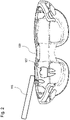
- FIG. 2 10 shows the data glasses 109 for viewing the tooth and for displaying the deviation areas 107.
- the deviation areas 107 to be removed are superimposed directly over the visually perceptible tooth.
- the wearer of the data glasses 109 can see in real time during the tooth preparation at which points the actual tooth shape 103-I deviates from the target tooth shape 103-S.
- the target tooth shape 103-S can be selected manually based on a library that includes a set of target tooth shapes 103-S. Possible target tooth shapes 103 -S can be displayed to the wearer on the data glasses 109 by means of the display device 111 .
- comparison device 105 select target tooth shape 103-S on the basis of previously recorded actual tooth shape 103-I. In this case, from a set of predefined target tooth shapes 103-S, that one can be selected with which most of the tooth substance is preserved in comparison to the actual tooth shape 103-I.
- the comparison device 105 can be designed so that it automatically determines a restoration parameter on the basis of the detected actual tooth shape 103-I.
- a restoration parameter on the basis of the detected actual tooth shape 103-I.
- This can be, for example, a preparation angle that indicates the angle by which the current tooth shape 103-I deviates from a longitudinal crown axis, i.e., for example, half a cone angle.
- it is determined on the basis of the continuously recorded actual tooth shape 103-I which preparation angle it has.
- the wearer of the data glasses 109 is shown the current preparation angle so that he can work on the tooth until the correct preparation angle, ie the angle of the prepared stump, is reached.
- the restoration parameter can also describe other properties, such as other geometric parameters that relate to a tooth stump, an implant, an abutment, undercuts, jawbone situations or an insertion angle, or parameters that relate to the aesthetic situation, such as a color, a point on the tooth, the gingiva, papilla, palatal crease or gums.
- the electronic detection system 101 can detect the position of a treatment tool 115 or a mirror 117 .
- the management system 100 can be designed to continuously record the shape of the tooth by means of the detection system 101 and to generate an electronic file that completely documents the course of a treatment, such as a video file or CAD file.
- the shape of the tooth can also be tracked and assessed afterwards on the basis of the electronic file.
- the detection system 101 can also be designed to optically detect the tooth color of the tooth in addition to the actual tooth shape, for example by acquiring digital color values of the tooth color during a recording. These color values can be saved in the respective data set in addition to the recorded actual tooth shape.
- the guidance system may also include a mirror 117 to assist in capturing the three-dimensional actual tooth shape.
- the detection of the actual tooth shape is accelerated by the mirror 117 in that rear regions of the tooth that are not directly optically accessible, such as an inside of the tooth, can be spatially detected.
- Through the mirror 117 can be easily and quickly determine additional tooth images that can be combined to form a (partial) all-round image of the tooth, which is used for further reconstruction of the actual tooth shape.
- Suitable computer algorithms can generally be used to determine the tooth shape.
- the mirror 117 can, for example, be permanently connected to the optical detection device 111, so that an optical detection can be carried out simultaneously both on the front and on the back of the tooth.
- it can be a mirror with an integrated camera/video system.
- the mirror 117 can also be a hand-held mirror 117 that can be used to obtain dental images of the back of the tooth. These tooth images can also be used for a reconstruction of the actual tooth shape.
- the position of the mirror 117 can be detected by the detection device 101, so that this position can be taken into account when determining the actual tooth shape, for example by means of a ray tracing method.
- All method steps can be implemented by devices that are suitable for carrying out the respective method step. All functions performed by physical features can be a method step of a method.
Landscapes
- Health & Medical Sciences (AREA)
- Life Sciences & Earth Sciences (AREA)
- Surgery (AREA)
- General Health & Medical Sciences (AREA)
- Animal Behavior & Ethology (AREA)
- Public Health (AREA)
- Veterinary Medicine (AREA)
- Oral & Maxillofacial Surgery (AREA)
- Engineering & Computer Science (AREA)
- Heart & Thoracic Surgery (AREA)
- Biomedical Technology (AREA)
- Medical Informatics (AREA)
- Molecular Biology (AREA)
- Nuclear Medicine, Radiotherapy & Molecular Imaging (AREA)
- Physics & Mathematics (AREA)
- Pathology (AREA)
- Dentistry (AREA)
- Epidemiology (AREA)
- Biophysics (AREA)
- Robotics (AREA)
- Radiology & Medical Imaging (AREA)
- Optics & Photonics (AREA)
- General Physics & Mathematics (AREA)
- Audiology, Speech & Language Pathology (AREA)
- Gynecology & Obstetrics (AREA)
- Dental Tools And Instruments Or Auxiliary Dental Instruments (AREA)
Description
Die vorliegende Erfindung betrifft ein dentales Führungssystem zur Zahnpräparation.The present invention relates to a dental guide system for tooth preparation.
Bei der Formgebung von Zähnen im Mund eines Patienten kann es leicht zu Problemen kommen, weil Werkzeuge, wie beispielsweise Bohrer, nicht korrekt verwendet werden. Einmal abgetragenes Zahnmaterial ist dauerhaft entfernt und kann nicht wieder hinzugefügt werden. Grundsätzlich sollte die natürliche Zahnsubstanz soweit wie möglich erhalten bleiben.Problems can easily arise when shaping teeth in a patient's mouth because tools such as drills are not used correctly. Tooth material once removed is permanently removed and cannot be added back. In principle, the natural tooth substance should be preserved as far as possible.
Die Druckschrift
Die Druckschrift
Es ist daher die technische Aufgabe der vorliegenden Erfindung, die manuelle Formgebung von Zähnen im Mund eines Patienten zu vereinfachen und zu beschleunigen.It is therefore the technical task of the present invention to simplify and speed up the manual shaping of teeth in a patient's mouth.
Diese Aufgabe wird durch Gegenstände nach den unabhängigen Ansprüchen gelöst. Vorteilhafte Ausführungsformen sind Gegenstand der abhängigen Ansprüche, der Beschreibung und der Figuren.This object is solved by subject matter according to the independent claims. Advantageous embodiments are the subject matter of the dependent claims, the description and the figures.
Gemäß einem ersten Aspekt wird die vorliegende Aufgabe durch ein dentales Führungssystem zur Zahnpräparation gelöst, mit einem elektronischen Erfassungssystem zum Erfassen einer dreidimensionalen Ist-Zahnform; einer Vergleichseinrichtung zum Ermitteln von räumlichen Abweichungsbereichen, an denen die ermittelte Ist-Zahnform von einer vorgegebenen Soll-Zahnform abweicht; und einer Datenbrille mit einer Anzeigeeinrichtung zum optischen Anzeigen der räumlichen Abweichungsbereiche. Das Erfassen einer dreidimensionalen Ist-Zahnform kann kontinuierlich und in Echtzeit während der Formgebung erfolgen. Durch das elektronische Erfassungssystem wird ein digitaler Datensatz erhalten, der die dreidimensionale Ist-Zahnform beschreibt und der von der Vergleichseinrichtung verarbeitet werden kann. Das Erfassen kann mittels eines optischen Verfahrens oder eines Röntgenverfahrens durchgeführt werden. Im Allgemeinen kann das elektronische Erfassungssystem jedes Erfassungssystem sein, mit dem sich ein digitaler Datensatz für die dreidimensionalen Ist-Zahnform erhalten lässt. Die Abweichungsbereiche werden direkt über den visuell wahrnehmbaren Zahn überlagert. Datenbrille mit der Anzeigeeinrichtung dient zum optischen Anzeigen der räumlichen Abweichungsbereiche über dem visuell wahrnehmbaren Zahn.According to a first aspect, the present object is achieved by a dental guidance system for tooth preparation, with an electronic detection system for detecting a three-dimensional actual tooth shape; a comparison device for determining spatial deviation areas in which the determined actual tooth shape deviates from a predetermined target tooth shape; and data glasses with a display device for optically displaying the spatial deviation areas. The detection of a three-dimensional actual tooth shape can be done continuously and in real time during the shaping done. A digital data set is obtained by the electronic detection system, which describes the three-dimensional actual tooth shape and which can be processed by the comparison device. The detection can be carried out by means of an optical method or an X-ray method. In general, the electronic acquisition system can be any acquisition system with which a digital data set for the three-dimensional actual tooth shape can be obtained. The areas of deviation are superimposed directly over the visually perceptible tooth. Data glasses with the display device are used for the optical display of the spatial deviation areas over the visually perceptible tooth.
Durch das optische Hervorheben von Abweichungsbereichen durch die Datenbrille kann ein behandelnder Zahnarzt unmittelbar erkennen, welche räumlichen Bereiche des Zahns zu entfernen sind, damit die gewünschte Soll-Zahnform erhalten wird. Dadurch wird der technische Vorteil erreicht, dass ein unbeabsichtigtes Abtragen räumlicher Bereiche verhindert werden kann und möglichst viel natürliche Zahnsubstanz erhalten bleibt.By optically highlighting areas of deviation using the data glasses, a treating dentist can immediately see which spatial areas of the tooth need to be removed in order to obtain the desired target tooth shape. This achieves the technical advantage that unintentional removal of spatial areas can be prevented and as much natural tooth substance as possible is preserved.
Die Ist-Zahnform ist beispielsweise die tatsächliche räumliche Form eines Zahnes, eines Kiefers, eines Bohrschablonenersatzes, einer Brücke oder einer Krone. Die Soll-Zahnform ist die räumliche Form des Zahnes, des Kiefers, des Bohrschablonenersatzes, der Brücke oder der Krone, die diese nach der manuellen Bearbeitung aufweisen sollen. Die Datenbrille ist ein als Brille getragenes elektronisches Gerät, mit dem einem Benutzer zusätzlich zur natürlichen visuellen Wahrnehmung weitere Informationen optisch angezeigt werden können. Die Datenbrille kann durch die Anzeigeeinrichtung zusätzliche Informationen auf einem Bild überlagern, das von dem Auge des Trägers wahrgenommen wird.The actual tooth shape is, for example, the actual three-dimensional shape of a tooth, a jaw, a replacement drilling template, a bridge or a crown. The target tooth shape is the three-dimensional shape of the tooth, the jaw, the replacement drilling template, the bridge or the crown that they should have after manual processing. Data glasses are electronic devices worn as glasses, with which further information can be optically displayed to a user in addition to natural visual perception. The data glasses can use the display device to superimpose additional information on an image that is perceived by the wearer's eye.
Die Anzeigeeinrichtung umfasst beispielsweise einen augennahen Bildschirm oder einen Projektor zur direkten Projektion auf der Netzhaut. Daneben können die Informationen auf einem externen Bildschirm angezeigt werden.The display device includes, for example, a screen close to the eye or a projector for direct projection onto the retina. In addition, the information can be displayed on an external screen.
In einer technischen Ausführungsform des dentalen Führungssystems umfasst die Datenbrille das elektronische Erfassungssystem. Durch eine Integration des Erfassungssystems in die Datenbrille wird beispielsweise der technische Vorteil erreicht, dass sich der Aufbau des dentalen Führungssystems vereinfacht.In a technical embodiment of the dental guidance system, the data glasses include the electronic detection system. By integrating the detection system into the data glasses, the technical advantage is achieved, for example, that the structure of the dental guidance system is simplified.
In einer weiteren technisch vorteilhaften Ausführungsform des dentalen Führungssystems umfasst das elektronische Erfassungssystem ein stereoskopisches Erfassungssystem mit einer ersten und einer zweiten Kamera oder ein stereoskopisches Erfassungssystem mit einer plenoptischen Kamera. Eine plenoptische Kamera, auch Lichtfeldkamera genannt, erfasst neben den üblichen zwei Bilddimensionen die Richtung einfallender Lichtstrahlen. Durch die zusätzliche Dimension enthalten plenoptische Aufnahmen Informationen über die Bildtiefe. Dadurch wird beispielsweise der technische Vorteil erreicht, dass die Ist-Zahnform mit geringem technischem Aufwand erfasst werden kann und sich das Erfassungssystem auf einfache Weise in eine Datenbrille integrieren lässt. Außerdem kann das Erfassen der dreidimensionalen Ist-Zahnform auch auf Basis mehrerer Bilder, mittels eines Streifenprojektionsverfahrens oder mittels einer Linsenrasterkamera erfolgen.In a further technically advantageous embodiment of the dental guidance system, the electronic detection system comprises a stereoscopic detection system with a first and a second camera or a stereoscopic detection system with a plenoptic camera. A plenoptic camera, also known as a light field camera, records the direction of incident light rays in addition to the usual two image dimensions. Due to the additional dimension, plenoptic images contain information about the image depth. This achieves the technical advantage, for example, that the actual tooth shape can be recorded with little technical effort and the recording system can be easily integrated into data glasses. In addition, the three-dimensional actual tooth shape can also be recorded on the basis of a number of images, by means of a fringe projection method or by means of a lens raster camera.
In einer weiteren technisch vorteilhaften Ausführungsform des dentalen Führungssystems umfasst das elektronische Erfassungssystem eine 3D-Kamera zum Erfassen einer dreidimensionalen Ist-Zahnform auf Basis einer Laufzeitmessung von Licht. Dadurch wird beispielsweise der technische Vorteil erreicht, dass sich die Zahnform auf schnelle Weise und mit einer kompakten Kamera ermitteln lässt.In a further technically advantageous embodiment of the dental guidance system, the electronic detection system includes a 3D camera for detecting a three-dimensional actual tooth shape on the basis of a transit time measurement of light. This will, for example, the technical advantage achieved that the tooth form can be determined quickly and with a compact camera.
In einer weiteren technischen Ausführungsform des dentalen Führungssystems ist die Vergleichseinrichtung ausgebildet, einen Restaurationsparameter auf Basis der erfassten Ist-Zahnform zu ermitteln. Der Restaurationsparameter ist beispielsweise ein Präparationswinkel, der angibt, um welchen Winkel die Präparation von der Längsachse abweicht. Im Allgemeinen kann es sich bei dem Restaurationsparameter jedoch um jeden Parameter handeln, der bei der Bearbeitung eine Rolle spielt. Dadurch wird beispielsweise der technische Vorteil erreicht, dass Restaurationsparameter überwacht werden können und sich die Formgebung des Zahnes weiter vereinfacht.In a further technical embodiment of the dental guidance system, the comparison device is designed to determine a restoration parameter on the basis of the recorded actual tooth shape. The restoration parameter is, for example, a preparation angle that indicates the angle by which the preparation deviates from the longitudinal axis. In general, however, the restoration parameter can be any parameter that plays a role in processing. This achieves the technical advantage, for example, that restoration parameters can be monitored and the shaping of the tooth is further simplified.
In einer weiteren technischen Ausführungsform des dentalen Führungssystems ist das Führungssystem ausgebildet, den Restaurationsparameter auf der Anzeigeeinrichtung der Datenbrille anzuzeigen. Dadurch wird beispielsweise der technische Vorteil erreicht, dass der Restaurationsparameter bei der manuellen Bearbeitung des Zahnes direkt berücksichtigt werden kann.In a further technical embodiment of the dental guidance system, the guidance system is designed to display the restoration parameter on the display device of the data glasses. This achieves the technical advantage, for example, that the restoration parameters can be directly taken into account during manual processing of the tooth.
In einer weiteren technischen Ausführungsform des dentalen Führungssystems ist das elektronische Erfassungssystem ausgebildet, die dreidimensionale Ist-Zahnform auf Basis einer zeitlichen Serie von Zahnbildern zu ermitteln. Dadurch wird beispielsweise der technische Vorteil erreicht, dass sich die Zahnform auf einfache und genaue Weise ermitteln lässt. Jedes weitere Zahnbild der Serie erhöht die Genauigkeit der ermittelten Ist-Zahnform. Die Serie der Zahnbilder lässt sich beispielsweise zu einem (Teil-) Rundumbild des Zahnes zusammensetzen, das zur weiteren Rekonstruktion der Ist-Zahnform verwendet wird. Hierzu können spezielle Computeralgorithmen verwendet werden.In a further technical embodiment of the dental guidance system, the electronic detection system is designed to determine the three-dimensional actual tooth shape on the basis of a series of tooth images over time. This achieves the technical advantage, for example, that the tooth shape can be determined in a simple and precise manner. Each additional tooth image in the series increases the accuracy of the determined actual tooth shape. The series of tooth images can, for example, be combined to form a (partial) all-round image of the tooth, which is used for further reconstruction of the actual tooth shape. Special computer algorithms can be used for this.
In einer weiteren technischen Ausführungsform des dentalen Führungssystems ist das elektronische Erfassungssystem ausgebildet, die Position eines Behandlungswerkzeuges zu erfassen. Dadurch wird beispielsweise der technische Vorteil erreicht, dass sich die Position des Behandlungswerkzeuges in Echtzeit verfolgen lässt. Auf Basis dieser Position kann das Behandlungswerkzeug gesteuert werden. Aus der ermittelten Position des Behandlungswerkzeuges lässt sich auch auf die Ist-Form zurückschließen, da sich an der Position des Behandlungswerkzeuges kein Zahn befindet. Beispielsweis kann mit einem Tastwerkzeug als Behandlungswerkzeug, dessen Position verfolgt wird, die dreidimensionale Ist-Zahnform berechnet werden.In a further technical embodiment of the dental guidance system, the electronic detection system is designed to detect the position of a treatment tool. This achieves the technical advantage, for example, that the position of the treatment tool can be tracked in real time. The treatment tool can be controlled on the basis of this position. The actual shape can also be deduced from the determined position of the treatment tool, since there is no tooth at the position of the treatment tool. For example, the three-dimensional actual tooth shape can be calculated using a touch tool as a treatment tool whose position is tracked.
In einer weiteren technisch vorteilhaften Ausführungsform des dentalen Führungssystems ist das Führungssystem ausgebildet, eine elektronische Datei zu erzeugen, die einen Ablauf einer Behandlung dokumentiert. Dadurch wird beispielsweise der technische Vorteil erreicht, dass Informationen über die Behandlung dauerhaft elektronisch gespeichert werden können.In a further technically advantageous embodiment of the dental management system, the management system is designed to generate an electronic file that documents the course of a treatment. This achieves the technical advantage, for example, that information about the treatment can be permanently stored electronically.
In einer weiteren technisch vorteilhaften Ausführungsform des dentalen Führungssystems ist das Führungssystem ausgebildet, die räumliche Position der Datenbrille zu erfassen. Dadurch wird beispielsweise der technische Vorteil erreicht, dass die räumliche Position der Datenbrille bei der Ermittlung der dreidimensionalen Ist-Zahnform berücksichtigt werden kann. Dadurch wird die Genauigkeit der ermittelten Ist-Zahnform erhöht. Durch die Berücksichtigung eines Winkels kann die Genauigkeit einer Projektion der Abweichungsinformation in der Datenbrille erhöht werden.In a further technically advantageous embodiment of the dental guidance system, the guidance system is designed to detect the spatial position of the data glasses. This achieves the technical advantage, for example, that the spatial position of the data glasses can be taken into account when determining the three-dimensional actual tooth shape. This increases the accuracy of the determined actual tooth form. By taking an angle into account, the accuracy of a projection of the deviation information in the data glasses can be increased.
In einer weiteren technisch vorteilhaften Ausführungsform des dentalen Führungssystems ist das Erfassungssystem ein optisches Erfassungssystem, das eine Autofocus- oder Zoomfunktion zum Erfassen der Ist-Zahnform umfasst. Die Autofocus-Funktion erlaubt eine automatische Scharfstellung, indem eine Kameraeinstellung an die Entfernung zwischen Kamera und Zahn angepasst wird und der Zahn scharf abgebildet wird. Die Zoom-Funktion erlaubt eine stufenlose Anpassung des Bildausschnitts an den Zahn. Dadurch wird beispielsweise der technische Vorteil erreicht, dass sich die Bedienung und Handhabung des Führungssystems vereinfacht.In a further technically advantageous embodiment of the dental guidance system, the detection system is a optical detection system that includes an autofocus or zoom function for detecting the actual tooth shape. The autofocus function allows automatic focusing by adjusting a camera setting to the distance between the camera and the tooth and the tooth is imaged sharply. The zoom function allows stepless adjustment of the image detail to the tooth. This achieves the technical advantage, for example, that the operation and handling of the guide system is simplified.
In einer weiteren technisch vorteilhaften Ausführungsform des dentalen Führungssystems umfasst das Führungssystem einen Spiegel zum Erfassen der dreidimensionalen Ist-Zahnform. Durch den Spiegel wird beispielsweise der technische Vorteil erreicht, dass rückwärtige Bereiche des Zahnes räumlich erfasst werden können, die nicht direkt optisch zugänglich sind. Dadurch kann eine Rekonstruktion der Ist-Zahnform verbessert werden.In a further technically advantageous embodiment of the dental guidance system, the guidance system includes a mirror for detecting the three-dimensional actual tooth shape. The mirror achieves the technical advantage, for example, that rear areas of the tooth that are not directly optically accessible can be spatially recorded. A reconstruction of the actual tooth shape can be improved as a result.
Ausführungsbeispiele der Erfindung sind in den Zeichnungen dargestellt und werden im Folgenden näher beschrieben.Exemplary embodiments of the invention are shown in the drawings and are described in more detail below.
Es zeigen:
- Fig. 1
- eine schematische Ansicht eines dentalen Führungssystems; und
- Fig. 2
- eine Datenbrille zur Betrachtung eines Zahnes.
- 1
- a schematic view of a dental guidance system; and
- 2
- data glasses for viewing a tooth.
Das dentale Führungssystem 100 umfasst hierzu ein elektronisches Erfassungssystem 101, mit dem sich die dreidimensionale Ist-Zahnform 103-I im Mund des Patienten kontinuierlich während der Formgebung ermitteln lässt. Das Ermitteln der Ist-Zahnform 103-I kann auf optischem Wege erfolgen. Im Allgemeinen kann hierzu jedoch auch jedes andere Verfahren verwendet werden, mit dem sich die räumliche Ist-Zahnform 103-I ermitteln lässt. Das elektronische Erfassungssystem 101 erzeugt beispielsweise einen Datensatz, der die räumliche Form des Zahnes beschreibt.For this purpose, the
Das Erfassungssystem 101 umfasst beispielsweise ein stereoskopisches Kamerasystem mit zwei elektronischen Kameras 113-1, 113-2. Durch die stereoskopische Aufnahme mit den beiden Kameras 113-1, 113-2 lässt sich die räumliche Ist-Zahnform 103-I auf einfache Weise ermitteln und rekonstruieren. Aus den jeweiligen Bildern der Kameras 113-1, 113-2 unter unterschiedlichen Parallaxenwinkeln, lässt sich auf die Ist-Zahnform 103-I mittels eines Computeralgorithmus berechnen.The
Das Erfassungssystem 101 kann auch eine Kamera umfassen, die mit einem Laufzeitverfahren von Licht einzelne Distanzen ermittelt (TOF-Kamera - Time of Flight Kamera). Zu diesem Zweck wird der Zahn mittels eines Lichtpulses ausgeleuchtet und für jeden Bildpunkt die Zeit gemessen, die das Licht bis zum Objekt und wieder zurück braucht. Diese Zeit ist direkt proportional zur Distanz. Die Kamera liefert für jeden Bildpunkt die Entfernung des darauf abgebildeten Zahnes.The
Das Erfassungssystem 101 kann die Ist-Zahnform 103-I auch auf einer Serie von Zahnbildern des Zahnes ermitteln, die aus unterschiedlichen Blickwinkeln gewonnen worden sind. Zu diesem Zweck kann ein Berechnungsverfahren verwendet werden, dass aus den einzelnen Zahnbildern die Ist-Zahnform 103-I rekonstruiert. Hierzu kann zusätzlich eine Information über die räumliche Position des Erfassungssystems 101 verwendet werden.The
Das Erfassungssystem 101 kann jedoch auch auf einem Computertomographieverfahren, Röntgenverfahren oder einem Magnetresonanzverfahren basieren, um die Ist-Zahnform 103-I zu ermitteln. Dadurch wird der Vorteil erreicht, dass sich auch dreidimensionale Formen bestimmen lassen, die optisch nicht zugänglich sind, wie beispielsweise Zahnformen mit Läsionen. Durch diese Verfahren kann somit die Innensituation und das Innenvolumen des Zahnes erfasst werden. Umfasst beispielsweise der Zahn ein Loch, so kann eine entsprechende Ist-Zahnform erhalten werden, die nicht nur die äußere optisch wahrnehmbare Oberfläche wiedergibt. Die räumliche Form des Loches kann über die Anzeigeeinrichtung 111 angezeigt werden, so dass auch in diesem Fall das Erzeugen der Soll-Zahnform unterstützt werden kann. Bei minimalinvasiven Verfahren kann dadurch die Position des Bohrloches bestimmt werden.However, the
Die ermittelte Ist-Zahnform 103-I wird einer elektronischen Vergleichseinrichtung 105 als Datensatz zugeführt. Die Vergleichseinrichtung 105 ermittelt die räumlichen Abweichungsbereiche 107, an denen die ermittelte Ist-Zahnform 103-I von einer vorgegebenen Soll-Zahnform 103-S abweicht.The determined actual tooth shape 103-I is fed to an
Die Soll-Zahnform 103-S wird beispielsweise zuvor in einem Zwischenschritt über eine Benutzerschnittstelle ausgewählt oder automatisch an Hand von klinischen Fällen, beispielsweise aus einer Datenbank oder durch Algorithmen (Maschine Learning), vorgeschlagen oder speziell gestaltet, beispielsweise mit einem CAD-Verfahren, und der elektronischen Vergleichseinrichtung 105 ebenfalls als Datensatz zugeführt. Eine Datenbank kann eine Anzahl an Datensätzen für mögliche Soll-Zahnformen speichern. Diese Menge an Soll-Zahnformen kann entweder automatisch oder manuell ausgewählt werden. Zudem ist es möglich vorgegebene Soll-Zahnformen über eine Benutzerschnittstelle zu verändern.The target tooth shape 103-S is, for example, previously selected in an intermediate step via a user interface or automatically based on clinical cases, for example from a database or by algorithms (machine Learning) proposed or specially designed, for example with a CAD method, and the
Zum Ermitteln der Abweichung wird beispielsweise der Datensatz, der die räumliche Ist-Zahnform 103-I beschreibt, mit dem anderen Datensatz verglichen, der die Soll-Zahnform 103-S beschreibt. Stimmen beispielsweise Ist- und Soll-Zahnform 103-I, 103-S im Rahmen eines vorgegebenen Toleranzwertes nicht überein, wird der entsprechende Bereich als ein Abweichungsbereich 107 erfasst.To determine the deviation, for example, the data set that describes the spatial actual tooth shape 103-I is compared with the other data set that describes the target tooth shape 103-S. If, for example, the actual and target tooth shape 103 -I, 103 -S do not match within the framework of a specified tolerance value, the corresponding area is recorded as a
Die elektronische Vergleichseinrichtung 105 ist beispielsweise durch ein Software-Modul gebildet, das auf einer Computereinrichtung mit einem Prozessor und einem elektronischen Speicher zum Speichern des Softwaremoduls und der Datensätze ausgeführt wird.The
Die so ermittelten räumlichen Abweichungsbereiche 107 werden an die Datenbrille 109 übermittelt, durch die die Zahnpräparation unterstützt wird. Die Datenbrille 109 hebt die Abweichungsbereiche 107 optisch hervor.The
Die Datenbrille 109 (auch Augmented-Reality-Brille oder Smart-Glasses) ist ein tragbares Gerät, das in der Lage ist, virtuell Informationen vor die Augen des Brillenträgers zu projizieren, während dieser die Umwelt weiterhin visuell wahrnehmen kann. Dadurch können Informationen in dem Sichtfeld des Trägers angezeigt und hinzugefügt werden. Zu diesem Zweck umfasst die Datenbrille 109 eine Anzeigeeinrichtung 111, die aus einem augennahen Bildschirm oder einen Projektor zur direkten Projektion auf der Netzhaut gebildet sein kann.The data glasses 109 (also augmented reality glasses or smart glasses) are wearable devices that are able to project virtual information in front of the eyes of the glasses wearer, while the latter can continue to perceive the environment visually. This allows information to be displayed and added to the wearer's field of vision. For this purpose, the
Die Anzeigeeinrichtung 111 dient zum Anzeigen derjenigen Bereiche, an denen die ermittelte Ist-Zahnform 103-I von der vorgegebenen Soll-Zahnform 103-S abweicht. Auf diese Weise kann ein Träger der Datenbrille 109 unmittelbar auf dem visuell wahrgenommenen Zahn erkennen, welche räumlichen Bereiche von dem Zahn entfernt werden müssen, um die gewünschte Soll-Zahnform 103-S zu erhalten. Der Träger der Datenbrille 109 verwendet ein dentales Werkzeug, wie beispielsweise einen Bohrer oder Fräser, um die hervorgehobenen räumlichen Bereiche des Zahnes zu entfernen.The
Die Datenbrille 109 kann zusätzlich noch Sensoren zur Bewegungserfassung des Kopfes oder zur räumlichen Positionserkennung der Datenbrille 109 umfassen, wie beispielsweise einen Gyrosensor. Damit kann die Anzeige der berechneten Abweichungsbereiche 107 genauer an die Bewegungen des Trägers angepasst werden. Die räumliche Position der Datenbrille 109 kann beispielsweise auf Basis vorgegebener optischer Referenzpunkte oder Marker erfolgen, die in der Umgebung der Datenbrille 109 angeordnet sind, wie beispielsweise mittels einer Trilateration oder einer Triangulation.The
Das Erfassungssystem 101 kann in die Datenbrille 109 integriert sein. Dadurch ergibt sich der technische Vorteil, dass die Ist-Zahnform 103-I auf einfache Weise während dem Tragen der Datenbrille 109 durchgeführt werden kann. Im Allgemeinen kann das Erfassungssystem 101 auch als separates Gerät vorgesehen sein, mit dem die Ist-Zahnform 103-I während der Formgebung ermittelt wird.The
Die Soll-Zahnform 103-S kann manuell auf Basis einer Bibliothek ausgewählt werden, die eine Menge an Soll-Zahnformen 103-S umfasst. Mögliche Soll-Zahnformen 103-S können dem Träger auf der Datenbrille 109 mittels der Anzeigeeinrichtung 111 angezeigt werden.The target tooth shape 103-S can be selected manually based on a library that includes a set of target tooth shapes 103-S. Possible target tooth shapes 103 -S can be displayed to the wearer on the
Allerdings ist es auch möglich, dass die Vergleichseinrichtung 105 die Soll-Zahnform 103-S auf Basis der zuvor erfassten Ist-Zahnform 103-I auswählt. In diesem Fall kann aus einer Menge an vorgegebenen Soll-Zahnformen 103-S diejenige ausgewählt werden, mit der im Vergleich zur Ist-Zahnform 103-I die meiste Zahnsubstanz erhalten bleibt.However, it is also possible for
Zudem kann die Vergleichseinrichtung 105 ausgebildet sein, dass diese einen Restaurationsparameter auf Basis der erfassten Ist-Zahnform 103-I automatisch ermittelt. Dieser kann beispielsweise ein Präparationswinkel sein, der angibt, um welchen Winkel die gegenwärtige Ist-Zahnform 103-I von einer Kronenlängsachse abweicht, d.h. beispielsweise ein halber Kegelwinkel. Zu diesem Zweck wird auf Basis der kontinuierlich erfassten Ist-Zahnform 103-I ermittelt, welchen Präparationswinkel diese aufweist.In addition, the
Der Träger der Datenbrille 109 erhält den aktuellen Präparationswinkel angezeigt, so dass dieser den Zahn solange bearbeiten kann bis der richtige Präparationswinkel, d.h. der Winkel des präparierten Stumpfes, erreicht ist.The wearer of the
Im Allgemeinen kann der Restaurationsparameter jedoch auch andere Eigenschaften beschreiben, wie beispielsweise andere geometrische Parameter, die einen Zahnstumpf, ein Implantat, ein Abutment, Hinterschnitte, Kieferknochensituationen oder einen Einschubwinkel betreffen oder Parameter, die die ästhetische Situation betreffen, wie beispielsweise eine Farbe, einen Punkt auf dem Zahn, die Gingiva, Papille, Gaumenfalte oder das Zahnfleisch. Zusätzlich kann das elektronische Erfassungssystem 101 die Position eines Behandlungswerkzeuges 115 oder eines Spiegels 117 erfassen.In general, however, the restoration parameter can also describe other properties, such as other geometric parameters that relate to a tooth stump, an implant, an abutment, undercuts, jawbone situations or an insertion angle, or parameters that relate to the aesthetic situation, such as a color, a point on the tooth, the gingiva, papilla, palatal crease or gums. In addition, the
Weiter kann das Führungssystem 100 ausgebildet sein, die Formgebung des Zahnes mittels des Erfassungssystems 101 kontinuierlich zu erfassen und eine elektronische Datei zu erzeugen, die einen Ablauf einer Behandlung lückenlos dokumentiert, wie beispielsweise eine Videodatei oder CAD-Datei. In diesem Fall kann auch im Nachhinein die Formgebung des Zahnes auf Basis der elektronischen Datei verfolgt und begutachtet werden.Furthermore, the
Das Erfassungssystem 101 kann zudem ausgebildet sein, zusätzlich zur Ist-Zahnform die Zahnfarbe des Zahnes optisch zu erfassen, beispielsweise indem digitale Farbwerte der Zahnfarbe während einer Aufnahme gewonnen werden. Diese Farbwerte können zusätzlich zur erfassten Ist-Zahnform in dem jeweiligen Datensatz gespeichert werden.The
Das Führungssystem kann zudem einen Spiegel 117 zum Unterstützen des Erfassens der dreidimensionalen Ist-Zahnform aufweisen. Durch den Spiegel 117 wird die Erfassung der Ist-Zahnform beschleunigt, indem rückwärtige Bereiche des Zahnes räumlich erfasst werden können, die nicht direkt optisch zugänglich sind, wie beispielsweise eine Innenseite des Zahnes. Durch den Spiegel 117 lassen sich auf einfache und schnelle Weise zusätzliche Zahnbilder ermitteln, die zu einem (Teil-) Rundumbild des Zahnes zusammengesetzt werden können, das zur weiteren Rekonstruktion der Ist-Zahnform verwendet wird. Zum Ermitteln der Zahnform können im Allgemeinen geeignete Computeralgorithmen verwendet werden.The guidance system may also include a
Der Spiegel 117 kann beispielsweise fest mit der optischen Erfassungseinrichtung 111 verbunden sein, so dass eine optische Erfassung gleichzeitig sowohl auf der Vorderseite als auch der Rückseite des Zahnes durchgeführt werden kann. Beispielsweise kann es sich um einen Spiegel mit integriertem Kamera-/Videosystem handeln.The
Im Allgemeinen kann der Spiegel 117 jedoch auch ein in der Hand gehaltener Spiegel 117 sein, mit dem sich Zahnbilder der Rückseite des Zahnes erhalten lassen. Diese Zahnbilder können ebenfalls für eine Rekonstruktion der Ist-Zahnform herangezogen werden. Zudem kann durch die Erfassungseinrichtung 101 die Position des Spiegels 117 erfasst werden, so dass diese Position bei der Ermittlung der Ist-Zahnform berücksichtigt werden kann, wie beispielsweise mittels eines Ray-Tracing-Verfahrens.However, in general, the
Alle in Verbindung mit einzelnen Ausführungsformen der Erfindung erläuterten und gezeigten Merkmale können in unterschiedlicher Kombination in dem erfindungsgemäßen Gegenstand vorgesehen sein, um gleichzeitig deren vorteilhafte Wirkungen zu realisieren.All of the features explained and shown in connection with individual embodiments of the invention can be provided in different combinations in the object according to the invention in order to realize their advantageous effects at the same time.
Alle Verfahrensschritte können durch Vorrichtungen implementiert werden, die zum Ausführen des jeweiligen Verfahrensschrittes geeignet sind. Alle Funktionen, die von gegenständlichen Merkmalen ausgeführt werden, können ein Verfahrensschritt eines Verfahrens sein.All method steps can be implemented by devices that are suitable for carrying out the respective method step. All functions performed by physical features can be a method step of a method.
Der Schutzbereich der vorliegenden Erfindung ist durch die Ansprüche gegeben und wird durch die in der Beschreibung erläuterten oder den Figuren gezeigten Merkmale nicht beschränkt.The scope of protection of the present invention is given by the claims and is not limited by the features explained in the description or shown in the figures.
- 100100
- Dentales FührungssystemDental guidance system
- 101101
- Erfassungssystemdetection system
- 103-I103-I
- Ist-Zahnformactual tooth form
- 103-S103-p
- Soll-ZahnformTarget tooth form
- 105105
- Vergleichseinrichtungcomparison device
- 107107
- Abweichungsbereichdeviation range
- 109109
- Datenbrilledata glasses
- 111111
- Anzeigeeinrichtungdisplay device
- 113-1113-1
- Kameracamera
- 113-2113-2
- Kameracamera
- 115115
- Behandlungswerkzeugtreatment tool
- 117117
- Spiegelmirror
Claims (7)
- Dental guidance system (100) for tooth preparation, which is adapted to display the restoration parameter on the display device (111) of the data glasses (109), comprising:- an electronic detection system (101) for detecting a three-dimensional actual tooth shape (103-1), which is adapted to determine the three-dimensional actual tooth shape (103-1) on the basis of a time series of tooth images and to detect the position of a treatment tool (115) ;- a comparison means (105) for determining spatial deviation regions (107) at which the determined actual tooth form (103-1) deviates from a predetermined desired tooth form (103-S) and which is designed to determine a restoration parameter on the basis of the detected actual tooth form (103-1); and- data glasses (109) having display means (111) for optically displaying the spatial deviation regions (107), comprising the electronic detection system (101).
- Dental guidance system (100) according to claim 1, wherein said electronic detection system (101) comprises a stereoscopic detection system with a first and a second camera (113-1, 113-2) or a stereoscopic detection system with a plenoptic camera.
- Dental guidance system (100) according to any one of the preceding claims, wherein the electronic acquisition system (101) comprises a 3D camera for acquiring a three-dimensional actual tooth shape (103-1) based on a time-of-flight measurement of light.
- Dental guidance system (100) according to any one of the preceding claims, wherein the guidance system (100) is adapted to generate an electronic file documenting a course of treatment.
- Dental guidance system (100) according to any one of the preceding claims, wherein the guidance system (100) is configured to detect the spatial position of the data glasses (109).
- Dental guidance system (100) according to any one of the preceding claims, wherein the detection system (101) is an optical detection system comprising an autofocus or zoom function for detecting the actual tooth shape.
- Dental guidance system (100) according to any one of the preceding claims, wherein the guidance system (100) comprises a mirror (117) for detecting the three-dimensional actual tooth shape (103-1).
Priority Applications (4)
| Application Number | Priority Date | Filing Date | Title |
|---|---|---|---|
| EP18199458.3A EP3636202B1 (en) | 2018-10-09 | 2018-10-09 | Dental guiding system for dental preparation |
| PCT/EP2019/074332 WO2020074204A1 (en) | 2018-10-09 | 2019-09-12 | Dental guide system for tooth preparation |
| US17/281,607 US20210386512A1 (en) | 2018-10-09 | 2019-09-12 | Method Tool And Method Of Operating A Machine Tool |
| CN201980066621.0A CN112839609A (en) | 2018-10-09 | 2019-09-12 | Dental guidance system for dental preparation |
Applications Claiming Priority (1)
| Application Number | Priority Date | Filing Date | Title |
|---|---|---|---|
| EP18199458.3A EP3636202B1 (en) | 2018-10-09 | 2018-10-09 | Dental guiding system for dental preparation |
Publications (2)
| Publication Number | Publication Date |
|---|---|
| EP3636202A1 EP3636202A1 (en) | 2020-04-15 |
| EP3636202B1 true EP3636202B1 (en) | 2022-06-15 |
Family
ID=63832254
Family Applications (1)
| Application Number | Title | Priority Date | Filing Date |
|---|---|---|---|
| EP18199458.3A Active EP3636202B1 (en) | 2018-10-09 | 2018-10-09 | Dental guiding system for dental preparation |
Country Status (4)
| Country | Link |
|---|---|
| US (1) | US20210386512A1 (en) |
| EP (1) | EP3636202B1 (en) |
| CN (1) | CN112839609A (en) |
| WO (1) | WO2020074204A1 (en) |
Family Cites Families (5)
| Publication number | Priority date | Publication date | Assignee | Title |
|---|---|---|---|---|
| ES2724115T3 (en) * | 2007-06-29 | 2019-09-06 | Midmark Corp | Graphical user interface for computer-assisted margin marking on dentures |
| JP5043145B2 (en) * | 2010-04-01 | 2012-10-10 | 俊道 森 | Diagnostic system |
| EP3097448A1 (en) * | 2014-01-21 | 2016-11-30 | Trophy | Method for implant surgery using augmented visualization |
| EP2937058B1 (en) * | 2014-04-24 | 2020-10-07 | Christof Ellerbrock | Head mounted platform for integration of virtuality into reality |
| US10888399B2 (en) * | 2016-12-16 | 2021-01-12 | Align Technology, Inc. | Augmented reality enhancements for dental practitioners |
-
2018
- 2018-10-09 EP EP18199458.3A patent/EP3636202B1/en active Active
-
2019
- 2019-09-12 CN CN201980066621.0A patent/CN112839609A/en active Pending
- 2019-09-12 WO PCT/EP2019/074332 patent/WO2020074204A1/en active Application Filing
- 2019-09-12 US US17/281,607 patent/US20210386512A1/en active Pending
Also Published As
| Publication number | Publication date |
|---|---|
| WO2020074204A1 (en) | 2020-04-16 |
| EP3636202A1 (en) | 2020-04-15 |
| CN112839609A (en) | 2021-05-25 |
| US20210386512A1 (en) | 2021-12-16 |
Similar Documents
| Publication | Publication Date | Title |
|---|---|---|
| EP2337498B1 (en) | Method for producing a dental 3d x-ray image | |
| EP1181814B1 (en) | Method for detecting and representing one or more objects, for example teeth | |
| EP3376989A1 (en) | Method for visualizing a tooth situation | |
| EP2937058B1 (en) | Head mounted platform for integration of virtuality into reality | |
| DE102015212806A1 (en) | System and method for scanning anatomical structures and displaying a scan result | |
| EP0741994A1 (en) | Method for presentation of the jaw | |
| DE112009000100T5 (en) | Navigate between images of an object in 3D space | |
| WO2013181678A1 (en) | Method for continuation of image capture for acquiring three-dimensional geometries of objects | |
| DE102014207667A1 (en) | Method for carrying out an optical three-dimensional recording | |
| EP2914201B1 (en) | Method for determining at least one relevant single image of a dental subject | |
| EP2846729B1 (en) | Method for measuring a dental situation | |
| EP3389496A1 (en) | Method for calibrating an x-ray image | |
| DE102014102111B4 (en) | Method for visualizing dental relevant anatomical relations and / or structures | |
| EP3636202B1 (en) | Dental guiding system for dental preparation | |
| DE102018204098A1 (en) | Image output method during a dental application and image output device | |
| EP3113715B1 (en) | Insertion post, system and method for detecting the position of an inserted implant | |
| EP3312800B1 (en) | Method for cleaning up virtual representation of objects | |
| EP3636159A1 (en) | Dental tool control system | |
| AT516002B1 (en) | Method for creating a digital denture model | |
| DE102015104560A1 (en) | Method for operating a surgical microscope arrangement | |
| AT525473B1 (en) | Arrangement for detecting a position of a human upper jaw and/or head | |
| DE102022102335A1 (en) | Method and system for recording and displaying movements of the teeth and/or joints of the lower jaw |
Legal Events
| Date | Code | Title | Description |
|---|---|---|---|
| PUAI | Public reference made under article 153(3) epc to a published international application that has entered the european phase |
Free format text: ORIGINAL CODE: 0009012 |
|
| STAA | Information on the status of an ep patent application or granted ep patent |
Free format text: STATUS: THE APPLICATION HAS BEEN PUBLISHED |
|
| AK | Designated contracting states |
Kind code of ref document: A1 Designated state(s): AL AT BE BG CH CY CZ DE DK EE ES FI FR GB GR HR HU IE IS IT LI LT LU LV MC MK MT NL NO PL PT RO RS SE SI SK SM TR |
|
| AX | Request for extension of the european patent |
Extension state: BA ME |
|
| STAA | Information on the status of an ep patent application or granted ep patent |
Free format text: STATUS: REQUEST FOR EXAMINATION WAS MADE |
|
| 17P | Request for examination filed |
Effective date: 20200729 |
|
| RBV | Designated contracting states (corrected) |
Designated state(s): AL AT BE BG CH CY CZ DE DK EE ES FI FR GB GR HR HU IE IS IT LI LT LU LV MC MK MT NL NO PL PT RO RS SE SI SK SM TR |
|
| STAA | Information on the status of an ep patent application or granted ep patent |
Free format text: STATUS: EXAMINATION IS IN PROGRESS |
|
| STAA | Information on the status of an ep patent application or granted ep patent |
Free format text: STATUS: EXAMINATION IS IN PROGRESS |
|
| 17Q | First examination report despatched |
Effective date: 20201216 |
|
| GRAP | Despatch of communication of intention to grant a patent |
Free format text: ORIGINAL CODE: EPIDOSNIGR1 |
|
| STAA | Information on the status of an ep patent application or granted ep patent |
Free format text: STATUS: GRANT OF PATENT IS INTENDED |
|
| INTG | Intention to grant announced |
Effective date: 20210723 |
|
| GRAJ | Information related to disapproval of communication of intention to grant by the applicant or resumption of examination proceedings by the epo deleted |
Free format text: ORIGINAL CODE: EPIDOSDIGR1 |
|
| STAA | Information on the status of an ep patent application or granted ep patent |
Free format text: STATUS: EXAMINATION IS IN PROGRESS |
|
| INTC | Intention to grant announced (deleted) | ||
| STAA | Information on the status of an ep patent application or granted ep patent |
Free format text: STATUS: EXAMINATION IS IN PROGRESS |
|
| GRAP | Despatch of communication of intention to grant a patent |
Free format text: ORIGINAL CODE: EPIDOSNIGR1 |
|
| STAA | Information on the status of an ep patent application or granted ep patent |
Free format text: STATUS: GRANT OF PATENT IS INTENDED |
|
| INTG | Intention to grant announced |
Effective date: 20220328 |
|
| GRAS | Grant fee paid |
Free format text: ORIGINAL CODE: EPIDOSNIGR3 |
|
| GRAA | (expected) grant |
Free format text: ORIGINAL CODE: 0009210 |
|
| STAA | Information on the status of an ep patent application or granted ep patent |
Free format text: STATUS: THE PATENT HAS BEEN GRANTED |
|
| AK | Designated contracting states |
Kind code of ref document: B1 Designated state(s): AL AT BE BG CH CY CZ DE DK EE ES FI FR GB GR HR HU IE IS IT LI LT LU LV MC MK MT NL NO PL PT RO RS SE SI SK SM TR |
|
| REG | Reference to a national code |
Ref country code: CH Ref legal event code: EP Ref country code: GB Ref legal event code: FG4D Free format text: NOT ENGLISH |
|
| REG | Reference to a national code |
Ref country code: IE Ref legal event code: FG4D Free format text: LANGUAGE OF EP DOCUMENT: GERMAN |
|
| REG | Reference to a national code |
Ref country code: DE Ref legal event code: R096 Ref document number: 502018009908 Country of ref document: DE |
|
| REG | Reference to a national code |
Ref country code: AT Ref legal event code: REF Ref document number: 1497923 Country of ref document: AT Kind code of ref document: T Effective date: 20220715 |
|
| REG | Reference to a national code |
Ref country code: LT Ref legal event code: MG9D |
|
| REG | Reference to a national code |
Ref country code: NL Ref legal event code: MP Effective date: 20220615 |
|
| PG25 | Lapsed in a contracting state [announced via postgrant information from national office to epo] |
Ref country code: SE Free format text: LAPSE BECAUSE OF FAILURE TO SUBMIT A TRANSLATION OF THE DESCRIPTION OR TO PAY THE FEE WITHIN THE PRESCRIBED TIME-LIMIT Effective date: 20220615 Ref country code: NO Free format text: LAPSE BECAUSE OF FAILURE TO SUBMIT A TRANSLATION OF THE DESCRIPTION OR TO PAY THE FEE WITHIN THE PRESCRIBED TIME-LIMIT Effective date: 20220915 Ref country code: LT Free format text: LAPSE BECAUSE OF FAILURE TO SUBMIT A TRANSLATION OF THE DESCRIPTION OR TO PAY THE FEE WITHIN THE PRESCRIBED TIME-LIMIT Effective date: 20220615 Ref country code: HR Free format text: LAPSE BECAUSE OF FAILURE TO SUBMIT A TRANSLATION OF THE DESCRIPTION OR TO PAY THE FEE WITHIN THE PRESCRIBED TIME-LIMIT Effective date: 20220615 Ref country code: GR Free format text: LAPSE BECAUSE OF FAILURE TO SUBMIT A TRANSLATION OF THE DESCRIPTION OR TO PAY THE FEE WITHIN THE PRESCRIBED TIME-LIMIT Effective date: 20220916 Ref country code: FI Free format text: LAPSE BECAUSE OF FAILURE TO SUBMIT A TRANSLATION OF THE DESCRIPTION OR TO PAY THE FEE WITHIN THE PRESCRIBED TIME-LIMIT Effective date: 20220615 Ref country code: BG Free format text: LAPSE BECAUSE OF FAILURE TO SUBMIT A TRANSLATION OF THE DESCRIPTION OR TO PAY THE FEE WITHIN THE PRESCRIBED TIME-LIMIT Effective date: 20220915 |
|
| PG25 | Lapsed in a contracting state [announced via postgrant information from national office to epo] |
Ref country code: RS Free format text: LAPSE BECAUSE OF FAILURE TO SUBMIT A TRANSLATION OF THE DESCRIPTION OR TO PAY THE FEE WITHIN THE PRESCRIBED TIME-LIMIT Effective date: 20220615 Ref country code: LV Free format text: LAPSE BECAUSE OF FAILURE TO SUBMIT A TRANSLATION OF THE DESCRIPTION OR TO PAY THE FEE WITHIN THE PRESCRIBED TIME-LIMIT Effective date: 20220615 |
|
| PG25 | Lapsed in a contracting state [announced via postgrant information from national office to epo] |
Ref country code: NL Free format text: LAPSE BECAUSE OF FAILURE TO SUBMIT A TRANSLATION OF THE DESCRIPTION OR TO PAY THE FEE WITHIN THE PRESCRIBED TIME-LIMIT Effective date: 20220615 |
|
| PG25 | Lapsed in a contracting state [announced via postgrant information from national office to epo] |
Ref country code: SM Free format text: LAPSE BECAUSE OF FAILURE TO SUBMIT A TRANSLATION OF THE DESCRIPTION OR TO PAY THE FEE WITHIN THE PRESCRIBED TIME-LIMIT Effective date: 20220615 Ref country code: SK Free format text: LAPSE BECAUSE OF FAILURE TO SUBMIT A TRANSLATION OF THE DESCRIPTION OR TO PAY THE FEE WITHIN THE PRESCRIBED TIME-LIMIT Effective date: 20220615 Ref country code: RO Free format text: LAPSE BECAUSE OF FAILURE TO SUBMIT A TRANSLATION OF THE DESCRIPTION OR TO PAY THE FEE WITHIN THE PRESCRIBED TIME-LIMIT Effective date: 20220615 Ref country code: PT Free format text: LAPSE BECAUSE OF FAILURE TO SUBMIT A TRANSLATION OF THE DESCRIPTION OR TO PAY THE FEE WITHIN THE PRESCRIBED TIME-LIMIT Effective date: 20221017 Ref country code: ES Free format text: LAPSE BECAUSE OF FAILURE TO SUBMIT A TRANSLATION OF THE DESCRIPTION OR TO PAY THE FEE WITHIN THE PRESCRIBED TIME-LIMIT Effective date: 20220615 Ref country code: EE Free format text: LAPSE BECAUSE OF FAILURE TO SUBMIT A TRANSLATION OF THE DESCRIPTION OR TO PAY THE FEE WITHIN THE PRESCRIBED TIME-LIMIT Effective date: 20220615 Ref country code: CZ Free format text: LAPSE BECAUSE OF FAILURE TO SUBMIT A TRANSLATION OF THE DESCRIPTION OR TO PAY THE FEE WITHIN THE PRESCRIBED TIME-LIMIT Effective date: 20220615 |
|
| PG25 | Lapsed in a contracting state [announced via postgrant information from national office to epo] |
Ref country code: PL Free format text: LAPSE BECAUSE OF FAILURE TO SUBMIT A TRANSLATION OF THE DESCRIPTION OR TO PAY THE FEE WITHIN THE PRESCRIBED TIME-LIMIT Effective date: 20220615 Ref country code: IS Free format text: LAPSE BECAUSE OF FAILURE TO SUBMIT A TRANSLATION OF THE DESCRIPTION OR TO PAY THE FEE WITHIN THE PRESCRIBED TIME-LIMIT Effective date: 20221015 |
|
| REG | Reference to a national code |
Ref country code: DE Ref legal event code: R097 Ref document number: 502018009908 Country of ref document: DE |
|
| PG25 | Lapsed in a contracting state [announced via postgrant information from national office to epo] |
Ref country code: AL Free format text: LAPSE BECAUSE OF FAILURE TO SUBMIT A TRANSLATION OF THE DESCRIPTION OR TO PAY THE FEE WITHIN THE PRESCRIBED TIME-LIMIT Effective date: 20220615 |
|
| PLBE | No opposition filed within time limit |
Free format text: ORIGINAL CODE: 0009261 |
|
| STAA | Information on the status of an ep patent application or granted ep patent |
Free format text: STATUS: NO OPPOSITION FILED WITHIN TIME LIMIT |
|
| PG25 | Lapsed in a contracting state [announced via postgrant information from national office to epo] |
Ref country code: DK Free format text: LAPSE BECAUSE OF FAILURE TO SUBMIT A TRANSLATION OF THE DESCRIPTION OR TO PAY THE FEE WITHIN THE PRESCRIBED TIME-LIMIT Effective date: 20220615 |
|
| 26N | No opposition filed |
Effective date: 20230316 |
|
| PG25 | Lapsed in a contracting state [announced via postgrant information from national office to epo] |
Ref country code: SI Free format text: LAPSE BECAUSE OF FAILURE TO SUBMIT A TRANSLATION OF THE DESCRIPTION OR TO PAY THE FEE WITHIN THE PRESCRIBED TIME-LIMIT Effective date: 20220615 Ref country code: MC Free format text: LAPSE BECAUSE OF FAILURE TO SUBMIT A TRANSLATION OF THE DESCRIPTION OR TO PAY THE FEE WITHIN THE PRESCRIBED TIME-LIMIT Effective date: 20220615 |
|
| REG | Reference to a national code |
Ref country code: BE Ref legal event code: MM Effective date: 20221031 |
|
| PG25 | Lapsed in a contracting state [announced via postgrant information from national office to epo] |
Ref country code: LU Free format text: LAPSE BECAUSE OF NON-PAYMENT OF DUE FEES Effective date: 20221009 |
|
| P01 | Opt-out of the competence of the unified patent court (upc) registered |
Effective date: 20230607 |
|
| PG25 | Lapsed in a contracting state [announced via postgrant information from national office to epo] |
Ref country code: BE Free format text: LAPSE BECAUSE OF NON-PAYMENT OF DUE FEES Effective date: 20221031 |
|
| PG25 | Lapsed in a contracting state [announced via postgrant information from national office to epo] |
Ref country code: IE Free format text: LAPSE BECAUSE OF NON-PAYMENT OF DUE FEES Effective date: 20221009 |
|
| PGFP | Annual fee paid to national office [announced via postgrant information from national office to epo] |
Ref country code: GB Payment date: 20230907 Year of fee payment: 6 |
|
| PGFP | Annual fee paid to national office [announced via postgrant information from national office to epo] |
Ref country code: FR Payment date: 20230907 Year of fee payment: 6 |
|
| PGFP | Annual fee paid to national office [announced via postgrant information from national office to epo] |
Ref country code: IT Payment date: 20231023 Year of fee payment: 6 Ref country code: DE Payment date: 20230904 Year of fee payment: 6 Ref country code: CH Payment date: 20231102 Year of fee payment: 6 Ref country code: AT Payment date: 20230911 Year of fee payment: 6 |
|
| PG25 | Lapsed in a contracting state [announced via postgrant information from national office to epo] |
Ref country code: HU Free format text: LAPSE BECAUSE OF FAILURE TO SUBMIT A TRANSLATION OF THE DESCRIPTION OR TO PAY THE FEE WITHIN THE PRESCRIBED TIME-LIMIT; INVALID AB INITIO Effective date: 20181009 |
|
| PG25 | Lapsed in a contracting state [announced via postgrant information from national office to epo] |
Ref country code: CY Free format text: LAPSE BECAUSE OF FAILURE TO SUBMIT A TRANSLATION OF THE DESCRIPTION OR TO PAY THE FEE WITHIN THE PRESCRIBED TIME-LIMIT Effective date: 20220615 |