EP3636120B1 - Oil discharge roast pan and cooking device having same - Google Patents
Oil discharge roast pan and cooking device having same Download PDFInfo
- Publication number
- EP3636120B1 EP3636120B1 EP19202176.4A EP19202176A EP3636120B1 EP 3636120 B1 EP3636120 B1 EP 3636120B1 EP 19202176 A EP19202176 A EP 19202176A EP 3636120 B1 EP3636120 B1 EP 3636120B1
- Authority
- EP
- European Patent Office
- Prior art keywords
- oil discharge
- protrusions
- pan
- support portions
- roast
- Prior art date
- Legal status (The legal status is an assumption and is not a legal conclusion. Google has not performed a legal analysis and makes no representation as to the accuracy of the status listed.)
- Active
Links
- 238000010411 cooking Methods 0.000 title claims description 21
- 235000013305 food Nutrition 0.000 claims description 35
- 238000010438 heat treatment Methods 0.000 claims description 16
- 239000004519 grease Substances 0.000 description 13
- 239000000779 smoke Substances 0.000 description 4
- 230000002093 peripheral effect Effects 0.000 description 3
- 230000003247 decreasing effect Effects 0.000 description 2
- 230000000694 effects Effects 0.000 description 2
- 230000015572 biosynthetic process Effects 0.000 description 1
- 238000004140 cleaning Methods 0.000 description 1
- 235000013372 meat Nutrition 0.000 description 1
- 238000000034 method Methods 0.000 description 1
- 238000013021 overheating Methods 0.000 description 1
Images


Classifications
-
- A—HUMAN NECESSITIES
- A47—FURNITURE; DOMESTIC ARTICLES OR APPLIANCES; COFFEE MILLS; SPICE MILLS; SUCTION CLEANERS IN GENERAL
- A47J—KITCHEN EQUIPMENT; COFFEE MILLS; SPICE MILLS; APPARATUS FOR MAKING BEVERAGES
- A47J37/00—Baking; Roasting; Grilling; Frying
- A47J37/06—Roasters; Grills; Sandwich grills
- A47J37/067—Horizontally disposed broiling griddles
- A47J37/0676—Horizontally disposed broiling griddles electrically heated
-
- A—HUMAN NECESSITIES
- A47—FURNITURE; DOMESTIC ARTICLES OR APPLIANCES; COFFEE MILLS; SPICE MILLS; SUCTION CLEANERS IN GENERAL
- A47J—KITCHEN EQUIPMENT; COFFEE MILLS; SPICE MILLS; APPARATUS FOR MAKING BEVERAGES
- A47J37/00—Baking; Roasting; Grilling; Frying
- A47J37/10—Frying pans, e.g. frying pans with integrated lids or basting devices
- A47J37/108—Accessories, e.g. inserts, plates to hold food down during frying
-
- A—HUMAN NECESSITIES
- A47—FURNITURE; DOMESTIC ARTICLES OR APPLIANCES; COFFEE MILLS; SPICE MILLS; SUCTION CLEANERS IN GENERAL
- A47J—KITCHEN EQUIPMENT; COFFEE MILLS; SPICE MILLS; APPARATUS FOR MAKING BEVERAGES
- A47J27/00—Cooking-vessels
- A47J27/002—Construction of cooking-vessels; Methods or processes of manufacturing specially adapted for cooking-vessels
-
- A—HUMAN NECESSITIES
- A47—FURNITURE; DOMESTIC ARTICLES OR APPLIANCES; COFFEE MILLS; SPICE MILLS; SUCTION CLEANERS IN GENERAL
- A47J—KITCHEN EQUIPMENT; COFFEE MILLS; SPICE MILLS; APPARATUS FOR MAKING BEVERAGES
- A47J36/00—Parts, details or accessories of cooking-vessels
- A47J36/34—Supports for cooking-vessels
-
- A—HUMAN NECESSITIES
- A47—FURNITURE; DOMESTIC ARTICLES OR APPLIANCES; COFFEE MILLS; SPICE MILLS; SUCTION CLEANERS IN GENERAL
- A47J—KITCHEN EQUIPMENT; COFFEE MILLS; SPICE MILLS; APPARATUS FOR MAKING BEVERAGES
- A47J37/00—Baking; Roasting; Grilling; Frying
- A47J37/06—Roasters; Grills; Sandwich grills
- A47J37/067—Horizontally disposed broiling griddles
-
- A—HUMAN NECESSITIES
- A47—FURNITURE; DOMESTIC ARTICLES OR APPLIANCES; COFFEE MILLS; SPICE MILLS; SUCTION CLEANERS IN GENERAL
- A47J—KITCHEN EQUIPMENT; COFFEE MILLS; SPICE MILLS; APPARATUS FOR MAKING BEVERAGES
- A47J37/00—Baking; Roasting; Grilling; Frying
- A47J37/06—Roasters; Grills; Sandwich grills
- A47J37/07—Roasting devices for outdoor use; Barbecues
- A47J37/0704—Roasting devices for outdoor use; Barbecues with horizontal fire box
- A47J37/0709—Roasting devices for outdoor use; Barbecues with horizontal fire box with electric heating elements
-
- F—MECHANICAL ENGINEERING; LIGHTING; HEATING; WEAPONS; BLASTING
- F24—HEATING; RANGES; VENTILATING
- F24C—DOMESTIC STOVES OR RANGES ; DETAILS OF DOMESTIC STOVES OR RANGES, OF GENERAL APPLICATION
- F24C15/00—Details
- F24C15/14—Spillage trays or grooves
Definitions
- the disclosure relates to a cooking device including an oil discharge roast pan.
- a roaster generally includes a base, a roast pan disposed on the base, and a heating unit mounted on the base to heat the roast pan.
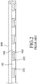
- FIGs. 1 and 2 show an existing roast pan 100 used for removal of grease drippings during cooking meat.
- the roast pan 100 includes a plurality of oil discharge holes 101 extending through top and bottom surfaces of the roast pan 100, and a plurality of protrusions 102 extending downwardly and adjoining the oil discharge holes 101.
- the roast pan 100 may be unable to drain the grease drippings quickly, so that the grease drippings may be overheated and generate a considerable amount of smoke. Further, the grease drippings are easily stuck in dead spaces of the protrusions 102, causing difficulties for cleaning the roast pan 100.
- one object of the disclosure is to provide a cooking device that can alleviate at least one of the drawbacks of the prior art.
- a cooking device includes a heating unit and an oil discharge roast pan mounted on the heating unit.
- the oil discharge roast pan includes a pan body, a plurality of oil discharge holes extending through top and bottom surfaces of the pan body, and a plurality of protrusions protruding downwardly from the bottom surface.
- the pan body further comprises a plurality of food support portions which are spaced apart from each other to cooperatively define the oil discharge holes, and the protrusions are disposed under the food support portions.
- the protrusions and the food support portions are integrally formed with the pan body.
- the protrusions are arranged in multiple rows, and the protrusions in each row are linearly disposed under one of the food support portions.
- the oil discharge roast pan further comprises a mounting rib disposed under the bottom surface of the pan body and connected to the food support portions.
- the mounting rib is defined with a mounting groove that extends along a length direction of the mounting rib and that has an opening facing downwardly.
- the heating unit comprises a heating member that extends along the mounting groove and that is embedded in the mounting groove.
- each of the mounting rib and the mounting groove is U-shaped.
- each of the protrusions has a top side edge adjoining a boundary of one of the oil discharge holes.
- each of the protrusions tapers downwardly from the bottom surface.
- each of the protrusions has a hemispherical, conical, or pyramidal shape.
- an oil discharge roast pan comprises a pan body, a plurality of oil discharge holes extending through top and bottom surfaces of the pan body, and a plurality of protrusions protruding downwardly from the bottom surface.
- the pan body further comprises a plurality of food support portions which are spaced apart from each other to cooperatively define the oil discharge holes, and the protrusions are disposed under the food support portions.
- the protrusions and the food support portions are integrally formed with the pan body.
- each of the protrusions has a top side edge adjoining a boundary of one of the oil discharge holes.
- the oil discharge roast pan further comprises a mounting rib disposed under the bottom surface of the pan body and connected to the food support portions.
- the mounting rib is defined with a mounting groove that extends along a length direction of the mounting rib and that has an opening facing downwardly.
- the mounting groove is configured for a heating unit to be embedded therein.
- the protrusions each have a cross-section gradually decreasing downwardly from the bottom surface.
- each of the protrusions has a hemispherical, conical or pyramidal shape.
- each of the food support portions is formed between two of the oil discharge holes.
- Each of the protrusions has two opposite top side edges respectively adjoining the boundaries of two of the oil discharge holes.
- the protrusions are arranged in multiple rows, and the protrusions in each row are disposed under one of the food support portions at intervals.
- the oil discharge roast pan has an efficient grease collecting effect and can rapidly discharge grease drippings.
- the problem of roasting smoke encountered in the prior art can thus be considerably alleviated.
- the oil discharge roast pan has a bottom surface with an open-type design that greatly reduce the amount of dead spaces, the oil discharge roast pan can be easily cleaned and preserved.
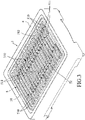
- FIGs. 3 to 5 show a cooking device 3 according to an embodiment of the disclosure.
- the cooking device 3 includes a heating unit 4 and an oil discharge roast pan 5 mounted to and heated by the heating unit 4 for cooking food.
- the oil discharge roast pan 5 includes a pan body 51, a plurality of oil discharge holes 510 extending through top and bottom surfaces 512, 513 of the pan body 51, a mounting rib 52 disposed under the bottom surface 513 of the pan body 51, and a plurality of protrusions 53 protruding downwardly from the bottom surface 513 of the pan body 51.
- the pan body 51 further includes a plurality of spaced-apart food support portions 511 which are spaced apart from each other to cooperatively define the oil discharge holes 510. Specifically, each of the food support portions 511 is formed between two of the oil discharge holes 510.
- the mounting rib 52 is connected to the food support portions 511, and is defined with a mounting groove 520 that extends along a length direction of the mounting rib 52 and that has an opening facing downwardly.
- the heating unit 4 includes a heating member 41 that extends along the mounting groove 520 and that is embedded in the mounting groove 520.
- Each protrusion 53 is disposed under one of the food support portions 511, and has a top side edge 530 connecting or adjoining a boundary of at least one of the oil discharge holes 510.
- the configuration of each protrusion 53 is arranged to taper downwardly from the bottom surface 513 of the pan body 51.
- each of the protrusions 53 has two opposite outer surfaces 531 with top ends which respectively adjoin boundaries of two of the oil discharge holes 510.
- the two opposite outer surfaces 531 extend downwardly in a converging manner.
- the protrusions 53 are arranged in multiple rows.
- the protrusions 53 in each row are linearly disposed under one of the food support portions 511 at intervals.
- each protrusion 53 has a cross-section gradually decreasing downwardly from the bottom surface 513.
- the protrusions 53 and the food support portions 511 are integrally formed with the pan body 51.
- the pan body 51 further includes a peripheral portion 514 surrounding the food support portions 511 and the oil discharge holes 510, and a plurality of spaced apart auxiliary protrusions 53' which project downwardly from the peripheral portion 514.
- Each auxiliary protrusion 53' has an outer surface adjoining a boundary of one of the oil discharge holes 510 and extends downwardly in an inclining manner with respect to a plane perpendicular to the peripheral portion 514.
- Each of the protrusions 53 and the auxiliary protrusions 53' has a pyramidal shape.
- each protrusion 53 may have one outer surface to adjoin the boundary of one oil discharge hole 510 and extend downwardly in an inclining manner with respect to a plane perpendicularly intersecting the corresponding one of the food support portions 511 at the boundary.
- each protrusion 53 directly adjoins the boundaries of two oil discharge holes 510, the embodiment is not limited thereto. A spacing may be present between the top side edge 530 of each protrusion 53 and the boundaries of the oil discharge holes 510 as long as each protrusion 53 is able to collect and drop the grease drippings downwardly from the pan body 51.
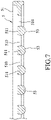
- FIGs. 6 and 7 show another embodiment in which each protrusion 53 has a hemispherical shape.
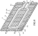
- FIGs. 8 and 9 show still another embodiment in which each protrusion 53 has a conical shape.
- the efficient oil collecting effect produced by the protrusions 53 enables the grease flowing through the oil discharge holes 510 to accumulate rapidly and to form a large quantity of drippings that can easily fall downward and quickly escape from the oil discharge roast pan 5.
- the roasting smoke problem encountered in the prior art is therefore avoided.
- the bottom surface 513 of the pan body 51 is provided with an open-type design that can greatly reduce the amount of dead spaces capable of retaining grease, the pan body 51 can be easily cleaned and preserved.
Landscapes
- Engineering & Computer Science (AREA)
- Food Science & Technology (AREA)
- Manufacturing & Machinery (AREA)
- Chemical & Material Sciences (AREA)
- Combustion & Propulsion (AREA)
- Mechanical Engineering (AREA)
- General Engineering & Computer Science (AREA)
- Baking, Grill, Roasting (AREA)
- Frying-Pans Or Fryers (AREA)
Description
- The disclosure relates to a cooking device including an oil discharge roast pan.
- Roasted food smell is usually very enticing. Therefore, roasters have become desirable cooking utensils for home and restaurant kitchens. A roaster generally includes a base, a roast pan disposed on the base, and a heating unit mounted on the base to heat the roast pan.
-
FIGs. 1 and2 show an existingroast pan 100 used for removal of grease drippings during cooking meat. Theroast pan 100 includes a plurality ofoil discharge holes 101 extending through top and bottom surfaces of theroast pan 100, and a plurality ofprotrusions 102 extending downwardly and adjoining theoil discharge holes 101. However, theroast pan 100 may be unable to drain the grease drippings quickly, so that the grease drippings may be overheated and generate a considerable amount of smoke. Further, the grease drippings are easily stuck in dead spaces of theprotrusions 102, causing difficulties for cleaning theroast pan 100. - Document
DE 19924299 A1 discloses a grilling device with a grate comprising downwardly facing protrusions. - Therefore, one object of the disclosure is to provide a cooking device that can alleviate at least one of the drawbacks of the prior art.
- According to the invention, a cooking device includes a heating unit and an oil discharge roast pan mounted on the heating unit. The oil discharge roast pan includes a pan body, a plurality of oil discharge holes extending through top and bottom surfaces of the pan body, and a plurality of protrusions protruding downwardly from the bottom surface.
- According to the invention, the pan body further comprises a plurality of food support portions which are spaced apart from each other to cooperatively define the oil discharge holes, and the protrusions are disposed under the food support portions.
- In one embodiment, the protrusions and the food support portions are integrally formed with the pan body.
- In one embodiment, the protrusions are arranged in multiple rows, and the protrusions in each row are linearly disposed under one of the food support portions.
- In one embodiment, the oil discharge roast pan further comprises a mounting rib disposed under the bottom surface of the pan body and connected to the food support portions. The mounting rib is defined with a mounting groove that extends along a length direction of the mounting rib and that has an opening facing downwardly. The heating unit comprises a heating member that extends along the mounting groove and that is embedded in the mounting groove.
- In one embodiment, each of the mounting rib and the mounting groove is U-shaped.
- In one embodiment, each of the protrusions has a top side edge adjoining a boundary of one of the oil discharge holes.
- According to the invention, each of the protrusions tapers downwardly from the bottom surface.
- According to the invention, each of the protrusions has a hemispherical, conical, or pyramidal shape.
- According to another object of the disclosure, an oil discharge roast pan is provided. The oil discharge roast pan comprises a pan body, a plurality of oil discharge holes extending through top and bottom surfaces of the pan body, and a plurality of protrusions protruding downwardly from the bottom surface.
- According to the invention, the pan body further comprises a plurality of food support portions which are spaced apart from each other to cooperatively define the oil discharge holes, and the protrusions are disposed under the food support portions.
- In one embodiment, the protrusions and the food support portions are integrally formed with the pan body.
- In one embodiment, each of the protrusions has a top side edge adjoining a boundary of one of the oil discharge holes.
- In one embodiment, the oil discharge roast pan further comprises a mounting rib disposed under the bottom surface of the pan body and connected to the food support portions. The mounting rib is defined with a mounting groove that extends along a length direction of the mounting rib and that has an opening facing downwardly. The mounting groove is configured for a heating unit to be embedded therein.
- According to the invention, the protrusions each have a cross-section gradually decreasing downwardly from the bottom surface.
- According to the invention, each of the protrusions has a hemispherical, conical or pyramidal shape.
- In one embodiment, each of the food support portions is formed between two of the oil discharge holes. Each of the protrusions has two opposite top side edges respectively adjoining the boundaries of two of the oil discharge holes.
- In one embodiment, the protrusions are arranged in multiple rows, and the protrusions in each row are disposed under one of the food support portions at intervals.
- By virtue of the particular structural design of the protrusions protruding downwardly from the bottom surface of the oil discharge roast pan of the disclosure, the oil discharge roast pan has an efficient grease collecting effect and can rapidly discharge grease drippings. The problem of roasting smoke encountered in the prior art can thus be considerably alleviated. In addition, since the oil discharge roast pan has a bottom surface with an open-type design that greatly reduce the amount of dead spaces, the oil discharge roast pan can be easily cleaned and preserved.
- Other features and advantages of the disclosure will become apparent in the following detailed description of the embodiments with reference to the accompanying drawings, of which:
-
FIG. 1 is a perspective view illustrating an existing oil discharge roast pan; -
FIG. 2 is a partially cross-sectional view of the existing oil discharge roast pan; -
FIG. 3 is a perspective view illustrating an embodiment of a cooking device according to the invention; -
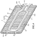
FIG. 4 is a bottom view illustrating an oil discharge roast pan of the cooking device; -
FIG. 5 is a partially cross-sectional view ofFIG. 4 ; -
FIG. 6 is a bottom view illustrating an oil discharge roast pan in another embodiment of a cooking device according to the invention; -
FIG. 7 is a partially cross-sectional view ofFIG. 6 ; -
FIG. 8 is a bottom view illustrating an oil discharge roast pan in still another embodiment of a cooking device according to the disclosure; and -
FIG. 9 is a partially cross-sectional view ofFIG. 8 . -
FIGs. 3 to 5 show a cooking device 3 according to an embodiment of the disclosure. The cooking device 3 includes aheating unit 4 and an oildischarge roast pan 5 mounted to and heated by theheating unit 4 for cooking food. - The oil
discharge roast pan 5 includes apan body 51, a plurality ofoil discharge holes 510 extending through top andbottom surfaces pan body 51, amounting rib 52 disposed under thebottom surface 513 of thepan body 51, and a plurality ofprotrusions 53 protruding downwardly from thebottom surface 513 of thepan body 51. - The
pan body 51 further includes a plurality of spaced-apartfood support portions 511 which are spaced apart from each other to cooperatively define theoil discharge holes 510. Specifically, each of thefood support portions 511 is formed between two of theoil discharge holes 510. - The
mounting rib 52 is connected to thefood support portions 511, and is defined with amounting groove 520 that extends along a length direction of themounting rib 52 and that has an opening facing downwardly. In this embodiment, theheating unit 4 includes aheating member 41 that extends along themounting groove 520 and that is embedded in themounting groove 520. - Each
protrusion 53 is disposed under one of thefood support portions 511, and has atop side edge 530 connecting or adjoining a boundary of at least one of theoil discharge holes 510. The configuration of eachprotrusion 53 is arranged to taper downwardly from thebottom surface 513 of thepan body 51. In this embodiment, each of theprotrusions 53 has two oppositeouter surfaces 531 with top ends which respectively adjoin boundaries of two of theoil discharge holes 510. The two oppositeouter surfaces 531 extend downwardly in a converging manner. Theprotrusions 53 are arranged in multiple rows. Theprotrusions 53 in each row are linearly disposed under one of thefood support portions 511 at intervals. In this embodiment, eachprotrusion 53 has a cross-section gradually decreasing downwardly from thebottom surface 513. Theprotrusions 53 and thefood support portions 511 are integrally formed with thepan body 51. - In addition, the
pan body 51 further includes aperipheral portion 514 surrounding thefood support portions 511 and theoil discharge holes 510, and a plurality of spaced apart auxiliary protrusions 53' which project downwardly from theperipheral portion 514. Each auxiliary protrusion 53' has an outer surface adjoining a boundary of one of theoil discharge holes 510 and extends downwardly in an inclining manner with respect to a plane perpendicular to theperipheral portion 514. Each of theprotrusions 53 and the auxiliary protrusions 53' has a pyramidal shape. - While two opposite
outer surfaces 531 of eachprotrusion 53 respectively adjoin the boundaries of two oil discharge holes 510 in this embodiment, according to other embodiments, when more than one row of theprotrusions 53 are disposed under eachfood support portion 511, eachprotrusion 53 may have one outer surface to adjoin the boundary of oneoil discharge hole 510 and extend downwardly in an inclining manner with respect to a plane perpendicularly intersecting the corresponding one of thefood support portions 511 at the boundary. - When food is cooked by the cooking device 3, grease drippings from the food being cooked flow through the oil discharge holes 510 to the
bottom surface 513 of thepan body 51 and are then guided by theouter surfaces 531 of theprotrusions 53 to flow downward. Theprotrusions 53 that taper downwardly can collect a large quantity of the grease drippings thereunder. The large quantity of the grease drippings are formed into droplets which can easily drop downward and escape from the high temperature oildischarge roast pan 5. The problem of producing considerable amount of smoke due to overheating can therefore be avoided. - Further, the arrangement of the
protrusions 53 that taper downwardly eliminates formation of dead spaces at thebottom surface 513 of thepan body 51. Therefore, the grease drippings can easily escape from thepan body 51 and thepan body 51 can be cleaned conveniently. While thetop side edge 530 of eachprotrusion 53 directly adjoins the boundaries of two oil discharge holes 510, the embodiment is not limited thereto. A spacing may be present between thetop side edge 530 of eachprotrusion 53 and the boundaries of the oil discharge holes 510 as long as eachprotrusion 53 is able to collect and drop the grease drippings downwardly from thepan body 51. -
FIGs. 6 and7 show another embodiment in which eachprotrusion 53 has a hemispherical shape. -
FIGs. 8 and9 show still another embodiment in which eachprotrusion 53 has a conical shape. - In conclusion, by virtue of the unique structural design of the
protrusions 53 protruding downwardly from thebottom surface 513 of thepan body 51, during the process of roasting food, the efficient oil collecting effect produced by theprotrusions 53 enables the grease flowing through the oil discharge holes 510 to accumulate rapidly and to form a large quantity of drippings that can easily fall downward and quickly escape from the oildischarge roast pan 5. The roasting smoke problem encountered in the prior art is therefore avoided. Further, because thebottom surface 513 of thepan body 51 is provided with an open-type design that can greatly reduce the amount of dead spaces capable of retaining grease, thepan body 51 can be easily cleaned and preserved. - In the description above, for the purposes of explanation, numerous specific details have been set forth in order to provide a thorough understanding of the embodiment. It will be apparent, however, to one skilled in the art, that one or more other embodiments may be practiced without some of these specific details. It should also be appreciated that reference throughout this specification to "one embodiment," "an embodiment," an embodiment with an indication of an ordinal number and so forth means that a particular feature, structure, or characteristic may be included in the practice of the disclosure. It should be further appreciated that in the description, various features are sometimes grouped together in a single embodiment, figure, or description thereof for the purpose of streamlining the disclosure and aiding in the understanding of various inventive aspects, and that one or more features or specific details from one embodiment may be practiced together with one or more features or specific details from another embodiment, where appropriate, in the practice of the disclosure.
Claims (11)
- A cooking device, comprising:a heating unit (4); andan oil discharge roast pan (5) mounted on the heating unit (4) to be heated up by the heating unit (4), the oil discharge roast pan (5) comprising a pan body (51), a plurality of oil discharge holes (510) extending through top and bottom surfaces (512, 513) of the pan body (51), and a plurality of protrusions (53) protruding downwardly from the bottom surface (513),the pan body (51) including a plurality of food support portions (511) which are spaced apart from each other to cooperatively define the oil discharge holes (510), the protrusions (53) being disposed under the food support portions (511), each of the protrusions (53) tapering downwardly from the bottom surface (513), the cooking device being characterized in that each of the protrusions (53) of said oil discharge roast pan (5) has a shape selected from a hemispherical shape, a conical shape, and a pyramidal shape.
- The cooking device as claimed in claim 1, characterized in that the protrusions (53) and the food support portions (511) are integrally formed with the pan body (51).
- The cooking device as claimed in claims 1 or 2, characterized in that the protrusions (53) are arranged in multiple rows, and the protrusions (53) in each row are linearly disposed under one of the food support portions (511).
- The cooking device as claimed in any one of claims 1 to 3, characterized in that:the oil discharge roast pan (5) further comprises a mounting rib (52) disposed under the bottom surface (513) of the pan body (51) and connected to the food support portions (511);the mounting rib (52) is defined with a mounting groove (520) that extends along a length direction of the mounting rib (52) and that has an opening facing downwardly; andthe heating unit (4) comprises a heating member (41) that extends along the mounting groove (520) and that is embedded in the mounting groove (520).
- The cooking device as claimed in claim 4, characterized in that each of the mounting rib (52) and the mounting groove (520) is U-shaped.
- The cooking device as claimed in any one of Claims 1 to 5, characterized in that each of the protrusions (53) has a top side edge (530) adjoining a boundary of one of the oil discharge holes (510).
- An oil discharge roast pan (5), comprising a pan body (51), a plurality of oil discharge holes (510) extending through top and bottom surfaces (512, 513) of the pan body (51), and a plurality of protrusions (53) protruding and tapering downwardly from the bottom surface (513), the pan body (51) further including a plurality of food support portions (511) which are spaced apart from each other to cooperatively define the oil discharge holes (510), the protrusions (53) being disposed under the food support portions (511),
said oil discharge roast pan (5) being characterized in that each of the protrusions (53) has a shape selected from a hemispherical shape, a conical shape, and a pyramidal shape. - The oil discharge roast pan (5) as claimed in claim 7, characterized in that the protrusions (53) and the food support portions (511) are integrally formed with the pan body (51).
- The oil discharge roast pan (5) as claimed in claims 7 or 8, characterized in that each of the protrusions (53) has a top side edge (530) adjoining a boundary of one of the oil discharge holes (510).
- The oil discharge roast pan (5) as claimed in any one of claims 7 to 9, further comprising a mounting rib (52) disposed under the bottom surface (513) of the pan body (51) and connected to the food support portions (511), characterized in that the mounting rib (52) is defined with a mounting groove (520) that extends along a length direction of the mounting rib (52) and that has an opening facing downwardly, and the mounting groove (520) is configured for a heating unit (4) to be embedded therein.
- The oil discharge roast pan (5) as claimed in any one of claims 7 to 10, characterized in that each of the food support portions (511) is formed between two of the oil discharge holes (510), and each of the protrusions (53) has two opposite top side edges (530) respectively adjoining the boundaries of two of the oil discharge holes (510).
Applications Claiming Priority (1)
| Application Number | Priority Date | Filing Date | Title |
|---|---|---|---|
| CN201811190227.1A CN111035278B (en) | 2018-10-12 | 2018-10-12 | Frying and roasting device and oil discharging and roasting tray thereof |
Publications (2)
| Publication Number | Publication Date |
|---|---|
| EP3636120A1 EP3636120A1 (en) | 2020-04-15 |
| EP3636120B1 true EP3636120B1 (en) | 2022-08-24 |
Family
ID=68242443
Family Applications (1)
| Application Number | Title | Priority Date | Filing Date |
|---|---|---|---|
| EP19202176.4A Active EP3636120B1 (en) | 2018-10-12 | 2019-10-09 | Oil discharge roast pan and cooking device having same |
Country Status (3)
| Country | Link |
|---|---|
| US (1) | US11622652B2 (en) |
| EP (1) | EP3636120B1 (en) |
| CN (1) | CN111035278B (en) |
Families Citing this family (3)
| Publication number | Priority date | Publication date | Assignee | Title |
|---|---|---|---|---|
| US10638879B2 (en) * | 2015-06-11 | 2020-05-05 | Whirlpool Corporation | Grilling appliance having air jacket for smoke removal and ventilation |
| CN111528708B (en) * | 2020-05-09 | 2021-05-11 | 安徽永耀电器有限公司 | Frying pan capable of removing juice |
| US11882961B1 (en) | 2023-01-18 | 2024-01-30 | Sharkninja Operating Llc | Cover plate for cooking devices |
Family Cites Families (19)
| Publication number | Priority date | Publication date | Assignee | Title |
|---|---|---|---|---|
| US4979440A (en) * | 1989-03-30 | 1990-12-25 | Latour Joseph L | BBQ grill insert |
| US5355779A (en) | 1992-07-10 | 1994-10-18 | Breville R & D Pty Limited | Griller |
| US5323693A (en) * | 1993-03-25 | 1994-06-28 | Anchor Hocking Corporation | Combination frying pan insert and frying pan |
| JPH07231853A (en) | 1993-12-27 | 1995-09-05 | Arco Kogyo Kk | Heat cooking device |
| US5719377A (en) * | 1994-08-15 | 1998-02-17 | Sunbeam Products, Inc. | Dual heating element electric grill having a smoker heating element for vaporizing grease and juices from foodstuff |
| CA2208037A1 (en) * | 1997-07-02 | 1999-01-02 | Laura E. Child | The meatball wizard |
| DE19924299B4 (en) * | 1999-05-27 | 2008-06-12 | BSH Bosch und Siemens Hausgeräte GmbH | electric grill |
| JP2003265327A (en) * | 2002-03-14 | 2003-09-24 | Hitachi Hometec Ltd | Heating cooker |
| KR20040088232A (en) * | 2003-04-09 | 2004-10-16 | 장희춘 | A baked fish |
| US7810487B2 (en) * | 2005-12-01 | 2010-10-12 | W.C. Bradley Company | Apparatus and methods for providing an improved cooking grate for an outdoor cooking grill |
| CN101325897B (en) * | 2005-12-07 | 2010-09-22 | 李珠镐 | Gridiron |
| US8631739B2 (en) * | 2006-06-22 | 2014-01-21 | Kenyon International, Inc. | Grill |
| AU2011343681B2 (en) * | 2010-12-17 | 2015-12-10 | W.C. Bradley Co. | Cooking grate and cooking apparatus |
| US8813738B2 (en) * | 2011-03-03 | 2014-08-26 | W.C. Bradley Co. | Cooking grate assembly and cooking apparatus |
| EP2745755B1 (en) * | 2012-12-21 | 2019-07-31 | ACS Coating Systems GmbH | Grill pan |
| CN203709855U (en) * | 2014-01-28 | 2014-07-16 | 宁波市威捷电器有限公司 | Oil draining ovenware |
| CN204813492U (en) * | 2015-06-29 | 2015-12-02 | 宁波安提西炊具有限公司 | Healthy energy -conserving oven |
| KR101565326B1 (en) * | 2015-07-09 | 2015-11-04 | 조은미 | Roast plate |
| KR101803836B1 (en) * | 2017-03-09 | 2017-12-04 | 최승혁 | Electric roaster equipped recirculation and purification system |
-
2018
- 2018-10-12 CN CN201811190227.1A patent/CN111035278B/en active Active
-
2019
- 2019-10-08 US US16/596,420 patent/US11622652B2/en active Active
- 2019-10-09 EP EP19202176.4A patent/EP3636120B1/en active Active
Also Published As
| Publication number | Publication date |
|---|---|
| EP3636120A1 (en) | 2020-04-15 |
| CN111035278B (en) | 2022-08-09 |
| US11622652B2 (en) | 2023-04-11 |
| CN111035278A (en) | 2020-04-21 |
| US20200113381A1 (en) | 2020-04-16 |
Similar Documents
| Publication | Publication Date | Title |
|---|---|---|
| EP3636120B1 (en) | Oil discharge roast pan and cooking device having same | |
| US7415922B2 (en) | Grill pan | |
| US3972318A (en) | Utensil for oven cooking | |
| CN107072441B (en) | Insert for an air fryer, device comprising such an insert | |
| CA2140839C (en) | Cooking grid | |
| US20190282028A1 (en) | Grill pan for direct fired roast | |
| WO2011104332A1 (en) | A griddle pan | |
| US2042773A (en) | Broiler | |
| KR100940370B1 (en) | The meat roasted with a burning prevention function | |
| DE102006011413A1 (en) | Electric grill for use in open air has serpentine heating element mounted in casing, on top of which grill plates fit which have fat channels with holes which drop fat on to drip pan below the heating element | |
| KR200466340Y1 (en) | Grill for grilling | |
| KR102125481B1 (en) | Cast iron pan cookware | |
| US20200237144A1 (en) | Heatproof carrier for food preparation and method | |
| GB2220838A (en) | A cooking tray | |
| CN111657752A (en) | Barbecue oven and baking tray thereof | |
| US20100037885A1 (en) | Structure of meat roasting net for a roasting stove | |
| KR102100597B1 (en) | multi-slope grill grate | |
| CN210784023U (en) | Barbecue plate | |
| CN209750789U (en) | Air fryer | |
| CN209984063U (en) | Cooking utensil | |
| KR102019610B1 (en) | A barbecue grill | |
| KR102076908B1 (en) | A barbecue grill | |
| EP1444934B1 (en) | Grill unit and cooking apparatus with the same | |
| JP3208285U (en) | kitchenware | |
| JP5600793B2 (en) | Grilled meat plate and electric cooker using the same |
Legal Events
| Date | Code | Title | Description |
|---|---|---|---|
| PUAI | Public reference made under article 153(3) epc to a published international application that has entered the european phase |
Free format text: ORIGINAL CODE: 0009012 |
|
| STAA | Information on the status of an ep patent application or granted ep patent |
Free format text: STATUS: THE APPLICATION HAS BEEN PUBLISHED |
|
| AK | Designated contracting states |
Kind code of ref document: A1 Designated state(s): AL AT BE BG CH CY CZ DE DK EE ES FI FR GB GR HR HU IE IS IT LI LT LU LV MC MK MT NL NO PL PT RO RS SE SI SK SM TR |
|
| AX | Request for extension of the european patent |
Extension state: BA ME |
|
| STAA | Information on the status of an ep patent application or granted ep patent |
Free format text: STATUS: REQUEST FOR EXAMINATION WAS MADE |
|
| 17P | Request for examination filed |
Effective date: 20200625 |
|
| RBV | Designated contracting states (corrected) |
Designated state(s): AL AT BE BG CH CY CZ DE DK EE ES FI FR GB GR HR HU IE IS IT LI LT LU LV MC MK MT NL NO PL PT RO RS SE SI SK SM TR |
|
| STAA | Information on the status of an ep patent application or granted ep patent |
Free format text: STATUS: EXAMINATION IS IN PROGRESS |
|
| 17Q | First examination report despatched |
Effective date: 20210331 |
|
| GRAP | Despatch of communication of intention to grant a patent |
Free format text: ORIGINAL CODE: EPIDOSNIGR1 |
|
| STAA | Information on the status of an ep patent application or granted ep patent |
Free format text: STATUS: GRANT OF PATENT IS INTENDED |
|
| INTG | Intention to grant announced |
Effective date: 20220315 |
|
| GRAS | Grant fee paid |
Free format text: ORIGINAL CODE: EPIDOSNIGR3 |
|
| GRAA | (expected) grant |
Free format text: ORIGINAL CODE: 0009210 |
|
| STAA | Information on the status of an ep patent application or granted ep patent |
Free format text: STATUS: THE PATENT HAS BEEN GRANTED |
|
| AK | Designated contracting states |
Kind code of ref document: B1 Designated state(s): AL AT BE BG CH CY CZ DE DK EE ES FI FR GB GR HR HU IE IS IT LI LT LU LV MC MK MT NL NO PL PT RO RS SE SI SK SM TR |
|
| REG | Reference to a national code |
Ref country code: CH Ref legal event code: EP |
|
| REG | Reference to a national code |
Ref country code: DE Ref legal event code: R096 Ref document number: 602019018592 Country of ref document: DE |
|
| REG | Reference to a national code |
Ref country code: IE Ref legal event code: FG4D |
|
| REG | Reference to a national code |
Ref country code: AT Ref legal event code: REF Ref document number: 1513083 Country of ref document: AT Kind code of ref document: T Effective date: 20220915 |
|
| REG | Reference to a national code |
Ref country code: LT Ref legal event code: MG9D |
|
| REG | Reference to a national code |
Ref country code: NL Ref legal event code: MP Effective date: 20220824 |
|
| PG25 | Lapsed in a contracting state [announced via postgrant information from national office to epo] |
Ref country code: SE Free format text: LAPSE BECAUSE OF FAILURE TO SUBMIT A TRANSLATION OF THE DESCRIPTION OR TO PAY THE FEE WITHIN THE PRESCRIBED TIME-LIMIT Effective date: 20220824 Ref country code: RS Free format text: LAPSE BECAUSE OF FAILURE TO SUBMIT A TRANSLATION OF THE DESCRIPTION OR TO PAY THE FEE WITHIN THE PRESCRIBED TIME-LIMIT Effective date: 20220824 Ref country code: PT Free format text: LAPSE BECAUSE OF FAILURE TO SUBMIT A TRANSLATION OF THE DESCRIPTION OR TO PAY THE FEE WITHIN THE PRESCRIBED TIME-LIMIT Effective date: 20221226 Ref country code: NO Free format text: LAPSE BECAUSE OF FAILURE TO SUBMIT A TRANSLATION OF THE DESCRIPTION OR TO PAY THE FEE WITHIN THE PRESCRIBED TIME-LIMIT Effective date: 20221124 Ref country code: NL Free format text: LAPSE BECAUSE OF FAILURE TO SUBMIT A TRANSLATION OF THE DESCRIPTION OR TO PAY THE FEE WITHIN THE PRESCRIBED TIME-LIMIT Effective date: 20220824 Ref country code: LV Free format text: LAPSE BECAUSE OF FAILURE TO SUBMIT A TRANSLATION OF THE DESCRIPTION OR TO PAY THE FEE WITHIN THE PRESCRIBED TIME-LIMIT Effective date: 20220824 Ref country code: LT Free format text: LAPSE BECAUSE OF FAILURE TO SUBMIT A TRANSLATION OF THE DESCRIPTION OR TO PAY THE FEE WITHIN THE PRESCRIBED TIME-LIMIT Effective date: 20220824 Ref country code: FI Free format text: LAPSE BECAUSE OF FAILURE TO SUBMIT A TRANSLATION OF THE DESCRIPTION OR TO PAY THE FEE WITHIN THE PRESCRIBED TIME-LIMIT Effective date: 20220824 |
|
| REG | Reference to a national code |
Ref country code: AT Ref legal event code: MK05 Ref document number: 1513083 Country of ref document: AT Kind code of ref document: T Effective date: 20220824 |
|
| PG25 | Lapsed in a contracting state [announced via postgrant information from national office to epo] |
Ref country code: PL Free format text: LAPSE BECAUSE OF FAILURE TO SUBMIT A TRANSLATION OF THE DESCRIPTION OR TO PAY THE FEE WITHIN THE PRESCRIBED TIME-LIMIT Effective date: 20220824 Ref country code: IS Free format text: LAPSE BECAUSE OF FAILURE TO SUBMIT A TRANSLATION OF THE DESCRIPTION OR TO PAY THE FEE WITHIN THE PRESCRIBED TIME-LIMIT Effective date: 20221224 Ref country code: HR Free format text: LAPSE BECAUSE OF FAILURE TO SUBMIT A TRANSLATION OF THE DESCRIPTION OR TO PAY THE FEE WITHIN THE PRESCRIBED TIME-LIMIT Effective date: 20220824 Ref country code: GR Free format text: LAPSE BECAUSE OF FAILURE TO SUBMIT A TRANSLATION OF THE DESCRIPTION OR TO PAY THE FEE WITHIN THE PRESCRIBED TIME-LIMIT Effective date: 20221125 |
|
| PG25 | Lapsed in a contracting state [announced via postgrant information from national office to epo] |
Ref country code: SM Free format text: LAPSE BECAUSE OF FAILURE TO SUBMIT A TRANSLATION OF THE DESCRIPTION OR TO PAY THE FEE WITHIN THE PRESCRIBED TIME-LIMIT Effective date: 20220824 Ref country code: RO Free format text: LAPSE BECAUSE OF FAILURE TO SUBMIT A TRANSLATION OF THE DESCRIPTION OR TO PAY THE FEE WITHIN THE PRESCRIBED TIME-LIMIT Effective date: 20220824 Ref country code: ES Free format text: LAPSE BECAUSE OF FAILURE TO SUBMIT A TRANSLATION OF THE DESCRIPTION OR TO PAY THE FEE WITHIN THE PRESCRIBED TIME-LIMIT Effective date: 20220824 Ref country code: DK Free format text: LAPSE BECAUSE OF FAILURE TO SUBMIT A TRANSLATION OF THE DESCRIPTION OR TO PAY THE FEE WITHIN THE PRESCRIBED TIME-LIMIT Effective date: 20220824 Ref country code: CZ Free format text: LAPSE BECAUSE OF FAILURE TO SUBMIT A TRANSLATION OF THE DESCRIPTION OR TO PAY THE FEE WITHIN THE PRESCRIBED TIME-LIMIT Effective date: 20220824 Ref country code: AT Free format text: LAPSE BECAUSE OF FAILURE TO SUBMIT A TRANSLATION OF THE DESCRIPTION OR TO PAY THE FEE WITHIN THE PRESCRIBED TIME-LIMIT Effective date: 20220824 |
|
| REG | Reference to a national code |
Ref country code: DE Ref legal event code: R097 Ref document number: 602019018592 Country of ref document: DE |
|
| PG25 | Lapsed in a contracting state [announced via postgrant information from national office to epo] |
Ref country code: SK Free format text: LAPSE BECAUSE OF FAILURE TO SUBMIT A TRANSLATION OF THE DESCRIPTION OR TO PAY THE FEE WITHIN THE PRESCRIBED TIME-LIMIT Effective date: 20220824 Ref country code: MC Free format text: LAPSE BECAUSE OF FAILURE TO SUBMIT A TRANSLATION OF THE DESCRIPTION OR TO PAY THE FEE WITHIN THE PRESCRIBED TIME-LIMIT Effective date: 20220824 Ref country code: EE Free format text: LAPSE BECAUSE OF FAILURE TO SUBMIT A TRANSLATION OF THE DESCRIPTION OR TO PAY THE FEE WITHIN THE PRESCRIBED TIME-LIMIT Effective date: 20220824 |
|
| REG | Reference to a national code |
Ref country code: CH Ref legal event code: PL |
|
| REG | Reference to a national code |
Ref country code: BE Ref legal event code: MM Effective date: 20221031 |
|
| PG25 | Lapsed in a contracting state [announced via postgrant information from national office to epo] |
Ref country code: LU Free format text: LAPSE BECAUSE OF NON-PAYMENT OF DUE FEES Effective date: 20221009 Ref country code: AL Free format text: LAPSE BECAUSE OF FAILURE TO SUBMIT A TRANSLATION OF THE DESCRIPTION OR TO PAY THE FEE WITHIN THE PRESCRIBED TIME-LIMIT Effective date: 20220824 |
|
| PLBE | No opposition filed within time limit |
Free format text: ORIGINAL CODE: 0009261 |
|
| STAA | Information on the status of an ep patent application or granted ep patent |
Free format text: STATUS: NO OPPOSITION FILED WITHIN TIME LIMIT |
|
| PG25 | Lapsed in a contracting state [announced via postgrant information from national office to epo] |
Ref country code: LI Free format text: LAPSE BECAUSE OF NON-PAYMENT OF DUE FEES Effective date: 20221031 Ref country code: CH Free format text: LAPSE BECAUSE OF NON-PAYMENT OF DUE FEES Effective date: 20221031 |
|
| 26N | No opposition filed |
Effective date: 20230525 |
|
| PG25 | Lapsed in a contracting state [announced via postgrant information from national office to epo] |
Ref country code: SI Free format text: LAPSE BECAUSE OF FAILURE TO SUBMIT A TRANSLATION OF THE DESCRIPTION OR TO PAY THE FEE WITHIN THE PRESCRIBED TIME-LIMIT Effective date: 20220824 |
|
| PG25 | Lapsed in a contracting state [announced via postgrant information from national office to epo] |
Ref country code: BE Free format text: LAPSE BECAUSE OF NON-PAYMENT OF DUE FEES Effective date: 20221031 |
|
| PG25 | Lapsed in a contracting state [announced via postgrant information from national office to epo] |
Ref country code: IE Free format text: LAPSE BECAUSE OF NON-PAYMENT OF DUE FEES Effective date: 20221009 |
|
| PGFP | Annual fee paid to national office [announced via postgrant information from national office to epo] |
Ref country code: FR Payment date: 20231026 Year of fee payment: 5 Ref country code: DE Payment date: 20231020 Year of fee payment: 5 |
|
| PG25 | Lapsed in a contracting state [announced via postgrant information from national office to epo] |
Ref country code: HU Free format text: LAPSE BECAUSE OF FAILURE TO SUBMIT A TRANSLATION OF THE DESCRIPTION OR TO PAY THE FEE WITHIN THE PRESCRIBED TIME-LIMIT; INVALID AB INITIO Effective date: 20191009 |
|
| PG25 | Lapsed in a contracting state [announced via postgrant information from national office to epo] |
Ref country code: CY Free format text: LAPSE BECAUSE OF FAILURE TO SUBMIT A TRANSLATION OF THE DESCRIPTION OR TO PAY THE FEE WITHIN THE PRESCRIBED TIME-LIMIT Effective date: 20220824 |