EP3632056B1 - Initalization of a local bus - Google Patents
Initalization of a local bus Download PDFInfo
- Publication number
- EP3632056B1 EP3632056B1 EP18726115.1A EP18726115A EP3632056B1 EP 3632056 B1 EP3632056 B1 EP 3632056B1 EP 18726115 A EP18726115 A EP 18726115A EP 3632056 B1 EP3632056 B1 EP 3632056B1
- Authority
- EP
- European Patent Office
- Prior art keywords
- data
- bus
- data bus
- counter value
- communication
- Prior art date
- Legal status (The legal status is an assumption and is not a legal conclusion. Google has not performed a legal analysis and makes no representation as to the accuracy of the status listed.)
- Active
Links
- 238000000034 method Methods 0.000 claims description 58
- 238000004891 communication Methods 0.000 claims description 44
- 238000012545 processing Methods 0.000 claims description 19
- 230000008859 change Effects 0.000 claims description 11
- 230000008569 process Effects 0.000 description 31
- 101100408464 Caenorhabditis elegans plc-1 gene Proteins 0.000 description 19
- 238000011144 upstream manufacturing Methods 0.000 description 8
- 230000005540 biological transmission Effects 0.000 description 6
- 238000005259 measurement Methods 0.000 description 6
- 230000006870 function Effects 0.000 description 3
- 230000000712 assembly Effects 0.000 description 2
- 238000000429 assembly Methods 0.000 description 2
- 230000001276 controlling effect Effects 0.000 description 2
- 238000010586 diagram Methods 0.000 description 2
- 230000003287 optical effect Effects 0.000 description 2
- 238000012800 visualization Methods 0.000 description 2
- 230000009471 action Effects 0.000 description 1
- 230000006978 adaptation Effects 0.000 description 1
- 238000006243 chemical reaction Methods 0.000 description 1
- 230000008878 coupling Effects 0.000 description 1
- 238000010168 coupling process Methods 0.000 description 1
- 238000005859 coupling reaction Methods 0.000 description 1
- 238000013461 design Methods 0.000 description 1
- 238000005516 engineering process Methods 0.000 description 1
- 238000009434 installation Methods 0.000 description 1
- 238000012423 maintenance Methods 0.000 description 1
- 230000007246 mechanism Effects 0.000 description 1
- 238000012544 monitoring process Methods 0.000 description 1
- 230000010363 phase shift Effects 0.000 description 1
- 230000001105 regulatory effect Effects 0.000 description 1
- 230000003068 static effect Effects 0.000 description 1
- 238000012795 verification Methods 0.000 description 1
Images


Classifications
-
- H—ELECTRICITY
- H04—ELECTRIC COMMUNICATION TECHNIQUE
- H04L—TRANSMISSION OF DIGITAL INFORMATION, e.g. TELEGRAPHIC COMMUNICATION
- H04L12/00—Data switching networks
- H04L12/28—Data switching networks characterised by path configuration, e.g. LAN [Local Area Networks] or WAN [Wide Area Networks]
- H04L12/42—Loop networks
- H04L12/423—Loop networks with centralised control, e.g. polling
-
- H—ELECTRICITY
- H04—ELECTRIC COMMUNICATION TECHNIQUE
- H04L—TRANSMISSION OF DIGITAL INFORMATION, e.g. TELEGRAPHIC COMMUNICATION
- H04L12/00—Data switching networks
- H04L12/28—Data switching networks characterised by path configuration, e.g. LAN [Local Area Networks] or WAN [Wide Area Networks]
- H04L12/40—Bus networks
- H04L12/403—Bus networks with centralised control, e.g. polling
-
- H—ELECTRICITY
- H04—ELECTRIC COMMUNICATION TECHNIQUE
- H04L—TRANSMISSION OF DIGITAL INFORMATION, e.g. TELEGRAPHIC COMMUNICATION
- H04L12/00—Data switching networks
- H04L12/28—Data switching networks characterised by path configuration, e.g. LAN [Local Area Networks] or WAN [Wide Area Networks]
- H04L12/40—Bus networks
- H04L12/40006—Architecture of a communication node
- H04L12/40019—Details regarding a bus master
-
- H—ELECTRICITY
- H04—ELECTRIC COMMUNICATION TECHNIQUE
- H04L—TRANSMISSION OF DIGITAL INFORMATION, e.g. TELEGRAPHIC COMMUNICATION
- H04L12/00—Data switching networks
- H04L12/28—Data switching networks characterised by path configuration, e.g. LAN [Local Area Networks] or WAN [Wide Area Networks]
- H04L12/40—Bus networks
- H04L2012/4026—Bus for use in automation systems
Definitions
- the invention generally relates to the initialization of a local bus, in particular the information query in a local bus by means of relative addressing.
- Automation systems are used in particular to control industrial systems, buildings and means of transport.
- sensors and actuators are usually required to control an automation system. These monitor and control the process carried out by the system.
- the different sensors and actuators of an automation system are often also referred to as automation devices.
- These automation devices can either be connected directly to a controller of the automation system, or can initially be connected to input and output modules, which are often also referred to as I / O modules. These can then in turn be connected directly to the controller.
- the automation devices can either be integrated directly into the I / O modules or can be connected to them via cables or wirelessly.
- An automation system is usually controlled with the help of one or more programmable logic controllers, PLCs.
- the PLCs can be arranged hierarchically or decentrally in an automation system.
- the PLCs have different performance classes so that they can take on different controls and regulations depending on the computing and storage capacity.
- a PLC has inputs, outputs, a Operating system (firmware) and an interface via which a user program can be loaded.
- the user program defines how the outputs are to be switched depending on the inputs.
- the inputs and outputs can be connected to the automation devices and / or the I / O modules and the process carried out by the automation system can be monitored or controlled using the logic stored in the user program.
- the process is monitored by the sensors and the process is controlled by the actuators.
- the controller can also be referred to as a central controller or central unit and takes over the control of at least one automation device or I / O module connected to the controller.
- the direct connection of the automation devices with the at least one controller or the I / O modules with the at least one controller is in the form of parallel wiring, i.e. a line is laid from each automation device or each I / O module to the higher-level controller, very expensive.
- parallel wiring i.e. a line is laid from each automation device or each I / O module to the higher-level controller.
- bus systems are mostly used in automation technology today, with which the automation devices or the I / O modules can be connected to the controller.
- individual groups of automation devices or I / O modules are often first connected to one another using a specialized local bus to form a local bus system and then at least one Participants of this local bus are connected to the bus system that is connected to the controller.
- the local bus system can differ from the bus system that is used to establish the connection with the controller.
- the participant of a group of local bus participants connected to the bus system of the control is often also referred to as the local bus master.
- this local bus master can contain additional logics, circuits or functionalities that are necessary for connection to the bus system of the controller.
- the local bus master itself can also contain a PLC. This participant can also have logic and circuits for implementation between the two bus systems.
- the local bus master can therefore also be designed as a gateway or bus converter and ensures that the data present in the format of one bus system are converted into the format of the local bus system and vice versa. In most cases, but not necessarily, the local bus master specializes in connecting the local bus to the higher-level bus.
- the local buses used are mostly tailored to the specific application requirements of the automation devices or I / O modules or take their special hardware design into account.
- the groups of automation devices or I / O modules of the local bus system mostly form a subgroup of the automation system for performing a special task in the process carried out by the automation system.
- the data exchanged on the buses for the process are also often referred to as local bus data or process data, because this data contains information for regulating or controlling the process carried out by the automation system. These data can include, among other things, measurement data, control data, status data and / or other information. Depending on the bus protocol used, this data can be preceded by other data ( header) or appended ( tail). These other data can contain information relating to the data or information relating to internal communication on the local bus.
- the local bus users connected to a local bus can also be referred to as data bus users because they exchange data on the local bus.
- a data bus subscriber can serve to control or monitor a process, in particular by outputting control signals, for example to actuators, and / or by receiving measurement signals, for example from sensors.
- the data bus subscriber sets the control signals and / or measurement signals in process data for the local bus or vice versa.
- the data bus participants can also be referred to as local bus participants.
- a ring bus is a specialized form of the local bus, such as from U.S. 5,472,347 A known.
- the data bus subscribers for example the automation devices or I / O modules, are each connected to their directly adjacent data bus subscribers and data is passed on in sequence from one data bus subscriber to the other.
- the data transmitted on the local bus can also be referred to as local bus data.
- the data are therefore not sent to all data bus users at the same time, but one after the other, with a data bus user receiving data from its upstream data bus user and forwards data to its downstream data bus user.
- the data bus subscriber can process the received data between receiving the data and forwarding it.
- the ring bus thus has a down stream and an up stream of data.
- the data in a ring bus are usually transmitted in the form of data packets that pass through all data bus participants.
- data packets are provided with an address corresponding to the data bus subscriber, so that the data bus subscriber who has the corresponding address is informed that the data packet is directed to this data bus subscriber.
- the data bus subscribers in ring buses are often addressed according to their physical order in the ring bus, for example in DE 195 45 566 A1 described.
- this makes the self-administration of the ring bus very inflexible and static, especially when new data bus users are added to the ring bus or old ones are replaced.
- the object of the present invention is therefore to provide methods and devices with which flexible addressing is possible even when data bus users are exchanged or when the local bus is initialized, and with which information about the corresponding data bus users is also possible in a simple manner can be collected.
- the method according to the invention for communication with data bus users connected to a local bus, in particular a ring bus, with a local bus master comprises sending a first data packet from the local bus master to all data bus users in order to count communication-ready data bus users in a sequence, the first data packet having a first counter value, which is changed in the sequence by each of the communication-ready data bus participants.
- the first counter value can be a binary value, for example. In other words, the number of data bus users already ready for communication is determined with a first individual data packet. In this communication phase, the data bus participants do not need to be addressed.
- the first data packet for counting can for example be sent in a cycle frame on the local bus.
- a cycle frame can be defined, for example, as a recurring (cyclical), preferably equidistant, time interval in which data can be transmitted on the local bus.
- the cycle frame has, for example, at least one start identifier (SOC) and a time range for the transmission of data.
- SOC start identifier
- Several start identifiers (SOC) of successive cycle frames are advantageously at an equidistant time interval from one another.
- the specified time range is intended for the transmission of the data packets.
- the start identifier (SOC) and the data packets are transmitted via the local bus and pass through all data bus participants.
- the start identifier (SOC) is separate, that is to say can be transmitted as an independent symbol or is advantageously contained in a start data packet (SOC packet).
- one or more data packets are transmitted within the time range of the cycle frame.
- idle data are used in a cycle frame (Idle data) inserted, in particular adjacent to at least one data packet.
- the transmission of the data packets and / or the idle data advantageously brings about an uninterrupted signal on the local bus.
- the signal enables the data bus participants to synchronize themselves with it in terms of time.
- the cycle frame advantageously also has a trailer.
- the trailer has a variable length and follows the time range for data transmission, preferably up to the following start identifier (SOC) of the next cycle frame.
- SOC start identifier
- the trailer advantageously has idle data.
- Each data bus subscriber that is already ready for communication can change the first counter value contained in the data packet upon receipt of the individual data packet, for example increment or decrement it before the data packet or the part of the data packet containing the counter value is sent on to the next data bus subscriber.
- Data bus participants that are not yet ready for communication only pass the data packet through without changing the first counter value.
- a data bus subscriber can be ready for communication if it is clock-synchronized with the local bus and can receive data packets and forward them and is able to carry out processing with the data packets. If the local bus is a ring bus, the data packet is returned to the local bus master from the last data bus participant, regardless of whether it is already ready for communication or not.
- the ring bus can also be closed by a bridge unit that sends the data packets that are received in the downward direction back in the upward direction. This happens either again through all data bus participants so that they can carry out processing again, or past all data bus participants via a bypass connection.
- the local bus master uses the first counter value to know how many data bus users on the local bus are already ready for communication. To query information, the local bus master then generates a number of second data packets. The number of second data packets corresponds to the number of communication-ready data bus users indicated by the first counter value. If the first counter value has indicated, for example, that there are N data bus users ready for communication, then N second data packets are also generated and sent on the local bus, where N is a natural integer.
- the number of second data packets sent by the local bus master to the local bus is intended for a communication-ready data bus subscriber and is assigned to this on the basis of the respective relative position of the communication-ready data bus subscriber within the sequence.
- the communication-ready data bus users have changed the first counter value of the first data packet in a specific order.
- the number of second data packets are preferably sent on the local bus in an order that corresponds to the order in which the first counter value was changed. These second data packets can then be used to address the respective data bus subscribers without their address being known.
- the relative position of the communication-ready data bus subscribers in the local bus is determined and this relative position is then used to address the communication-ready data bus subscribers or to assign and send second data packets to them.
- the relative position of the data bus participants which does not depend on the physical position of the data bus participant but on its readiness for communication, flexible communication and information collection is possible.
- Each data packet of the number of second data packets is assigned to exactly one data bus subscriber who uses this second data packet to forward information to the local bus master.
- the local bus master accordingly addresses the data bus subscribers one after the other in this phase of communication, specifically in the order in which the data bus subscribers changed the first counter value of the first data packet.
- the data packets transmitted on the local bus described here can also be referred to as telegrams.
- the data packets can also be referred to as communication data packets, which are used in particular for programming and / or for controlling and / or for monitoring and / or for identifying at least one data bus participant.
- the data bus subscribers are used to control or monitor a process, in particular by outputting control signals, for example to actuators, and / or by receiving measurement signals, for example from sensors.
- the data bus participant sets the Control signals and / or measurement signals in data for the local bus or vice versa.
- the individual data packet used for the first count is of the same type as the number of second data packets that are generated by the local bus system and sent on the local bus according to the number of the first counter value.
- each data packet of the number of second data packets has a second counter value for assigning the data packet, the second counter value differing in each of the second data packets, ie having a different start value.
- This second counter value is used for the relative addressing of the data bus participants. If a data bus participant recognizes that a second counter value of a data packet used for relative addressing corresponds to a specific reference value, then this data bus participant recognizes that the data packet carrying this second counter value is intended for the data bus participant. In the case of relative addressing, each data bus participant changes the second counter value of each of the number of second data packets. The change can be an incrementing or decrementing of the second counter value.
- the local bus master can be adapted to adapt the second counter value in accordance with the number of data bus users counted, that is to say the first counter value, in such a way that every second counter value differs.
- every second counter value is adapted in such a way that the change in the second counter value by the data bus subscribers causes the second counter value to reach a reference value for only one communication-ready data bus subscriber.
- the reference value can, for example, be the same reference value in all data bus subscribers, so that the second counter value differs accordingly from each data packet. If the second counter value of a data packet reaches the reference value on a communication-ready data bus participant, then this data bus participant knows that the data packet is intended for this data bus participant.
- each data bus subscriber can be designed to carry out a comparison between the second counter value in each data packet from the number of second data packets and a reference value.
- the second Counter value can be represented by a binary representation.
- the data packet sent first of the number of second data packets can have a second counter value which corresponds to the highest binary representation of the possible value range for the second counter value. In other words, the data packet sent first from the number of second data packets has only ones in the second counter value.
- the range of values can depend on the maximum number of data bus participants that can be connected to the local bus.
- the first data bus subscriber increments the second counter value of the data packet sent first from the number of second data packets, then the latter experiences a zero crossing, ie the binary representation has only zeros.
- the reference value can also be a zero crossing of a number of significant last bits. If the reference value of the first data bus participant is zero, the first data bus participant recognizes in the example mentioned here that the data packet is directed to the first data bus participant, ie is assigned to it.
- the second data packet sent to the local bus from the number of second data packets can be intended for the second data bus subscriber, that is to say addressed to the latter. In this data packet, the local bus master can set the second counter value to a value that can be incremented by two data bus users before it crosses zero.
- the second data packet sent out of the number of second data packets can therefore be incremented by the first data bus subscriber and is incremented by the latter to the highest binary representation, ie to a value that has only ones.
- the first data bus participant knows that the data packet is not intended for the first data bus participant and sends it on on the local bus to the next communication-ready data bus participant. This once again increments the second counter value, which has already been incremented once.
- a zero crossing is experienced, so that the second communication-ready data bus subscriber knows that this data packet is intended for the second data bus subscriber.
- the local bus master can assign all data packets of the number of second data packets via the second counter value and its reaching of a reference value to the respective communication-ready data bus subscribers or address or direct them to the respective data bus subscribers. It is clear to the person skilled in the art that even if the incrementing is described here and a zero crossing is assumed as the reference value, this is also the case can be accomplished via a decrement and a one pass. In other words, the second counter value of the data packet sent first is set to zero. If this is decremented, the counter value jumps to only ones. The data packet sent second from the number of data packets then contains a one etc. as the start value for the second counter value correspond to.
- the counter value can preferably be set up to accept a reference value only exactly once, so that the data packets are assigned unambiguously. For example, a comparison with the reference value and then the incrementing / decrementing can also take place first.
- a data bus participant detects that a data packet is directed to the data bus participant because the second counter value in this data packet has reached a reference value that corresponds to a reference value stored in the data bus participant, the data bus participant can write information stored in the data bus participant into a field of the data packet, which is directed to the data bus participant. For example, the data bus participant can write its address in the field. In this way, the local bus master can collect information about the data bus participants.
- this includes comparing the first counter value and the second counter value of at least one data packet from the number of data packets on the local bus master after passing through the local bus, i.e. after the at least one data packet has been processed by each communication-ready data bus participant. If no further data bus subscribers have become ready for communication between the first counting and the return of the data packets to the local bus master, there is a defined relationship between the first counter value and the second counter value. For example, the second counter value of the first data packet from the number of second data packets is equal to the first counter value minus one and the second counter value of the last data packet from the number of second data packets is equal to the reference value, for example equal to zero.
- the second counter value of each data packet from the number of second data packets is then changed exactly once by each data bus subscriber in accordance with the number of data bus subscribers, that is to say the number indicated by the first counter value. If new data bus subscribers have become ready for communication during the first count with the aid of the first counter value and the sending of the number of second data packets, the local bus master cannot recognize a fixed relationship between the first and the second counter value. In this case, the local bus master again sends a single first data packet with a first counter value to the data bus subscribers, so in this case the local bus master again counts the data bus subscribers that are ready for communication.
- the new counter value can be compared with the old counter value. If these match, it can be determined that there was an error in the transmission, or that a data bus participant, although it has signaled readiness for communication, by processing the first data packet with the first counter value, but this is not able to count the number of second data packets to process. If the new first counter value deviates from the old counter value, at least one further data bus subscriber has become ready for communication. In this case, the local bus master sends the number of second data packets again, the number being adapted to the new first counter value and the second counter values of the number of second data packets also being adapted to the new first counter value. This process is repeated until the comparison shows that no further data bus subscribers have meanwhile become ready for communication.
- the local bus master sends out individual first data packets with a first counter value at certain time intervals in order to check the number of data bus users connected to the local bus.
- the local bus master after receiving the number of second data packets, the local bus master again sends a data packet with a first counter value to check whether no further data bus users have become ready for communication in the meantime. Ie the Local bus master verifies the data received in the number of second data packets.
- the above-mentioned object is also achieved by a local bus master of a local bus, in particular a ring bus, with data bus users.
- the local bus master has a means for sending a first data packet to all data bus users, the first data packet being used to count the communication-ready data bus users in a sequence.
- the first data packet can have a first counter value which is changed in the sequence by each communication-ready data bus subscriber. After receiving the first data packet, the local bus master can then use the first counter value of the data packet to determine how many data bus users are already ready for communication.
- the local bus master has a means for sending a number of second data packets, the number of which is based on the first counter value.
- Each of the second data packets is assigned to the communication-ready data bus subscribers in the sequence based on the respective relative position, it being possible for the assignment to take place on the basis of a second counter value.
- the means for transmitting can be a transmitter circuit or a transceiver circuit.
- the circuits can be implemented in an application-specific integrated circuit ( ASIC) or in a field-programmable (logic) gate arrangement ( FPGA).
- the above-mentioned object is also achieved by a method for communication with a local bus master of a local bus, in particular a ring bus, with communication-ready data bus users.
- the method includes receiving a first data packet from a local bus master at a communication-ready data bus subscriber, the first data packet having a first counter value, changing the first counter value in the data packet by the communication-ready data bus subscriber, receiving a number of second data packets, each of the second data packets having one has second counter value.
- the method includes writing information stored in the communication-ready data bus subscriber, for example an address, into a field of a data packet from the number of second data packets that is assigned to the communication-ready data bus subscriber.
- the data bus subscriber can recognize that it has received a data packet from the number of second Data packets is assigned when the data bus subscriber changes the second counter value of the data packet and this then reaches a reference value.
- the second counter value of the number of second data packets is different in each data packet, so that the reference value is only reached exactly once if all communication-ready data bus users change the second counter value of a data packet from the number of second data packets.
- the above-mentioned object is also achieved by a communication-ready data bus subscriber of a local bus, in particular a ring bus, with a local bus master.
- the communication-ready data bus subscriber has a means for receiving a first data packet from a local bus master, the first data packet having a first counter value, a means for changing the first counter value in the first data packet, a means for receiving a number of second data packets, and a means for writing information stored in the communication-ready data bus subscriber, for example an address, into a field of a data packet from the number of second data packets which is assigned to the communication-ready data bus subscriber.
- a local bus system consisting of a local bus master and at least one data bus participant.
- the local bus master has a means for sending a first data packet to all data bus users, the first data packet being used to count the communication-ready data bus users in a sequence.
- the first data packet can have a first counter value which is changed in the sequence by each communication-ready data bus subscriber.
- the local bus master can furthermore have a means for receiving the first data packet with the first counter value changed by each communication-ready data bus subscriber. After receiving the first data packet, the local bus master can then use the first counter value of the data packet to determine how many data bus users are already ready for communication.
- the local bus master has a means for sending a number of second data packets, the number of which is based on the first counter value. Each of the second data packets is assigned based on the respective relative position of the communication-ready data bus subscribers in the sequence, the assignment being made on the basis of the second counter value. The assignment can be accomplished by giving every second data packet a different start value for the second counter value.
- the communication-ready data bus subscriber has a means for receiving the individual first data packet from a local bus master, the first data packet having the first counter value, a means for changing the first counter value in the first data packet, a means for receiving the number of second data packets and a means for writing information stored in the communication-ready data bus subscriber, for example an address, into a field of a data packet from the number of second data packets which is assigned to the communication-ready data bus subscriber.
- the local bus master can have a means for receiving the second data packets changed by the communication-ready data bus subscribers and can read out the data written into the second data packets by the communication-ready data bus subscribers.
- the above object is also achieved by a computer readable medium containing code that causes a computer to carry out one of the methods described herein.
- the code can be stored in the local bus master and / or in the data bus participant.
- the code is stored in a firmware memory of the local bus master or in a memory accessible by the data bus subscribers.
- FIG. 1 shows a schematic block diagram of an automation system. It will be understood by a person skilled in the art that the automation system shown is only an example and all the elements, modules, components, participants and units belonging to the automation system can be configured differently but can still fulfill the basic functionalities described here.
- the automation system shown has a higher-level controller 1, which can be implemented, for example, with a programmable logic controller, PLC.
- PLC programmable logic controller
- Such a PLC 1 basically serves to control and regulate the process carried out by the automation system.
- PLCs 1 in automation systems also take on more extensive functions, such as visualization, alarming and recording of all data relating to the process, and as such the PLC 1 functions as a man-machine interface.
- There are PLCs 1 in different performance classes that have different resources (computing capacity, storage capacity, number and type of inputs and outputs, and interfaces) that enable the PLC 1 to control and regulate the process of the automation system.
- a PLC 1 mostly has a modular structure and consists of individual components, each of which fulfills a different task.
- a PLC 1 usually consists of a central computing module (with one or more main processors and memory modules) and several modules with inputs and outputs. Such modular PLC 1 can easily be expanded by adding assemblies. It depends on the complexity of the process and the complexity of the structure of the automation system which assemblies must be integrated in the PLC 1. In today's automation systems, the PLC 1 is mostly no longer an independent system, but the PLC 1 is connected to the Internet or intranet via appropriate interfaces - not shown here. This means that the PLC 1 is part of a network via which or from which the PLC 1 can receive information, instructions, programming, etc.
- the PLC 1 can receive information about the materials supplied to the process via a connection to a computer located on the intranet or the Internet, so that the process can be optimally controlled by knowing their number or nature, for example. It is also conceivable that the PLC 1 is controlled by a user through access from the intranet or Internet. For example, a user can access the PLC 1 with the aid of a computer, also called a master computer, and check, change or correct its user programming. Accordingly, access to the PLC 1 is possible from one or more remote control rooms or control centers.
- the master computers can optionally have visualization devices for displaying process sequences.
- the PLC 1 is connected to automation devices. In order to keep the wiring effort low, bus systems are used for these connections.
- the PLC 1 is connected to a local bus master 3 of a subordinate local bus system by means of a superordinate bus 2, which in the embodiment shown here can be a field bus.
- a local bus master 3 of a local bus be connected to the higher-level bus 2, as in the exemplary embodiment shown here, but also any other participants - not shown here - that are designed for communication with the PLC 1.
- the higher-level bus 2 is connected to the local bus master 3 in the exemplary embodiment shown here.
- the local bus master 3 has a first interface 4 which is designed in such a way that it can be connected to the higher-level bus 2.
- the interface 4 can have a receptacle in the form of a socket, for example, and the higher-level bus 2 can have a plug that can be received by the socket.
- the plug and the socket can be, for example, a modular plug and a modular socket, i.e. each wire of the higher-level bus 2 is electrically or optically connected to a connection in the modular socket.
- an interface 4 is also familiar with other possibilities of how an interface 4 is to be designed so that the local bus master 3 can be connected electrically or optically to the higher-level bus 2.
- Those skilled in the art are familiar with screw, twist, click or plug connections with the help of which an electrical or optical connection can be established. In most cases, a male connector is received by a female counterpart. This receptacle mostly not only establishes the electrical or optical connection, but also ensures that the two parts are mechanically coupled and can only be detached from one another again with the application of a certain force.
- the higher-level bus 2 is permanently wired to the interface 4.
- the local bus master 3 in the exemplary embodiment shown here has a further second interface in order to connect the local bus master 3 to the local bus.
- On data bus subscribers 7a, 7b, ..., 7n are connected to or form the local bus.
- the local bus is advantageously designed in such a way that a data packet sent by the local bus master 3 is transmitted back to the local bus master 3 by all of the data bus users 7a, 7b,..., 7n connected to the local bus.
- a data bus subscriber 7a, 7b, ..., 7n always receives only part of the data packet from its upstream data bus subscriber 7a, 7b, ..., 7n.
- the local bus is advantageously designed in an annular structure. Such local buses can also be referred to as ring bus 6.
- the local bus can alternatively also be in the form of a strand or a star or a combination or mixed form of the aforementioned.
- the data packets are sent and received via the second interface of the local bus master 3.
- the second interface is divided into a first part 5a and a second part 5b.
- the first part 5a of the second interface establishes the downward connection in the ring bus 6 and the second part 5b of the second interface establishes the upward connection in the ring bus 6.
- the ring bus 6, whose data transmission direction is indicated by arrows in the in Figure 1
- the exemplary embodiment shown has, in the exemplary embodiment shown here, the data bus subscribers 7a, 7b, ..., 7n.
- these data bus users 7a, 7b, ..., 7n each have an interface 8 in order to receive data from an upstream or preceding data bus user 7a, 7b, ..., 7n.
- this receives data from the upstream local bus master 3 via the interface 8.
- the data bus subscribers 7a, 7b to forward subsequent data bus subscribers 7a, 7b, ..., 7n.
- data bus subscriber 7a it sends data to the downstream data bus subscriber 7b via interface 9.
- Interfaces 8 and 9 serve to propagate data in the downward direction of ring bus 6, ie away from local bus master 3. Further
- the data bus subscribers 7a, 7b the data bus subscribers 7a, 7b,.
- interface 10 is designed to receive data from the downstream or subsequent data bus participant 7b and interface 11 is designed to forward data to the upstream or preceding data bus participant, here the local bus master 3. It can therefore also be said that interfaces 9 and 11 are transmitter interfaces, whereas interfaces 8 and 10 are receiver interfaces.
- connections between the interfaces and the PLC 1 or the data bus subscribers 7a, 7b, ..., 7n are implemented using cables or printed circuit boards and / or for direct or indirect contacting using electrical contacts.
- Another alternative is that the individual connections are established wirelessly, and the interfaces provide the necessary conversions to the radio standards used.
- the local bus master 3 is thus arranged in a decentralized manner from the data bus subscribers 7a, 7b, ..., 7n
- the data bus participants 7a, 7b, ..., 7n and the local bus master 3 - which also represents a data bus participant of the ring bus 6 - can also be connected directly to one another.
- contacts of one data bus subscriber can access corresponding receptacles or receptacle contacts of a directly adjacent data bus subscriber in order to establish an electrical connection between the data bus subscribers so that data can be sent in the downward and upward direction.
- the data bus subscribers 7a, 7b,..., 7n can have receptacles on the side facing away from the master and contacts on the side facing the master. If the data bus subscribers 7a, 7b, ..., 7n are then lined up accordingly, the contacts of one data bus subscriber 7a, 7b, ..., 7n each engage in the receptacles of the other data bus subscriber 7a, 7b, ..., 7n and an electrical connection can be created.
- the local bus master 3 then has corresponding contacts on the side that reach into the receptacles of the first data bus subscriber 7a so to generate an electrical connection between the interfaces 5a and 8 or the interfaces 5b and 11.
- the person skilled in the art is also familiar with other possibilities, such as pressure contacts, knife and fork contacts, as to how two data bus subscribers 7a, 7b,.
- the data bus subscribers 7a, 7b, ..., 7n and the local bus master 3 can also have mechanical receptacles or mechanical fastening means with which the individual data bus subscribers 7a, 7b, ..., 7n and the local bus master 3 can be connected to one another.
- a data bus subscriber 7a, 7b,..., 7n can have a projection on one side and an undercut on the other side. If the data bus subscribers 7a, 7b, ..., 7n are then lined up, a projection engages in an undercut of the other data bus subscribers 7a, 7b, ..., 7n, so that a mechanical coupling is created.
- the data bus subscribers 7a, 7b, ..., 7n can also be arranged on a common receptacle, for example a top hat rail.
- the data bus subscribers 7a, 7b, ..., 7n can have corresponding fastening means for fastening on the top-hat rail.
- the data bus subscribers 7a, 7b, ..., 7n can also have, for example, detachably connectable fastening means with which the data bus subscribers 7a, 7b, ..., 7n can be fastened either to the top-hat rail or to another receptacle.
- the detachably connectable fastening means can be exchangeable and a corresponding fastening means for the desired receptacle can be connected to the data bus subscribers 7a, 7b, ..., 7n so that they can be fastened to the desired receptacle.
- the data bus subscribers 7a, 7b, ..., 7n in the in Figure 1 also has a processing unit 12, which consists, for example, of a processing component and a logic unit.
- the processing unit 12 can also be referred to as the overall circuit of the data bus subscriber.
- the processing unit 12 receives data via the inputs 8 and 10 and outputs data to the outputs 9 and 11.
- the processing unit 12 can receive or output data from the inputs / and outputs 13 and 14.
- the processing unit 12 has access to a memory 12 'of the data bus subscriber 7a, 7b, ..., 7n in which, for example, data, process data, or instruction lists are stored.
- the processing unit 12 can be designed to process received data and output data.
- Data to be processed can be received either from an upstream data bus subscriber or from inputs 13 of the data bus subscriber 7a, 7b,..., 7n.
- the inputs 13 of the data bus subscriber 7a, 7b,..., 7n can be connected to sensors 15 which send measurement data, status data, etc., for example.
- Processed data can be output either to a downstream data bus subscriber or at outputs 14 of the data bus subscriber 7a, 7b, ..., 7n.
- the data bus subscribers 7a, 7b For the sake of simplicity, the data bus subscribers 7a, 7b,.
- the person skilled in the art is aware, however, that the data bus subscribers 7a, 7b,..., 7n can have a large number of inputs and outputs 13 and 14 and can be connected to a large number of different sensors 15 and actuators 16.
- the feature characterizing the sensors 15 is that the sensors 15 record data or signals and send them to the data bus subscribers 7a, 7b, ..., 7n, whereas actuators 16 data or signals from the data bus subscribers 7a, 7b, ..., 7n receive and take an action based on this data or signals.
- the interfaces 8, 9, 10 and 11 can be integrated in a module unit and the data bus subscribers 7a, 7b, ..., 7n can be plugged onto this module unit.
- the modular units can also be referred to as basic elements of the ring bus 6.
- the ring bus infrastructure is created by the modular units and the data bus subscribers 7a, 7b, ..., 7n are interchangeable, so that the ring bus 6 can be set up with any data bus subscribers 7a, 7b, ..., 7n.
- With the help of the module units it is also ensured that even if a data bus subscriber 7a, 7b, ..., 7n is removed, the communication between the remaining data bus subscribers 7a, 7b, ..., 7n is not interrupted because communication via the existing modular units happens.
- the data bus subscribers 7a, 7b Even if the data bus subscribers 7a, 7b,.
- the ring bus 6 shown in the exemplary embodiment shown here is based on cycle frame communication.
- Each data packet is sent from the local bus master 3 in the downward direction to the first data bus subscriber 7a of the ring bus 6. This receives a first part of the data packet via the interface 8. Such a part of the data packet is also referred to below as a piece or unit.
- the data bus subscriber 7a then processes the part and then forwards the part to the next data bus subscriber 7b via interface 9, preferably at the same time the first data bus subscriber 7a receives a second part of the data packet, etc.
- the size of the parts of the data packet i.e.
- the denomination of the data packet depends on the capacity of the data bus subscribers 7a, 7b, ..., 7n, for example a fixed number of bits, for example 8 bits of the data packet, can be present at the data bus subscriber 7a, 7b, ..., 7n for processing at the same time.
- the data packet accordingly passes through the data bus subscribers 7a, 7b, ..., 7n in units, pieces or parts, for example in parts or symbols of 8 bits.
- the part of the data packet which has been processed by the last data bus participant, in the exemplary embodiment shown here, data bus participant 7n then runs through the ring bus 6 in the upward direction, so that the parts are sent upwards again from the last data bus participant 7n in the direction of the local bus master 3 by all the data bus participants 7a, 7b, ..., 7n.
- the last data bus participant 7n either has a switchable bridge that connects the interface 9 to the interface 10 or a switchable bridge - not shown here - is connected to the last data bus participant 7n, which takes over the function of the parts of the data packet from the interface 9 to lead to the interface 10.
- the interface 10 of the data bus subscriber 7n can also be connected directly to the interface 5b of the local bus master 3 with the aid of a bypass line - not shown here.
- the units of the data packet or the data packets can be looped back to the local bus master 3 by the individual data bus subscribers 7a, 7b, ..., 7n, as in the exemplary embodiment shown here, without further processing taking place.
- the units of the data packet are processed again in the upward direction so that the data packet can be processed twice, once in the downward direction to the last data bus subscriber 7n and once in the upward direction to the local bus master 3 be done by signal refreshment and / or phase shift.
- the local bus 6 must be initialized. That is, the local bus master 3 must learn which data bus subscribers 7a, 7b, ..., 7n are available and can query information from them . If the local bus 6 is designed so that the data bus subscribers 7a, 7b, ..., 7n can also be changed during operation, which is referred to as hot swap, then the local bus master 3 must also be capable of the to recognize new data bus participants and to query this information.
- the local bus master 3 uses a first data packet and a number of second data packets for this initial initialization or for the intermediate initialization.
- the first data pallet is sent to the local bus 6 without being addressed and passes through all data bus participants 7a, 7b, ..., 7n.
- the number of second data packets is then sent on the local bus 6 and also passes through all data bus users 7a, 7b, ..., 7n.
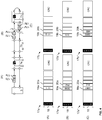
- the first data packet and the number of second data packets are of the same type. A corresponding one
- the data packet 17 shown as an example consists of a general header part - which can also be called a header -, an information part - which can also be called payload - and a checksum part - which can also be called a checksum.
- the header contains a field 18 which contains a unique bit pattern ENUM which occurs only once and which can also be referred to as a code word or identifier.
- the number and configuration of unique bit patterns or code words depend on the coding used on the local bus 6. Alternatively or additionally, however, special bit patterns or code words can also be defined in the bus protocol used. It is only important that the data bus subscribers 7a, 7b,. In the exemplary embodiment shown here, the data bus subscribers 7a, 7b, ..., 7n know that when a field 18 with a bit pattern ENUM is received, it is a data packet 17 for initialization or intermediate initialization.
- the header can also contain further information that can be used to control or check the data packet 17 and the data contained therein.
- the person skilled in the art is familiar with a large number of fields that can be contained in the header.
- the information part of the data packet 17 has several fields that can be used for initialization and intermediate initialization.
- the data packet 17 has a first counter value 23 and a second counter value 19.
- the first counter value 23 is used to count the data bus subscribers 7a, 7b,..., 7n on the local bus 6.
- the first counter value becomes 23 of each Data bus subscriber 7a, 7b, ..., 7n that is ready for communication, ie changed by each data bus subscriber 7a, 7b, ..., 7n that can process the data packet 17, for example.
- This change can consist in an incrementing or decrementing of the value of the first counter value 23.
- the data packet 17 also has a second counter value 19, which is used to assign the data packet 17 to the communication-ready data bus subscribers 7a, b,..., 7n, as follows with regard to the Figures 3 to 7 is explained in more detail.
- the data packet has a field 20 which can be used by the data bus users 7a, 7b,..., 7n in order to communicate their stored address to the local bus master 3.
- the data packet 17 also has a field 21 with which the local bus master 3 can assign a new address to the data bus users 7a, 7b, ..., 7n.
- the data packet 17 can also have a further field 22 which can carry control information for the respective data bus subscribers 7a, 7b,..., 7n.
- the data packet 17 is divided into symbols of 8 bits each.
- the data packet 17 is also received and processed in this denomination by the data bus subscribers 7a, 7b, ..., 7n. Ie first of all the local bus master 3 sends the symbol or field ENUM 18 to the first data bus participant 7a, after a predetermined time, the local bus master 3 sends another symbol of the header of the data packet 17 to the data bus participant 7a, which in turn sends the symbol or field at the same time ENUM 18 to the data bus subscriber 7b.
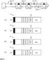
- Figure 3 shows an example of the initialization of the local bus 6.
- only data bus subscribers 7a and 7n are ready for communication.
- data bus subscriber 7b is present on local bus 6, it is not yet ready for communication, which is represented by the fact that data bus subscriber 7b only passes through the downward and upward data stream.
- the local bus master 3 sends a first data packet 17 symbol by symbol to the communication-ready data bus subscriber 7a. This is indicated by the first data packet 17 at position (A) of the local bus 6. That is to say, the data bus subscriber 7a first receives the field 18 of the first data packet 17 with the one-to-one bit pattern and is aware that an initialization is now taking place.
- the field 23 When the field 23 is then received at the data bus subscriber 7a, the latter can carry out processing with it, namely change the value of this field 23.
- the field 23 has a binary value and the data bus subscriber 7a increments the binary value.
- the value of the first counter value 23 was set to 0000 by the local bus master 3 and the data bus subscriber 7a has this value incremented by one to 0001 was sent by local bus master 3. In the exemplary embodiment shown here, this is shown below with the identification of the data packet as data packet 17 '.
- the data bus subscriber 7a itself also sends the data packet 17 'symbol-by-symbol to the next data bus subscriber 7b.
- the data bus subscriber 7b Since the data bus subscriber 7b is not yet ready for communication, it forwards the symbols of the data packet 17 'directly to the next data bus subscriber, in the exemplary embodiment shown here, to the data bus subscriber 7n. This is indicated by the data packet 17 ′ at position (B) of the local bus 6.
- the data packet 17 ' was therefore not processed by the data bus subscriber 7b that is not yet ready for communication, ie the value of the first counter value corresponds to the value to which the data bus subscriber 7a has incremented it, namely 0001.
- the data bus subscriber 7n then receives the data packet 17' and initially recognizes this Unique bit pattern 18.
- the first counter value 23 is incremented to 0010 because the data bus subscriber 7n is already ready for communication.
- the data bus subscriber 7n forwards the data packet 17 ′′ changed in this way back to the local bus master 3. This is indicated by the data packet 17 ′′ at position (C) of the local bus 6.
- the local bus master 3 can then read out the first counter value 23 from the data packet 17 ′′ and can thereby find out how many data bus users 7a, 7n that are ready for communication are present on the local bus 6. This is because only the data bus users 7a, 7n that are ready to communicate change the counter value 23, however, the data bus subscribers 7b that are not ready for communication do not change this.
- the local bus master 3 then generates data packets 17 in the number of communication-ready data bus users 7a, 7n indicated by the first counter value 23; this is shown in FIG Figure 4 shown.
- the local bus master 3 generates two second data packets 17a and 17b corresponding to the first counter value 23.
- Each data packet 17a, 17b has a second counter value 19a, 19b. With the aid of this second counter value 19a, 19b, the two data packets 17a, 17b are assigned to the communication-ready data bus users 7a and 7n.
- the local bus master 3 sets the second counter value 19a of the data packet 17a to the highest binary representation that the second counter value 19a can assume, in the exemplary embodiment shown here to 1111 17a is set to a reduced value, here to 1110.
- the data packets 17a, 17b are then sent from the local bus master 3 to the first data bus subscriber 7a. This is indicated by the data packets 17a and 17b at position (A) of the local bus 6.
- the first data bus subscriber 7a receives the two data packets 17a and 17b symbol by symbol.
- the data bus subscriber 7a increments the second counter value 19a and 19b of the two data packets 17a and 17b.
- the data bus subscriber 7a determines that there is a zero crossing, i.e. the second counter value 19a, 19b of a data packet jumps to zero when incrementing, the data bus subscriber 7a recognizes that the corresponding data packet 17a, 17b in which the second counter value 19a, 19b jumps to zero is directed to the data bus subscriber 7a.
- the data packet 17a sent first is on the data bus subscriber 7a directed.
- the second counter value 19a experiences a zero crossing when the second counter value 19a is increased by the data bus subscriber 7a.
- the data bus subscriber 7a knows that the following symbols which pass through the data bus subscriber 7a are intended for this data bus subscriber 7a.
- the second counter value 19a precedes the other fields in the information part of the data packet 17a, so that when a zero crossing of the second counter value 19a is detected, the data bus subscriber 7a can process the following symbols.
- the data bus subscriber 7a is designed to write its address in the field 20a of the data packet 17a directed to the data bus subscriber 7a.
- the address of the data bus subscriber 7a is # 42.
- the person skilled in the art is aware that the data bus subscriber 7a can also be designed to write other information into the data packet 17a and that the address information is only used here as an example.
- the data bus subscriber 7a determines the end of the data packet 17a by receiving the symbol with the one-to-one bit pattern 18b of the second data packet 17b sent.
- the data bus subscriber 7a also increases the second counter value 19b of this data packet 17b.
- the value of the second counter value 19b was adjusted by the local bus master 3 in such a way that the value of the second counter value 19b of the data packet 17b was reduced by one compared to the value of the second counter value 19a of the data packet 17a, a zero crossing is not yet recognized, but the value of the second counter value 19b of data packet 17b is only set from 1110 to 1111.
- the data bus subscriber 7a forwards the data packets 17a 'and 17b' symbol by symbol to the next data bus subscriber 7b. However, since this is still not ready for communication, the data packets 17a ', 17b' are forwarded unchanged to the next data bus subscriber 7n. This is indicated by the data packets 17a 'and 17b' at position (B) of the local bus 6.
- the data bus subscriber 7n also receives the data packets 17a 'and 17b' symbol by symbol and this data bus subscriber 7n is also adapted to increase the value of the second counter value 19a, 19b. This has the result that the value of the second counter value 19a of the data packet 17a 'is set from 0000 to 0001 and the value of the second counter value 19b of the data packet 17b' experiences a zero crossing.
- the data bus participant 7n recognizes in this case that the data packet 17b 'is directed to the data bus participant 7n and knows that the The following symbols are directed to the data bus subscriber 7n.
- the data bus subscriber 7n inserts its address into the field 20b of the data packet 17b ', the address of the data bus subscriber 7n being # 88.
- the person skilled in the art is aware that information other than the address information can also be written into the data packet 17b '.
- the data bus subscriber 7n forwards the symbols of the data packets 17a "and 17n" to the local bus master 3. This is indicated by the data packets 17a ′′ and 17b ′′ at position (C) of the local bus 6.
- the local bus master 3 receives the data packets 17a "and 17b" with the fields 20a and 20b and thus gains knowledge that the data bus subscriber 7a has the address # 42 and the data bus subscriber 7n the address # 88. If the data bus users 7a, 7n are adapted to write other information in the data packets 17a, 17b, the local bus master 3 accordingly gains knowledge of this information.
- the local bus master 3 can verify that the initialization was successful when the value of the second counter value 19b of the last data packet 17b ′′ is equal to zero, provided that no further processing of the data packets takes place in the upward direction.
- Figures 5a and 5b show the same situation as Figure 4 , namely the routing of two data packets 17a and 17b through the local bus 6, whereby each communication-ready data bus subscriber 7a, 7b, ..., 7n with a detected zero crossing of the value of the second counter value 19a, 19b its address in the following field 20a, 20b of the respective data packets 17a, 17b writes.
- the data bus subscriber 7b has become ready for communication.
- the data bus subscriber 7b does not simply pass the data packets 17a 'and 17b' through, but processes them. From the local bus master 3 to the data bus subscriber 7a, the situation corresponds to Figure 4 . This is indicated by the data packets 17a and 17b at position (A) of the local bus 6.
- the data bus subscriber 7a receives the data packets 17a, 17b, increases the values of the respective second counter values 19a, 19b and recognizes in the data packet 17a a zero crossing of the value of the second counter value 19a of this data packet 17a and writes its address # 42 in the field 20a of the data packet 17a.
- the data bus subscriber 7a also increases the value of the second Counter value 19b of the data packet 17b by a value from 1110 to 1111 and forwards the data packets 17a ', 17b' to the next data bus subscriber 7b. This is indicated by the data packets 17a 'and 17b' at position (B) of the local bus 6.
- the data bus subscriber 7b is now ready for communication and carries out the same processing operations as the data bus subscribers 7a and 7n.
- the data bus subscriber 7b increases the value of the second counter values 19a, 19b of the respective data packets 17a ', 17b' accordingly and detects a zero crossing at the value of the second counter value 19b of the data packet 17b '.
- the data bus subscriber 7b writes its address # 56 in the field 20b of the data packet 17b '.
- the data packets 17a 'and 17b' are passed from the data bus subscriber 7b to the next data bus subscriber 7n. This is indicated by the data packets 17a ′′ and 17b ′′ at position (C) of the local bus 6.
- the data bus subscriber 7n does not recognize a zero crossing in any of the data packets 17a ", 17b” because the data packet 17b "directed to this data bus subscriber 7n has already been used by the second data bus subscriber 7b to communicate its address.
- the data bus subscriber 7n increases accordingly the value of the second counter values 19a, 19b of the respective data packets 17a ", 17b” but does not communicate its address.
- the data bus subscriber 7n forwards the data packets 17a ′′′, 17b to the local bus master 3. This is done with the data packets 17a and 17b ′′′ Position (D) of the local bus 6.
- the local bus master 3 recognizes that the value of the second counter value 19b of the last data packet 17b ′′′ deviates from zero Data bus subscribers 7a, 7b, ..., 7n match.
- the local bus master 3 recognizes the difference between the value of the two iten counter value 19b of the last data packet 17b ′′′ compared to the value of the first counter value 23 used to count the communication-ready data bus subscribers 7a, 7b, ..., 7n, how many communication-ready data bus subscribers 7a, 7b, ..., 7n have been added.
- the local bus master 3 can use this information to send a corresponding number of data packets again. However, after recognizing that one or more new data bus subscribers 7b have become ready for communication, the local bus master 3 can wait for a predetermined time before another single first data packet 17 is used to count the data bus subscribers 7a, 7b, ... that are now ready for communication on the local bus 6. , 7n is sent, this is in Figure 6 shown.
- Figure 6 shows the renewed counting of the communication-ready data bus subscribers 7a, 7b, ..., 7n present on the local bus 6.
- the local bus master 3 sends a single first data packet 17 symbol by symbol to the communication-ready data bus subscriber 7a. This is indicated by the data packet 17 at position (A) of the local bus 6.
- the data bus subscriber 7a first receives the field 18 of the data packet with the one-to-one bit pattern and is aware that an initialization is now taking place.
- the field 23 is then received at the data bus subscriber 7a, the latter can carry out processing with it, namely change the value of this field 23.
- the field 23 has a binary value and the data bus subscriber 7a increments the binary value.
- the value of the first counter value 23 was set to 0000 by the local bus master 3 and the data bus subscriber 7a has this value incremented by one to 0001 Local bus master 3 was sent, this is shown in the embodiment shown here in the further with the identification of the data packet as data packet 17 '.
- the data bus subscriber 7a itself also sends the data packet 17 'symbol-by-symbol to the next data bus subscriber 7b.
- the data bus subscriber 7b receives the data packet 17 'and increments the value of the first counter value 23. That is, after passing through the data bus subscriber 7b, the data packet differs from the data packet 17' that was sent by the data bus subscriber 7a.
- this is shown further with the identification of the data packet as data packet 17 ′′.
- the data bus subscriber 7b itself also sends the data packet 17 ′′ on to the next data bus subscriber 7n symbol by symbol.
- the data bus subscriber 7n receives the data packet 17 ′′ and increments the value of the first counter value 23. That is, after passing through the data bus subscriber 7n, the data packet differs from the data packet 17 ′′ that was sent by the data bus subscriber 7b. In the exemplary embodiment shown here, this is shown below with the identification of the data packet as data packet 17 '.
- the data bus subscriber 7n itself also sends the data packet 17 ′′′ symbol by symbol to the local bus master 3.
- the local bus master 3 then knows how many communication-ready data bus subscribers 7a, 7b, ..., 7n the local bus 6 has.
- a number of second data packets 17a, 17b, 17c are then generated again by the local bus master 3.
- the values of the second counter values 19a, 19b, 19c of the respective data packets 17a, 17b, 17c are each adapted to assign the data packets 17a, 17b, 17c to the respective data bus users 7a, 7b, ..., 7n in sequence. It's in the Figures 7a and 7b shown.
- the local bus master 3 adjusts the value of the second counter value 19a, 19b, 19c of the respective data packets 17a, 17b, 17c so that they differ by one value and the first data packet 17a has the highest value of the second counter value 19a.
- the data packets 17a, 17b, 17c are sent symbol by symbol on the local bus 6. This is indicated by the data packets 17a, 17b, 17c at position (A) of the local bus 6.
- the data bus subscriber 7a receives the data packets 17a, 17b, 17c and increases the value of the second counter value 19a, 19b, 19c of the respective data packets 17a, 17b, 17c.
- the data bus subscriber 7a detects a zero crossing when the second counter value 19a is increased and detects that this data packet 17a is directed to the data bus subscriber 7a.
- the data bus subscriber 7a accordingly writes its address # 42 in the following field 20a of the data packet 17a.
- the data packets 17a ', 17b', 17c ' are forwarded from the data bus user 7a to the data bus user 7b. This is indicated by the data packets 17a ', 17b', 17c 'at position (B) of the local bus 6.
- This data bus subscriber 7b also increases the values of the second counter values 19a, 19b, 19c of the respective data packets 17a ', 17b', 17c 'and determines a zero crossing of the value of the second counter value 19b in the data packet 17b'.
- the data bus subscriber 7b recognizes that the data packet 17b 'is directed to the data bus subscriber 7b.
- the data bus subscriber 7b accordingly writes its address # 56 in the following field 20b of the data packet 17b '.
- the data packets 17a ′′, 17b ′′, 17c ′′ are forwarded from the data bus subscriber 7b to the data bus subscriber 7n.
- This data bus subscriber 7n also increases the values of the second counter values 19a, 19b, 19c of the respective data packets 17a ", 17b", 17c "and determines a zero crossing of the value of the second counter value 19c in the data packet 17c".
- the data bus subscriber 7n recognizes that the data packet 17c ′′ is sent to the data bus subscriber 7n is directed.
- the data bus subscriber 7n writes its address # 88 accordingly in the following field 20c of the data packet 17c ".
- the data packets 17a ′′′, 17b ′′′, 17c ′′′ are returned from the data bus subscriber 7n to the local bus master 3. This is done with the data packets 17a ′′′, 17b ′′′ , 17c ′′′ at position (D) of the local bus 6 indicated.
- the local bus master 3 After receiving the data packets 17a ′′′, 17b ′′′, 17c ′′′, the local bus master 3 knows the addresses of the data bus users 7a, 7b, ..., 7n, namely # 42, # 56, # 88. The local bus master 3 can also verify whether new data bus subscribers have meanwhile become ready for communication, for example by determining whether the value of the second counter value 19c of the last data packet 17c ′′′ is equal to zero or deviates. In the event that the value of the second counter value 19c of the last data packet 17c corresponds to zero, the address information in the data packets is valid. Otherwise it is counted again and the process begins again.
- the local bus master 3 can be adapted to send at least one first data packet 17 again to again to count all data bus participants 17a, 17b, 17c and to verify that the number of communication-ready data bus participants 7a, 7b, ..., 7n has not changed.
- the person skilled in the art is aware that other data can also be exchanged with the local bus master 3 in the manner shown.
- the person skilled in the art is also aware that the described methods can be used by the local bus master 3 during an initialization of the local bus 6 in order to collect information about the communication-ready data bus users 7a, 7b, ..., 7n even if the addresses of these data bus users 7a, 7b, ..., 7n are not known but the second counter value 19 can be used for the relative addressing of the data packets.
Landscapes
- Engineering & Computer Science (AREA)
- Computer Networks & Wireless Communication (AREA)
- Signal Processing (AREA)
- Small-Scale Networks (AREA)
Description
Die Erfindung betrifft im Allgemeinen die Initialisierung eines Lokalbusses, insbesondere die Informationsabfrage in einem Lokalbus mittels relativer Adressierung.The invention generally relates to the initialization of a local bus, in particular the information query in a local bus by means of relative addressing.
Bussysteme und insbesondere Lokalbussysteme sind aus heutigen Automatisierungsanlagen kaum noch wegzudenken. Automatisierungsanlagen werden insbesondere zur Steuerung von industriellen Anlagen, Gebäuden sowie von Verkehrsmitteln eingesetzt. Für die Steuerung einer Automatisierungsanlage sind zumeist mehrere Sensoren und Aktoren notwendig. Diese überwachen und steuern den von der Anlage ausgeführten Prozess. Die unterschiedlichen Sensoren und Aktoren einer Automatisierungsanlage werden dabei häufig auch als Automatisierungsgeräte bezeichnet.Bus systems and especially local bus systems have become an indispensable part of today's automation systems. Automation systems are used in particular to control industrial systems, buildings and means of transport. Several sensors and actuators are usually required to control an automation system. These monitor and control the process carried out by the system. The different sensors and actuators of an automation system are often also referred to as automation devices.
Diese Automatisierungsgeräte können entweder direkt mit einer Steuerung der Automatisierungsanlage verbunden werden, oder können zunächst mit Ein- und Ausgangsmodulen, die häufig auch als E/A-Module bezeichnet werden, verbunden werden. Diese können dann wiederum direkt mit der Steuerung verbunden werden. Die Automatisierungsgeräte können dabei entweder direkt in den E/A-Modulen integriert sein oder können mit diesen über Kabel oder kabellos verbunden sein.These automation devices can either be connected directly to a controller of the automation system, or can initially be connected to input and output modules, which are often also referred to as I / O modules. These can then in turn be connected directly to the controller. The automation devices can either be integrated directly into the I / O modules or can be connected to them via cables or wirelessly.
Die Steuerung einer Automatisierungsanlage wird in der Regel mit Hilfe einer oder mehrerer speicherprogrammierbaren Steuerungen, SPS, bewerkstelligt. Die SPSs können dabei hierarchisch oder dezentral in einer Automatisierungsanlage angeordnet sein. Dabei gibt es bei den SPS unterschiedliche Leistungsklassen, so dass diese je nach Rechen- und Speicherkapazität unterschiedliche Steuerungen und Regelungen übernehmen können. Eine SPS hat im einfachsten Fall Eingänge, Ausgänge, ein Betriebssystem (Firmware) und eine Schnittstelle, über die ein Anwenderprogramm geladen werden kann. Das Anwenderprogramm legt fest, wie die Ausgänge in Abhängigkeit von den Eingängen geschaltet werden sollen. Dabei können die Eingänge und Ausgänge mit den Automatisierungsgeräten und/oder den E/A-Modulen verbunden werden und anhand der im Anwenderprogramm hinterlegten Logik kann der Prozess, der von der Automatisierungsanlage durchgeführt wird, überwacht beziehungsweise gesteuert werden. Dabei wird die Überwachung des Prozesses durch die Sensoren bewerkstelligt und die Steuerung des Prozesses durch die Aktoren. Die Steuerung kann auch als zentrale Steuerung oder Zentraleinheit bezeichnet werden und übernimmt zumindest für ein mit der Steuerung verbundenes Automatisierungsgerät oder E/A-Modul die Steuerung.An automation system is usually controlled with the help of one or more programmable logic controllers, PLCs. The PLCs can be arranged hierarchically or decentrally in an automation system. The PLCs have different performance classes so that they can take on different controls and regulations depending on the computing and storage capacity. In the simplest case, a PLC has inputs, outputs, a Operating system (firmware) and an interface via which a user program can be loaded. The user program defines how the outputs are to be switched depending on the inputs. The inputs and outputs can be connected to the automation devices and / or the I / O modules and the process carried out by the automation system can be monitored or controlled using the logic stored in the user program. The process is monitored by the sensors and the process is controlled by the actuators. The controller can also be referred to as a central controller or central unit and takes over the control of at least one automation device or I / O module connected to the controller.
Allerdings ist das direkte Verbinden der Automatisierungsgeräte mit der zumindest einen Steuerung oder der E/A-Module mit der zumindest einen Steuerung in Form einer parallelen Verdrahtung, d.h. von jedem Automatisierungsgerät oder jedem E/A-Modul wird je eine Leitung zur übergeordneten Steuerung verlegt, sehr aufwendig. Gerade bei steigendem Automatisierungsgrad einer Automatisierungsanlage wächst der Verkabelungsaufwand bei paralleler Verdrahtung. Dies ist mit großem Aufwand bei der Projektierung, Installation, Inbetriebnahme und Wartung verbunden.However, the direct connection of the automation devices with the at least one controller or the I / O modules with the at least one controller is in the form of parallel wiring, i.e. a line is laid from each automation device or each I / O module to the higher-level controller, very expensive. When the degree of automation of an automation system increases, the cabling effort increases with parallel wiring. This is associated with great effort in the planning, installation, commissioning and maintenance.
Daher werden heutzutage in der Automatisierungstechnik zumeist Bussysteme eingesetzt, mit denen die Automatisierungsgeräte beziehungsweise die E/A-Module an die Steuerung angeschlossen werden können. Um die Anbindung der einzelnen Automatisierungsgeräte beziehungsweise der E/A-Module mit dem Bussystem noch weiter zu vereinfachen, werden heutzutage häufig einzelne Gruppen von Automatisierungsgeräten beziehungsweise E/A-Modulen mit Hilfe eines spezialisierten Lokalbusses zunächst untereinander zu einem Lokalbussystem verbunden und anschließend wird zumindest ein Teilnehmer dieses Lokalbusses mit dem Bussystem verbunden, welches mit der Steuerung verbunden ist. Dabei kann sich das Lokalbussystem von dem Bussystem unterscheiden, welches eingesetzt wird, um die Verbindung mit der Steuerung zu realisieren.This is why bus systems are mostly used in automation technology today, with which the automation devices or the I / O modules can be connected to the controller. In order to further simplify the connection of the individual automation devices or the I / O modules to the bus system, individual groups of automation devices or I / O modules are often first connected to one another using a specialized local bus to form a local bus system and then at least one Participants of this local bus are connected to the bus system that is connected to the controller. The local bus system can differ from the bus system that is used to establish the connection with the controller.
Der mit dem Bussystem der Steuerung verbundene Teilnehmer einer Gruppe von Lokalbusteilnehmern wird häufig auch als Lokalbusmaster bezeichnet. Alternativ wird auch die Bezeichnung Kopfstation des Lokalbussystems verwendet. Dieser Lokalbusmaster kann gegenüber anderen Lokalbusteilnehmer weitere Logiken, Schaltungen oder Funktionalitäten beinhalten, die zur Anbindung an das Bussystem der Steuerung notwendig sind. Auch kann der Lokalbusmaster selbst eine SPS beinhalten. Auch kann dieser Teilnehmer Logiken und Schaltungen zur Umsetzung zwischen den zwei Bussystemen aufweisen. Der Lokalbusmaster kann daher auch als Gateway oder Busumsetzer ausgebildet sein und sorgt für eine Umsetzung der im Format des einen Bussystems vorliegenden Daten in das Format des Lokalbussystems und umgekehrt. Zumeist aber nicht zwingend, ist der Lokalbusmaster auf die Anbindung des Lokalbusses an den übergeordneten Bus spezialisiert.The participant of a group of local bus participants connected to the bus system of the control is often also referred to as the local bus master. Alternatively, will also the name of the head station of the local bus system is used. Compared to other local bus participants, this local bus master can contain additional logics, circuits or functionalities that are necessary for connection to the bus system of the controller. The local bus master itself can also contain a PLC. This participant can also have logic and circuits for implementation between the two bus systems. The local bus master can therefore also be designed as a gateway or bus converter and ensures that the data present in the format of one bus system are converted into the format of the local bus system and vice versa. In most cases, but not necessarily, the local bus master specializes in connecting the local bus to the higher-level bus.
Die zum Einsatz kommenden Lokalbusse sind zumeist auf die speziellen Einsatzerfordernisse der Automatisierungsgeräte beziehungsweise E/A-Module abgestimmt oder berücksichtigen deren spezielle Hardwareausgestaltung. Dabei bilden die Gruppen an Automatisierungsgeräten beziehungsweise E/A-Modulen des Lokalbussystems zumeist eine Untergruppe der Automatisierungsanlage zur Ausführung einer speziellen Aufgabe in dem von der Automatisierungsanlage ausgeführten Prozess. Die auf den Bussen ausgetauschten Daten für den Prozess werden auch häufig als Lokalbusdaten oder Prozessdaten bezeichnet, weil diese Daten Informationen zur Regelung beziehungsweise Steuerung des von der Automatisierungsanlage ausgeführten Prozesses beinhaltet. Diese Daten können dabei unter anderem Messdaten, Steuerungsdaten, Zustandsdaten und/oder andere Informationen umfassen. Entsprechend des verwendeten Busprotokolls können diesen Daten andere Daten vorangestellt (engl. Header) oder angehängt (engl. Tail) sein. Diese anderen Daten können Informationen bezüglich der Daten beinhalten, oder Informationen bezüglich einer internen Kommunikation auf dem Lokalbus beinhalten. Hierbei ist eine Vielzahl von unterschiedlichen Informationen bekannt, die entsprechend des verwendeten Busprotokolls den Datenvorangestellt oder angefügt werden können. Die an einen Lokalbus angeschlossenen Lokalbusteilnehmer können auch als Datenbusteilnehmer bezeichnet werden, weil diese Daten auf dem Lokalbus austauschen. Ein Datenbusteilnehmer kann dabei zum Steuern oder Überwachen eines Prozesses dienen, insbesondere durch eine Ausgabe von Steuersignalen z.B. an Aktoren und/oder durch einen Empfang von Messsignalen z.B. von Sensoren. Der Datenbusteilnehmer setzt die Steuersignale und/oder Messsignale in Prozessdaten für den Lokalbus um oder umgekehrt. Die Datenbusteilnehmer können auch als Lokalbusteilnehmer bezeichnet werden.The local buses used are mostly tailored to the specific application requirements of the automation devices or I / O modules or take their special hardware design into account. The groups of automation devices or I / O modules of the local bus system mostly form a subgroup of the automation system for performing a special task in the process carried out by the automation system. The data exchanged on the buses for the process are also often referred to as local bus data or process data, because this data contains information for regulating or controlling the process carried out by the automation system. These data can include, among other things, measurement data, control data, status data and / or other information. Depending on the bus protocol used, this data can be preceded by other data ( header) or appended ( tail). These other data can contain information relating to the data or information relating to internal communication on the local bus. A large number of different pieces of information are known here, which can be placed in front of or appended to the data in accordance with the bus protocol used. The local bus users connected to a local bus can also be referred to as data bus users because they exchange data on the local bus. A data bus subscriber can serve to control or monitor a process, in particular by outputting control signals, for example to actuators, and / or by receiving measurement signals, for example from sensors. The data bus subscriber sets the control signals and / or measurement signals in process data for the local bus or vice versa. The data bus participants can also be referred to as local bus participants.
Ein Ringbus ist dabei eine spezialisierte Form des Lokalbusses, wie zum Beispiel aus
Zum Senden an spezifische Datenbusteilnehmer werden Datenpakete mit einer dem Datenbusteilnehmer entsprechenden Adresse versehen, so dass der Datenbusteilnehmer, der die entsprechende Adresse aufweist Kenntnis darüber bekommt, dass das Datenpaket an diesen Datenbusteilnehmer gerichtet ist. Im Stand der Technik werden bei Ringbussen häufig die Datenbusteilnehmer entsprechend ihrer physikalischen Reihenfolge im Ringbus adressiert, wie zum Beispiel in
Aufgabe der vorliegenden Erfindung ist es daher Verfahren und Vorrichtungen bereitzustellen, mit denen auch beim Tausch von Datenbusteilnehmern oder beim Initialisieren des Lokalbusses eine flexible Adressierung möglich ist und mit denen auch auf einfache Weise Informationen über die entsprechenden Datenbusteilnehmer gesammelt werden können.The object of the present invention is therefore to provide methods and devices with which flexible addressing is possible even when data bus users are exchanged or when the local bus is initialized, and with which information about the corresponding data bus users is also possible in a simple manner can be collected.
Diese Aufgabe wird mit den Verfahren und den Vorrichtungen der unabhängigen Ansprüche gelöst. Vorteilhafte Ausführungsformen sind in den Unteransprüchen beschrieben.This object is achieved with the method and the devices of the independent claims. Advantageous embodiments are described in the subclaims.
Das erfindungsgemäße Verfahren zur Kommunikation mit Datenbusteilnehmern verbunden mit einem Lokalbus, insbesondere einem Ringbus, mit einem Lokalbusmaster weist auf, Senden eines ersten Datenpakets von dem Lokalbusmaster an alle Datenbusteilnehmer zum Abzählen von kommunikationsbereiten Datenbusteilnehmer in einer Reihenfolge, wobei das erste Datenpaket einen ersten Zählerwert aufweist, der von jedem der kommunikationsbereiten Datenbusteilnehmer in der Reihenfolge geändert wird. Dabei kann der erste Zählerwert beispielsweise ein Binärwert sein. Mit anderen Worten, mit einem ersten einzelnen Datenpaket wird die Anzahl der bereits kommunikationsbereiten Datenbusteilnehmer bestimmt. In dieser Kommunikationsphase ist keine Adressierung der Datenbusteilnehmer nötig. Das erste Datenpaket zum Abzählen kann beispielsweise in einem Zyklusrahmen, auf den Lokalbus gesendet werden.The method according to the invention for communication with data bus users connected to a local bus, in particular a ring bus, with a local bus master comprises sending a first data packet from the local bus master to all data bus users in order to count communication-ready data bus users in a sequence, the first data packet having a first counter value, which is changed in the sequence by each of the communication-ready data bus participants. The first counter value can be a binary value, for example. In other words, the number of data bus users already ready for communication is determined with a first individual data packet. In this communication phase, the data bus participants do not need to be addressed. The first data packet for counting can for example be sent in a cycle frame on the local bus.
Ein Zyklusrahmen kann dabei beispielsweise als ein wiederkehrendes (zyklisches) vorzugsweise äquidistantes Zeitintervall, in dem Daten auf dem Lokalbus übertragbar sind, definiert werden. Der Zyklusrahmen weist beispielsweise zumindest eine Startkennung (SOC) und einen Zeitbereich zur Übertragung von Daten auf. Mehrere Startkennungen (SOC) aufeinander folgender Zyklusrahmen sind dabei vorteilhafterweise in einem zeitlich äquidistanten Abstand zueinander. Der genannte Zeitbereich ist für die Übertragung der Datenpakete vorgesehen. Die Startkennung (SOC) und die Datenpakete werden über den Lokalbus übertragen und durchlaufen alle Datenbusteilnehmer. Die Startkennung (SOC) ist separat, also als eigenständiges Symbol übertragbar oder vorteilhafterweise in einem Startdatenpaket (SOC-Paket) enthalten.A cycle frame can be defined, for example, as a recurring (cyclical), preferably equidistant, time interval in which data can be transmitted on the local bus. The cycle frame has, for example, at least one start identifier (SOC) and a time range for the transmission of data. Several start identifiers (SOC) of successive cycle frames are advantageously at an equidistant time interval from one another. The specified time range is intended for the transmission of the data packets. The start identifier (SOC) and the data packets are transmitted via the local bus and pass through all data bus participants. The start identifier (SOC) is separate, that is to say can be transmitted as an independent symbol or is advantageously contained in a start data packet (SOC packet).
Innerhalb des Zeitbereichs des Zyklusrahmens werden keine, ein oder mehrere Datenpakete übertragen. Vorteilhafterweise werden in einem Zyklusrahmen Leerlauf-Daten (Idle-Data) eingefügt, insbesondere angrenzend an zumindest ein Datenpaket. Vorteilhafterweise bewirkt die Übertragung der Datenpakete und/oder der Leerlauf-Daten ein ununterbrochenes Signal auf dem Lokalbus. Das Signal ermöglicht es den Datenbusteilnehmern, sich auf dieses zeitlich zu synchronisieren. Vorteilhafterweise weist der Zyklusrahmen zusätzlich einen Trailer auf. Der Trailer hat eine variable Länge und folgt auf den Zeitbereich zur Datenübertragung vorzugsweise bis zur folgenden Startkennung (SOC) des nächsten Zyklusrahmens. Vorteilhafterweise weist der Trailer Leerlauf-Daten auf.No, one or more data packets are transmitted within the time range of the cycle frame. Advantageously, idle data are used in a cycle frame (Idle data) inserted, in particular adjacent to at least one data packet. The transmission of the data packets and / or the idle data advantageously brings about an uninterrupted signal on the local bus. The signal enables the data bus participants to synchronize themselves with it in terms of time. The cycle frame advantageously also has a trailer. The trailer has a variable length and follows the time range for data transmission, preferably up to the following start identifier (SOC) of the next cycle frame. The trailer advantageously has idle data.
Jeder bereits kommunikationsbereite Datenbusteilnehmer kann bei Empfang des einzelnen Datenpakets, den im Datenpaket enthaltenen ersten Zählerwert ändern, beispielsweise diesen inkrementieren oder dekrementieren, bevor das Datenpaket beziehungsweise der den Zählerwert enthaltende Teil des Datenpakets an den nächsten Datenbusteilnehmer weiter gesendet wird. Noch nicht kommunikationsbereite Datenbusteilnehmer leiten das Datenpaket nur durch ohne den ersten Zählerwert zu ändern. Ein Datenbusteilnehmer kann dabei kommunikationsbereit sein, wenn dieser taktsynchronisiert ist mit dem Lokalbus und Datenpakete empfangen kann und diese weiterleiten kann und in der Lage ist, Verarbeitungen mit den Datenpaketen durchzuführen. Handelt es sich bei dem Lokalbus um einen Ringbus, so wird das Datenpaket vom letzten Datenbusteilnehmer, egal ob dieser bereits kommunikationsbereit ist oder nicht an den Lokalbusmaster zurück geleitet. Alternativ kann der Ringbus auch durch eine Brückeneinheit geschlossen werden, die die Datenpakete, die in Abwärtsrichtung empfangen werden wieder in Aufwärtsrichtung sendet. Dies geschieht entweder erneut durch alle Datenbusteilnehmer hindurch, so dass diese erneut eine Verarbeitung durchführen können, oder vorbei an allen Datenbusteilnehmern über eine Bypassverbindung. Anhand des ersten Zählerwertes weiß der Lokalbusmaster anschließend, wie viele Datenbusteilnehmer des Lokalbusses bereits kommunikationsbereit sind. Zur Informationsabfrage erzeugt der Lokalbusmaster anschließend eine Anzahl von zweiten Datenpaketen. Dabei entspricht die Anzahl der zweiten Datenpakete der Anzahl von durch den ersten Zählerwert angezeigten kommunikationsbereiten Datenbusteilnehmern. Hat der erste Zählerwert beispielsweise angezeigt, dass es N kommunikationsbereite Datenbusteilnehmer gibt, so werden auch N zweite Datenpakete erzeugt und auf dem Lokalbus gesendet, wobei N eine natürliche ganze Zahl ist. Anschließend wird die Anzahl von zweiten Datenpaketen von dem Lokalbusmaster auf den Lokalbus gesendet. Jeweils eins der erzeugten zweiten Datenpakete ist für einen kommunikationsbereiten Datenbusteilnehmer bestimmt und ist diesem basierend auf der jeweiligen relativen Position des kommunikationsbereiten Datenbusteilnehmers innerhalb der Reihenfolge zugewiesen. Mit anderen Worten, die kommunikationsbereiten Datenbusteilnehmer haben in einer bestimmten Reihenfolge den ersten Zählerwert des ersten Datenpakets geändert. Die Anzahl von zweiten Datenpaketen werden vorzugsweise in einer Reihenfolge auf den Lokalbus gesendet, die der Reihenfolge des Änderns des ersten Zählerwertes entspricht. Diese zweiten Datenpakete können dann dazu verwendet werden die jeweiligen Datenbusteilnehmer anzusprechen, ohne dass deren Adresse bekannt ist. D.h. mit Hilfe des ersten Datenpakets wird die relative Position der kommunikationsbereiten Datenbusteilnehmer im Lokalbus bestimmt und diese relative Position wird anschließend verwendet, um die kommunikationsbereiten Datenbusteilnehmer zu adressieren beziehungsweise diesen zweite Datenpakete zuzuweisen und zu senden. Durch die Verwendung der relativen Position der Datenbusteilnehmer, die nicht abhängt von der physikalischen Position des Datenbusteilnehmers, sondern von dessen Kommunikationsbereitschaft, ist eine flexible Kommunikation und Informationssammlung möglich. Jedes Datenpaket der Anzahl von zweiten Datenpaketen ist dabei genau einem Datenbusteilnehmer zugewiesen, der dieses zweite Datenpaket, zur Informationsweitergabe an den Lokalbusmaster verwendet. Der Lokalbusmaster adressiert die Datenbusteilnehmer dementsprechend in dieser Phase der Kommunikation der Reihe nach und zwar in der Reihenfolge in der die Datenbusteilnehmer den ersten Zählerwert des ersten Datenpakets geändert haben.Each data bus subscriber that is already ready for communication can change the first counter value contained in the data packet upon receipt of the individual data packet, for example increment or decrement it before the data packet or the part of the data packet containing the counter value is sent on to the next data bus subscriber. Data bus participants that are not yet ready for communication only pass the data packet through without changing the first counter value. A data bus subscriber can be ready for communication if it is clock-synchronized with the local bus and can receive data packets and forward them and is able to carry out processing with the data packets. If the local bus is a ring bus, the data packet is returned to the local bus master from the last data bus participant, regardless of whether it is already ready for communication or not. Alternatively, the ring bus can also be closed by a bridge unit that sends the data packets that are received in the downward direction back in the upward direction. This happens either again through all data bus participants so that they can carry out processing again, or past all data bus participants via a bypass connection. Using the first counter value, the local bus master then knows how many data bus users on the local bus are already ready for communication. To query information, the local bus master then generates a number of second data packets. The number of second data packets corresponds to the number of communication-ready data bus users indicated by the first counter value. If the first counter value has indicated, for example, that there are N data bus users ready for communication, then N second data packets are also generated and sent on the local bus, where N is a natural integer. Then the number of second data packets sent by the local bus master to the local bus. In each case one of the generated second data packets is intended for a communication-ready data bus subscriber and is assigned to this on the basis of the respective relative position of the communication-ready data bus subscriber within the sequence. In other words, the communication-ready data bus users have changed the first counter value of the first data packet in a specific order. The number of second data packets are preferably sent on the local bus in an order that corresponds to the order in which the first counter value was changed. These second data packets can then be used to address the respective data bus subscribers without their address being known. That is, with the aid of the first data packet, the relative position of the communication-ready data bus subscribers in the local bus is determined and this relative position is then used to address the communication-ready data bus subscribers or to assign and send second data packets to them. By using the relative position of the data bus participants, which does not depend on the physical position of the data bus participant but on its readiness for communication, flexible communication and information collection is possible. Each data packet of the number of second data packets is assigned to exactly one data bus subscriber who uses this second data packet to forward information to the local bus master. The local bus master accordingly addresses the data bus subscribers one after the other in this phase of communication, specifically in the order in which the data bus subscribers changed the first counter value of the first data packet.
Die hier beschriebenen auf dem Lokalbus übertragenen Datenpakete können auch als Telegramme bezeichnet werden. Die Datenpakete können auch als Kommunikationsdatenpakete bezeichnet werden, die insbesondere zum Programmieren und/oder zum Steuern und/oder zum Überwachen und/oder zum Identifizieren zumindest eines Datenbusteilnehmers dienen.The data packets transmitted on the local bus described here can also be referred to as telegrams. The data packets can also be referred to as communication data packets, which are used in particular for programming and / or for controlling and / or for monitoring and / or for identifying at least one data bus participant.
Die Datenbusteilnehmer dienen zum Steuern oder Überwachen eines Prozesses, insbesondere durch eine Ausgabe von Steuersignalen z.B. an Aktoren und/oder durch einen Empfang von Messsignalen z.B. von Sensoren. Der Datenbusteilnehmer setzt die Steuersignale und/oder Messsignale in Daten für den Lokalbus um oder umgekehrt.The data bus subscribers are used to control or monitor a process, in particular by outputting control signals, for example to actuators, and / or by receiving measurement signals, for example from sensors. The data bus participant sets the Control signals and / or measurement signals in data for the local bus or vice versa.
In einer bevorzugten Ausführungsform des erfindungsgemäßen Verfahrens ist das einzelne für die erste Zählung verwendete Datenpaket vom gleichen Typ, wie die Anzahl von zweiten Datenpaketen, die entsprechend der Anzahl des ersten Zählerwertes vom Lokalbusmsster erzeugt werden und auf den Lokalbus gesendet werden.In a preferred embodiment of the method according to the invention, the individual data packet used for the first count is of the same type as the number of second data packets that are generated by the local bus system and sent on the local bus according to the number of the first counter value.
In einer bevorzugten Ausführungsform des erfindungsgemäßen Verfahrens weist jedes Datenpaket der Anzahl von zweiten Datenpaketen einen zweiten Zählerwert zur Zuweisung des Datenpakets auf, wobei sich der zweite Zählerwert in jedem der zweiten Datenpakete unterscheidet also einen unterschiedlichen Startwert hat. Dieser zweite Zählerwert wird verwendet zur relativen Adressierung der Datenbusteilnehmer. Erkennt ein Datenbusteilnehmer, dass ein zweiter Zählerwert eines Datenpakets, der für die relative Adressierung verwendet wird, einem bestimmten Referenzwert entspricht, so erkennt dieser Datenbusteilnehmer, dass das diesen zweiten Zählerwert tragende Datenpaket für den Datenbusteilnehmer bestimmt ist. Bei der relativen Adressierung ändert jeder Datenbusteilnehmer den zweiten Zählerwert jedes von der Anzahl von zweiten Datenpaketen. Das Ändern kann dabei ein Inkrementieren oder Dekrementieren des zweiten Zählerwertes sein. Der Lokalbusmaster kann dabei angepasst sein, den zweiten Zählerwert entsprechend der Anzahl der gezählten Datenbusteilnehmer, also dem ersten Zählerwert derart anzupassen, dass sich jeder zweite Zählerwert unterscheidet. Außerdem wird jeder zweite Zählerwert derart angepasst, dass durch die Änderung des zweiten Zählerwertes durch die Datenbusteilnehmer, der zweite Zählerwert bei nur genau einem kommunikationsbereiten Datenbusteilnehmer einen Referenzwert erreicht. Der Referenzwert kann dabei beispielsweise in allen Datenbusteilnehmern der gleiche Referenzwert sein, so dass sich entsprechend der zweite Zählerwert von jedem Datenpaket unterscheidet. Erreicht der zweite Zählerwert eines Datenpakets den Referenzwert an einem kommunikationsbereiten Datenbusteilnehmer, so weiß dieser Datenbusteilnehmer, dass das Datenpaket für diesen Datenbusteilnehmer bestimmt ist. Hierzu kann jeder Datenbusteilnehmer dazu ausgelegt sein, einen Vergleich zwischen dem zweiten Zählerwert in jedem Datenpaket von der Anzahl von zweiten Datenpaketen und einem Referenzwert durchzuführen. Beispielsweise kann der zweite Zählerwert durch eine Binärdarstellung wiedergegeben werden. Beispielsweise kann das als erstes gesendete Datenpaket von der Anzahl von zweiten Datenpaketen einen zweiten Zählerwert aufweisen, der der höchsten Binärdarstellung des möglichen Wertebereiches für den zweiten Zählerwert entspricht. D.h. das als erstes gesendete Datenpaket von der Anzahl von zweiten Datenpaketen weist im zweiten Zählerwert nur Einsen auf. Der Wertebereich kann dabei abhängig sein von der maximalen Anzahl an Datenbusteilnehmern, die an den Lokalbus angeschlossen werden können. Inkrementiert der erste Datenbusteilnehmer den zweiten Zählerwert des als erstes gesendeten Datenpakets von der Anzahl von zweiten Datenpaketen, so erfährt dieser einen Nulldurchgang, d.h. die Binärdarstellung weist nur Nullen auf. Alternativ kann der Referenzwert auch ein Nulldurchgang von einer Anzahl von Signifikaten letzten Bits sein. Wenn der Referenzwert des ersten Datenbusteilnehmers Null ist, erkennt der erste Datenbusteilnehmer in dem hier genannten Beispiel, dass das Datenpaket an den ersten Datenbusteilnehmer gerichtet ist, d.h. diesem zugewiesen ist. Das als zweites auf den Lokalbus gesendete Datenpaket von der Anzahl von zweiten Datenpaketen kann für den zweiten Datenbusteilnehmer bestimmt sein, d.h. an diesen gerichtet sein. In diesem Datenpaket kann der Lokalbusmaster den zweiten Zählerwert auf einen Wert setzen, der durch zwei Datenbusteilnehmer inkrementiert werden kann, bevor dieser einen Nulldurchgang verzeichnet. Das als zweites gesendete Datenpaket von der Anzahl von zweiten Datenpaketen kann also vom ersten Datenbusteilnehmer inkrementiert werden und wird von diesem auf die höchste Binärdarstellung inkrementiert, d.h. auf einen Wert der nur Einsen aufweist. Da aber kein Nulldurchgang verzeichnet wurde, weiß der erste Datenbusteilnehmer, dass das Datenpaket nicht für den ersten Datenbusteilnehmer bestimmt ist und sendet es weiter auf dem Lokalbus an den nächsten kommunikationsbereiten Datenbusteilnehmer. Dieser inkrementiert noch einmal den bereits einmal inkrementierten zweiten Zählerwert. Hierbei wird ein Nulldurchgang erfahren, so dass der zweite kommunikationsbereite Datenbusteilnehmer weiß, dass dieses Datenpaket für den zweiten Datenbusteilnehmer bestimmt ist. Auf diese Weise kann der Lokalbusmaster alle Datenpakete der Anzahl von zweiten Datenpaketen über den zweiten Zählerwert und dessen Erreichen eines Referenzwertes den jeweiligen kommunikationsbereiten Datenbusteilnehmern zuweisen beziehungsweise an die jeweiligen Datenbusteilnehmer adressieren bzw. richten. Dabei ist dem Fachmann klar, dass auch wenn hier das Inkrementieren beschrieben ist und als Referenzwert ein Nulldurchgang angenommen wird, dies auch über ein Dekrementieren und einen Einsdurchgang bewerkstelligt werden kann. D.h. der zweite Zählerwert des als erstes gesendeten Datenpakets wird auf Null gesetzt. Wird dieser dekrementiert, so springt der Zählerwert auf nur Einsen. Das als zweites gesendete Datenpaket von der Anzahl von Datenpaketen enthält dann entsprechend als Startwert für den zweiten Zählerwert eine Eins etc. Des Weiteren ist dem Fachmann bewusst, dass auch andere Abzählmechanismen verwendet werden können, und der zweite Zählerwert entsprechend eingerichtet werden kann, um diesen Abzählmechanismen zu entsprechen. Der Zählerwert kann bei den Abzählmechanismen vorzugsweise eingerichtet sein nur genau einmal einen Referenzwert anzunehmen, so dass sich eine eineindeutige Zuweisung der Datenpakete ergibt. Beispielsweise kann auch erst ein Vergleich mit dem Referenzwert und anschließend das Inkrementieren /Dekrementieren stattfinden.In a preferred embodiment of the method according to the invention, each data packet of the number of second data packets has a second counter value for assigning the data packet, the second counter value differing in each of the second data packets, ie having a different start value. This second counter value is used for the relative addressing of the data bus participants. If a data bus participant recognizes that a second counter value of a data packet used for relative addressing corresponds to a specific reference value, then this data bus participant recognizes that the data packet carrying this second counter value is intended for the data bus participant. In the case of relative addressing, each data bus participant changes the second counter value of each of the number of second data packets. The change can be an incrementing or decrementing of the second counter value. The local bus master can be adapted to adapt the second counter value in accordance with the number of data bus users counted, that is to say the first counter value, in such a way that every second counter value differs. In addition, every second counter value is adapted in such a way that the change in the second counter value by the data bus subscribers causes the second counter value to reach a reference value for only one communication-ready data bus subscriber. The reference value can, for example, be the same reference value in all data bus subscribers, so that the second counter value differs accordingly from each data packet. If the second counter value of a data packet reaches the reference value on a communication-ready data bus participant, then this data bus participant knows that the data packet is intended for this data bus participant. For this purpose, each data bus subscriber can be designed to carry out a comparison between the second counter value in each data packet from the number of second data packets and a reference value. For example, the second Counter value can be represented by a binary representation. For example, the data packet sent first of the number of second data packets can have a second counter value which corresponds to the highest binary representation of the possible value range for the second counter value. In other words, the data packet sent first from the number of second data packets has only ones in the second counter value. The range of values can depend on the maximum number of data bus participants that can be connected to the local bus. If the first data bus subscriber increments the second counter value of the data packet sent first from the number of second data packets, then the latter experiences a zero crossing, ie the binary representation has only zeros. Alternatively, the reference value can also be a zero crossing of a number of significant last bits. If the reference value of the first data bus participant is zero, the first data bus participant recognizes in the example mentioned here that the data packet is directed to the first data bus participant, ie is assigned to it. The second data packet sent to the local bus from the number of second data packets can be intended for the second data bus subscriber, that is to say addressed to the latter. In this data packet, the local bus master can set the second counter value to a value that can be incremented by two data bus users before it crosses zero. The second data packet sent out of the number of second data packets can therefore be incremented by the first data bus subscriber and is incremented by the latter to the highest binary representation, ie to a value that has only ones. However, since no zero crossing was recorded, the first data bus participant knows that the data packet is not intended for the first data bus participant and sends it on on the local bus to the next communication-ready data bus participant. This once again increments the second counter value, which has already been incremented once. Here, a zero crossing is experienced, so that the second communication-ready data bus subscriber knows that this data packet is intended for the second data bus subscriber. In this way, the local bus master can assign all data packets of the number of second data packets via the second counter value and its reaching of a reference value to the respective communication-ready data bus subscribers or address or direct them to the respective data bus subscribers. It is clear to the person skilled in the art that even if the incrementing is described here and a zero crossing is assumed as the reference value, this is also the case can be accomplished via a decrement and a one pass. In other words, the second counter value of the data packet sent first is set to zero. If this is decremented, the counter value jumps to only ones. The data packet sent second from the number of data packets then contains a one etc. as the start value for the second counter value correspond to. In the case of the counting mechanisms, the counter value can preferably be set up to accept a reference value only exactly once, so that the data packets are assigned unambiguously. For example, a comparison with the reference value and then the incrementing / decrementing can also take place first.
Wenn ein Datenbusteilnehmer erkennt, dass ein Datenpaket an den Datenbusteilnehmer gerichtet ist, weil der zweite Zählerwert in diesem Datenpaket einen Referenzwert erreicht hat, der einem im Datenbusteilnehmer gespeicherten Referenzwert entspricht, so kann der Datenbusteilnehmer in dem Datenbusteilnehmer gespeicherte Informationen in ein Feld des Datenpakets schreiben, welches an den Datenbusteilnehmer gerichtet ist. Beispielsweise kann der Datenbusteilnehmer seine Adresse in das Feld schreiben. Auf diese Weise kann der Lokalbusmaster Informationen über die Datenbusteilnehmer sammeln.If a data bus participant detects that a data packet is directed to the data bus participant because the second counter value in this data packet has reached a reference value that corresponds to a reference value stored in the data bus participant, the data bus participant can write information stored in the data bus participant into a field of the data packet, which is directed to the data bus participant. For example, the data bus participant can write its address in the field. In this way, the local bus master can collect information about the data bus participants.
In einer bevorzugten Ausführungsform des erfindungsgemäßen Verfahrens weist dieses auf Vergleichen des ersten Zählerwertes und des zweiten Zählerwertes zumindest eines Datenpakets von der Anzahl von Datenpaketen an dem Lokalbusmaster, nach der Durchleitung durch den Lokalbus, also nachdem das zumindest eine Datenpaket verarbeitet wurde durch jeden kommunikationsbereiten Datenbusteilnehmer. Sind zwischen dem ersten Zählen und der Rückkehr der Datenpakete am Lokalbusmaster keine weiteren Datenbusteilnehmer kommunikationsbereit geworden, so gibt es eine definierte Beziehung zwischen dem ersten Zählerwert und dem zweiten Zählerwert. Beispielsweise ist der zweite Zählerwert des ersten Datenpakets von der Anzahl von zweiten Datenpaketen gleich dem ersten Zählerwert minus eins und der zweite Zählerwert des letzten Datenpakets von der Anzahl von zweiten Datenpaketen ist gleich dem Referenzwert, beispielsweise gleich Null. Dies ist bedingt durch die Anpassung des zweiten Zählerwertes an die Anzahl von durch den ersten Zählerwert abgezählten Datenbusteilnehmern. Der zweite Zählerwert jedes Datenpakets von der Anzahl von zweiten Datenpaketen wird dann entsprechend der Anzahl von Datenbusteilnehmern genau einmal von jedem Datenbusteilnehmer geändert, also der Anzahl angezeigt durch den ersten Zählerwert. Sind während des ersten Abzählens mit Hilfe des ersten Zählerwertes und dem Senden der Anzahl von zweiten Datenpaketen neue Datenbusteilnehmer kommunikationsbereit geworden, so kann der Lokalbusmaster keine feste Beziehung zwischen dem ersten und dem zweiten Zählerwert erkennen. In diesem Fall sendet der Lokalbusmaster erneut ein einzelnes erstes Datenpaket mit einem ersten Zählerwert an die Datenbusteilnehmer, der Lokalbusmaster zählt in diesem Fall also erneut die kommunikationsbereiten Datenbusteilnehmer ab. Anschließend kann beispielsweise der neue Zählerwert mit dem alten Zählerwert verglichen werden. Wenn diese übereinstimmen, dann kann festgestellt werden, dass es einen Fehler in der Übertragung gab, oder ein Datenbusteilnehmer obwohl dieser Kommunikationsbereitschaft signalisiert hat, durch die Verarbeitung des ersten Datenpakets mit dem ersten Zählerwert, dieser aber nicht in der Lage ist die Anzahl von zweiten Datenpaketen zu Verarbeiten. Weicht der neue erste Zählerwert ab vom alten Zählerwert, so ist zumindest ein weiterer Datenbusteilnehmer kommunikationsbereit geworden. In diesem Fall sendet der Lokalbusmaster erneut die Anzahl von zweiten Datenpaketen, wobei die Anzahl angepasst ist an den neuen ersten Zählerwert und die zweiten Zählerwerte der Anzahl von zweiten Datenpaketen sind auch angepasst an den neuen ersten Zählerwert. Dieses Verfahren wird so lange wiederholt, bis der Vergleich zeigt, dass keine weiteren Datenbusteilnehmer zwischenzeitlich kommunikationsbereit geworden sind.In a preferred embodiment of the method according to the invention, this includes comparing the first counter value and the second counter value of at least one data packet from the number of data packets on the local bus master after passing through the local bus, i.e. after the at least one data packet has been processed by each communication-ready data bus participant. If no further data bus subscribers have become ready for communication between the first counting and the return of the data packets to the local bus master, there is a defined relationship between the first counter value and the second counter value. For example, the second counter value of the first data packet from the number of second data packets is equal to the first counter value minus one and the second counter value of the last data packet from the number of second data packets is equal to the reference value, for example equal to zero. This is due to the adaptation of the second counter value to the number of data bus users counted by the first counter value. The second counter value of each data packet from the number of second data packets is then changed exactly once by each data bus subscriber in accordance with the number of data bus subscribers, that is to say the number indicated by the first counter value. If new data bus subscribers have become ready for communication during the first count with the aid of the first counter value and the sending of the number of second data packets, the local bus master cannot recognize a fixed relationship between the first and the second counter value. In this case, the local bus master again sends a single first data packet with a first counter value to the data bus subscribers, so in this case the local bus master again counts the data bus subscribers that are ready for communication. Then, for example, the new counter value can be compared with the old counter value. If these match, it can be determined that there was an error in the transmission, or that a data bus participant, although it has signaled readiness for communication, by processing the first data packet with the first counter value, but this is not able to count the number of second data packets to process. If the new first counter value deviates from the old counter value, at least one further data bus subscriber has become ready for communication. In this case, the local bus master sends the number of second data packets again, the number being adapted to the new first counter value and the second counter values of the number of second data packets also being adapted to the new first counter value. This process is repeated until the comparison shows that no further data bus subscribers have meanwhile become ready for communication.
In einer bevorzugten Ausführungsform des erfindungsgemäßen Verfahrens sendet der Lokalbusmaster in gewissen zeitlichen Abständen einzelne erste Datenpakete mit einem ersten Zählerwert aus, um die Anzahl der am Lokalbus angeschlossenen Datenbusteilnehmer zu überprüfen.In a preferred embodiment of the method according to the invention, the local bus master sends out individual first data packets with a first counter value at certain time intervals in order to check the number of data bus users connected to the local bus.
In einer bevorzugten Ausführungsform des erfindungsgemäßen Verfahrens sendet der Lokalbusmaster nach Erhalt der Anzahl von zweiten Datenpaketen erneut ein Datenpaket mit einem ersten Zählerwert, um zu überprüfen, ob in der Zwischenzeit keine weiteren Datenbusteilnehmer kommunikationsbereit geworden sind. D.h. der Lokalbusmaster verifiziert die Daten erhalten in der Anzahl von zweiten Datenpaketen.In a preferred embodiment of the method according to the invention, after receiving the number of second data packets, the local bus master again sends a data packet with a first counter value to check whether no further data bus users have become ready for communication in the meantime. Ie the Local bus master verifies the data received in the number of second data packets.
Die oben genannte Aufgabe wird auch gelöst durch einen Lokalbusmaster eines Lokalbusses, insbesondere eines Ringbusses, mit Datenbusteilnehmern. Der Lokalbusmaster weist dabei ein Mittel zum Senden eines ersten Datenpakets an alle Datenbusteilnehmer auf, wobei das erste Datenpaket verwendet wird zum Abzählen der kommunikationsbereiten Datenbusteilnehmer in einer Reihenfolge. Dabei kann das erste Datenpaket einen ersten Zählerwert aufweisen, der von jedem kommunikationsbereiten Datenbusteilnehmer in der Reihenfolge geändert wird. Der Lokalbusmaster kann nach dem Empfang des ersten Datenpakets dann anhand des ersten Zählerwertes des Datenpakets bestimmen, wie viele Datenbusteilnehmer bereits kommunikationsbereit sind. Des Weiteren weist der Lokalbusmaster ein Mittel zum Senden einer Anzahl von zweiten Datenpaketen auf, wobei deren Anzahl basiert auf dem ersten Zählerwert. Jedes der zweiten Datenpakete ist basierend auf der jeweiligen relativen Position der kommunikationsbereiten Datenbusteilnehmer in der Reihenfolge diesen zugewiesen, wobei die Zuweisung anhand eines zweiten Zählerwertes geschehen kann. Das Mittel zum Senden kann dabei eine Senderschaltung oder eine Transceiverschaltung sein. Die Schaltungen können in einem anwendungsspezifischen integrierten Schaltkreis (engl. ASIC) oder in einer Feld programmierbaren (Logik-)Gatter-Anordnung (engl. FPGA) implementiert sein.The above-mentioned object is also achieved by a local bus master of a local bus, in particular a ring bus, with data bus users. The local bus master has a means for sending a first data packet to all data bus users, the first data packet being used to count the communication-ready data bus users in a sequence. The first data packet can have a first counter value which is changed in the sequence by each communication-ready data bus subscriber. After receiving the first data packet, the local bus master can then use the first counter value of the data packet to determine how many data bus users are already ready for communication. Furthermore, the local bus master has a means for sending a number of second data packets, the number of which is based on the first counter value. Each of the second data packets is assigned to the communication-ready data bus subscribers in the sequence based on the respective relative position, it being possible for the assignment to take place on the basis of a second counter value. The means for transmitting can be a transmitter circuit or a transceiver circuit. The circuits can be implemented in an application-specific integrated circuit ( ASIC) or in a field-programmable (logic) gate arrangement ( FPGA).
Die oben genannte Aufgabe wird auch gelöst durch ein Verfahren zur Kommunikation mit einem Lokalbusmaster eines Lokalbusses, insbesondere eines Ringbusses, mit kommunikationsbereiten Datenbusteilnehmern. Das Verfahren weist auf Empfangen an einem kommunikationsbereiten Datenbusteilnehmer ein erstes Datenpaket von einem Lokalbusmaster, wobei das erste Datenpaket einen ersten Zählerwert aufweist, Ändern des ersten Zählerwertes in dem Datenpaket durch den kommunikationsbereiten Datenbusteilnehmer, Empfangen einer Anzahl von zweiten Datenpaketen, wobei jedes der zweiten Datenpakete einen zweiten Zählerwert aufweist. Des Weiteren weist das Verfahren auf Schreiben einer in dem kommunikationsbereiten Datenbusteilnehmer gespeicherten Information, beispielsweise einer Adresse, in ein Feld eines Datenpakets von der Anzahl von zweiten Datenpakete, welches dem kommunikationsbereiten Datenbusteilnehmer zugewiesen ist. Dabei kann der Datenbusteilnehmer erkennen, dass diesem ein Datenpaket aus der Anzahl von zweiten Datenpaketen zugewiesen ist, wenn der Datenbusteilnehmer den zweiten Zählerwert des Datenpakets ändert und dieser dann einen Referenzwert erreicht. Der zweite Zählerwert der Anzahl von zweiten Datenpaketen ist dabei in jedem Datenpaket unterschiedlich, so dass der Referenzwert nur genau einmal erreicht wird, wenn alle kommunikationsbereiten Datenbusteilnehmer den zweiten Zählerwert eines Datenpakets von der Anzahl von zweiten Datenpaketen ändern.The above-mentioned object is also achieved by a method for communication with a local bus master of a local bus, in particular a ring bus, with communication-ready data bus users. The method includes receiving a first data packet from a local bus master at a communication-ready data bus subscriber, the first data packet having a first counter value, changing the first counter value in the data packet by the communication-ready data bus subscriber, receiving a number of second data packets, each of the second data packets having one has second counter value. Furthermore, the method includes writing information stored in the communication-ready data bus subscriber, for example an address, into a field of a data packet from the number of second data packets that is assigned to the communication-ready data bus subscriber. The data bus subscriber can recognize that it has received a data packet from the number of second Data packets is assigned when the data bus subscriber changes the second counter value of the data packet and this then reaches a reference value. The second counter value of the number of second data packets is different in each data packet, so that the reference value is only reached exactly once if all communication-ready data bus users change the second counter value of a data packet from the number of second data packets.
Die oben genannte Aufgabe wird auch gelöst durch einen kommunikationsbereiten Datenbusteilnehmer eines Lokalbusses, insbesondere eines Ringbusses, mit einem Lokalbusmaster. Der kommunikationsbereite Datenbusteilnehmer weist auf ein Mittel zum Empfangen eines ersten Datenpakets von einem Lokalbusmaster, wobei das erste Datenpaket einen ersten Zählerwert aufweist, ein Mittel zum Ändern des ersten Zählerwertes in dem ersten Datenpaket, ein Mittel zum Empfangen einer Anzahl von zweiten Datenpaketen, und ein Mittel zum Schreiben einer in dem kommunikationsbereiten Datenbusteilnehmer gespeicherten Information, beispielsweise einer Adresse, in ein Feld eines Datenpakets von der Anzahl von zweiten Datenpaketen, welches an den kommunikationsbereiten Datenbusteilnehmer zugewiesen ist.The above-mentioned object is also achieved by a communication-ready data bus subscriber of a local bus, in particular a ring bus, with a local bus master. The communication-ready data bus subscriber has a means for receiving a first data packet from a local bus master, the first data packet having a first counter value, a means for changing the first counter value in the first data packet, a means for receiving a number of second data packets, and a means for writing information stored in the communication-ready data bus subscriber, for example an address, into a field of a data packet from the number of second data packets which is assigned to the communication-ready data bus subscriber.
Die oben genannte Aufgabe wird auch gelöst durch ein Lokalbussystem bestehend aus einem Lokalbusmaster und zumindest einem Datenbusteilnehmer.The above-mentioned object is also achieved by a local bus system consisting of a local bus master and at least one data bus participant.
Der Lokalbusmaster weist ein Mittel zum Senden eines ersten Datenpakets an alle Datenbusteilnehmer auf, wobei das erste Datenpaket verwendet wird zum Abzählen der kommunikationsbereiten Datenbusteilnehmer in einer Reihenfolge. Dabei kann das erste Datenpaket einen ersten Zählerwert aufweisen, der von jedem kommunikationsbereiten Datenbusteilnehmer in der Reihenfolge geändert wird. Der Lokalbusmaster kann des Weiteren ein Mittel zum Empfangen des ersten Datenpakets mit dem durch jeden kommunikationsbereiten Datenbusteilnehmer geänderten ersten Zählerwert aufweisen. Der Lokalbusmaster kann nach dem Empfang des ersten Datenpakets dann anhand des ersten Zählerwertes des Datenpakets bestimmen, wie viele Datenbusteilnehmer bereits kommunikationsbereit sind. Des Weiteren weist der Lokalbusmaster ein Mittel zum Senden einer Anzahl von zweiten Datenpaketen auf, wobei deren Anzahl basiert auf dem ersten Zählerwert. Jedes der zweiten Datenpakete ist basierend auf der jeweiligen relativen Position der kommunikationsbereiten Datenbusteilnehmer in der Reihenfolge diesen zugewiesen, wobei die Zuweisung anhand des zweiten Zählerwertes geschieht. Die Zuweisung kann dabei dadurch bewerkstelligt werden, dass jedem zweiten Datenpaket ein anderer Startwert für den zweiten Zählerwert gegeben wird.The local bus master has a means for sending a first data packet to all data bus users, the first data packet being used to count the communication-ready data bus users in a sequence. The first data packet can have a first counter value which is changed in the sequence by each communication-ready data bus subscriber. The local bus master can furthermore have a means for receiving the first data packet with the first counter value changed by each communication-ready data bus subscriber. After receiving the first data packet, the local bus master can then use the first counter value of the data packet to determine how many data bus users are already ready for communication. Furthermore, the local bus master has a means for sending a number of second data packets, the number of which is based on the first counter value. Each of the second data packets is assigned based on the respective relative position of the communication-ready data bus subscribers in the sequence, the assignment being made on the basis of the second counter value. The assignment can be accomplished by giving every second data packet a different start value for the second counter value.
Der kommunikationsbereite Datenbusteilnehmer weist ein Mittel zum Empfangen des einzelnen ersten Datenpakets von einem Lokalbusmaster auf, wobei das erste Datenpaket den ersten Zählerwert aufweist, ein Mittel zum Ändern des ersten Zählerwertes in dem ersten Datenpaket, ein Mittel zum Empfangen der Anzahl von zweiten Datenpaketen und ein Mittel zum Schreiben einer in dem kommunikationsbereiten Datenbusteilnehmer gespeicherten Information, beispielsweise einer Adresse, in ein Feld eines Datenpakets von der Anzahl von zweiten Datenpaketen, welches an den kommunikationsbereiten Datenbusteilnehmer zugewiesen ist.The communication-ready data bus subscriber has a means for receiving the individual first data packet from a local bus master, the first data packet having the first counter value, a means for changing the first counter value in the first data packet, a means for receiving the number of second data packets and a means for writing information stored in the communication-ready data bus subscriber, for example an address, into a field of a data packet from the number of second data packets which is assigned to the communication-ready data bus subscriber.
Der Lokalbusmaster kann ein Mittel zum Empfangen der durch die kommunikationsbereiten Datenbusteilnehmer geänderten zweiten Datenpakete aufweisen und kann die von den kommunikationsbereiten Datenbusteilnehmern in die zweiten Datenpakete geschriebenen Daten auslesen.The local bus master can have a means for receiving the second data packets changed by the communication-ready data bus subscribers and can read out the data written into the second data packets by the communication-ready data bus subscribers.
Die oben genannte Aufgabe wird auch gelöst durch ein computerlesbares Medium beinhaltend Code, der bewirkt, dass ein Computer eins der hierin beschriebenen Verfahren ausführt. Der Code kann dabei im Lokalbusmaster gespeichert sein und/oder im Datenbusteilnehmer. In einer bevorzugten Ausführungsform ist der Code gespeichert in einem Firmwarespeicher des Lokalbusmasters beziehungsweise in einem von den Datenbusteilnehmer zugreifbaren Speicher.The above object is also achieved by a computer readable medium containing code that causes a computer to carry out one of the methods described herein. The code can be stored in the local bus master and / or in the data bus participant. In a preferred embodiment, the code is stored in a firmware memory of the local bus master or in a memory accessible by the data bus subscribers.
Die Erfindung wird nachfolgend anhand von Ausführungsbeispielen mit den beigefügten Zeichnungen näher erläutert. Aus dem beschriebenen Ausführungsbeispielen ergeben sich weitere Einzelheiten, Merkmale und Vorteile des Gegenstands der Erfindung. Es zeigen:
- Fig. 1
- ein schematisches Blockdiagramm einer beispielhaften Automatisierungsanlage mit einer speicherprogrammierbaren Steuerung, einem übergeordneten Bus, und mehreren beispielhaften erfindungsgemäßen Datenbusteilnehmern;
- Fig. 2
- ein exemplarisches Datenpaket mit einem ersten und zweiten Zählerwert;
- Fig. 3
- das Senden eines einzelnen Datenpakets durch die in
Figur 1 gezeigten Datenbusteilnehmer zum Abzählen der Datenbusteilnehmer; - Fig. 4
- das Senden einer Anzahl von Datenpaketen durch die in
Figur 1 gezeigten Datenbusteilnehmer zur Informationsabfrage der Datenbusteilnehmer; - Fig. 5a/b
- das Senden einer Anzahl von Datenpaketen durch die in
Figur 1 gezeigten Datenbusteilnehmer mit einem zusätzlichen kommunikationsbereiten Datenbusteilnehmer; - Fig. 6
- das erneute Senden eines einzelnen Datenpakets durch die in
Figur 1 gezeigten Datenbusteilnehmer zum Abzählen der Datenbusteilnehmer; und - Fig. 7a/b
- das erneute Senden einer Anzahl von Datenpaketen durch die in
Figur 1 gezeigten Datenbusteilnehmer zur Informationsabfrage der Datenbusteilnehmer.
- Fig. 1
- a schematic block diagram of an exemplary automation system with a programmable logic controller, a higher-level bus, and several exemplary data bus users according to the invention;
- Fig. 2
- an exemplary data packet having first and second counter values;
- Fig. 3
- the sending of a single data packet by the in
Figure 1 data bus subscribers shown for counting the data bus subscribers; - Fig. 4
- the sending of a number of data packets by the in
Figure 1 data bus subscribers shown for querying the data bus subscribers for information; - Fig. 5a / b
- the sending of a number of data packets by the in
Figure 1 Data bus participant shown with an additional communication-ready data bus participant; - Fig. 6
- the resending of a single data packet by the in
Figure 1 data bus subscribers shown for counting the data bus subscribers; and - Fig. 7a / b
- the resending of a number of data packets by the in
Figure 1 shown data bus subscribers for information query of the data bus subscribers.
Die in
Zur Steuerung des Prozesses der Automatisierungsanlage ist die SPS 1 mit Automatisierungsgeräten verbunden. Um den Verdrahtungsaufwand gering zu halten werden für diese Verbindungen Bussysteme verwendet. In dem in
Der übergeordnete Bus 2 ist in dem hier gezeigten Ausführungsbeispiel mit dem Lokalbusmaster 3 verbunden. Hierzu weist der Lokalbusmaster 3 eine erste Schnittstelle 4 auf, die derart ausgelegt ist, dass diese mit dem übergeordneten Bus 2 verbunden werden kann. Die Schnittstelle 4 kann hierzu beispielsweise eine Aufnahme in Form einer Buchse aufweisen und der übergeordnete Bus 2 kann einen Stecker aufweisen, der von der Buchse aufgenommen werden kann. Dabei können der Stecker und die Buchse zum Beispiel ein Modularstecker und eine Modularbuchse sein, d.h. jede Ader des übergeordneten Busses 2 wird mit einer Verbindung in der Modularbuchse elektrisch oder optisch verbunden. Dem Fachmann sind aber auch andere Möglichkeiten bekannt, wie eine Schnittstelle 4 auszulegen ist, so dass der Lokalbusmaster 3 elektrisch oder optisch mit dem übergeordneten Bus 2 verbunden werden kann. Dem Fachmann sind dabei, Schraub-, Dreh-, Klick- oder Steckverbindungen bekannt, mit deren Hilfe sich eine elektrische oder optische Verbindung herstellen lassen kann. Dabei wird zumeist ein männlicher Stecker von einem weiblichen Gegenstück aufgenommen. Diese Aufnahme stellt zumeist nicht nur die elektrische oder optische Verbindung her, sondern sorgt auch dafür, dass die beiden Teile mechanisch gekoppelt werden und nur mit Aufwendung einer bestimmten Kraft wieder voneinander gelöst werden können. Es ist aber auch denkbar, dass der übergeordnete Bus 2 fest mit der Schnittstelle 4 verdrahtet ist.The higher-
Der Lokalbusmaster 3 in dem hier gezeigten Ausführungsbeispiel weist eine weitere zweite Schnittstelle auf, um den Lokalbusmaster 3 mit dem Lokalbus zu verbinden. An den Lokalbus sind Datenbusteilnehmer 7a, 7b, ..., 7n angeschlossen bzw. bilden diesen. Der Lokalbus ist vorteilhafterweise derart ausgebildet, dass ein vom Lokalbusmaster 3 gesendetes Datenpaket durch alle mit dem Lokalbus verbundenen Datenbusteilnehmer 7a, 7b, ..., 7n und an den Lokalbusmaster 3 zurück übertragen wird. Dabei empfängt ein Datenbusteilnehmer 7a, 7b, ..., 7n von seinem vorgelagerten Datenbusteilnehmer 7a, 7b, ..., 7n immer nur einen Teil des Datenpakets. Nach einer Zeitspanne in der die in diesem Teil enthaltenen Daten vom Datenbusteilnehmer 7a, 7b, ..., 7n verarbeitet werden können, wird der Teil an den nachgelagerten Datenbusteilnehmer 7a, 7b, ..., 7n weitergeleitet und gleichzeitig wird von dem vorgelagerten Datenbusteilnehmer 7a, 7b, ..., 7n ein neuer Teil des Datenpakets empfangen. Auf diese Weise passieren alle Teile des Datenpakets sequentiell alle Datenbusteilnehmer 7a, 7b, ..., 7n. Der Lokalbus ist vorteilhafterweise in einer ringförmigen Struktur ausgebildet. Derartige Lokalbusse können auch als Ringbus 6 bezeichnet werden. Der Lokalbus kann alternativ auch strangförmig oder sternförmig oder aus einer Kombination oder Mischform der zuvor genannten ausgebildet sein. Das Senden und Empfangen der Datenpakete wird dabei über die zweite Schnittstelle des Lokalbusmasters 3 bewerkstelligt. In dem hier gezeigten Ausführungsbeispiel teilt sich die zweite Schnittstelle in einen ersten Teil 5a und einen zweiten Teil 5b auf. Der erste Teil 5a der zweiten Schnittstelle stellt die Abwärtsverbindung im Ringbus 6 her und der zweite Teil 5b der zweiten Schnittstelle stellt die Aufwärtsverbindung im Ringbus 6 her.The
Der Ringbus 6, dessen Datensenderichtung mit Pfeilen in dem in
In dem hier gezeigten Ausführungsbeispiel werden die Verbindungen der Schnittstellen und der SPS 1 beziehungsweise den Datenbusteilnehmern 7a, 7b, ..., 7n mit Hilfe von Kabeln oder Leiterplatten und/oder zur direkten oder indirekten Kontaktierung mittels elektrischen Kontakten realisiert. Eine andere Alternative ist, dass die einzelnen Verbindungen kabellos hergestellt werden, und die Schnittstellen die notwendigen Umsetzungen auf die verwendeten Funkstandards bereitstellen.In the exemplary embodiment shown here, the connections between the interfaces and the PLC 1 or the
Auch wenn der Lokalbusmaster 3 und die einzelnen Datenbusteilnehmer 7a, 7b, ..., 7n in dem hier gezeigten Ausführungsbeispiel voneinander beabstandet gezeigt sind, der Lokalbusmaster 3 also dezentral angeordnet ist von den Datenbusteilnehmern 7a, 7b, ..., 7n, ist dem Fachmann bewusst, dass die Datenbusteilnehmer 7a, 7b, ..., 7n und der Lokalbusmaster 3 ― der auch einen Datenbusteilnehmer des Ringbusses 6 darstellt ― auch direkt miteinander verbunden werden können. Dabei können beispielsweise Kontakte des einen Datenbusteilnehmers in entsprechende Aufnahmen oder Aufnahmekontakte eines direkt benachbarten Datenbusteilnehmers greifen, um so eine elektrische Verbindung zwischen den Datenbusteilnehmern herzustellen, damit Daten in Abwärts- und Aufwärtsrichtung gesendet werden können. Beispielsweise können die Datenbusteilnehmer 7a, 7b, ...,7n an der dem Master abgewandten Seite Aufnahmen und an der dem Master zugewandten Seite Kontakte aufweisen. Werden die Datenbusteilnehmer 7a, 7b, ...,7n dann entsprechend aneinandergereiht, so greifen die Kontakte des einen Datenbusteilnehmers 7a, 7b, ..., 7n jeweils in die Aufnahmen des anderen Datenbusteilnehmers 7a, 7b, ..., 7n ein und es kann eine elektrische Verbindung erzeugt werden. Der Lokalbusmaster 3 weist dann entsprechend Kontakte an der Seite auf, die in die Aufnahmen des ersten Datenbusteilnehmers 7a greifen, um so zwischen den Schnittstellen 5a und 8 beziehungsweise den Schnittstellen 5b und 11 eine elektrische Verbindung zu erzeugen. Dem Fachmann sind aber auch noch andere Möglichkeiten, z.B. Druckkontakte, Messer- und Gabelkontakte bekannt, wie zwei direkt aneinander angeordnete Datenbusteilnehmer 7a, 7b, ..., 7n eine elektrische oder auch optische Verbindung mittels entsprechender Komponenten herstellen können.Even if the
Im Falle dessen, dass die Datenbusteilnehmer 7a, 7b, ..., 7n und der Lokalbusmaster 3 direkt miteinander verbunden werden sollen, können diese auch mechanische Aufnahmen oder mechanische Befestigungsmittel aufweisen, mit denen die einzelnen Datenbusteilnehmer 7a, 7b, ..., 7n und der Lokalbusmaster 3 miteinander verbunden werden können. Hierbei kann zum Beispiel ein Datenbusteilnehmer 7a, 7b, ..., 7n an einer Seite einen Vorsprung aufweisen und an der anderen Seite eine Hinterschneidung aufweisen. Werden die Datenbusteilnehmer 7a, 7b, ..., 7n dann aneinandergereiht, so greift ein Vorsprung in eine Hinterschneidung des anderen Datenbusteilnehmers 7a, 7b, ..., 7n ein, so dass eine mechanische Kopplung entsteht. Zur einfachen Aneinanderreihung der Datenbusteilnehmer 7a, 7b, ..., 7n können diese auch auf einer gemeinsamen Aufnahme, zum Beispiel einer Hutschiene angeordnet werden. Zur Befestigung auf der Hutschiene können die Datenbusteilnehmer 7a, 7b, ..., 7n entsprechende Befestigungsmittel aufweisen. Alternativ oder zusätzlich können die Datenbusteilnehmer 7a, 7b, ..., 7n auch beispielsweise lösbar verbindbare Befestigungsmittel aufweisen, mit denen die Datenbusteilnehmer 7a, 7b, ..., 7n entweder an der Hutschiene oder an einer anderen Aufnahme befestigt werden können. Dazu kann das lösbar verbindbare Befestigungsmittel austauschbar sein und ein entsprechendes Befestigungsmittel für die gewünschte Aufnahme kann mit den Datenbusteilnehmern 7a, 7b, ..., 7n verbunden werden, so dass diese an der gewünschten Aufnahme befestigt werden können.In the event that the
Des Weiteren weisen die Datenbusteilnehmer 7a, 7b, ..., 7n in dem in
Die Verarbeitungseinheit 12 kann dazu ausgelegt sein, empfangene Daten zu verarbeiten und Daten auszugeben. Empfangen werden können zu verarbeitende Daten entweder von einem vorgelagerten Datenbusteilnehmer oder von Eingängen 13 des Datenbusteilnehmers 7a, 7b, ..., 7n. Dabei können die Eingänge 13 des Datenbusteilnehmers 7a, 7b, ..., 7n mit Sensoren 15 verbunden sein, die zum Beispiel Messdaten, Zustandsdaten, etc. senden. Ausgegeben werden können verarbeitete Daten entweder an einen nachgelagerten Datenbusteilnehmer oder an Ausgängen 14 des Datenbusteilnehmers 7a, 7b, ..., 7n. Dabei können die Ausgänge 14 des Datenbusteilnehmers 7a, 7b, ..., 7n mit Aktoren 16 verbunden sein, die zum Beispiel mit Hilfe der an sie gerichteten Daten eine bestimmte Aktion durchführen. Wenn in Aufwärtsrichtung auch eine Verarbeitung der Daten stattfinden soll, so können Daten auch von einem nachgelagerten Datenbusteilnehmer 7a, 7b, ..., 7n empfangen werden und verarbeitete Daten an einen vorgelagerten Datenbusteilnehmer 7a, 7b, ..., 7n gesendet werden.The
Einfachheitshalber sind in dem hier gezeigten Ausführungsbeispiel die Datenbusteilnehmer 7a, 7b, ..., 7n nur mit einem Eingang 13 und einem Ausgang 14 gezeigt und auch nur Datenbusteilnehmer 7b ist mit Sensor 15 und Aktor 16 verbunden. Es ist dem Fachmann aber bewusst, dass die Datenbusteilnehmer 7a, 7b, ..., 7n eine Vielzahl von Ein- und Ausgängen 13 und 14 aufweisen können, und mit einer Vielzahl von unterschiedlichen Sensoren 15 und Aktoren 16 verbunden werden können. Dabei ist das die Sensoren 15 charakterisierende Merkmal, dass die Sensoren 15 Daten oder Signale aufnehmen und an den Datenbusteilnehmer 7a, 7b, ..., 7n senden, wohingegen Aktoren 16 Daten oder Signale von den Datenbusteilnehmern 7a, 7b, ..., 7n empfangen und basierend auf diesen Daten oder Signalen eine Aktion ausführen.For the sake of simplicity, the
Alternativ können die Schnittstellen 8, 9, 10 und 11 in einer Moduleinheit integriert sein und die Datenbusteilnehmer 7a, 7b, ..., 7n auf diese Moduleinheit aufgesteckt werden können. Die Moduleinheiten können auch als Basiselemente des Ringbusses 6 bezeichnet werden. Die Ringbusinfrastruktur wird dabei durch die Moduleinheiten aufgebaut und die Datenbusteilnehmer 7a, 7b, ..., 7n sind auswechselbar, so dass der Ringbus 6 mit beliebigen Datenbusteilnehmern 7a, 7b, ..., 7n aufgebaut werden kann. Mit Hilfe der Moduleinheiten ist auch sichergestellt, dass auch wenn ein Datenbusteilnehmer 7a, 7b, ..., 7n entfernt wird, die Kommunikation zwischen den restlichen Datenbusteilnehmern 7a, 7b, ..., 7n nicht unterbrochen wird, weil die Kommunikation über die noch vorhandenen Moduleinheiten geschieht.Alternatively, the
Die in diesem Ausführungsbeispiel gezeigten Datenbusteilnehmer 7a, 7b, ..., 7n werden auf Grund ihrer Ein- und Ausgänge 13, 14, die mit Sensoren 15 beziehungsweise Aktoren 16 verbunden werden können, auch häufig als E/A-Module bezeichnet. Auch wenn die Datenbusteilnehmer 7a, 7b, ..., 7n in dem hier gezeigten Ausführungsbeispiel als räumlich getrennt von den Sensoren 15 beziehungsweise Aktoren 16 dargestellt sind, so können die Sensoren 15 beziehungsweise Aktoren 16 auch in dem E/A-Modul integriert sein.The
Der in dem hier gezeigten Ausführungsbeispiel gezeigte Ringbus 6 basiert auf einer Zyklusrahmenkommunikation.The
Jedes Datenpaket wird von dem Lokalbusmaster 3 in Abwärtsrichtung an den ersten Datenbusteilnehmer 7a des Ringbusses 6 gesendet. Dieser empfängt einen ersten Teil des Datenpakets über die Schnittstelle 8. Ein derartiger Teil des Datenpakets wird im Folgenden auch als Stück oder Einheit bezeichnet. Der Datenbusteilnehmer 7a führt dann eine Verarbeitung des Teils aus, und leitet den Teil dann an den nächsten Datenbusteilnehmer 7b über Schnittstelle 9 weiter, vorzugsweise gleichzeitig empfängt der erste Datenbusteilnehmer 7a einen zweiten Teil des Datenpakets usw. Die Größe der Teile des Datenpakets, also die Stückelung des Datenpakets, hängt dabei von der Aufnahmekapazität der Datenbusteilnehmer 7a, 7b, ..., 7n ab, beispielsweise können zur Verarbeitung gleichzeitig eine feste Anzahl von Bits, beispielsweise 8 Bits des Datenpakets am Datenbusteilnehmer 7a, 7b, ..., 7n vorliegen.Each data packet is sent from the
Das Datenpaket durchläuft dementsprechend einheitenweise, stückchenweise, oder Teile weise, zum Beispiel in Teilen oder Symbolen von 8 Bits, die Datenbusteilnehmer 7a, 7b, ..., 7n. Der Teil des Datenpakets, welches vom letzten Datenbusteilnehmer, in dem hier gezeigten Ausführungsbeispiel Datenbusteilnehmer 7n, verarbeitet worden ist, durchläuft dann in Aufwärtsrichtung den Ringbus 6, so dass die Teile ausgehend von dem letzten Datenbusteilnehmer 7n wieder in Richtung Lokalbusmaster 3 durch alle Datenbusteilnehmer 7a, 7b, ..., 7n aufwärts gesendet werden. Hierzu weist der letzte Datenbusteilnehmer 7n entweder eine schaltbare Brücke auf, die die Schnittstelle 9 mit der Schnittstelle 10 verbindet oder an den letzten Datenbusteilnehmer 7n wird eine schaltbare Brücke ― hier nicht gezeigt ― angeschlossen, die die Funktion übernimmt die Teile des Datenpakets von der Schnittstelle 9 auf die Schnittstelle 10 zu leiten. Alternativ kann die Schnittstelle 10 des Datenbusteilnehmers 7n auch mit Hilfe einer Bypassleitung ― hier nicht gezeigt ― direkt mit der Schnittstelle 5b des Lokalbusmasters 3 verbunden werden.The data packet accordingly passes through the
In der Aufwärtsrichtung können die Einheiten des Datenpakets beziehungsweise der Datenpakete, wie in dem hier gezeigten Ausführungsbeispiel durch die einzelnen Datenbusteilnehmer 7a, 7b, ..., 7n zurück an den Lokalbusmaster 3 geschleift werden, ohne dass eine weitere Verarbeitung stattfindet. Es ist aber auch denkbar, dass in der Aufwärtsrichtung erneut eine Verarbeitung der Einheiten des Datenpakets stattfindet, so dass das Datenpaket zweimal verarbeitet werden kann, einmal auf der Abwärtsrichtung zum letzten Datenbusteilnehmer 7n und einmal in Aufwärtsrichtung zum Lokalbusmaster 3. Beispielsweise kann in Aufwärtsrichtung eine Verarbeitung durch Signalauffrischung und/oder Phasenschiebung erfolgen.In the upward direction, the units of the data packet or the data packets can be looped back to the
Bevor jedoch Datenpakete auf dem Lokalbus 6 gesendet werden können die Prozessdaten tragen, muss der Lokalbus 6 initialisiert werden.. D.h. der Lokalbusmaster 3 muss Kenntnis darüber erlangen, welche Datenbusteilnehmer 7a, 7b, ..., 7n vorhanden sind und von diesen Informationen abfragen können. Wenn der Lokalbus 6 dazu ausgelegt ist, dass die Datenbusteilnehmer 7a, 7b, ..., 7n auch während des Betriebes gewechselt werden können, was als Hot-Swap bezeichnet wird, so muss der Lokalbusmaster 3 auch in der Lage sein während des Betriebes die neuen Datenbusteilnehmer zu erkennen und von diesen Informationen abzufragen.However, before data packets can be sent on the
Erfindungsgemäß verwendet der Lokalbusmaster 3 für diese anfängliche Initialisierung oder für die Zwischeninitialisierung ein erstes Datenpaket und eine Anzahl von zweiten Datenpaketen. Das erste Datenpalet wird nicht adressiert auf den Lokalbus 6 gesendet und durchläuft alle Datenbusteilnehmer 7a, 7b, ..., 7n. Die Anzahl von zweiten Datenpaketen wird dann anschließend auf dem Lokalbus 6 gesendet und durchläuft ebenfalls alle Datenbusteilnehmer 7a, 7b, ..., 7n Das erste Datenpaket und die Anzahl von zweiten Datenpaketen sind dabei vom gleichen Typ. Ein entsprechendesAccording to the invention, the
Datenpaket ist exemplarisch in
Das in
Der Kopfteil beinhaltet ein Feld 18, welches ein eindeutiges nur einmal auftretendes Bitmuster ENUM enthält, welches auch als Codewort oder Kennung bezeichnet werden kann. Die Anzahl und die Ausgestaltung von eindeutigen Bitmustern beziehungsweise Codewörtern hängen ab von der auf dem Lokalbus 6 verwendeten Kodierung. Alternativ oder zusätzlich können aber auch spezielle Bitmuster oder Codewörter in dem verwendeten Busprotokoll definiert werden. Es ist dabei nur von Bedeutung, dass die Datenbusteilnehmer 7a, 7b, ..., 7n eineindeutig aus dem Bitmuster beziehungsweise Codewort des Feldes 18 erkennen können, um welche Art von Datenpaket 17 es sich handelt. In dem hier gezeigten Ausführungsbeispiel haben die Datenbusteilnehmer 7a, 7b, ..., 7n Kenntnis darüber, dass wenn ein Feld 18 mit einem Bitmuster ENUM empfangen wird, es sich um ein Datenpaket 17 zur Initialisierung oder Zwischeninitialisierung handelt.The header contains a
Der Kopfteil kann auch noch weitere Informationen beinhalten, die zur Steuerung oder Überprüfung des Datenpakets 17 und der darin enthaltenen Daten verwendet werden können. Dem Fachmann sind dabei eine Vielzahl von Feldern bekannt, die im Kopfteil enthalten sein können.The header can also contain further information that can be used to control or check the
Der Informationsteil des Datenpakets 17 weist mehrere Felder auf, die zur Initialisierung sowie Zwischeninitialisierung verwendet werden können. Das Datenpaket 17 weist dabei einen ersten Zählerwert 23 und einen zweiten Zählerwert 19 auf. Der erste Zählerwert 23 wird dabei verwendet, um die Datenbusteilnehmer 7a, 7b, ..., 7n auf dem Lokalbus 6 abzuzählen. Dabei wird der erste Zählerwert 23 von jedem Datenbusteilnehmer 7a, 7b, ..., 7n der kommunikationsbereit ist, d.h. von jedem Datenbusteilnehmer 7a, 7b, ..., 7n, der das Datenpaket 17 beispielsweise verarbeiten kann, geändert. Dieses Ändern kann in einem inkrementieren oder dekrementieren des Wertes des ersten Zählerwertes 23 bestehen. Wenn das Datenpaket 17 den Lokalbus 6 durchlaufen hat, also wieder am Lokalbusmaster 3 angekommen ist, hat dieser Kenntnis darüber, wie viele kommunikationsbereite Datenbusteilnehmer 7a, 7b, ..., 7n am Lokalbus 6 angeschlossen sind. Des Weiteren weist das Datenpaket 17 auch einen zweiten Zählerwert 19 auf, der zur Zuweisung des Datenpakets 17 an die kommunikationsbereiten Datenbusteilnehmer 7a, b, ..., 7n dient, wie im Folgenden in Hinblick auf die
Des Weiteren weist das Datenpaket ein Feld 20 auf, welches von den Datenbusteilnehmern 7a, 7b, ..., 7n verwendet werden kann, um ihre gespeicherte Adresse an den Lokalbusmaster 3 zu kommunizieren. Auch weist das Datenpaket 17 ein Feld 21 auf mit der der Lokalbusmaster 3 den Datenbusteilnehmern 7a, 7b, ..., 7n eine neue Adresse zuweisen kann. Des Weiteren kann das Datenpaket 17 auch noch ein weiteres Feld 22 aufweisen, welches Steuerinformation für die jeweiligen Datenbusteilnehmer 7a, 7b, ..., 7n tragen kann. Es ist dem Fachmann bewusst, dass auch wenn hier eine spezielle Reihenfolge und Anzahl der Felder 19 bis 23 vorgegeben ist, von dieser Anordnung und Anzahl der Felder abgewichen werden kann, ohne vom Gegenstand der Erfindung abzuweichen. Des Weiteren ist dem Fachmann bewusst, dass auch wenn hier nur exemplarisch die Abfrage der Adressinformation gezeigt ist, auch andere Informationen der Datenbusteilnehmer 7a, 7b, ..., 7n abgefragt werden können und dass hierzu entsprechende Felder im Datenpaket 17 enthalten sein können.Furthermore, the data packet has a
In dem hier gezeigten Ausführungsbeispiel ist das Datenpaket 17 in Symbole von jeweils 8 Bit eingeteilt. Das Datenpaket 17 wird auch in dieser Stückelung von den Datenbusteilnehmer 7a, 7b, ..., 7n empfangen und verarbeitet. D.h. als erstes sendet der Lokalbusmaster 3 das Symbol beziehungsweise Feld ENUM 18 an den ersten Datenbusteilnehmer 7a, nach einer vorher bestimmten Zeit, sendet der Lokalbusmaster 3 ein weiteres Symbol des Kopfteiles des Datenpakets 17 an den Datenbusteilnehmer 7a, dieser wiederum sendet gleichzeitig das Symbol beziehungsweise Feld ENUM 18 an den Datenbusteilnehmer 7b. In dieser Weise durchlaufen alle Teile des Datenpakets 17 die jeweiligen Datenbusteilnehmer 7a, 7b, ..., 7n, wobei zu jeder gegebenen Zeit jeder Datenbusteilnehmer 7a, 7b, ..., 7n immer nur ein Stück beziehungsweise Teil des Datenpakets 17 vorhält und damit verarbeiten kann.In the exemplary embodiment shown here, the
Anschließend erzeugt der Lokalbusmaster 3 Datenpakete 17 aber in der Anzahl der durch den ersten Zählerwert 23 angezeigten kommunikationsbereiten Datenbusteilnehmer 7a, 7n, dies ist in
In dem hier gezeigten Ausführungsbeispiel ist das zuerst gesendete Datenpaket 17a an den Datenbusteilnehmer 7a gerichtet. An diesem Datenbusteilnehmer 7a erfährt der zweite Zählerwert 19a einen Nulldurchgang, wenn der zweite Zählerwert 19a durch den Datenbusteilnehmer 7a erhöht wird. Der Datenbusteilnehmer 7a weiß in diesem Fall, dass die folgenden Symbole, die den Datenbusteilnehmer 7a durchlaufen für diesen Datenbusteilnehmer 7a bestimmt sind. Aus diesem Grund ist in diesem Ausführungsbeispiel der zweite Zählerwert 19a den weiteren Feldern im Informationsteil des Datenpakets 17a vorangestellt, so dass beim Erkennen eines Nulldurchgangs des zweiten Zählerwertes 19a der Datenbusteilnehmer 7a die folgenden Symbole verarbeiten kann. In dem hier gezeigten Ausführungsbeispiel ist der Datenbusteilnehmer 7a dazu ausgelegt, seine Adresse in das Feld 20a des an den Datenbusteilnehmer 7a gerichteten Datenpakets 17a zu schreiben. In dem hier gezeigten Ausführungsbeispiel ist die Adresse des Datenbusteilnehmers 7a #42. Dem Fachmann ist bewusst, dass der Datenbusteilnehmer 7a auch ausgelegt sein kann andere Informationen in das Datenpaket 17a zu schreiben und die Adressinformation hier nur beispielhaft verwendet wird. Das Ende des Datenpakets 17a stellt der Datenbusteilnehmer 7a fest durch den Empfang des Symbols mit dem eineindeutigen Bitmuster 18b des als zweites gesendeten Datenpakets 17b. Der Datenbusteilnehmer 7a erhöht auch den zweiten Zählerwert 19b dieses Datenpakets 17b. Da der Wert des zweiten Zählerwertes 19b durch den Lokalbusmaster 3 aber derart angepasst wurde, dass der Wert des zweiten Zählerwertes 19b des Datenpakets 17b um eins erniedrigt war gegenüber dem Wert des zweiten Zählerwertes 19a des Datenpakets 17a wird noch kein Nulldurchgang erkannt, sondern der Wert des zweiten Zählerwertes 19b des Datenpakets 17b wird nur von 1110 auf 1111 gesetzt. Der Datenbusteilnehmer 7a sendet die Datenpakete 17a' und 17b' symbolweise an den nächsten Datenbusteilnehmer 7b weiter. Da dieser aber noch immer nicht kommunikationsbereit ist, werden die Datenpakete 17a', 17b' unverändert an den nächsten Datenbusteilnehmer 7n weitergeleitet. Dies ist mit den Datenpaketen 17a' und 17b' an Position (B) des Lokalbusses 6 angedeutet. Der Datenbusteilnehmer 7n empfängt ebenfalls die Datenpakete 17a' und 17b' symbolweise und auch dieser Datenbusteilnehmer 7n ist angepasst den Wert des zweiten Zählerwertes 19a, 19b zu erhöhen. Dies führt dazu, dass der Wert des zweiten Zählerwertes 19a des Datenpakets 17a' von 0000 auf 0001 gesetzt wird und der Wert des zweiten Zählerwertes 19b des Datenpakets 17b' einen Nulldurchgang erfährt. Der Datenbusteilnehmer 7n erkennt in diesem Fall, dass das Datenpaket 17b' an den Datenbusteilnehmer 7n gerichtet ist und weiß, dass die folgenden Symbole an den Datenbusteilnehmer 7n gerichtet sind. Entsprechend des Datenbusteilnehmers 7a fügt der Datenbusteilnehmer 7n seine Adresse in das Feld 20b des Datenpakets 17b' ein, wobei die Adresse des Datenbusteilnehmers 7n #88 ist. Auch hier ist dem Fachmann bewusst, dass auch andere Informationen als die Adressinformation in das Datenpaket 17b' geschrieben werden kann. Der Datenbusteilnehmer 7n leitet die Symbole der Datenpakete 17a" und 17n" an den Lokalbusmaster 3 weiter. Dies ist mit den Datenpaketen 17a" und 17b" an Position (C) des Lokalbusses 6 angedeutet. Der Lokalbumaster 3 empfängt die Datenpakete 17a" und 17b" mit den Feldern 20a und 20b und erlangt so Kenntnis darüber, dass der Datenbusteilnehmer 7a die Adresse #42 aufweist und der Datenbusteilnehmer 7n die Adresse #88. Sind die Datenbusteilnehmer 7a, 7n angepasst andere Informationen in die Datenpakete 17a, 17b zu schreiben, so erlangt der Lokalbusmaster 3 entsprechend Kenntnis über diese Informationen. Der Lokalbusmaster 3 kann dabei verifizieren, dass das Initialisieren erfolgreich war, wenn der Wert des zweiten Zählerwertes 19b des letzten Datenpakets 17b" gleich Null ist, vorausgesetzt es findet keine weitere Verarbeitung der Datenpakete auf der Aufwärtsrichtung statt.In the exemplary embodiment shown here, the
Anschließend werden erneut eine Anzahl von zweiten Datenpaketen 17a, 17b, 17c vom Lokalbusmaster 3 erzeugt. Die Werte der zweiten Zählerwerte 19a, 19b, 19c der jeweiligen Datenpakete 17a, 17b, 17c sind jeweils angepasst, die Datenpakete 17a, 17b, 17c den jeweiligen Datenbusteilnehmern 7a, 7b, ..., 7n der Reihe nach zuzuweisen. Die ist in den
Der Lokalbusmaster 3 passt den Wert des zweiten Zählerwertes 19a, 19b, 19c der jeweiligen Datenpakte 17a, 17b, 17c so an, dass diese sich jeweils um einen Wert unterscheiden und das erste Datenpaket 17a den höchsten Wert des zweiten Zählerwertes 19a aufweist. Die Datenpakete 17a, 17b, 17c werden symbolweise auf den Lokalbus 6 gesendet. Dies ist mit den Datenpaketen 17a, 17b, 17c an Position (A) des Lokalbusses 6 angedeutet. Der Datenbusteilnehmer 7a empfängt die Datenpakete 17a, 17b, 17c und erhöht jeweils den Wert des zweiten Zählerwertes 19a, 19b, 19c der jeweiligen Datenpakete 17a, 17b, 17c. Bei dem Datenpaket 17a erkennt der Datenbusteilnehmer 7a beim Erhöhen des zweiten Zählerwertes 19a einen Nulldurchgang und erkennt, dass dieses Datenpaket 17a an den Datenbusteilnehmer 7a gerichtet ist. Der Datenbusteilnehmer 7a schreibt entsprechend seine Adresse #42 in das folgende Feld 20a des Datenpakets 17a. Die Datenpakete 17a', 17b', 17c' werden von dem Datenbusteilnehmer 7a an den Datenbusteilnehmer 7b weitergeleitet. Dies ist mit den Datenpaketen 17a', 17b', 17c' an Position (B) des Lokalbusses 6 angedeutet. Auch dieser Datenbusteilnehmer 7b erhöht die Werte der zweiten Zählerwerte 19a, 19b, 19c der jeweiligen Datenpakete 17a', 17b', 17c' und stellt beim Datenpaket 17b' einen Nulldurchgang des Wertes des zweiten Zählerwertes 19b fest. Hierdurch erkennt der Datenbusteilnehmer 7b, dass das Datenpaket 17b' an den Datenbusteilnehmer 7b gerichtet ist. Der Datenbusteilnehmer 7b schreibt entsprechend seine Adresse #56 in das folgende Feld 20b des Datenpakets 17b'. Die Datenpakete 17a", 17b", 17c" werden von dem Datenbusteilnehmer 7b an den Datenbusteilnehmer 7n weitergeleitet. Dies ist mit den Datenpaketen 17a", 17b", 17c" an Position (C) des Lokalbusses 6 angedeutet. Auch dieser Datenbusteilnehmer 7n erhöht die Werte der zweiten Zählerwerte 19a, 19b, 19c der jeweiligen Datenpakete 17a", 17b", 17c" und stellt beim Datenpaket 17c" einen Nulldurchgang des Wertes des zweiten Zählerwertes 19c fest. Hierdurch erkennt der Datenbusteilnehmer 7n, dass das Datenpaket 17c" an den Datenbusteilnehmer 7n gerichtet ist. Der Datenbusteilnehmer 7n schreibt entsprechend seine Adresse #88 in das folgende Feld 20c des Datenpakets 17c". Die Datenpakete 17a‴, 17b‴, 17c‴ werden von dem Datenbusteilnehmer 7n an den Lokalbusmaster 3 zurückgeleitet. Dies ist mit den Datenpaketen 17a‴, 17b‴, 17c‴ an Position (D) des Lokalbusses 6 angedeutet.The
Nach Erhalt der Datenpakete 17a‴, 17b‴, 17c‴ kennt der Lokalbusmaster 3 die Adressen der Datenbusteilnehmer 7a, 7b, ..., 7n, nämlich #42, #56, #88. Der Lokalbusmaster 3 kann auch verifizieren, ob zwischenzeitlich neue Datenbusteilnehmer kommunikationsbereit geworden sind, beispielsweise durch das Bestimmen, ob der Wert des zweiten Zählerwertes 19c des letzten Datenpakets 17c‴ gleich Null ist oder abweicht. Im Falle dessen, dass der Wert des zweiten Zählerwertes 19c des letzten Datenpakets 17c‴ Null entspricht, sind die Adressinformation in den Datenpaketen valide. Ansonsten wird erneut abgezählt und das Verfahren beginnt von neuem.After receiving the
Nach Verifizierung der Adressinformationen in den Datenpaketen 17a‴, 17b‴, 17c‴, durch Bestimmen ob der Wert des zweiten Zählerwertes 19c des letzten Datenpakets 17c‴ gleich Null ist, kann der Lokalbusmaster 3 angepasst sein erneut zumindest ein erstes Datenpaket 17 zu senden, um erneut alle Datenbusteilnehmer 17a, 17b, 17c abzuzählen und zu verifizieren, dass sich die Anzahl an kommunikationsbereiten Datenbusteilnehmern 7a, 7b, ..., 7n nicht geändert hat.After verification of the address information in the
Auch wenn hier nur der Austausch von Adressinformationen beschrieben ist, ist dem Fachmann bewusst, dass auch andere Daten auf die aufgezeigte Weise mit dem Lokalbusmaster 3 ausgetauscht werden können. Dem Fachmann ist auch bewusst, dass die beschriebenen Verfahren vom Lokalbusmaster 3 während einer Initialisierung des Lokalbusses 6 verwendet werden können, um Informationen über die kommunikationsbereiten Datenbusteilnehmer 7a, 7b, ..., 7n zu sammeln auch wenn die Adressen dieser Datenbusteilnehmer 7a, 7b, ..., 7n nicht bekannt sind aber der zweite Zählerwert 19 zur relativen Adressierung der Datenpakete verwendet werden kann.Even if only the exchange of address information is described here, the person skilled in the art is aware that other data can also be exchanged with the
- 11
- speicherprogrammierbare Steuerung (SPS)programmable logic controller (PLC)
- 22
- übergeordneter Bushigher-level bus
- 33
- LokalbusmasterLocal bus master
- 44th
- erste Schnittstellefirst interface
- 5a,b5a, b
- zweite Schnittstellesecond interface
- 66th
- RingbusRing bus
- 7a, b, n7a, b, n
- DatenbusteilnehmerData bus participants
- 88th
- erste Abwärtsdatenschnittstellefirst downward data interface
- 99
- zweite Abwärtsdatenschnittstellesecond downward data interface
- 1010
- erste Aufwärtsdatenschnittstellefirst upward data interface
- 1111th
- zweite Aufwärtsdatenschnittstellesecond upward data interface
- 1212th
- VerarbeitungseinheitProcessing unit
- 12'12 '
- SpeicherStorage
- 13,1413.14
- Ein-/AusgängeInputs / outputs
- 1515th
- Sensorsensor
- 1616
- AktorActuator
- 1717th
- erstes / zweites Datenpaketfirst / second data packet
- 17a, b, c17a, b, c
- Anzahl an zweiten DatenpaketenNumber of second data packets
- 1818th
- BitmusterBit pattern
- 1919th
- zweiter Zählerwertsecond counter value
- 2020th
- Feld zum Speichern der Adresse eines DatenbusteilnehmersField for storing the address of a data bus participant
- 2121
- Feld zum Zuweisen einer Adresse an einen DatenbusteilnehmerField for assigning an address to a data bus participant
- 2222nd
- SteuerinformationTax information
- 2323
- erster Zählerwertfirst counter value
Claims (15)
- A method for communication with data bus subscribers (7a, 7b, ..., 7n) connected to a local bus (6), in particular a ring bus, with a local bus master (3), the method comprising:sending a first data packet (17) from the local bus master (3) to all data bus subscribers (7a, 7b, ..., 7n) for counting communication-ready data bus subscribers (7a, 7b, ..., 7n) in an order, the first data packet (17) having a first counter value (23) that each of the communication-ready data bus subscribers (7a, 7b, ..., 7n) in the order changes; andsending a plurality of second data packets (17a, 17b, 17c) from the local bus master (3) to all data bus subscribers (7a, 7b, ..., 7n), wherein the plurality of the second data packets (17a, 17b, 17c) is based on the first counter value (23) and wherein each of the second data packets (17a, 17b, 17c) is assigned to one of the communication-ready data bus subscribers (7a, 7b, ..., ..., 7n) based on the respective relative position of the communication-ready data bus subscribers (7a, 7b, ..., 7n) within the order, and wherein the first data packet (17) and the plurality of second data packets (17a, 17b, 17c) are of the same type.
- The method according to claim 1, wherein each of the second data packets (17a, 17b, 17c) has a second counter value (19) for assignation, wherein each of said communication-ready data bus subscribers (7a, 7b, ..., 7n) in order changes the second counter value (19); and
wherein starting values of the second counter value (19) differ in particular for each of the second data packets (17a, 17b, 17c). - The method according to any of the preceding claims, further comprising:
processing every second data packet (17a, 17b, 17c) by each of the communication-ready data bus subscribers (7a, 7b, ..., 7n), wherein the second data packets (17a, 17b, 17c) are processed in succession. - The method according to claim 3, wherein the processing further comprises:
changing the second counter value (19) in each of the second data packets (17a, 17b, 17c) by each of the communication-ready data bus subscribers (7a, 7b, ..., 7n). - The method of claim 4, further comprising:
comparing the second counter value (19) in each of the second data packets (17a, 17b, 17c) with a reference value by each of the communication-ready data bus subscribers (7a, 7b, ..., 7n). - The method according to claim 5, further comprising:
writing information stored in a data bus subscriber (7a, 7b, ..., 7n) into a field (20) of one of the second data packets (17a, 17b, 17c) if a current second counter value (19) of the current second data packet (17a, 17b, 17c) corresponds to the reference value. - The method according to any of the preceding claims, wherein the first counter value (23) and/or the second counter value (19) is a binary value.
- The method according to any of the preceding claims, further comprising:
comparing the first counter value (23) and/or the second counter value (19) of at least one of the second data packets (17a, 17b, 17c) with an expected value after the at least one of the second data packets (17a, 17b, 17c) has been processed by each of the communication-ready data bus subscribers (7a, 7b, ..., 7n). - The method according to claim 8, wherein the expected value is based on the first counter value (23) of the first data packet (17) after the first data packet (17) has been processed by each of the communication-ready data bus subscribers (7a, 7b, ..., 7n).
- The method according to any of claims 8 or 9, further comprising:
resending a first data packet (17) to all of the data bus subscribers (7a, 7b, ..., 7n) if the comparison shows a deviation. - The method according to claim 10, further comprising:
resending a plurality of second data packets (17a, 17b, 17c), wherein the number thereof is based on the first counter value (23) of the resent first data packet (17) after the resent first data packet (17) has been processed by each of the communication-ready data bus subscribers (7a, 7b, ..., 7n). - A local bus master (3) of a local bus (6), in particular a ring bus, with data bus subscribers (7a, 7b, ..., 7n), the local bus master (3) comprising:means for sending a first data packet (17) to all data bus subscribers (7a, 7b, ..., 7n) for counting communication-ready data bus subscribers (7a, 7b, ..., 7n) in an order, wherein the first data packet (17) comprises a first counter value (23), for a change of this first counter value (23) by each communication-ready data bus subscriber (7a, 7b, ..., 7n) in the order;means for receiving the first data packet (17) with the first counter value (23) changed by each communication-ready data bus subscriber (7a, 7b, ..., 7n); andmeans for sending a plurality of second data packets (17a, 17b, 17c), the number thereof being based on the first counter value (23) of the received first data packet (17), and wherein each of the second data packets (17a, 17b,17c) is assigned to one of the communication-ready data bus subscribers (7a, 7b, ..., 7n) based on the respective relative position of the communication-ready data bus subscribers (7a, 7b, ..., 7n) in the order, andwherein the first data packet (17) and the plurality of second data packets (17a, 17b, 17c) are of the same type.
- A local bus system, comprising:a local bus (6), in particular a ring bus,with a local bus master (3) according to claim 12 andwith data bus subscribers (7a, 7b, ..., 7n).
- A method for communication with a local bus master (3) of a local bus (6), in particular of a ring bus, with communication-ready data bus subscribers (7a, 7b, ..., 7n), the method comprising:receiving at a communication-ready data bus subscriber (7a, 7b, ..., 7n) a first data packet (17) from a local bus master (3) according to claim 12, wherein the first data packet (17) comprises a first counter value (23);changing the first counter value (23) in the first data packet (17) by the communication-ready data bus subscriber (7a, 7b, ..., 7n);receiving a plurality of second data packets (17a, 17b, 17c); andwriting information stored in the communication-ready data bus subscriber (7a, 7b, ..., 7n) into a field (20) of one of the second data packets (17a, 17b, 17c) if the second data packet (17a, 17b, 17c) is assigned to the communication-ready data bus subscriber (7a, 7b, ..., 7n), and wherein the first data packet (17) and the plurality of second data packets (17a, 17b, 17c) are of the same type.
- A communication-ready data bus subscriber (7a, 7b, ..., 7n) of a local bus (6), in particular of a ring bus, with a local bus master (3), the communication-ready data bus subscriber (7a, 7b, ..., 7n) comprising:means for receiving a first data packet (17) from the local bus master (3) according to claim 12, wherein the first data packet (17) comprises a first counter value (23);means for changing the first counter value (23) in the first data packet (17);means for receiving a plurality of second data packets (17a, 17b, 17c); andmeans for writing information stored in the communication-ready data bus subscriber (7a, 7b, ..., 7n) into a field (20) of one of the second data packets (17a, 17b, 17c) if the second data packet (17a, 17b, 17c) is assigned to the communication-ready data bus subscriber (7a, 7b, ..., 7n), and wherein the first data packet (17) and the plurality of second data packets (17a, 17b, 17c) are of the same type.
Applications Claiming Priority (2)
| Application Number | Priority Date | Filing Date | Title |
|---|---|---|---|
| DE102017208823.0A DE102017208823A1 (en) | 2017-05-24 | 2017-05-24 | Initialization of a local bus |
| PCT/EP2018/062925 WO2018215290A1 (en) | 2017-05-24 | 2018-05-17 | Initialization of a local bus |
Publications (2)
| Publication Number | Publication Date |
|---|---|
| EP3632056A1 EP3632056A1 (en) | 2020-04-08 |
| EP3632056B1 true EP3632056B1 (en) | 2021-12-08 |
Family
ID=62217968
Family Applications (1)
| Application Number | Title | Priority Date | Filing Date |
|---|---|---|---|
| EP18726115.1A Active EP3632056B1 (en) | 2017-05-24 | 2018-05-17 | Initalization of a local bus |
Country Status (5)
| Country | Link |
|---|---|
| US (1) | US10985941B2 (en) |
| EP (1) | EP3632056B1 (en) |
| CN (1) | CN110679119B (en) |
| DE (1) | DE102017208823A1 (en) |
| WO (1) | WO2018215290A1 (en) |
Families Citing this family (2)
| Publication number | Priority date | Publication date | Assignee | Title |
|---|---|---|---|---|
| DE102017208830A1 (en) * | 2017-05-24 | 2018-11-29 | Wago Verwaltungsgesellschaft Mbh | Determination of data bus users of a local bus |
| DE102018001574B4 (en) * | 2018-02-28 | 2019-09-05 | WAGO Verwaltungsgesellschaft mit beschränkter Haftung | Master-slave bus system and method for operating a bus system |
Family Cites Families (15)
| Publication number | Priority date | Publication date | Assignee | Title |
|---|---|---|---|---|
| US5472347A (en) | 1993-09-17 | 1995-12-05 | Allen-Bradley Company, Inc. | System for interconnecting I/O modules for data communications over a common backplane |
| US5619501A (en) * | 1994-04-22 | 1997-04-08 | Thomson Consumer Electronics, Inc. | Conditional access filter as for a packet video signal inverse transport system |
| DE19545566C2 (en) * | 1995-12-07 | 1998-04-09 | Mannesmann Vdo Ag | Method and arrangement for the transmission of data between participants in a bus system, in particular for motor vehicles |
| US6369855B1 (en) * | 1996-11-01 | 2002-04-09 | Texas Instruments Incorporated | Audio and video decoder circuit and system |
| DE19847951A1 (en) * | 1998-10-09 | 2000-04-20 | Francotyp Postalia Gmbh | Arrangement and method for storing data on the use of a terminal |
| DE10047923C2 (en) | 2000-09-27 | 2003-04-10 | Siemens Ag | Method for generating a connection redundancy for a serial communication system with a master unit and a plurality of slave units, which are connected to one another as a series of point-to-point connections in line topology, and a corresponding serial communication system |
| DE10260177B4 (en) * | 2002-12-20 | 2009-01-22 | Daimler Ag | Method and device for data acquisition |
| US8031682B2 (en) * | 2004-12-07 | 2011-10-04 | Electronics And Telecommunications Research Institute | Apparatus and method for aggregating and switching traffic in subscriber network |
| US8054314B2 (en) * | 2005-05-27 | 2011-11-08 | Ati Technologies, Inc. | Applying non-homogeneous properties to multiple video processing units (VPUs) |
| DE102011083476A1 (en) * | 2011-09-27 | 2013-03-28 | Robert Bosch Gmbh | Communication arrangement with multichannel logical communication over a physical transmission link for serial interchip data transmission |
| US9934179B2 (en) * | 2015-02-17 | 2018-04-03 | Mediatek Inc. | Wafer-level package with at least one input/output port connected to at least one management bus |
| DE102015113491A1 (en) * | 2015-08-14 | 2017-02-16 | Ebm-Papst Mulfingen Gmbh & Co. Kg | dynamic addressing |
| BR112018069968A2 (en) * | 2016-05-02 | 2019-01-29 | Sew Eurodrive Gmbh & Co | method for emergency shutdown of a bus system and bus system |
| CN105761474B (en) * | 2016-05-12 | 2019-05-14 | 苏州联视泰电子信息技术有限公司 | A kind of towed linear-array sonar system signal loop transfer method based on Ethernet |
| US11334511B2 (en) * | 2019-10-17 | 2022-05-17 | Intel Corporation | System, apparatus and method for peer-to-peer communication on a multi-drop interconnect |
-
2017
- 2017-05-24 DE DE102017208823.0A patent/DE102017208823A1/en active Pending
-
2018
- 2018-05-17 WO PCT/EP2018/062925 patent/WO2018215290A1/en active Application Filing
- 2018-05-17 EP EP18726115.1A patent/EP3632056B1/en active Active
- 2018-05-17 CN CN201880034547.XA patent/CN110679119B/en active Active
-
2019
- 2019-11-25 US US16/694,465 patent/US10985941B2/en active Active
Also Published As
| Publication number | Publication date |
|---|---|
| WO2018215290A1 (en) | 2018-11-29 |
| CN110679119A (en) | 2020-01-10 |
| DE102017208823A1 (en) | 2018-11-29 |
| US10985941B2 (en) | 2021-04-20 |
| CN110679119B (en) | 2022-03-04 |
| US20200092131A1 (en) | 2020-03-19 |
| EP3632056A1 (en) | 2020-04-08 |
Similar Documents
| Publication | Publication Date | Title |
|---|---|---|
| EP1657608B1 (en) | Method and apparatus for operating a network | |
| EP3632040B1 (en) | Processing of process data | |
| EP3632052B1 (en) | Module unit for connecting a data bus participant | |
| EP3632056B1 (en) | Initalization of a local bus | |
| DE102017208824B4 (en) | bus converter | |
| EP3632049B1 (en) | Status signal output | |
| EP3632054B1 (en) | Determination of nodes of a local data bus | |
| EP3632016B1 (en) | Embedded cyclical redundancy check values | |
| EP3632053B1 (en) | Processing of process data | |
| EP3632055B1 (en) | Transmission of data on a local bus | |
| DE102017012250B4 (en) | Transfer of data on a local bus | |
| EP3632066B1 (en) | Pre-loading of instructions | |
| EP3631630B1 (en) | Distributed processing of process data | |
| EP3632051A1 (en) | Initialization of data bus subscribers | |
| DE10222147A1 (en) | Process for the transmission of data telegrams and automation components | |
| DE102017012228A1 (en) | module unit |
Legal Events
| Date | Code | Title | Description |
|---|---|---|---|
| STAA | Information on the status of an ep patent application or granted ep patent |
Free format text: STATUS: UNKNOWN |
|
| STAA | Information on the status of an ep patent application or granted ep patent |
Free format text: STATUS: THE INTERNATIONAL PUBLICATION HAS BEEN MADE |
|
| PUAI | Public reference made under article 153(3) epc to a published international application that has entered the european phase |
Free format text: ORIGINAL CODE: 0009012 |
|
| STAA | Information on the status of an ep patent application or granted ep patent |
Free format text: STATUS: REQUEST FOR EXAMINATION WAS MADE |
|
| 17P | Request for examination filed |
Effective date: 20191112 |
|
| AK | Designated contracting states |
Kind code of ref document: A1 Designated state(s): AL AT BE BG CH CY CZ DE DK EE ES FI FR GB GR HR HU IE IS IT LI LT LU LV MC MK MT NL NO PL PT RO RS SE SI SK SM TR |
|
| AX | Request for extension of the european patent |
Extension state: BA ME |
|
| DAV | Request for validation of the european patent (deleted) | ||
| DAX | Request for extension of the european patent (deleted) | ||
| REG | Reference to a national code |
Ref country code: DE Ref legal event code: R079 Ref document number: 502018008133 Country of ref document: DE Free format text: PREVIOUS MAIN CLASS: H04L0012423000 Ipc: H04L0012403000 |
|
| STAA | Information on the status of an ep patent application or granted ep patent |
Free format text: STATUS: EXAMINATION IS IN PROGRESS |
|
| RIC1 | Information provided on ipc code assigned before grant |
Ipc: H04L 12/403 20060101AFI20210311BHEP Ipc: H04L 12/423 20060101ALI20210311BHEP Ipc: H04L 12/40 20060101ALI20210311BHEP |
|
| 17Q | First examination report despatched |
Effective date: 20210331 |
|
| GRAP | Despatch of communication of intention to grant a patent |
Free format text: ORIGINAL CODE: EPIDOSNIGR1 |
|
| STAA | Information on the status of an ep patent application or granted ep patent |
Free format text: STATUS: GRANT OF PATENT IS INTENDED |
|
| INTG | Intention to grant announced |
Effective date: 20210701 |
|
| GRAS | Grant fee paid |
Free format text: ORIGINAL CODE: EPIDOSNIGR3 |
|
| GRAA | (expected) grant |
Free format text: ORIGINAL CODE: 0009210 |
|
| STAA | Information on the status of an ep patent application or granted ep patent |
Free format text: STATUS: THE PATENT HAS BEEN GRANTED |
|
| AK | Designated contracting states |
Kind code of ref document: B1 Designated state(s): AL AT BE BG CH CY CZ DE DK EE ES FI FR GB GR HR HU IE IS IT LI LT LU LV MC MK MT NL NO PL PT RO RS SE SI SK SM TR |
|
| REG | Reference to a national code |
Ref country code: GB Ref legal event code: FG4D Free format text: NOT ENGLISH |
|
| REG | Reference to a national code |
Ref country code: AT Ref legal event code: REF Ref document number: 1454586 Country of ref document: AT Kind code of ref document: T Effective date: 20211215 Ref country code: CH Ref legal event code: EP |
|
| REG | Reference to a national code |
Ref country code: DE Ref legal event code: R096 Ref document number: 502018008133 Country of ref document: DE |
|
| REG | Reference to a national code |
Ref country code: IE Ref legal event code: FG4D Free format text: LANGUAGE OF EP DOCUMENT: GERMAN |
|
| REG | Reference to a national code |
Ref country code: LT Ref legal event code: MG9D |
|
| REG | Reference to a national code |
Ref country code: NL Ref legal event code: MP Effective date: 20211208 |
|
| PG25 | Lapsed in a contracting state [announced via postgrant information from national office to epo] |
Ref country code: RS Free format text: LAPSE BECAUSE OF FAILURE TO SUBMIT A TRANSLATION OF THE DESCRIPTION OR TO PAY THE FEE WITHIN THE PRESCRIBED TIME-LIMIT Effective date: 20211208 Ref country code: LT Free format text: LAPSE BECAUSE OF FAILURE TO SUBMIT A TRANSLATION OF THE DESCRIPTION OR TO PAY THE FEE WITHIN THE PRESCRIBED TIME-LIMIT Effective date: 20211208 Ref country code: FI Free format text: LAPSE BECAUSE OF FAILURE TO SUBMIT A TRANSLATION OF THE DESCRIPTION OR TO PAY THE FEE WITHIN THE PRESCRIBED TIME-LIMIT Effective date: 20211208 Ref country code: BG Free format text: LAPSE BECAUSE OF FAILURE TO SUBMIT A TRANSLATION OF THE DESCRIPTION OR TO PAY THE FEE WITHIN THE PRESCRIBED TIME-LIMIT Effective date: 20220308 |
|
| PG25 | Lapsed in a contracting state [announced via postgrant information from national office to epo] |
Ref country code: SE Free format text: LAPSE BECAUSE OF FAILURE TO SUBMIT A TRANSLATION OF THE DESCRIPTION OR TO PAY THE FEE WITHIN THE PRESCRIBED TIME-LIMIT Effective date: 20211208 Ref country code: NO Free format text: LAPSE BECAUSE OF FAILURE TO SUBMIT A TRANSLATION OF THE DESCRIPTION OR TO PAY THE FEE WITHIN THE PRESCRIBED TIME-LIMIT Effective date: 20220308 Ref country code: LV Free format text: LAPSE BECAUSE OF FAILURE TO SUBMIT A TRANSLATION OF THE DESCRIPTION OR TO PAY THE FEE WITHIN THE PRESCRIBED TIME-LIMIT Effective date: 20211208 Ref country code: HR Free format text: LAPSE BECAUSE OF FAILURE TO SUBMIT A TRANSLATION OF THE DESCRIPTION OR TO PAY THE FEE WITHIN THE PRESCRIBED TIME-LIMIT Effective date: 20211208 Ref country code: GR Free format text: LAPSE BECAUSE OF FAILURE TO SUBMIT A TRANSLATION OF THE DESCRIPTION OR TO PAY THE FEE WITHIN THE PRESCRIBED TIME-LIMIT Effective date: 20220309 Ref country code: ES Free format text: LAPSE BECAUSE OF FAILURE TO SUBMIT A TRANSLATION OF THE DESCRIPTION OR TO PAY THE FEE WITHIN THE PRESCRIBED TIME-LIMIT Effective date: 20211208 |
|
| PG25 | Lapsed in a contracting state [announced via postgrant information from national office to epo] |
Ref country code: NL Free format text: LAPSE BECAUSE OF FAILURE TO SUBMIT A TRANSLATION OF THE DESCRIPTION OR TO PAY THE FEE WITHIN THE PRESCRIBED TIME-LIMIT Effective date: 20211208 |
|
| PG25 | Lapsed in a contracting state [announced via postgrant information from national office to epo] |
Ref country code: SM Free format text: LAPSE BECAUSE OF FAILURE TO SUBMIT A TRANSLATION OF THE DESCRIPTION OR TO PAY THE FEE WITHIN THE PRESCRIBED TIME-LIMIT Effective date: 20211208 Ref country code: SK Free format text: LAPSE BECAUSE OF FAILURE TO SUBMIT A TRANSLATION OF THE DESCRIPTION OR TO PAY THE FEE WITHIN THE PRESCRIBED TIME-LIMIT Effective date: 20211208 Ref country code: RO Free format text: LAPSE BECAUSE OF FAILURE TO SUBMIT A TRANSLATION OF THE DESCRIPTION OR TO PAY THE FEE WITHIN THE PRESCRIBED TIME-LIMIT Effective date: 20211208 Ref country code: PT Free format text: LAPSE BECAUSE OF FAILURE TO SUBMIT A TRANSLATION OF THE DESCRIPTION OR TO PAY THE FEE WITHIN THE PRESCRIBED TIME-LIMIT Effective date: 20220408 Ref country code: EE Free format text: LAPSE BECAUSE OF FAILURE TO SUBMIT A TRANSLATION OF THE DESCRIPTION OR TO PAY THE FEE WITHIN THE PRESCRIBED TIME-LIMIT Effective date: 20211208 Ref country code: CZ Free format text: LAPSE BECAUSE OF FAILURE TO SUBMIT A TRANSLATION OF THE DESCRIPTION OR TO PAY THE FEE WITHIN THE PRESCRIBED TIME-LIMIT Effective date: 20211208 |
|
| PG25 | Lapsed in a contracting state [announced via postgrant information from national office to epo] |
Ref country code: PL Free format text: LAPSE BECAUSE OF FAILURE TO SUBMIT A TRANSLATION OF THE DESCRIPTION OR TO PAY THE FEE WITHIN THE PRESCRIBED TIME-LIMIT Effective date: 20211208 |
|
| REG | Reference to a national code |
Ref country code: DE Ref legal event code: R097 Ref document number: 502018008133 Country of ref document: DE |
|
| PG25 | Lapsed in a contracting state [announced via postgrant information from national office to epo] |
Ref country code: IS Free format text: LAPSE BECAUSE OF FAILURE TO SUBMIT A TRANSLATION OF THE DESCRIPTION OR TO PAY THE FEE WITHIN THE PRESCRIBED TIME-LIMIT Effective date: 20220408 |
|
| PLBE | No opposition filed within time limit |
Free format text: ORIGINAL CODE: 0009261 |
|
| STAA | Information on the status of an ep patent application or granted ep patent |
Free format text: STATUS: NO OPPOSITION FILED WITHIN TIME LIMIT |
|
| PG25 | Lapsed in a contracting state [announced via postgrant information from national office to epo] |
Ref country code: DK Free format text: LAPSE BECAUSE OF FAILURE TO SUBMIT A TRANSLATION OF THE DESCRIPTION OR TO PAY THE FEE WITHIN THE PRESCRIBED TIME-LIMIT Effective date: 20211208 Ref country code: AL Free format text: LAPSE BECAUSE OF FAILURE TO SUBMIT A TRANSLATION OF THE DESCRIPTION OR TO PAY THE FEE WITHIN THE PRESCRIBED TIME-LIMIT Effective date: 20211208 |
|
| 26N | No opposition filed |
Effective date: 20220909 |
|
| PG25 | Lapsed in a contracting state [announced via postgrant information from national office to epo] |
Ref country code: SI Free format text: LAPSE BECAUSE OF FAILURE TO SUBMIT A TRANSLATION OF THE DESCRIPTION OR TO PAY THE FEE WITHIN THE PRESCRIBED TIME-LIMIT Effective date: 20211208 |
|
| REG | Reference to a national code |
Ref country code: BE Ref legal event code: MM Effective date: 20220531 |
|
| PG25 | Lapsed in a contracting state [announced via postgrant information from national office to epo] |
Ref country code: MC Free format text: LAPSE BECAUSE OF FAILURE TO SUBMIT A TRANSLATION OF THE DESCRIPTION OR TO PAY THE FEE WITHIN THE PRESCRIBED TIME-LIMIT Effective date: 20211208 Ref country code: LU Free format text: LAPSE BECAUSE OF NON-PAYMENT OF DUE FEES Effective date: 20220517 |
|
| PG25 | Lapsed in a contracting state [announced via postgrant information from national office to epo] |
Ref country code: IE Free format text: LAPSE BECAUSE OF NON-PAYMENT OF DUE FEES Effective date: 20220517 |
|
| PG25 | Lapsed in a contracting state [announced via postgrant information from national office to epo] |
Ref country code: BE Free format text: LAPSE BECAUSE OF NON-PAYMENT OF DUE FEES Effective date: 20220531 |
|
| P01 | Opt-out of the competence of the unified patent court (upc) registered |
Effective date: 20230601 |
|
| PGFP | Annual fee paid to national office [announced via postgrant information from national office to epo] |
Ref country code: IT Payment date: 20230525 Year of fee payment: 6 Ref country code: FR Payment date: 20230523 Year of fee payment: 6 Ref country code: DE Payment date: 20230530 Year of fee payment: 6 Ref country code: CH Payment date: 20230602 Year of fee payment: 6 |
|
| PGFP | Annual fee paid to national office [announced via postgrant information from national office to epo] |
Ref country code: AT Payment date: 20230519 Year of fee payment: 6 |
|
| PGFP | Annual fee paid to national office [announced via postgrant information from national office to epo] |
Ref country code: GB Payment date: 20230523 Year of fee payment: 6 |
|
| PG25 | Lapsed in a contracting state [announced via postgrant information from national office to epo] |
Ref country code: MK Free format text: LAPSE BECAUSE OF FAILURE TO SUBMIT A TRANSLATION OF THE DESCRIPTION OR TO PAY THE FEE WITHIN THE PRESCRIBED TIME-LIMIT Effective date: 20211208 Ref country code: CY Free format text: LAPSE BECAUSE OF FAILURE TO SUBMIT A TRANSLATION OF THE DESCRIPTION OR TO PAY THE FEE WITHIN THE PRESCRIBED TIME-LIMIT Effective date: 20211208 |