EP3628296A1 - Structures for causing movement of elements of a bed - Google Patents
Structures for causing movement of elements of a bed Download PDFInfo
- Publication number
- EP3628296A1 EP3628296A1 EP19200253.3A EP19200253A EP3628296A1 EP 3628296 A1 EP3628296 A1 EP 3628296A1 EP 19200253 A EP19200253 A EP 19200253A EP 3628296 A1 EP3628296 A1 EP 3628296A1
- Authority
- EP
- European Patent Office
- Prior art keywords
- mattress
- bladder
- elevation
- bed assembly
- coupled
- Prior art date
- Legal status (The legal status is an assumption and is not a legal conclusion. Google has not performed a legal analysis and makes no representation as to the accuracy of the status listed.)
- Granted
Links
- 239000012530 fluid Substances 0.000 claims description 60
- 239000006260 foam Substances 0.000 claims description 34
- 230000004044 response Effects 0.000 claims description 10
- 230000004913 activation Effects 0.000 claims description 7
- 239000012190 activator Substances 0.000 description 9
- 230000037396 body weight Effects 0.000 description 7
- 230000008859 change Effects 0.000 description 3
- 239000000853 adhesive Substances 0.000 description 2
- 230000001070 adhesive effect Effects 0.000 description 2
- 230000000712 assembly Effects 0.000 description 2
- 238000000429 assembly Methods 0.000 description 2
- -1 for example Substances 0.000 description 2
- 238000000034 method Methods 0.000 description 2
- 230000036544 posture Effects 0.000 description 2
- 239000004698 Polyethylene Substances 0.000 description 1
- 210000004712 air sac Anatomy 0.000 description 1
- 238000004891 communication Methods 0.000 description 1
- 230000000295 complement effect Effects 0.000 description 1
- 230000008878 coupling Effects 0.000 description 1
- 238000010168 coupling process Methods 0.000 description 1
- 238000005859 coupling reaction Methods 0.000 description 1
- 230000001419 dependent effect Effects 0.000 description 1
- 238000010586 diagram Methods 0.000 description 1
- 238000006073 displacement reaction Methods 0.000 description 1
- 239000006261 foam material Substances 0.000 description 1
- 238000012544 monitoring process Methods 0.000 description 1
- 229920000573 polyethylene Polymers 0.000 description 1
- 229920002635 polyurethane Polymers 0.000 description 1
- 239000004814 polyurethane Substances 0.000 description 1
Images


Classifications
-
- A—HUMAN NECESSITIES
- A61—MEDICAL OR VETERINARY SCIENCE; HYGIENE
- A61G—TRANSPORT, PERSONAL CONVEYANCES, OR ACCOMMODATION SPECIALLY ADAPTED FOR PATIENTS OR DISABLED PERSONS; OPERATING TABLES OR CHAIRS; CHAIRS FOR DENTISTRY; FUNERAL DEVICES
- A61G7/00—Beds specially adapted for nursing; Devices for lifting patients or disabled persons
- A61G7/002—Beds specially adapted for nursing; Devices for lifting patients or disabled persons having adjustable mattress frame
- A61G7/018—Control or drive mechanisms
-
- A—HUMAN NECESSITIES
- A47—FURNITURE; DOMESTIC ARTICLES OR APPLIANCES; COFFEE MILLS; SPICE MILLS; SUCTION CLEANERS IN GENERAL
- A47C—CHAIRS; SOFAS; BEDS
- A47C20/00—Head -, foot -, or like rests for beds, sofas or the like
- A47C20/04—Head -, foot -, or like rests for beds, sofas or the like with adjustable inclination
- A47C20/048—Head -, foot -, or like rests for beds, sofas or the like with adjustable inclination by fluid means
-
- A—HUMAN NECESSITIES
- A47—FURNITURE; DOMESTIC ARTICLES OR APPLIANCES; COFFEE MILLS; SPICE MILLS; SUCTION CLEANERS IN GENERAL
- A47C—CHAIRS; SOFAS; BEDS
- A47C27/00—Spring, stuffed or fluid mattresses or cushions specially adapted for chairs, beds or sofas
- A47C27/08—Fluid mattresses or cushions
- A47C27/088—Fluid mattresses or cushions incorporating elastic bodies, e.g. foam
-
- A—HUMAN NECESSITIES
- A61—MEDICAL OR VETERINARY SCIENCE; HYGIENE
- A61G—TRANSPORT, PERSONAL CONVEYANCES, OR ACCOMMODATION SPECIALLY ADAPTED FOR PATIENTS OR DISABLED PERSONS; OPERATING TABLES OR CHAIRS; CHAIRS FOR DENTISTRY; FUNERAL DEVICES
- A61G7/00—Beds specially adapted for nursing; Devices for lifting patients or disabled persons
- A61G7/002—Beds specially adapted for nursing; Devices for lifting patients or disabled persons having adjustable mattress frame
- A61G7/015—Beds specially adapted for nursing; Devices for lifting patients or disabled persons having adjustable mattress frame divided into different adjustable sections, e.g. for Gatch position
-
- A—HUMAN NECESSITIES
- A61—MEDICAL OR VETERINARY SCIENCE; HYGIENE
- A61G—TRANSPORT, PERSONAL CONVEYANCES, OR ACCOMMODATION SPECIALLY ADAPTED FOR PATIENTS OR DISABLED PERSONS; OPERATING TABLES OR CHAIRS; CHAIRS FOR DENTISTRY; FUNERAL DEVICES
- A61G7/00—Beds specially adapted for nursing; Devices for lifting patients or disabled persons
- A61G7/05—Parts, details or accessories of beds
- A61G7/0525—Side-bolsters
-
- A—HUMAN NECESSITIES
- A61—MEDICAL OR VETERINARY SCIENCE; HYGIENE
- A61G—TRANSPORT, PERSONAL CONVEYANCES, OR ACCOMMODATION SPECIALLY ADAPTED FOR PATIENTS OR DISABLED PERSONS; OPERATING TABLES OR CHAIRS; CHAIRS FOR DENTISTRY; FUNERAL DEVICES
- A61G7/00—Beds specially adapted for nursing; Devices for lifting patients or disabled persons
- A61G7/05—Parts, details or accessories of beds
- A61G7/057—Arrangements for preventing bed-sores or for supporting patients with burns, e.g. mattresses specially adapted therefor
- A61G7/0573—Arrangements for preventing bed-sores or for supporting patients with burns, e.g. mattresses specially adapted therefor with mattress frames having alternately movable parts
-
- A—HUMAN NECESSITIES
- A61—MEDICAL OR VETERINARY SCIENCE; HYGIENE
- A61G—TRANSPORT, PERSONAL CONVEYANCES, OR ACCOMMODATION SPECIALLY ADAPTED FOR PATIENTS OR DISABLED PERSONS; OPERATING TABLES OR CHAIRS; CHAIRS FOR DENTISTRY; FUNERAL DEVICES
- A61G2203/00—General characteristics of devices
- A61G2203/10—General characteristics of devices characterised by specific control means, e.g. for adjustment or steering
Definitions
- the present disclosure relates to a bed assembly for use during at-home care. More specifically, the present disclosure relates to a bed assembly that elevates the head section and foot section of a traditional consumer mattress.
- the present disclosure is related to a bed assembly. Specifically, the present disclosure relates to a bed assembly that is compatible with a traditional consumer bed and can enhance the traditional consumer bed so it provides features of a traditional hospital bed. Such features include the ability to elevate the head section and foot section of the traditional consumer mattress using inflatable air bladders, contactless sensing of the occupant, and a siderail with integrated point-of-care monitoring.
- Extended hospitalization of a patient is an ongoing challenge due to the high cost incurred by the patient and the hospital. At-home care is also challenging due to the high cost, difficulty, and complexity of equipping the home for patient care. While several systems and methods exist for equipping the home for patient care, opportunity exists for continued development in this area.
- the present disclosure includes one or more of the following features alone or in any combination.
- a bed assembly comprises a frame, a mattress supported by the frame, and patient-care system.
- the patient-care system includes a support system and an elevation system and is positioned selectively between the frame and the mattress and configured to provide means for raising at least one movable section of the mattress from a fully-lowered position, in which the mattress is arranged generally parallel to the frame, to a fully-raised position, in which the at least one movable section of the mattress is arranged at an angle relative to the frame.
- the support system includes a top plate, a base plate, and a hinge positioned between a free end of the support system and a fixed end of the support system.
- the elevation system may be coupled to the support system and configured to move the support system to raise the at least one movable section of the mattress in response to an activation of the elevation system.
- the elevation system includes at least one pneumatic bladder positioned between the top plate and the base plate and at least one valve coupled to the at least one pneumatic bladder.
- the elevation system further includes at least one pneumatic actuator coupled to the at least one pneumatic bladder and configured to change the at least one pneumatic bladder from a deflated state to and inflated state to move the movable section of the mattress towards the fully-raised position.
- the at least one pneumatic actuator includes a housing, a canister of fluid, and an activator, the housing defines an internal space and the canister is positioned in the internal space and coupled to the pneumatic bladder with a conduit such that the canister is configured to release the fluid into the pneumatic bladder in response to triggering the activator.
- the pneumatic actuator may be a manual hand pump.
- the pneumatic actuator may be an automatic air-pump.
- the bladder has a sheet that defines an internal space and the elevation system further includes a foam insert positioned within the internal space of the bladder and the foam insert is configured to apply an outward force on the sheet to expand the bladder to the inflated state.
- the elevation system includes an inlet valve, an outlet value, and a valve cap configured to cover the outlet valve, and the inlet valve and the outlet valve are both one way valves such that the bladder is configured to remain inflated while the valve cap covers the outlet valve.
- the bladder is configured to deflate when the valve cap is removed from the outlet valve and a force is applied on the bladder and the foam insert to compress the foam insert.
- the elevation system includes a plurality of bladders each having a sheet that defines an internal space and plurality of foam inserts, at least one foam insert is positioned within the internal space of the bladders, and wherein each foam insert is configured to apply an outward force on the bladders to expand each bladder to the inflated state.
- the elevation system may further include at least one fastener between adjacent bladders to couple each of the bladders together.
- the elevation system includes a first pneumatic pump coupled to a first pneumatic bladder in a head section of the mattress and a second pneumatic pump coupled to a second pneumatic bladder in a foot section of the mattress, and the at least one valve is configured to open to manually release air contained within at least one of the pneumatic bladders.
- the elevation system includes a single pneumatic pump coupled to a first pneumatic bladder in a head section of the mattress and a second pneumatic bladder in a foot section of the mattress, and a first valve is configured to selectively switch between the first and second pneumatic bladders to inflate one of the first and second pneumatic bladders while a second valve is configured to open to manually release air contained within at least one of the pneumatic bladders.
- the bed assembly further includes a control panel and the elevation system includes a first pneumatic pump coupled to a first pneumatic bladder in a head section of the mattress and a second pneumatic pump coupled to a second pneumatic bladder in a foot section of the mattress, and a first valve is configured to open to manually deflate the first bladder upon activation of a first button on the control panel and a second valve is configured to open to manually deflate the second bladder upon activation of a second button on the control panel.
- the elevation system further includes a release system coupled to the pneumatic bladder, and wherein the valve is configured to allow fluid to flow out of the bladder at a first flowrate and the release system is configured to allow fluid to flow out of the bladder at a second flowrate, and the second flowrate is greater than the first flowrate.
- the release system includes a plug coupled to the pneumatic bladder and a cord having a first end coupled to the plug and a second end coupled to a pull tab.
- the elevation system includes a mount system and an actuator system.
- the mount system may include an upper mount coupled to the top plate and a lower mount coupled to the base plate.
- the actuator system includes a pair of left support links and a pair of right support links, the left support links coupled for pivotable movement relative to one another about a first support link axis, and the right support links coupled for pivotable movement relative to one another about a second support link axis.
- elevation system further includes an actuator mover coupled to the left support links and the right support links and is configured to move the first support link axis and the second support link axis toward one another to raise the top plate.
- the elevation system may further include an actuator mover coupled to the lower mount and configured to move the lower mount to raise and lower the top plate.
- the mount system includes a left support rod arranged on a left lateral side of the mattress, a right support rod arranged on a right lateral side of the mattress, and a connector rod underlying the mattress.
- the left support rod, the right support rod, and the connector rod may be telescopic.
- the actuator system includes an actuator, a belt, and a mount configured to secure the actuator and the belt to the left and right support rods.
- the belt is arranged to lie under a movable section of the mattress and the actuator is configured to actuate the belt to decrease a length of the belt and raise the movable section.
- the actuator mover includes a hand crank.
- the actuator mover may include a motor coupled to a power source.
- the support system further includes a cover having a first end and a second end spaced apart from the first end a predetermined distance so that a length of the cover corresponds to a elevation angle of the top plate relative to the base plate.
- the cover is configured to retain the top plate at the elevation angle to position the movable section of the mattress in the fully-raised position.
- the cover includes a sheet defining the length of the cover and at least one retainer coupled to the support system to fix the cover to the support system at the predetermined distance.
- the retainer includes longitudinal strips coupled to the support system and transverse strips coupled to the sheet, and a plurality of indicator marks are provided adjacent to the longitudinal strips.
- the indicator marks include a first set associated with a first angle of the mattress and a second set associated with a second angle of the mattress and the second end of the sheet is configured to align selectively with one of the sets to restrict the elevation angle of the mattress to one of the first and second angles associated with the first and second set.
- an at-home bed assembly comprises a frame, a mattress supported by the frame, and a patient-care system.
- the patient-care system is positioned selectively above the mattress, the patient-care system including a pillow section and an elevation system, the elevation system configured to adjust at least one movable section from a fully-lowered position, in which the pillow section is arranged generally parallel to the frame and mattress, to a fully-raised position, in which the at least one movable section of the mattress is arranged at an angle relative to the frame and the mattress in response to a patient's body weight distribution on the patient-care system.
- the secondary bladders include a head-section bladder, a foot-section bladder, and a pair of side-bolster bladders.
- Each of the head-section bladder, foot-section bladder, and side-bolster bladders is independently inflatable.
- the support system 24 includes a top plate 28, a base plate 30, and a hinge 32 arranged between a free end 34 of the support system 24 and a fixed end 36 of the support system 24 as shown in Figs. 2 and 3 .
- the top plate 28 is relatively flat and is positioned under the mattress 14 in engagement with a movable section of the mattress 14. Illustratively, the top plate 28 engages the head section of the mattress 14 as shown in Figs. 2 and 3 .
- the base plate 30 is positioned below the top plate 28 in engagement with the frame 12 of the bed assembly 10.
- the hinge 32 is coupled to the top plate 28 and the base plate 30 at the fixed end 36 of the support system 24.
- the top plate 28 is coupled to the hinge 32 for pivotable movement about a support-system pivot axis 38 as the life generator 26 moves the support system 24 and the mattress 14 between the fully lowered position and the fully-raised position.
- the support system pivot axis 38 is provided by the hinge 32 at the fixed end 36 such that the top plate 28 moves away from the base plate 30 at the free end 34 while the top plate 28 remains generally fixed relative to the base plate 30 at the fixed end 36 as the support system 24 changes the mattress 14 from the fully-lowered position to the fully-raised position.
- the elevation system 26 is configured to move the support system 24 to cause a movable section of the mattress 14 to change to various positions relative to the frame 12.
- the elevation system 26 is coupled to the support system 24 and provides a force on the support system 24 when activated to accomplish this objective.
- the force may be applied linearly on the support system 24, or the force may be applied on the support surface along a predetermined path.
- a first embodiment of the elevation system 26, in accordance with the present disclosure, is illustratively shown in Figs. 1-3 .
- the elevation system 26 includes a pneumatic bladder 40 and a fluid source 42 coupled to the bladder 40.
- the bladder 40 is positioned between the top plate 28 and the base plate 30.
- the fluid source 42 is configured to provide fluid to the bladder 40 to fill the bladder 40 and cause the top plate 28 to move relative to the base plate 30. In this way, the movable section of the mattress 14 is elevated.
- the bladder 40 may be wrapped in a cover 44 as shown in Figs. 2 and 3 and described in greater detail below.
- a single pneumatic bladder 40 is provided between the top plate 28 and the base plate 30.
- multiple bladders 40 may be used.
- Such bladder or bladders 40 may have any shape suitable to provide adequate force on the top plate 28 to cause the movable section of the mattress 14 to elevate.
- the fluid source 42 is configured to provide an air source to inflate the bladder 40.
- any suitable fluid source may be used to inflate the bladder 40.
- the bladder 40 may be automatically inflated or deflated based on predetermined parameters. These parameters may be sensed by a series of sensors (not shown). The sensors may be coupled to a controller to determine if sensed values exceed predetermined thresholds that may require inflation or deflation of the bladder 40.
- One or more valves may be provided to allow fluid to flow selectively out of the bladder 40 so that the bladder 40 deflates as will be described in greater detail below.
- the patient-care unit 16 may further include a control system 66 configured to operate the elevation system 26.
- the control system 66 may be coupled to a collapsible siderail 18 as shown in Fig. 1 or another component of patient-care system 16 or remotely.
- the elevation system 26 may be activated via the control system 66 by a user such as, for example, a caregiver or the patient. However, in other embodiments, the elevation system 26 may be activated remotely or automatically in response to one or more predetermined conditions or settings of the patient-care system 16.
- the control system 66 includes a control interface 68, a control housing 70, and a valve circuit 72 positioned within the control housing 70 as shown in Figs. 4-6 .
- the control interface 68 includes a plurality of switches 73 configured to be operated by the user to inflate and deflate the bladder 40 as indicated by arrows also included on the control interface 68.
- the valve circuit 72 is coupled to the fluid source 42 via a conduit 74 and the switches 73 and is configured to inflate or deflate a bladder 40 associated with one of the movable sections of the mattress 14 depending on the switch activated by the user.
- FIG. 6 A schematic illustration of an illustrative valve circuit 72 is shown in Fig. 6 .
- the valve circuit 72 includes a head-section circuit 76 and a foot-section circuit 78.
- the head-section circuit 76 is configured to control raising and lowering of the head section 20 while the foot-section circuit 78 is configured to control raising and lowering of the foot section 22.
- additional circuits may be provided to control raising and lowering of other sections of the mattress 14.
- the head-section circuit 76 is coupled to the fluid source 42 and includes an inlet valve 80 and an outlet valve 82 as shown in Fig. 6 .
- the head-section circuit 76 is configured to direct fluid from the fluid source 42 to the bladder 40 in the head section 20 when the switch 73 associated with the inlet valve 80 is actuated to inflate the bladder 40 and raise the head section 20.
- the head-section circuit 76 is configured to direct fluid out of the bladder 40 when the switch 73 associated with the outlet valve 82 is actuated to deflate the bladder 40 and lower the head section 20.
- the foot-section circuit 78 is coupled to the fluid source 42 and includes an inlet valve 84 and an outlet valve 86 as shown in Fig. 6 .
- the foot-section circuit 78 is configured to direct fluid from the fluid source 42 to the bladder 40 in the foot section 22 when the switch 73 associated with the inlet valve 84 is actuated to inflate the bladder 40 and raise the foot section 22.
- the foot-section circuit 78 is configured to direct fluid out of the bladder 40 when the switch 73 associated with the outlet valve 86 is actuated to deflate the bladder 40 and lower the foot section 22.
- the valve circuit 72 may further include an emergency-release system 88 coupled to the bladder 40 as shown in Fig. 7 .
- the emergency-release system 88 may be operated by a user in certain situations that may require the bladder 40 to deflate at a faster rate so that the patient lies flat on the patient support apparatus 10.
- the emergency-release valve 88 includes a plug 90 and a tether 92 coupled to the plug 90.
- the plug 90 is sized and positioned to cover an aperture in the bladder 40.
- the tether 92 may be pulled by a user to remove the plug from the bladder 40 so that the fluid in bladder 40 is released and the movable section of the mattress 14 is lowered at a faster rate.
- the hand pump 44 includes a housing 46 and a diaphragm 48 positioned in a space defined by the housing 46 as shown in Fig. 8 .
- the housing 46 includes a top plate 50 and a base plate 52.
- the diaphragm 48 provides a force on the housing 46 that maintains spacing between the top plate 50 and the base plate 52.
- the diaphragm 48 defines an internal space that holds fluid when the top plate 50 and the base plate 52 are spaced apart from one another.
- the caregiver or the patient may fill bladder 40 with fluid by applying an opposite force on the housing 46 to compress the diaphragm 48 causing the fluid in the internal space to flow out of the diaphragm and in to the bladder 40.
- the elevation system 226 includes a bladder 240 and a foam insert 242.
- the bladder 240 has a sheet 244 that is shaped to define an internal space 246.
- the foam insert 242 is positioned in the internal space 246 and has a shape that matches the shape of the internal space 246 defined by the sheet 244 when the bladder 240 is inflated.
- the foam insert 242 is made from any suitable foam material such as, for example, polyethylene or polyurethane.
- the foam insert 242 is configured to provide an outward force on the sheet 244.
- a caregiver or patient may raise and lower the movable section of the mattress 14 by removing selectively one or both of the caps 252 covering the valves 248, 250.
- the outward force provided by the foam insert 244 maintains the bladder 240 in an inflated state when the cap 252 covering the inlet valve 248 is removed.
- the caregiver or patient may remove the cap covering the outlet valve 250 and apply an opposite force on the bladder 240 and the foam insert 242 to deflate the bladder 240.
- both caps 252 may be resecured to the valves 248, 250 to block further ingress/egress of air to/from the internal space 246 of the sheet 244.
- fluid source 42 or 54 may be used to help inflate and/or deflate the bladder 240.
- a vacuum (not shown) may be used to provide suction to remove fluid from the bladders.
- the bladder 240 is divided into a first bladder section 254, a second bladder section 256, and a third bladder section 258 by respective dividers 266 and 268 as shown in Fig. 10 .
- the foam insert 242 is also divided into a first foam section 260, a second foam section 262, and a third foam section 264, which are positioned within the first, second, and third bladder sections, respectively.
- Each foam section is separated from one another by a first divider 266 between the first and second foam sections and a second divider 268 between the second and third foam sections.
- the dividers 266, 268 are coupled to the sheet 244 of the bladder 240 such that bladder sections are independent of one another. Additionally, an inlet valve 248 and an outlet valve 250 are coupled to each bladder section 254, 256, 258. In this way, each bladder section may be inflated and deflated independently of the other bladder sections to allow for more adjustment of the movable section of the mattress 14. Although three bladder sections and three foam sections are included in elevation system 226, it should be appreciated that any suitable number of bladder sections and foam sections may be used.
- Elevation system 326 is similar to elevation system 226 except elevation system 326 includes a plurality of bladders 340 that are configured to couple selectively to one another to increase an elevation angle of the movable section of the mattress 14. As such, similar reference numbers are used to describe features of elevation system 326 that are similar to elevation system 226.
- the elevation system 326 includes a first bladder 341, a second bladder 343 and a plurality of foam inserts 342.
- Each bladder 341, 343 includes a sheet 344, 345 that are shaped to define internal spaces 346, 347.
- the foam inserts 342 are positioned in respective internal spaces 346, 347 and each has a shape that matches the shape of the internal spaces 346, 347 defined by the sheets 344, 345 when the bladders 341, 343 are inflated.
- the first bladder 341 includes a bottom surface 372 and a top surface 374 that is angled relative to the bottom surface by an angle 376.
- the second bladder 343 includes a bottom surface 378 and a top surface 380 that is angled relative to the bottom surface by an angle 382.
- the first and second bladders 341, 343 are stacked to increase a total angle 384 of the elevation system 326 that corresponds to the elevation angle of the movable section of the mattress 14.
- angle 376 is equal to angle 382, however, in other embodiments, the angle 376 may not be equal to angle 382.
- additional bladders 340 may be added to elevation system 326 to further increase the elevation angle of the movable section of the mattress 14.
- Each bladder 341, 343 further includes an inlet valve 348 and an outlet valve 350 coupled to the sheets 344, 345 as shown in Fig. 11 .
- the inlet valves 348 and the outlet valves 350 cooperate with the foam inserts 342 to allow a caregiver or the patient inflate and deflate the bladders 341, 343 in the same way described above relating to elevation system 226.
- fluid source 42 or 54 may be used to help inflate and/or deflate the bladders 341, 343.
- a vacuum (not shown) may be used to provide suction to remove fluid from the bladders.
- the elevation system 326 further includes fasteners 370 that are configured to couple the first bladder 341 to the second bladder 343 as shown in Fig. 11 .
- the fasteners 370 are mechanical fasteners such as, for example, snaps.
- the fasteners 370 may include any suitable coupling means such as, for example, a cover, Velcro®, adhesives, or magnets.
- the elevation system 426 is a mechanical elevation system 426 and includes a mount system 440, an actuator system 442, and an actuator mover 444.
- the mount system 440 has an upper mount 446 coupled to the top plate 28 and a lower mount 448 coupled to the base plate 30.
- the actuator system 442 is configured to move the top plate 28 relative to the base plate 30 to raise and lower a movable section of the mattress 14.
- the actuator mover 444 is coupled to the actuator system 442 and is configured to move the actuator system 442 to cause the raising and lowering of the movable section of the mattress 14.
- the mount system 440 couples the actuator system 442 to the top plate 28 and the base plate 30 as shown in Fig. 12 .
- the actuator system 442 includes a pair of left support links 450, 452 and a pair of right support links 454, 456.
- Support links 450, 454 are coupled to the upper mount 446 while support links 452, 456 are coupled to lower mount 448.
- Support links 450, 452 are pivotably mounted to one another about a first link-pivot axis 458.
- Support links 454, 456 are pivotably mounted to one another about a second link-pivot axis 460.
- the actuator mover 444 extends transversely from the left link-pivot axis 458 to the right link-pivot axis 460 as shown in Figs. 12 and 13 .
- the actuator mover 444 includes a mount 462 fixed near the left link-pivot axis 458 and threads that run along a length of the actuator mover 444.
- the actuator mover 444 is threadingly engaged to the pair of left support links 450, 452 and the pair or right support links 454, 456.
- the actuator mover 444 may be rotated about axis 464 to raise and lower the top plate 28 relative to the base plate 30.
- the left link-pivot axis 458 and the right link pivot axis 460 move toward one another as the actuator mover 444 is rotated to raise the top plate and move away from one another as the actuator mover 444 is rotated oppositely to lower the top plate 28.
- the elevation system 526 is a mechanical elevation system 526 and includes a mount system 540, an actuator system 542, and an actuator mover 544.
- the mount system 540 has an upper mount 546 coupled to the top plate 28 and a lower mount 548 coupled to the base plate 30.
- the actuator system 542 is configured to move the top plate 28 relative to the base plate 30 to raise and lower a movable section of the mattress 14.
- the actuator mover 544 is coupled to the mount system 540 and is configured to move the mount system 540 and the actuator system 542 to cause the raising and lowering of the movable section of the mattress 14.
- the mount system 540 couples the actuator system 542 to the top plate 28 and the base plate 30 as shown in Fig. 14 .
- the upper mount 546 is fixed to the top plate 28.
- the lower mount 548 is threadingly mounted to the actuator mover 544.
- the actuator system 542 includes one or more support links that have a first end 552 coupled to the upper mount 546 and a second end 554 coupled to the lower mount 548.
- the actuator mover 544 is configured to rotate about a actuator-mover axis 556 to raise or lower the top plate 28 relative to the base plate 30 depending on the rotation direction.
- the actuator mover 544 rotates to move the second end 554 of the actuator system 542 and the lower mount 548 toward the fixed end 36 of the support system 24 to raise the top plate 28 and thus movable section of the mattress 14.
- the actuator mover 544 rotates oppositely to move the second end 554 of the actuator system 542 and the lower mount 548 away from the fixed end 36 of the support system 24 to lower the top plate 28 and thus movable section of the mattress 14.
- the actuator mover 544 may be rotated by a powered device 560 such as, for example, a drill or a motor as shown in Fig. 15 .
- the actuator mover 544 may also be rotated manually by a device 562 such as, for example, a hand crank. In other embodiments, any suitable device or method for rotating the actuator mover 544 may be used.
- the elevation system 626 is a mechanical elevation system 626 and includes a mount system 640 and an actuator system 642.
- the mount system 640 is configured to support the actuator system 642.
- the actuator system 642 is configured to raise and lower a movable section of the mattress 14.
- the mount system 640 includes a head-section support 644 and a foot-section support 646 that is substantially similar to the head-section support 644 as shown in Figs. 17 and 18 .
- Each support 644, 646 includes a left rod 648 positioned on a left lateral side of the bed assembly, a right rod 650 positioned on a right lateral side of the bed assembly, and a connector rod 652 underlying the bed assembly.
- the left and right rods 648, 650 are configured to telescope upwardly and downwardly to accommodate bed assemblies of various heights.
- the connector rod 652 extends from the left rod 648 to the right rod 650 and rests on ground to support the left and right support rods 648, 650 in an upright, vertical position.
- the connector rod 650 may be configured to telescope transversely relative to the bed assembly to accommodate bed assemblies of various widths.
- the actuator system 642 is coupled to the left and right support rods 648, 650 vertically above the mattress 14 and is configured to lift a movable section of the mattress 14 upwardly as shown in Figs. 17 and 18 .
- the actuator system 642 includes an actuator 654, a belt 656, and a mount 658.
- the actuator 654 is coupled to one of the support rods and is configured to actuate the belt 656 to decrease a length of the belt 656 and raise the movable section of the mattress 14.
- the belt 656 is arranged under the movable section of the mattress and is configured to raise and lower the movable section relative to the frame 12.
- the mount 658 secures the actuator 654 and the belt 656 to the left and right support rods 648, 650.
- the retainer 98 includes Velcro® strips coupled to the sheet 96 and the support system 24 as shown in Fig. 19 .
- other types of retainers or fasteners may be used such as, for example, mechanical fasteners, adhesives, or magnets.
- Three longitudinal strips 102 are coupled to the support system 24 while complementary transverse strips 104 are coupled to each end 106, 108 of the sheet 96.
- Each transverse strip 104 is coupled to the longitudinal strips 102 to retain the sheet 96 on the support system 24 as shown in Fig. 20 .
- the second end 108 of the sheet 96 may be aligned with the second set 112 to limit the elevation angle of the movable section to the second elevation angle.
- the second elevation angle is greater than the first elevation angle due to increased spacing between the first and second ends of the sheet 96.
- Additional sets of indicator marks 100 may be provided to increase adjustability of the elevation angle of the movable section of the mattress 14 via the cover 94.
- the pillow section 724 includes a pillow-top overlay 728 and a pillow midsection 730 as shown in Fig. 23 .
- the pillow-top overlay 728 provides a comfortable surface for a patient.
- the pillow mid-section 730 is spaced apart from the pillow top overlay and is formed to include a plurality of channels 732 to communicate fluid between various bladders in the mattress topper 716 as will be explained in greater detail below.
- the elevation system 726 includes a plurality of bladders formed in the mattress topper 716 and is configured to cooperate with the patient's body weight distribution to raise and lower the head section 20 and the foot section 22 of the mattress topper 716.
- the elevation system 726 includes a primary bladder 734 coupled to a fluid source 736 and a plurality of secondary bladders 738 as shown in Figs. 22 and 23 .
- the primary bladder 734 receives fluid from the fluid source 736 and provides the fluid to the secondary bladders 738 through the channels 732 depending on the patient' body weight distribution over the mattress topper 716.
- the secondary bladders 738 are configured to inflate and/or deflate in response to the patient's body weight distribution and an amount of fluid in the elevation system 726.
- the plurality of secondary bladders 738 includes a head-section bladder 740, a foot-section bladder 742, and left and right side-bolster bladders 744, 745 as shown in Fig. 22 .
- Each of the bladders 740, 742, 744, 745 are arranged in fluid communication with one another and the primary bladder 734 such that the patient may inflate and/or deflate one or more of the bladders in response to changing the patient's body weight distribution over the mattress topper 716 and/or changing the amount of fluid in the elevation system 724.
- the secondary bladders 738 may be independent of one another and may include valves to regulate fluid flow into and out of each bladder 740, 742, 744, 745.
- the fluid source 736 may include fluid source 42, fluid source 54, or any other suitable fluid source. Additionally, the elevation system 726 may further include control system 66 to control input and output of fluid from the primary bladder 734.
Landscapes
- Health & Medical Sciences (AREA)
- Nursing (AREA)
- General Health & Medical Sciences (AREA)
- Life Sciences & Earth Sciences (AREA)
- Animal Behavior & Ethology (AREA)
- Public Health (AREA)
- Veterinary Medicine (AREA)
- Invalid Beds And Related Equipment (AREA)
Abstract
Description
- The present disclosure relates to a bed assembly for use during at-home care. More specifically, the present disclosure relates to a bed assembly that elevates the head section and foot section of a traditional consumer mattress.
- The present disclosure is related to a bed assembly. Specifically, the present disclosure relates to a bed assembly that is compatible with a traditional consumer bed and can enhance the traditional consumer bed so it provides features of a traditional hospital bed. Such features include the ability to elevate the head section and foot section of the traditional consumer mattress using inflatable air bladders, contactless sensing of the occupant, and a siderail with integrated point-of-care monitoring.
- Extended hospitalization of a patient is an ongoing challenge due to the high cost incurred by the patient and the hospital. At-home care is also challenging due to the high cost, difficulty, and complexity of equipping the home for patient care. While several systems and methods exist for equipping the home for patient care, opportunity exists for continued development in this area.
- Still further, a need exists for an assembly for at-home use capable of providing a caregiver, such as a nurse, information regarding vital signs of a patient without requiring the caregiver to disturb the patient.
- The present disclosure includes one or more of the following features alone or in any combination.
- According to a first aspect of the present disclosure, a bed assembly comprises a frame, a mattress supported by the frame, and patient-care system. The patient-care system includes a support system and an elevation system and is positioned selectively between the frame and the mattress and configured to provide means for raising at least one movable section of the mattress from a fully-lowered position, in which the mattress is arranged generally parallel to the frame, to a fully-raised position, in which the at least one movable section of the mattress is arranged at an angle relative to the frame.
- In some embodiments, the support system includes a top plate, a base plate, and a hinge positioned between a free end of the support system and a fixed end of the support system. The elevation system may be coupled to the support system and configured to move the support system to raise the at least one movable section of the mattress in response to an activation of the elevation system.
- In some embodiments, the elevation system includes at least one pneumatic bladder positioned between the top plate and the base plate and at least one valve coupled to the at least one pneumatic bladder. The elevation system further includes at least one pneumatic actuator coupled to the at least one pneumatic bladder and configured to change the at least one pneumatic bladder from a deflated state to and inflated state to move the movable section of the mattress towards the fully-raised position.
- In some embodiments, the at least one pneumatic actuator includes a housing, a canister of fluid, and an activator, the housing defines an internal space and the canister is positioned in the internal space and coupled to the pneumatic bladder with a conduit such that the canister is configured to release the fluid into the pneumatic bladder in response to triggering the activator. The pneumatic actuator may be a manual hand pump. The pneumatic actuator may be an automatic air-pump.
- In some embodiments, the bladder has a sheet that defines an internal space and the elevation system further includes a foam insert positioned within the internal space of the bladder and the foam insert is configured to apply an outward force on the sheet to expand the bladder to the inflated state.
- In some embodiments, the elevation system includes an inlet valve, an outlet value, and a valve cap configured to cover the outlet valve, and the inlet valve and the outlet valve are both one way valves such that the bladder is configured to remain inflated while the valve cap covers the outlet valve. The bladder is configured to deflate when the valve cap is removed from the outlet valve and a force is applied on the bladder and the foam insert to compress the foam insert.
- In some embodiments, the elevation system includes a plurality of bladders each having a sheet that defines an internal space and plurality of foam inserts, at least one foam insert is positioned within the internal space of the bladders, and wherein each foam insert is configured to apply an outward force on the bladders to expand each bladder to the inflated state. The elevation system may further include at least one fastener between adjacent bladders to couple each of the bladders together.
- In some embodiments, the elevation system includes a first pneumatic pump coupled to a first pneumatic bladder in a head section of the mattress and a second pneumatic pump coupled to a second pneumatic bladder in a foot section of the mattress, and the at least one valve is configured to open to manually release air contained within at least one of the pneumatic bladders.
- In some embodiments, the elevation system includes a single pneumatic pump coupled to a first pneumatic bladder in a head section of the mattress and a second pneumatic bladder in a foot section of the mattress, and a first valve is configured to selectively switch between the first and second pneumatic bladders to inflate one of the first and second pneumatic bladders while a second valve is configured to open to manually release air contained within at least one of the pneumatic bladders.
- In some embodiments, the bed assembly further includes a control panel and the elevation system includes a first pneumatic pump coupled to a first pneumatic bladder in a head section of the mattress and a second pneumatic pump coupled to a second pneumatic bladder in a foot section of the mattress, and a first valve is configured to open to manually deflate the first bladder upon activation of a first button on the control panel and a second valve is configured to open to manually deflate the second bladder upon activation of a second button on the control panel.
- In some embodiments, the elevation system further includes a release system coupled to the pneumatic bladder, and wherein the valve is configured to allow fluid to flow out of the bladder at a first flowrate and the release system is configured to allow fluid to flow out of the bladder at a second flowrate, and the second flowrate is greater than the first flowrate. The release system includes a plug coupled to the pneumatic bladder and a cord having a first end coupled to the plug and a second end coupled to a pull tab.
- In some embodiments, the elevation system includes a mount system and an actuator system. The mount system may include an upper mount coupled to the top plate and a lower mount coupled to the base plate. The actuator system includes a pair of left support links and a pair of right support links, the left support links coupled for pivotable movement relative to one another about a first support link axis, and the right support links coupled for pivotable movement relative to one another about a second support link axis.
- In some embodiments, elevation system further includes an actuator mover coupled to the left support links and the right support links and is configured to move the first support link axis and the second support link axis toward one another to raise the top plate. The elevation system may further include an actuator mover coupled to the lower mount and configured to move the lower mount to raise and lower the top plate.
- In some embodiments, the mount system includes a left support rod arranged on a left lateral side of the mattress, a right support rod arranged on a right lateral side of the mattress, and a connector rod underlying the mattress. The left support rod, the right support rod, and the connector rod may be telescopic.
- In some embodiments, the actuator system includes an actuator, a belt, and a mount configured to secure the actuator and the belt to the left and right support rods. The belt is arranged to lie under a movable section of the mattress and the actuator is configured to actuate the belt to decrease a length of the belt and raise the movable section.
- In some embodiments, the actuator mover includes a hand crank. The actuator mover may include a motor coupled to a power source.
- In some embodiments, the support system further includes a cover having a first end and a second end spaced apart from the first end a predetermined distance so that a length of the cover corresponds to a elevation angle of the top plate relative to the base plate. The cover is configured to retain the top plate at the elevation angle to position the movable section of the mattress in the fully-raised position.
- In some embodiments, the cover includes a sheet defining the length of the cover and at least one retainer coupled to the support system to fix the cover to the support system at the predetermined distance. The retainer includes longitudinal strips coupled to the support system and transverse strips coupled to the sheet, and a plurality of indicator marks are provided adjacent to the longitudinal strips. The indicator marks include a first set associated with a first angle of the mattress and a second set associated with a second angle of the mattress and the second end of the sheet is configured to align selectively with one of the sets to restrict the elevation angle of the mattress to one of the first and second angles associated with the first and second set.
- According to another aspect of the present disclosure, an at-home bed assembly comprises a frame, a mattress supported by the frame, and a patient-care system. The patient-care system is positioned selectively above the mattress, the patient-care system including a pillow section and an elevation system, the elevation system configured to adjust at least one movable section from a fully-lowered position, in which the pillow section is arranged generally parallel to the frame and mattress, to a fully-raised position, in which the at least one movable section of the mattress is arranged at an angle relative to the frame and the mattress in response to a patient's body weight distribution on the patient-care system.
- In some embodiments, the elevation system includes a primary bladder and a plurality of secondary bladders spaced apart from the primary bladder. A plurality of channels extend from the primary bladder to the secondary bladders to communicate fluid from the primary bladder to the secondary bladders.
- In some embodiments, the secondary bladders include a head-section bladder, a foot-section bladder, and a pair of side-bolster bladders. Each of the head-section bladder, foot-section bladder, and side-bolster bladders is independently inflatable.
- The invention will now be further described by way of example with reference to the accompanying drawings, in which:
-
Fig. 1 is a perspective view of a bed assembly that includes a bed frame and a mattress supported on the bed frame; -
Fig. 2 is a perspective view of the bed assembly ofFig. 1 showing the mattress arranged generally parallel to the frame; -
Fig. 3 is a perspective view of the bed assembly ofFig. 1 showing a movable section of the mattress arranged at an angle relative to the frame; -
Fig. 4 is a front plan view of a control system for use with the bed assembly ofFig. 1 ; -
Fig. 5 is a perspective view of the control system ofFig. 4 ; -
Fig. 6 is a schematic diagram of a valve circuit included in the control system ofFig. 4 ; -
Fig. 7 is side elevation and diagrammatic view of an elevation system including an emergency-release system; -
Fig. 8 is a side elevation and diagrammatic view of an elevation system of the bed assembly ofFig. 1 ; -
Fig. 9 is a side elevation and diagrammatic view of another elevation system of the bed assembly ofFig. 1 ; -
Fig. 10 is a side elevation and diagrammatic view of another elevation system of the bed assembly ofFig. 1 ; -
Fig. 11 is a side elevation and diagrammatic view of another elevation system of the bed assembly ofFig. 1 ; -
Fig. 12 is a rear elevation and diagrammatic view of another elevation system of the bed assembly ofFig. 1 ; -
Fig. 13 is a rear elevation and diagrammatic view of the elevation system ofFig. 12 showing the elevation system extended; -
Fig. 14 is a side elevation and diagrammatic view of another elevation system of the bed assembly ofFig. 1 ; -
Fig. 15 is a side elevation and diagrammatic view of the elevation system ofFig. 14 showing the elevation system extended using a powered device; -
Fig. 16 is a side elevation and diagrammatic view of the elevation system ofFig. 14 showing the elevation system extended using a hand crank; -
Fig. 17 is a side elevation and diagrammatic view of another elevation system of the bed assembly ofFig. 1 ; -
Fig. 18 is a front elevation and diagrammatic view of the elevation system ofFig. 17 ; -
Fig. 19 is a perspective view of the elevation system ofFig. 1 including a cover; -
Fig. 20 is a perspective view of the elevation system ofFig. 1 showing the cover secured to the elevation system; -
Fig. 21 is a perspective view of the elevation system ofFig. 1 showing the cover secured to the elevation system and the elevation system raised; -
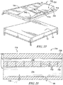
Fig. 22 is a perspective view of another bed assembly including an elevation system; and -
Fig. 23 is a sectional view of the elevation system ofFig. 22 taken along line 23-23 inFig. 22 . - An
illustrative bed assembly 10 is shown inFig. 1 and includes aframe 12 and a mattress supported by theframe 12. Thepatient support apparatus 10 is adapted for use in at-home patient care by providing a patient-care system 16. Thepatient care system 16 is configured to transform a conventional bed assembly into thebed assembly 10 to provide one or more bed functions that a patient may need while being treated for various medical conditions at home. As such, the patient-care system 16 includes asupport system 24 and anelevation system 26 that are configured to move themattress 14 relative to theframe 12 so that themattress 14 may support a patient in multiple postures during at-home patient care. As previously described, theframe 12 and themattress 14 illustratively provide a bed assembly that is used in a patient's home for personal uses. However, in other embodiments, thebed assembly 10 may be used in other settings such as, for example, a hospital, senior living/retirement homes, or any other suitable setting. - Illustratively, one such bed function provided by the
patient care system 16 may be the raising and lowering of thehead section 20,foot section 22, and/or other sections between thehead section 20 and thefoot section 22 of themattress 14. As such, at least a portion of the patient-care system 16 is arranged to underlie themattress 14 adjacent to movable sections of the mattress to provide the raising and lowering functions of themattress 14. Thesupport system 24 and theelevation system 26 are configured to cooperate to adjust a movable section, such as ahead section 20 and afoot section 22, of themattress 14 to an arrangement between a fully-lowered position, as shown inFig. 2 , and a fully-raised position, as shown inFig. 3 . - The
support system 24 includes atop plate 28, abase plate 30, and ahinge 32 arranged between afree end 34 of thesupport system 24 and afixed end 36 of thesupport system 24 as shown inFigs. 2 and 3 . Thetop plate 28 is relatively flat and is positioned under themattress 14 in engagement with a movable section of themattress 14. Illustratively, thetop plate 28 engages the head section of themattress 14 as shown inFigs. 2 and 3 . Thebase plate 30 is positioned below thetop plate 28 in engagement with theframe 12 of thebed assembly 10. Thehinge 32 is coupled to thetop plate 28 and thebase plate 30 at thefixed end 36 of thesupport system 24. Thetop plate 28 is coupled to thehinge 32 for pivotable movement about a support-system pivot axis 38 as thelife generator 26 moves thesupport system 24 and themattress 14 between the fully lowered position and the fully-raised position. The supportsystem pivot axis 38 is provided by thehinge 32 at thefixed end 36 such that thetop plate 28 moves away from thebase plate 30 at thefree end 34 while thetop plate 28 remains generally fixed relative to thebase plate 30 at thefixed end 36 as thesupport system 24 changes themattress 14 from the fully-lowered position to the fully-raised position. - As described above, the
elevation system 26 is configured to move thesupport system 24 to cause a movable section of themattress 14 to change to various positions relative to theframe 12. Theelevation system 26 is coupled to thesupport system 24 and provides a force on thesupport system 24 when activated to accomplish this objective. The force may be applied linearly on thesupport system 24, or the force may be applied on the support surface along a predetermined path. - A first embodiment of the
elevation system 26, in accordance with the present disclosure, is illustratively shown inFigs. 1-3 . Theelevation system 26 includes apneumatic bladder 40 and afluid source 42 coupled to thebladder 40. Thebladder 40 is positioned between thetop plate 28 and thebase plate 30. Thefluid source 42 is configured to provide fluid to thebladder 40 to fill thebladder 40 and cause thetop plate 28 to move relative to thebase plate 30. In this way, the movable section of themattress 14 is elevated. In some embodiments, thebladder 40 may be wrapped in acover 44 as shown inFigs. 2 and 3 and described in greater detail below. - In the illustrative embodiment, a single
pneumatic bladder 40 is provided between thetop plate 28 and thebase plate 30. However, in other embodiments,multiple bladders 40 may be used. Such bladder orbladders 40 may have any shape suitable to provide adequate force on thetop plate 28 to cause the movable section of themattress 14 to elevate. - In the illustrative embodiment, the
fluid source 42 is configured to provide an air source to inflate thebladder 40. However, in other embodiments, any suitable fluid source may be used to inflate thebladder 40. Thebladder 40 may be automatically inflated or deflated based on predetermined parameters. These parameters may be sensed by a series of sensors (not shown). The sensors may be coupled to a controller to determine if sensed values exceed predetermined thresholds that may require inflation or deflation of thebladder 40. One or more valves may be provided to allow fluid to flow selectively out of thebladder 40 so that thebladder 40 deflates as will be described in greater detail below. - As shown in
Figs, 4-6 , the patient-care unit 16 may further include acontrol system 66 configured to operate theelevation system 26. Thecontrol system 66 may be coupled to acollapsible siderail 18 as shown inFig. 1 or another component of patient-care system 16 or remotely. Theelevation system 26 may be activated via thecontrol system 66 by a user such as, for example, a caregiver or the patient. However, in other embodiments, theelevation system 26 may be activated remotely or automatically in response to one or more predetermined conditions or settings of the patient-care system 16. - The
control system 66 includes acontrol interface 68, acontrol housing 70, and avalve circuit 72 positioned within thecontrol housing 70 as shown inFigs. 4-6 . Thecontrol interface 68 includes a plurality ofswitches 73 configured to be operated by the user to inflate and deflate thebladder 40 as indicated by arrows also included on thecontrol interface 68. Thevalve circuit 72 is coupled to thefluid source 42 via aconduit 74 and theswitches 73 and is configured to inflate or deflate abladder 40 associated with one of the movable sections of themattress 14 depending on the switch activated by the user. - A schematic illustration of an
illustrative valve circuit 72 is shown inFig. 6 . Thevalve circuit 72 includes a head-section circuit 76 and a foot-section circuit 78. The head-section circuit 76 is configured to control raising and lowering of thehead section 20 while the foot-section circuit 78 is configured to control raising and lowering of thefoot section 22. In other embodiments, additional circuits may be provided to control raising and lowering of other sections of themattress 14. - The head-
section circuit 76 is coupled to thefluid source 42 and includes aninlet valve 80 and anoutlet valve 82 as shown inFig. 6 . The head-section circuit 76 is configured to direct fluid from thefluid source 42 to thebladder 40 in thehead section 20 when theswitch 73 associated with theinlet valve 80 is actuated to inflate thebladder 40 and raise thehead section 20. The head-section circuit 76 is configured to direct fluid out of thebladder 40 when theswitch 73 associated with theoutlet valve 82 is actuated to deflate thebladder 40 and lower thehead section 20. - The foot-
section circuit 78 is coupled to thefluid source 42 and includes aninlet valve 84 and anoutlet valve 86 as shown inFig. 6 . The foot-section circuit 78 is configured to direct fluid from thefluid source 42 to thebladder 40 in thefoot section 22 when theswitch 73 associated with theinlet valve 84 is actuated to inflate thebladder 40 and raise thefoot section 22. The foot-section circuit 78 is configured to direct fluid out of thebladder 40 when theswitch 73 associated with theoutlet valve 86 is actuated to deflate thebladder 40 and lower thefoot section 22. - The
valve circuit 72 may further include an emergency-release system 88 coupled to thebladder 40 as shown inFig. 7 . The emergency-release system 88 may be operated by a user in certain situations that may require thebladder 40 to deflate at a faster rate so that the patient lies flat on thepatient support apparatus 10. The emergency-release valve 88 includes aplug 90 and atether 92 coupled to theplug 90. Theplug 90 is sized and positioned to cover an aperture in thebladder 40. Thetether 92 may be pulled by a user to remove the plug from thebladder 40 so that the fluid inbladder 40 is released and the movable section of themattress 14 is lowered at a faster rate. - Referring now to
Figs. 8 and 9 , various types of fluid sources may be used to provide a flow of fluid to thebladder 40. Thefluid source 42 may include apump 44 as shown inFig. 8 . In the illustrative embodiment, thepump 44 is ahand pump 44 that is configured to be operated manually by a caregiver or the patient. In some embodiments, thepump 44 may include an automatic pump such as, for example, a diaphragm pump, a centrifugal pump, a displacement pump, a vacuum, or any other suitable pump. - The
hand pump 44 includes ahousing 46 and adiaphragm 48 positioned in a space defined by thehousing 46 as shown inFig. 8 . Thehousing 46 includes atop plate 50 and abase plate 52. Thediaphragm 48 provides a force on thehousing 46 that maintains spacing between thetop plate 50 and thebase plate 52. Thediaphragm 48 defines an internal space that holds fluid when thetop plate 50 and thebase plate 52 are spaced apart from one another. The caregiver or the patient may fillbladder 40 with fluid by applying an opposite force on thehousing 46 to compress thediaphragm 48 causing the fluid in the internal space to flow out of the diaphragm and in to thebladder 40. - Referring now to
Fig. 9 , another illustrative embodiment of afluid source 54 is shown. Thefluid source 54 includes ahousing 56, anair canister 58, and anactivator 60. Thehousing 56 is shaped to define aninternal space 62. Theair canister 58 is arranged to fit in theinternal space 62 of thehousing 56. Anaperture 64 is provided in thehousing 56 and theactivator 60 is sized to fit in theaperture 64. Theactivator 60 extends from thecanister 58 in theinternal space 62 through theaperture 64 to be accessed by a caregiver or the patient. To inflate thebladder 40, the caregiver or patient may actuate theactivator 60 by compressing theactivator 60 toward thecanister 58. Compressed air is then released from thecanister 58 to thebladder 40 to inflate thebladder 40. Depletedcanisters 58 may be discarded or refilled and reused in thefluid source 54. - Referring now to
Fig. 10 , another embodiment of anelevation system 226 is shown. Theelevation system 226 includes abladder 240 and afoam insert 242. Thebladder 240 has asheet 244 that is shaped to define aninternal space 246. Thefoam insert 242 is positioned in theinternal space 246 and has a shape that matches the shape of theinternal space 246 defined by thesheet 244 when thebladder 240 is inflated. - The
bladder 240 further includes aninlet valve 248 and anoutlet valve 250 coupled to thesheet 244 as shown inFig. 10 . In the illustrative embodiment, theinlet valve 248 is a one-way valve and is configured to permit air to flow into theinternal space 246 as thebladder 240 inflates. In the illustrative embodiment, theoutlet valve 250 is a one-way valve and is configured to permit air to flow out of theinternal space 246 as thebladder 240 deflates.Caps 252 are secured to thevalves internal space 246. In other embodiments, a two-way valve may be used such that only one valve and cap is provided. - The
foam insert 242 is made from any suitable foam material such as, for example, polyethylene or polyurethane. Thefoam insert 242 is configured to provide an outward force on thesheet 244. A caregiver or patient may raise and lower the movable section of themattress 14 by removing selectively one or both of thecaps 252 covering thevalves foam insert 244 maintains thebladder 240 in an inflated state when thecap 252 covering theinlet valve 248 is removed. The caregiver or patient may remove the cap covering theoutlet valve 250 and apply an opposite force on thebladder 240 and thefoam insert 242 to deflate thebladder 240. Once the movable section of themattress 14 is arranged at the desired angle, bothcaps 252 may be resecured to thevalves internal space 246 of thesheet 244. In other embodiments,fluid source bladder 240. In other embodiments, a vacuum (not shown) may be used to provide suction to remove fluid from the bladders. - In the illustrative embodiment, the
bladder 240 is divided into afirst bladder section 254, asecond bladder section 256, and athird bladder section 258 byrespective dividers Fig. 10 . Thefoam insert 242 is also divided into afirst foam section 260, asecond foam section 262, and athird foam section 264, which are positioned within the first, second, and third bladder sections, respectively. Each foam section is separated from one another by afirst divider 266 between the first and second foam sections and asecond divider 268 between the second and third foam sections. - The
dividers sheet 244 of thebladder 240 such that bladder sections are independent of one another. Additionally, aninlet valve 248 and anoutlet valve 250 are coupled to eachbladder section mattress 14. Although three bladder sections and three foam sections are included inelevation system 226, it should be appreciated that any suitable number of bladder sections and foam sections may be used. - Referring now to
Fig. 11 , another embodiment of anelevation system 326 is shown.Elevation system 326 is similar toelevation system 226 exceptelevation system 326 includes a plurality ofbladders 340 that are configured to couple selectively to one another to increase an elevation angle of the movable section of themattress 14. As such, similar reference numbers are used to describe features ofelevation system 326 that are similar toelevation system 226. - The
elevation system 326 includes afirst bladder 341, asecond bladder 343 and a plurality of foam inserts 342. Eachbladder sheet internal spaces internal spaces internal spaces sheets bladders - The
first bladder 341 includes abottom surface 372 and atop surface 374 that is angled relative to the bottom surface by anangle 376. Thesecond bladder 343 includes abottom surface 378 and atop surface 380 that is angled relative to the bottom surface by anangle 382. The first andsecond bladders total angle 384 of theelevation system 326 that corresponds to the elevation angle of the movable section of themattress 14. In the illustrative embodiment,angle 376 is equal toangle 382, however, in other embodiments, theangle 376 may not be equal toangle 382. It should be appreciated thatadditional bladders 340 may be added toelevation system 326 to further increase the elevation angle of the movable section of themattress 14. - Each
bladder inlet valve 348 and anoutlet valve 350 coupled to thesheets Fig. 11 . In the illustrative embodiment, theinlet valves 348 and theoutlet valves 350 cooperate with the foam inserts 342 to allow a caregiver or the patient inflate and deflate thebladders elevation system 226. In some embodiments,fluid source bladders - The
elevation system 326 further includesfasteners 370 that are configured to couple thefirst bladder 341 to thesecond bladder 343 as shown inFig. 11 . In the illustrative embodiment, thefasteners 370 are mechanical fasteners such as, for example, snaps. However, in other embodiments, thefasteners 370 may include any suitable coupling means such as, for example, a cover, Velcro®, adhesives, or magnets. - Another embodiment of an
elevation system 426, in accordance with the present disclosure, is shown inFigs. 12 and 13 . Theelevation system 426 is amechanical elevation system 426 and includes amount system 440, anactuator system 442, and anactuator mover 444. Themount system 440 has anupper mount 446 coupled to thetop plate 28 and alower mount 448 coupled to thebase plate 30. Theactuator system 442 is configured to move thetop plate 28 relative to thebase plate 30 to raise and lower a movable section of themattress 14. Theactuator mover 444 is coupled to theactuator system 442 and is configured to move theactuator system 442 to cause the raising and lowering of the movable section of themattress 14. - The
mount system 440 couples theactuator system 442 to thetop plate 28 and thebase plate 30 as shown inFig. 12 . Theactuator system 442 includes a pair ofleft support links upper mount 446 while support links 452, 456 are coupled tolower mount 448. Support links 450, 452 are pivotably mounted to one another about a first link-pivot axis 458. Support links 454, 456 are pivotably mounted to one another about a second link-pivot axis 460. - The
actuator mover 444 extends transversely from the left link-pivot axis 458 to the right link-pivot axis 460 as shown inFigs. 12 and 13 . Theactuator mover 444 includes amount 462 fixed near the left link-pivot axis 458 and threads that run along a length of theactuator mover 444. Theactuator mover 444 is threadingly engaged to the pair ofleft support links actuator mover 444 may be rotated aboutaxis 464 to raise and lower thetop plate 28 relative to thebase plate 30. The left link-pivot axis 458 and the rightlink pivot axis 460 move toward one another as theactuator mover 444 is rotated to raise the top plate and move away from one another as theactuator mover 444 is rotated oppositely to lower thetop plate 28. - Another embodiment of an
elevation system 526, in accordance with the present disclosure, is shown inFigs. 14-16 . Theelevation system 526 is amechanical elevation system 526 and includes amount system 540, anactuator system 542, and anactuator mover 544. Themount system 540 has anupper mount 546 coupled to thetop plate 28 and alower mount 548 coupled to thebase plate 30. Theactuator system 542 is configured to move thetop plate 28 relative to thebase plate 30 to raise and lower a movable section of themattress 14. Theactuator mover 544 is coupled to themount system 540 and is configured to move themount system 540 and theactuator system 542 to cause the raising and lowering of the movable section of themattress 14. - The
mount system 540 couples theactuator system 542 to thetop plate 28 and thebase plate 30 as shown inFig. 14 . Theupper mount 546 is fixed to thetop plate 28. Thelower mount 548 is threadingly mounted to theactuator mover 544. Theactuator system 542 includes one or more support links that have afirst end 552 coupled to theupper mount 546 and asecond end 554 coupled to thelower mount 548. - The
actuator mover 544 is configured to rotate about a actuator-mover axis 556 to raise or lower thetop plate 28 relative to thebase plate 30 depending on the rotation direction. Theactuator mover 544 rotates to move thesecond end 554 of theactuator system 542 and thelower mount 548 toward thefixed end 36 of thesupport system 24 to raise thetop plate 28 and thus movable section of themattress 14. Theactuator mover 544 rotates oppositely to move thesecond end 554 of theactuator system 542 and thelower mount 548 away from the fixedend 36 of thesupport system 24 to lower thetop plate 28 and thus movable section of themattress 14. - The
actuator mover 544 may be rotated by apowered device 560 such as, for example, a drill or a motor as shown inFig. 15 . Theactuator mover 544 may also be rotated manually by adevice 562 such as, for example, a hand crank. In other embodiments, any suitable device or method for rotating theactuator mover 544 may be used. - Another embodiment of an
elevation system 626, in accordance with the present disclosure, is shown inFigs. 17 and 18 . Theelevation system 626 is amechanical elevation system 626 and includes amount system 640 and anactuator system 642. Themount system 640 is configured to support theactuator system 642. Theactuator system 642 is configured to raise and lower a movable section of themattress 14. - The
mount system 640 includes a head-section support 644 and a foot-section support 646 that is substantially similar to the head-section support 644 as shown inFigs. 17 and 18 . Eachsupport left rod 648 positioned on a left lateral side of the bed assembly, aright rod 650 positioned on a right lateral side of the bed assembly, and aconnector rod 652 underlying the bed assembly. The left andright rods connector rod 652 extends from theleft rod 648 to theright rod 650 and rests on ground to support the left andright support rods connector rod 650 may be configured to telescope transversely relative to the bed assembly to accommodate bed assemblies of various widths. - The
actuator system 642 is coupled to the left andright support rods mattress 14 and is configured to lift a movable section of themattress 14 upwardly as shown inFigs. 17 and 18 . Theactuator system 642 includes anactuator 654, abelt 656, and amount 658. Theactuator 654 is coupled to one of the support rods and is configured to actuate thebelt 656 to decrease a length of thebelt 656 and raise the movable section of themattress 14. Thebelt 656 is arranged under the movable section of the mattress and is configured to raise and lower the movable section relative to theframe 12. Themount 658 secures theactuator 654 and thebelt 656 to the left andright support rods - In the illustrative embodiment, the
actuator 654 includes a manual hand crank 664 that may be turned to decrease a length of thebelt 656 and raise the movable section of themattress 14. However, in other embodiments, any suitable device may be used to actuate thebelt 656 such as, for example, a powered motor. - As previously described, the
support system 24 may further include acover 94 that may be used with any of theelevation systems Figs. 19-21 . Thecover 94 includes asheet 96 and aretainer 98. Thesheet 96 is wrapped around thesupport system 24 including thetop plate 28, thebase plate 30, and thehinge 32. Theretainer 98 is coupled to thesupport system 24 and thesheet 96 and is configured to secure selectively thesheet 96 to thesupport system 24. - In the illustrative embodiment, the
retainer 98 includes Velcro® strips coupled to thesheet 96 and thesupport system 24 as shown inFig. 19 . However, in other embodiments, other types of retainers or fasteners may be used such as, for example, mechanical fasteners, adhesives, or magnets. Threelongitudinal strips 102 are coupled to thesupport system 24 while complementarytransverse strips 104 are coupled to eachend sheet 96. Eachtransverse strip 104 is coupled to thelongitudinal strips 102 to retain thesheet 96 on thesupport system 24 as shown inFig. 20 . - The
sheet 96 may be sized and/or located via theretainer 98 to restrict the elevation angle of the movable section of themattress 14 by limiting the distance thetop plate 28 may pivot relative to thebase plate 30 about thehinge 32 as shown inFig. 21 . For example, in the illustrative embodiment shown inFig. 19 , indicator marks 100 are provided on thesupport system 24 adjacent to thelongitudinal strips 104 of theretainer 98. The indicator marks 100 include afirst set 110 associated with a first elevation angle of the movable section and asecond set 112 associated with a second elevation angle of the movable section. Thesecond end 108 of thesheet 96 may be aligned with thefirst set 110 to limit the elevation angle of the movable section to the first elevation angle. Thesecond end 108 of thesheet 96 may be aligned with thesecond set 112 to limit the elevation angle of the movable section to the second elevation angle. The second elevation angle is greater than the first elevation angle due to increased spacing between the first and second ends of thesheet 96. Additional sets of indicator marks 100 may be provided to increase adjustability of the elevation angle of the movable section of themattress 14 via thecover 94. - Another embodiment of a patient-
care system 716, in accordance with the present disclosure, is shown inFigs. 22-23 . Thepatient care system 716 is configured to transform a conventional bed assembly into thebed assembly 10 to provide one or more bed functions that a patient may need while being treated for various medical conditions at home. As such, the patient-care system 16 includes amattress topper 718 that is configured to support a patient in multiple postures during at-home patient care. As previously described, theframe 12 and themattress 14 illustratively provide a bed assembly that is used in a patient's home for personal uses. However, in other embodiments, thebed assembly 10 may be used in other settings such as, for example, a hospital, senior living/retirement homes, or any other suitable setting. - The
mattress topper 718 is arranged to overlie themattress 14 and includes one or more movable sections to provide elevation for various parts of the patient. Themattress topper 718 includes apillow section 724 and anelevation system 726 that are configured to cooperate with the patient to provide elevation for a patient at ahead section 20 and afoot section 22 of themattress topper 716. - The
pillow section 724 includes a pillow-top overlay 728 and apillow midsection 730 as shown inFig. 23 . The pillow-top overlay 728 provides a comfortable surface for a patient. Thepillow mid-section 730 is spaced apart from the pillow top overlay and is formed to include a plurality ofchannels 732 to communicate fluid between various bladders in themattress topper 716 as will be explained in greater detail below. - The
elevation system 726 includes a plurality of bladders formed in themattress topper 716 and is configured to cooperate with the patient's body weight distribution to raise and lower thehead section 20 and thefoot section 22 of themattress topper 716. Theelevation system 726 includes aprimary bladder 734 coupled to afluid source 736 and a plurality ofsecondary bladders 738 as shown inFigs. 22 and 23 . Theprimary bladder 734 receives fluid from thefluid source 736 and provides the fluid to thesecondary bladders 738 through thechannels 732 depending on the patient' body weight distribution over themattress topper 716. Thesecondary bladders 738 are configured to inflate and/or deflate in response to the patient's body weight distribution and an amount of fluid in theelevation system 726. - The plurality of
secondary bladders 738 includes a head-section bladder 740, a foot-section bladder 742, and left and right side-bolsterbladders Fig. 22 . Each of thebladders primary bladder 734 such that the patient may inflate and/or deflate one or more of the bladders in response to changing the patient's body weight distribution over themattress topper 716 and/or changing the amount of fluid in theelevation system 724. In other embodiments, thesecondary bladders 738 may be independent of one another and may include valves to regulate fluid flow into and out of eachbladder - For example, the
primary bladder 734 may be filled with fluid while thesecondary bladders 738 contain no fluid. In this situation, the patient may be laid flat on themattress topper 716. Additional fluid may be added to theprimary bladder 734 from thefluid source 736. The added fluid may flow from theprimary bladder 734, through thechannels 732 and into one or more of thesecondary bladders 738 depending on the patient's body weight distribution over themattress topper 716. The patient may control or adjust the elevation of thebladders - The
fluid source 736 may includefluid source 42,fluid source 54, or any other suitable fluid source. Additionally, theelevation system 726 may further includecontrol system 66 to control input and output of fluid from theprimary bladder 734. - Embodiments of the invention can be described with reference to the following numbered clauses, with preferred features laid out in the dependent clauses:
- 1. A bed assembly comprising:
- a frame,
- a mattress supported by the frame, and
- a patient-care system including a support system and an elevation system positioned selectively between the frame and the mattress and configured to provide means for raising at least one movable section of the mattress from a fully-lowered position, in which the mattress is arranged generally parallel to the frame, to a fully-raised position, in which the at least one movable section of the mattress is arranged at an angle relative to the frame.
- 2. The patient mattress of clause 1, wherein the support system includes a top plate, a base plate, and a hinge positioned between a free end of the support system and a fixed end of the support system and a elevation system coupled to the support system and configured to move the support system to raise the at least one movable section of the mattress in response to an activation of the elevation system.
- 3. The bed assembly of clause 2, wherein the elevation system includes at least one pneumatic bladder positioned between the top plate and the base plate and at least one valve coupled to the at least one pneumatic bladder.
- 4. The bed assembly of clause 3, wherein the elevation system further includes at least one pneumatic actuator coupled to the at least one pneumatic bladder and configured to change the at least one pneumatic bladder from a deflated state to and inflated state to move the movable section of the mattress towards the fully-raised position.
- 5. The bed assembly of clause 4, wherein the at least one pneumatic actuator includes a housing, a canister of fluid, and an activator, the housing defines an internal space and the canister is positioned in the internal space and coupled to the pneumatic bladder with a conduit such that the canister is configured to release the fluid into the pneumatic bladder in response to triggering the activator.
- 6. The bed assembly of either clause 4 or clause 5, wherein the pneumatic actuator is a manual hand pump.
- 7. The bed assembly of either clause 4 or clause 5, wherein the pneumatic actuator is an automatic air-pump.
- 8. The bed assembly of any one of clauses 3 to 7, wherein the bladder has a sheet that defines an internal space and the elevation system further includes a foam insert positioned within the internal space of the bladder and the foam insert is configured to apply an outward force on the sheet to expand the bladder to the inflated state.
- 9. The bed assembly of clause 8, wherein the elevation system includes an inlet valve, an outlet value, and a valve cap configured to cover the outlet valve, and the inlet valve and the outlet valve are both one way valves such that the bladder is configured to remain inflated while the valve cap covers the outlet valve.
- 10. The bed assembly of clause 9, wherein the bladder is configured to deflate when the valve cap is removed from the outlet valve and a force is applied on the bladder and the foam insert to compress the foam insert.
- 11. The bed assembly of any one of clauses 3 to 7, wherein the elevation system includes a plurality of bladders each having a sheet that defines an internal space and plurality of foam inserts, at least one foam insert is positioned within the internal space of the bladders, and wherein each foam insert is configured to apply an outward force on the bladders to expand each bladder to the inflated state.
- 12. The bed assembly of clause 11, wherein the elevation system further includes at least one fastener between adjacent bladders to couple each of the bladders together.
- 13. The bed assembly of clause 3, wherein the elevation system includes a first pneumatic pump coupled to a first pneumatic bladder in a head section of the mattress and a second pneumatic pump coupled to a second pneumatic bladder in a foot section of the mattress, and the at least one valve is configured to open to manually release air contained within at least one of the pneumatic bladders.
- 14. The bed assembly of clause 3, wherein the elevation system includes a single pneumatic pump coupled to a first pneumatic bladder in a head section of the mattress and a second pneumatic bladder in a foot section of the mattress, and a first valve is configured to selectively switch between the first and second pneumatic bladders to inflate one of the first and second pneumatic bladders while a second valve is configured to open to manually release air contained within at least one of the pneumatic bladders.
- 15. The bed assembly of clause 3, wherein the bed assembly further includes a control panel and the elevation system includes a first pneumatic pump coupled to a first pneumatic bladder in a head section of the mattress and a second pneumatic pump coupled to a second pneumatic bladder in a foot section of the mattress, and a first valve is configured to open to manually deflate the first bladder upon activation of a first button on the control panel and a second valve is configured to open to manually deflate the second bladder upon activation of a second button on the control panel.
- 16. The bed assembly of any one of clauses 3 to 15, wherein the elevation system further includes a release system coupled to the pneumatic bladder, and wherein the valve is configured to allow fluid to flow out of the bladder at a first flowrate and the release system is configured to allow fluid to flow out of the bladder at a second flowrate, and the second flowrate is greater than the first flowrate.
- 17. The bed assembly of
clause 16, wherein the release system includes a plug coupled to the pneumatic bladder and a cord having a first end coupled to the plug and a second end coupled to a pull tab. - 18. The bed assembly of clause 2, wherein the elevation system includes a mount system and an actuator system.
- 19. The bed assembly of
clause 18, wherein the mount system includes an upper mount coupled to the top plate and a lower mount coupled to the base plate. - 20. The bed assembly of either
clause 18 or clause 19, wherein the actuator system includes a pair of left support links and a pair of right support links, the left support links coupled for pivotable movement relative to one another about a first support link axis, and the right support links coupled for pivotable movement relative to one another about a second support link axis. - 21. The bed assembly of
clause 20, wherein elevation system further includes an actuator mover coupled to the left support links and the right support links and is configured to move the first support link axis and the second support link axis toward one another to raise the top plate. - 22. The bed assembly of clause 19, wherein the elevation system further includes an actuator mover coupled to the lower mount and configured to move the lower mount to raise and lower the top plate.
- 23. The bed assembly of
clause 18, wherein the mount system includes a left support rod arranged on a left lateral side of the mattress, a right support rod arranged on a right lateral side of the mattress, and a connector rod underlying the mattress. - 24. The bed assembly of
clause 23, wherein the left support rod, the right support rod, and the connector rod are telescopic. - 25. The bed assembly of either
clause 23 orclause 24, wherein the actuator system includes an actuator, a belt, and a mount configured to secure the actuator and the belt to the left and right support rods. - 26. The bed assembly of clause 25, wherein the belt is arranged to lie under a movable section of the mattress and the actuator is configured to actuate the belt to decrease a length of the belt and raise the movable section.
- 27. The bed assembly of any one of
clauses 18 to 26, wherein the actuator mover includes a hand crank. - 28. The bed assembly of
clause 18, wherein the actuator mover includes a motor coupled to a power source. - 29. The bed assembly of any one of clauses 2 to 28, wherein the support system further includes a cover having a first end and a second end spaced apart from the first end a predetermined distance so that a length of the cover corresponds to a elevation angle of the top plate relative to the base plate.
- 30. The bed assembly of clause 29, wherein the cover is configured to retain the top plate at the elevation angle to position the movable section of the mattress in the fully-raised position.
- 31. The bed assembly of
clause 30, wherein the cover includes a sheet defining the length of the cover and at least one retainer coupled to the support system to fix the cover to the support system at the predetermined distance. - 32. The bed assembly of clause 31, wherein the retainer includes longitudinal strips coupled to the support system and transverse strips coupled to the sheet, and a plurality of indicator marks are provided adjacent to the longitudinal strips.
- 33. The bed assembly of
clause 32, wherein the indicator marks include a first set associated with a first angle of the mattress and a second set associated with a second angle of the mattress and the second end of the sheet is configured to align selectively with one of the sets to restrict the elevation angle of the mattress to one of the first and second angles associated with the first and second set. - 34. An at-home bed assembly comprising:
- a frame,
- a mattress supported by the frame, and
- an patient-care system positioned selectively above the mattress, the patient-care system including a pillow section and an elevation system, the elevation system configured to adjust at least one movable section from a fully-lowered position, in which the pillow section is arranged generally parallel to the frame and mattress, to a fully-raised position, in which the at least one movable section of the mattress is arranged at an angle relative to the frame and the mattress in response to a patient's body weight distribution on the patient-care system.
- 35. The bed assembly of
clause 34, wherein the elevation system includes a primary bladder and a plurality of secondary bladders spaced apart from the primary bladder. - 36. The bed assembly of clause 35, wherein a plurality of channels extend from the primary bladder to the secondary bladders to communicate fluid from the primary bladder to the secondary bladders.
- 37. The bed assembly of either clause 35 or
clause 36, wherein secondary bladders include a head-section bladder, a foot-section bladder, and a pair of side-bolster bladders. - 38. The bed assembly of clause 37, wherein each of the head-section bladder, foot-section bladder, and side-bolster bladders is independently inflatable.
- Although this disclosure refers to specific embodiments, it will be understood by those skilled in the art that various changes in form and detail may be made.
Claims (15)
- A bed assembly comprising:a frame,a mattress supported by the frame, anda patient-care system including a support system and an elevation system insertable between the frame and the mattress, the elevation system and support system cooperating to move at least a portion of the mattress from a fully-lowered position, in which the mattress is arranged generally parallel to the frame, to a fully-raised position, in which the at least one movable section of the mattress is arranged at an angle relative to the frame.
- The patient mattress of claim 1, wherein the support system includes a top plate, a base plate, and a hinge positioned between a free end of the support system and a fixed end of the support system and a elevation system coupled to the support system and configured to move the support system to raise the at least one movable section of the mattress in response to an activation of the elevation system.
- The bed assembly of claim 2, wherein the elevation system includes at least one pneumatic bladder positioned between the top plate and the base plate and at least one valve coupled to the at least one pneumatic bladder.
- The bed assembly of claim 3, wherein the bladder has a sheet that defines an internal space and the elevation system further includes a foam insert positioned within the internal space of the bladder and the foam insert is configured to apply an outward force on the sheet to expand the bladder to the inflated state.
- The bed assembly of claim 3, wherein the elevation system includes a first pneumatic pump coupled to a first pneumatic bladder in a head section of the mattress and a second pneumatic pump coupled to a second pneumatic bladder in a foot section of the mattress, and the at least one valve is configured to open to manually release air contained within at least one of the pneumatic bladders.
- The bed assembly of claim 3, wherein the elevation system includes a single pneumatic pump coupled to a first pneumatic bladder in a head section of the mattress and a second pneumatic bladder in a foot section of the mattress, and a first valve is configured to selectively switch between the first and second pneumatic bladders to inflate one of the first and second pneumatic bladders while a second valve is configured to open to manually release air contained within at least one of the pneumatic bladders.
- The bed assembly of any one of claims 3 to 6, wherein the elevation system further includes a release system coupled to the pneumatic bladder, and wherein the valve is configured to allow fluid to flow out of the bladder at a first flowrate and the release system is configured to allow fluid to flow out of the bladder at a second flowrate, and the second flowrate is greater than the first flowrate.
- The bed assembly of claim 2, wherein the elevation system includes a mount system and an actuator system.
- The bed assembly of claim 8, wherein the mount system includes an upper mount coupled to the top plate and a lower mount coupled to the base plate.
- The bed assembly of either claim 8 or claim 9, wherein the actuator system includes a pair of left support links and a pair of right support links, the left support links coupled for pivotable movement relative to one another about a first support link axis, and the right support links coupled for pivotable movement relative to one another about a second support link axis.
- The bed assembly of claim 10, wherein the elevation system further includes an actuator mover coupled to the left support links and the right support links and is configured to move the first support link axis and the second support link axis toward one another to raise the top plate.
- The bed assembly of claim 9, wherein the elevation system further includes an actuator mover coupled to the lower mount and configured to move the lower mount to raise and lower the top plate.
- The bed assembly of claim 8, wherein the mount system includes a left support rod arranged on a left lateral side of the mattress, a right support rod arranged on a right lateral side of the mattress, and a connector rod underlying the mattress.
- The bed assembly of claim 13, wherein the actuator system includes an actuator, a belt, and a mount configured to secure the actuator and the belt to the left and right support rods.
- The bed assembly of any one of claims 2 to 14, wherein the support system further includes a cover having a first end and a second end spaced apart from the first end a predetermined distance so that a length of the cover corresponds to a elevation angle of the top plate relative to the base plate and wherein preferably the cover is configured to retain the top plate at the elevation angle to position the movable section of the mattress in the fully-raised position.
Applications Claiming Priority (1)
| Application Number | Priority Date | Filing Date | Title |
|---|---|---|---|
| US201862739337P | 2018-09-30 | 2018-09-30 |
Publications (2)
| Publication Number | Publication Date |
|---|---|
| EP3628296A1 true EP3628296A1 (en) | 2020-04-01 |
| EP3628296B1 EP3628296B1 (en) | 2023-05-10 |
Family
ID=68084686
Family Applications (1)
| Application Number | Title | Priority Date | Filing Date |
|---|---|---|---|
| EP19200253.3A Active EP3628296B1 (en) | 2018-09-30 | 2019-09-27 | Structures for causing movement of elements of a bed |
Country Status (3)
| Country | Link |
|---|---|
| US (1) | US11357682B2 (en) |
| EP (1) | EP3628296B1 (en) |
| CN (1) | CN212166033U (en) |
Cited By (1)
| Publication number | Priority date | Publication date | Assignee | Title |
|---|---|---|---|---|
| EP3632390A3 (en) * | 2018-10-01 | 2020-07-15 | Hill-Rom Services, Inc. | Method and apparatus for upgrading a bed to include moveable components |
Families Citing this family (2)
| Publication number | Priority date | Publication date | Assignee | Title |
|---|---|---|---|---|
| CN112471819A (en) * | 2020-11-27 | 2021-03-12 | 李海芳 | Adjustable bed |
| CN112971442B (en) * | 2021-04-23 | 2022-09-02 | 上海爱舒床垫集团有限公司 | Multifunctional mattress |
Citations (6)
| Publication number | Priority date | Publication date | Assignee | Title |
|---|---|---|---|---|
| US3781928A (en) * | 1971-04-05 | 1974-01-01 | Erik Pettersson | Device for raising the head end and/or foot end of a bed |
| GB1474018A (en) * | 1974-05-24 | 1977-05-18 | Watkins Watson Ltd | Beds or like support appliances |
| WO1988009140A1 (en) * | 1987-05-26 | 1988-12-01 | Williamson Robert M | An adjustable bed system |
| US20090089930A1 (en) * | 2007-10-09 | 2009-04-09 | Eduardo Rene Benzo | Bed with Adjustable Patient Support Framework |
| US20170245656A1 (en) * | 2016-02-26 | 2017-08-31 | Hill-Rom Services, Inc. | Sleep disorder treatment devices, systems, and methods |
| EP3466391A1 (en) * | 2017-10-04 | 2019-04-10 | Hill-Rom Services, Inc. | Apparatus for adding hospital bed functionality to an at-home bed |
Family Cites Families (110)
| Publication number | Priority date | Publication date | Assignee | Title |
|---|---|---|---|---|
| DE1987293U (en) | 1968-06-12 | Albert Vogtle S. Co 7332 Eislmgen | Air bellows for backs and head supports on beds, etc. | |
| US948644A (en) | 1908-06-23 | 1910-02-08 | Andrew Bjornstad | Mattress. |
| US1610898A (en) | 1923-10-05 | 1926-12-14 | Cleveland R Steiner | Pneumatic mattress |
| US2612645A (en) | 1949-09-13 | 1952-10-07 | Boland Gus Leslie | Reclining air cushion |
| US2887692A (en) | 1956-05-23 | 1959-05-26 | Gosman Clarence Berveir | Inflatable cushion or the like |
| GB1126364A (en) | 1965-10-18 | 1968-09-05 | Uniroyal Ltd | An inflatable cushion, seat, mattress or other like article |
| US3392412A (en) | 1967-01-12 | 1968-07-16 | Aymar Julian Robert | Adjustable bedrest |
| US3606623A (en) | 1970-01-09 | 1971-09-21 | Surgical Dynamics Inc | Adjustable bedrest with improved bellows structure |
| US3667075A (en) | 1970-02-24 | 1972-06-06 | Wesley D Ballard | Mattress spring bellows assembly as for hospitals, and the like |
| US4150284A (en) | 1977-04-28 | 1979-04-17 | Texas Instruments Incorporated | Medical patient condition monitoring system |
| US4151407A (en) | 1977-04-28 | 1979-04-24 | Texas Instruments Incorporated | Low-power, infrared information transmission system |
| US4165125A (en) | 1977-06-08 | 1979-08-21 | National Seating Company | Slipover headrest pillow assembly |
| JPS5438512U (en) | 1977-08-19 | 1979-03-14 | ||
| US4142263A (en) | 1977-11-25 | 1979-03-06 | Maine Ideas Incorporated | Bed-mattress elevating system and the like |
| US4216462A (en) | 1978-03-06 | 1980-08-05 | General Electric Company | Patient monitoring and data processing system |
| US4183015A (en) | 1978-06-26 | 1980-01-08 | Hill-Rom Company, Inc. | Side guard for bed including means for controlling remote electrical devices |
| US4228426A (en) | 1978-09-29 | 1980-10-14 | Roberts William A | Hospital bed monitor |
| US4225953A (en) | 1978-09-29 | 1980-09-30 | Simon William F | Personnel locator |
| US4237344A (en) | 1979-04-20 | 1980-12-02 | Hospital Communication Systems, Inc. | Rapid response health care communications system |
| US4331953A (en) | 1979-12-26 | 1982-05-25 | The Boeing Company | Communication system for use in hazardous confined areas |
| US4309783A (en) | 1980-02-06 | 1982-01-12 | Teledyne Industries, Inc. | Adjustably conformable bed |
| US4298863A (en) | 1980-02-10 | 1981-11-03 | St. Anthony Hospital Systems | Portable patient call |
| US5062151A (en) | 1983-01-13 | 1991-10-29 | Fisher Berkeley Corporation | Communication system |
| US4601064A (en) | 1983-01-13 | 1986-07-15 | Fisher Berkeley Corporation | Communication system |
| US4527298A (en) | 1982-03-18 | 1985-07-09 | Moulton Lee A | Electro pneumatic bed |
| US4649385A (en) | 1982-08-13 | 1987-03-10 | Teloc R & D Ltd. | Electronic locating system for persons receiving telephone calls |
| JPS5993524U (en) | 1982-12-15 | 1984-06-25 | 狩野 千世子 | Air mat type bed operated by computer |
| US4598275A (en) | 1983-05-09 | 1986-07-01 | Marc Industries Incorporated | Movement monitor |
| US4577185A (en) | 1983-07-29 | 1986-03-18 | Saint Margaret Hospital | Construction for alerting health-care professionals |
| US4554693A (en) | 1983-12-19 | 1985-11-26 | American Fast Print Limited | Mattress, box springs fabric |
| US4593273A (en) | 1984-03-16 | 1986-06-03 | Narcisse Bernadine O | Out-of-range personnel monitor and alarm |
| US4578671A (en) | 1984-12-05 | 1986-03-25 | International Business Machines Corp. | Remote indicating low battery voltage enunciator method and apparatus |
| US4680790A (en) | 1985-08-22 | 1987-07-14 | Joerns Healthcare, Inc. | Bedside control module for healthcare stations and the like |
| US5103108A (en) | 1985-10-17 | 1992-04-07 | Crimmins James W | Distributed infrared communication system |
| US4967195A (en) | 1986-05-08 | 1990-10-30 | Shipley Robert T | Hospital signaling and communications system |
| US4955000A (en) | 1986-07-17 | 1990-09-04 | Nac Engineering And Marketing, Inc. | Ultrasonic personnel location identification system |
| US4814751A (en) | 1987-02-27 | 1989-03-21 | Wildlife Materials, Inc. | Patient tracking system |
| US4850040A (en) | 1987-07-01 | 1989-07-18 | Inncom International, Inc. | Infrared remote control system for activating and deactivating one or more devices in a single enclosed space |
| JPH01238859A (en) | 1988-03-18 | 1989-09-25 | Sanei Seisakusho:Kk | Bed |
| DE3861791D1 (en) | 1988-05-05 | 1991-03-28 | Hewlett Packard Gmbh | DIGITAL ADDRESSABLE ELECTRONIC DEVICE. |
| US4877288A (en) | 1988-09-06 | 1989-10-31 | Susan Lee | Lounge chair cover |
| US4998939A (en) | 1988-09-28 | 1991-03-12 | R & P Joint Venture | Hospital bed with guard rail actuated safety apparatus |
| US5153584A (en) | 1989-03-17 | 1992-10-06 | Cardiac Evaluation Center, Inc. | Miniature multilead biotelemetry and patient location system |
| US5124991A (en) | 1989-03-30 | 1992-06-23 | Photonics Corporation | Error correction for infrared data communication |
| US4932089A (en) | 1989-08-02 | 1990-06-12 | Laviero Frank D | Beach pillow |
| US4990892A (en) | 1989-08-07 | 1991-02-05 | Westcom, A Division Of Westside Communications Of Jacksonville, Inc. | Personnel locator system |
| US4998095A (en) | 1989-10-19 | 1991-03-05 | Specific Cruise Systems, Inc. | Emergency transmitter system |
| US5036852A (en) | 1989-12-08 | 1991-08-06 | Leishman Mark L | Medical equipment monitor apparatus and method |
| US5012539A (en) | 1990-02-13 | 1991-05-07 | Grigg Ellen S | Inflatable multi-purpose medical support pillow |
| US5086290A (en) | 1990-03-08 | 1992-02-04 | Murray Shawn G | Mobile perimeter monitoring system |
| US5060174A (en) | 1990-04-18 | 1991-10-22 | Biomechanics Corporation Of America | Method and apparatus for evaluating a load bearing surface such as a seat |
| JPH04297257A (en) | 1991-03-27 | 1992-10-21 | Koshin Rubber Kk | Nursing instrument |
| US5144284A (en) | 1991-05-22 | 1992-09-01 | Hammett Rawlings H | Patient-monitoring bed covering device |
| US5253656A (en) | 1991-05-23 | 1993-10-19 | Rincoe Richard G | Apparatus and method for monitoring contact pressure between body parts and contact surfaces |
| US5137033A (en) | 1991-07-15 | 1992-08-11 | Norton John L | Patient monitoring device |
| US5184112A (en) | 1991-09-11 | 1993-02-02 | Gaymar Industries, Inc. | Bed patient position monitor |
| US5269388A (en) | 1991-11-12 | 1993-12-14 | Stress-Tek, Inc. | Weighing bed |
| US5170522A (en) | 1991-12-16 | 1992-12-15 | Select Comfort Corporation | Air adjustable bed |
| US5415167A (en) | 1992-01-10 | 1995-05-16 | Wilk; Peter J. | Medical system and associated method for automatic diagnosis and treatment |
| US5195198A (en) | 1992-01-15 | 1993-03-23 | Stryker Corporation | Fail-safe bed motion control circuit having a microprocessor |
| US5276432A (en) | 1992-01-15 | 1994-01-04 | Stryker Corporation | Patient exit detection mechanism for hospital bed |
| US5353012A (en) | 1992-05-14 | 1994-10-04 | Bartronix, Inc. | Bed position and activity sensing apparatus |
| US5577278A (en) | 1992-07-22 | 1996-11-26 | Princeton Products Inc. | Portable, integrated, universally adjustable position control system |
| US5311625A (en) * | 1992-07-22 | 1994-05-17 | Truman Products | Portable, integrated, universally adjustable position control system |
| DE69318850T2 (en) | 1992-12-11 | 1998-10-22 | Siemens Medical Systems Inc | DOCKING STATION FOR PATIENT MONITORING SYSTEM |
| US5838223A (en) | 1993-07-12 | 1998-11-17 | Hill-Rom, Inc. | Patient/nurse call system |
| US5345630A (en) | 1993-07-15 | 1994-09-13 | Jack Healy | Quick inflatable air mattress |
| US5715548A (en) | 1994-01-25 | 1998-02-10 | Hill-Rom, Inc. | Chair bed |
| US5490295A (en) | 1994-04-15 | 1996-02-13 | Boyd; Dennis | Water mattress and air mattress construction |
| CA2125300C (en) | 1994-05-11 | 1999-10-12 | Douglas J. Ballantyne | Method and apparatus for the electronic distribution of medical information and patient services |
| US5432967A (en) | 1994-06-20 | 1995-07-18 | Raftery Design, Inc. | Multiple position support cushion |
| US5528783A (en) | 1994-07-11 | 1996-06-25 | Kunz; Richard D. | Inflatable head and torso support |
| US6125350A (en) | 1995-06-02 | 2000-09-26 | Software For Surgeons | Medical information log system |
| US7017208B2 (en) | 1995-08-04 | 2006-03-28 | Hill-Rom Services, Inc. | Hospital bed |
| US5942986A (en) | 1995-08-09 | 1999-08-24 | Cedars-Sinai Medical Center | System and method for automatic critical event notification |
| US5944659A (en) | 1995-11-13 | 1999-08-31 | Vitalcom Inc. | Architecture for TDMA medical telemetry system |
| US5621931A (en) | 1995-12-12 | 1997-04-22 | Hamilton; Samantha | Mattress stabilizing bedskirt assembly having detachably attachable skirt components |
| US5936539A (en) | 1996-03-19 | 1999-08-10 | Siemens Medical Systems, Inc. | Method and apparatus for automatic configuration of a network node |
| US5877675A (en) | 1996-08-29 | 1999-03-02 | Jansys, Inc. | Wireless healthcare communication system |
| US6097308A (en) | 1996-12-04 | 2000-08-01 | Data Critical Corp. | Pager to computer link apparatus |
| US5933488A (en) | 1997-04-18 | 1999-08-03 | Siemens Information | Automated method and arrangement for integrating a telephone system with an announcement system |
| US5844488A (en) | 1997-09-23 | 1998-12-01 | Musick; Jeff L. | Bed sensor and alarm |
| US5963137A (en) | 1998-02-10 | 1999-10-05 | Waters, Sr.; Joe Cleveland | Alarm device for monitoring an individual's movement and/or need for assistance |
| US6111509A (en) | 1998-02-26 | 2000-08-29 | Bed-Check Corporation | Microprocessor based bed patient monitor |
| US6142592A (en) | 1998-05-19 | 2000-11-07 | Endress & Hauser Gmbh & Co Kg | Instrument system |
| US6093146A (en) | 1998-06-05 | 2000-07-25 | Matsushita Electric Works, Ltd. | Physiological monitoring |
| US6009873A (en) | 1998-08-27 | 2000-01-04 | Neviaser; Thomas J. | Bed sore treatment and prevention method and apparatus |
| US6131219A (en) | 1999-03-03 | 2000-10-17 | Roberts; Janet H. | Inflatable pillow |
| US6208250B1 (en) | 1999-03-05 | 2001-03-27 | Hill-Rom, Inc. | Patient position detection apparatus for a bed |
| US6133837A (en) | 1999-03-05 | 2000-10-17 | Hill-Rom, Inc. | Patient position system and method for a support surface |
| CA2311187A1 (en) | 1999-08-12 | 2001-02-12 | Hill-Rom, Inc. | Ambulatory assist arm for a bed |
| EP2140847B1 (en) | 2000-11-07 | 2012-07-25 | Tempur World, LLC | Therapeutic mattress assembly |
| ATE463779T1 (en) | 2001-08-03 | 2010-04-15 | Hill Rom Services Inc | PATIENT POINT OF CARE COMPUTER SYSTEM |
| US6739005B2 (en) | 2001-09-04 | 2004-05-25 | Banyan Licensing Lc | Bed with adjustable elevation components |
| US6684425B2 (en) | 2002-02-14 | 2004-02-03 | Edmund Scott Davis | Mattress retainer for adjustable bed |
| US20030196270A1 (en) | 2002-04-04 | 2003-10-23 | Banyan Licensing Lc | Inflatable bed support |
| US20050114998A1 (en) * | 2002-04-04 | 2005-06-02 | Banyan Licensing Lc | Inflatable bedrest |
| WO2004021952A2 (en) | 2002-09-06 | 2004-03-18 | Hill-Rom Services, Inc. | Hospital bed |
| US7319386B2 (en) | 2004-08-02 | 2008-01-15 | Hill-Rom Services, Inc. | Configurable system for alerting caregivers |
| US7852208B2 (en) | 2004-08-02 | 2010-12-14 | Hill-Rom Services, Inc. | Wireless bed connectivity |
| US7690059B2 (en) | 2005-12-19 | 2010-04-06 | Stryker Corporation | Hospital bed |
| US20060117482A1 (en) | 2004-12-07 | 2006-06-08 | Branson Gregory W | Touch screen control for lateral rotation of a hospital bed mattress |
| US7028350B1 (en) | 2004-12-07 | 2006-04-18 | Woodlark Circle, Inc. | Lifting cushion and method for transferring a patient from a chair |
| US20060230539A1 (en) | 2005-04-14 | 2006-10-19 | Goodman Bruce H | Mattress elevating foundation apparatus |
| US20080147442A1 (en) | 2006-12-18 | 2008-06-19 | General Electric Company | Smart bed system and apparatus |
| GB2461449B (en) | 2007-03-21 | 2012-07-11 | Gianna Muollo | Inflatable bed with abdomen receiving cavity |
| US20130232698A1 (en) | 2012-03-08 | 2013-09-12 | Billy Walter Ward | Systems and methods for mattress lifting to aid bed-making |
| US20150359351A1 (en) | 2013-01-28 | 2015-12-17 | Tempur-Pedic Management, Llc | Mattress assembly |
| US10045715B2 (en) | 2015-04-27 | 2018-08-14 | Hill-Rom Services, Inc. | Self-compensating bed scale system for removable components |
| US10137044B2 (en) | 2015-05-14 | 2018-11-27 | Hill-Rom Services, Inc. | Patient support apparatus with sensor assembly |
-
2019
- 2019-09-26 US US16/583,325 patent/US11357682B2/en active Active
- 2019-09-27 EP EP19200253.3A patent/EP3628296B1/en active Active
- 2019-09-29 CN CN201921645571.5U patent/CN212166033U/en active Active
Patent Citations (6)
| Publication number | Priority date | Publication date | Assignee | Title |
|---|---|---|---|---|
| US3781928A (en) * | 1971-04-05 | 1974-01-01 | Erik Pettersson | Device for raising the head end and/or foot end of a bed |
| GB1474018A (en) * | 1974-05-24 | 1977-05-18 | Watkins Watson Ltd | Beds or like support appliances |
| WO1988009140A1 (en) * | 1987-05-26 | 1988-12-01 | Williamson Robert M | An adjustable bed system |
| US20090089930A1 (en) * | 2007-10-09 | 2009-04-09 | Eduardo Rene Benzo | Bed with Adjustable Patient Support Framework |
| US20170245656A1 (en) * | 2016-02-26 | 2017-08-31 | Hill-Rom Services, Inc. | Sleep disorder treatment devices, systems, and methods |
| EP3466391A1 (en) * | 2017-10-04 | 2019-04-10 | Hill-Rom Services, Inc. | Apparatus for adding hospital bed functionality to an at-home bed |
Cited By (1)
| Publication number | Priority date | Publication date | Assignee | Title |
|---|---|---|---|---|
| EP3632390A3 (en) * | 2018-10-01 | 2020-07-15 | Hill-Rom Services, Inc. | Method and apparatus for upgrading a bed to include moveable components |
Also Published As
| Publication number | Publication date |
|---|---|
| CN212166033U (en) | 2020-12-18 |
| US11357682B2 (en) | 2022-06-14 |
| EP3628296B1 (en) | 2023-05-10 |
| US20200100962A1 (en) | 2020-04-02 |
Similar Documents
| Publication | Publication Date | Title |
|---|---|---|
| EP3628296B1 (en) | Structures for causing movement of elements of a bed | |
| EP3032029B1 (en) | Pulmonary mattress | |
| US7464422B2 (en) | Inflatable device for turning people on their side and back again | |
| EP1901635B1 (en) | Patient support | |
| US8201292B2 (en) | Patient support surface with turn-assist | |
| US6829796B2 (en) | Integrated barrier and fluid supply for a hospital bed | |
| JP6017686B2 (en) | Patient holding system and method of use | |
| US20080120780A1 (en) | Patient support surface with turn-assist | |
| US7155766B1 (en) | Bolster system and method | |
| US20010029628A1 (en) | Patient care system | |
| EP1621172A2 (en) | Modular bed system | |
| EP2444047A2 (en) | Footboard with partial mattress integration | |
| JPH08502910A (en) | Lateral rotation treatment mattress device and treatment method | |
| JP6055580B2 (en) | Mattress for changing position | |
| CN108697326B (en) | Inflatable support | |
| US6757925B1 (en) | Mattress adjusting system | |
| JPS61288861A (en) | Bed |
Legal Events
| Date | Code | Title | Description |
|---|---|---|---|
| PUAI | Public reference made under article 153(3) epc to a published international application that has entered the european phase |
Free format text: ORIGINAL CODE: 0009012 |
|
| STAA | Information on the status of an ep patent application or granted ep patent |
Free format text: STATUS: THE APPLICATION HAS BEEN PUBLISHED |
|
| AK | Designated contracting states |
Kind code of ref document: A1 Designated state(s): AL AT BE BG CH CY CZ DE DK EE ES FI FR GB GR HR HU IE IS IT LI LT LU LV MC MK MT NL NO PL PT RO RS SE SI SK SM TR |
|
| AX | Request for extension of the european patent |
Extension state: BA ME |
|
| STAA | Information on the status of an ep patent application or granted ep patent |
Free format text: STATUS: REQUEST FOR EXAMINATION WAS MADE |
|
| 17P | Request for examination filed |
Effective date: 20200930 |
|
| RBV | Designated contracting states (corrected) |
Designated state(s): AL AT BE BG CH CY CZ DE DK EE ES FI FR GB GR HR HU IE IS IT LI LT LU LV MC MK MT NL NO PL PT RO RS SE SI SK SM TR |
|
| GRAP | Despatch of communication of intention to grant a patent |
Free format text: ORIGINAL CODE: EPIDOSNIGR1 |
|
| STAA | Information on the status of an ep patent application or granted ep patent |
Free format text: STATUS: GRANT OF PATENT IS INTENDED |
|
| INTG | Intention to grant announced |
Effective date: 20221208 |
|
| RIN1 | Information on inventor provided before grant (corrected) |
Inventor name: MANN, NICHOLAS Inventor name: LILLY, KENNETH L Inventor name: BEDEL, DAVID L Inventor name: EMMONS, KIRSTEN M Inventor name: HEIL, THOMAS F Inventor name: CHAHAL, JOTPREET Inventor name: TENG, XUAN Inventor name: HARMEYER, JOHN V Inventor name: ZAPFE, LORI Inventor name: MEYERSON, CRAIG M Inventor name: RIBBLE, DAVID L |
|
| GRAS | Grant fee paid |
Free format text: ORIGINAL CODE: EPIDOSNIGR3 |
|
| GRAA | (expected) grant |
Free format text: ORIGINAL CODE: 0009210 |
|
| STAA | Information on the status of an ep patent application or granted ep patent |
Free format text: STATUS: THE PATENT HAS BEEN GRANTED |
|
| AK | Designated contracting states |
Kind code of ref document: B1 Designated state(s): AL AT BE BG CH CY CZ DE DK EE ES FI FR GB GR HR HU IE IS IT LI LT LU LV MC MK MT NL NO PL PT RO RS SE SI SK SM TR |
|
| REG | Reference to a national code |
Ref country code: GB Ref legal event code: FG4D |
|
| REG | Reference to a national code |
Ref country code: AT Ref legal event code: REF Ref document number: 1566023 Country of ref document: AT Kind code of ref document: T Effective date: 20230515 Ref country code: CH Ref legal event code: EP |
|
| REG | Reference to a national code |
Ref country code: DE Ref legal event code: R096 Ref document number: 602019028644 Country of ref document: DE |
|
| REG | Reference to a national code |
Ref country code: IE Ref legal event code: FG4D |
|
| REG | Reference to a national code |
Ref country code: LT Ref legal event code: MG9D |
|
| REG | Reference to a national code |
Ref country code: NL Ref legal event code: MP Effective date: 20230510 |
|
| REG | Reference to a national code |
Ref country code: AT Ref legal event code: MK05 Ref document number: 1566023 Country of ref document: AT Kind code of ref document: T Effective date: 20230510 |
|
| PG25 | Lapsed in a contracting state [announced via postgrant information from national office to epo] |
Ref country code: SE Free format text: LAPSE BECAUSE OF FAILURE TO SUBMIT A TRANSLATION OF THE DESCRIPTION OR TO PAY THE FEE WITHIN THE PRESCRIBED TIME-LIMIT Effective date: 20230510 Ref country code: PT Free format text: LAPSE BECAUSE OF FAILURE TO SUBMIT A TRANSLATION OF THE DESCRIPTION OR TO PAY THE FEE WITHIN THE PRESCRIBED TIME-LIMIT Effective date: 20230911 Ref country code: NO Free format text: LAPSE BECAUSE OF FAILURE TO SUBMIT A TRANSLATION OF THE DESCRIPTION OR TO PAY THE FEE WITHIN THE PRESCRIBED TIME-LIMIT Effective date: 20230810 Ref country code: NL Free format text: LAPSE BECAUSE OF FAILURE TO SUBMIT A TRANSLATION OF THE DESCRIPTION OR TO PAY THE FEE WITHIN THE PRESCRIBED TIME-LIMIT Effective date: 20230510 Ref country code: ES Free format text: LAPSE BECAUSE OF FAILURE TO SUBMIT A TRANSLATION OF THE DESCRIPTION OR TO PAY THE FEE WITHIN THE PRESCRIBED TIME-LIMIT Effective date: 20230510 Ref country code: AT Free format text: LAPSE BECAUSE OF FAILURE TO SUBMIT A TRANSLATION OF THE DESCRIPTION OR TO PAY THE FEE WITHIN THE PRESCRIBED TIME-LIMIT Effective date: 20230510 |
|
| PGFP | Annual fee paid to national office [announced via postgrant information from national office to epo] |
Ref country code: GB Payment date: 20230823 Year of fee payment: 5 |
|
| PG25 | Lapsed in a contracting state [announced via postgrant information from national office to epo] |
Ref country code: RS Free format text: LAPSE BECAUSE OF FAILURE TO SUBMIT A TRANSLATION OF THE DESCRIPTION OR TO PAY THE FEE WITHIN THE PRESCRIBED TIME-LIMIT Effective date: 20230510 Ref country code: PL Free format text: LAPSE BECAUSE OF FAILURE TO SUBMIT A TRANSLATION OF THE DESCRIPTION OR TO PAY THE FEE WITHIN THE PRESCRIBED TIME-LIMIT Effective date: 20230510 Ref country code: LV Free format text: LAPSE BECAUSE OF FAILURE TO SUBMIT A TRANSLATION OF THE DESCRIPTION OR TO PAY THE FEE WITHIN THE PRESCRIBED TIME-LIMIT Effective date: 20230510 Ref country code: LT Free format text: LAPSE BECAUSE OF FAILURE TO SUBMIT A TRANSLATION OF THE DESCRIPTION OR TO PAY THE FEE WITHIN THE PRESCRIBED TIME-LIMIT Effective date: 20230510 Ref country code: IS Free format text: LAPSE BECAUSE OF FAILURE TO SUBMIT A TRANSLATION OF THE DESCRIPTION OR TO PAY THE FEE WITHIN THE PRESCRIBED TIME-LIMIT Effective date: 20230910 Ref country code: HR Free format text: LAPSE BECAUSE OF FAILURE TO SUBMIT A TRANSLATION OF THE DESCRIPTION OR TO PAY THE FEE WITHIN THE PRESCRIBED TIME-LIMIT Effective date: 20230510 Ref country code: GR Free format text: LAPSE BECAUSE OF FAILURE TO SUBMIT A TRANSLATION OF THE DESCRIPTION OR TO PAY THE FEE WITHIN THE PRESCRIBED TIME-LIMIT Effective date: 20230811 |
|
| PGFP | Annual fee paid to national office [announced via postgrant information from national office to epo] |
Ref country code: FR Payment date: 20230822 Year of fee payment: 5 Ref country code: DE Payment date: 20230822 Year of fee payment: 5 |
|
| PG25 | Lapsed in a contracting state [announced via postgrant information from national office to epo] |
Ref country code: FI Free format text: LAPSE BECAUSE OF FAILURE TO SUBMIT A TRANSLATION OF THE DESCRIPTION OR TO PAY THE FEE WITHIN THE PRESCRIBED TIME-LIMIT Effective date: 20230510 |
|
| PG25 | Lapsed in a contracting state [announced via postgrant information from national office to epo] |
Ref country code: SK Free format text: LAPSE BECAUSE OF FAILURE TO SUBMIT A TRANSLATION OF THE DESCRIPTION OR TO PAY THE FEE WITHIN THE PRESCRIBED TIME-LIMIT Effective date: 20230510 |
|
| PG25 | Lapsed in a contracting state [announced via postgrant information from national office to epo] |
Ref country code: SM Free format text: LAPSE BECAUSE OF FAILURE TO SUBMIT A TRANSLATION OF THE DESCRIPTION OR TO PAY THE FEE WITHIN THE PRESCRIBED TIME-LIMIT Effective date: 20230510 Ref country code: SK Free format text: LAPSE BECAUSE OF FAILURE TO SUBMIT A TRANSLATION OF THE DESCRIPTION OR TO PAY THE FEE WITHIN THE PRESCRIBED TIME-LIMIT Effective date: 20230510 Ref country code: RO Free format text: LAPSE BECAUSE OF FAILURE TO SUBMIT A TRANSLATION OF THE DESCRIPTION OR TO PAY THE FEE WITHIN THE PRESCRIBED TIME-LIMIT Effective date: 20230510 Ref country code: EE Free format text: LAPSE BECAUSE OF FAILURE TO SUBMIT A TRANSLATION OF THE DESCRIPTION OR TO PAY THE FEE WITHIN THE PRESCRIBED TIME-LIMIT Effective date: 20230510 Ref country code: DK Free format text: LAPSE BECAUSE OF FAILURE TO SUBMIT A TRANSLATION OF THE DESCRIPTION OR TO PAY THE FEE WITHIN THE PRESCRIBED TIME-LIMIT Effective date: 20230510 Ref country code: CZ Free format text: LAPSE BECAUSE OF FAILURE TO SUBMIT A TRANSLATION OF THE DESCRIPTION OR TO PAY THE FEE WITHIN THE PRESCRIBED TIME-LIMIT Effective date: 20230510 |
|
| REG | Reference to a national code |
Ref country code: DE Ref legal event code: R097 Ref document number: 602019028644 Country of ref document: DE |
|
| PLBE | No opposition filed within time limit |
Free format text: ORIGINAL CODE: 0009261 |
|
| STAA | Information on the status of an ep patent application or granted ep patent |
Free format text: STATUS: NO OPPOSITION FILED WITHIN TIME LIMIT |
|
| 26N | No opposition filed |
Effective date: 20240213 |
|
| REG | Reference to a national code |
Ref country code: CH Ref legal event code: PL |
|
| PG25 | Lapsed in a contracting state [announced via postgrant information from national office to epo] |
Ref country code: SI Free format text: LAPSE BECAUSE OF FAILURE TO SUBMIT A TRANSLATION OF THE DESCRIPTION OR TO PAY THE FEE WITHIN THE PRESCRIBED TIME-LIMIT Effective date: 20230510 |
|
| PG25 | Lapsed in a contracting state [announced via postgrant information from national office to epo] |
Ref country code: LU Free format text: LAPSE BECAUSE OF NON-PAYMENT OF DUE FEES Effective date: 20230927 |