EP3626974B1 - Outdoor unit for an air conditioner - Google Patents
Outdoor unit for an air conditioner Download PDFInfo
- Publication number
- EP3626974B1 EP3626974B1 EP19200968.6A EP19200968A EP3626974B1 EP 3626974 B1 EP3626974 B1 EP 3626974B1 EP 19200968 A EP19200968 A EP 19200968A EP 3626974 B1 EP3626974 B1 EP 3626974B1
- Authority
- EP
- European Patent Office
- Prior art keywords
- rim
- outdoor unit
- outlet
- baffles
- casing
- Prior art date
- Legal status (The legal status is an assumption and is not a legal conclusion. Google has not performed a legal analysis and makes no representation as to the accuracy of the status listed.)
- Active
Links
- 230000007423 decrease Effects 0.000 claims description 2
- 239000012530 fluid Substances 0.000 claims description 2
- 238000007664 blowing Methods 0.000 claims 1
- 230000002093 peripheral effect Effects 0.000 description 5
- 239000003507 refrigerant Substances 0.000 description 5
- 230000004941 influx Effects 0.000 description 3
- 230000001154 acute effect Effects 0.000 description 2
- 230000000694 effects Effects 0.000 description 2
- 239000013598 vector Substances 0.000 description 2
- 238000001816 cooling Methods 0.000 description 1
- 238000007599 discharging Methods 0.000 description 1
- 238000005516 engineering process Methods 0.000 description 1
- 238000001914 filtration Methods 0.000 description 1
- 238000010438 heat treatment Methods 0.000 description 1
- 238000005057 refrigeration Methods 0.000 description 1
Images


Classifications
-
- F—MECHANICAL ENGINEERING; LIGHTING; HEATING; WEAPONS; BLASTING
- F24—HEATING; RANGES; VENTILATING
- F24F—AIR-CONDITIONING; AIR-HUMIDIFICATION; VENTILATION; USE OF AIR CURRENTS FOR SCREENING
- F24F1/00—Room units for air-conditioning, e.g. separate or self-contained units or units receiving primary air from a central station
- F24F1/06—Separate outdoor units, e.g. outdoor unit to be linked to a separate room comprising a compressor and a heat exchanger
- F24F1/38—Fan details of outdoor units, e.g. bell-mouth shaped inlets or fan mountings
-
- F—MECHANICAL ENGINEERING; LIGHTING; HEATING; WEAPONS; BLASTING
- F04—POSITIVE - DISPLACEMENT MACHINES FOR LIQUIDS; PUMPS FOR LIQUIDS OR ELASTIC FLUIDS
- F04D—NON-POSITIVE-DISPLACEMENT PUMPS
- F04D29/00—Details, component parts, or accessories
- F04D29/08—Sealings
- F04D29/16—Sealings between pressure and suction sides
- F04D29/161—Sealings between pressure and suction sides especially adapted for elastic fluid pumps
- F04D29/164—Sealings between pressure and suction sides especially adapted for elastic fluid pumps of an axial flow wheel
-
- F—MECHANICAL ENGINEERING; LIGHTING; HEATING; WEAPONS; BLASTING
- F04—POSITIVE - DISPLACEMENT MACHINES FOR LIQUIDS; PUMPS FOR LIQUIDS OR ELASTIC FLUIDS
- F04D—NON-POSITIVE-DISPLACEMENT PUMPS
- F04D29/00—Details, component parts, or accessories
- F04D29/26—Rotors specially for elastic fluids
- F04D29/32—Rotors specially for elastic fluids for axial flow pumps
- F04D29/325—Rotors specially for elastic fluids for axial flow pumps for axial flow fans
- F04D29/326—Rotors specially for elastic fluids for axial flow pumps for axial flow fans comprising a rotating shroud
-
- F—MECHANICAL ENGINEERING; LIGHTING; HEATING; WEAPONS; BLASTING
- F24—HEATING; RANGES; VENTILATING
- F24F—AIR-CONDITIONING; AIR-HUMIDIFICATION; VENTILATION; USE OF AIR CURRENTS FOR SCREENING
- F24F1/00—Room units for air-conditioning, e.g. separate or self-contained units or units receiving primary air from a central station
- F24F1/06—Separate outdoor units, e.g. outdoor unit to be linked to a separate room comprising a compressor and a heat exchanger
- F24F1/08—Compressors specially adapted for separate outdoor units
- F24F1/12—Vibration or noise prevention thereof
Definitions
- Exemplary embodiments of the present invention relate to an outdoor unit of an air conditioner, and more particularly, to an outdoor unit including an axial flow fan.
- an air conditioner is an apparatus that provides users with a more pleasant indoor environment by cooling/heating an indoor space using a refrigeration cycle for refrigerant, constituted by a compressor, condenser, expansion unit, and an evaporator, or by filtering indoor air.
- Such a typical air conditioner comprises an indoor unit installed indoors to perform heat exchange between refrigerant and indoor air to discharge hot air or cold air into the indoor space, and an outdoor unit connected to the indoor unit through a refrigerant pipe to perform heat exchange between refrigerant and outdoor air.
- an axial flow fan is provided to blow air in the outdoor unit to the outside.
- a major limitation with blower units employing such axial flow fans is tip leakage loss, which reduces airflow and increases rotating noise.
- JP 2002 106490 A relates to a labyrinth seal part that is formed with the outer periphery of a ring connecting mutually the front end edges of vanes of an axial or mixed flow type fan, and the inner periphery of the cylindrical part of a shroud.
- JP 2002 106721 A relates to a labyrinth seal structure is formed between an outer peripheral surface on a rotating side and an inner peripheral surface on a fixed side opposed to the outer peripheral surface. Annular throttle pieces are projected on the outer peripheral surface. An annular recessed groove is provided on the inner peripheral surface. Back flow is divided into expansion chambers and the recessed groove to generate eddy current.
- the present invention is directed to an outdoor unit of an air conditioner that substantially obviate one or more problems due to limitations and disadvantages of the related art.
- An advantage of the present invention is to provide a outdoor unit of an air conditioner that reduces noise.
- Another advantage of the present invention is to provide an outdoor unit of an air conditioner that increases airflow blown by an axial flow fan.
- Another advantage of the present invention is to provide an outdoor unit of an air conditioner that reduces occurrence of leakage flow at the wing tips of an axial flow fan.
- the invention provides an outdoor unit for an air conditioner as defined in independent claim 1.
- the rim may include a front edge, a rear edge, an inner surface and an outer surface, wherein the front edge is closer to the outlet than the rear edge, and wherein the one or more air entry blockers include a plurality of auxiliary wings, which are not covered by the scope of the claims, and are formed on the outer surface of the rim.
- the plurality of auxiliary wings may be disposed in the clearance space.
- Each auxiliary wing may have a leading edge at which air flow begins and a trailing edge opposite the leading edge.
- the leading edge may be positioned further forward towards the direction of rotation than the trailing edge, and the trailing edge may be positioned further forward towards the front of the rim than the leading edge.
- An outer radius of the front of the rim may be less than an outer radius of the back of the rim, and a distance between the leading edge of the auxiliary wing and the axis of the axial flow fan may be greater than a distance between the trailing edge of the auxiliary wing and the axis of the axial flow fan.
- the outer radius of the back of the rim may be greater than a distance between the axis of the axial flow fan and all portions of the auxiliary wings.
- the one or more baffles include: a plurality of first baffles on the casing portion and extending around the outlet; and a second baffle on and extending around the rim, wherein the second baffle is disposed between adjacent first baffles.
- the first baffles extend from the outlet a greater distance than the second baffle extends from the rim
- the outdoor unit may further comprise a grill over the outlet for preventing foreign objects entering the outlet.
- Each main wing may have a leading edge at which airflow begins, a trailing edge opposite the leading edge, and a wing tip between the leading edge and the trailing edge, wherein the rim connects a portion of the wing tips of the main wings to one another.
- a length of the leading edge may be shorter than a combined length of the wing tip and the trailing edge.
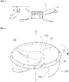
- FIG. 1 is a perspective view of an outdoor unit of an outdoor unit of an air conditioner, including an axial flow fan.
- FIG. 2 is a sectional view of FIG. 1 taken along line A-A
- FIG 3 is a perspective view of the axial flow fan illustrated in FIG. 2 .
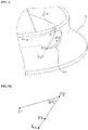
- FIG. 4 is an enlarged perspective view of a portion B in FIG. 3 .
- FIGS. 5A and 5B illustrate vectors in FIG. 4 .
- the outdoor unit 1 of an air conditioner may include a casing 2 that defines an exterior of an outdoor unit 1 of an air conditioner, and a motor (not shown) that provides rotational force and an axial flow fan 10 rotated by the motor may be provided within the casing 2.
- An inlet 3 may be defined at a side surface of the casing 2, and an opening may be defined at the front surface of the casing 2.
- a portion 20 of the casing 2 defines an outlet for discharging air blown by the axial fan 10.
- the casing portion 20 may be a portion 20 that is separately formed and then fastened to the opening defined at the front surface of the casing 2, or the casing portion 10 defining the outlet may be integrally formed with the front surface of the casing 2.
- the air blown by the axial flow fan 10 may be discharged to the outdoors through the outlet restricted by the casing portion 20.
- the casing portion 20 may be provided with a grill 4 for preventing the influx of foreign objects through the outlet.
- the axial flow fan 10 may be rotated by a driving member such as a motor (not shown), and for this end, may comprise a hub 11 for connecting to a driveshaft of the motor, a plurality of main wings 12 extending radially from the hub 11, and a rim 13 connecting each tip of the main wings 12 to one another and rotating integrally with the main wings 12.
- the main wings 12 extend radially from the periphery of the hub 11, and have a leading edge 12a at which airflow begins to rise, a trailing edge 12c at the opposite side of the leading edge 12a and a wing tip 12 between the leading edge 12a and the trailing edge 12c.
- tip leakage loss the loss of airflow at the tips of the axial flow fan 10 will be referred to as tip leakage loss.
- Representative causes of tip leakage loss include a vortex generated at the wing tips 12b of the main wings 12, and leakage flow that flows in from the outside between the wing tips 12b of the main wings 12 and the inner periphery of the casing portion 20.
- an axial flow fan 10 connects the wing tips 12b of each main wing 12 with a rim 13, to maintain the radial internal clearance between the rim 13 and the casing portion 20 uniformly.
- the inner diameter of the rim 13 progressively diminishes according to the flow path of air forced by the main wings 12. Therefore, the rim 13 performs the function of guiding the air moved by the main wings 12 to the outlet, and is formed so that the diameter of the inner periphery 13a contacting air moved by the main wings 12 becomes progressively smaller towards the outlet.
- the outer periphery 13b of the rim 13 may include a curved surface portion with a diameter that progressively lessens toward the outlet.
- the axial flow fan 10 further comprises one or more air entry blockers disposed at a clearance space between the rim and the portion of the casing defining the outlet or any means for reducing a backflow of outside air through a clearance space between the rotating rim and the portion of the casing defining the outlet.
- air entry blockers disposed at a clearance space between the rim and the portion of the casing defining the outlet or any means for reducing a backflow of outside air through a clearance space between the rotating rim and the portion of the casing defining the outlet.
- the auxiliary wings 14 rotate integrally with the rim 13 about the rotational axis (C), and a flow of air formed by the auxiliary wings 14 blocks an influx of air from the outside between the rim 13 and casing portion 20. Accordingly, the flow direction of air forcibly blown by the auxiliary wings 14 may have axial direction components.
- the auxiliary wings 14 may be configured as wings extending forward in the direction of rotation.
- P1 and P2 illustrated in FIGS. 4 and 5A are points indicated on a positive pressure surface of an auxiliary wing 14 on which a pressure greater than atmospheric pressure is applied when the axial flow fan 14 rotates.
- P1 is the outer end point of the auxiliary wing 14
- P2 is the inner end point of the auxiliary wing, so that P1 is positioned further forward in terms of the direction of rotation than P2. Therefore, an angle ⁇ 1 formed by a line L A connecting P1 and P2 and a tangent L T passing P2 and tangential to the outer periphery of the rim 13 is an acute angle.
- a certain normal line L N perpendicular to the positive pressure surface of the auxiliary wing 14 may be represented as the sum of a component Lz parallel to the rotational axis (C) and a directional component L R toward the central portion of the rim 13, and an angle ⁇ 2 formed by L N and L Z has a value of less than 90 degrees. Accordingly, air blown by the positive pressure surfaces of the auxiliary wings 14 generates an air curtain between the rim 13 and casing portion 20 to block entry of air from the outside.
- ⁇ 2 is an acute angle
- ⁇ 2 is an acute angle
- FIG. 6 illustrates a first example not covered by the claims.
- FIG. 7 is an enlarged view of portion B in FIG. 6 .
- a labyrinth seal is disposed between a casing portion 120 and a rim 130.
- corrugations 122 may be formed in at least one of the inner periphery of the casing portion and the outer periphery of the rim 130. While FIG. 6 depicts corrugations formed in the inner periphery of the casing portion 120, corrugations may alternately be formed on the outer periphery of the rim 130, or corrugations may be formed respectively on the inner periphery of the casing portion 120 and the outer periphery of the rim 130 to form labyrinth.
- the rim 130 connects the wing tips 12b of the main wings 12 to one another and comprises a curved portion 131 with an inner diameter that progressively decreases in the flow direction of air forcibly blown by the main wings 12, and a side surface portion 132 extending from the curved portion 131 parallel to the casing portion 120. While the labyrinth seal in FIG. 7 is configured of a labyrinth formed between corrugations 122 defined in the inner periphery of the casing portion 120 and the side surface portion 132 of the rim 130, corrugations may also be defined in the side surface portion 132 of the rim 130 to make the labyrinth even narrower.
- FIG. 8 illustrates the claimed embodiment.
- a baffle is formed on at least one of the inner periphery of a casing portion 220 and the outer periphery of a rim 230.
- the baffle denotes a device that restricts the flow of fluid in a certain path or redirects flow, and in this embodiment, a first baffle 224 may be formed extending in annular form along the inner periphery of the casing portion 220, and a second baffle 133 may be formed extending in annular form along the outer periphery of the curved portion 131 of the rim 230, in order to block air flowing thorough the radial internal clearance between the casing portion 220 and the rim 230.
- first baffle 224 and the second baffle 133 are respectively formed in plurality, with the second baffles 133 disposed between the first baffles 224. Also, in order to reduce noise generated when the rim 230 rotates at high speed, the second baffle 133 is formed at a lower height than the first baffle 224.
- the outdoor unit of an air conditioner block the influx of air between blade tips of an axial flow fan and outlet, so that the airflow blown by the axial flow fan may be increased. Also, the outdoor unit may reduce noise generated during rotation of the axial flow fan.
- the outdoor unit of an air conditioner may prevent inflow of outside air through a radial clearance between a rotating axial flow fan and a casing portion defining an outlet.
Landscapes
- Engineering & Computer Science (AREA)
- Mechanical Engineering (AREA)
- General Engineering & Computer Science (AREA)
- Chemical & Material Sciences (AREA)
- Combustion & Propulsion (AREA)
- Structures Of Non-Positive Displacement Pumps (AREA)
- Other Air-Conditioning Systems (AREA)
Description
- Exemplary embodiments of the present invention relate to an outdoor unit of an air conditioner, and more particularly, to an outdoor unit including an axial flow fan.
- In general, an air conditioner is an apparatus that provides users with a more pleasant indoor environment by cooling/heating an indoor space using a refrigeration cycle for refrigerant, constituted by a compressor, condenser, expansion unit, and an evaporator, or by filtering indoor air.
- Such a typical air conditioner comprises an indoor unit installed indoors to perform heat exchange between refrigerant and indoor air to discharge hot air or cold air into the indoor space, and an outdoor unit connected to the indoor unit through a refrigerant pipe to perform heat exchange between refrigerant and outdoor air.
- Here, in order to allow effective phase change of refrigerant in the outdoor unit, an axial flow fan is provided to blow air in the outdoor unit to the outside. A major limitation with blower units employing such axial flow fans is tip leakage loss, which reduces airflow and increases rotating noise.
-
JP 2002 106490 A -
JP 2002 106721 A - Further related technology is shown in
US 3 842 902 A orUS 2002/164247 A1 . - Accordingly, the present invention is directed to an outdoor unit of an air conditioner that substantially obviate one or more problems due to limitations and disadvantages of the related art.
- An advantage of the present invention is to provide a outdoor unit of an air conditioner that reduces noise.
- Another advantage of the present invention is to provide an outdoor unit of an air conditioner that increases airflow blown by an axial flow fan.
- Another advantage of the present invention is to provide an outdoor unit of an air conditioner that reduces occurrence of leakage flow at the wing tips of an axial flow fan.
- To achieve these and other advantages and in accordance with the purpose of the present invention, as embodied and broadly described, the invention provides an outdoor unit for an air conditioner as defined in
independent claim 1. - The rim may include a front edge, a rear edge, an inner surface and an outer surface, wherein the front edge is closer to the outlet than the rear edge, and wherein the one or more air entry blockers include a plurality of auxiliary wings, which are not covered by the scope of the claims, and are formed on the outer surface of the rim. The plurality of auxiliary wings may be disposed in the clearance space.
- Each auxiliary wing may have a leading edge at which air flow begins and a trailing edge opposite the leading edge. The leading edge may be positioned further forward towards the direction of rotation than the trailing edge, and the trailing edge may be positioned further forward towards the front of the rim than the leading edge.
- An outer radius of the front of the rim may be less than an outer radius of the back of the rim, and a distance between the leading edge of the auxiliary wing and the axis of the axial flow fan may be greater than a distance between the trailing edge of the auxiliary wing and the axis of the axial flow fan. The outer radius of the back of the rim may be greater than a distance between the axis of the axial flow fan and all portions of the auxiliary wings.
- The one or more baffles include: a plurality of first baffles on the casing portion and extending around the outlet; and a second baffle on and extending around the rim, wherein the second baffle is disposed between adjacent first baffles. The first baffles extend from the outlet a greater distance than the second baffle extends from the rim
- The outdoor unit may further comprise a grill over the outlet for preventing foreign objects entering the outlet.
- Each main wing may have a leading edge at which airflow begins, a trailing edge opposite the leading edge, and a wing tip between the leading edge and the trailing edge, wherein the rim connects a portion of the wing tips of the main wings to one another. A length of the leading edge may be shorter than a combined length of the wing tip and the trailing edge.
- It is to be understood that both the foregoing general description and the following detailed description are exemplary and explanatory and are intended to provide further explanation of the invention as claimed.
- The accompanying drawings, which are included to provide a further understanding of the invention and are incorporated in and constitute a part of this specification, illustrate embodiments of the invention and together with the description serve to explain the principles of the invention.
- In the drawings:
-
FIG. 1 is a perspective view of an outdoor unit of an air conditioner, including an axial flow fan; -
FIG. 2 is a sectional view ofFIG. 1 taken along line A-A, andFIG 3 is a perspective view of the axial flow fan illustrated inFIG. 2 ; -
FIG. 4 is an enlarged perspective view of a portion B inFIG. 3 ; -
FIGS. 5A and5B illustrate vectors inFIG. 4 ; -
FIG. 6 illustrates another an outdoor unit of an air conditioner, including an axial flow fan; -
FIG. 7 is an enlarged view of portion B inFIG. 6 ; and -
FIG. 8 is an enlarged view of a portion of another outdoor unit of an air conditioner. - Reference will now be made in detail to embodiments of the present invention, examples of which is illustrated in the accompanying drawings. This invention may, however, be embodied in many different forms and should not be construed as limited to the exemplary embodiments set forth herein. Rather, these exemplary embodiments are provided so that this disclosure is thorough, and will fully convey the scope of the invention to those skilled in the art. Wherever possible, the same reference numbers will be used throughout the drawings to refer to the same or like parts.
-
FIG. 1 is a perspective view of an outdoor unit of an outdoor unit of an air conditioner, including an axial flow fan.FIG. 2 is a sectional view ofFIG. 1 taken along line A-A, andFIG 3 is a perspective view of the axial flow fan illustrated inFIG. 2 .FIG. 4 is an enlarged perspective view of a portion B inFIG. 3 .FIGS. 5A and5B illustrate vectors inFIG. 4 . - Referring to
FIGS. 1 and2 , theoutdoor unit 1 of an air conditioner may include acasing 2 that defines an exterior of anoutdoor unit 1 of an air conditioner, and a motor (not shown) that provides rotational force and anaxial flow fan 10 rotated by the motor may be provided within thecasing 2. - An
inlet 3 may be defined at a side surface of thecasing 2, and an opening may be defined at the front surface of thecasing 2. Aportion 20 of thecasing 2 defines an outlet for discharging air blown by theaxial fan 10. Thecasing portion 20 may be aportion 20 that is separately formed and then fastened to the opening defined at the front surface of thecasing 2, or thecasing portion 10 defining the outlet may be integrally formed with the front surface of thecasing 2. - The air blown by the
axial flow fan 10 may be discharged to the outdoors through the outlet restricted by thecasing portion 20. Thecasing portion 20 may be provided with agrill 4 for preventing the influx of foreign objects through the outlet. - Referring to
FIG. 3 , theaxial flow fan 10 may be rotated by a driving member such as a motor (not shown), and for this end, may comprise ahub 11 for connecting to a driveshaft of the motor, a plurality ofmain wings 12 extending radially from thehub 11, and arim 13 connecting each tip of themain wings 12 to one another and rotating integrally with themain wings 12. Themain wings 12 extend radially from the periphery of thehub 11, and have a leadingedge 12a at which airflow begins to rise, atrailing edge 12c at the opposite side of the leadingedge 12a and awing tip 12 between the leadingedge 12a and thetrailing edge 12c. - Below, the loss of airflow at the tips of the
axial flow fan 10 will be referred to as tip leakage loss. Representative causes of tip leakage loss include a vortex generated at thewing tips 12b of themain wings 12, and leakage flow that flows in from the outside between thewing tips 12b of themain wings 12 and the inner periphery of thecasing portion 20. To reduce this tip leakage loss, anaxial flow fan 10 connects thewing tips 12b of eachmain wing 12 with arim 13, to maintain the radial internal clearance between therim 13 and thecasing portion 20 uniformly. - The inner diameter of the
rim 13 progressively diminishes according to the flow path of air forced by themain wings 12. Therefore, therim 13 performs the function of guiding the air moved by themain wings 12 to the outlet, and is formed so that the diameter of theinner periphery 13a contacting air moved by themain wings 12 becomes progressively smaller towards the outlet. Likewise, theouter periphery 13b of therim 13 may include a curved surface portion with a diameter that progressively lessens toward the outlet. - By means of the rotation of the
axial flow fan 10, most of the air from within theoutdoor unit 1 is discharged outward (that is, outdoors), and the effect of the vortex generated between therim 13 and the casing portion 20 - that is, as a result of frictional effects of air between each surface of therim 13 and casing portion 20 - a portion of air has a tendency to flow in the direction opposite to the discharged direction, between therim 13 andcasing portion 20 from the outdoors back into theoutdoor unit 1. Below, the flow of air that enters between therim 13 andcasing portion 20 will be defined as leakage flow, as it is a factor that reduces the airflow blown by theaxial flow fan 10. The greater the leakage flow, the less the blower performance of theaxial flow fan 10 is, and in addition to reducing airflow, leakage flow increases noise. - In order to prevent the occurrence of such leakage flow, the
axial flow fan 10 further comprises one or more air entry blockers disposed at a clearance space between the rim and the portion of the casing defining the outlet or any means for reducing a backflow of outside air through a clearance space between the rotating rim and the portion of the casing defining the outlet. Below, descriptions of various embodiments will be provided, and a plurality ofauxiliary wings 14 formed along the outer periphery of therim 13 as illustrated inFIGS. 2 to 5 will be described first. - When the
axial flow fan 10 rotates, forcibly blown air by themain wings 12 is discharged in the axial direction, and here, theauxiliary wings 14 rotate integrally with therim 13 about the rotational axis (C), and a flow of air formed by theauxiliary wings 14 blocks an influx of air from the outside between therim 13 andcasing portion 20. Accordingly, the flow direction of air forcibly blown by theauxiliary wings 14 may have axial direction components. - Like the
main wings 12, theauxiliary wings 14 may be configured as wings extending forward in the direction of rotation. P1 and P2 illustrated inFIGS. 4 and 5A are points indicated on a positive pressure surface of anauxiliary wing 14 on which a pressure greater than atmospheric pressure is applied when theaxial flow fan 14 rotates. P1 is the outer end point of theauxiliary wing 14, and P2 is the inner end point of the auxiliary wing, so that P1 is positioned further forward in terms of the direction of rotation than P2. Therefore, an angle Θ1 formed by a line LA connecting P1 and P2 and a tangent LT passing P2 and tangential to the outer periphery of therim 13 is an acute angle. - Referring to
FIGS. 4 and5B , a certain normal line LN perpendicular to the positive pressure surface of theauxiliary wing 14 may be represented as the sum of a component Lz parallel to the rotational axis (C) and a directional component LR toward the central portion of therim 13, and an angle Θ2 formed by LN and LZ has a value of less than 90 degrees. Accordingly, air blown by the positive pressure surfaces of theauxiliary wings 14 generates an air curtain between therim 13 andcasing portion 20 to block entry of air from the outside. - Particularly, when Θ2 is an acute angle, because airflow is discharged by the
auxiliary wings 14 between therim 13 andcasing portion 20 to the outside, it adds to the airflow discharged by themain wings 11 to increase total airflow. -
FIG. 6 illustrates a first example not covered by the claims.FIG. 7 is an enlarged view of portion B inFIG. 6 . Referring toFIGS. 6 and7 , a labyrinth seal is disposed between acasing portion 120 and arim 130. - To form a labyrinth seal,
corrugations 122 may be formed in at least one of the inner periphery of the casing portion and the outer periphery of therim 130. WhileFIG. 6 depicts corrugations formed in the inner periphery of thecasing portion 120, corrugations may alternately be formed on the outer periphery of therim 130, or corrugations may be formed respectively on the inner periphery of thecasing portion 120 and the outer periphery of therim 130 to form labyrinth. - The
rim 130 connects thewing tips 12b of themain wings 12 to one another and comprises acurved portion 131 with an inner diameter that progressively decreases in the flow direction of air forcibly blown by themain wings 12, and aside surface portion 132 extending from thecurved portion 131 parallel to thecasing portion 120. While the labyrinth seal inFIG. 7 is configured of a labyrinth formed betweencorrugations 122 defined in the inner periphery of thecasing portion 120 and theside surface portion 132 of therim 130, corrugations may also be defined in theside surface portion 132 of therim 130 to make the labyrinth even narrower. -
FIG. 8 illustrates the claimed embodiment. Referring toFIG. 8 , a baffle is formed on at least one of the inner periphery of acasing portion 220 and the outer periphery of arim 230. The baffle denotes a device that restricts the flow of fluid in a certain path or redirects flow, and in this embodiment, afirst baffle 224 may be formed extending in annular form along the inner periphery of thecasing portion 220, and asecond baffle 133 may be formed extending in annular form along the outer periphery of thecurved portion 131 of therim 230, in order to block air flowing thorough the radial internal clearance between thecasing portion 220 and therim 230. - Here, the
first baffle 224 and thesecond baffle 133 are respectively formed in plurality, with thesecond baffles 133 disposed between thefirst baffles 224. Also, in order to reduce noise generated when therim 230 rotates at high speed, thesecond baffle 133 is formed at a lower height than thefirst baffle 224. - The outdoor unit of an air conditioner according to embodiments of the present invention block the influx of air between blade tips of an axial flow fan and outlet, so that the airflow blown by the axial flow fan may be increased. Also, the outdoor unit may reduce noise generated during rotation of the axial flow fan.
- Also, the outdoor unit of an air conditioner may prevent inflow of outside air through a radial clearance between a rotating axial flow fan and a casing portion defining an outlet.
Claims (5)
- An outdoor unit for an air conditioner, comprising:a casing (2), including a portion (220) defining an outlet through which air is discharged from the outdoor unit;an axial flow fan (10) disposed in the casing for blowing air through the outlet, wherein the axial flow fan (10) comprises:a hub (11);a plurality of main wings (12) extending from the hub (11); anda rim (230) connecting the main wings (12) to one other and rotating integrally with the main wings (12); andone or more air entry blockers disposed at a clearance space between the rim (230) and the portion (220) of the casing defining the outlet,wherein the one or more air entry blockers include baffles (224,133) which restrict the flow of fluid in a certain path or redirect flow and are formed on at least one of the rim (230) and the portion (220) of the casing,wherein the rim (230) comprises a curved portion (131) with an inner diameter that progressively decreases in the flow direction of air forcibly blown by the main wings (12),characterised in that the baffles include:a plurality of first baffles (224) on the casing portion and extending around the outlet; anda plurality of second baffles (133) on and extending around the rim (230), wherein the second baffles (133) are disposed between adjacent first baffles (224);the second baffles (133) are formed at a lower height than the first baffles (224).
- The outdoor unit of claim 1, wherein the first baffle (224) extends from the outlet a greater distance than the second baffle (130) extends from the rim (230).
- The outdoor unit of claim 1, wherein a first baffle (224) is formed extending in annular form along the inner periphery of the casing portion (220), and a second baffle is formed extending in annular form along the outer periphery of the curved portion (131) of the rim (230).
- The outdoor unit of claim 1, further comprising a grill over the outlet for preventing foreign objects entering the outlet.
- The outdoor unit of claim 1, wherein each main wing (12) has a leading edge (12a) at which airflow begins, a trailing edge (12c) opposite the leading edge (12a), and a wing tip between the leading edge (12a) and the trailing edge (12c), wherein the rim connects a portion of the wing tips of the main wings (12) to one another.
Applications Claiming Priority (2)
| Application Number | Priority Date | Filing Date | Title |
|---|---|---|---|
| KR1020100105396A KR101724294B1 (en) | 2010-10-27 | 2010-10-27 | Out door unit of air conditioner |
| EP11186498.9A EP2447542B1 (en) | 2010-10-27 | 2011-10-25 | Air conditioner with outdoor unit |
Related Parent Applications (2)
| Application Number | Title | Priority Date | Filing Date |
|---|---|---|---|
| EP11186498.9A Division-Into EP2447542B1 (en) | 2010-10-27 | 2011-10-25 | Air conditioner with outdoor unit |
| EP11186498.9A Division EP2447542B1 (en) | 2010-10-27 | 2011-10-25 | Air conditioner with outdoor unit |
Publications (2)
| Publication Number | Publication Date |
|---|---|
| EP3626974A1 EP3626974A1 (en) | 2020-03-25 |
| EP3626974B1 true EP3626974B1 (en) | 2023-01-25 |
Family
ID=44862676
Family Applications (2)
| Application Number | Title | Priority Date | Filing Date |
|---|---|---|---|
| EP19200968.6A Active EP3626974B1 (en) | 2010-10-27 | 2011-10-25 | Outdoor unit for an air conditioner |
| EP11186498.9A Active EP2447542B1 (en) | 2010-10-27 | 2011-10-25 | Air conditioner with outdoor unit |
Family Applications After (1)
| Application Number | Title | Priority Date | Filing Date |
|---|---|---|---|
| EP11186498.9A Active EP2447542B1 (en) | 2010-10-27 | 2011-10-25 | Air conditioner with outdoor unit |
Country Status (4)
| Country | Link |
|---|---|
| US (1) | US9228591B2 (en) |
| EP (2) | EP3626974B1 (en) |
| KR (1) | KR101724294B1 (en) |
| CN (1) | CN102454642B (en) |
Families Citing this family (13)
| Publication number | Priority date | Publication date | Assignee | Title |
|---|---|---|---|---|
| US9885368B2 (en) | 2012-05-24 | 2018-02-06 | Carrier Corporation | Stall margin enhancement of axial fan with rotating shroud |
| EP2943689B1 (en) | 2013-01-11 | 2019-06-26 | Carrier Corporation | Shrouded axial fan with casing treatment |
| CN203453120U (en) * | 2013-09-03 | 2014-02-26 | 讯凯国际股份有限公司 | Fan and fan impeller thereof |
| ITTO20130806A1 (en) * | 2013-10-04 | 2015-04-05 | Johnson Electric Asti S R L | VENTILATION GROUP, PARTICULARLY FOR A HEAT EXCHANGER OF A MOTOR VEHICLE |
| CN103982466B (en) * | 2014-04-23 | 2017-02-22 | 镇江市博林光电科技有限公司 | Large-suction-force axial flow fan |
| USD779049S1 (en) * | 2015-06-09 | 2017-02-14 | Youngo Limited | Ceiling fan |
| US10557638B2 (en) | 2017-11-21 | 2020-02-11 | Haier Us Appliance Solutions, Inc. | Fan assembly for a packaged terminal air conditioner unit |
| JP1607894S (en) * | 2017-11-24 | 2018-07-02 | ||
| CN107940577B (en) * | 2017-12-18 | 2023-09-12 | 广东美的制冷设备有限公司 | Centrifugal wind wheel, air inlet assembly and ceiling machine |
| US11142038B2 (en) | 2017-12-18 | 2021-10-12 | Carrier Corporation | Labyrinth seal for fan assembly |
| US10962275B2 (en) * | 2018-01-25 | 2021-03-30 | Johnson Controls Technology Company | Condenser unit with fan |
| US10982863B2 (en) * | 2018-04-10 | 2021-04-20 | Carrier Corporation | HVAC fan inlet |
| US11022140B2 (en) * | 2018-09-04 | 2021-06-01 | Johnson Controls Technology Company | Fan blade winglet |
Family Cites Families (31)
| Publication number | Priority date | Publication date | Assignee | Title |
|---|---|---|---|---|
| US3189982A (en) * | 1961-10-03 | 1965-06-22 | Torrington Mfg Co | Method of making integral fan and slinger ring |
| FR1502832A (en) * | 1966-09-26 | 1967-11-24 | Nord Aviation | Diffusion faired propeller |
| US3842902A (en) * | 1973-07-05 | 1974-10-22 | Hayes Albion Corp | Labyrinthian fan |
| US5489186A (en) | 1991-08-30 | 1996-02-06 | Airflow Research And Manufacturing Corp. | Housing with recirculation control for use with banded axial-flow fans |
| US5183382A (en) * | 1991-09-03 | 1993-02-02 | Caterpillar Inc. | Low noise rotating fan and shroud assembly |
| US5437541A (en) * | 1993-12-30 | 1995-08-01 | Vainrub; John | Blade for axial fan |
| KR100467331B1 (en) * | 1997-06-05 | 2005-04-08 | 한라공조주식회사 | Fan and fan-shroud assembly |
| JP4481414B2 (en) * | 2000-03-03 | 2010-06-16 | 株式会社ティラド | Fan seal structure |
| JP2001248736A (en) | 2000-03-03 | 2001-09-14 | Toyo Radiator Co Ltd | Labyrinth seal structure of fan |
| DE60143977D1 (en) * | 2000-07-04 | 2011-03-10 | Sharp Kk | Propeller fan, mold for shaping a propeller fan and fluid supply device |
| JP4592908B2 (en) * | 2000-09-28 | 2010-12-08 | 株式会社ティラド | Fan seal structure |
| JP2002106721A (en) | 2000-09-29 | 2002-04-10 | Toyo Radiator Co Ltd | Labylinth seal structure |
| US6508624B2 (en) * | 2001-05-02 | 2003-01-21 | Siemens Automotive, Inc. | Turbomachine with double-faced rotor-shroud seal structure |
| KR100729650B1 (en) | 2002-02-27 | 2007-06-18 | 한라공조주식회사 | Shroud having structure for noise reduction |
| JP4456821B2 (en) * | 2002-10-04 | 2010-04-28 | 株式会社ティラド | Fan with ring and method for manufacturing the same |
| US6866474B2 (en) * | 2003-01-27 | 2005-03-15 | Lennox Industries, Inc. | Noise reduction by vortex suppression in air flow systems |
| US6874990B2 (en) | 2003-01-29 | 2005-04-05 | Siemens Vdo Automotive Inc. | Integral tip seal in a fan-shroud structure |
| KR100511991B1 (en) * | 2003-07-23 | 2005-09-02 | 엘지전자 주식회사 | A blower fan structure of an air conditioner |
| USD511824S1 (en) * | 2004-01-19 | 2005-11-22 | Delta Electronics, Inc. | Fan |
| US7086825B2 (en) * | 2004-09-24 | 2006-08-08 | Carrier Corporation | Fan |
| US7484925B2 (en) * | 2005-05-10 | 2009-02-03 | Emp Advanced Development, Llc | Rotary axial fan assembly |
| EP2029897B1 (en) * | 2006-05-31 | 2010-10-06 | Robert Bosch GmbH | Axial fan assembly |
| US7789622B2 (en) * | 2006-09-26 | 2010-09-07 | Delphi Technologies, Inc. | Engine cooling fan assembly |
| DE102006047236B4 (en) * | 2006-10-04 | 2017-06-29 | Mahle International Gmbh | Axial fan arranged to promote cooling air of a cooling device of a motor vehicle |
| CN101668678B (en) * | 2006-12-28 | 2012-02-08 | 开利公司 | Axial fan device and its manufacture method |
| ES2702364T3 (en) * | 2008-04-22 | 2019-02-28 | Mitsubishi Electric Corp | Blower and heat pump device that uses the same |
| US8317478B2 (en) * | 2008-10-08 | 2012-11-27 | Nidec Servo Corporation | Impeller, fan apparatus using the same, and method of manufacturing impeller |
| DE102009012025A1 (en) * | 2009-03-10 | 2010-09-16 | Behr Gmbh & Co. Kg | Cooling device for a motor vehicle |
| CN201475009U (en) | 2009-08-03 | 2010-05-19 | 合肥通用机械研究院 | Axial-flow fan with anti-resonance and noise-reduction rib plates on casing thereof for air conditioner |
| KR20100091136A (en) * | 2010-07-05 | 2010-08-18 | 엘지전자 주식회사 | Front suction and discharge type outdoor unit for air-conditioner |
| KR20120080789A (en) * | 2011-01-10 | 2012-07-18 | 엘지전자 주식회사 | Outdoor unit for air conditioner |
-
2010
- 2010-10-27 KR KR1020100105396A patent/KR101724294B1/en active IP Right Grant
-
2011
- 2011-10-06 US US13/267,520 patent/US9228591B2/en active Active
- 2011-10-25 EP EP19200968.6A patent/EP3626974B1/en active Active
- 2011-10-25 EP EP11186498.9A patent/EP2447542B1/en active Active
- 2011-10-27 CN CN201110343232.3A patent/CN102454642B/en not_active Expired - Fee Related
Also Published As
| Publication number | Publication date |
|---|---|
| EP2447542A3 (en) | 2018-03-07 |
| CN102454642A (en) | 2012-05-16 |
| EP2447542A2 (en) | 2012-05-02 |
| KR20120044033A (en) | 2012-05-07 |
| US9228591B2 (en) | 2016-01-05 |
| EP2447542B1 (en) | 2019-12-04 |
| CN102454642B (en) | 2014-12-17 |
| KR101724294B1 (en) | 2017-04-07 |
| US20120108161A1 (en) | 2012-05-03 |
| EP3626974A1 (en) | 2020-03-25 |
Similar Documents
| Publication | Publication Date | Title |
|---|---|---|
| EP3626974B1 (en) | Outdoor unit for an air conditioner | |
| JP5263198B2 (en) | Impeller, blower and air conditioner using the same | |
| JP6225332B2 (en) | Blower and outdoor unit equipped with the blower | |
| CN110325745B (en) | Propeller fan, blower, and air conditioner | |
| JP5971667B2 (en) | Propeller fan, blower and outdoor unit | |
| JP6377172B2 (en) | Outdoor unit for propeller fan, propeller fan device and air conditioner | |
| WO2017026143A1 (en) | Blower and air-conditioning device | |
| JP6945739B2 (en) | Multi-blade blower and air conditioner | |
| JP2004218450A (en) | Centrifugal blower | |
| JP6035508B2 (en) | Blower and outdoor unit using it | |
| JP6811866B2 (en) | Propeller fan, blower, and refrigeration cycle device | |
| JP6224952B2 (en) | Blower | |
| JP2011179331A (en) | Blower, and air conditioner using the same | |
| JP7378611B2 (en) | Axial fans, blowers, and refrigeration cycle equipment | |
| JP2006220106A (en) | Centrifugal blower and air conditioner having centrifugal blower | |
| CN110914550B (en) | Indoor unit of air conditioner | |
| WO2015064617A1 (en) | Cross-flow fan and air conditioner | |
| JP2005016457A (en) | Blower and heat exchange unit equipped with blower | |
| WO2023084652A1 (en) | Cross-flow fan, blowing device, and refrigeration cycle device | |
| US20220325905A1 (en) | Air handling unit and fan therefor | |
| WO2023223383A1 (en) | Cross flow fan, blowing device, and refrigeration cycle device | |
| WO2024009466A1 (en) | Axial fan, blower, outdoor unit, and air conditioner | |
| WO2022091225A1 (en) | Axial-flow fan, blowing device, and refrigeration cycle device | |
| KR20120076047A (en) | Outdoor unit for air conditioner | |
| JPWO2018127953A1 (en) | Propeller fan and outdoor unit of air conditioner |
Legal Events
| Date | Code | Title | Description |
|---|---|---|---|
| PUAI | Public reference made under article 153(3) epc to a published international application that has entered the european phase |
Free format text: ORIGINAL CODE: 0009012 |
|
| STAA | Information on the status of an ep patent application or granted ep patent |
Free format text: STATUS: REQUEST FOR EXAMINATION WAS MADE |
|
| 17P | Request for examination filed |
Effective date: 20191102 |
|
| AC | Divisional application: reference to earlier application |
Ref document number: 2447542 Country of ref document: EP Kind code of ref document: P |
|
| AK | Designated contracting states |
Kind code of ref document: A1 Designated state(s): AL AT BE BG CH CY CZ DE DK EE ES FI FR GB GR HR HU IE IS IT LI LT LU LV MC MK MT NL NO PL PT RO RS SE SI SK SM TR |
|
| RBV | Designated contracting states (corrected) |
Designated state(s): AL AT BE BG CH CY CZ DE DK EE ES FI FR GB GR HR HU IE IS IT LI LT LU LV MC MK MT NL NO PL PT RO RS SE SI SK SM TR |
|
| STAA | Information on the status of an ep patent application or granted ep patent |
Free format text: STATUS: EXAMINATION IS IN PROGRESS |
|
| STAA | Information on the status of an ep patent application or granted ep patent |
Free format text: STATUS: EXAMINATION IS IN PROGRESS |
|
| 17Q | First examination report despatched |
Effective date: 20201211 |
|
| GRAP | Despatch of communication of intention to grant a patent |
Free format text: ORIGINAL CODE: EPIDOSNIGR1 |
|
| STAA | Information on the status of an ep patent application or granted ep patent |
Free format text: STATUS: GRANT OF PATENT IS INTENDED |
|
| INTG | Intention to grant announced |
Effective date: 20220909 |
|
| RIN1 | Information on inventor provided before grant (corrected) |
Inventor name: MOON, DONGSOO Inventor name: CHOI, SEOKHO |
|
| GRAS | Grant fee paid |
Free format text: ORIGINAL CODE: EPIDOSNIGR3 |
|
| GRAA | (expected) grant |
Free format text: ORIGINAL CODE: 0009210 |
|
| STAA | Information on the status of an ep patent application or granted ep patent |
Free format text: STATUS: THE PATENT HAS BEEN GRANTED |
|
| AC | Divisional application: reference to earlier application |
Ref document number: 2447542 Country of ref document: EP Kind code of ref document: P |
|
| AK | Designated contracting states |
Kind code of ref document: B1 Designated state(s): AL AT BE BG CH CY CZ DE DK EE ES FI FR GB GR HR HU IE IS IT LI LT LU LV MC MK MT NL NO PL PT RO RS SE SI SK SM TR |
|
| REG | Reference to a national code |
Ref country code: GB Ref legal event code: FG4D |
|
| REG | Reference to a national code |
Ref country code: CH Ref legal event code: EP |
|
| REG | Reference to a national code |
Ref country code: DE Ref legal event code: R096 Ref document number: 602011073639 Country of ref document: DE |
|
| REG | Reference to a national code |
Ref country code: AT Ref legal event code: REF Ref document number: 1546092 Country of ref document: AT Kind code of ref document: T Effective date: 20230215 Ref country code: IE Ref legal event code: FG4D |
|
| REG | Reference to a national code |
Ref country code: LT Ref legal event code: MG9D |
|
| REG | Reference to a national code |
Ref country code: NL Ref legal event code: MP Effective date: 20230125 |
|
| REG | Reference to a national code |
Ref country code: AT Ref legal event code: MK05 Ref document number: 1546092 Country of ref document: AT Kind code of ref document: T Effective date: 20230125 |
|
| PG25 | Lapsed in a contracting state [announced via postgrant information from national office to epo] |
Ref country code: NL Free format text: LAPSE BECAUSE OF FAILURE TO SUBMIT A TRANSLATION OF THE DESCRIPTION OR TO PAY THE FEE WITHIN THE PRESCRIBED TIME-LIMIT Effective date: 20230125 |
|
| PG25 | Lapsed in a contracting state [announced via postgrant information from national office to epo] |
Ref country code: RS Free format text: LAPSE BECAUSE OF FAILURE TO SUBMIT A TRANSLATION OF THE DESCRIPTION OR TO PAY THE FEE WITHIN THE PRESCRIBED TIME-LIMIT Effective date: 20230125 Ref country code: PT Free format text: LAPSE BECAUSE OF FAILURE TO SUBMIT A TRANSLATION OF THE DESCRIPTION OR TO PAY THE FEE WITHIN THE PRESCRIBED TIME-LIMIT Effective date: 20230525 Ref country code: NO Free format text: LAPSE BECAUSE OF FAILURE TO SUBMIT A TRANSLATION OF THE DESCRIPTION OR TO PAY THE FEE WITHIN THE PRESCRIBED TIME-LIMIT Effective date: 20230425 Ref country code: LV Free format text: LAPSE BECAUSE OF FAILURE TO SUBMIT A TRANSLATION OF THE DESCRIPTION OR TO PAY THE FEE WITHIN THE PRESCRIBED TIME-LIMIT Effective date: 20230125 Ref country code: LT Free format text: LAPSE BECAUSE OF FAILURE TO SUBMIT A TRANSLATION OF THE DESCRIPTION OR TO PAY THE FEE WITHIN THE PRESCRIBED TIME-LIMIT Effective date: 20230125 Ref country code: HR Free format text: LAPSE BECAUSE OF FAILURE TO SUBMIT A TRANSLATION OF THE DESCRIPTION OR TO PAY THE FEE WITHIN THE PRESCRIBED TIME-LIMIT Effective date: 20230125 Ref country code: ES Free format text: LAPSE BECAUSE OF FAILURE TO SUBMIT A TRANSLATION OF THE DESCRIPTION OR TO PAY THE FEE WITHIN THE PRESCRIBED TIME-LIMIT Effective date: 20230125 Ref country code: AT Free format text: LAPSE BECAUSE OF FAILURE TO SUBMIT A TRANSLATION OF THE DESCRIPTION OR TO PAY THE FEE WITHIN THE PRESCRIBED TIME-LIMIT Effective date: 20230125 |
|
| PG25 | Lapsed in a contracting state [announced via postgrant information from national office to epo] |
Ref country code: SE Free format text: LAPSE BECAUSE OF FAILURE TO SUBMIT A TRANSLATION OF THE DESCRIPTION OR TO PAY THE FEE WITHIN THE PRESCRIBED TIME-LIMIT Effective date: 20230125 Ref country code: PL Free format text: LAPSE BECAUSE OF FAILURE TO SUBMIT A TRANSLATION OF THE DESCRIPTION OR TO PAY THE FEE WITHIN THE PRESCRIBED TIME-LIMIT Effective date: 20230125 Ref country code: IS Free format text: LAPSE BECAUSE OF FAILURE TO SUBMIT A TRANSLATION OF THE DESCRIPTION OR TO PAY THE FEE WITHIN THE PRESCRIBED TIME-LIMIT Effective date: 20230525 Ref country code: GR Free format text: LAPSE BECAUSE OF FAILURE TO SUBMIT A TRANSLATION OF THE DESCRIPTION OR TO PAY THE FEE WITHIN THE PRESCRIBED TIME-LIMIT Effective date: 20230426 Ref country code: FI Free format text: LAPSE BECAUSE OF FAILURE TO SUBMIT A TRANSLATION OF THE DESCRIPTION OR TO PAY THE FEE WITHIN THE PRESCRIBED TIME-LIMIT Effective date: 20230125 |
|
| REG | Reference to a national code |
Ref country code: DE Ref legal event code: R097 Ref document number: 602011073639 Country of ref document: DE |
|
| PG25 | Lapsed in a contracting state [announced via postgrant information from national office to epo] |
Ref country code: SM Free format text: LAPSE BECAUSE OF FAILURE TO SUBMIT A TRANSLATION OF THE DESCRIPTION OR TO PAY THE FEE WITHIN THE PRESCRIBED TIME-LIMIT Effective date: 20230125 Ref country code: RO Free format text: LAPSE BECAUSE OF FAILURE TO SUBMIT A TRANSLATION OF THE DESCRIPTION OR TO PAY THE FEE WITHIN THE PRESCRIBED TIME-LIMIT Effective date: 20230125 Ref country code: EE Free format text: LAPSE BECAUSE OF FAILURE TO SUBMIT A TRANSLATION OF THE DESCRIPTION OR TO PAY THE FEE WITHIN THE PRESCRIBED TIME-LIMIT Effective date: 20230125 Ref country code: DK Free format text: LAPSE BECAUSE OF FAILURE TO SUBMIT A TRANSLATION OF THE DESCRIPTION OR TO PAY THE FEE WITHIN THE PRESCRIBED TIME-LIMIT Effective date: 20230125 Ref country code: CZ Free format text: LAPSE BECAUSE OF FAILURE TO SUBMIT A TRANSLATION OF THE DESCRIPTION OR TO PAY THE FEE WITHIN THE PRESCRIBED TIME-LIMIT Effective date: 20230125 |
|
| PGFP | Annual fee paid to national office [announced via postgrant information from national office to epo] |
Ref country code: IT Payment date: 20230906 Year of fee payment: 13 |
|
| PG25 | Lapsed in a contracting state [announced via postgrant information from national office to epo] |
Ref country code: SK Free format text: LAPSE BECAUSE OF FAILURE TO SUBMIT A TRANSLATION OF THE DESCRIPTION OR TO PAY THE FEE WITHIN THE PRESCRIBED TIME-LIMIT Effective date: 20230125 |
|
| PLBE | No opposition filed within time limit |
Free format text: ORIGINAL CODE: 0009261 |
|
| STAA | Information on the status of an ep patent application or granted ep patent |
Free format text: STATUS: NO OPPOSITION FILED WITHIN TIME LIMIT |
|
| 26N | No opposition filed |
Effective date: 20231026 |
|
| PG25 | Lapsed in a contracting state [announced via postgrant information from national office to epo] |
Ref country code: SI Free format text: LAPSE BECAUSE OF FAILURE TO SUBMIT A TRANSLATION OF THE DESCRIPTION OR TO PAY THE FEE WITHIN THE PRESCRIBED TIME-LIMIT Effective date: 20230125 |
|
| PGFP | Annual fee paid to national office [announced via postgrant information from national office to epo] |
Ref country code: DE Payment date: 20230905 Year of fee payment: 13 |