EP3623638B1 - Propeller fan - Google Patents
Propeller fan Download PDFInfo
- Publication number
- EP3623638B1 EP3623638B1 EP18820896.1A EP18820896A EP3623638B1 EP 3623638 B1 EP3623638 B1 EP 3623638B1 EP 18820896 A EP18820896 A EP 18820896A EP 3623638 B1 EP3623638 B1 EP 3623638B1
- Authority
- EP
- European Patent Office
- Prior art keywords
- blades
- propeller fan
- blade
- leading edge
- center axis
- Prior art date
- Legal status (The legal status is an assumption and is not a legal conclusion. Google has not performed a legal analysis and makes no representation as to the accuracy of the status listed.)
- Active
Links
- 239000011295 pitch Substances 0.000 claims description 44
- 230000005484 gravity Effects 0.000 claims description 13
- 238000007664 blowing Methods 0.000 description 8
- 230000000052 comparative effect Effects 0.000 description 6
- 238000005259 measurement Methods 0.000 description 3
- 230000007423 decrease Effects 0.000 description 2
- 239000000463 material Substances 0.000 description 2
- 230000009286 beneficial effect Effects 0.000 description 1
- 230000000737 periodic effect Effects 0.000 description 1
- 230000002093 peripheral effect Effects 0.000 description 1
- 239000011347 resin Substances 0.000 description 1
- 229920005989 resin Polymers 0.000 description 1
Images


Classifications
-
- F—MECHANICAL ENGINEERING; LIGHTING; HEATING; WEAPONS; BLASTING
- F04—POSITIVE - DISPLACEMENT MACHINES FOR LIQUIDS; PUMPS FOR LIQUIDS OR ELASTIC FLUIDS
- F04D—NON-POSITIVE-DISPLACEMENT PUMPS
- F04D29/00—Details, component parts, or accessories
- F04D29/26—Rotors specially for elastic fluids
- F04D29/32—Rotors specially for elastic fluids for axial flow pumps
- F04D29/325—Rotors specially for elastic fluids for axial flow pumps for axial flow fans
- F04D29/327—Rotors specially for elastic fluids for axial flow pumps for axial flow fans with non identical blades
-
- F—MECHANICAL ENGINEERING; LIGHTING; HEATING; WEAPONS; BLASTING
- F04—POSITIVE - DISPLACEMENT MACHINES FOR LIQUIDS; PUMPS FOR LIQUIDS OR ELASTIC FLUIDS
- F04D—NON-POSITIVE-DISPLACEMENT PUMPS
- F04D29/00—Details, component parts, or accessories
- F04D29/26—Rotors specially for elastic fluids
- F04D29/32—Rotors specially for elastic fluids for axial flow pumps
- F04D29/325—Rotors specially for elastic fluids for axial flow pumps for axial flow fans
- F04D29/328—Rotors specially for elastic fluids for axial flow pumps for axial flow fans with unequal distribution of blades around the hub
-
- F—MECHANICAL ENGINEERING; LIGHTING; HEATING; WEAPONS; BLASTING
- F04—POSITIVE - DISPLACEMENT MACHINES FOR LIQUIDS; PUMPS FOR LIQUIDS OR ELASTIC FLUIDS
- F04D—NON-POSITIVE-DISPLACEMENT PUMPS
- F04D29/00—Details, component parts, or accessories
- F04D29/26—Rotors specially for elastic fluids
- F04D29/32—Rotors specially for elastic fluids for axial flow pumps
- F04D29/38—Blades
- F04D29/384—Blades characterised by form
-
- F—MECHANICAL ENGINEERING; LIGHTING; HEATING; WEAPONS; BLASTING
- F04—POSITIVE - DISPLACEMENT MACHINES FOR LIQUIDS; PUMPS FOR LIQUIDS OR ELASTIC FLUIDS
- F04D—NON-POSITIVE-DISPLACEMENT PUMPS
- F04D29/00—Details, component parts, or accessories
- F04D29/66—Combating cavitation, whirls, noise, vibration or the like; Balancing
- F04D29/661—Combating cavitation, whirls, noise, vibration or the like; Balancing especially adapted for elastic fluid pumps
- F04D29/662—Balancing of rotors
-
- F—MECHANICAL ENGINEERING; LIGHTING; HEATING; WEAPONS; BLASTING
- F04—POSITIVE - DISPLACEMENT MACHINES FOR LIQUIDS; PUMPS FOR LIQUIDS OR ELASTIC FLUIDS
- F04D—NON-POSITIVE-DISPLACEMENT PUMPS
- F04D29/00—Details, component parts, or accessories
- F04D29/66—Combating cavitation, whirls, noise, vibration or the like; Balancing
- F04D29/661—Combating cavitation, whirls, noise, vibration or the like; Balancing especially adapted for elastic fluid pumps
- F04D29/666—Combating cavitation, whirls, noise, vibration or the like; Balancing especially adapted for elastic fluid pumps by means of rotor construction or layout, e.g. unequal distribution of blades or vanes
-
- F—MECHANICAL ENGINEERING; LIGHTING; HEATING; WEAPONS; BLASTING
- F05—INDEXING SCHEMES RELATING TO ENGINES OR PUMPS IN VARIOUS SUBCLASSES OF CLASSES F01-F04
- F05B—INDEXING SCHEME RELATING TO WIND, SPRING, WEIGHT, INERTIA OR LIKE MOTORS, TO MACHINES OR ENGINES FOR LIQUIDS COVERED BY SUBCLASSES F03B, F03D AND F03G
- F05B2240/00—Components
- F05B2240/20—Rotors
- F05B2240/30—Characteristics of rotor blades, i.e. of any element transforming dynamic fluid energy to or from rotational energy and being attached to a rotor
- F05B2240/301—Cross-section characteristics
-
- F—MECHANICAL ENGINEERING; LIGHTING; HEATING; WEAPONS; BLASTING
- F05—INDEXING SCHEMES RELATING TO ENGINES OR PUMPS IN VARIOUS SUBCLASSES OF CLASSES F01-F04
- F05B—INDEXING SCHEME RELATING TO WIND, SPRING, WEIGHT, INERTIA OR LIKE MOTORS, TO MACHINES OR ENGINES FOR LIQUIDS COVERED BY SUBCLASSES F03B, F03D AND F03G
- F05B2260/00—Function
- F05B2260/96—Preventing, counteracting or reducing vibration or noise
-
- F—MECHANICAL ENGINEERING; LIGHTING; HEATING; WEAPONS; BLASTING
- F05—INDEXING SCHEMES RELATING TO ENGINES OR PUMPS IN VARIOUS SUBCLASSES OF CLASSES F01-F04
- F05D—INDEXING SCHEME FOR ASPECTS RELATING TO NON-POSITIVE-DISPLACEMENT MACHINES OR ENGINES, GAS-TURBINES OR JET-PROPULSION PLANTS
- F05D2240/00—Components
- F05D2240/20—Rotors
- F05D2240/30—Characteristics of rotor blades, i.e. of any element transforming dynamic fluid energy to or from rotational energy and being attached to a rotor
- F05D2240/301—Cross-sectional characteristics
Definitions
- the present invention relates to a propeller fan for use in a blower or any other device.
- a propeller fan has been widely used for a blower or any other device.
- Noise generated through rotation of the propeller fan includes periodic noise called NZ noise.
- the frequency of the NZ noise is the product of the number of blades of the propeller fan and the rotational speed of the propeller fan.
- JP H05 233093 A shows that to reduce the discomfort of a user or any other person resulting from such NZ noise, blades are arranged at unequal pitches in the circumferential direction of a propeller fan.
- the propeller fan is rotationally unbalanced. Specifically, the center of gravity of the propeller fan and the rotational center axis of the propeller fan are apart from each other. In this state, if the rotationally unbalanced propeller fan is rotated, such rotational unbalance may cause the propeller fan to vibrate.
- JP H05 233093 A four blades having different leading edge shapes (and thus having different masses) are arranged at unequal pitches in the circumferential direction of the propeller fan to reduce the degree to which the propeller fan is rotationally unbalanced.
- JP H10 176 694 A discloses a fan capable of effectively suppressing the generation of noise consisting of a high level pure tone, wherein at least one of a plurality of adjacent blades formed in a fan having a plurality of blades is spaced apart from each other by a dimension different from the distance between other wings.
- JP H11 201 091 A discloses a runner for a blower comprising a plurality of thick blades, wherein each blade is provided with a thick part swollen at a front edge side pressure surface part to draw a round surface of a specified curvature from a front edge toward the pressure surface part side, so that the flow of an air current close to the front edge becomes smooth.
- US 2001 0025602 A1 discloses an apparatus for balancing a rotating body by material addition which comprises dispensing means for supplying a balancing material to be applied to the rotating body.
- GB 1 293 553 A discloses a radial-flow fan comprising a disc located at the end of a boss and extending radially relative to the axis of rotation, and a plurality of blades secured to the disc and extending axially therefrom, the angular spacing between any one blade and one of its neighbouring blades being different from the angular spacing between the blade and its other neighbouring blade and also different from the angular spacing between the one neighbouring blade and the next blade on the opposite side of the one neighbouring blade from the one blade, whereby noise is reduced.
- blades having different shapes cause different aerodynamic forces to act on these blades.
- a propeller fan includes blades having different leading edge shapes as disclosed in JP H05 233093 A , different aerodynamic forces act on these blades. This may increase noise. For this reason, even if the propeller fan of JP H05 233093 A can reduce the discomfort resulting from NZ noise, the overall level of blowing sound increases. Eventually, the problem of the discomfort resulting from noise may be unable to be solved.
- the invention is directed to a propeller fan (10) including a hub (15) formed into a cylindrical shape; and a plurality of blades (20a to 20c) extending outward from a side of the hub (15). At least two of the blades (20a to 20c) have different circumferential pitches. At least two of the blades (20a to 20c) have different masses so that a center of gravity of the propeller fan (10) is positioned near or on a rotational center axis (11) of the propeller fan (10). Projections of the blades (20a to 20c) on a plane orthogonal to the rotational center axis (11) of the propeller fan (10) have a common shape.
- Leading edge portions (41a to 41c) of the blades (20a to 20c) have a common shape, wherein the circumferential pitch of each blade (20a to 20c) is an angle formed between the front end plane (35a to 35c) of the blade (20a to 20c) and the front end plane (35b to 35a) of another one of the blades (20b to 20a) located behind the blade (20a to 20c) in the rotation direction of the propeller fan (10) and the front end plane (35a to 35c) is a plane including the rotational center axis (11) of the propeller fan (10) and being in contact with the leading edge (23a to 23c) of the blade (20a to 20c), wherein regions of the blades (20a to 20c) closer to trailing edges (24a to 24c) than to the leading edge portions (41a to 41c) partly or entirely have different thicknesses, the blades (20a to 20c) having different masses.
- At least two of the blades (20a to 20c) of the propeller fan (10) have different circumferential pitches. This reduces the discomfort resulting from so-called NZ noise. At least two of the blades (20a to 20c) of the propeller fan (10) have different masses so that the center of gravity of the propeller fan (10) is positioned near or on the rotational center axis (11) of the propeller fan (10). This allows the propeller fan (10) to be kept rotationally balanced, and can reduce vibrations resulting from the rotationally unbalanced propeller fan (10).
- two of the blades having different circumferential pitches do not always have different masses.
- Two of the blades having different masses do not always have different circumferential pitches.
- the projections of all of the blades (20a to 20c) on the plane orthogonal to the rotational center axis (11) of the propeller fan (10) i.e., the blades (20a to 20c) viewed from the rotational center axis (11) of the propeller fan (10)
- the leading edge portions (41a to 41c) of all of the blades (20a to 20c) have a common shape.
- the blades (20a to 20c) include at least two blades having different masses.
- the shapes of the regions of the blades (20a to 20c) closer to the trailing edges (24a to 24c) than to the leading edge portions (41a to 41c) insignificantly affect the aerodynamic forces acting on the blades (20a to 20c).
- different thicknesses of portions or entireties of the regions of the blades (20a to 20c) closer to the trailing edges (24a to 24c) than to the leading edge portions (41a to 41c) allow the blades (20a to 20c) to have different masses.
- a first aspect of the invention is an embodiment of the invention.
- all of the blades (20a to 20c) may have different circumferential pitches and different masses.
- the blades (20a to 20c) of the propeller fan (10) have different circumferential pitches and different masses. This reduces the differences among the circumferential pitches of the blades (20a to 20c) and the differences among the masses of the blades (20a to 20c).
- a second aspect of the invention is an embodiment of the first aspect of the invention.
- one of the blades (20a to 20c) having a greater circumferential pitch may have a smaller mass.
- one (20c) of the blades (20a to 20c) of the propeller fan (10) having a greater circumferential pitch has a smaller mass
- one (20a) of the blades having a smaller circumferential pitch has a greater mass
- a third aspect of the invention is an embodiment of any one of the previous embodiments of the invention.
- the blades (20a to 20c) may each have a protrusion (45a to 45c) extending along an associated one of the leading edge portions (41a to 41c) and protruding toward a positive pressure surface (25a to 25c), and the protrusions (45a to 45c) of all of the blades (20a to 20c) may have a common shape.
- the blades (20a to 20c) of the propeller fan (10) each have a protrusion (45a to 45c).
- the protrusion (45a to 45c) protrudes toward the positive pressure surface (25a to 25c) of the blade (20a to 20c), and extends along the leading edge (23a to 23c) of the blade (20a to 20c).
- Each blade (20a to 20c) having the protrusion (45a to 45c) allows air to flow smoothly and separately toward the associated positive pressure surface (25a to 25c) and the associated negative pressure surface (26a to 26c) of the blade at the leading edge (23a to 23c) of the blade (20a to 20c). This can reduce noise.
- the protrusions (45a to 45c) are respectively disposed along the leading edges (23a to 23c) of the blades (20a to 20c).
- the shapes of the protrusions (45a to 45c) relatively significantly affect the aerodynamic forces acting on the blades (20a to 20c).
- the protrusions (45a to 45c) of all of the blades (20a to 20c) of the propeller fan (10) have a common shape.
- a propeller fan (10) of the present invention includes blades (20a to 20c) having unequal circumferential pitches. This can reduce the discomfort resulting from the so-called NZ noise, and the blades (20a to 20c) having unequal masses can reduce vibrations of the propeller fan (10). Furthermore, in the propeller fan (10) of the present invention, one or more of various shapes of the blades (20a to 20c) significantly affecting the aerodynamic forces acting on the blades (20a to 20c) are common among all the blades (20a to 20c). This enables equalization of the aerodynamic forces acting on the blades (20a to 20c) of the propeller fan (10), and can reduce the degree to which noise increases due to different aerodynamic forces acting on the blades (20a to 20c). Thus, the present invention provides a high-performance propeller fan (10) capable of reducing the discomfort resulting from NZ noise while reducing the degrees to which noise and vibrations increase.
- the invention allows at least two of the blades (20a to 20c) of the propeller fan (10) to have different masses while enabling equalization of the aerodynamic forces acting on the blades (20a to 20c).
- the blades (20a to 20c) of the propeller fan (10) have different circumferential pitches and different masses, the differences among the circumferential pitches of the blades (20a to 20c) and the differences among the masses of the blades (20a to 20c) can be minimized.
- these aspects of the invention can reliably shorten the distance between the center of gravity of the propeller fan (10) and the rotational center axis (11) of the propeller fan (10), and allows the propeller fan (10) to be rotationally balanced with ease and reliability.
- protrusions (45a to 45c) of all of the blades (20a to 20c) of the propeller fan (10) relatively significantly affecting the aerodynamic forces acting on the blades (20a to 20c) have a common shape.
- the provision of the protrusions (45a to 45c) effectively reduces noise, and the aerodynamic forces acting on the blades (20a to 20c) of the propeller fan (10) can be equalized, thereby further reducing noise.
- a propeller fan (10) of this embodiment is configured as an axial fan.
- the propeller fan (10) is provided, for example, in a heat source unit of an air conditioner, and is used to supply outdoor air to a heat-source-side heat exchanger.
- the propeller fan (10) of this embodiment includes one hub (15) and three blades (20a, 20b, 20c).
- the hub (15) and the three blades (20a to 20c) are integrally formed.
- the propeller fan (10) is made of a resin.
- the hub (15) is formed into a shape of a cylinder whose tip end face is closed.
- the hub (15) is attached to a drive shaft of a fan motor.
- the center axis of the hub (15) is a rotational center axis (11) of the propeller fan (10).
- Each blade (20a to 20c) is arranged to project outwardly from the outer peripheral surface of the hub (15).
- the three blades (20a to 20c) are arranged at predetermined intervals in the circumferential direction of the hub (15).
- Each blade (20a to 20c) has a shape extending toward the outside in the radial direction of the propeller fan (10). The shapes and circumferential pitches of the blades (20a to 20c) will be described below.
- Each blade (20a to 20c) has an end portion located near a radially central portion of the propeller fan (10) (i.e., near the hub (15)) and serving as a blade root (21a, 21b, 21c), and an end portion located near the radially outer end of the propeller fan (10) and serving as a blade end (22a, 22b, 22c).
- the blade roots (21a to 21c) of the blades (20a to 20c) are joined to the hub (15).
- Each blade (20a to 20c) has a front edge in the rotation direction of the propeller fan (10) as a leading edge (23a, 23b, 23c), and a rear edge in the rotation direction of the propeller fan (10) as a trailing edge (24a, 24b, 24c).
- the leading edge (23a to 23c) and the trailing edge (24a to 24c) of the blade (20a to 20c) extend from the blade root (21a to 21c) toward the blade end (22a to 22c) and thus extend toward the outer circumferential side of the propeller fan (10).
- Each blade (20a to 20c) is inclined with respect to a plane orthogonal to the rotational center axis (11) of the propeller fan (10). Specifically, the blade (20a to 20c) is arranged such that the leading edge (23a to 23c) is located near a tip end of the hub (15), and the trailing edge (24a to 24c) is located near a base end of the hub (15).
- the blade (20a to 20c) is configured such that a front surface (a downward face in FIGS. 2A to 2C ) in the rotation direction of the propeller fan (10) is a positive pressure surface (25a, 25b, 25c), and a rear surface (an upward face in FIGS. 2A to 2C ) in the rotation direction of the propeller fan (10) is a negative pressure surface (26a, 26b, 26c).
- FIGS. 2A to 2C are respectively views in which curved cross sections, of the blades (20a to 20c), located at a distance r from the rotational center axis (11) of the propeller fan (10) are shown in a flattened state.
- the blades (20a to 20c) are respectively cambered so as to bulge toward the negative pressure surfaces (26a to 26c).
- a line segment connecting the leading edge (23a to 23c) and the trailing edge (24a to 24c) is a chord line (31), and an angle formed by the chord line (31) with the "plane orthogonal to the rotational center axis (11) of the propeller fan (10)" is an attaching angle ⁇ .
- ⁇ is a central angle of the blade (20) at the position located at the distance r from the rotational center axis (11) of the propeller fan (10) (see FIG. 1 ), and the unit thereof is radian.
- a line connecting the midpoints of the positive pressure surface (25a to 25c) and the negative pressure surface (26a to 26c) is a camber line (32a, 32b, 32c), and the distance from the chord line (31) to the camber line (32a to 32c) is a camber H.
- the shape of the camber line (32a to 32c) in each blade cross section is determined by the distance L from the leading edge (23a to 23c) to an optional point X on the chord line (31), the distance from the point X to the camber line (32a to 32c) (i.e., the camber H at the point X), and the chord length Lc.
- the camber lines (32a to 32c) of the blades (20a to 20c) have the same shape. Specifically, the blades (20a to 20c) have the same camber H at the optional point X on the chord line (31) and the same chord length L c in the blade cross section located at the optional distance r from the rotational center axis (11) of the propeller fan (10).
- the same as used herein includes not only the case where they are completely the same, but also the case where they are different by about a usual tolerance. In other words, “the same” as used herein further includes the case where it can be said that they are not completely the same but substantially the same.
- Projections of the blades (20a to 20c) on the plane orthogonal to the rotational center axis (11) of the propeller fan (10) have the same shape.
- the shapes of the blades (20a to 20c) shown in FIG. 1 i.e., the shapes of the blades viewed from the rotational center axis (11) of the propeller fan (10)) are the same.
- the leading edges (23a to 23c) of the blades (20a to 20c) have the same shape
- the trailing edges (24a to 24c) of the blades (20a to 20c) have the same shape.
- each blade (20a to 20c) extending along the associated leading edge (23a to 23c) forms a leading edge portion (41a, 41b, 41c), and the remaining portion thereof forms a blade body portion (42a, 42b, 42c).
- the leading edge portions (41a to 41c) are respectively regions of the blades (20a to 20c) near the leading edges (23a to 23c), and respectively extend across the lengths of the leading edges (23a to 23c).
- a region of each blade (20a to 20c) of this embodiment that is closer to the associated leading edge (23a to 23c) than a portion of the blade (20a to 20c) having the largest thickness t 1 , t 2 , t 3 (an associated one of phantom planes Z shown in FIGS. 2A to 2C ) forms the leading edge portion (41a to 41c).
- each blade (20a to 20c) is the interval between the positive pressure surface (25a to 25c) and the negative pressure surface (26a to 26c) on a straight line perpendicular to the camber line (32a to 32c).
- the blade body portions (42a to 42c) respectively extend from the leading edge portions (41a to 41c) to the trailing edges (24a to 24c). A region of each blade (20a to 20c) other than the leading edge portion (41a to 41c) forms the blade body portion (42a to 42c).
- the leading edge portions (41a to 41c) of the blades (20a to 20c) have the same shape.
- the leading edges (23a to 23c) of the leading edge portions (41a to 41c) of the blades (20a to 20c) have the same shape
- portions of the camber lines (32a to 32c) in the leading edge portions (41a to 41c) have the same shape
- the thicknesses t 1 , t 2 , and t 3 of the leading edge portions (41a to 41c) are the same.
- the blade body portions (42a to 42c) of the blades (20a to 20c) have different thicknesses t 1 , t 2 , and t 3 .
- the average thickness t 2 of the blade body portion (42b) of a second blade (20b) is smaller than the average thickness t 1 of the blade body portion (42a) of a first blade (20a).
- the difference (t 1 - t 2 ) between the thickness t 2 of the blade body portion (42b) of the second blade (20b) and the thickness t 1 of the blade body portion (42a) of the first blade (20a) gradually increases from the leading edge portion (41b) toward the trailing edge (24a to 24c), becomes maximum at the intermediate position between the leading edge portion (41b) and the trailing edge (24a to 24c), and gradually decreases from the position at which the difference (t 1 - t 2 ) is maximum toward the trailing edge (24a to 24c).
- the average thickness t 3 of the blade body portion (42c) of a third blade (20c) is smaller than the average thickness t 2 of the blade body portion (42b) of the second blade (20b).
- the difference (t 2 - t 3 ) between the thickness t 3 of the blade body portion (42c) of the third blade (20c) and the thickness t 2 of the blade body portion (42b) of the second blade (20b) gradually increases from the leading edge portion (41c) toward the trailing edge (24a to 24c), becomes maximum at the intermediate position between the leading edge portion (41c) and the trailing edge (24a to 24c), and gradually decreases from the position at which the difference (t 2 - t 3 ) is maximum toward the trailing edge (24a to 24c).
- the blades (20a to 20c) have different circumferential pitches ⁇ 1 , ⁇ 2 , and ⁇ 3 .
- a plane including the rotational center axis (11) of the propeller fan (10) and being in contact with the leading edge (23a to 23c) of the blade (20a to 20c) is defined as a front end plane (35a, 35b, 35c).
- the front end plane (35a) of the first blade (20a) includes the rotational center axis (11) of the propeller fan (10), and is in contact with the leading edge (23a) of the first blade (20a).
- the front end plane (35b) of the second blade (20b) includes the rotational center axis (11) of the propeller fan (10), and is in contact with the leading edge (23b) of the second blade (20b).
- the front end plane (35c) of the third blade (20c) includes the rotational center axis (11) of the propeller fan (10), and is in contact with the leading edge (23c) of the third blade (20c).
- the circumferential pitch ⁇ 1 , ⁇ 2 , ⁇ 3 of each blade (20a to 20c) is an angle formed between the front end plane (35a, 35b, 35c) of the blade (20a, 20b, 20c) and the front end plane (35b, 35c, 35a) of another one of the blades (20b, 20c, 20a) located behind the blade (20a to 20c) in the rotation direction of the propeller fan (10).
- the circumferential pitch ⁇ 1 of the first blade (20a) is an angle formed between the front end plane (35a) of the first blade (20a) and the front end plane (35b) of the second blade (20b).
- the circumferential pitch ⁇ 2 of the second blade (20b) is an angle formed between the front end plane (35b) of the second blade (20b) and the front end plane (35c) of the third blade (20c).
- the circumferential pitch ⁇ 3 of the third blade (20c) is an angle formed between the front end plane (35c) of the third blade (20c) and the front end plane (35a) of the first blade (20a).
- the circumferential pitches ⁇ 1 , ⁇ 2 , and ⁇ 3 of the first, second, and third blades (20a), (20b), and (20c) become increasingly greater in this order.
- the circumferential pitch ⁇ 3 of the third blade (20c) is greater than the circumferential pitch ⁇ 2 of the second blade (20b)
- the circumferential pitch ⁇ 2 of the second blade (20b) is greater than the circumferential pitch ⁇ 1 of the first blade (20a) ( ⁇ 1 ⁇ 2 ⁇ 3 ).
- the circumferential pitch ⁇ 1 of the first blade (20a) is 114°
- the circumferential pitch ⁇ 2 of the second blade (20b) is 119°
- the circumferential pitch ⁇ 3 of the third blade (20c) is 127°. Note that values of the circumferential pitches ⁇ 1 , ⁇ 2 , and ⁇ 3 shown here are merely examples.
- the average thicknesses t 1 , t 2 , and t 3 of the blade body portions (42a to 42c) of the first, second, and third blades (20a), (20b), and (20c) become increasingly smaller in this order.
- the masses of the first, second, and third blades (20a), (20b), and (20c) become increasingly smaller in this order.
- the mass M 3 of the third blade (20c) is smaller than the mass M 2 of the second blade (20b)
- the mass M 2 of the second blade (20b) is smaller than the mass M 1 of the first blade (20a) (M 3 ⁇ M 2 ⁇ M 1 ).
- the mass M 2 of the second blade (20b) is about 95% of the mass M 1 of the first blade (20a), and the mass M 3 of the third blade (20c) is about 85% of the mass M 1 of the first blade (20a).
- the ratios among the masses M 1 , M 2 , and M 3 shown here are merely examples.
- the masses M 1 , M 2 , and M 3 of the blades (20a to 20c) are determined so that the center of gravity of the propeller fan (10) is positioned on the rotational center axis (11) of the propeller fan (10).
- the center of gravity of the propeller fan (10) of this embodiment is positioned substantially on the rotational center axis (11) of the propeller fan (10). If the distance from the rotational center axis (11) of the propeller fan (10) to the center of gravity of the propeller fan (10) is approximately equal to a general tolerance, the center of gravity of the propeller fan (10) can be said to be positioned substantially on the rotational center axis (11) of the propeller fan (10).
- the center of gravity of the propeller fan (10) may be slightly apart from the rotational center axis (11) of the propeller fan (10). If the distance between the center of gravity of the propeller fan (10) and the rotational center axis (11) of the propeller fan (10) is generally less than or equal to 0.5% of the outer diameter of the propeller fan (10), the propeller fan (10) is substantially rotationally balanced.
- the outer diameter of the propeller fan (10) is the diameter of a cylindrical surface having a center axis that coincides with the rotational center axis (11) of the propeller fan (10) and circumscribing the propeller fan (10).
- the propeller fan (10) of this embodiment is driven by a fan motor connected to the hub (15), and rotates in the clockwise direction of FIG. 1 .
- a fan motor connected to the hub (15)
- the propeller fan (10) rotates, air is pushed out in the direction of the rotational center axis (11) of the propeller fan (10) by the blades (20a to 20c).
- Aerodynamic forces act on the blades (20a to 20c) of the propeller fan (10). Specifically, in each blade (20a to 20c), the air pressure on the positive pressure surface (25a to 25c) side becomes higher than the atmospheric pressure, and the air pressure on the negative pressure surface (26a to 26c) side becomes lower than the atmospheric pressure. Therefore, lift force is applied to each of the blades (20a to 20c) of the propeller fan (10). The lift force pushes the blades (20a to 20c) in the direction from the positive pressure surface (25a to 25c) toward the negative pressure surface (26a to 26c). The lift force is a reaction force for the force with which each of the blades (20a to 20c) of the propeller fan (10) pushes out air.
- the blade body portions (42a to 42c) of the blades (20a to 20c) of the propeller fan (10) of this embodiment have different thicknesses t 1 , t 2 , and t 3 .
- the camber lines (32a to 32c) have the same shape
- projections of the blades (20a to 20c) on the plane perpendicular to the rotational center axis (11) of the propeller fan (10) have the same shape
- the leading edge portions (41a to 41c) have the same shape.
- the shapes of the blades (20a to 20c) significantly affecting the magnitudes of aerodynamic forces acting on the respective blades (20a to 20c) are the same.
- the differences among the aerodynamic forces acting on the blades (20a to 20c) having different masses M 1 , M 2 , and M 3 are reduced.
- Blowing sound of a propeller fan (10) will be described with reference to FIG. 3 .
- the measurement result of the blowing sound of the propeller fan (10) of this embodiment is indicated by the solid line
- the measurement result of blowing sound of a propeller fan of a comparative example is indicated by the broken line.
- the propeller fan of the comparative example includes three blades having the same shape as the first blade (20a) of this embodiment. These three blades are circumferentially arranged at regular intervals. In other words, in the propeller fan of the comparative example, the circumferential pitches of the blades are all 120°.
- the propeller fan (10) of this embodiment has a lower sound pressure level in a frequency band including frequencies of NZ noise than the propeller fan of the comparative example, while having a higher sound pressure level in a frequency band adjacent to the frequency band including the frequencies of the NZ noise.
- the difference in sound pressure level between the frequency band including the frequencies of the NZ noise and the frequency band adjacent to the frequency band including the frequencies of the NZ noise increases.
- the difference ⁇ B of the propeller fan (10) of this embodiment between the sound pressure levels in these two frequency bands is smaller than the difference ⁇ B' of the propeller fan of the comparative example therebetween.
- the propeller fan (10) of this embodiment including the blades (20a to 20c) having different circumferential pitches allows the discomfort imparted to a person by the NZ noise to be less than that of the propeller fan of the comparative example.
- Unequal circumferential pitches of the blades (20a to 20c) of the propeller fan (10) of this embodiment can reduce the discomfort resulting from the so-called NZ noise, and unequal masses of the blades (20a to 20c) can reduce vibrations of the propeller fan (10).
- one or more of various shapes of the blades (20a to 20c) significantly affecting the aerodynamic forces acting on the blades (20a to 20c) are common among all the blades (20a to 20c). This enables equalization of the aerodynamic forces acting on the blades (20a to 20c) of the propeller fan (10), and can reduce the degree to which noise increases due to different aerodynamic forces acting on the blades (20a to 20c).
- this embodiment can provide a high-performance propeller fan (10) capable of reducing the discomfort resulting from NZ noise while reducing the degrees to which noise and vibrations increase.
- different thicknesses of the blade body portions (42a to 42c) of the blades (20a to 20c) allow the blades (20a to 20c) to have different masses.
- the thicknesses of the blade body portions (42a to 42c) insignificantly affect the magnitudes of the aerodynamic forces acting on the blades (20a to 20c).
- this embodiment allows the blades (20a to 20c) to have different masses while enabling equalization of the aerodynamic forces acting on all the blades (20a to 20c) of the propeller fan (10).
- this embodiment since the blades (20a to 20c) of the propeller fan (10) have different circumferential pitches and different masses, the differences among the circumferential pitches of the blades (20a to 20c) and the differences among the masses of the blades (20a to 20c) can be minimized.
- this embodiment can reliably shorten the distance between the center of gravity and rotational center axis (11) of the propeller fan (10), and allows the propeller fan (10) to be rotationally balanced with ease and reliability.
- the propeller fan (10) including the blades (20a to 20c) having different circumferential pitches can be manufactured without attaching another member, such as a balance weight, to the propeller fan (10).
- a second embodiment will be described.
- a propeller fan (10) of this embodiment is obtained by changing the shape of blades (20a to 20c) of the propeller fan (10) of the first embodiment.
- the propeller fan (10) of this embodiment will be described mainly through explaining a difference between the propeller fan (10) of this embodiment and the propeller fan (10) of the first embodiment.
- the blades (20a to 20c) of this embodiment each have a protrusion (45a, 45b, 45c).
- the protrusion (45a to 45c) protrudes toward the positive pressure surface (25a to 25c) of the blade (20a to 20c), and extends along the leading edge portion (41a to 41c) across the length of the leading edge portion (41a to 41c).
- the surface of the protrusion (45a to 45c) is a convex surface that is smoothly continuous with a surface of a region of the blade (20a to 20c) adjacent to the protrusion (45a to 45c).
- the protrusions (45a to 45c) of the blades (20a to 20c) have the same shape. In other words, the leading edge portions (41a to 41c) of the blades (20a to 20c) of this embodiment have the same shape, and the protrusions (45a to 45c) of the blades (20a to 20c) have the same shape.
- Each blade (20a to 20c) having the protrusion (45a to 45c) allows air to flow smoothly and separately toward the associated positive pressure surface (25a to 25c) and the associated negative pressure surface (26a to 26c) of the blade at the leading edge (23a to 23c) of the blade (20a to 20c). This can reduce the blowing sound.
- the protrusions (45a to 45c) are respectively disposed along the leading edges (23a to 23c) of the blades (20a to 20c).
- the shape of the protrusions (45a to 45c) relatively significantly affects the aerodynamic forces acting on the blades (20a to 20c).
- the protrusions (45a to 45c) of the blades (20a to 20c) of the propeller fan (10) of this embodiment have the same shape.
- reducing the differences among the aerodynamic forces acting on the blades (20a to 20c) of the propeller fan (10), and the protrusions (45a to 45c) functioning to adjust the air flow can further reduce the blowing sound of the propeller fan (10).
- the number of blades (20a to 20c) of the propeller fan (10) of each of the foregoing embodiments may be an odd number greater than or equal to five.
- the number of blades (20a to 20c) of the propeller fan (10) of each of the foregoing embodiments may be an even number.
- blades of the propeller fan (10) of each of the foregoing embodiments may have different circumferential pitches and different masses.
- the camber lines (32a to 32c) of the blades (20a to 20c) have a common shape
- projections of the blades (20a to 20c) on the plane perpendicular to the rotational center axis (11) of the propeller fan (10) have a common shape
- the leading edge portions (41a to 41c) of the blades (20a to 20c) have a common shape.
- the protrusions (45a to 45c) of the blades (20a to 20c) of the propeller fan (10) of the second embodiment merely need to have a common shape.
- the present invention relates to a propeller fan.
Landscapes
- Engineering & Computer Science (AREA)
- Mechanical Engineering (AREA)
- General Engineering & Computer Science (AREA)
- Structures Of Non-Positive Displacement Pumps (AREA)
Description
- The present invention relates to a propeller fan for use in a blower or any other device.
- A propeller fan has been widely used for a blower or any other device. Noise generated through rotation of the propeller fan includes periodic noise called NZ noise. The frequency of the NZ noise is the product of the number of blades of the propeller fan and the rotational speed of the propeller fan.
JP H05 233093 A - Here, if the blades having the same mass are arranged at unequal pitches in the circumferential direction of the propeller fan, the propeller fan is rotationally unbalanced. Specifically, the center of gravity of the propeller fan and the rotational center axis of the propeller fan are apart from each other. In this state, if the rotationally unbalanced propeller fan is rotated, such rotational unbalance may cause the propeller fan to vibrate.
- To address this problem, in
JP H05 233093 A -
JP H10 176 694 A -
JP H11 201 091 A -
US 2001 0025602 A1 discloses an apparatus for balancing a rotating body by material addition which comprises dispensing means for supplying a balancing material to be applied to the rotating body. -
GB 1 293 553 A - Here, blades having different shapes cause different aerodynamic forces to act on these blades. Thus, if a propeller fan includes blades having different leading edge shapes as disclosed in
JP H05 233093 A JP H05 233093 A - In view of the foregoing background, it is therefore an object of the present invention to provide a high-performance propeller fan that reduces problems resulting from noise and vibrations.
- The invention is set out in the appended claims.
- The invention is directed to a propeller fan (10) including a hub (15) formed into a cylindrical shape; and a plurality of blades (20a to 20c) extending outward from a side of the hub (15). At least two of the blades (20a to 20c) have different circumferential pitches. At least two of the blades (20a to 20c) have different masses so that a center of gravity of the propeller fan (10) is positioned near or on a rotational center axis (11) of the propeller fan (10). Projections of the blades (20a to 20c) on a plane orthogonal to the rotational center axis (11) of the propeller fan (10) have a common shape. Leading edge portions (41a to 41c) of the blades (20a to 20c) have a common shape, wherein the circumferential pitch of each blade (20a to 20c) is an angle formed between the front end plane (35a to 35c) of the blade (20a to 20c) and the front end plane (35b to 35a) of another one of the blades (20b to 20a) located behind the blade (20a to 20c) in the rotation direction of the propeller fan (10) and the front end plane (35a to 35c) is a plane including the rotational center axis (11) of the propeller fan (10) and being in contact with the leading edge (23a to 23c) of the blade (20a to 20c), wherein regions of the blades (20a to 20c) closer to trailing edges (24a to 24c) than to the leading edge portions (41a to 41c) partly or entirely have different thicknesses, the blades (20a to 20c) having different masses.
- According to the invention, at least two of the blades (20a to 20c) of the propeller fan (10) have different circumferential pitches. This reduces the discomfort resulting from so-called NZ noise. At least two of the blades (20a to 20c) of the propeller fan (10) have different masses so that the center of gravity of the propeller fan (10) is positioned near or on the rotational center axis (11) of the propeller fan (10). This allows the propeller fan (10) to be kept rotationally balanced, and can reduce vibrations resulting from the rotationally unbalanced propeller fan (10).
- In the propeller fan (10) of the invention, two of the blades having different circumferential pitches do not always have different masses. Two of the blades having different masses do not always have different circumferential pitches.
- In the propeller fan (10) of the invention, the projections of all of the blades (20a to 20c) on the plane orthogonal to the rotational center axis (11) of the propeller fan (10) (i.e., the blades (20a to 20c) viewed from the rotational center axis (11) of the propeller fan (10)) have a common shape. The leading edge portions (41a to 41c) of all of the blades (20a to 20c) have a common shape. The blades (20a to 20c) include at least two blades having different masses. The shapes of the blades (20a to 20c) viewed from the rotational center axis (11) of the propeller fan (10) and the shapes of the leading edge portions (41a to 41c) of the blades (20a to 20c) significantly affect the aerodynamic forces acting on the blades (20a to 20c). Thus, if these shapes are common among all of the blades (20a to 20c), the aerodynamic forces acting on the blades (20a to 20c) of the propeller fan (10) are equalized.
- Here, the shapes of the regions of the blades (20a to 20c) closer to the trailing edges (24a to 24c) than to the leading edge portions (41a to 41c) insignificantly affect the aerodynamic forces acting on the blades (20a to 20c). To address this problem, different thicknesses of portions or entireties of the regions of the blades (20a to 20c) closer to the trailing edges (24a to 24c) than to the leading edge portions (41a to 41c) allow the blades (20a to 20c) to have different masses.
- A first aspect of the invention is an embodiment of the invention. In the first aspect, all of the blades (20a to 20c) may have different circumferential pitches and different masses.
- In the first aspect of the invention, the blades (20a to 20c) of the propeller fan (10) have different circumferential pitches and different masses. This reduces the differences among the circumferential pitches of the blades (20a to 20c) and the differences among the masses of the blades (20a to 20c).
- A second aspect of the invention is an embodiment of the first aspect of the invention. In the second aspect, one of the blades (20a to 20c) having a greater circumferential pitch may have a smaller mass.
- In the second aspect of the invention, one (20c) of the blades (20a to 20c) of the propeller fan (10) having a greater circumferential pitch has a smaller mass, and one (20a) of the blades having a smaller circumferential pitch has a greater mass.
- A third aspect of the invention is an embodiment of any one of the previous embodiments of the invention. In the third aspect, the blades (20a to 20c) may each have a protrusion (45a to 45c) extending along an associated one of the leading edge portions (41a to 41c) and protruding toward a positive pressure surface (25a to 25c), and the protrusions (45a to 45c) of all of the blades (20a to 20c) may have a common shape.
- In the third aspect of the invention, the blades (20a to 20c) of the propeller fan (10) each have a protrusion (45a to 45c). The protrusion (45a to 45c) protrudes toward the positive pressure surface (25a to 25c) of the blade (20a to 20c), and extends along the leading edge (23a to 23c) of the blade (20a to 20c). Each blade (20a to 20c) having the protrusion (45a to 45c) allows air to flow smoothly and separately toward the associated positive pressure surface (25a to 25c) and the associated negative pressure surface (26a to 26c) of the blade at the leading edge (23a to 23c) of the blade (20a to 20c). This can reduce noise. The protrusions (45a to 45c) are respectively disposed along the leading edges (23a to 23c) of the blades (20a to 20c). Thus, the shapes of the protrusions (45a to 45c) relatively significantly affect the aerodynamic forces acting on the blades (20a to 20c). Thus, in this aspect of the invention, the protrusions (45a to 45c) of all of the blades (20a to 20c) of the propeller fan (10) have a common shape.
- A propeller fan (10) of the present invention includes blades (20a to 20c) having unequal circumferential pitches. This can reduce the discomfort resulting from the so-called NZ noise, and the blades (20a to 20c) having unequal masses can reduce vibrations of the propeller fan (10). Furthermore, in the propeller fan (10) of the present invention, one or more of various shapes of the blades (20a to 20c) significantly affecting the aerodynamic forces acting on the blades (20a to 20c) are common among all the blades (20a to 20c). This enables equalization of the aerodynamic forces acting on the blades (20a to 20c) of the propeller fan (10), and can reduce the degree to which noise increases due to different aerodynamic forces acting on the blades (20a to 20c). Thus, the present invention provides a high-performance propeller fan (10) capable of reducing the discomfort resulting from NZ noise while reducing the degrees to which noise and vibrations increase.
- Different thicknesses of regions of the blades (20a to 20c) closer to the trailing edges (24a to 24c) than to the leading edge portions (41a to 41c) allow the blades (20a to 20c) to have different masses. Thus, the invention allows at least two of the blades (20a to 20c) of the propeller fan (10) to have different masses while enabling equalization of the aerodynamic forces acting on the blades (20a to 20c).
- In the first and second aspects of the invention, since the blades (20a to 20c) of the propeller fan (10) have different circumferential pitches and different masses, the differences among the circumferential pitches of the blades (20a to 20c) and the differences among the masses of the blades (20a to 20c) can be minimized. Thus, these aspects of the invention can reliably shorten the distance between the center of gravity of the propeller fan (10) and the rotational center axis (11) of the propeller fan (10), and allows the propeller fan (10) to be rotationally balanced with ease and reliability.
- According to the third aspect of the invention, protrusions (45a to 45c) of all of the blades (20a to 20c) of the propeller fan (10) relatively significantly affecting the aerodynamic forces acting on the blades (20a to 20c) have a common shape. Thus, according to this aspect of the invention, the provision of the protrusions (45a to 45c) effectively reduces noise, and the aerodynamic forces acting on the blades (20a to 20c) of the propeller fan (10) can be equalized, thereby further reducing noise.
-
- [
FIG. 1] FIG. 1 is a plan view of a propeller fan of a first embodiment. - [
FIG. 2A] FIG. 2A is a cross-sectional view of a first blade of the first embodiment. - [
FIG. 2B] FIG. 2B is a cross-sectional view of a second blade of the first embodiment. - [
FIG. 2C] FIG. 2C is a cross-sectional view of a third blade of the first embodiment. - [
FIG. 3] FIG. 3 is a graph showing the measurement results of blowing sound of the propeller fan. - [
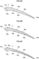
FIG. 4A] FIG. 4A is a cross-sectional view of a first blade of a second embodiment. - [
FIG. 4B] FIG. 4B is a cross-sectional view of a second blade of the second embodiment. - [
FIG. 4C] FIG. 4C is a cross-sectional view of a third blade of the second embodiment. - Embodiments of the present invention will be described in detail with reference to the drawings. Note that the following embodiments and variations are merely beneficial examples in nature, and are not intended to limit the scope of the invention, which is solely defined by the appended claims.
- A first embodiment will be described. A propeller fan (10) of this embodiment is configured as an axial fan. The propeller fan (10) is provided, for example, in a heat source unit of an air conditioner, and is used to supply outdoor air to a heat-source-side heat exchanger.
- As shown in
FIG. 1 , the propeller fan (10) of this embodiment includes one hub (15) and three blades (20a, 20b, 20c). The hub (15) and the three blades (20a to 20c) are integrally formed. The propeller fan (10) is made of a resin. - The hub (15) is formed into a shape of a cylinder whose tip end face is closed. The hub (15) is attached to a drive shaft of a fan motor. The center axis of the hub (15) is a rotational center axis (11) of the propeller fan (10).
- Each blade (20a to 20c) is arranged to project outwardly from the outer peripheral surface of the hub (15). The three blades (20a to 20c) are arranged at predetermined intervals in the circumferential direction of the hub (15). Each blade (20a to 20c) has a shape extending toward the outside in the radial direction of the propeller fan (10). The shapes and circumferential pitches of the blades (20a to 20c) will be described below.
- Each blade (20a to 20c) has an end portion located near a radially central portion of the propeller fan (10) (i.e., near the hub (15)) and serving as a blade root (21a, 21b, 21c), and an end portion located near the radially outer end of the propeller fan (10) and serving as a blade end (22a, 22b, 22c). The blade roots (21a to 21c) of the blades (20a to 20c) are joined to the hub (15).
- Each blade (20a to 20c) has a front edge in the rotation direction of the propeller fan (10) as a leading edge (23a, 23b, 23c), and a rear edge in the rotation direction of the propeller fan (10) as a trailing edge (24a, 24b, 24c). The leading edge (23a to 23c) and the trailing edge (24a to 24c) of the blade (20a to 20c) extend from the blade root (21a to 21c) toward the blade end (22a to 22c) and thus extend toward the outer circumferential side of the propeller fan (10).
- Each blade (20a to 20c) is inclined with respect to a plane orthogonal to the rotational center axis (11) of the propeller fan (10). Specifically, the blade (20a to 20c) is arranged such that the leading edge (23a to 23c) is located near a tip end of the hub (15), and the trailing edge (24a to 24c) is located near a base end of the hub (15). The blade (20a to 20c) is configured such that a front surface (a downward face in
FIGS. 2A to 2C ) in the rotation direction of the propeller fan (10) is a positive pressure surface (25a, 25b, 25c), and a rear surface (an upward face inFIGS. 2A to 2C ) in the rotation direction of the propeller fan (10) is a negative pressure surface (26a, 26b, 26c). - The shapes of the blades (20) will be described with reference to
FIG. 1 and2A to 2C . - The blade cross sections shown in
FIGS. 2A to 2C are respectively views in which curved cross sections, of the blades (20a to 20c), located at a distance r from the rotational center axis (11) of the propeller fan (10) are shown in a flattened state. The blades (20a to 20c) are respectively cambered so as to bulge toward the negative pressure surfaces (26a to 26c). - In the blade cross section of each blade (20a to 20c), a line segment connecting the leading edge (23a to 23c) and the trailing edge (24a to 24c) is a chord line (31), and an angle formed by the chord line (31) with the "plane orthogonal to the rotational center axis (11) of the propeller fan (10)" is an attaching angle α. The chord length Lc is a value obtained through dividing the length rθ of an arc having a radius r and a central angle θ by a cosine cosα with respect to the attaching angle α (Lc = rθ/cosα). Note that θ is a central angle of the blade (20) at the position located at the distance r from the rotational center axis (11) of the propeller fan (10) (see
FIG. 1 ), and the unit thereof is radian. - In each of the blade cross sections shown in
FIGS. 2A to 2C , a line connecting the midpoints of the positive pressure surface (25a to 25c) and the negative pressure surface (26a to 26c) is a camber line (32a, 32b, 32c), and the distance from the chord line (31) to the camber line (32a to 32c) is a camber H. The shape of the camber line (32a to 32c) in each blade cross section is determined by the distance L from the leading edge (23a to 23c) to an optional point X on the chord line (31), the distance from the point X to the camber line (32a to 32c) (i.e., the camber H at the point X), and the chord length Lc. - The camber lines (32a to 32c) of the blades (20a to 20c) have the same shape. Specifically, the blades (20a to 20c) have the same camber H at the optional point X on the chord line (31) and the same chord length Lc in the blade cross section located at the optional distance r from the rotational center axis (11) of the propeller fan (10).
- Note that two objects cannot actually have completely the same shape and size. Thus, "the same" as used herein includes not only the case where they are completely the same, but also the case where they are different by about a usual tolerance. In other words, "the same" as used herein further includes the case where it can be said that they are not completely the same but substantially the same.
- Projections of the blades (20a to 20c) on the plane orthogonal to the rotational center axis (11) of the propeller fan (10) have the same shape. In other words, the shapes of the blades (20a to 20c) shown in
FIG. 1 (i.e., the shapes of the blades viewed from the rotational center axis (11) of the propeller fan (10)) are the same. Thus, the leading edges (23a to 23c) of the blades (20a to 20c) have the same shape, and the trailing edges (24a to 24c) of the blades (20a to 20c) have the same shape. - A portion of each blade (20a to 20c) extending along the associated leading edge (23a to 23c) forms a leading edge portion (41a, 41b, 41c), and the remaining portion thereof forms a blade body portion (42a, 42b, 42c).
- The leading edge portions (41a to 41c) are respectively regions of the blades (20a to 20c) near the leading edges (23a to 23c), and respectively extend across the lengths of the leading edges (23a to 23c). A region of each blade (20a to 20c) of this embodiment that is closer to the associated leading edge (23a to 23c) than a portion of the blade (20a to 20c) having the largest thickness t1, t2, t3 (an associated one of phantom planes Z shown in
FIGS. 2A to 2C ) forms the leading edge portion (41a to 41c). The thickness t1, t2, t3 of each blade (20a to 20c) is the interval between the positive pressure surface (25a to 25c) and the negative pressure surface (26a to 26c) on a straight line perpendicular to the camber line (32a to 32c). - The blade body portions (42a to 42c) respectively extend from the leading edge portions (41a to 41c) to the trailing edges (24a to 24c). A region of each blade (20a to 20c) other than the leading edge portion (41a to 41c) forms the blade body portion (42a to 42c).
- The leading edge portions (41a to 41c) of the blades (20a to 20c) have the same shape. In other words, the leading edges (23a to 23c) of the leading edge portions (41a to 41c) of the blades (20a to 20c) have the same shape, portions of the camber lines (32a to 32c) in the leading edge portions (41a to 41c) have the same shape, and the thicknesses t1, t2, and t3 of the leading edge portions (41a to 41c) are the same.
- The blade body portions (42a to 42c) of the blades (20a to 20c) have different thicknesses t1, t2, and t3.
- As shown in
FIG. 2B , the average thickness t2 of the blade body portion (42b) of a second blade (20b) is smaller than the average thickness t1 of the blade body portion (42a) of a first blade (20a). The difference (t1 - t2) between the thickness t2 of the blade body portion (42b) of the second blade (20b) and the thickness t1 of the blade body portion (42a) of the first blade (20a) gradually increases from the leading edge portion (41b) toward the trailing edge (24a to 24c), becomes maximum at the intermediate position between the leading edge portion (41b) and the trailing edge (24a to 24c), and gradually decreases from the position at which the difference (t1 - t2) is maximum toward the trailing edge (24a to 24c). - As shown in
FIG. 2C , the average thickness t3 of the blade body portion (42c) of a third blade (20c) is smaller than the average thickness t2 of the blade body portion (42b) of the second blade (20b). The difference (t2 - t3) between the thickness t3 of the blade body portion (42c) of the third blade (20c) and the thickness t2 of the blade body portion (42b) of the second blade (20b) gradually increases from the leading edge portion (41c) toward the trailing edge (24a to 24c), becomes maximum at the intermediate position between the leading edge portion (41c) and the trailing edge (24a to 24c), and gradually decreases from the position at which the difference (t2 - t3) is maximum toward the trailing edge (24a to 24c). - In the propeller fan (10) of this embodiment, the blades (20a to 20c) have different circumferential pitches ϕ1, ϕ2, and ϕ3.
- Here, in each blade (20a to 20c), a plane including the rotational center axis (11) of the propeller fan (10) and being in contact with the leading edge (23a to 23c) of the blade (20a to 20c) is defined as a front end plane (35a, 35b, 35c). The front end plane (35a) of the first blade (20a) includes the rotational center axis (11) of the propeller fan (10), and is in contact with the leading edge (23a) of the first blade (20a). The front end plane (35b) of the second blade (20b) includes the rotational center axis (11) of the propeller fan (10), and is in contact with the leading edge (23b) of the second blade (20b). The front end plane (35c) of the third blade (20c) includes the rotational center axis (11) of the propeller fan (10), and is in contact with the leading edge (23c) of the third blade (20c).
- The circumferential pitch ϕ1, ϕ2, ϕ3 of each blade (20a to 20c) is an angle formed between the front end plane (35a, 35b, 35c) of the blade (20a, 20b, 20c) and the front end plane (35b, 35c, 35a) of another one of the blades (20b, 20c, 20a) located behind the blade (20a to 20c) in the rotation direction of the propeller fan (10). Specifically, the circumferential pitch ϕ1 of the first blade (20a) is an angle formed between the front end plane (35a) of the first blade (20a) and the front end plane (35b) of the second blade (20b). The circumferential pitch ϕ2 of the second blade (20b) is an angle formed between the front end plane (35b) of the second blade (20b) and the front end plane (35c) of the third blade (20c). The circumferential pitch ϕ3 of the third blade (20c) is an angle formed between the front end plane (35c) of the third blade (20c) and the front end plane (35a) of the first blade (20a).
- In the propeller fan (10) of this embodiment, the circumferential pitches ϕ1, ϕ2, and ϕ3 of the first, second, and third blades (20a), (20b), and (20c) become increasingly greater in this order. In other words, the circumferential pitch ϕ3 of the third blade (20c) is greater than the circumferential pitch ϕ2 of the second blade (20b), and the circumferential pitch ϕ2 of the second blade (20b) is greater than the circumferential pitch ϕ1 of the first blade (20a) (ϕ1<ϕ2<ϕ3). In the propeller fan (10) of this embodiment, the circumferential pitch ϕ1 of the first blade (20a) is 114°, the circumferential pitch ϕ2 of the second blade (20b) is 119°, and the circumferential pitch ϕ3 of the third blade (20c) is 127°. Note that values of the circumferential pitches ϕ1, ϕ2, and ϕ3 shown here are merely examples.
- As described above, the average thicknesses t1, t2, and t3 of the blade body portions (42a to 42c) of the first, second, and third blades (20a), (20b), and (20c) become increasingly smaller in this order. Thus, the masses of the first, second, and third blades (20a), (20b), and (20c) become increasingly smaller in this order. In other words, the mass M3 of the third blade (20c) is smaller than the mass M2 of the second blade (20b), and the mass M2 of the second blade (20b) is smaller than the mass M1 of the first blade (20a) (M3<M2<M1). In the propeller fan (10) of this embodiment, the mass M2 of the second blade (20b) is about 95% of the mass M1 of the first blade (20a), and the mass M3 of the third blade (20c) is about 85% of the mass M1 of the first blade (20a). Note that the ratios among the masses M1, M2, and M3 shown here are merely examples.
- The masses M1, M2, and M3 of the blades (20a to 20c) are determined so that the center of gravity of the propeller fan (10) is positioned on the rotational center axis (11) of the propeller fan (10). The center of gravity of the propeller fan (10) of this embodiment is positioned substantially on the rotational center axis (11) of the propeller fan (10). If the distance from the rotational center axis (11) of the propeller fan (10) to the center of gravity of the propeller fan (10) is approximately equal to a general tolerance, the center of gravity of the propeller fan (10) can be said to be positioned substantially on the rotational center axis (11) of the propeller fan (10).
- The center of gravity of the propeller fan (10) may be slightly apart from the rotational center axis (11) of the propeller fan (10). If the distance between the center of gravity of the propeller fan (10) and the rotational center axis (11) of the propeller fan (10) is generally less than or equal to 0.5% of the outer diameter of the propeller fan (10), the propeller fan (10) is substantially rotationally balanced.
- The outer diameter of the propeller fan (10) is the diameter of a cylindrical surface having a center axis that coincides with the rotational center axis (11) of the propeller fan (10) and circumscribing the propeller fan (10). The outer diameter D of the propeller fan (10) of this embodiment is twice as large as the distance ro from the rotational center axis (11) of the propeller fan (10) to the blade ends (22a to 22c) (D = 2ro).
- The propeller fan (10) of this embodiment is driven by a fan motor connected to the hub (15), and rotates in the clockwise direction of
FIG. 1 . When the propeller fan (10) rotates, air is pushed out in the direction of the rotational center axis (11) of the propeller fan (10) by the blades (20a to 20c). - Aerodynamic forces act on the blades (20a to 20c) of the propeller fan (10). Specifically, in each blade (20a to 20c), the air pressure on the positive pressure surface (25a to 25c) side becomes higher than the atmospheric pressure, and the air pressure on the negative pressure surface (26a to 26c) side becomes lower than the atmospheric pressure. Therefore, lift force is applied to each of the blades (20a to 20c) of the propeller fan (10). The lift force pushes the blades (20a to 20c) in the direction from the positive pressure surface (25a to 25c) toward the negative pressure surface (26a to 26c). The lift force is a reaction force for the force with which each of the blades (20a to 20c) of the propeller fan (10) pushes out air.
- As described above, the blade body portions (42a to 42c) of the blades (20a to 20c) of the propeller fan (10) of this embodiment have different thicknesses t1, t2, and t3. However, the camber lines (32a to 32c) have the same shape, projections of the blades (20a to 20c) on the plane perpendicular to the rotational center axis (11) of the propeller fan (10) have the same shape, and the leading edge portions (41a to 41c) have the same shape. In other words, the shapes of the blades (20a to 20c) significantly affecting the magnitudes of aerodynamic forces acting on the respective blades (20a to 20c) are the same. Thus, the differences among the aerodynamic forces acting on the blades (20a to 20c) having different masses M1, M2, and M3 are reduced.
- Blowing sound of a propeller fan (10) will be described with reference to
FIG. 3 . - In
FIG. 3 , the measurement result of the blowing sound of the propeller fan (10) of this embodiment is indicated by the solid line, and the measurement result of blowing sound of a propeller fan of a comparative example is indicated by the broken line. The propeller fan of the comparative example includes three blades having the same shape as the first blade (20a) of this embodiment. These three blades are circumferentially arranged at regular intervals. In other words, in the propeller fan of the comparative example, the circumferential pitches of the blades are all 120°. - As shown in
FIG. 3 , the propeller fan (10) of this embodiment has a lower sound pressure level in a frequency band including frequencies of NZ noise than the propeller fan of the comparative example, while having a higher sound pressure level in a frequency band adjacent to the frequency band including the frequencies of the NZ noise. - Here, as the difference in sound pressure level between the frequency band including the frequencies of the NZ noise and the frequency band adjacent to the frequency band including the frequencies of the NZ noise increases, the discomfort imparted to a person by the NZ noise increases. As shown in
FIG. 3 , the difference ΔB of the propeller fan (10) of this embodiment between the sound pressure levels in these two frequency bands is smaller than the difference ΔB' of the propeller fan of the comparative example therebetween. Thus, the propeller fan (10) of this embodiment including the blades (20a to 20c) having different circumferential pitches allows the discomfort imparted to a person by the NZ noise to be less than that of the propeller fan of the comparative example. - Unequal circumferential pitches of the blades (20a to 20c) of the propeller fan (10) of this embodiment can reduce the discomfort resulting from the so-called NZ noise, and unequal masses of the blades (20a to 20c) can reduce vibrations of the propeller fan (10). Furthermore, in the propeller fan (10) of this embodiment, one or more of various shapes of the blades (20a to 20c) significantly affecting the aerodynamic forces acting on the blades (20a to 20c) are common among all the blades (20a to 20c). This enables equalization of the aerodynamic forces acting on the blades (20a to 20c) of the propeller fan (10), and can reduce the degree to which noise increases due to different aerodynamic forces acting on the blades (20a to 20c). Thus, this embodiment can provide a high-performance propeller fan (10) capable of reducing the discomfort resulting from NZ noise while reducing the degrees to which noise and vibrations increase.
- In addition, in this embodiment, different thicknesses of the blade body portions (42a to 42c) of the blades (20a to 20c) allow the blades (20a to 20c) to have different masses. The thicknesses of the blade body portions (42a to 42c) insignificantly affect the magnitudes of the aerodynamic forces acting on the blades (20a to 20c). Thus, this embodiment allows the blades (20a to 20c) to have different masses while enabling equalization of the aerodynamic forces acting on all the blades (20a to 20c) of the propeller fan (10).
- In addition, in this embodiment, since the blades (20a to 20c) of the propeller fan (10) have different circumferential pitches and different masses, the differences among the circumferential pitches of the blades (20a to 20c) and the differences among the masses of the blades (20a to 20c) can be minimized. Thus, this embodiment can reliably shorten the distance between the center of gravity and rotational center axis (11) of the propeller fan (10), and allows the propeller fan (10) to be rotationally balanced with ease and reliability.
- In this embodiment, since the blades (20a to 20c) of the propeller fan (10) having different circumferential pitches have different masses, the propeller fan (10) is rotationally balanced. Therefore, the propeller fan (10) of this embodiment that has just been injection-molded has already been rotationally balanced. Therefore, according to this embodiment, the propeller fan (10) including the blades (20a to 20c) having different circumferential pitches can be manufactured without attaching another member, such as a balance weight, to the propeller fan (10).
- A second embodiment will be described. A propeller fan (10) of this embodiment is obtained by changing the shape of blades (20a to 20c) of the propeller fan (10) of the first embodiment. The propeller fan (10) of this embodiment will be described mainly through explaining a difference between the propeller fan (10) of this embodiment and the propeller fan (10) of the first embodiment.
- As shown in
FIGS. 4A to 4C , the blades (20a to 20c) of this embodiment each have a protrusion (45a, 45b, 45c). The protrusion (45a to 45c) protrudes toward the positive pressure surface (25a to 25c) of the blade (20a to 20c), and extends along the leading edge portion (41a to 41c) across the length of the leading edge portion (41a to 41c). The surface of the protrusion (45a to 45c) is a convex surface that is smoothly continuous with a surface of a region of the blade (20a to 20c) adjacent to the protrusion (45a to 45c). The protrusions (45a to 45c) of the blades (20a to 20c) have the same shape. In other words, the leading edge portions (41a to 41c) of the blades (20a to 20c) of this embodiment have the same shape, and the protrusions (45a to 45c) of the blades (20a to 20c) have the same shape. - Each blade (20a to 20c) having the protrusion (45a to 45c) allows air to flow smoothly and separately toward the associated positive pressure surface (25a to 25c) and the associated negative pressure surface (26a to 26c) of the blade at the leading edge (23a to 23c) of the blade (20a to 20c). This can reduce the blowing sound. On the other hand, the protrusions (45a to 45c) are respectively disposed along the leading edges (23a to 23c) of the blades (20a to 20c). Thus, the shape of the protrusions (45a to 45c) relatively significantly affects the aerodynamic forces acting on the blades (20a to 20c). In contrast, the protrusions (45a to 45c) of the blades (20a to 20c) of the propeller fan (10) of this embodiment have the same shape. Thus, according to this embodiment, reducing the differences among the aerodynamic forces acting on the blades (20a to 20c) of the propeller fan (10), and the protrusions (45a to 45c) functioning to adjust the air flow can further reduce the blowing sound of the propeller fan (10).
- The number of blades (20a to 20c) of the propeller fan (10) of each of the foregoing embodiments may be an odd number greater than or equal to five. Alternatively, the number of blades (20a to 20c) of the propeller fan (10) of each of the foregoing embodiments may be an even number.
- Not all but some of the blades of the propeller fan (10) of each of the foregoing embodiments may have different circumferential pitches and different masses.
- In the propeller fan (10) of this embodiment, the camber lines (32a to 32c) of the blades (20a to 20c) have a common shape, projections of the blades (20a to 20c) on the plane perpendicular to the rotational center axis (11) of the propeller fan (10) have a common shape, and the leading edge portions (41a to 41c) of the blades (20a to 20c) have a common shape. Even if the differences among the shapes of "the camber lines (32a to 32c)" of the blades (20a to 20c), the differences among the shapes of "projections of the blades (20a to 20c) on the plane perpendicular to the rotational center axis (11) of the propeller fan (10)," and the differences among the shapes of "the leading edge portions (41a to 41c)" each exceed the usual tolerance, these shapes can be said to be common among the blades (20a to 20c) as long as the differences in shape only slightly affect the aerodynamic forces acting on the blades (20a to 20c).
- The protrusions (45a to 45c) of the blades (20a to 20c) of the propeller fan (10) of the second embodiment merely need to have a common shape.
- As can be seen from the foregoing description, the present invention relates to a propeller fan.
-
- 10
- Propeller Fan
- 11
- Rotational Center Axis
- 15
- Hub
- 20a
- First Blade
- 20b
- Second Blade
- 20c
- Third Blade
- 24a, 24b, 24c
- Trailing Edge
- 25a, 25b, 25c
- Positive Pressure Surface
- 41a, 41b, 41c
- Leading Edge Portion
- 45a, 45b, 45c
- Protrusion
Claims (4)
- A propeller fan (10) comprising:a hub (15) formed into a cylindrical shape; anda plurality of blades (20a to 20c) extending outward from a side of the hub (15),at least two of the blades (20a to 20c) having different circumferential pitches,at least two of the blades (20a to 20c) having different masses so that a center of gravity of the propeller fan (10) is positioned near or on a rotational center axis (11) of the propeller fan (10),projections of the blades (20a to 20c) on a plane orthogonal to the rotational center axis (11) of the propeller fan (10) having a common shape, leading edge portions (41a to 41c) of the blades (20a to 20c) having a common shape,wherein the circumferential pitch of each blade (20a to 20c) is an angle formed between a front end plane (35a to 35c) of the blade (20a to 20c) and a front end plane (35b to 35a) of another one of the blades (20b to 20a) located behind the blade (20a to 20c) in the rotation direction of the propeller fan (10) and the front end plane (35a to 35c) is a plane including the rotational center axis (11) of the propeller fan (10) and being in contact with the leading edge (23a to 23c) of the blade (20a to 20c),characterized in thatregions of the blades (20a to 20c) closer to trailing edges (24a to 24c) than to the leading edge portions (41a to 41c) partly or entirely have different thicknesses, allowing the blades (20a to 20c) to have different masses.
- The propeller fan of claim 1, wherein
all of the blades (20a to 20c) have different circumferential pitches and different masses. - The propeller fan of claim 2, wherein
one of the blades (20a to 20c) having a greater circumferential pitch has a smaller mass. - The propeller fan of any one of claims 1 to 3, whereinthe blades (20a to 20c) each have a protrusion (45a to 45c) extending along an associated one of the leading edge portions (41a to 41c) and protruding toward a positive pressure surface (25a to 25c), andthe protrusions (45a to 45c) of all of the blades (20a to 20c) have a common shape.
Applications Claiming Priority (2)
| Application Number | Priority Date | Filing Date | Title |
|---|---|---|---|
| JP2017119658A JP6536631B2 (en) | 2017-06-19 | 2017-06-19 | Propeller fan |
| PCT/JP2018/020377 WO2018235531A1 (en) | 2017-06-19 | 2018-05-28 | Propeller fan |
Publications (3)
| Publication Number | Publication Date |
|---|---|
| EP3623638A1 EP3623638A1 (en) | 2020-03-18 |
| EP3623638A4 EP3623638A4 (en) | 2021-02-17 |
| EP3623638B1 true EP3623638B1 (en) | 2022-02-09 |
Family
ID=64737199
Family Applications (1)
| Application Number | Title | Priority Date | Filing Date |
|---|---|---|---|
| EP18820896.1A Active EP3623638B1 (en) | 2017-06-19 | 2018-05-28 | Propeller fan |
Country Status (5)
| Country | Link |
|---|---|
| US (1) | US11512709B2 (en) |
| EP (1) | EP3623638B1 (en) |
| JP (1) | JP6536631B2 (en) |
| CN (1) | CN110730868B (en) |
| WO (1) | WO2018235531A1 (en) |
Families Citing this family (1)
| Publication number | Priority date | Publication date | Assignee | Title |
|---|---|---|---|---|
| JP7173939B2 (en) * | 2019-08-26 | 2022-11-16 | ダイキン工業株式会社 | Blower and heat pump unit |
Family Cites Families (11)
| Publication number | Priority date | Publication date | Assignee | Title |
|---|---|---|---|---|
| GB1293553A (en) * | 1969-02-18 | 1972-10-18 | Cav Ltd | Radial flow fans |
| JPH05223093A (en) | 1992-02-07 | 1993-08-31 | Matsushita Electric Ind Co Ltd | Blower |
| JPH05233093A (en) | 1992-02-21 | 1993-09-10 | Nec Corp | Circuit and method for supplying clock signal |
| JPH10176694A (en) * | 1996-12-18 | 1998-06-30 | Nec Corp | Fan |
| JP3235556B2 (en) * | 1998-01-13 | 2001-12-04 | ダイキン工業株式会社 | Impeller for blower |
| IT1316873B1 (en) * | 2000-03-31 | 2003-05-12 | Balance Systems Spa | APPARATUS AND PROCEDURE FOR BALANCING A ROTATING BODY THROUGH A MATERIAL RELATIONSHIP |
| GB0601837D0 (en) | 2006-01-31 | 2006-03-08 | Rolls Royce Plc | An aerofoil assembly and a method of manufacturing an aerofoil assembly |
| CN101285484A (en) | 2007-04-10 | 2008-10-15 | 台达电子工业股份有限公司 | Fan and its impeller |
| JP2010242665A (en) * | 2009-04-08 | 2010-10-28 | Panasonic Corp | Blower impeller |
| JP6577694B2 (en) * | 2013-10-31 | 2019-09-18 | 株式会社日立産機システム | Impeller and axial flow fan provided with the impeller |
| US10480527B2 (en) * | 2017-05-05 | 2019-11-19 | Robert Bosch Gmbh | Axial fan with unbalanced blade spacing |
-
2017
- 2017-06-19 JP JP2017119658A patent/JP6536631B2/en active Active
-
2018
- 2018-05-28 WO PCT/JP2018/020377 patent/WO2018235531A1/en unknown
- 2018-05-28 CN CN201880038659.2A patent/CN110730868B/en active Active
- 2018-05-28 US US16/620,182 patent/US11512709B2/en active Active
- 2018-05-28 EP EP18820896.1A patent/EP3623638B1/en active Active
Also Published As
| Publication number | Publication date |
|---|---|
| US20200088211A1 (en) | 2020-03-19 |
| JP6536631B2 (en) | 2019-07-03 |
| CN110730868B (en) | 2021-05-28 |
| CN110730868A (en) | 2020-01-24 |
| JP2019002378A (en) | 2019-01-10 |
| US11512709B2 (en) | 2022-11-29 |
| EP3623638A1 (en) | 2020-03-18 |
| WO2018235531A1 (en) | 2018-12-27 |
| EP3623638A4 (en) | 2021-02-17 |
Similar Documents
| Publication | Publication Date | Title |
|---|---|---|
| EP1939458B1 (en) | Molded cooling fan | |
| US6375427B1 (en) | Engine cooling fan having supporting vanes | |
| EP3604821B1 (en) | Propeller fan | |
| EP2508760B1 (en) | Counter-rotating axial flow fan | |
| EP2336576A2 (en) | Counter-rotating axial flow fan | |
| EP2949944B1 (en) | Centrifugal fan | |
| CN104641121A (en) | Propeller fan and air conditioner equipped with same | |
| JP2006329099A (en) | Cross flow fan | |
| JP6842563B2 (en) | Centrifugal rotary machine impeller and centrifugal rotary machine | |
| EP3623638B1 (en) | Propeller fan | |
| CN208294835U (en) | Blade and the axial wheel for using it | |
| KR102562563B1 (en) | Turbo fan and air conditioner having the same | |
| JP2000145693A (en) | Multiblade forward fan | |
| JP2013249787A (en) | Propeller fan | |
| JPH0874790A (en) | Propeller fan | |
| JP2902577B2 (en) | Propeller fan | |
| JP6632927B2 (en) | Rotating device | |
| JP6930644B1 (en) | Propeller fan | |
| CN217462650U (en) | Impeller and fan comprising same | |
| US20230104481A1 (en) | Support frame holding arm | |
| CN211950975U (en) | Axial flow fan blade | |
| KR100484825B1 (en) | An axial flow fan | |
| CN208252427U (en) | A kind of impeller | |
| WO2019111973A1 (en) | Propeller fan | |
| JPH0159440B2 (en) |
Legal Events
| Date | Code | Title | Description |
|---|---|---|---|
| STAA | Information on the status of an ep patent application or granted ep patent |
Free format text: STATUS: THE INTERNATIONAL PUBLICATION HAS BEEN MADE |
|
| PUAI | Public reference made under article 153(3) epc to a published international application that has entered the european phase |
Free format text: ORIGINAL CODE: 0009012 |
|
| STAA | Information on the status of an ep patent application or granted ep patent |
Free format text: STATUS: REQUEST FOR EXAMINATION WAS MADE |
|
| 17P | Request for examination filed |
Effective date: 20191210 |
|
| AK | Designated contracting states |
Kind code of ref document: A1 Designated state(s): AL AT BE BG CH CY CZ DE DK EE ES FI FR GB GR HR HU IE IS IT LI LT LU LV MC MK MT NL NO PL PT RO RS SE SI SK SM TR |
|
| A4 | Supplementary search report drawn up and despatched |
Effective date: 20210120 |
|
| RIC1 | Information provided on ipc code assigned before grant |
Ipc: F04D 29/66 20060101ALI20210114BHEP Ipc: F04D 29/38 20060101ALI20210114BHEP Ipc: F04D 29/32 20060101AFI20210114BHEP |
|
| GRAP | Despatch of communication of intention to grant a patent |
Free format text: ORIGINAL CODE: EPIDOSNIGR1 |
|
| STAA | Information on the status of an ep patent application or granted ep patent |
Free format text: STATUS: GRANT OF PATENT IS INTENDED |
|
| INTG | Intention to grant announced |
Effective date: 20210922 |
|
| GRAS | Grant fee paid |
Free format text: ORIGINAL CODE: EPIDOSNIGR3 |
|
| GRAA | (expected) grant |
Free format text: ORIGINAL CODE: 0009210 |
|
| STAA | Information on the status of an ep patent application or granted ep patent |
Free format text: STATUS: THE PATENT HAS BEEN GRANTED |
|
| AK | Designated contracting states |
Kind code of ref document: B1 Designated state(s): AL AT BE BG CH CY CZ DE DK EE ES FI FR GB GR HR HU IE IS IT LI LT LU LV MC MK MT NL NO PL PT RO RS SE SI SK SM TR |
|
| REG | Reference to a national code |
Ref country code: GB Ref legal event code: FG4D |
|
| REG | Reference to a national code |
Ref country code: CH Ref legal event code: EP Ref country code: AT Ref legal event code: REF Ref document number: 1467676 Country of ref document: AT Kind code of ref document: T Effective date: 20220215 |
|
| REG | Reference to a national code |
Ref country code: IE Ref legal event code: FG4D |
|
| REG | Reference to a national code |
Ref country code: DE Ref legal event code: R096 Ref document number: 602018030680 Country of ref document: DE |
|
| REG | Reference to a national code |
Ref country code: LT Ref legal event code: MG9D |
|
| REG | Reference to a national code |
Ref country code: NL Ref legal event code: MP Effective date: 20220209 |
|
| REG | Reference to a national code |
Ref country code: AT Ref legal event code: MK05 Ref document number: 1467676 Country of ref document: AT Kind code of ref document: T Effective date: 20220209 |
|
| PG25 | Lapsed in a contracting state [announced via postgrant information from national office to epo] |
Ref country code: SE Free format text: LAPSE BECAUSE OF FAILURE TO SUBMIT A TRANSLATION OF THE DESCRIPTION OR TO PAY THE FEE WITHIN THE PRESCRIBED TIME-LIMIT Effective date: 20220209 Ref country code: RS Free format text: LAPSE BECAUSE OF FAILURE TO SUBMIT A TRANSLATION OF THE DESCRIPTION OR TO PAY THE FEE WITHIN THE PRESCRIBED TIME-LIMIT Effective date: 20220209 Ref country code: PT Free format text: LAPSE BECAUSE OF FAILURE TO SUBMIT A TRANSLATION OF THE DESCRIPTION OR TO PAY THE FEE WITHIN THE PRESCRIBED TIME-LIMIT Effective date: 20220609 Ref country code: NO Free format text: LAPSE BECAUSE OF FAILURE TO SUBMIT A TRANSLATION OF THE DESCRIPTION OR TO PAY THE FEE WITHIN THE PRESCRIBED TIME-LIMIT Effective date: 20220509 Ref country code: NL Free format text: LAPSE BECAUSE OF FAILURE TO SUBMIT A TRANSLATION OF THE DESCRIPTION OR TO PAY THE FEE WITHIN THE PRESCRIBED TIME-LIMIT Effective date: 20220209 Ref country code: LT Free format text: LAPSE BECAUSE OF FAILURE TO SUBMIT A TRANSLATION OF THE DESCRIPTION OR TO PAY THE FEE WITHIN THE PRESCRIBED TIME-LIMIT Effective date: 20220209 Ref country code: HR Free format text: LAPSE BECAUSE OF FAILURE TO SUBMIT A TRANSLATION OF THE DESCRIPTION OR TO PAY THE FEE WITHIN THE PRESCRIBED TIME-LIMIT Effective date: 20220209 Ref country code: ES Free format text: LAPSE BECAUSE OF FAILURE TO SUBMIT A TRANSLATION OF THE DESCRIPTION OR TO PAY THE FEE WITHIN THE PRESCRIBED TIME-LIMIT Effective date: 20220209 Ref country code: BG Free format text: LAPSE BECAUSE OF FAILURE TO SUBMIT A TRANSLATION OF THE DESCRIPTION OR TO PAY THE FEE WITHIN THE PRESCRIBED TIME-LIMIT Effective date: 20220509 |
|
| PG25 | Lapsed in a contracting state [announced via postgrant information from national office to epo] |
Ref country code: PL Free format text: LAPSE BECAUSE OF FAILURE TO SUBMIT A TRANSLATION OF THE DESCRIPTION OR TO PAY THE FEE WITHIN THE PRESCRIBED TIME-LIMIT Effective date: 20220209 Ref country code: LV Free format text: LAPSE BECAUSE OF FAILURE TO SUBMIT A TRANSLATION OF THE DESCRIPTION OR TO PAY THE FEE WITHIN THE PRESCRIBED TIME-LIMIT Effective date: 20220209 Ref country code: GR Free format text: LAPSE BECAUSE OF FAILURE TO SUBMIT A TRANSLATION OF THE DESCRIPTION OR TO PAY THE FEE WITHIN THE PRESCRIBED TIME-LIMIT Effective date: 20220510 Ref country code: FI Free format text: LAPSE BECAUSE OF FAILURE TO SUBMIT A TRANSLATION OF THE DESCRIPTION OR TO PAY THE FEE WITHIN THE PRESCRIBED TIME-LIMIT Effective date: 20220209 Ref country code: AT Free format text: LAPSE BECAUSE OF FAILURE TO SUBMIT A TRANSLATION OF THE DESCRIPTION OR TO PAY THE FEE WITHIN THE PRESCRIBED TIME-LIMIT Effective date: 20220209 |
|
| PG25 | Lapsed in a contracting state [announced via postgrant information from national office to epo] |
Ref country code: IS Free format text: LAPSE BECAUSE OF FAILURE TO SUBMIT A TRANSLATION OF THE DESCRIPTION OR TO PAY THE FEE WITHIN THE PRESCRIBED TIME-LIMIT Effective date: 20220609 |
|
| PG25 | Lapsed in a contracting state [announced via postgrant information from national office to epo] |
Ref country code: SM Free format text: LAPSE BECAUSE OF FAILURE TO SUBMIT A TRANSLATION OF THE DESCRIPTION OR TO PAY THE FEE WITHIN THE PRESCRIBED TIME-LIMIT Effective date: 20220209 Ref country code: SK Free format text: LAPSE BECAUSE OF FAILURE TO SUBMIT A TRANSLATION OF THE DESCRIPTION OR TO PAY THE FEE WITHIN THE PRESCRIBED TIME-LIMIT Effective date: 20220209 Ref country code: RO Free format text: LAPSE BECAUSE OF FAILURE TO SUBMIT A TRANSLATION OF THE DESCRIPTION OR TO PAY THE FEE WITHIN THE PRESCRIBED TIME-LIMIT Effective date: 20220209 Ref country code: EE Free format text: LAPSE BECAUSE OF FAILURE TO SUBMIT A TRANSLATION OF THE DESCRIPTION OR TO PAY THE FEE WITHIN THE PRESCRIBED TIME-LIMIT Effective date: 20220209 Ref country code: DK Free format text: LAPSE BECAUSE OF FAILURE TO SUBMIT A TRANSLATION OF THE DESCRIPTION OR TO PAY THE FEE WITHIN THE PRESCRIBED TIME-LIMIT Effective date: 20220209 Ref country code: CZ Free format text: LAPSE BECAUSE OF FAILURE TO SUBMIT A TRANSLATION OF THE DESCRIPTION OR TO PAY THE FEE WITHIN THE PRESCRIBED TIME-LIMIT Effective date: 20220209 |
|
| REG | Reference to a national code |
Ref country code: DE Ref legal event code: R097 Ref document number: 602018030680 Country of ref document: DE |
|
| PG25 | Lapsed in a contracting state [announced via postgrant information from national office to epo] |
Ref country code: AL Free format text: LAPSE BECAUSE OF FAILURE TO SUBMIT A TRANSLATION OF THE DESCRIPTION OR TO PAY THE FEE WITHIN THE PRESCRIBED TIME-LIMIT Effective date: 20220209 |
|
| PLBE | No opposition filed within time limit |
Free format text: ORIGINAL CODE: 0009261 |
|
| STAA | Information on the status of an ep patent application or granted ep patent |
Free format text: STATUS: NO OPPOSITION FILED WITHIN TIME LIMIT |
|
| REG | Reference to a national code |
Ref country code: CH Ref legal event code: PL |
|
| 26N | No opposition filed |
Effective date: 20221110 |
|
| REG | Reference to a national code |
Ref country code: BE Ref legal event code: MM Effective date: 20220531 |
|
| PG25 | Lapsed in a contracting state [announced via postgrant information from national office to epo] |
Ref country code: MC Free format text: LAPSE BECAUSE OF FAILURE TO SUBMIT A TRANSLATION OF THE DESCRIPTION OR TO PAY THE FEE WITHIN THE PRESCRIBED TIME-LIMIT Effective date: 20220209 Ref country code: LU Free format text: LAPSE BECAUSE OF NON-PAYMENT OF DUE FEES Effective date: 20220528 Ref country code: LI Free format text: LAPSE BECAUSE OF NON-PAYMENT OF DUE FEES Effective date: 20220531 Ref country code: CH Free format text: LAPSE BECAUSE OF NON-PAYMENT OF DUE FEES Effective date: 20220531 |
|
| PG25 | Lapsed in a contracting state [announced via postgrant information from national office to epo] |
Ref country code: SI Free format text: LAPSE BECAUSE OF FAILURE TO SUBMIT A TRANSLATION OF THE DESCRIPTION OR TO PAY THE FEE WITHIN THE PRESCRIBED TIME-LIMIT Effective date: 20220209 |
|
| PG25 | Lapsed in a contracting state [announced via postgrant information from national office to epo] |
Ref country code: IE Free format text: LAPSE BECAUSE OF NON-PAYMENT OF DUE FEES Effective date: 20220528 |
|
| PG25 | Lapsed in a contracting state [announced via postgrant information from national office to epo] |
Ref country code: BE Free format text: LAPSE BECAUSE OF NON-PAYMENT OF DUE FEES Effective date: 20220531 |
|
| P01 | Opt-out of the competence of the unified patent court (upc) registered |
Effective date: 20230525 |
|
| PG25 | Lapsed in a contracting state [announced via postgrant information from national office to epo] |
Ref country code: IT Free format text: LAPSE BECAUSE OF FAILURE TO SUBMIT A TRANSLATION OF THE DESCRIPTION OR TO PAY THE FEE WITHIN THE PRESCRIBED TIME-LIMIT Effective date: 20220209 |
|
| PGFP | Annual fee paid to national office [announced via postgrant information from national office to epo] |
Ref country code: FR Payment date: 20230411 Year of fee payment: 6 Ref country code: DE Payment date: 20230404 Year of fee payment: 6 |
|
| PGFP | Annual fee paid to national office [announced via postgrant information from national office to epo] |
Ref country code: GB Payment date: 20230406 Year of fee payment: 6 |
|
| PG25 | Lapsed in a contracting state [announced via postgrant information from national office to epo] |
Ref country code: MK Free format text: LAPSE BECAUSE OF FAILURE TO SUBMIT A TRANSLATION OF THE DESCRIPTION OR TO PAY THE FEE WITHIN THE PRESCRIBED TIME-LIMIT Effective date: 20220209 Ref country code: CY Free format text: LAPSE BECAUSE OF FAILURE TO SUBMIT A TRANSLATION OF THE DESCRIPTION OR TO PAY THE FEE WITHIN THE PRESCRIBED TIME-LIMIT Effective date: 20220209 |