EP3614718B1 - Measurement reporting control methods and related devices - Google Patents
Measurement reporting control methods and related devices Download PDFInfo
- Publication number
- EP3614718B1 EP3614718B1 EP17920640.4A EP17920640A EP3614718B1 EP 3614718 B1 EP3614718 B1 EP 3614718B1 EP 17920640 A EP17920640 A EP 17920640A EP 3614718 B1 EP3614718 B1 EP 3614718B1
- Authority
- EP
- European Patent Office
- Prior art keywords
- terminal
- signaling
- measurement reporting
- preset
- measurement
- Prior art date
- Legal status (The legal status is an assumption and is not a legal conclusion. Google has not performed a legal analysis and makes no representation as to the accuracy of the status listed.)
- Active
Links
- 238000005259 measurement Methods 0.000 title claims description 138
- 238000000034 method Methods 0.000 title claims description 41
- 230000011664 signaling Effects 0.000 claims description 154
- 238000004891 communication Methods 0.000 claims description 42
- 238000012545 processing Methods 0.000 claims description 25
- 230000003213 activating effect Effects 0.000 claims description 8
- 230000006870 function Effects 0.000 description 74
- 238000004590 computer program Methods 0.000 description 15
- 238000010586 diagram Methods 0.000 description 11
- 238000005516 engineering process Methods 0.000 description 6
- 230000008569 process Effects 0.000 description 6
- 230000009286 beneficial effect Effects 0.000 description 5
- 238000007726 management method Methods 0.000 description 4
- 238000013500 data storage Methods 0.000 description 3
- 238000010295 mobile communication Methods 0.000 description 3
- 238000013461 design Methods 0.000 description 2
- 230000009977 dual effect Effects 0.000 description 2
- 230000007774 longterm Effects 0.000 description 2
- 230000008520 organization Effects 0.000 description 2
- 230000000737 periodic effect Effects 0.000 description 2
- 239000007787 solid Substances 0.000 description 2
- 230000001133 acceleration Effects 0.000 description 1
- 230000004913 activation Effects 0.000 description 1
- 230000002776 aggregation Effects 0.000 description 1
- 238000004220 aggregation Methods 0.000 description 1
- 230000005540 biological transmission Effects 0.000 description 1
- 230000009849 deactivation Effects 0.000 description 1
- 238000007599 discharging Methods 0.000 description 1
- VJYFKVYYMZPMAB-UHFFFAOYSA-N ethoprophos Chemical compound CCCSP(=O)(OCC)SCCC VJYFKVYYMZPMAB-UHFFFAOYSA-N 0.000 description 1
- 230000005484 gravity Effects 0.000 description 1
- 238000012905 input function Methods 0.000 description 1
- 230000010354 integration Effects 0.000 description 1
- 230000003993 interaction Effects 0.000 description 1
- 239000004973 liquid crystal related substance Substances 0.000 description 1
- 238000012544 monitoring process Methods 0.000 description 1
- 230000003287 optical effect Effects 0.000 description 1
- 239000013307 optical fiber Substances 0.000 description 1
- 239000004065 semiconductor Substances 0.000 description 1
- 238000001356 surgical procedure Methods 0.000 description 1
- 230000001960 triggered effect Effects 0.000 description 1
Images


Classifications
-
- H—ELECTRICITY
- H04—ELECTRIC COMMUNICATION TECHNIQUE
- H04W—WIRELESS COMMUNICATION NETWORKS
- H04W24/00—Supervisory, monitoring or testing arrangements
- H04W24/10—Scheduling measurement reports ; Arrangements for measurement reports
-
- H—ELECTRICITY
- H04—ELECTRIC COMMUNICATION TECHNIQUE
- H04W—WIRELESS COMMUNICATION NETWORKS
- H04W52/00—Power management, e.g. TPC [Transmission Power Control], power saving or power classes
- H04W52/02—Power saving arrangements
- H04W52/0209—Power saving arrangements in terminal devices
- H04W52/0212—Power saving arrangements in terminal devices managed by the network, e.g. network or access point is master and terminal is slave
-
- H—ELECTRICITY
- H04—ELECTRIC COMMUNICATION TECHNIQUE
- H04W—WIRELESS COMMUNICATION NETWORKS
- H04W24/00—Supervisory, monitoring or testing arrangements
- H04W24/02—Arrangements for optimising operational condition
-
- H—ELECTRICITY
- H04—ELECTRIC COMMUNICATION TECHNIQUE
- H04W—WIRELESS COMMUNICATION NETWORKS
- H04W36/00—Hand-off or reselection arrangements
- H04W36/0005—Control or signalling for completing the hand-off
- H04W36/0083—Determination of parameters used for hand-off, e.g. generation or modification of neighbour cell lists
- H04W36/0085—Hand-off measurements
- H04W36/0088—Scheduling hand-off measurements
-
- H—ELECTRICITY
- H04—ELECTRIC COMMUNICATION TECHNIQUE
- H04W—WIRELESS COMMUNICATION NETWORKS
- H04W48/00—Access restriction; Network selection; Access point selection
- H04W48/16—Discovering, processing access restriction or access information
-
- H—ELECTRICITY
- H04—ELECTRIC COMMUNICATION TECHNIQUE
- H04W—WIRELESS COMMUNICATION NETWORKS
- H04W52/00—Power management, e.g. TPC [Transmission Power Control], power saving or power classes
- H04W52/02—Power saving arrangements
- H04W52/0203—Power saving arrangements in the radio access network or backbone network of wireless communication networks
- H04W52/0206—Power saving arrangements in the radio access network or backbone network of wireless communication networks in access points, e.g. base stations
Definitions
- the present application relates to the technical field of communications, and in particular, to a method for controlling measurement reporting and related devices .
- the network device needs to configure a neighboring cell for User Equipment (UE) to control the UE to switch to the neighboring cell when needing a cell handover.
- UE User Equipment
- the main purpose of the measurement reporting of the terminal is based on the mobility of the network side control.
- the network side determines whether to initiate the handover according to the measurement reporting of the terminal, thereby ensuring the service continuity of the terminal user and the user's service experience.
- the reporting of the measurement report is controlled by an RRC configuration measurement.
- the embodiments of the present application provide a method for controlling measurement reporting, including:
- the embodiments of the present application provide a method for controlling measurement reporting, including: sending, by a network device, a preset signaling, wherein the preset signaling is used by the terminal to activate or deactivate a measurement reporting function of the terminal to control reporting of a measurement report.
- the terminal receives the preset signaling from the network device, the preset signaling being used to activate or deactivate the measurement reporting function of the terminal; and secondly, the terminal controls the reporting of the measurement report according to the preset signaling.
- the embodiments of the present application reduce air interface signaling load and reduce power consumption of the terminal.
- the fifth generation of mobile communication technology (5th-Generation, 5G) New Radio (NR) is a newly proposed topic in the 3rd Generation Partnership Project (3GPP) organization.
- 3GPP 3rd Generation Partnership Project
- 5G NR New Radio
- the main application scenarios of 5G are: enhance Mobile Broadband (eMBB), Ultra-reliable and Low Latency Communications (URLLC), and massive machine type of communication (mMTC).
- eMBB still aims at obtaining multimedia content, services and data for the user, and its demand is growing rapidly.
- URLLC ultra-reliable and Low Latency Communications
- mMTC massive machine type of communication
- eMBB still aims at obtaining multimedia content, services and data for the user, and its demand is growing rapidly.
- the typical applications of URLLC include: industrial automation, power automation, telemedicine operations (surgery), and traffic safety.
- the typical features of mMTC include: high connection density, small data volume, delay-insensitive service, low cost and long life of the module, and the like.
- some of the above scenarios do not require the terminal to report the measurement result, although the measurement time is triggered or the measurement reporting period has arrived.
- the neighboring cell of the serving cell has only one cell.
- the network side does not need to know the measurement result of the terminal, and the terminal only needs to autonomously switch to the target cell according to the measurement result in combination with the network side and the configured switching condition.
- the measurement reporting is also massive, which has a great impact on the air interface signaling load, and this type of terminal may not require high mobility or high timeliness requirement of the service data. Therefore, the mobility problem may not be dealt with at this time, and it is possible to wait for the failure of the wireless link, and then to restore the connection through RRC connection reestablishment.
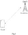
- Fig. 1 is a possible network architecture of an example communication system according to an embodiment of the present application.
- the example communication system may be, for example, a 5G NR system and other such communication systems.
- the example communication system specifically includes a network device and a terminal. When the terminal accesses the mobile communication network provided by the network device, the terminal and the network device may be communicated and connected by using a wireless link, and the communication connection mode may be a single connection mode or a dual connection mode or a multiple connection mode.
- the network device may be an LTE base station or an NR base station (also referred to as a gNB base station), and when the communication mode is the dual connection mode (specifically, it may be implemented by Carrier Aggregation (CA) technology, or a plurality of network devices), and the terminal is connected to a plurality of network devices, the plurality of network devices may be the primary base station MCG and the secondary base station SCG, and the base stations perform data backhaul through the backhaul link (backhaul).
- CA Carrier Aggregation
- the primary base station may be an LTE base station, and the secondary base station may be an LTE base station, or the primary base station may be an NR base station, and the secondary base station may be an LTE base station, or the primary base station may be an NR base station, and the secondary base station may be an NR base station.
- the terminals involved in the embodiments of the present application may include various handheld devices, in-vehicle devices, wearable devices, computing devices having wireless communication function, or other processing devices connected to the wireless modem, and various forms of User Equipment (UE), Mobile Station (MS), terminal device, and the like.
- UE User Equipment
- MS Mobile Station
- terminals the devices mentioned above are collectively referred to as terminals.
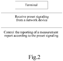
- Fig. 2 which is a method for controlling measurement reporting provided by an embodiment of the present application, the method is applied to the foregoing example communication system, and the method includes the following steps.
- the terminal receives preset signaling from the network device, the preset signaling being used to activate or deactivate a measurement reporting function of the terminal.
- the control priority of the preset signaling is higher than the control priority of the radio resource control (RRC) measurement configuration.
- the RRC measurement configuration includes a measurement object, a measurement reporting, and other information.
- the terminal controls reporting of a measurement report according to the preset signaling.
- the terminal firstly receives the preset signaling from the network device, the preset signaling being used to activate or deactivate the measurement reporting function of the terminal; and secondly, the terminal controls reporting of the measurement report according to the preset signaling. It can be seen that, in the embodiments of the present application, the terminal reports the measurement report under control of the network device, instead of relying entirely on the measurement reporting configuration on the RRC side, so as to prevent the terminal from frequently reporting the measurement report based on the measurement reporting configuration on the RRC side, which is beneficial to reduce the air interface signaling load and reduce the power consumption of the terminal.
- the preset signaling includes first signaling, where the first signaling is used to indicate to deactivate the measurement reporting function of the terminal.
- the measurement reporting function includes a periodic type measurement reporting function and an event type measurement reporting function.
- the terminal controls the reporting of the measurement report according to the preset signaling, including: determining, by the terminal, that the measurement reporting function of the terminal is disabled within a preset time period according to the first signaling.
- the preset time period may be configured by the network device or configured by the terminal, which is not limited herein.
- the preset signaling includes second signaling, where the second signaling is used to indicate to activate the measurement reporting function of the terminal.
- the terminal controls the reporting of the measurement report according to the preset signaling, including: determining, by the terminal, that the measurement reporting function of the terminal is enabled within a preset time period according to the second signaling.
- the preset time period may be configured by the network device or configured by the terminal, which is not limited herein.
- the type of the preset signaling includes any one of the following: a physical downlink control channel (PDCCH) signaling, a medium access control (MAC) control unit (CE), and radio resource control (RRC) signaling.
- a physical downlink control channel (PDCCH) signaling a physical downlink control channel (PDCCH) signaling, a medium access control (MAC) control unit (CE), and radio resource control (RRC) signaling.
- PDCCH physical downlink control channel
- CE medium access control unit
- RRC radio resource control
- the number of bit of the field in the preset signaling for activating or deactivating the measurement reporting function of the terminal is 1.
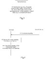
- Fig. 3 is a method for controlling measurement reporting provided by an embodiment of the present application, the method is applied to the foregoing example communication system, and the method includes the following steps.
- the network device sends preset signaling, where the preset signaling is used by the terminal to activate or deactivate a measurement reporting function of the terminal to control reporting of a measurement report.
- the network device may generate the preset signaling for the terminal according to at least one of the following information: a load condition of the network device, and/or a type of the terminal, and/or an environment in which the terminal is located, and the like, which is not limited here.
- the terminal firstly receives the preset signaling from the network device, the preset signaling being used to activate or deactivate the measurement reporting function of the terminal; and secondly, the terminal controls the reporting of the measurement report according to the preset signaling. It can be seen that, in the embodiments of the present application, the terminal reports the measurement report under control of the network device, instead of relying entirely on the measurement reporting configuration on the RRC side, so as to prevent the terminal from frequently reporting the measurement report based on the measurement reporting configuration on the RRC side, which is beneficial to reduce the air interface signaling load and reduce power consumption of the terminal.
- the preset signaling includes first signaling, where the first signaling is used to indicate to deactivate the measurement reporting function of the terminal.
- the measurement reporting function includes a periodic type measurement reporting function and an event type measurement reporting function.
- the first signaling is used by the terminal to disable the measurement reporting function of the terminal within a preset time period.
- the preset signaling includes a second signaling, where the second signaling is used to indicate to activate the measurement reporting function of the terminal.
- the second signaling is used by the terminal to enable the measurement reporting function of the terminal within a preset time period.
- the type of the preset signaling includes any one of the following: a physical downlink control channel (PDCCH) signaling, a medium access control (MAC) control unit (CE), and radio resource control (RRC) signaling.
- a physical downlink control channel (PDCCH) signaling a physical downlink control channel (PDCCH) signaling, a medium access control (MAC) control unit (CE), and radio resource control (RRC) signaling.
- PDCCH physical downlink control channel
- CE medium access control unit
- RRC radio resource control
- the number of bit of the field in the preset signaling for activating or deactivating the measurement reporting function of the terminal is 1.
- Fig. 4 is a method for controlling measurement reporting provided by an embodiment of the present application. Referring to Fig. 4 , the method is applied to the foregoing example communication system, and the method includes the following steps.
- the network device sends preset signaling, where the preset signaling is used by the terminal to activate or deactivate a measurement reporting function of the terminal to control reporting of a measurement report.
- the terminal receives the preset signaling from the network device, where the preset signaling is used to activate or deactivate the measurement reporting function of the terminal.
- the terminal controls reporting of a measurement report according to the preset signaling.
- the terminal firstly receives the preset signaling from the network device, the preset signaling being used to activate or deactivate the measurement reporting function of the terminal; and secondly, the terminal controls the reporting of the measurement report according to the preset signaling. It can be seen that, in the embodiments of the present application, the terminal reports the measurement report under control of the network device, instead of relying entirely on the measurement reporting configuration on the RRC side, so as to prevent the terminal from frequently reporting the measurement report based on the measurement reporting configuration on the RRC side, which is beneficial to reduce the air interface signaling load and reduce power consumption of the terminal.
- Fig. 5 is a schematic structural diagram of a terminal according to an embodiment of the present disclosure.
- the terminal includes a processor, a memory, a communication interface, and one or more programs.
- the one or more programs are stored in the memory and configured to be executed by the processor, and the programs include instructions for performing the following steps:
- the terminal firstly receives the preset signaling from the network device, the preset signaling being used to activate or deactivate the measurement reporting function of the terminal; and secondly, the terminal controls the reporting of the measurement report according to the preset signaling. It can be seen that, in the embodiments of the present application, the terminal to reports the measurement report under control of the network device, instead of relying entirely on the measurement reporting configuration on the RRC side, so as to prevent the terminal from frequently reporting the measurement report based on the measurement reporting configuration on the RRC side, which is beneficial to reduce the air interface signaling load and reduce power consumption of the terminal.
- the preset signaling includes first signaling, where the first signaling is used to indicate to deactivate the measurement reporting function of the terminal.
- the instructions in the programs are specifically configured to perform the following operation: determining to disable the measurement reporting function of the terminal within a preset time period according to the first signaling.
- the preset signaling includes a second signaling, where the second signaling is used to indicate to activate the measurement reporting function of the terminal.
- the instructions in the programs are specifically configured to perform the following operation: determining to enable the measurement reporting function of the terminal within a preset time period according to the second signaling.
- the type of the preset signaling includes any one of the following: a physical downlink control channel (PDCCH) signaling, a medium access control (MAC) control unit (CE), and radio resource control (RRC) signaling.
- a physical downlink control channel (PDCCH) signaling a physical downlink control channel (PDCCH) signaling, a medium access control (MAC) control unit (CE), and radio resource control (RRC) signaling.
- PDCCH physical downlink control channel
- CE medium access control unit
- RRC radio resource control
- the number of bit of the field in the preset signaling for activating or deactivating the measurement reporting function of the terminal is 1.
- Fig. 6 is a schematic structural diagram of a network device according to an embodiment of the present disclosure.
- the network device includes a processor, a memory, a transceiver, and one or more programs.
- the one or more programs are stored in the memory and configured to be executed by the processor, and the programs include instructions for performing the following steps:
- the preset signaling being used by the terminal to activate or deactivate a measurement reporting function of the terminal to control reporting of a measurement report.
- the network device sends the preset signaling, where the preset signaling is used to activate or deactivate the measurement reporting function of the terminal; and secondly, the network device controls the reporting of the measurement report according to the preset signaling.
- the terminal reports the measurement report under control of the network device, instead of relying entirely on the measurement reporting configuration on the RRC side, so as to prevent the terminal from frequently reporting the measurement report based on the measurement reporting configuration on the RRC side, which is beneficial to reduce the air interface signaling load and reduce power consumption of the terminal.
- the preset signaling includes first signaling, where the first signaling is used to indicate to deactivate the measurement reporting function of the terminal.
- the first signaling is used by the terminal to disable the measurement reporting function of the terminal within a preset time period.
- the preset signaling includes a second signaling, where the second signaling is used to indicate to activate the measurement reporting function of the terminal.
- the second signaling is used by the terminal to enable the measurement reporting function of the terminal within a preset time period.
- the type of the preset signaling includes any one of the following: a physical downlink control channel (PDCCH) signaling, a medium access control (MAC) control unit (CE), and radio resource control (RRC) signaling.
- a physical downlink control channel (PDCCH) signaling a physical downlink control channel (PDCCH) signaling, a medium access control (MAC) control unit (CE), and radio resource control (RRC) signaling.
- PDCCH physical downlink control channel
- CE medium access control unit
- RRC radio resource control
- the number of bit of the field in the preset signaling for activating or deactivating the measurement reporting function of the terminal is 1.
- the terminal and the network device include corresponding hardware structures and/or software modules for performing various functions.
- the terminal and the network device include corresponding hardware structures and/or software modules for performing various functions.
- the present application may be implemented by hardware or a combination of hardware and computer software. Whether a certain function is executed by hardware or hardware driven by computer software depends on particular applications and design constraint conditions of the technical solutions. Those skilled in the art may use different methods to implement the described functions for each particular application, but it should not be deemed that the implementations go beyond the scope of the present application.
- the embodiments of the present disclosure may divide function units for the terminal and the network side device according to the above method examples, for instance, it is possible to divide each function unit corresponding to each function, or it is possible to integrate two or more functions into one processing unit.
- the integrated unit above may either be implemented in the form of hardware, or in the form of software program modules. It should be noted that the division of units in the embodiments of the present disclosure is schematic and is only a logical function division, and there may be other division modes in actual implementation.
- Fig. 7 illustrates a block diagram of a possible functional unit composition of the terminal involved in the above embodiments.
- the terminal 700 includes a processing unit 702 and a communication unit 703.
- the processing unit 702 is used to control and manage actions of the terminal.
- the processing unit 702 is used to support the terminal to perform steps 201, 202 in Fig. 2 , steps 402, 403 in Fig. 4 , and/or other processes for the techniques described herein.
- the communication unit 703 is used to support communications between the terminal and other devices, such as communication with the network side device shown in Fig. 5 .
- the terminal may further include a storage unit 701 for storing program codes and data of the terminal.
- the processing unit 702 may be a processor or a controller, for example, a Central Processing Unit (CPU), a general purpose processor, a Digital Signal Processor (DSP), an Application-Specific Integrated Circuit (ASIC), a Field Programmable Gate Array (FPGA), or other programmable logic device, transistor logic device, hardware components or any combination thereof.
- the processing unit may implement or execute various exemplary logical blocks, modules, and circuits described in connection with the present disclosure.
- the processor may also be a combination that implements computing functions, such as a combination that includes one or more microprocessors, a combination of DSP and the microprocessor, and the like.
- the communication unit 703 may be a transceiver, a transceiver circuit, etc., and the storage unit 701 may be a memory.
- the processing unit 702 is configured to receive preset signaling from the network device by using the communication unit 703, where the preset signaling is used to activate or deactivate a measurement reporting function of the terminal; and control reporting of a measurement report according to the preset information.
- the preset signaling includes first signaling, where the first signaling is used to indicate to deactivate the measurement reporting function of the terminal.
- the processing unit 702 is specifically configured to: determine to disable the measurement reporting function of the terminal in a preset time period according to the first signaling.
- the preset signaling includes a second signaling, where the second signaling is used to indicate to activate the measurement reporting function of the terminal.
- the processing unit is configured to: determine to enable the measurement reporting function of the terminal a preset time period according to the second signaling.
- the type of the preset signaling includes any one of the following: a physical downlink control channel (PDCCH) signaling, a medium access control (MAC) control unit (CE), and radio resource control (RRC) signaling.
- a physical downlink control channel (PDCCH) signaling a physical downlink control channel (PDCCH) signaling, a medium access control (MAC) control unit (CE), and radio resource control (RRC) signaling.
- PDCCH physical downlink control channel
- CE medium access control unit
- RRC radio resource control
- the number of bit of the field in the preset signaling for activating or deactivating the measurement reporting function of the terminal is 1.
- the processing unit 702 is a processor
- the communication unit 703 is a communication interface
- the storage unit 701 is a memory
- the terminal involved in the embodiments of the present application may be the terminal shown in Fig. 5 .
- Fig. 8 illustrates a block diagram of a possible functional unit composition of the network device involved in the above embodiments.
- the network device 800 includes a processing unit 802 and a communication unit 803.
- the processing unit 802 is configured to control and manage actions of the network device.
- the processing unit 802 is configured to support the network device to perform step 301 in Fig. 3 , 401 in Fig. 4 , and/or other processes for the techniques described herein.
- the communication unit 803 is used to support communications between the network device and other devices, such as communication with the terminal shown in Fig. 4 .
- the network device may further include a storage unit 801 for storing program codes and data of the network device.
- the processing unit 802 may be a processor or a controller
- the communication unit 803 may be a transceiver, a transceiver circuit, a radio frequency chip, etc.
- the storage unit 801 may be a memory.
- the processing unit 802 is configured to send preset signaling by using the communication unit 803, where the preset signaling is used by the terminal to activate or deactivate a measurement reporting function of the terminal to control reporting of a measurement report.
- the preset signaling includes first signaling, where the first signaling is used to indicate to deactivate the measurement reporting function of the terminal.
- the first signaling is used by the terminal to disable the measurement reporting function of the terminal within a preset time period.
- the preset signaling includes a second signaling, where the second signaling is used to indicate to activate the measurement reporting function of the terminal.
- the second signaling is used by the terminal to enable the measurement reporting function of the terminal within a preset time period.
- the type of the preset signaling includes any one of the following: a physical downlink control channel (PDCCH) signaling, a medium access control (MAC) control unit (CE), and radio resource control (RRC) signaling.
- a physical downlink control channel (PDCCH) signaling a physical downlink control channel (PDCCH) signaling, a medium access control (MAC) control unit (CE), and radio resource control (RRC) signaling.
- PDCCH physical downlink control channel
- CE medium access control unit
- RRC radio resource control
- the number of bit of the field in the preset signaling for activating or deactivating the measurement reporting function of the terminal is 1.
- the network device involved in the embodiments of the present application may be the network device shown in Fig. 6 .
- the embodiments of the present disclosure also provide another terminal as shown in Fig. 9 .
- the terminal may be any terminal device including a mobile phone, a tablet, a Personal Digital Assistant (PDA), a Point of Sales (POS), an on-board computer, and the like.
- PDA Personal Digital Assistant
- POS Point of Sales
- the mobile phone is taken as the terminal for example.
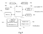
- Fig. 9 illustrates a block diagram of a partial structure of a mobile phone related to the terminal provided by the embodiments of the present disclosure.
- the mobile phone includes: a Radio Frequency (RF) circuit 910, a memory 920, an input unit 930, a display unit 940, a sensor 950, an audio circuit 960, a Wireless Fidelity (WiFi) module 970, a processor 980, a power supply 990, and other components.
- RF Radio Frequency
- a memory 920 includes: a Radio Frequency (RF) circuit 910, a memory 920, an input unit 930, a display unit 940, a sensor 950, an audio circuit 960, a Wireless Fidelity (WiFi) module 970, a processor 980, a power supply 990, and other components.
- WiFi Wireless Fidelity
- the RF circuit 910 may be configured to receive and send information.
- the RF circuit 910 includes, but is not limited to, an antenna, at least one amplifier, a transceiver, a coupler, a Low Noise Amplifier (LNA), a duplexer, and the like.
- the RF circuit 910 may also communicate with a network and other devices via wireless communications.
- the wireless communications above may use any communication standard or protocol, including but not limited to Global System of Mobile Communication (GSM), General Packet Radio Service (GPRS), Code Division Multiple Access (CDMA), Wideband Code Division Multiple Access (WCDMA), Long Term Evolution (LTE), e-mail, Short Messaging Service (SMS), and the like.
- GSM Global System of Mobile Communication
- GPRS General Packet Radio Service
- CDMA Code Division Multiple Access
- WCDMA Wideband Code Division Multiple Access
- LTE Long Term Evolution
- SMS Short Messaging Service
- the memory 920 may be configured to store software programs and modules.
- the processor 980 runs the software programs and modules stored in the memory 920 to perform various functional applications and data processing of the mobile phone.
- the memory 920 may mainly include a program storage region and a data storage region.
- the program storage region may store an operating system, and an application program required by at least one function, etc.
- the data storage region may store data and the like created according to the use of the mobile phone.
- the memory 920 may include a high-speed random access memory, and may also include a non-volatile memory, such as at least one disk memory device, a flash memory device, or other volatile solid storage devices.
- the input unit 930 may be configured to receive input numeric or character information, and generate key signal inputs related to user settings and function control of the mobile phone.
- the input unit 930 may include a fingerprint identification module 931 and other input device 932.
- the fingerprint identification module 931 may collect fingerprint data of the user thereon.
- the input unit 930 may also include other input device 932.
- other input device 932 may include, but is not limited to, one or more of a touch screen, a physical keyboard, function keys (such as a volume control key, a switching key, etc.), a trackball, a mouse, a joystick, and the like.
- the display unit 940 may be configured to display information input by the user or information provided to the user and various menus of the mobile phone.
- the display unit 940 may include a display screen 941.
- the display screen 941 may be configured in the form of a Liquid Crystal Display (LCD), an Organic Light-Emitting Diode (OLED), or the like.
- the fingerprint identification module 931 and the display screen 941 are implemented as two separated components to implement the input and input functions of the mobile phone, in some embodiments, the fingerprint identification module 931 and the display screen 941 may be integrated to achieve the input and play functions of the mobile phone.
- the mobile phone may also include at least one sensor 950 such as a light sensor, a motion sensor, and other sensors.
- the light sensor may include an ambient light sensor and a proximity sensor.
- the ambient light sensor may adjust the brightness of the display screen 941 according to the brightness of the ambient light.
- the proximity sensor may turn off the display screen 941 and/or backlight when the mobile phone is moved close to an ear.
- an accelerometer sensor may detect the magnitude of acceleration in all directions (usually three axes), and may detect the magnitude and direction of gravity when stationary, and may be configured to identify the application of mobile phone attitude (such as horizontal and vertical screen switching, related games, and magnetometer attitude calibration), vibration recognition related functions (such as pedometer, and tap), etc.
- other sensors such as a gyroscope, a barometer, a hygrometer, a thermometer, and an infrared sensor, which can be configured in the mobile phone, they will not be elaborated herein.
- An audio interface between the user and the mobile phone may be provided by the audio circuit 960, a loud speaker 961 and a microphone 962.
- the audio circuit 960 may convert the received audio data into an electrical signal and transmit the converted electrical signal to the loud speaker 961, and the electrical signal is converted to an acoustical signal and played by the loud speaker 961.
- the microphone 962 converts the collected acoustical signal into an electric signal
- the audio circuit 960 receives the electric signal and converts it into audio data
- the audio data is processed by the playback processor 980, and then the audio data is sent to another mobile phone via the RF circuit 910, or the audio data is played to the memory 920 for further processing.
- WiFi is a short-range wireless transmission technology.
- the mobile phone may help the user to send and receive e-mails, browse web pages, access streaming media, and the like via the WiFi module 970 which provides wireless wideband Internet access for the user.
- Fig. 9 illustrates the WiFi module 970, it can be understood that the WiFi module 970 does not belong to the necessary configuration of the mobile phone and may be omitted as necessary without changing the essence of the present disclosure.
- the processor 980 is the control center of the mobile phone, and uses various interfaces and lines to connect various parts of the mobile phone, runs or executes software programs and/or modules stored in the memory 920, and calls data stored in the memory 920 to execute various functions of the mobile phone and process data, thus entirely monitoring the mobile phone.
- the processor 980 may include one or more processing units.
- the processor 980 may integrate an application processor and a modem processor, where the application processor mainly processes an operating system, a user interface, an application program, and the like, while the modem processor mainly processes wireless communications. It may be understood that the above modem processor may not be integrated into the processor 980.
- the mobile phone further includes the power supply 990 (such as a battery) for supplying power to various components.
- the power supply may be logically connected to the processor 980 through a power management system, thereby realizing functions of charging and discharging management, power consumption management and the like through the power management system.
- the mobile phone may also include a camera, a bluetooth module, or the like, which will not be elaborated herein.
- the flow on the terminal side in each step method may be implemented based on the structure of the mobile phone.
- each unit function may be implemented based on the structure of the mobile phone.
- the embodiments of the present disclosure further provide a computer readable storage medium, where the computer readable storage medium stores a computer program for electronic data exchange, and the computer program enables a computer to perform some or all of the steps described by the terminal in the above method embodiments.
- the embodiments of the present disclosure further provide a computer readable storage medium, where the computer readable storage medium stores a computer program for electronic data exchange, and the computer program enables a computer to perform some or all of the steps described by the network device in the above method embodiments.
- the embodiments of the present disclosure further provide a computer program product, where the computer program product includes a non-transitory computer readable storage medium storing a computer program operable to enable a computer to perform some or all of the steps described by the terminal in the above method embodiments.
- the computer program product may be a software install package.
- the embodiments of the present disclosure further provide a computer program product, where the computer program product includes a non-transitory computer readable storage medium storing a computer program operable to enable a computer to perform some or all of the steps described by the network device in the above method embodiments.
- the computer program product may be a software install package.
- the steps of the method or algorithms described in the embodiments of the present disclosure may be implemented in hardware or implemented in a form of executing software instructions by a processor.
- the software instructions may be composed of corresponding software modules, which may be stored in a Random Access Memory (RAM), a flash memory, a Read Only Memory (ROM), an Erasable Programmable ROM (EPROM), an Electrically Erasable Programmable Read-only Memory (EEPROM), a register, a hard disk, a mobile hard disk, a Compact Disc Read-only Memory (CD-ROM), or any other form of storage medium known in the art.
- An exemplary storage medium is coupled to the processor to enable the processor to read information from and write information to the storage medium.
- the storage medium may also be a part of the processor.
- the processor and the storage medium may be located in an ASIC.
- the ASIC may be located in an access network device, a target network device, or a core network device.
- the processor and the storage medium may also exist as discrete components in the access network device, the target network device or the core network device.
- the functions described in the embodiments of the present disclosure may be implemented in whole or in part by software, hardware, firmware, or any combination thereof.
- the functions When the functions are implemented using software, it may be implemented in whole or in part in the form of a computer program product.
- the computer program product includes one or more computer instructions.
- the computer program instructions When the computer program instructions are loaded and executed on a computer, the processes or functions according to the embodiments of the present disclosure are generated in whole or in part.
- the computer may be a general purpose computer, a special purpose computer, a computer network, or other programmable apparatus.
- the computer instruction may be stored in a computer readable storage medium or transmitted from one computer readable storage medium to another computer readable storage medium, for example, the computer instruction may be transmitted from one website site, computer, server or data center to another website site, computer, server or data center by wired (e.g., coaxial cable, optical fiber, Digital Subscriber Line (DSL)) or wireless (e.g., infrared, wireless, microwave, etc) manners.
- the computer readable storage medium may be any available medium that a computer can access or a data storage device such as a server, a data center, or the like that includes one or more available media integration.
- the available medium may be a magnetic medium (e.g., a floppy disk, a hard disk, a magnetic tape), an optical medium (e.g., a Digital Video Disc (DVD)), or a semiconductor medium (e.g., a Solid status Disk (SSD)) or the like.
- a magnetic medium e.g., a floppy disk, a hard disk, a magnetic tape
- an optical medium e.g., a Digital Video Disc (DVD)
- DVD Digital Video Disc
- SSD Solid status Disk
Landscapes
- Engineering & Computer Science (AREA)
- Computer Networks & Wireless Communication (AREA)
- Signal Processing (AREA)
- Computer Security & Cryptography (AREA)
- Mobile Radio Communication Systems (AREA)
- Telephone Function (AREA)
- General Factory Administration (AREA)
- Slot Machines And Peripheral Devices (AREA)
- Confectionery (AREA)
- Arrangements For Transmission Of Measured Signals (AREA)
Description
- The present application relates to the technical field of communications, and in particular, to a method for controlling measurement reporting and related devices .
- To ensure better communication quality, the network device needs to configure a neighboring cell for User Equipment (UE) to control the UE to switch to the neighboring cell when needing a cell handover.
- In the Long Term Evolution (LTE) system, the main purpose of the measurement reporting of the terminal is based on the mobility of the network side control. The network side determines whether to initiate the handover according to the measurement reporting of the terminal, thereby ensuring the service continuity of the terminal user and the user's service experience. The reporting of the measurement report is controlled by an RRC configuration measurement.
- NOKIA CORPORATION ET AL: "E-UTRA Measurement Control in GERAN", 3GPP DRAFT: GP-081169, 3RD GENERATION PARTNERSHIP PROJECT (3GPP), MOBILE COMPETENCE CENTRE; 650, ROUTE DES LUCIOLES; F-06921 SOPHIA-ANTIPOLIS CEDEX; FRANCE; TSG GERAN, Florence; 20 August 2008 (2008-08-20), XP050413571, proposes to allow the activation or deactivation of E-UTRA Neighbouring cell measurement reporting and possibly E-UTRA Neighbouring Cell measurements for multimode GSM/E-UTRA mobile stations in dedicated mode, being served by a GSM cell in which E-UTRA Neighbouring Cell Information is signalled.
US2013229931A1 provides methods of managing a terminal in a heterogeneous network (HetNet) environment. - The invention is defined by the appended claims.
- It is an object of the present invention to provide methods for controlling measurement reporting and related devices, so as to reduce a signaling load of an air interface and reduce power consumption of the terminal. This object is solved by the subject matter of the independent claims.
- The following aspects are provided for illustrative purposes.
- In a first aspect, the embodiments of the present application provide a method for controlling measurement reporting, including:
- receiving, by a terminal, a preset signaling from a network device, wherein the preset signaling is used to activate or deactivate a measurement reporting function of the terminal; and
- controlling, by the terminal, reporting of a measurement report according to the preset signaling.
- In a second aspect, the embodiments of the present application provide a method for controlling measurement reporting, including:
sending, by a network device, a preset signaling, wherein the preset signaling is used by the terminal to activate or deactivate a measurement reporting function of the terminal to control reporting of a measurement report. - It can be seen that, in the embodiments of the present application, firstly, the terminal receives the preset signaling from the network device, the preset signaling being used to activate or deactivate the measurement reporting function of the terminal; and secondly, the terminal controls the reporting of the measurement report according to the preset signaling. The embodiments of the present application reduce air interface signaling load and reduce power consumption of the terminal.
- The drawings required for describing the embodiments or the related art will be briefly described below.
-
Fig. 1 is a network architecture diagram of a possible communication system provided by an embodiment of the present application; -
Fig. 2 is a schematic flowchart of a method for controlling measurement reporting provided by an embodiment of the present application; -
Fig. 3 is a schematic flowchart of another method for controlling measurement reporting provided by an embodiment of the present application; -
Fig. 4 is a schematic flowchart of another method for controlling measurement reporting provided by an embodiment of the present application; -
Fig. 5 is a schematic structural diagram of a terminal according to an embodiment of the present disclosure; -
Fig. 6 is a schematic structural diagram of a network device according to an embodiment of the present application; -
Fig. 7 is a block diagram of a functional unit composition of a terminal according to an embodiment of the present application; -
Fig. 8 is a structural block diagram of a functional unit composition of a network device according to an embodiment of the present disclosure; and -
Fig. 9 is a schematic structural diagram of another terminal according to an embodiment of the present application. - First, some concepts and general operation methods involved in the embodiments of the application will be briefly explained.
- The fifth generation of mobile communication technology (5th-Generation, 5G) New Radio (NR) is a newly proposed topic in the 3rd Generation Partnership Project (3GPP) organization. As the discussion of the new generation of 5G technology gradually deepens, on the one hand, because the communication system is backward compatible, the new technology developed later tends to be compatible with the previously standardized technology; while on the other hand, because there have been a large number of existing designs for the 4G LTE system, in order to achieve compatibility, a lot of flexibility of 5G has to be sacrificed, and the performance is reduced. Therefore, there are currently two parallel studies in the 3GPP organization, where the technical discussion group not considering the backward compatibility is called 5G NR.
- The main application scenarios of 5G are: enhance Mobile Broadband (eMBB), Ultra-reliable and Low Latency Communications (URLLC), and massive machine type of communication (mMTC). Among them, eMBB still aims at obtaining multimedia content, services and data for the user, and its demand is growing rapidly. On the other hand, since eMBB may be deployed in different scenarios, such as indoors, urban areas, and rural areas, the differences in capabilities and demands are relatively large, in this case, it cannot be generalized and should be analyzed in detail in conjunction with specific deployment scenarios. The typical applications of URLLC include: industrial automation, power automation, telemedicine operations (surgery), and traffic safety. The typical features of mMTC include: high connection density, small data volume, delay-insensitive service, low cost and long life of the module, and the like.
- In the 5G network environment, some of the above scenarios do not require the terminal to report the measurement result, although the measurement time is triggered or the measurement reporting period has arrived. For example, in a high-speed train scenario, the neighboring cell of the serving cell has only one cell. In the scenario of the conditional handover, the network side does not need to know the measurement result of the terminal, and the terminal only needs to autonomously switch to the target cell according to the measurement result in combination with the network side and the configured switching condition. For another example, in the mMTC scenario, due to the existence of a large number of connections of MTC devices, the measurement reporting is also massive, which has a great impact on the air interface signaling load, and this type of terminal may not require high mobility or high timeliness requirement of the service data. Therefore, the mobility problem may not be dealt with at this time, and it is possible to wait for the failure of the wireless link, and then to restore the connection through RRC connection reestablishment.
- The technical solutions in the embodiments of the present application will be described below with reference to the accompanying drawings.
-
Fig. 1 is a possible network architecture of an example communication system according to an embodiment of the present application. Referring toFig. 1 , the example communication system may be, for example, a 5G NR system and other such communication systems. The example communication system specifically includes a network device and a terminal. When the terminal accesses the mobile communication network provided by the network device, the terminal and the network device may be communicated and connected by using a wireless link, and the communication connection mode may be a single connection mode or a dual connection mode or a multiple connection mode. When the communication connection mode is the single connection mode, the network device may be an LTE base station or an NR base station (also referred to as a gNB base station), and when the communication mode is the dual connection mode (specifically, it may be implemented by Carrier Aggregation (CA) technology, or a plurality of network devices), and the terminal is connected to a plurality of network devices, the plurality of network devices may be the primary base station MCG and the secondary base station SCG, and the base stations perform data backhaul through the backhaul link (backhaul). The primary base station may be an LTE base station, and the secondary base station may be an LTE base station, or the primary base station may be an NR base station, and the secondary base station may be an LTE base station, or the primary base station may be an NR base station, and the secondary base station may be an NR base station. - In the embodiments of the present application, the terms "network" and "system" are often used interchangeably, and those skilled in the art can understand the meaning thereof. The terminals involved in the embodiments of the present application may include various handheld devices, in-vehicle devices, wearable devices, computing devices having wireless communication function, or other processing devices connected to the wireless modem, and various forms of User Equipment (UE), Mobile Station (MS), terminal device, and the like. For convenience of description, the devices mentioned above are collectively referred to as terminals.
- Referring to
Fig. 2 , which is a method for controlling measurement reporting provided by an embodiment of the present application, the method is applied to the foregoing example communication system, and the method includes the following steps. - In section 201, the terminal receives preset signaling from the network device, the preset signaling being used to activate or deactivate a measurement reporting function of the terminal.
- The control priority of the preset signaling is higher than the control priority of the radio resource control (RRC) measurement configuration. The RRC measurement configuration includes a measurement object, a measurement reporting, and other information.
- In section 202, the terminal controls reporting of a measurement report according to the preset signaling.
- It can be seen that, in the embodiments of the present application, the terminal firstly receives the preset signaling from the network device, the preset signaling being used to activate or deactivate the measurement reporting function of the terminal; and secondly, the terminal controls reporting of the measurement report according to the preset signaling. It can be seen that, in the embodiments of the present application, the terminal reports the measurement report under control of the network device, instead of relying entirely on the measurement reporting configuration on the RRC side, so as to prevent the terminal from frequently reporting the measurement report based on the measurement reporting configuration on the RRC side, which is beneficial to reduce the air interface signaling load and reduce the power consumption of the terminal.
- The preset signaling includes first signaling, where the first signaling is used to indicate to deactivate the measurement reporting function of the terminal.
- The measurement reporting function includes a periodic type measurement reporting function and an event type measurement reporting function.
- The terminal controls the reporting of the measurement report according to the preset signaling, including: determining, by the terminal, that the measurement reporting function of the terminal is disabled within a preset time period according to the first signaling.
- The preset time period may be configured by the network device or configured by the terminal, which is not limited herein.
- The preset signaling includes second signaling, where the second signaling is used to indicate to activate the measurement reporting function of the terminal.
- The terminal controls the reporting of the measurement report according to the preset signaling, including: determining, by the terminal, that the measurement reporting function of the terminal is enabled within a preset time period according to the second signaling.
- The preset time period may be configured by the network device or configured by the terminal, which is not limited herein.
- In a possible example, the type of the preset signaling includes any one of the following: a physical downlink control channel (PDCCH) signaling, a medium access control (MAC) control unit (CE), and radio resource control (RRC) signaling.
- In a possible example, the number of bit of the field in the preset signaling for activating or deactivating the measurement reporting function of the terminal is 1.
- Referring to
Fig. 3 , which is a method for controlling measurement reporting provided by an embodiment of the present application, the method is applied to the foregoing example communication system, and the method includes the following steps. - In section 301, the network device sends preset signaling, where the preset signaling is used by the terminal to activate or deactivate a measurement reporting function of the terminal to control reporting of a measurement report.
- The network device may generate the preset signaling for the terminal according to at least one of the following information: a load condition of the network device, and/or a type of the terminal, and/or an environment in which the terminal is located, and the like, which is not limited here.
- It can be seen that, in the embodiments of the present application, the terminal firstly receives the preset signaling from the network device, the preset signaling being used to activate or deactivate the measurement reporting function of the terminal; and secondly, the terminal controls the reporting of the measurement report according to the preset signaling. It can be seen that, in the embodiments of the present application, the terminal reports the measurement report under control of the network device, instead of relying entirely on the measurement reporting configuration on the RRC side, so as to prevent the terminal from frequently reporting the measurement report based on the measurement reporting configuration on the RRC side, which is beneficial to reduce the air interface signaling load and reduce power consumption of the terminal.
- The preset signaling includes first signaling, where the first signaling is used to indicate to deactivate the measurement reporting function of the terminal.
- The measurement reporting function includes a periodic type measurement reporting function and an event type measurement reporting function.
- The first signaling is used by the terminal to disable the measurement reporting function of the terminal within a preset time period.
- The preset signaling includes a second signaling, where the second signaling is used to indicate to activate the measurement reporting function of the terminal.
- The second signaling is used by the terminal to enable the measurement reporting function of the terminal within a preset time period.
- In a possible example, the type of the preset signaling includes any one of the following: a physical downlink control channel (PDCCH) signaling, a medium access control (MAC) control unit (CE), and radio resource control (RRC) signaling.
- In one possible example, the number of bit of the field in the preset signaling for activating or deactivating the measurement reporting function of the terminal is 1.
- Consistent with the embodiments in
Fig. 2 andFig. 3, Fig. 4 is a method for controlling measurement reporting provided by an embodiment of the present application. Referring toFig. 4 , the method is applied to the foregoing example communication system, and the method includes the following steps. - In
section 401, the network device sends preset signaling, where the preset signaling is used by the terminal to activate or deactivate a measurement reporting function of the terminal to control reporting of a measurement report. - In
section 402, the terminal receives the preset signaling from the network device, where the preset signaling is used to activate or deactivate the measurement reporting function of the terminal. - In
section 403, the terminal controls reporting of a measurement report according to the preset signaling. - It can be seen that, in the embodiments of the present application, the terminal firstly receives the preset signaling from the network device, the preset signaling being used to activate or deactivate the measurement reporting function of the terminal; and secondly, the terminal controls the reporting of the measurement report according to the preset signaling. It can be seen that, in the embodiments of the present application, the terminal reports the measurement report under control of the network device, instead of relying entirely on the measurement reporting configuration on the RRC side, so as to prevent the terminal from frequently reporting the measurement report based on the measurement reporting configuration on the RRC side, which is beneficial to reduce the air interface signaling load and reduce power consumption of the terminal.
- The following embodiments referring to
Fig. 5 Fig. 6 are not according to the invention and are present for illustration purpose only. Consistent with the above embodiments,Fig. 5 is a schematic structural diagram of a terminal according to an embodiment of the present disclosure. As shown inFig. 5 , the terminal includes a processor, a memory, a communication interface, and one or more programs. The one or more programs are stored in the memory and configured to be executed by the processor, and the programs include instructions for performing the following steps: - receiving preset signaling from the network device, where the preset signaling is used to activate or deactivate a measurement reporting function of the terminal; and
- controlling reporting of a measurement report according to the preset signaling.
- It can be seen that, in the embodiments of the present disclosure, the terminal firstly receives the preset signaling from the network device, the preset signaling being used to activate or deactivate the measurement reporting function of the terminal; and secondly, the terminal controls the reporting of the measurement report according to the preset signaling. It can be seen that, in the embodiments of the present application, the terminal to reports the measurement report under control of the network device, instead of relying entirely on the measurement reporting configuration on the RRC side, so as to prevent the terminal from frequently reporting the measurement report based on the measurement reporting configuration on the RRC side, which is beneficial to reduce the air interface signaling load and reduce power consumption of the terminal.
- The preset signaling includes first signaling, where the first signaling is used to indicate to deactivate the measurement reporting function of the terminal.
- In the aspect of controlling the reporting of the measurement report according to the preset signaling, the instructions in the programs are specifically configured to perform the following operation: determining to disable the measurement reporting function of the terminal within a preset time period according to the first signaling.
- The preset signaling includes a second signaling, where the second signaling is used to indicate to activate the measurement reporting function of the terminal.
- In the aspect of controlling the reporting of the measurement report according to the preset signaling, the instructions in the programs are specifically configured to perform the following operation: determining to enable the measurement reporting function of the terminal within a preset time period according to the second signaling.
- In a possible example, the type of the preset signaling includes any one of the following: a physical downlink control channel (PDCCH) signaling, a medium access control (MAC) control unit (CE), and radio resource control (RRC) signaling.
- In a possible example, the number of bit of the field in the preset signaling for activating or deactivating the measurement reporting function of the terminal is 1.
- Consistent with the above embodiments,
Fig. 6 is a schematic structural diagram of a network device according to an embodiment of the present disclosure. As shown inFig. 6 , the network device includes a processor, a memory, a transceiver, and one or more programs. The one or more programs are stored in the memory and configured to be executed by the processor, and the programs include instructions for performing the following steps: - sending preset signaling, the preset signaling being used by the terminal to activate or deactivate a measurement reporting function of the terminal to control reporting of a measurement report.
- It can be seen that, in the embodiments of the present disclosure, the network device sends the preset signaling, where the preset signaling is used to activate or deactivate the measurement reporting function of the terminal; and secondly, the network device controls the reporting of the measurement report according to the preset signaling. It can be seen that, in the embodiments of the present application, the terminal reports the measurement report under control of the network device, instead of relying entirely on the measurement reporting configuration on the RRC side, so as to prevent the terminal from frequently reporting the measurement report based on the measurement reporting configuration on the RRC side, which is beneficial to reduce the air interface signaling load and reduce power consumption of the terminal.
- In a possible example, the preset signaling includes first signaling, where the first signaling is used to indicate to deactivate the measurement reporting function of the terminal.
- In a possible example, the first signaling is used by the terminal to disable the measurement reporting function of the terminal within a preset time period.
- In a possible example, the preset signaling includes a second signaling, where the second signaling is used to indicate to activate the measurement reporting function of the terminal.
- In a possible example, the second signaling is used by the terminal to enable the measurement reporting function of the terminal within a preset time period.
- In a possible example, the type of the preset signaling includes any one of the following: a physical downlink control channel (PDCCH) signaling, a medium access control (MAC) control unit (CE), and radio resource control (RRC) signaling.
- In a possible example, the number of bit of the field in the preset signaling for activating or deactivating the measurement reporting function of the terminal is 1.
- The above mainly introduces the solutions of the embodiments of the present disclosure from the perspective of interaction between various network elements. It can be understood that, in order to realize the above-mentioned functions, the terminal and the network device include corresponding hardware structures and/or software modules for performing various functions. Those skilled in the art may be easily aware that, in combination with the exemplary units and algorithm steps described in the embodiments disclosed herein, the present application may be implemented by hardware or a combination of hardware and computer software. Whether a certain function is executed by hardware or hardware driven by computer software depends on particular applications and design constraint conditions of the technical solutions. Those skilled in the art may use different methods to implement the described functions for each particular application, but it should not be deemed that the implementations go beyond the scope of the present application.
- The embodiments of the present disclosure may divide function units for the terminal and the network side device according to the above method examples, for instance, it is possible to divide each function unit corresponding to each function, or it is possible to integrate two or more functions into one processing unit. The integrated unit above may either be implemented in the form of hardware, or in the form of software program modules. It should be noted that the division of units in the embodiments of the present disclosure is schematic and is only a logical function division, and there may be other division modes in actual implementation.
- In the case of employing the integrated unit,
Fig. 7 illustrates a block diagram of a possible functional unit composition of the terminal involved in the above embodiments. The terminal 700 includes aprocessing unit 702 and acommunication unit 703. Theprocessing unit 702 is used to control and manage actions of the terminal. For example, theprocessing unit 702 is used to support the terminal to perform steps 201, 202 inFig. 2 ,steps Fig. 4 , and/or other processes for the techniques described herein. Thecommunication unit 703 is used to support communications between the terminal and other devices, such as communication with the network side device shown inFig. 5 . The terminal may further include astorage unit 701 for storing program codes and data of the terminal. - The
processing unit 702 may be a processor or a controller, for example, a Central Processing Unit (CPU), a general purpose processor, a Digital Signal Processor (DSP), an Application-Specific Integrated Circuit (ASIC), a Field Programmable Gate Array (FPGA), or other programmable logic device, transistor logic device, hardware components or any combination thereof. The processing unit may implement or execute various exemplary logical blocks, modules, and circuits described in connection with the present disclosure. The processor may also be a combination that implements computing functions, such as a combination that includes one or more microprocessors, a combination of DSP and the microprocessor, and the like. Thecommunication unit 703 may be a transceiver, a transceiver circuit, etc., and thestorage unit 701 may be a memory. - The
processing unit 702 is configured to receive preset signaling from the network device by using thecommunication unit 703, where the preset signaling is used to activate or deactivate a measurement reporting function of the terminal; and control reporting of a measurement report according to the preset information. - In a possible example, the preset signaling includes first signaling, where the first signaling is used to indicate to deactivate the measurement reporting function of the terminal.
- In a possible example, in the aspect of controlling the reporting of the measurement report according to the preset signaling, the
processing unit 702 is specifically configured to: determine to disable the measurement reporting function of the terminal in a preset time period according to the first signaling. - In a possible example, the preset signaling includes a second signaling, where the second signaling is used to indicate to activate the measurement reporting function of the terminal.
- In a possible example, in the aspect of controlling the reporting of the measurement report according to the preset signaling, the processing unit is configured to: determine to enable the measurement reporting function of the terminal a preset time period according to the second signaling.
- In a possible example, the type of the preset signaling includes any one of the following: a physical downlink control channel (PDCCH) signaling, a medium access control (MAC) control unit (CE), and radio resource control (RRC) signaling.
- In a possible example, the number of bit of the field in the preset signaling for activating or deactivating the measurement reporting function of the terminal is 1.
- When the
processing unit 702 is a processor, thecommunication unit 703 is a communication interface, and thestorage unit 701 is a memory, the terminal involved in the embodiments of the present application may be the terminal shown inFig. 5 . - In the case of employing the integrated unit,
Fig. 8 illustrates a block diagram of a possible functional unit composition of the network device involved in the above embodiments. Thenetwork device 800 includes aprocessing unit 802 and acommunication unit 803. Theprocessing unit 802 is configured to control and manage actions of the network device. For example, theprocessing unit 802 is configured to support the network device to perform step 301 inFig. 3 , 401 inFig. 4 , and/or other processes for the techniques described herein. Thecommunication unit 803 is used to support communications between the network device and other devices, such as communication with the terminal shown inFig. 4 . The network device may further include astorage unit 801 for storing program codes and data of the network device. - The
processing unit 802 may be a processor or a controller, thecommunication unit 803 may be a transceiver, a transceiver circuit, a radio frequency chip, etc., and thestorage unit 801 may be a memory. - The
processing unit 802 is configured to send preset signaling by using thecommunication unit 803, where the preset signaling is used by the terminal to activate or deactivate a measurement reporting function of the terminal to control reporting of a measurement report. - In a possible example, the preset signaling includes first signaling, where the first signaling is used to indicate to deactivate the measurement reporting function of the terminal.
- In a possible example, the first signaling is used by the terminal to disable the measurement reporting function of the terminal within a preset time period.
- In a possible example, the preset signaling includes a second signaling, where the second signaling is used to indicate to activate the measurement reporting function of the terminal.
- In a possible example, the second signaling is used by the terminal to enable the measurement reporting function of the terminal within a preset time period.
- In a possible example, the type of the preset signaling includes any one of the following: a physical downlink control channel (PDCCH) signaling, a medium access control (MAC) control unit (CE), and radio resource control (RRC) signaling.
- In a possible example, the number of bit of the field in the preset signaling for activating or deactivating the measurement reporting function of the terminal is 1.
- When the
processing unit 802 is a processor, thecommunication unit 803 is a communication interface, and thestorage unit 801 is a memory, the network device involved in the embodiments of the present application may be the network device shown inFig. 6 . - The embodiments of the present disclosure also provide another terminal as shown in
Fig. 9 . For ease of illustration, only the parts related to the embodiments of the present disclosure are shown. For the specific technical details which are not disclosed, please refer to the method parts of the embodiments of the present disclosure. The terminal may be any terminal device including a mobile phone, a tablet, a Personal Digital Assistant (PDA), a Point of Sales (POS), an on-board computer, and the like. The mobile phone is taken as the terminal for example. -
Fig. 9 illustrates a block diagram of a partial structure of a mobile phone related to the terminal provided by the embodiments of the present disclosure. Referring toFig. 9 , the mobile phone includes: a Radio Frequency (RF)circuit 910, amemory 920, aninput unit 930, adisplay unit 940, asensor 950, anaudio circuit 960, a Wireless Fidelity (WiFi)module 970, aprocessor 980, apower supply 990, and other components. Those skilled in the art can understand that the mobile phone structure shown inFig. 9 does not constitute a limitation to the mobile phone, and the mobile phone may include more or less than the illustrated components, or combine some components, or have different component arrangements. - The following describes the various components of the mobile phone in details with reference to
Fig. 9 . - The
RF circuit 910 may be configured to receive and send information. In general, theRF circuit 910 includes, but is not limited to, an antenna, at least one amplifier, a transceiver, a coupler, a Low Noise Amplifier (LNA), a duplexer, and the like. Moreover, theRF circuit 910 may also communicate with a network and other devices via wireless communications. The wireless communications above may use any communication standard or protocol, including but not limited to Global System of Mobile Communication (GSM), General Packet Radio Service (GPRS), Code Division Multiple Access (CDMA), Wideband Code Division Multiple Access (WCDMA), Long Term Evolution (LTE), e-mail, Short Messaging Service (SMS), and the like. - The
memory 920 may be configured to store software programs and modules. Theprocessor 980 runs the software programs and modules stored in thememory 920 to perform various functional applications and data processing of the mobile phone. Thememory 920 may mainly include a program storage region and a data storage region. The program storage region may store an operating system, and an application program required by at least one function, etc. The data storage region may store data and the like created according to the use of the mobile phone. In addition, thememory 920 may include a high-speed random access memory, and may also include a non-volatile memory, such as at least one disk memory device, a flash memory device, or other volatile solid storage devices. - The
input unit 930 may be configured to receive input numeric or character information, and generate key signal inputs related to user settings and function control of the mobile phone. Specifically, theinput unit 930 may include afingerprint identification module 931 andother input device 932. Thefingerprint identification module 931 may collect fingerprint data of the user thereon. In addition to thefingerprint identification module 931, theinput unit 930 may also includeother input device 932. To be specific,other input device 932 may include, but is not limited to, one or more of a touch screen, a physical keyboard, function keys (such as a volume control key, a switching key, etc.), a trackball, a mouse, a joystick, and the like. - The
display unit 940 may be configured to display information input by the user or information provided to the user and various menus of the mobile phone. Thedisplay unit 940 may include adisplay screen 941. Optionally, thedisplay screen 941 may be configured in the form of a Liquid Crystal Display (LCD), an Organic Light-Emitting Diode (OLED), or the like. Although inFig. 9 , thefingerprint identification module 931 and thedisplay screen 941 are implemented as two separated components to implement the input and input functions of the mobile phone, in some embodiments, thefingerprint identification module 931 and thedisplay screen 941 may be integrated to achieve the input and play functions of the mobile phone. - The mobile phone may also include at least one
sensor 950 such as a light sensor, a motion sensor, and other sensors. Specifically, the light sensor may include an ambient light sensor and a proximity sensor. The ambient light sensor may adjust the brightness of thedisplay screen 941 according to the brightness of the ambient light. The proximity sensor may turn off thedisplay screen 941 and/or backlight when the mobile phone is moved close to an ear. As a motion sensor, an accelerometer sensor may detect the magnitude of acceleration in all directions (usually three axes), and may detect the magnitude and direction of gravity when stationary, and may be configured to identify the application of mobile phone attitude (such as horizontal and vertical screen switching, related games, and magnetometer attitude calibration), vibration recognition related functions (such as pedometer, and tap), etc. As for other sensors such as a gyroscope, a barometer, a hygrometer, a thermometer, and an infrared sensor, which can be configured in the mobile phone, they will not be elaborated herein. - An audio interface between the user and the mobile phone may be provided by the
audio circuit 960, aloud speaker 961 and amicrophone 962. Theaudio circuit 960 may convert the received audio data into an electrical signal and transmit the converted electrical signal to theloud speaker 961, and the electrical signal is converted to an acoustical signal and played by theloud speaker 961. On the other hand, themicrophone 962 converts the collected acoustical signal into an electric signal, theaudio circuit 960 receives the electric signal and converts it into audio data, then the audio data is processed by theplayback processor 980, and then the audio data is sent to another mobile phone via theRF circuit 910, or the audio data is played to thememory 920 for further processing. - WiFi is a short-range wireless transmission technology. The mobile phone may help the user to send and receive e-mails, browse web pages, access streaming media, and the like via the
WiFi module 970 which provides wireless wideband Internet access for the user. AlthoughFig. 9 illustrates theWiFi module 970, it can be understood that theWiFi module 970 does not belong to the necessary configuration of the mobile phone and may be omitted as necessary without changing the essence of the present disclosure. - The
processor 980 is the control center of the mobile phone, and uses various interfaces and lines to connect various parts of the mobile phone, runs or executes software programs and/or modules stored in thememory 920, and calls data stored in thememory 920 to execute various functions of the mobile phone and process data, thus entirely monitoring the mobile phone. Optionally, theprocessor 980 may include one or more processing units. Preferably, theprocessor 980 may integrate an application processor and a modem processor, where the application processor mainly processes an operating system, a user interface, an application program, and the like, while the modem processor mainly processes wireless communications. It may be understood that the above modem processor may not be integrated into theprocessor 980. - The mobile phone further includes the power supply 990 (such as a battery) for supplying power to various components. Preferably, the power supply may be logically connected to the
processor 980 through a power management system, thereby realizing functions of charging and discharging management, power consumption management and the like through the power management system. - Although not shown, the mobile phone may also include a camera, a bluetooth module, or the like, which will not be elaborated herein.
- In the above embodiments shown in
Fig. 2 to Fig. 4 , the flow on the terminal side in each step method may be implemented based on the structure of the mobile phone. - In the above embodiments shown in
Fig. 2 to Fig. 4 , each unit function may be implemented based on the structure of the mobile phone. - The embodiments of the present disclosure further provide a computer readable storage medium, where the computer readable storage medium stores a computer program for electronic data exchange, and the computer program enables a computer to perform some or all of the steps described by the terminal in the above method embodiments.
- The embodiments of the present disclosure further provide a computer readable storage medium, where the computer readable storage medium stores a computer program for electronic data exchange, and the computer program enables a computer to perform some or all of the steps described by the network device in the above method embodiments.
- The embodiments of the present disclosure further provide a computer program product, where the computer program product includes a non-transitory computer readable storage medium storing a computer program operable to enable a computer to perform some or all of the steps described by the terminal in the above method embodiments. The computer program product may be a software install package.
- The embodiments of the present disclosure further provide a computer program product, where the computer program product includes a non-transitory computer readable storage medium storing a computer program operable to enable a computer to perform some or all of the steps described by the network device in the above method embodiments. The computer program product may be a software install package.
- The steps of the method or algorithms described in the embodiments of the present disclosure may be implemented in hardware or implemented in a form of executing software instructions by a processor. The software instructions may be composed of corresponding software modules, which may be stored in a Random Access Memory (RAM), a flash memory, a Read Only Memory (ROM), an Erasable Programmable ROM (EPROM), an Electrically Erasable Programmable Read-only Memory (EEPROM), a register, a hard disk, a mobile hard disk, a Compact Disc Read-only Memory (CD-ROM), or any other form of storage medium known in the art. An exemplary storage medium is coupled to the processor to enable the processor to read information from and write information to the storage medium. The storage medium may also be a part of the processor. The processor and the storage medium may be located in an ASIC. In addition, the ASIC may be located in an access network device, a target network device, or a core network device. The processor and the storage medium may also exist as discrete components in the access network device, the target network device or the core network device.
- Those skilled in the art should aware that in one or more of the above examples, the functions described in the embodiments of the present disclosure may be implemented in whole or in part by software, hardware, firmware, or any combination thereof. When the functions are implemented using software, it may be implemented in whole or in part in the form of a computer program product. The computer program product includes one or more computer instructions. When the computer program instructions are loaded and executed on a computer, the processes or functions according to the embodiments of the present disclosure are generated in whole or in part. The computer may be a general purpose computer, a special purpose computer, a computer network, or other programmable apparatus. The computer instruction may be stored in a computer readable storage medium or transmitted from one computer readable storage medium to another computer readable storage medium, for example, the computer instruction may be transmitted from one website site, computer, server or data center to another website site, computer, server or data center by wired (e.g., coaxial cable, optical fiber, Digital Subscriber Line (DSL)) or wireless (e.g., infrared, wireless, microwave, etc) manners. The computer readable storage medium may be any available medium that a computer can access or a data storage device such as a server, a data center, or the like that includes one or more available media integration. The available medium may be a magnetic medium (e.g., a floppy disk, a hard disk, a magnetic tape), an optical medium (e.g., a Digital Video Disc (DVD)), or a semiconductor medium (e.g., a Solid status Disk (SSD)) or the like.
Claims (5)
- A method for controlling measurement reporting, comprising:receiving (201, 402), by a terminal, a preset signaling from a network device, wherein the preset signaling is used to activate or deactivate a measurement reporting function of the terminal; andcontrolling (202, 403), by the terminal, reporting of a measurement report according to the preset signaling,wherein the preset signaling comprises a first signaling, and the first signaling is used to indicate to deactivate the measurement reporting function of the terminal; orwherein the preset signaling comprises a second signaling, and the second signaling is used to indicate to activate the measurement reporting function of the terminal, and wherein a type of the preset signaling is a medium access control, MAC, control unit, CE;characterized in that the controlling (202, 403), by the terminal, reporting of the measurement report according to the preset signaling, comprises:determining, by the terminal, that the measurement reporting function of the terminal is disabled within a preset time period according to the first signaling; ordetermining, by the terminal, that the measurement reporting function of the terminal is enabled within a preset time period according to the second signaling.
- The method according to claim 1, wherein a bit number of a field in the preset signaling for activating or deactivating the measurement reporting function of the terminal is 1.
- A method for controlling measurement reporting, comprising:sending (301, 401), by a network device to a terminal, a preset signaling for activating or deactivating a measurement reporting function of the terminal to control reporting of a measurement report,wherein the preset signaling comprises a first signaling, and the first signaling is used to indicate to deactivate the measurement reporting function of the terminal; orwherein the preset signaling comprises a second signaling, and the second signaling is used to indicate to activate the measurement reporting function of the terminal, and wherein a type of the preset signaling is a medium access control, MAC, control unit, CE;characterized in that the first signaling is used by the terminal to disable the measurement reporting function of the terminal within a preset time period; orwherein the second signaling is used by the terminal to enable the measurement reporting function of the terminal within a preset time period.
- A terminal (700), comprising: a processing unit (702) and a communication unit (703), wherein the processing unit (702) is configured to perform the steps of the method of claim 1 or 2 via the communication unit (703).
- A network device (800), comprising: a processing unit (802) and a communication unit (803),
wherein the processing unit (802) is configured to perform the steps of the method of claim 3 via the communication unit (803).
Applications Claiming Priority (1)
| Application Number | Priority Date | Filing Date | Title |
|---|---|---|---|
| PCT/CN2017/097027 WO2019028814A1 (en) | 2017-08-11 | 2017-08-11 | Measurement reporting control method and related product |
Publications (3)
| Publication Number | Publication Date |
|---|---|
| EP3614718A1 EP3614718A1 (en) | 2020-02-26 |
| EP3614718A4 EP3614718A4 (en) | 2020-05-06 |
| EP3614718B1 true EP3614718B1 (en) | 2022-08-10 |
Family
ID=65272861
Family Applications (1)
| Application Number | Title | Priority Date | Filing Date |
|---|---|---|---|
| EP17920640.4A Active EP3614718B1 (en) | 2017-08-11 | 2017-08-11 | Measurement reporting control methods and related devices |
Country Status (6)
| Country | Link |
|---|---|
| US (1) | US11432175B2 (en) |
| EP (1) | EP3614718B1 (en) |
| CN (2) | CN110612735A (en) |
| IL (1) | IL270633B2 (en) |
| PH (1) | PH12019502543A1 (en) |
| WO (1) | WO2019028814A1 (en) |
Families Citing this family (5)
| Publication number | Priority date | Publication date | Assignee | Title |
|---|---|---|---|---|
| WO2019028814A1 (en) * | 2017-08-11 | 2019-02-14 | Oppo广东移动通信有限公司 | Measurement reporting control method and related product |
| CN113711645B (en) | 2019-05-02 | 2024-05-14 | 鸿颖创新有限公司 | Method and apparatus for conditional handoff in a wireless communication system |
| CN113498219A (en) * | 2020-03-18 | 2021-10-12 | 深圳传音控股股份有限公司 | Multi-connection management method and related product |
| CN111954278B (en) * | 2020-09-09 | 2023-09-08 | Oppo(重庆)智能科技有限公司 | Information reporting method and device, mobile terminal and storage medium |
| CN113115331B (en) * | 2021-03-22 | 2023-03-14 | 中国联合网络通信集团有限公司 | Control method and communication device |
Family Cites Families (25)
| Publication number | Priority date | Publication date | Assignee | Title |
|---|---|---|---|---|
| CN101616434A (en) | 2008-06-27 | 2009-12-30 | 展讯通信(上海)有限公司 | The method and apparatus that measurement reports |
| EP2409511B1 (en) * | 2009-03-20 | 2016-07-20 | Telefonaktiebolaget LM Ericsson (publ) | Method and apparatus for monitoring a random access channel |
| CN102209343B (en) * | 2010-03-29 | 2016-01-20 | 中兴通讯股份有限公司 | A kind of method and system realizing adjacent area and report |
| CN102215511B (en) | 2010-04-02 | 2015-07-22 | 电信科学技术研究院 | Method, system and equipment for reporting MDT (Mean Down Time) measuring result |
| JP5553943B2 (en) * | 2010-11-09 | 2014-07-23 | アルカテル−ルーセント | Method and device for providing measurement reports |
| US20130229931A1 (en) * | 2012-03-02 | 2013-09-05 | Electronics And Telecommunications Research Institute | Methods of managing terminal performed in base station and terminal |
| CN103379536A (en) | 2012-04-25 | 2013-10-30 | 中兴通讯股份有限公司 | Measurement reporting method and device, notification method and device and measurement reporting system |
| RU2608538C1 (en) * | 2013-01-09 | 2017-01-19 | ЭлДжи ЭЛЕКТРОНИКС ИНК. | Method and device for measurement in wireless communication system |
| CN104937980B (en) | 2013-01-18 | 2019-05-17 | 诺基亚技术有限公司 | It prevents to report from UE transmission measurement when UE is in inactive mode and application DRX |
| WO2015051837A1 (en) | 2013-10-09 | 2015-04-16 | Telefonaktiebolaget L M Ericsson (Publ) | Sounding reference signal based small cell activity control |
| US9942016B2 (en) | 2014-03-21 | 2018-04-10 | Futurewei Technologies, Inc. | Device, network, and method for network adaptation and discovery |
| CN106332174A (en) | 2015-06-19 | 2017-01-11 | 北京信威通信技术股份有限公司 | Method for controlling measurement report |
| CN106714232B (en) | 2015-11-13 | 2021-07-30 | 中兴通讯股份有限公司 | Measurement reporting method and terminal of unauthorized carrier, configuration method and base station |
| EP3471451B1 (en) * | 2016-09-26 | 2021-12-22 | LG Electronics Inc. | Method for interference measurement in wireless communication system and apparatus for same |
| CN109952725B (en) * | 2016-11-04 | 2022-04-29 | 瑞典爱立信有限公司 | Activation and deactivation of duplicate transmissions |
| CN109818725B (en) * | 2016-11-04 | 2020-06-16 | 华为技术有限公司 | Method and device for feeding back channel state information |
| US20190261347A1 (en) * | 2016-11-11 | 2019-08-22 | Ntt Docomo, Inc. | User terminal and radio communication method |
| US10715236B2 (en) * | 2017-01-05 | 2020-07-14 | Guangdong Oppo Mobile Telecommunications Corp., Ltd. | Wireless communication method and apparatus |
| EP3567899B1 (en) * | 2017-01-06 | 2022-05-11 | NTT DoCoMo, Inc. | Beam-specific and cell-specific measurements reporting |
| MX2019008381A (en) * | 2017-01-13 | 2019-09-09 | Samsung Electronics Co Ltd | Method and device for transmitting data packet in wireless communication system. |
| EP3614719B1 (en) * | 2017-05-14 | 2022-05-04 | LG Electronics Inc. | Method for measuring and reporting channel state information in wireless communication system and device for same |
| CN109041098A (en) * | 2017-06-12 | 2018-12-18 | 维沃移动通信有限公司 | A kind of terminal measuring configuration method, terminal and base station |
| CN108111276B (en) * | 2017-08-11 | 2021-07-23 | 中兴通讯股份有限公司 | Reference signal configuration method and device |
| WO2019028814A1 (en) * | 2017-08-11 | 2019-02-14 | Oppo广东移动通信有限公司 | Measurement reporting control method and related product |
| CN108964862B (en) * | 2017-11-17 | 2019-11-19 | 华为技术有限公司 | Measure indicating means, the network equipment and the communication system of CSI-RS |
-
2017
- 2017-08-11 WO PCT/CN2017/097027 patent/WO2019028814A1/en unknown
- 2017-08-11 US US16/617,909 patent/US11432175B2/en active Active
- 2017-08-11 EP EP17920640.4A patent/EP3614718B1/en active Active
- 2017-08-11 CN CN201780090274.6A patent/CN110612735A/en active Pending
- 2017-08-11 CN CN202010425632.8A patent/CN111698719A/en active Pending
-
2019
- 2019-11-13 IL IL270633A patent/IL270633B2/en unknown
- 2019-11-14 PH PH12019502543A patent/PH12019502543A1/en unknown
Also Published As
| Publication number | Publication date |
|---|---|
| CN110612735A (en) | 2019-12-24 |
| IL270633A (en) | 2019-12-31 |
| EP3614718A4 (en) | 2020-05-06 |
| WO2019028814A1 (en) | 2019-02-14 |
| EP3614718A1 (en) | 2020-02-26 |
| US11432175B2 (en) | 2022-08-30 |
| PH12019502543A1 (en) | 2020-07-13 |
| CN111698719A (en) | 2020-09-22 |
| IL270633B1 (en) | 2023-04-01 |
| IL270633B2 (en) | 2023-08-01 |
| US20200196178A1 (en) | 2020-06-18 |
Similar Documents
| Publication | Publication Date | Title |
|---|---|---|
| EP3614718B1 (en) | Measurement reporting control methods and related devices | |
| US11350321B2 (en) | Measurement configuration method and related product | |
| US11539593B2 (en) | Activation method for bandwidth part and related products | |
| US11895011B2 (en) | Data transmission method and related product | |
| CA3048929C (en) | Signaling transmission method and device | |
| US10856180B2 (en) | Reconfiguration method and related products | |
| KR20200033803A (en) | Data scheduling method and related devices | |
| TW201906438A (en) | Method for transmitting data and related products | |
| US11082940B2 (en) | Uplink timing adjustment method and terminal |
Legal Events
| Date | Code | Title | Description |
|---|---|---|---|
| STAA | Information on the status of an ep patent application or granted ep patent |
Free format text: STATUS: THE INTERNATIONAL PUBLICATION HAS BEEN MADE |
|
| PUAI | Public reference made under article 153(3) epc to a published international application that has entered the european phase |
Free format text: ORIGINAL CODE: 0009012 |
|
| STAA | Information on the status of an ep patent application or granted ep patent |
Free format text: STATUS: REQUEST FOR EXAMINATION WAS MADE |
|
| 17P | Request for examination filed |
Effective date: 20191118 |
|
| AK | Designated contracting states |
Kind code of ref document: A1 Designated state(s): AL AT BE BG CH CY CZ DE DK EE ES FI FR GB GR HR HU IE IS IT LI LT LU LV MC MK MT NL NO PL PT RO RS SE SI SK SM TR |
|
| AX | Request for extension of the european patent |
Extension state: BA ME |
|
| A4 | Supplementary search report drawn up and despatched |
Effective date: 20200407 |
|
| RIC1 | Information provided on ipc code assigned before grant |
Ipc: H04W 24/10 20090101AFI20200401BHEP |
|
| DAV | Request for validation of the european patent (deleted) | ||
| DAX | Request for extension of the european patent (deleted) | ||
| STAA | Information on the status of an ep patent application or granted ep patent |
Free format text: STATUS: EXAMINATION IS IN PROGRESS |
|
| STAA | Information on the status of an ep patent application or granted ep patent |
Free format text: STATUS: EXAMINATION IS IN PROGRESS |
|
| 17Q | First examination report despatched |
Effective date: 20210118 |
|
| STAA | Information on the status of an ep patent application or granted ep patent |
Free format text: STATUS: EXAMINATION IS IN PROGRESS |
|
| GRAP | Despatch of communication of intention to grant a patent |
Free format text: ORIGINAL CODE: EPIDOSNIGR1 |
|
| STAA | Information on the status of an ep patent application or granted ep patent |
Free format text: STATUS: GRANT OF PATENT IS INTENDED |
|
| INTG | Intention to grant announced |
Effective date: 20220523 |
|
| GRAS | Grant fee paid |
Free format text: ORIGINAL CODE: EPIDOSNIGR3 |
|
| GRAA | (expected) grant |
Free format text: ORIGINAL CODE: 0009210 |
|
| STAA | Information on the status of an ep patent application or granted ep patent |
Free format text: STATUS: THE PATENT HAS BEEN GRANTED |
|
| AK | Designated contracting states |
Kind code of ref document: B1 Designated state(s): AL AT BE BG CH CY CZ DE DK EE ES FI FR GB GR HR HU IE IS IT LI LT LU LV MC MK MT NL NO PL PT RO RS SE SI SK SM TR |
|
| REG | Reference to a national code |
Ref country code: AT Ref legal event code: REF Ref document number: 1511478 Country of ref document: AT Kind code of ref document: T Effective date: 20220815 Ref country code: CH Ref legal event code: EP |
|
| REG | Reference to a national code |
Ref country code: IE Ref legal event code: FG4D |
|
| REG | Reference to a national code |
Ref country code: DE Ref legal event code: R096 Ref document number: 602017060635 Country of ref document: DE |
|
| REG | Reference to a national code |
Ref country code: NL Ref legal event code: MP Effective date: 20220810 |
|
| REG | Reference to a national code |
Ref country code: LT Ref legal event code: MG9D |
|
| PG25 | Lapsed in a contracting state [announced via postgrant information from national office to epo] |
Ref country code: SE Free format text: LAPSE BECAUSE OF FAILURE TO SUBMIT A TRANSLATION OF THE DESCRIPTION OR TO PAY THE FEE WITHIN THE PRESCRIBED TIME-LIMIT Effective date: 20220810 Ref country code: RS Free format text: LAPSE BECAUSE OF FAILURE TO SUBMIT A TRANSLATION OF THE DESCRIPTION OR TO PAY THE FEE WITHIN THE PRESCRIBED TIME-LIMIT Effective date: 20220810 Ref country code: PT Free format text: LAPSE BECAUSE OF FAILURE TO SUBMIT A TRANSLATION OF THE DESCRIPTION OR TO PAY THE FEE WITHIN THE PRESCRIBED TIME-LIMIT Effective date: 20221212 Ref country code: NO Free format text: LAPSE BECAUSE OF FAILURE TO SUBMIT A TRANSLATION OF THE DESCRIPTION OR TO PAY THE FEE WITHIN THE PRESCRIBED TIME-LIMIT Effective date: 20221110 Ref country code: NL Free format text: LAPSE BECAUSE OF FAILURE TO SUBMIT A TRANSLATION OF THE DESCRIPTION OR TO PAY THE FEE WITHIN THE PRESCRIBED TIME-LIMIT Effective date: 20220810 Ref country code: LV Free format text: LAPSE BECAUSE OF FAILURE TO SUBMIT A TRANSLATION OF THE DESCRIPTION OR TO PAY THE FEE WITHIN THE PRESCRIBED TIME-LIMIT Effective date: 20220810 Ref country code: LT Free format text: LAPSE BECAUSE OF FAILURE TO SUBMIT A TRANSLATION OF THE DESCRIPTION OR TO PAY THE FEE WITHIN THE PRESCRIBED TIME-LIMIT Effective date: 20220810 Ref country code: FI Free format text: LAPSE BECAUSE OF FAILURE TO SUBMIT A TRANSLATION OF THE DESCRIPTION OR TO PAY THE FEE WITHIN THE PRESCRIBED TIME-LIMIT Effective date: 20220810 |
|
| PGFP | Annual fee paid to national office [announced via postgrant information from national office to epo] |
Ref country code: FR Payment date: 20221223 Year of fee payment: 7 |
|
| REG | Reference to a national code |
Ref country code: AT Ref legal event code: MK05 Ref document number: 1511478 Country of ref document: AT Kind code of ref document: T Effective date: 20220810 |
|
| PG25 | Lapsed in a contracting state [announced via postgrant information from national office to epo] |
Ref country code: PL Free format text: LAPSE BECAUSE OF FAILURE TO SUBMIT A TRANSLATION OF THE DESCRIPTION OR TO PAY THE FEE WITHIN THE PRESCRIBED TIME-LIMIT Effective date: 20220810 Ref country code: IS Free format text: LAPSE BECAUSE OF FAILURE TO SUBMIT A TRANSLATION OF THE DESCRIPTION OR TO PAY THE FEE WITHIN THE PRESCRIBED TIME-LIMIT Effective date: 20221210 Ref country code: HR Free format text: LAPSE BECAUSE OF FAILURE TO SUBMIT A TRANSLATION OF THE DESCRIPTION OR TO PAY THE FEE WITHIN THE PRESCRIBED TIME-LIMIT Effective date: 20220810 Ref country code: GR Free format text: LAPSE BECAUSE OF FAILURE TO SUBMIT A TRANSLATION OF THE DESCRIPTION OR TO PAY THE FEE WITHIN THE PRESCRIBED TIME-LIMIT Effective date: 20221111 |
|
| REG | Reference to a national code |
Ref country code: CH Ref legal event code: PL |
|
| PG25 | Lapsed in a contracting state [announced via postgrant information from national office to epo] |
Ref country code: SM Free format text: LAPSE BECAUSE OF FAILURE TO SUBMIT A TRANSLATION OF THE DESCRIPTION OR TO PAY THE FEE WITHIN THE PRESCRIBED TIME-LIMIT Effective date: 20220810 Ref country code: RO Free format text: LAPSE BECAUSE OF FAILURE TO SUBMIT A TRANSLATION OF THE DESCRIPTION OR TO PAY THE FEE WITHIN THE PRESCRIBED TIME-LIMIT Effective date: 20220810 Ref country code: LU Free format text: LAPSE BECAUSE OF NON-PAYMENT OF DUE FEES Effective date: 20220811 Ref country code: LI Free format text: LAPSE BECAUSE OF NON-PAYMENT OF DUE FEES Effective date: 20220831 Ref country code: ES Free format text: LAPSE BECAUSE OF FAILURE TO SUBMIT A TRANSLATION OF THE DESCRIPTION OR TO PAY THE FEE WITHIN THE PRESCRIBED TIME-LIMIT Effective date: 20220810 Ref country code: DK Free format text: LAPSE BECAUSE OF FAILURE TO SUBMIT A TRANSLATION OF THE DESCRIPTION OR TO PAY THE FEE WITHIN THE PRESCRIBED TIME-LIMIT Effective date: 20220810 Ref country code: CZ Free format text: LAPSE BECAUSE OF FAILURE TO SUBMIT A TRANSLATION OF THE DESCRIPTION OR TO PAY THE FEE WITHIN THE PRESCRIBED TIME-LIMIT Effective date: 20220810 Ref country code: CH Free format text: LAPSE BECAUSE OF NON-PAYMENT OF DUE FEES Effective date: 20220831 Ref country code: AT Free format text: LAPSE BECAUSE OF FAILURE TO SUBMIT A TRANSLATION OF THE DESCRIPTION OR TO PAY THE FEE WITHIN THE PRESCRIBED TIME-LIMIT Effective date: 20220810 |
|
| REG | Reference to a national code |
Ref country code: BE Ref legal event code: MM Effective date: 20220831 |
|
| REG | Reference to a national code |
Ref country code: DE Ref legal event code: R097 Ref document number: 602017060635 Country of ref document: DE |
|
| PG25 | Lapsed in a contracting state [announced via postgrant information from national office to epo] |
Ref country code: SK Free format text: LAPSE BECAUSE OF FAILURE TO SUBMIT A TRANSLATION OF THE DESCRIPTION OR TO PAY THE FEE WITHIN THE PRESCRIBED TIME-LIMIT Effective date: 20220810 Ref country code: MC Free format text: LAPSE BECAUSE OF FAILURE TO SUBMIT A TRANSLATION OF THE DESCRIPTION OR TO PAY THE FEE WITHIN THE PRESCRIBED TIME-LIMIT Effective date: 20220810 Ref country code: EE Free format text: LAPSE BECAUSE OF FAILURE TO SUBMIT A TRANSLATION OF THE DESCRIPTION OR TO PAY THE FEE WITHIN THE PRESCRIBED TIME-LIMIT Effective date: 20220810 |
|
| P01 | Opt-out of the competence of the unified patent court (upc) registered |
Effective date: 20230412 |
|
| PLBE | No opposition filed within time limit |
Free format text: ORIGINAL CODE: 0009261 |
|
| STAA | Information on the status of an ep patent application or granted ep patent |
Free format text: STATUS: NO OPPOSITION FILED WITHIN TIME LIMIT |
|
| PG25 | Lapsed in a contracting state [announced via postgrant information from national office to epo] |
Ref country code: AL Free format text: LAPSE BECAUSE OF FAILURE TO SUBMIT A TRANSLATION OF THE DESCRIPTION OR TO PAY THE FEE WITHIN THE PRESCRIBED TIME-LIMIT Effective date: 20220810 |
|
| 26N | No opposition filed |
Effective date: 20230511 |
|
| PG25 | Lapsed in a contracting state [announced via postgrant information from national office to epo] |
Ref country code: IE Free format text: LAPSE BECAUSE OF NON-PAYMENT OF DUE FEES Effective date: 20220811 |
|
| PG25 | Lapsed in a contracting state [announced via postgrant information from national office to epo] |
Ref country code: SI Free format text: LAPSE BECAUSE OF FAILURE TO SUBMIT A TRANSLATION OF THE DESCRIPTION OR TO PAY THE FEE WITHIN THE PRESCRIBED TIME-LIMIT Effective date: 20220810 |
|
| PG25 | Lapsed in a contracting state [announced via postgrant information from national office to epo] |
Ref country code: BE Free format text: LAPSE BECAUSE OF NON-PAYMENT OF DUE FEES Effective date: 20220831 |
|
| PGFP | Annual fee paid to national office [announced via postgrant information from national office to epo] |
Ref country code: GB Payment date: 20230824 Year of fee payment: 7 |
|
| PGFP | Annual fee paid to national office [announced via postgrant information from national office to epo] |
Ref country code: DE Payment date: 20221222 Year of fee payment: 7 |
|
| PG25 | Lapsed in a contracting state [announced via postgrant information from national office to epo] |
Ref country code: HU Free format text: LAPSE BECAUSE OF FAILURE TO SUBMIT A TRANSLATION OF THE DESCRIPTION OR TO PAY THE FEE WITHIN THE PRESCRIBED TIME-LIMIT; INVALID AB INITIO Effective date: 20170811 |
|
| PG25 | Lapsed in a contracting state [announced via postgrant information from national office to epo] |
Ref country code: CY Free format text: LAPSE BECAUSE OF FAILURE TO SUBMIT A TRANSLATION OF THE DESCRIPTION OR TO PAY THE FEE WITHIN THE PRESCRIBED TIME-LIMIT Effective date: 20220810 |