EP3614170B1 - Use of the sidebands of a mach-zehnder modulator for a fmcw distance measurement - Google Patents
Use of the sidebands of a mach-zehnder modulator for a fmcw distance measurement Download PDFInfo
- Publication number
- EP3614170B1 EP3614170B1 EP18190343.6A EP18190343A EP3614170B1 EP 3614170 B1 EP3614170 B1 EP 3614170B1 EP 18190343 A EP18190343 A EP 18190343A EP 3614170 B1 EP3614170 B1 EP 3614170B1
- Authority
- EP
- European Patent Office
- Prior art keywords
- radiation
- signal
- frequency modulation
- frequency
- distance measuring
- Prior art date
- Legal status (The legal status is an assumption and is not a legal conclusion. Google has not performed a legal analysis and makes no representation as to the accuracy of the status listed.)
- Active
Links
- 238000005259 measurement Methods 0.000 title claims description 29
- 230000005855 radiation Effects 0.000 claims description 144
- 230000005540 biological transmission Effects 0.000 claims description 40
- 238000005070 sampling Methods 0.000 claims description 23
- 238000000034 method Methods 0.000 claims description 18
- 230000009466 transformation Effects 0.000 claims description 4
- 230000008878 coupling Effects 0.000 claims description 2
- 238000010168 coupling process Methods 0.000 claims description 2
- 238000005859 coupling reaction Methods 0.000 claims description 2
- 230000001131 transforming effect Effects 0.000 claims description 2
- 230000001174 ascending effect Effects 0.000 description 17
- 230000000875 corresponding effect Effects 0.000 description 13
- 230000035559 beat frequency Effects 0.000 description 9
- 230000000694 effects Effects 0.000 description 7
- 230000003287 optical effect Effects 0.000 description 6
- 230000002596 correlated effect Effects 0.000 description 5
- 238000012512 characterization method Methods 0.000 description 4
- 230000002123 temporal effect Effects 0.000 description 4
- 238000011156 evaluation Methods 0.000 description 3
- 238000012544 monitoring process Methods 0.000 description 3
- 238000013459 approach Methods 0.000 description 2
- 230000008901 benefit Effects 0.000 description 2
- 230000008859 change Effects 0.000 description 2
- 230000007423 decrease Effects 0.000 description 2
- 230000005670 electromagnetic radiation Effects 0.000 description 2
- 239000000203 mixture Substances 0.000 description 2
- 238000012986 modification Methods 0.000 description 2
- 230000004048 modification Effects 0.000 description 2
- 230000001151 other effect Effects 0.000 description 2
- 230000010287 polarization Effects 0.000 description 2
- 230000008569 process Effects 0.000 description 2
- 230000009467 reduction Effects 0.000 description 2
- 238000000926 separation method Methods 0.000 description 2
- 230000006641 stabilisation Effects 0.000 description 2
- 238000011105 stabilization Methods 0.000 description 2
- 230000001133 acceleration Effects 0.000 description 1
- 238000004458 analytical method Methods 0.000 description 1
- 230000001276 controlling effect Effects 0.000 description 1
- 230000001419 dependent effect Effects 0.000 description 1
- 238000001514 detection method Methods 0.000 description 1
- 230000002349 favourable effect Effects 0.000 description 1
- 230000007774 longterm Effects 0.000 description 1
- 238000012545 processing Methods 0.000 description 1
- 230000003595 spectral effect Effects 0.000 description 1
- 230000000087 stabilizing effect Effects 0.000 description 1
- 230000001629 suppression Effects 0.000 description 1
- 230000002277 temperature effect Effects 0.000 description 1
Images


Classifications
-
- G—PHYSICS
- G01—MEASURING; TESTING
- G01S—RADIO DIRECTION-FINDING; RADIO NAVIGATION; DETERMINING DISTANCE OR VELOCITY BY USE OF RADIO WAVES; LOCATING OR PRESENCE-DETECTING BY USE OF THE REFLECTION OR RERADIATION OF RADIO WAVES; ANALOGOUS ARRANGEMENTS USING OTHER WAVES
- G01S7/00—Details of systems according to groups G01S13/00, G01S15/00, G01S17/00
- G01S7/48—Details of systems according to groups G01S13/00, G01S15/00, G01S17/00 of systems according to group G01S17/00
- G01S7/491—Details of non-pulse systems
- G01S7/4911—Transmitters
-
- G—PHYSICS
- G01—MEASURING; TESTING
- G01B—MEASURING LENGTH, THICKNESS OR SIMILAR LINEAR DIMENSIONS; MEASURING ANGLES; MEASURING AREAS; MEASURING IRREGULARITIES OF SURFACES OR CONTOURS
- G01B9/00—Measuring instruments characterised by the use of optical techniques
- G01B9/02—Interferometers
- G01B9/02001—Interferometers characterised by controlling or generating intrinsic radiation properties
- G01B9/02002—Interferometers characterised by controlling or generating intrinsic radiation properties using two or more frequencies
- G01B9/02003—Interferometers characterised by controlling or generating intrinsic radiation properties using two or more frequencies using beat frequencies
-
- G—PHYSICS
- G01—MEASURING; TESTING
- G01S—RADIO DIRECTION-FINDING; RADIO NAVIGATION; DETERMINING DISTANCE OR VELOCITY BY USE OF RADIO WAVES; LOCATING OR PRESENCE-DETECTING BY USE OF THE REFLECTION OR RERADIATION OF RADIO WAVES; ANALOGOUS ARRANGEMENTS USING OTHER WAVES
- G01S13/00—Systems using the reflection or reradiation of radio waves, e.g. radar systems; Analogous systems using reflection or reradiation of waves whose nature or wavelength is irrelevant or unspecified
- G01S13/02—Systems using reflection of radio waves, e.g. primary radar systems; Analogous systems
- G01S13/06—Systems determining position data of a target
- G01S13/08—Systems for measuring distance only
- G01S13/10—Systems for measuring distance only using transmission of interrupted, pulse modulated waves
- G01S13/26—Systems for measuring distance only using transmission of interrupted, pulse modulated waves wherein the transmitted pulses use a frequency- or phase-modulated carrier wave
- G01S13/28—Systems for measuring distance only using transmission of interrupted, pulse modulated waves wherein the transmitted pulses use a frequency- or phase-modulated carrier wave with time compression of received pulses
- G01S13/282—Systems for measuring distance only using transmission of interrupted, pulse modulated waves wherein the transmitted pulses use a frequency- or phase-modulated carrier wave with time compression of received pulses using a frequency modulated carrier wave
-
- G—PHYSICS
- G01—MEASURING; TESTING
- G01S—RADIO DIRECTION-FINDING; RADIO NAVIGATION; DETERMINING DISTANCE OR VELOCITY BY USE OF RADIO WAVES; LOCATING OR PRESENCE-DETECTING BY USE OF THE REFLECTION OR RERADIATION OF RADIO WAVES; ANALOGOUS ARRANGEMENTS USING OTHER WAVES
- G01S13/00—Systems using the reflection or reradiation of radio waves, e.g. radar systems; Analogous systems using reflection or reradiation of waves whose nature or wavelength is irrelevant or unspecified
- G01S13/02—Systems using reflection of radio waves, e.g. primary radar systems; Analogous systems
- G01S13/50—Systems of measurement based on relative movement of target
- G01S13/505—Systems of measurement based on relative movement of target using Doppler effect for determining closest range to a target or corresponding time, e.g. miss-distance indicator
-
- G—PHYSICS
- G01—MEASURING; TESTING
- G01S—RADIO DIRECTION-FINDING; RADIO NAVIGATION; DETERMINING DISTANCE OR VELOCITY BY USE OF RADIO WAVES; LOCATING OR PRESENCE-DETECTING BY USE OF THE REFLECTION OR RERADIATION OF RADIO WAVES; ANALOGOUS ARRANGEMENTS USING OTHER WAVES
- G01S17/00—Systems using the reflection or reradiation of electromagnetic waves other than radio waves, e.g. lidar systems
- G01S17/02—Systems using the reflection of electromagnetic waves other than radio waves
- G01S17/06—Systems determining position data of a target
- G01S17/08—Systems determining position data of a target for measuring distance only
- G01S17/32—Systems determining position data of a target for measuring distance only using transmission of continuous waves, whether amplitude-, frequency-, or phase-modulated, or unmodulated
- G01S17/34—Systems determining position data of a target for measuring distance only using transmission of continuous waves, whether amplitude-, frequency-, or phase-modulated, or unmodulated using transmission of continuous, frequency-modulated waves while heterodyning the received signal, or a signal derived therefrom, with a locally-generated signal related to the contemporaneously transmitted signal
-
- G—PHYSICS
- G01—MEASURING; TESTING
- G01S—RADIO DIRECTION-FINDING; RADIO NAVIGATION; DETERMINING DISTANCE OR VELOCITY BY USE OF RADIO WAVES; LOCATING OR PRESENCE-DETECTING BY USE OF THE REFLECTION OR RERADIATION OF RADIO WAVES; ANALOGOUS ARRANGEMENTS USING OTHER WAVES
- G01S7/00—Details of systems according to groups G01S13/00, G01S15/00, G01S17/00
- G01S7/02—Details of systems according to groups G01S13/00, G01S15/00, G01S17/00 of systems according to group G01S13/00
- G01S7/41—Details of systems according to groups G01S13/00, G01S15/00, G01S17/00 of systems according to group G01S13/00 using analysis of echo signal for target characterisation; Target signature; Target cross-section
-
- G—PHYSICS
- G01—MEASURING; TESTING
- G01S—RADIO DIRECTION-FINDING; RADIO NAVIGATION; DETERMINING DISTANCE OR VELOCITY BY USE OF RADIO WAVES; LOCATING OR PRESENCE-DETECTING BY USE OF THE REFLECTION OR RERADIATION OF RADIO WAVES; ANALOGOUS ARRANGEMENTS USING OTHER WAVES
- G01S7/00—Details of systems according to groups G01S13/00, G01S15/00, G01S17/00
- G01S7/48—Details of systems according to groups G01S13/00, G01S15/00, G01S17/00 of systems according to group G01S17/00
- G01S7/491—Details of non-pulse systems
- G01S7/4912—Receivers
- G01S7/4917—Receivers superposing optical signals in a photodetector, e.g. optical heterodyne detection
-
- G—PHYSICS
- G02—OPTICS
- G02F—OPTICAL DEVICES OR ARRANGEMENTS FOR THE CONTROL OF LIGHT BY MODIFICATION OF THE OPTICAL PROPERTIES OF THE MEDIA OF THE ELEMENTS INVOLVED THEREIN; NON-LINEAR OPTICS; FREQUENCY-CHANGING OF LIGHT; OPTICAL LOGIC ELEMENTS; OPTICAL ANALOGUE/DIGITAL CONVERTERS
- G02F1/00—Devices or arrangements for the control of the intensity, colour, phase, polarisation or direction of light arriving from an independent light source, e.g. switching, gating or modulating; Non-linear optics
- G02F1/01—Devices or arrangements for the control of the intensity, colour, phase, polarisation or direction of light arriving from an independent light source, e.g. switching, gating or modulating; Non-linear optics for the control of the intensity, phase, polarisation or colour
- G02F1/21—Devices or arrangements for the control of the intensity, colour, phase, polarisation or direction of light arriving from an independent light source, e.g. switching, gating or modulating; Non-linear optics for the control of the intensity, phase, polarisation or colour by interference
- G02F1/212—Mach-Zehnder type
Definitions
- the invention relates to a distance measuring method for a distance measurement based on the principle of a modulated continuous wave radar, according to the preamble of Claim 1 and a distance measuring device according to the preamble of Claim 6.
- One approach involves emitting a transmission signal in the form of frequency-modulated electromagnetic radiation towards the target to be measured and subsequently receiving at least a part of the radiation returning from the target as a reception signal, also known as an echo or echo signal.
- the target to be measured can have both specular, for example, when retro-reflectors are used, and diffuse back-scattering characteristics.
- FMCW Frequency Modulated Continuous Wave radar
- modulated continuous wave radar devices FMCW radar devices
- the echo signal is superimposed/mixed with a local oscillator signal to generate a beat signal, this beat signal having a beat frequency which is correlated with the propagation time of the transmitted signal.
- the distance to the target can then be derived on the basis of the propagation time.
- a tunable laser source In a FMCW arrangement, a tunable laser source is used, wherein, in what may be regarded in principle as the simplest embodiment, the variation in the tuning of the optical frequency of the laser source is linear and takes place with a known tuning rate.
- the reception signal is superimposed with a second signal, which is typically derived from the emitted signal, wherein the resulting beat frequency of the mixing product, the interferogram, is a measure of the distance to the target.
- a reference interferometer may be used to measure the tuning behaviour of the laser.
- the distance measuring devices used to implement these methods typically use a signal generator, which imposes a signal onto a modulatable radiation source.
- the radiation sources most commonly used are lasers or laser diodes.
- For emission and reception in the optical range an arrangement of transmitting and receiving lenses are used, wherein for reception a detector for heterodyne mixing may be used, followed by an A/D converter and a digital signal processor.
- the change in frequency of the emitted transmission signal represents the scale of the measurement. Depending on the accuracy requirements of the distance measurement, this scale can be verified or determined more precisely by means of an additional measurement. For example, a sufficiently linear continuous tuning of the laser source often requires additional complexity. For this purpose, for example, a part of the emitted radiation may be passed through a reference interferometer with a defined reference length. From the resulting beat product it is possible to infer the temporal change in frequency of the emitted transmission signal on the basis of the known reference length. If the reference length is not known or is unstable, e.g. due to temperature effects, it may be determined using an additional calibration unit, for example a gas cell or a Fabry-Perot-element.
- an additional calibration unit for example a gas cell or a Fabry-Perot-element.
- the target is at rest relative to the distance meter, i.e. the target has a time-invariant distance to the distance meter.
- absolute distance measurements are also feasible on moving or vibrating targets.
- a radial motion between the target and the distance meter gives rise to Doppler shifts in the beat frequency.
- the Doppler shifts can be compensated, e.g. by a combined measurement of an ascending frequency ramp followed by descending frequency ramp, because the Doppler shifts are the same for both ramps in case of a constant speed of the target, whereas the beat frequencies generated by the ramps have different signs.
- This problem may be eliminated by simultaneously using two opposing frequency ramps, wherein radiation with two radiation components is emitted.
- the frequency of a first radiation component may be variably tuned "upwards", i.e. to higher frequencies, while at the same time, the frequency of a second radiation component is variably tuned “downwards", i.e. to lower frequencies. Therefore, the requirement for a constant relative radial velocity of the target is limited to a short time window.
- opposing chirps a reduction in the measurement rate is also avoided.
- the two components of the transmission radiation with opposite modulated signal frequencies are typically generated by means of two separate laser sources, for example, by means of two DFB lasers.
- the device complexity necessary for achieving two well defined transmission signals, particularly with respect to a desired tuning accuracy of each of the signals to provide the required well defined frequency difference between the two beams is often disadvantageous.
- using corresponding reference interferometers to characterize or monitor the frequency tuning of each beam may be conflicting with reducing technical effort.
- US 6,573,982 B1 discloses to apply a double-sideband linear chirped waveform to a laser transmitter beam for frequency modulation, wherein one sideband is a frequency up-chirp and the other is a frequency down-chirp.
- the invention relates to a FMCW (FMCW: frequency modulated continuous wave radar) distance measuring method comprising the generation of a first and a second laser radiation, wherein the first laser radiation has a first frequency modulation and the second laser radiation has a second frequency modulation, wherein at least in sections a time derivative of the first frequency modulation is different from a time derivative of the second frequency modulation.
- FMCW frequency modulated continuous wave radar
- a time section of the first frequency modulation serving for an FMCW evaluation corresponds to a time section of the second frequency modulation serving for the FMCW evaluation, in particular the time sections being simultaneous to each other, wherein in each of the respective time sections corresponding to one another for the FMCW evaluation the first and second frequency modulation have different time derivatives.
- the method comprises the steps: simultaneously emitting to a target at least part of the first laser radiation as a first transmission radiation and at least part of the second laser radiation as a second transmission radiation; receiving at least part of the first transmission radiation returning from the target as first reception radiation and at least part of the second transmission radiation returning from the target as second reception radiation; generating a first and a second mixed signal - the first mixed signal being based on mixing of the first reception radiation with a first local oscillator radiation and the second mixed signal being based on mixing the second reception radiation with a second local oscillator radiation - for a distance measurement in accordance with the principle of a modulated continuous wave radar; and determining at least one distance to the target based on the first and second mixed signal.
- the first laser radiation and at least part of the second laser radiation is passed through a local oscillator stage in order to generate the first and second local oscillator radiation, i.e. the first and second mixed signals each represent a beat signal with a beat frequency that is correlated with the propagation time of the first or the second transmission radiation.
- the local oscillator radiation may also be generated by separate radiation sources.
- the first and the second mixed signal can be, for example, two separately-generated signals or the first and second mixed signal can be two different signal components of a common mixed signal, generated by a common mixing of the first laser radiation, the second laser radiation, the first received radiation, and the second received radiation.
- generating the first and the second laser radiation comprises: generating a base radiation and modulating the base radiation with an electro-optical modulator, wherein the base radiation is passed through the electro-optical modulator and converted into an output radiation.
- the electro-optical modulator may be an intensity modulator of the Mach-Zehnder type or a phase modulator.
- a first sideband component i.e. an arbitrary sideband of arbitrary order of the output radiation
- a second sideband component i.e. an arbitrary sideband of arbitrary order of the output radiation
- a first and a second (different) group of sideband components - respectively comprising the first and second sideband component may respectively provide for the first and second laser radiation.
- a particular benefit of the inventive distance measuring method is a reduction of the device complexity for characterizing the frequency modulations of the two laser beams, in that comparatively elaborate optical characterization and monitoring efforts in the context of the FMCW distance measurement are relocated to a characterization and/or stabilization of the electronic control signal of the electro-optical modulator.
- optical reference components e.g. corresponding reference interferometers, which are typically required in the prior art to obtain a defined accuracy, can be largely dispensed with.
- the long-term stability of a corresponding FMCW distance measuring device can be ensured with simple, in particular electronic, means.
- the electro-optical modulator may be controlled by a tunable RF control signal (radio frequency signal) with a variable RF-frequency, e.g. based on a voltage-controlled oscillator or a direct-digital-synthesizer, wherein the frequency of each of the individual side bands or the frequency difference between sidebands can be derived from the set RF-frequency, e.g. wherein the modulator typically provides the sidebands such that differences in sideband frequencies are integer multiples of the RF-frequency.
- a tunable RF control signal radio frequency signal
- a variable RF-frequency e.g. based on a voltage-controlled oscillator or a direct-digital-synthesizer, wherein the frequency of each of the individual side bands or the frequency difference between sidebands can be derived from the set RF-frequency, e.g. wherein the modulator typically provides the sidebands such that differences in sideband frequencies are integer multiples of the RF-frequency.
- the RF control signal of the electro-optical modulator may be further characterized in order to increase the accuracy or for monitoring purposes.
- a reference signal is generated based on at least part of the control signal, a sampling of the reference signal is carried out, and the sampling is taken into account when determining the at least one distance to the target.
- information from the sampling may be used to compensate for a distance measurement error introduced by the electronics and/or information from the sampling may be provided as feedback for stabilizing or controlling the generation of the control signal of the electro-optical modulator.
- control signal is generated based on an output signal of a signal generator, e.g. a voltage controlled oscillator or a direct-digital-synthesizer, wherein from the sampling a comparison parameter is determined by comparing the reference signal with a desired signal, e.g. the desired signal representing or being indicative of a theoretical control signal providing for a desired frequency tuning characteristics, and the output signal is adjusted based on the comparison parameter. Therefore, for example, age-related and/or temperature-induced faults/changes in the electronics can be detected.
- a signal generator e.g. a voltage controlled oscillator or a direct-digital-synthesizer
- the reference signal may be transformed to lower frequencies prior to sampling.
- the reference signal is generated based on a transformation of at least part of the control signal, wherein the frequency of the reference signal is lower than the frequency of the control signal.
- control signal is configured in such a way that the carrier signal component is suppressed, in particular by impressing a bias signal component on the output signal of the signal generator, e.g. wherein the bias signal component is configured to attenuate the even harmonics of the electro-optical modulator.
- the invention also relates to a distance measuring device comprising a transmitter configured for emitting towards a target at least part of a first laser radiation as a first transmission radiation and at least part of a second laser radiation as a second transmission radiation, wherein the first laser radiation has a first frequency modulation, and the second laser radiation has a second frequency modulation, wherein at least in sections a time derivative of the first frequency modulation is different from a time derivative of the second frequency modulation.
- the distance measuring device comprises: a receiver unit configured for receiving at least part of the first transmission radiation returning from the target as first reception radiation and at least part of the second transmission radiation returning from the target as second reception radiation; a mixer unit configured for generating a first and a second mixed signal - the first mixed signal being based on mixing of the first reception radiation with a first local oscillator radiation and the second mixed signal being based on mixing the second reception radiation with a second local oscillator radiation - for providing a distance measurement in accordance with the principle of a modulated continuous wave radar; and a computing unit configured for determining at least one distance to the target based on the first and second mixed signal.
- the receiver unit and the mixer unit are provided by a single component. However, these units may also be provided by separate components.
- the distance measuring device can also have other generic advantageous properties and components from the prior art for a distance measurement in accordance with the principle of a modulated continuous wave radar.
- the first laser radiation and at least part of the second laser radiation is passed through a local oscillator stage in order to generate the first and second local oscillator radiation, i.e. the first and second mixed signals each represent a beat signal with a beat frequency that is correlated with the propagation time of the first or the second transmission radiation.
- the local oscillator radiation may also be generated by separate radiation sources.
- the transmitter comprises a laser beam source configured for generating a base radiation and an electro-optical modulator, wherein the transmitter is configured in such a way that the base radiation is passed through the electro-optical modulator and is converted into an output radiation.
- the output radiation has a carrier signal component (with respect to a carrier frequency) and a plurality of sideband components (with respect to sideband frequencies), wherein, according to the invention, a first side band component, i.e. an arbitrary sideband of arbitrary order of the output radiation, provides for the first laser radiation and a second (different) side band component, i.e. an arbitrary sideband of arbitrary order of the output radiation, provides for the second laser radiation.
- a first side band component i.e. an arbitrary sideband of arbitrary order of the output radiation
- a second (different) side band component i.e. an arbitrary sideband of arbitrary order of the output radiation
- the distance measuring device is configured to carry out the distance measuring method described above.
- the distance measuring device may be configured to carry out the FMCW distance measurement based on the so-called opposing chirp principle, i.e. wherein the distance measuring device is configured that in at least a section of the second frequency modulation the second frequency modulation has a modulation direction running in opposite direction compared to the modulation direction of the first frequency modulation in a corresponding section of the first frequency modulation, particularly wherein in the section of the second frequency modulation the second frequency modulation is exactly opposite to the first frequency modulation in the corresponding section of the first frequency modulation.
- the distance measuring device has a coupling component, e.g. an RF power coupler, configured for feeding at least a first part of the control signal to a driver channel of the electro-optical modulator and for feeding at least a second part of the control signal to a reference channel.
- the reference channel has a sampling circuit, e.g. with an analogue-to-digital converter, configured for generating a reference signal based on the second part of the control signal and for carrying out a sampling of the reference signal, wherein the distance measuring device is configured to take the sampling into account for determining the at least one distance to the target.
- the distance measuring device has a signal generator, e.g. a voltage-controlled oscillator or a direct-digital-synthesizer, and is configured for generating the control signal based on an output signal of the signal generator, to determine from the sampling a comparison parameter comparing the reference signal with a desired signal, e.g. the desired signal being indicative of a theoretical signal providing for a desired frequency tuning characteristics of the electro-optical modulator, and to adjust the control signal based on the comparison parameter.
- a signal generator e.g. a voltage-controlled oscillator or a direct-digital-synthesizer
- the frequency sweep of the electro-optical modulator can be monitored/controlled, also called linearized, i.e. wherein the comparison parameter is used as feedback to the signal generator input signal in order to provide a frequency tuning of the electro-optical modulator which follows a given/desired course.
- the sampling circuit has a transformation stage, e.g. having a RF-frequency divider, configured for transforming at least a portion of the second part of the control signal to a frequency which is lower than the frequency of the control signal.
- a transformation stage e.g. having a RF-frequency divider
- the distance measuring device is configured to generate the control signal in such a way that the carrier signal component is suppressed, in particular wherein a bias signal component is impressed on the output signal of the signal generator, e.g. wherein the bias signal component is configured to attenuate the even harmonics of the electro-optical modulator.
- Figure 1 shows a schematic representation of the time dependence of the frequency of the transmission radiation 1 and the reception radiation 2 of a modulated continuous wave radar with ascending and descending frequency ramp, also called an FMCW radar device, which enables an absolute distance measurement to a target to be measured.
- a modulated continuous wave radar with ascending and descending frequency ramp also called an FMCW radar device
- Modulated electromagnetic radiation is emitted onto the target to be measured as a transmission signal and at least a portion of the radiation returning from the target is subsequently received as an echo signal.
- the target to be measured can have both specular and diffuse back-scattering characteristics.
- the echo signal is superimposed with a local oscillator signal to generate an interferogram, wherein from the interferogram the propagation time of the transmission signal and therefore the distance to the target can be derived, e.g. via a beat frequency correlated with the propagation time.
- the radiation generated by the FMCW distance measuring device is frequency-modulated by a signal generator, e.g. in such a way that in the temporal progression t of the signal frequency ⁇ ascending and descending frequency ramps are generated.
- a signal generator e.g. in such a way that in the temporal progression t of the signal frequency ⁇ ascending and descending frequency ramps are generated.
- both an ascending and a descending frequency ramp are used in order to compensate for Doppler effects, because with only a single, e.g. ascending frequency ramp, measured frequency changes of the beat frequency cannot be uniquely assigned to a distance component or a velocity component of the target or distance measuring device.
- a time-shifted representation 4 of the frequency-modulated transmission frequency 1 would be generated, whereas by taking into account the Doppler effect the time-shifted representation 4 of the frequency-modulated transmission frequency 1 is additionally shifted in frequency direction.
- the distance measurement is effected with respect to measuring ranges 5 also shown in the figure for the ascending or the descending frequency ramp.
- the Doppler frequency can be determined as a measure of a relative radial velocity of the target with respect to the measuring device, i.e. as an independent measurement variable in addition to the distance measurement.
- the frequency of the beat signal corresponding to the ascending ramp 2 may decrease by the Doppler frequency such that the difference frequency component 6 of the ascending ramp, i.e. the difference between the transmission frequency 1 and the reception frequency 2 corresponding to the ascending ramp, is increased.
- the difference frequency component 7 of the descending ramp decreases.
- the mean value of the difference frequencies with respect to ascending and descending ramps is a measure of distance, independently of the relative radial velocity, whereas the sum of the difference frequencies is a measure of the relative radial velocity between the target and the measuring device.
- FMCW distance measuring devices with so-called opposing chirp are used, i.e. wherein, for example by means of two laser beams, an ascending and a descending frequency ramp are essentially emitted at the same time.
- the assumption of a constant relative radial velocity then only needs to be satisfied within a short time window.
- Figure 2 shows a schematic representation of the transmission and reception frequency of a modulated continuous wave radar with so-called opposing chirp.
- the radiation emitted onto a target has two components with different temporal variations of the signal frequency, i.e. opposing frequency ramps 1A,1B.
- the radiation components may be emitted as two overlapping laser beams with a phase offset of the opposing chirp of exactly 180°, hence strictly out of phase.
- the modulation depth of the two laser beams may be different. If both laser beams are emitted via a common lens towards a common target, or received by it, then it is required by measures on receiver side that two reception signals 2A,2B can be separated, respectively assigned to the frequency ramps 1A,1B. For example, in the prior art this is solved by a different polarization of the laser beams.
- the mean value of the difference frequencies 6,7 between transmission and reception frequencies is a distance measure, independently of the radial velocity.
- the two laser beams with oppositely modulated transmission frequencies 1A,1B are typically generated by means of two separate modulatable laser sources.
- Figure 3 shows a schematic arrangement of the components for a FMCW distance measuring device according to the invention, wherein the two laser beam components are instead generated using the same laser beam source.
- the laser distance measuring device has a laser beam source 8, which generates a base radiation 9. Furthermore, the distance measuring device has a Mach-Zehnder modulator 10, wherein the base radiation 9 is passed through the Mach-Zehnder modulator 10, and is thus converted into a modulated output radiation 11, wherein the Mach-Zehnder modulator 10 is controlled using an oscillator signal 13 generated by a signal generator 12, e.g. a voltage-controlled oscillator or a direct-digital-synthesizer.
- a signal generator 12 e.g. a voltage-controlled oscillator or a direct-digital-synthesizer.
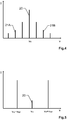
- the output radiation 11 - an example of which is shown in Figure 4 - has a frequency distribution with a carrier signal component 20 with respect to a carrier frequency ⁇ 0 and a plurality of sideband components.
- the intensity distribution I(v) generated by the carrier signal component 20 and the sidebands is typically symmetrical with respect to the intensity of the carrier signal component 20, which, as showed in the figure, may typically have the greatest intensity I.
- a first sideband component 21A provides for the first laser radiation and a different second sideband component 21B provides for the second laser radiation.
- At least a portion of the output radiation is fed to a delay line 14, so that a first local oscillator radiation 300A corresponding to the first laser radiation and a second local oscillator radiation 300B corresponding to the second laser radiation are generated and fed to a mixer 15. Furthermore, a portion of the first as well as a portion of the second laser radiation are emitted towards the target as a transmission beam comprising a first and a second transmission radiation 100A, 100B, respectively.
- the sideband components are arranged symmetrically about the carrier frequency ⁇ 0 as a function of the RF control frequency ⁇ RF of the control signal 13 of the Mach-Zehnder modulator 10.
- the sideband frequencies of the sideband components can thus each be derived from the control signal 13 of the Mach-Zehnder modulator 10.
- At least a portion of the first transmission radiation 100A and a portion of the second transmission radiation 100B returning from the target are received by a receiver (not shown) as the first and second reception radiation 200A,200B, respectively, and the mixer 15 is configured to generate a mixture of the first oscillator radiation 300A with the first reception radiation 200A and/or a mixture of the second oscillator radiation 300B with the second reception radiation 200B.
- the mixer 15 generates a beat signal with a beat frequency that is correlated with the propagation time of one of the transmitted signals 100A,100B. Based on the beat signal, the computing unit 16 of the distance measuring device can therefore derive a distance to the target.
- the generated control signal 13 of the electro-optical modulator 10 may already be sufficiently defined in order that the modulator 10 provides a desired well-defined frequency tuning characteristic.
- it is a benefit of the inventive distance measuring device that comparatively elaborate optical characterization and monitoring efforts in the context of the FMCW distance measurement can be relocated to a characterization and/or stabilization of the electronic control signal 13, i.e. wherein the control of the Mach-Zehnder modulator 10 is monitored electronically with low device complexity.
- part of the control signal 13 is fed via an RF coupler 17 to a sampling circuit 18 with an analogue-to-digital converter ("ADC"), by means of which a sampling of the control signal 13 is performed.
- ADC analogue-to-digital converter
- such a sampling enables detection of non-linearities in the generation of the control signal 13 which can be taken into account in a feedback loop for generating the control signal 13 and/or to compensate for a distance measurement error introduced by the electronics.
- a bias signal component may be impressed on the output signal of the signal generator 12, i.e. impressed on the control signal 13 driving the Mach-Zehnder modulator 10, such that the carrier signal 20 generated by the Mach-Zehnder modulator 10 is suppressed.
- This enables, as shown in Figure 5 , to increase the signal amplitudes of the sidebands 21 relative to the signal amplitude of the carrier signal component 20.
Description
- The invention relates to a distance measuring method for a distance measurement based on the principle of a modulated continuous wave radar, according to the preamble of
Claim 1 and a distance measuring device according to the preamble ofClaim 6. - In the field of electronic distance measurement different principles and methods are known. One approach involves emitting a transmission signal in the form of frequency-modulated electromagnetic radiation towards the target to be measured and subsequently receiving at least a part of the radiation returning from the target as a reception signal, also known as an echo or echo signal. The target to be measured can have both specular, for example, when retro-reflectors are used, and diffuse back-scattering characteristics.
- So called FMCW distance measuring devices (FMCW: "Frequency Modulated Continuous Wave radar"), also known as modulated continuous wave radar devices or FMCW radar devices, allow an absolute distance measurement to a target to be measured.
- After reception, the echo signal is superimposed/mixed with a local oscillator signal to generate a beat signal, this beat signal having a beat frequency which is correlated with the propagation time of the transmitted signal. Thus, based on the beat signal, the distance to the target can then be derived on the basis of the propagation time.
- In a FMCW arrangement, a tunable laser source is used, wherein, in what may be regarded in principle as the simplest embodiment, the variation in the tuning of the optical frequency of the laser source is linear and takes place with a known tuning rate. The reception signal is superimposed with a second signal, which is typically derived from the emitted signal, wherein the resulting beat frequency of the mixing product, the interferogram, is a measure of the distance to the target.
- Various variations of this basic form are known in the prior art. For example, a reference interferometer may be used to measure the tuning behaviour of the laser.
- The distance measuring devices used to implement these methods typically use a signal generator, which imposes a signal onto a modulatable radiation source. In the optical range, the radiation sources most commonly used are lasers or laser diodes. For emission and reception in the optical range an arrangement of transmitting and receiving lenses are used, wherein for reception a detector for heterodyne mixing may be used, followed by an A/D converter and a digital signal processor.
- The change in frequency of the emitted transmission signal represents the scale of the measurement. Depending on the accuracy requirements of the distance measurement, this scale can be verified or determined more precisely by means of an additional measurement. For example, a sufficiently linear continuous tuning of the laser source often requires additional complexity. For this purpose, for example, a part of the emitted radiation may be passed through a reference interferometer with a defined reference length. From the resulting beat product it is possible to infer the temporal change in frequency of the emitted transmission signal on the basis of the known reference length. If the reference length is not known or is unstable, e.g. due to temperature effects, it may be determined using an additional calibration unit, for example a gas cell or a Fabry-Perot-element.
- In the most favourable case, the target is at rest relative to the distance meter, i.e. the target has a time-invariant distance to the distance meter. However, with appropriate compensation measures absolute distance measurements are also feasible on moving or vibrating targets.
- A radial motion between the target and the distance meter gives rise to Doppler shifts in the beat frequency. However, the Doppler shifts can be compensated, e.g. by a combined measurement of an ascending frequency ramp followed by descending frequency ramp, because the Doppler shifts are the same for both ramps in case of a constant speed of the target, whereas the beat frequencies generated by the ramps have different signs.
- However, by using temporally successive opposing ramps, i.e with successive variations of the chirp sign, the usable measuring rate is also halved. In addition, this approach is based on the fact that a constant target speed applies during the traversal period for the two ramps. However, in practice this assumption of a constant speed often does not apply because accelerations and/or vibration of the target during the measurement process, speckle effects, or other effects give rise to non-negligible measuring fluctuations in the distance measurement.
- This problem may be eliminated by simultaneously using two opposing frequency ramps, wherein radiation with two radiation components is emitted. For example, the frequency of a first radiation component may be variably tuned "upwards", i.e. to higher frequencies, while at the same time, the frequency of a second radiation component is variably tuned "downwards", i.e. to lower frequencies. Therefore, the requirement for a constant relative radial velocity of the target is limited to a short time window. In addition, by using such so-called opposing chirps, a reduction in the measurement rate is also avoided.
- In order to be able to separate the radiation components for measurement purposes, various measures are known in the prior art, e.g. polarization-based, spectral-based, or algorithmic separations.
- In the prior art, the two components of the transmission radiation with opposite modulated signal frequencies are typically generated by means of two separate laser sources, for example, by means of two DFB lasers. However, the device complexity necessary for achieving two well defined transmission signals, particularly with respect to a desired tuning accuracy of each of the signals to provide the required well defined frequency difference between the two beams, is often disadvantageous. For example, using corresponding reference interferometers to characterize or monitor the frequency tuning of each beam may be conflicting with reducing technical effort.
-
US 6,573,982 B1 discloses to apply a double-sideband linear chirped waveform to a laser transmitter beam for frequency modulation, wherein one sideband is a frequency up-chirp and the other is a frequency down-chirp. - It is an object of the present invention to provide an improved FMCW distance measuring method and a corresponding distance meter.
- This object is achieved by realizing the features of the independent claim. Features which further develop the invention in an alternative or advantageous manner are described in the dependent patent claims.
- The invention relates to a FMCW (FMCW: frequency modulated continuous wave radar) distance measuring method comprising the generation of a first and a second laser radiation, wherein the first laser radiation has a first frequency modulation and the second laser radiation has a second frequency modulation, wherein at least in sections a time derivative of the first frequency modulation is different from a time derivative of the second frequency modulation.
- In other words, a time section of the first frequency modulation serving for an FMCW evaluation (FMCW: frequency modulated continuous wave radar) corresponds to a time section of the second frequency modulation serving for the FMCW evaluation, in particular the time sections being simultaneous to each other, wherein in each of the respective time sections corresponding to one another for the FMCW evaluation the first and second frequency modulation have different time derivatives.
- This is a generalization of the so-called opposing chirp method where the first and second frequency modulation are provided by two opposing frequency ramps, i.e. wherein in at least a section of the second frequency modulation the second frequency modulation has a modulation direction running in opposite direction compared to the modulation direction of the first frequency modulation in a corresponding section of the first frequency modulation, particularly wherein in the section of the second frequency modulation the second frequency modulation is exactly opposite, i.e. same value of the time derivative but different sign, to the first frequency modulation in the corresponding section of the first frequency modulation.
- Furthermore, the method comprises the steps: simultaneously emitting to a target at least part of the first laser radiation as a first transmission radiation and at least part of the second laser radiation as a second transmission radiation; receiving at least part of the first transmission radiation returning from the target as first reception radiation and at least part of the second transmission radiation returning from the target as second reception radiation; generating a first and a second mixed signal - the first mixed signal being based on mixing of the first reception radiation with a first local oscillator radiation and the second mixed signal being based on mixing the second reception radiation with a second local oscillator radiation - for a distance measurement in accordance with the principle of a modulated continuous wave radar; and determining at least one distance to the target based on the first and second mixed signal.
- For example, at least part of the first laser radiation and at least part of the second laser radiation is passed through a local oscillator stage in order to generate the first and second local oscillator radiation, i.e. the first and second mixed signals each represent a beat signal with a beat frequency that is correlated with the propagation time of the first or the second transmission radiation.
- Alternatively, the local oscillator radiation may also be generated by separate radiation sources.
- The first and the second mixed signal can be, for example, two separately-generated signals or the first and second mixed signal can be two different signal components of a common mixed signal, generated by a common mixing of the first laser radiation, the second laser radiation, the first received radiation, and the second received radiation.
- According to the present invention, generating the first and the second laser radiation comprises: generating a base radiation and modulating the base radiation with an electro-optical modulator, wherein the base radiation is passed through the electro-optical modulator and converted into an output radiation. For example, the electro-optical modulator may be an intensity modulator of the Mach-Zehnder type or a phase modulator.
- Due to the modulation by the electro-optical modulator, for a given control signal of the electro-optical modulator the output radiation has a carrier signal component with respect to a carrier frequency and a plurality of sideband components with respect to different sideband frequencies. According to the invention, a first sideband component, i.e. an arbitrary sideband of arbitrary order of the output radiation, provides for the first laser radiation and a second sideband component, i.e. an arbitrary sideband of arbitrary order of the output radiation, provides for the second laser radiation, wherein the second sideband component is different from the first sideband component.
- It goes without saying that also a first and a second (different) group of sideband components - respectively comprising the first and second sideband component, may respectively provide for the first and second laser radiation.
- A particular benefit of the inventive distance measuring method is a reduction of the device complexity for characterizing the frequency modulations of the two laser beams, in that comparatively elaborate optical characterization and monitoring efforts in the context of the FMCW distance measurement are relocated to a characterization and/or stabilization of the electronic control signal of the electro-optical modulator. In particular, with the inventive distance measuring method optical reference components, e.g. corresponding reference interferometers, which are typically required in the prior art to obtain a defined accuracy, can be largely dispensed with. In addition, for example, the long-term stability of a corresponding FMCW distance measuring device can be ensured with simple, in particular electronic, means.
- The electro-optical modulator may be controlled by a tunable RF control signal (radio frequency signal) with a variable RF-frequency, e.g. based on a voltage-controlled oscillator or a direct-digital-synthesizer, wherein the frequency of each of the individual side bands or the frequency difference between sidebands can be derived from the set RF-frequency, e.g. wherein the modulator typically provides the sidebands such that differences in sideband frequencies are integer multiples of the RF-frequency.
- Furthermore, the RF control signal of the electro-optical modulator may be further characterized in order to increase the accuracy or for monitoring purposes.
- For example, in accordance with one embodiment a reference signal is generated based on at least part of the control signal, a sampling of the reference signal is carried out, and the sampling is taken into account when determining the at least one distance to the target.
- By way of example, information from the sampling may be used to compensate for a distance measurement error introduced by the electronics and/or information from the sampling may be provided as feedback for stabilizing or controlling the generation of the control signal of the electro-optical modulator.
- According to a further embodiment, the control signal is generated based on an output signal of a signal generator, e.g. a voltage controlled oscillator or a direct-digital-synthesizer, wherein from the sampling a comparison parameter is determined by comparing the reference signal with a desired signal, e.g. the desired signal representing or being indicative of a theoretical control signal providing for a desired frequency tuning characteristics, and the output signal is adjusted based on the comparison parameter. Therefore, for example, age-related and/or temperature-induced faults/changes in the electronics can be detected.
- For example, in order to simplify the sampling, the reference signal may be transformed to lower frequencies prior to sampling.
- Accordingly, in accordance with a further embodiment, the reference signal is generated based on a transformation of at least part of the control signal, wherein the frequency of the reference signal is lower than the frequency of the control signal.
- In particular, it goes without saying that further signal processing means, e.g. such as an anti-aliasing filter, known in the art may be applied to further analyse and/or process the reference signal.
- In particular, according to a further embodiment, the control signal is configured in such a way that the carrier signal component is suppressed, in particular by impressing a bias signal component on the output signal of the signal generator, e.g. wherein the bias signal component is configured to attenuate the even harmonics of the electro-optical modulator.
- The invention also relates to a distance measuring device comprising a transmitter configured for emitting towards a target at least part of a first laser radiation as a first transmission radiation and at least part of a second laser radiation as a second transmission radiation, wherein the first laser radiation has a first frequency modulation, and the second laser radiation has a second frequency modulation, wherein at least in sections a time derivative of the first frequency modulation is different from a time derivative of the second frequency modulation. Furthermore, the distance measuring device comprises: a receiver unit configured for receiving at least part of the first transmission radiation returning from the target as first reception radiation and at least part of the second transmission radiation returning from the target as second reception radiation; a mixer unit configured for generating a first and a second mixed signal - the first mixed signal being based on mixing of the first reception radiation with a first local oscillator radiation and the second mixed signal being based on mixing the second reception radiation with a second local oscillator radiation - for providing a distance measurement in accordance with the principle of a modulated continuous wave radar; and a computing unit configured for determining at least one distance to the target based on the first and second mixed signal.
- Typically, the receiver unit and the mixer unit are provided by a single component. However, these units may also be provided by separate components.
- It goes without saying that the distance measuring device can also have other generic advantageous properties and components from the prior art for a distance measurement in accordance with the principle of a modulated continuous wave radar.
- For example, at least part of the first laser radiation and at least part of the second laser radiation is passed through a local oscillator stage in order to generate the first and second local oscillator radiation, i.e. the first and second mixed signals each represent a beat signal with a beat frequency that is correlated with the propagation time of the first or the second transmission radiation.
- Alternatively, the local oscillator radiation may also be generated by separate radiation sources.
- According to the present invention, the transmitter comprises a laser beam source configured for generating a base radiation and an electro-optical modulator, wherein the transmitter is configured in such a way that the base radiation is passed through the electro-optical modulator and is converted into an output radiation.
- Due to the modulation by means of the electro-optical modulator, for a given control signal of the electro-optical modulator the output radiation has a carrier signal component (with respect to a carrier frequency) and a plurality of sideband components (with respect to sideband frequencies), wherein, according to the invention, a first side band component, i.e. an arbitrary sideband of arbitrary order of the output radiation, provides for the first laser radiation and a second (different) side band component, i.e. an arbitrary sideband of arbitrary order of the output radiation, provides for the second laser radiation.
- In particular, the distance measuring device according to the invention is configured to carry out the distance measuring method described above.
- For example, in one embodiment the distance measuring device may be configured to carry out the FMCW distance measurement based on the so-called opposing chirp principle, i.e. wherein the distance measuring device is configured that in at least a section of the second frequency modulation the second frequency modulation has a modulation direction running in opposite direction compared to the modulation direction of the first frequency modulation in a corresponding section of the first frequency modulation, particularly wherein in the section of the second frequency modulation the second frequency modulation is exactly opposite to the first frequency modulation in the corresponding section of the first frequency modulation.
- According to a further embodiment, the distance measuring device has a coupling component, e.g. an RF power coupler, configured for feeding at least a first part of the control signal to a driver channel of the electro-optical modulator and for feeding at least a second part of the control signal to a reference channel. The reference channel has a sampling circuit, e.g. with an analogue-to-digital converter, configured for generating a reference signal based on the second part of the control signal and for carrying out a sampling of the reference signal, wherein the distance measuring device is configured to take the sampling into account for determining the at least one distance to the target.
- In a further embodiment the distance measuring device has a signal generator, e.g. a voltage-controlled oscillator or a direct-digital-synthesizer, and is configured for generating the control signal based on an output signal of the signal generator, to determine from the sampling a comparison parameter comparing the reference signal with a desired signal, e.g. the desired signal being indicative of a theoretical signal providing for a desired frequency tuning characteristics of the electro-optical modulator, and to adjust the control signal based on the comparison parameter.
- Thus the frequency sweep of the electro-optical modulator can be monitored/controlled, also called linearized, i.e. wherein the comparison parameter is used as feedback to the signal generator input signal in order to provide a frequency tuning of the electro-optical modulator which follows a given/desired course.
- In particular, according to a further embodiment, the sampling circuit has a transformation stage, e.g. having a RF-frequency divider, configured for transforming at least a portion of the second part of the control signal to a frequency which is lower than the frequency of the control signal.
- Furthermore, in accordance with another embodiment, the distance measuring device is configured to generate the control signal in such a way that the carrier signal component is suppressed, in particular wherein a bias signal component is impressed on the output signal of the signal generator, e.g. wherein the bias signal component is configured to attenuate the even harmonics of the electro-optical modulator.
- The method and distance measuring device according to the invention are described or explained in more detail below, purely by way of example, with reference to working examples shown schematically in the drawing. Identical elements are labelled with the same reference numerals in the figures. The described embodiments are generally not shown true to scale and they are also not to be interpreted as limiting the invention. Specifically,
- Fig. 1:
- representation of the time dependence of the transmission and reception frequency of a modulated continuous wave radar with ascending and descending frequency ramp;
- Fig. 2:
- transmission and reception frequency of a modulated continuous wave radar with opposing chirp;
- Fig. 3:
- schematic arrangement of components for a FMCW distance measuring device according to the invention;
- Fig. 4:
- example frequency distribution of the base radiation modulated with a Mach-Zehnder modulator;
- Fig. 5:
- schematic representation of a suppression of the carrier signal component by means of a bias signal component.
-
Figure 1 shows a schematic representation of the time dependence of the frequency of thetransmission radiation 1 and thereception radiation 2 of a modulated continuous wave radar with ascending and descending frequency ramp, also called an FMCW radar device, which enables an absolute distance measurement to a target to be measured. - Modulated electromagnetic radiation is emitted onto the target to be measured as a transmission signal and at least a portion of the radiation returning from the target is subsequently received as an echo signal. The target to be measured can have both specular and diffuse back-scattering characteristics. After reception, the echo signal is superimposed with a local oscillator signal to generate an interferogram, wherein from the interferogram the propagation time of the transmission signal and therefore the distance to the target can be derived, e.g. via a beat frequency correlated with the propagation time.
- The radiation generated by the FMCW distance measuring device is frequency-modulated by a signal generator, e.g. in such a way that in the temporal progression t of the signal frequency ν ascending and descending frequency ramps are generated. Typically, both an ascending and a descending frequency ramp are used in order to compensate for Doppler effects, because with only a single, e.g. ascending frequency ramp, measured frequency changes of the beat frequency cannot be uniquely assigned to a distance component or a velocity component of the target or distance measuring device.
- During the
propagation time 3 of the transmission signal to the target and back the frequency of the transmitter changes. Therefore, without taking into account the Doppler effect, a time-shiftedrepresentation 4 of the frequency-modulatedtransmission frequency 1 would be generated, whereas by taking into account the Doppler effect the time-shiftedrepresentation 4 of the frequency-modulatedtransmission frequency 1 is additionally shifted in frequency direction. The distance measurement is effected with respect to measuringranges 5 also shown in the figure for the ascending or the descending frequency ramp. - By using an ascending and a descending frequency ramp, e.g. by means of a triangular frequency modulation as shown in the figure, the Doppler frequency can be determined as a measure of a relative radial velocity of the target with respect to the measuring device, i.e. as an independent measurement variable in addition to the distance measurement.
- For example, if the target is moving radially away from the distance measuring device, then the frequency of the beat signal corresponding to the
ascending ramp 2 may decrease by the Doppler frequency such that thedifference frequency component 6 of the ascending ramp, i.e. the difference between thetransmission frequency 1 and thereception frequency 2 corresponding to the ascending ramp, is increased. By contrast, thedifference frequency component 7 of the descending ramp decreases. - Since at constant relative radial velocity between the target and the measuring device the frequency offset introduced by the Doppler effect is identical for the ascending and the descending ramp, then, given equal values of steepness of the frequency modulation in the ascending and the descending ramp, the mean value of the difference frequencies with respect to ascending and descending ramps is a measure of distance, independently of the relative radial velocity, whereas the sum of the difference frequencies is a measure of the relative radial velocity between the target and the measuring device.
- However, a temporal separation between transmitting the ascending and the descending frequency ramp requires that the relative radial velocity is constant during the distance measurement. In practice, however, this assumption is often not met and object vibrations, speckle effects or other effects which can interfere with the interferometric phase, can give rise to non-negligible fluctuations in the measured distance.
- Therefore, in prior art often FMCW distance measuring devices with so-called opposing chirp are used, i.e. wherein, for example by means of two laser beams, an ascending and a descending frequency ramp are essentially emitted at the same time. The assumption of a constant relative radial velocity then only needs to be satisfied within a short time window.
- In general, it is sufficient to use two frequency modulations, wherein at least in sections a time derivative of the first frequency modulation is different from a time derivative of the second frequency modulation.
-
Figure 2 shows a schematic representation of the transmission and reception frequency of a modulated continuous wave radar with so-called opposing chirp. In this case the radiation emitted onto a target has two components with different temporal variations of the signal frequency, i.e. opposing frequency ramps 1A,1B. - For example, the radiation components may be emitted as two overlapping laser beams with a phase offset of the opposing chirp of exactly 180°, hence strictly out of phase. The modulation depth of the two laser beams may be different. If both laser beams are emitted via a common lens towards a common target, or received by it, then it is required by measures on receiver side that two
reception signals - Again, analogous to
Fig. 1 , in order to illustrate the principle and the Doppler effect also the time-shiftedvirtual representations transmission frequencies - In analogy to using sequential frequency ramps as shown in
Fig. 1 , in the case of equal steepness of the frequency modulation in the ascending and the descending ramp, the mean value of thedifference frequencies - In the prior art, the two laser beams with oppositely modulated
transmission frequencies -
Figure 3 shows a schematic arrangement of the components for a FMCW distance measuring device according to the invention, wherein the two laser beam components are instead generated using the same laser beam source. - For example, the laser distance measuring device according to the invention has a
laser beam source 8, which generates abase radiation 9. Furthermore, the distance measuring device has a Mach-Zehnder modulator 10, wherein thebase radiation 9 is passed through the Mach-Zehnder modulator 10, and is thus converted into a modulatedoutput radiation 11, wherein the Mach-Zehnder modulator 10 is controlled using anoscillator signal 13 generated by asignal generator 12, e.g. a voltage-controlled oscillator or a direct-digital-synthesizer. - For a given
control signal 13 of the Mach-Zehnder modulator 10, the output radiation 11 - an example of which is shown inFigure 4 - has a frequency distribution with acarrier signal component 20 with respect to a carrier frequency ν0 and a plurality of sideband components. The intensity distribution I(v) generated by thecarrier signal component 20 and the sidebands is typically symmetrical with respect to the intensity of thecarrier signal component 20, which, as showed in the figure, may typically have the greatest intensity I. - According to the invention, a
first sideband component 21A provides for the first laser radiation and a differentsecond sideband component 21B provides for the second laser radiation. - For the FMCW distance measurement at least a portion of the output radiation is fed to a
delay line 14, so that a firstlocal oscillator radiation 300A corresponding to the first laser radiation and a secondlocal oscillator radiation 300B corresponding to the second laser radiation are generated and fed to amixer 15. Furthermore, a portion of the first as well as a portion of the second laser radiation are emitted towards the target as a transmission beam comprising a first and asecond transmission radiation - In terms of frequency, the sideband components, as schematically shown in
Figure 5 , are arranged symmetrically about the carrier frequency ν0 as a function of the RF control frequency νRF of thecontrol signal 13 of the Mach-Zehnder modulator 10. The sideband frequencies of the sideband components can thus each be derived from thecontrol signal 13 of the Mach-Zehnder modulator 10. - At least a portion of the
first transmission radiation 100A and a portion of thesecond transmission radiation 100B returning from the target are received by a receiver (not shown) as the first andsecond reception radiation mixer 15 is configured to generate a mixture of thefirst oscillator radiation 300A with thefirst reception radiation 200A and/or a mixture of thesecond oscillator radiation 300B with thesecond reception radiation 200B. For example, themixer 15 generates a beat signal with a beat frequency that is correlated with the propagation time of one of the transmitted signals 100A,100B. Based on the beat signal, thecomputing unit 16 of the distance measuring device can therefore derive a distance to the target. - Particularly when using a direct-digital-synthesizer as
signal generator 12, the generatedcontrol signal 13 of the electro-optical modulator 10 may already be sufficiently defined in order that themodulator 10 provides a desired well-defined frequency tuning characteristic. In any case, it is a benefit of the inventive distance measuring device that comparatively elaborate optical characterization and monitoring efforts in the context of the FMCW distance measurement can be relocated to a characterization and/or stabilization of theelectronic control signal 13, i.e. wherein the control of the Mach-Zehnder modulator 10 is monitored electronically with low device complexity. - For example, part of the
control signal 13 is fed via anRF coupler 17 to asampling circuit 18 with an analogue-to-digital converter ("ADC"), by means of which a sampling of thecontrol signal 13 is performed. In particular, such a sampling enables detection of non-linearities in the generation of thecontrol signal 13 which can be taken into account in a feedback loop for generating thecontrol signal 13 and/or to compensate for a distance measurement error introduced by the electronics. - In addition, a bias signal component may be impressed on the output signal of the
signal generator 12, i.e. impressed on thecontrol signal 13 driving the Mach-Zehnder modulator 10, such that thecarrier signal 20 generated by the Mach-Zehnder modulator 10 is suppressed. This enables, as shown inFigure 5 , to increase the signal amplitudes of the sidebands 21 relative to the signal amplitude of thecarrier signal component 20. - Although the invention is illustrated above, partly with reference to some preferred embodiments, it must be understood that numerous modifications and combinations of different features of the embodiments can be made. All of these modifications lie within the scope of the appended claims
Claims (10)
- Distance measuring method comprising• generating a first and a second laser radiation, whereino the first laser radiation has a first frequency modulation (1A), ando the second laser radiation has a second frequency modulation (1B), wherein at least in sections a time derivative of the first frequency modulation (1A) is different from a time derivative of the second frequency modulation (2A),• simultaneously emitting to a target at least part of the first laser radiation as a first transmission radiation (100A) and at least part of the second laser radiation as a second transmission radiation (100B),• receiving at least part of the first transmission radiation (100A) returning from the target as first reception radiation (200A) and at least part of the second transmission radiation (100B) returning from the target as second reception radiation (200B),• generating a first and a second mixed signal, the first mixed signal being based on mixing of the first reception radiation (200A) with a first local oscillator radiation (300A) and the second mixed signal being based on mixing the second reception radiation (200B) with a second local oscillator radiation (300B), for a distance measurement in accordance with the principle of a modulated continuous wave radar, and• determining at least one distance to the target based on the first and second mixed signal,wherein generating the first and the second laser radiation comprises• generating a base radiation (9), and• modulating the base radiation (9) with an electro-optical modulator (10), wherein the base radiation (9) is passed through the electro-optical modulator (10) and converted into an output radiation (11), namely wherein for a given control signal (13) of the electro-optical modulator (10) the output radiation (11) has a carrier signal component (20) and a plurality of sideband components,wherein• a first sideband component (21A) provides for the first laser radiation and• a second sideband component (21B) provides for the second laser radiation,characterized by• feeding at least a first part of the control signal (13) to a driver channel of the electro-optical modulator (10) and feeding at least a second part of the control signal (13) to a reference channel,• generating, by the reference channel, a reference signal based on the second part of the control signal (13),• carrying out a sampling of the reference signal, and• taking into account the sampling when determining the at least one distance to the target.
- Distance measuring method according to Claim 1,
characterized in that
in at least a section of the second frequency modulation the second frequency modulation (1B) has a modulation direction running in opposite direction compared to the modulation direction of the first frequency modulation (1A) in a corresponding section of the first frequency modulation, particularly wherein in the section of the second frequency modulation the second frequency modulation (1B) is exactly opposite to the first frequency modulation (1A) in the corresponding section of the first frequency modulation. - Distance measuring method according to Claim 1 or 2,
characterized in that
the control signal (13) is generated based on an output signal of a signal generator (12), wherein• from the sampling a comparison parameter is determined by comparing the reference signal with a desired signal, and• the output signal is adjusted based on the comparison parameter. - Distance measuring method according to any one of the preceding Claims ,
characterized in that
the reference signal is generated based on a transformation of at least part of the control signal, wherein the frequency of the reference signal is lower than the frequency of the control signal. - Distance measuring method according to any one of the preceding claims,
characterized in that
the control signal (13) is configured in such a way that the carrier signal component (20) is suppressed, in particular by impressing a bias signal component on the output signal of the signal generator (12). - Distance measuring device comprising• a transmitter configured for emitting towards a target at least part of a first laser radiation as a first transmission radiation (100A) and at least part of a second laser radiation as a second transmission radiation (100B), wherein∘ the first laser radiation has a first frequency modulation (1A), and∘ the second laser radiation has a second frequency, modulation (1B), wherein at least in sections a time derivative of the first frequency modulation (1A) is different from a time derivative of the second frequency modulation (1B)• a receiver unit configured for receiving at least part of the first transmission radiation (100A) returning from the target as first reception radiation (200A) and at least part of the second transmission radiation (100B) returning from the target as second reception radiation (200B),• a mixer unit (15) configured for generating a first and a second mixed signal, the first mixed signal being based on mixing of the first reception radiation (200A) with a first local oscillator radiation (300A) and the second mixed signal being based on mixing the second reception radiation (200B) with a second local oscillator radiation (300B), for providing a distance measurement in accordance with the principle of a modulated continuous wave radar, and• a computing unit (16) configured for determining at least one distance to the target based on the first and second mixed signal,wherein the transmitter comprises• a laser beam source (8) configured for generating a base radiation (9), and• an electro-optical modulator (10),wherein the transmitter is configured in such a way that• the base radiation (9) is passed through the electro-optical modulator (10) and is converted into an output radiation (11), namely wherein for a given control signal (13) of the electro-optical modulator (10) the output radiation (11) has a carrier signal component (20) and a plurality of sideband components,• a first sideband component (21A) provides for the first laser radiation, and• a second sideband component (21B) provides for the second laser radiationcharacterized in that• the distance measuring device has a coupling component (17) configured for feeding at least a first part of the control signal (13) to a driver channel of the electro-optical modulator (10) and for feeding at least a second part of the control signal (13) to a reference channel,• the reference channel has a sampling circuit (18), configured for generating a reference signal based on the second part of the control signal (13), and for carrying out a sampling of the reference signal, and• the distance measuring device is configured to take the sampling into account for determining the at least one distance to the target.
- Distance measuring device according to Claim 6,
characterized in that
the distance measuring device is configured that in at least a section of the second frequency modulation the second frequency modulation (1B) has a modulation direction running in opposite direction compared to the modulation direction of the first frequency modulation (1A) in a corresponding section of the first frequency modulation, particularly wherein in the section of the second frequency modulation the second frequency modulation (1B) is exactly opposite to the first frequency modulation (1A) in the corresponding section of the first frequency modulation. - Distance measuring device according to Claim 6 or 7,
characterized in that
the distance measuring device has a signal generator (12) and is configured• for generating the control signal (13) based on an output signal of the signal generator (12),• to determine from the sampling a comparison parameter comparing the reference signal with a desired signal, and• to adjust the output signal based on the comparison parameter. - Distance measuring device according to any one of Claims 6 to 8,
characterized in that
the sampling circuit (18) has a transformation stage, configured for transforming at least a portion of the second part of the control signal to a frequency which is lower than the frequency of the control signal (13). - Distance measuring device according to any one of Claims 6 to 9,
characterized in that
the distance measuring device is configured to generate the control signal (13) in such a way that the carrier signal component (20) is suppressed, in particular wherein a bias signal component is impressed on the output signal of the signal generator (12).
Priority Applications (3)
| Application Number | Priority Date | Filing Date | Title |
|---|---|---|---|
| EP18190343.6A EP3614170B1 (en) | 2018-08-22 | 2018-08-22 | Use of the sidebands of a mach-zehnder modulator for a fmcw distance measurement |
| CN201910771837.9A CN110857990B (en) | 2018-08-22 | 2019-08-21 | Distance measuring method and distance measuring device |
| US16/548,596 US11162773B2 (en) | 2018-08-22 | 2019-08-22 | Use of the sidebands of a mach-zehnder modulator for a FMCW distance measurement |
Applications Claiming Priority (1)
| Application Number | Priority Date | Filing Date | Title |
|---|---|---|---|
| EP18190343.6A EP3614170B1 (en) | 2018-08-22 | 2018-08-22 | Use of the sidebands of a mach-zehnder modulator for a fmcw distance measurement |
Publications (2)
| Publication Number | Publication Date |
|---|---|
| EP3614170A1 EP3614170A1 (en) | 2020-02-26 |
| EP3614170B1 true EP3614170B1 (en) | 2021-11-10 |
Family
ID=63364023
Family Applications (1)
| Application Number | Title | Priority Date | Filing Date |
|---|---|---|---|
| EP18190343.6A Active EP3614170B1 (en) | 2018-08-22 | 2018-08-22 | Use of the sidebands of a mach-zehnder modulator for a fmcw distance measurement |
Country Status (3)
| Country | Link |
|---|---|
| US (1) | US11162773B2 (en) |
| EP (1) | EP3614170B1 (en) |
| CN (1) | CN110857990B (en) |
Families Citing this family (5)
| Publication number | Priority date | Publication date | Assignee | Title |
|---|---|---|---|---|
| JP7478067B2 (en) | 2020-08-31 | 2024-05-02 | 株式会社ミツトヨ | Data correction device, measurement system, program, and correction method |
| US11709247B2 (en) * | 2020-09-22 | 2023-07-25 | Ay Dee Kay Llc | Fast chirp synthesis via segmented frequency shifting |
| CN114966619A (en) * | 2021-02-22 | 2022-08-30 | 华为技术有限公司 | Detection device, laser radar, chip and terminal equipment |
| WO2023118295A1 (en) * | 2021-12-23 | 2023-06-29 | Sony Semiconductor Solutions Corporation | Electronic device, method and computer program |
| CN114924281B (en) * | 2022-07-19 | 2022-11-04 | 天津大学四川创新研究院 | Based on H 13 C 14 Method and system for simultaneously measuring distance and speed of frequency modulated continuous waves of N gas pools |
Family Cites Families (9)
| Publication number | Priority date | Publication date | Assignee | Title |
|---|---|---|---|---|
| US4902125A (en) * | 1988-06-30 | 1990-02-20 | Raytheon Company | Optical system having beam amplification |
| US6573982B1 (en) * | 1991-09-18 | 2003-06-03 | Raytheon Company | Method and arrangement for compensating for frequency jitter in a laser radar system by utilizing double-sideband chirped modulator/demodulator system |
| DE19521771A1 (en) * | 1995-06-20 | 1997-01-02 | Jan Michael Mrosik | FMCW distance measuring method |
| EP1906137A1 (en) * | 2006-09-29 | 2008-04-02 | Leica Geosystems AG | Method and device for generating a synthetic wavelength |
| JP5752040B2 (en) * | 2008-09-11 | 2015-07-22 | ニコン・メトロロジー・エヌヴェ | Compact optical fiber arrangement for anti-chirp FMCW coherent laser radar |
| US9024809B2 (en) * | 2011-03-17 | 2015-05-05 | Sony Corporation | Object detection system and method |
| CN102866387B (en) * | 2012-10-16 | 2014-06-04 | 清华大学 | Millimeter wave frequency modulated continuous wave (FMCW) two-unit phased array distance and velocity measurement monolithic radar transceiver |
| CN103837870B (en) * | 2014-03-20 | 2016-01-20 | 华侨大学 | Continuous Wave with frequency modulation laser radar Nonlinear frequency modulation response coefficient measuring method |
| CN107505626B (en) * | 2017-09-12 | 2019-06-28 | 南京航空航天大学 | Laser measurement method and device based on double sideband modulation |
-
2018
- 2018-08-22 EP EP18190343.6A patent/EP3614170B1/en active Active
-
2019
- 2019-08-21 CN CN201910771837.9A patent/CN110857990B/en active Active
- 2019-08-22 US US16/548,596 patent/US11162773B2/en active Active
Also Published As
| Publication number | Publication date |
|---|---|
| US20200064116A1 (en) | 2020-02-27 |
| US11162773B2 (en) | 2021-11-02 |
| EP3614170A1 (en) | 2020-02-26 |
| CN110857990A (en) | 2020-03-03 |
| CN110857990B (en) | 2023-05-05 |
Similar Documents
| Publication | Publication Date | Title |
|---|---|---|
| EP3614170B1 (en) | Use of the sidebands of a mach-zehnder modulator for a fmcw distance measurement | |
| US7345744B2 (en) | Optical delay line to correct phase errors in coherent ladar | |
| US8823583B2 (en) | Radar sensor having two oscillators, two I/Q transmit mixers, and two I/Q receive mixers | |
| AU2009266432B2 (en) | Interferometric distance measuring method with spectrally separable double chirp and device | |
| US20210405194A1 (en) | Optical measurement device and measurement method | |
| US11719817B2 (en) | Distance-measuring apparatus and control method | |
| JPH06281741A (en) | Linear frequency modulation controller for fm laser radar | |
| CN102047071A (en) | Interferometric distance-measuring method with delayed chirp signal and such an apparatus | |
| JP7291385B2 (en) | Optical measuring device and measuring method | |
| KR101239166B1 (en) | Frequency modulated continuous wave proximity sensor | |
| WO2022095169A1 (en) | Frequency modulated continuous wave laser radar | |
| US10634788B2 (en) | Dual-beam FMCW distance measuring method having compensation of a velocity-dependent distance measurement error | |
| Grimaldi et al. | Analysis of spurs impact in PLL-based FMCW radar systems | |
| JP3307153B2 (en) | Laser radar device | |
| WO2018164110A1 (en) | Electromagnetic wave measurement apparatus and electromagnetic wave measurement method | |
| JP3262311B2 (en) | Frequency sweep error detection method and circuit, optical frequency sweep light source, and optical frequency domain reflection measurement circuit | |
| JP3510517B2 (en) | Optical frequency linear sweep device and modulation correction data recording device for optical frequency linear sweep device | |
| US20220317299A1 (en) | Distance measuring device | |
| CN115015953B (en) | Microwave-driven FMCW laser radar detection device and detection method thereof | |
| KR20200006060A (en) | Phase noise compensation method and apparatus | |
| GB2547551A (en) | An electronic circuit | |
| US8270844B2 (en) | Low jitter RF distribution system | |
| Gao et al. | Low phase noise coherent transceiver front-end for X-band multichannel chirped radar based on phase-synchronous optoelectronic oscillator | |
| Li et al. | Dual-chirp waveform generation and its TBWP improvement based on polarization modulation and phase coding | |
| Meena et al. | Mathematical Analysis and Modelling of a Novel Photonic based FMCW Signal Generation for Long Range Radar Applications |
Legal Events
| Date | Code | Title | Description |
|---|---|---|---|
| PUAI | Public reference made under article 153(3) epc to a published international application that has entered the european phase |
Free format text: ORIGINAL CODE: 0009012 |
|
| STAA | Information on the status of an ep patent application or granted ep patent |
Free format text: STATUS: THE APPLICATION HAS BEEN PUBLISHED |
|
| AK | Designated contracting states |
Kind code of ref document: A1 Designated state(s): AL AT BE BG CH CY CZ DE DK EE ES FI FR GB GR HR HU IE IS IT LI LT LU LV MC MK MT NL NO PL PT RO RS SE SI SK SM TR |
|
| AX | Request for extension of the european patent |
Extension state: BA ME |
|
| STAA | Information on the status of an ep patent application or granted ep patent |
Free format text: STATUS: REQUEST FOR EXAMINATION WAS MADE |
|
| 17P | Request for examination filed |
Effective date: 20200420 |
|
| RBV | Designated contracting states (corrected) |
Designated state(s): AL AT BE BG CH CY CZ DE DK EE ES FI FR GB GR HR HU IE IS IT LI LT LU LV MC MK MT NL NO PL PT RO RS SE SI SK SM TR |
|
| RIN1 | Information on inventor provided before grant (corrected) |
Inventor name: LE FLOCH, SEBASTIEN Inventor name: SALVADE, YVES Inventor name: ROHNER, MARCEL |
|
| REG | Reference to a national code |
Ref country code: DE Ref legal event code: R079 Ref document number: 602018026360 Country of ref document: DE Free format text: PREVIOUS MAIN CLASS: G01S0007491000 Ipc: G01S0007491100 |
|
| GRAP | Despatch of communication of intention to grant a patent |
Free format text: ORIGINAL CODE: EPIDOSNIGR1 |
|
| STAA | Information on the status of an ep patent application or granted ep patent |
Free format text: STATUS: GRANT OF PATENT IS INTENDED |
|
| RIC1 | Information provided on ipc code assigned before grant |
Ipc: G01S 7/4911 20200101AFI20210601BHEP Ipc: G01S 7/4912 20200101ALI20210601BHEP Ipc: G01S 17/32 20200101ALI20210601BHEP Ipc: G01S 17/34 20200101ALI20210601BHEP Ipc: G01B 9/02 20060101ALI20210601BHEP |
|
| INTG | Intention to grant announced |
Effective date: 20210616 |
|
| GRAS | Grant fee paid |
Free format text: ORIGINAL CODE: EPIDOSNIGR3 |
|
| GRAA | (expected) grant |
Free format text: ORIGINAL CODE: 0009210 |
|
| STAA | Information on the status of an ep patent application or granted ep patent |
Free format text: STATUS: THE PATENT HAS BEEN GRANTED |
|
| AK | Designated contracting states |
Kind code of ref document: B1 Designated state(s): AL AT BE BG CH CY CZ DE DK EE ES FI FR GB GR HR HU IE IS IT LI LT LU LV MC MK MT NL NO PL PT RO RS SE SI SK SM TR |
|
| REG | Reference to a national code |
Ref country code: GB Ref legal event code: FG4D |
|
| REG | Reference to a national code |
Ref country code: AT Ref legal event code: REF Ref document number: 1446571 Country of ref document: AT Kind code of ref document: T Effective date: 20211115 Ref country code: CH Ref legal event code: EP |
|
| REG | Reference to a national code |
Ref country code: DE Ref legal event code: R096 Ref document number: 602018026360 Country of ref document: DE |
|
| REG | Reference to a national code |
Ref country code: IE Ref legal event code: FG4D |
|
| REG | Reference to a national code |
Ref country code: LT Ref legal event code: MG9D |
|
| REG | Reference to a national code |
Ref country code: NL Ref legal event code: MP Effective date: 20211110 |
|
| REG | Reference to a national code |
Ref country code: AT Ref legal event code: MK05 Ref document number: 1446571 Country of ref document: AT Kind code of ref document: T Effective date: 20211110 |
|
| PG25 | Lapsed in a contracting state [announced via postgrant information from national office to epo] |
Ref country code: RS Free format text: LAPSE BECAUSE OF FAILURE TO SUBMIT A TRANSLATION OF THE DESCRIPTION OR TO PAY THE FEE WITHIN THE PRESCRIBED TIME-LIMIT Effective date: 20211110 Ref country code: LT Free format text: LAPSE BECAUSE OF FAILURE TO SUBMIT A TRANSLATION OF THE DESCRIPTION OR TO PAY THE FEE WITHIN THE PRESCRIBED TIME-LIMIT Effective date: 20211110 Ref country code: FI Free format text: LAPSE BECAUSE OF FAILURE TO SUBMIT A TRANSLATION OF THE DESCRIPTION OR TO PAY THE FEE WITHIN THE PRESCRIBED TIME-LIMIT Effective date: 20211110 Ref country code: BG Free format text: LAPSE BECAUSE OF FAILURE TO SUBMIT A TRANSLATION OF THE DESCRIPTION OR TO PAY THE FEE WITHIN THE PRESCRIBED TIME-LIMIT Effective date: 20220210 Ref country code: AT Free format text: LAPSE BECAUSE OF FAILURE TO SUBMIT A TRANSLATION OF THE DESCRIPTION OR TO PAY THE FEE WITHIN THE PRESCRIBED TIME-LIMIT Effective date: 20211110 |
|
| PG25 | Lapsed in a contracting state [announced via postgrant information from national office to epo] |
Ref country code: IS Free format text: LAPSE BECAUSE OF FAILURE TO SUBMIT A TRANSLATION OF THE DESCRIPTION OR TO PAY THE FEE WITHIN THE PRESCRIBED TIME-LIMIT Effective date: 20220310 Ref country code: SE Free format text: LAPSE BECAUSE OF FAILURE TO SUBMIT A TRANSLATION OF THE DESCRIPTION OR TO PAY THE FEE WITHIN THE PRESCRIBED TIME-LIMIT Effective date: 20211110 Ref country code: PT Free format text: LAPSE BECAUSE OF FAILURE TO SUBMIT A TRANSLATION OF THE DESCRIPTION OR TO PAY THE FEE WITHIN THE PRESCRIBED TIME-LIMIT Effective date: 20220310 Ref country code: PL Free format text: LAPSE BECAUSE OF FAILURE TO SUBMIT A TRANSLATION OF THE DESCRIPTION OR TO PAY THE FEE WITHIN THE PRESCRIBED TIME-LIMIT Effective date: 20211110 Ref country code: NO Free format text: LAPSE BECAUSE OF FAILURE TO SUBMIT A TRANSLATION OF THE DESCRIPTION OR TO PAY THE FEE WITHIN THE PRESCRIBED TIME-LIMIT Effective date: 20220210 Ref country code: NL Free format text: LAPSE BECAUSE OF FAILURE TO SUBMIT A TRANSLATION OF THE DESCRIPTION OR TO PAY THE FEE WITHIN THE PRESCRIBED TIME-LIMIT Effective date: 20211110 Ref country code: LV Free format text: LAPSE BECAUSE OF FAILURE TO SUBMIT A TRANSLATION OF THE DESCRIPTION OR TO PAY THE FEE WITHIN THE PRESCRIBED TIME-LIMIT Effective date: 20211110 Ref country code: HR Free format text: LAPSE BECAUSE OF FAILURE TO SUBMIT A TRANSLATION OF THE DESCRIPTION OR TO PAY THE FEE WITHIN THE PRESCRIBED TIME-LIMIT Effective date: 20211110 Ref country code: GR Free format text: LAPSE BECAUSE OF FAILURE TO SUBMIT A TRANSLATION OF THE DESCRIPTION OR TO PAY THE FEE WITHIN THE PRESCRIBED TIME-LIMIT Effective date: 20220211 Ref country code: ES Free format text: LAPSE BECAUSE OF FAILURE TO SUBMIT A TRANSLATION OF THE DESCRIPTION OR TO PAY THE FEE WITHIN THE PRESCRIBED TIME-LIMIT Effective date: 20211110 |
|
| PG25 | Lapsed in a contracting state [announced via postgrant information from national office to epo] |
Ref country code: SM Free format text: LAPSE BECAUSE OF FAILURE TO SUBMIT A TRANSLATION OF THE DESCRIPTION OR TO PAY THE FEE WITHIN THE PRESCRIBED TIME-LIMIT Effective date: 20211110 Ref country code: SK Free format text: LAPSE BECAUSE OF FAILURE TO SUBMIT A TRANSLATION OF THE DESCRIPTION OR TO PAY THE FEE WITHIN THE PRESCRIBED TIME-LIMIT Effective date: 20211110 Ref country code: RO Free format text: LAPSE BECAUSE OF FAILURE TO SUBMIT A TRANSLATION OF THE DESCRIPTION OR TO PAY THE FEE WITHIN THE PRESCRIBED TIME-LIMIT Effective date: 20211110 Ref country code: EE Free format text: LAPSE BECAUSE OF FAILURE TO SUBMIT A TRANSLATION OF THE DESCRIPTION OR TO PAY THE FEE WITHIN THE PRESCRIBED TIME-LIMIT Effective date: 20211110 Ref country code: DK Free format text: LAPSE BECAUSE OF FAILURE TO SUBMIT A TRANSLATION OF THE DESCRIPTION OR TO PAY THE FEE WITHIN THE PRESCRIBED TIME-LIMIT Effective date: 20211110 Ref country code: CZ Free format text: LAPSE BECAUSE OF FAILURE TO SUBMIT A TRANSLATION OF THE DESCRIPTION OR TO PAY THE FEE WITHIN THE PRESCRIBED TIME-LIMIT Effective date: 20211110 |
|
| REG | Reference to a national code |
Ref country code: DE Ref legal event code: R097 Ref document number: 602018026360 Country of ref document: DE |
|
| PLBE | No opposition filed within time limit |
Free format text: ORIGINAL CODE: 0009261 |
|
| STAA | Information on the status of an ep patent application or granted ep patent |
Free format text: STATUS: NO OPPOSITION FILED WITHIN TIME LIMIT |
|
| 26N | No opposition filed |
Effective date: 20220811 |
|
| PG25 | Lapsed in a contracting state [announced via postgrant information from national office to epo] |
Ref country code: AL Free format text: LAPSE BECAUSE OF FAILURE TO SUBMIT A TRANSLATION OF THE DESCRIPTION OR TO PAY THE FEE WITHIN THE PRESCRIBED TIME-LIMIT Effective date: 20211110 |
|
| PG25 | Lapsed in a contracting state [announced via postgrant information from national office to epo] |
Ref country code: SI Free format text: LAPSE BECAUSE OF FAILURE TO SUBMIT A TRANSLATION OF THE DESCRIPTION OR TO PAY THE FEE WITHIN THE PRESCRIBED TIME-LIMIT Effective date: 20211110 |
|
| PG25 | Lapsed in a contracting state [announced via postgrant information from national office to epo] |
Ref country code: MC Free format text: LAPSE BECAUSE OF FAILURE TO SUBMIT A TRANSLATION OF THE DESCRIPTION OR TO PAY THE FEE WITHIN THE PRESCRIBED TIME-LIMIT Effective date: 20211110 |
|
| REG | Reference to a national code |
Ref country code: CH Ref legal event code: PL |
|
| PG25 | Lapsed in a contracting state [announced via postgrant information from national office to epo] |
Ref country code: LU Free format text: LAPSE BECAUSE OF NON-PAYMENT OF DUE FEES Effective date: 20220822 Ref country code: LI Free format text: LAPSE BECAUSE OF NON-PAYMENT OF DUE FEES Effective date: 20220831 Ref country code: CH Free format text: LAPSE BECAUSE OF NON-PAYMENT OF DUE FEES Effective date: 20220831 |
|
| REG | Reference to a national code |
Ref country code: BE Ref legal event code: MM Effective date: 20220831 |
|
| PG25 | Lapsed in a contracting state [announced via postgrant information from national office to epo] |
Ref country code: IT Free format text: LAPSE BECAUSE OF FAILURE TO SUBMIT A TRANSLATION OF THE DESCRIPTION OR TO PAY THE FEE WITHIN THE PRESCRIBED TIME-LIMIT Effective date: 20211110 |
|
| PG25 | Lapsed in a contracting state [announced via postgrant information from national office to epo] |
Ref country code: IE Free format text: LAPSE BECAUSE OF NON-PAYMENT OF DUE FEES Effective date: 20220822 |
|
| PG25 | Lapsed in a contracting state [announced via postgrant information from national office to epo] |
Ref country code: BE Free format text: LAPSE BECAUSE OF NON-PAYMENT OF DUE FEES Effective date: 20220831 |
|
| PGFP | Annual fee paid to national office [announced via postgrant information from national office to epo] |
Ref country code: GB Payment date: 20230822 Year of fee payment: 6 |
|
| PGFP | Annual fee paid to national office [announced via postgrant information from national office to epo] |
Ref country code: FR Payment date: 20230828 Year of fee payment: 6 Ref country code: DE Payment date: 20230821 Year of fee payment: 6 |
|
| PG25 | Lapsed in a contracting state [announced via postgrant information from national office to epo] |
Ref country code: HU Free format text: LAPSE BECAUSE OF FAILURE TO SUBMIT A TRANSLATION OF THE DESCRIPTION OR TO PAY THE FEE WITHIN THE PRESCRIBED TIME-LIMIT; INVALID AB INITIO Effective date: 20180822 |
|
| PG25 | Lapsed in a contracting state [announced via postgrant information from national office to epo] |
Ref country code: CY Free format text: LAPSE BECAUSE OF FAILURE TO SUBMIT A TRANSLATION OF THE DESCRIPTION OR TO PAY THE FEE WITHIN THE PRESCRIBED TIME-LIMIT Effective date: 20211110 |