EP3609088A1 - Techniques for analog beamforming - Google Patents
Techniques for analog beamforming Download PDFInfo
- Publication number
- EP3609088A1 EP3609088A1 EP18187481.9A EP18187481A EP3609088A1 EP 3609088 A1 EP3609088 A1 EP 3609088A1 EP 18187481 A EP18187481 A EP 18187481A EP 3609088 A1 EP3609088 A1 EP 3609088A1
- Authority
- EP
- European Patent Office
- Prior art keywords
- sub
- code
- word
- antenna array
- array circuitry
- Prior art date
- Legal status (The legal status is an assumption and is not a legal conclusion. Google has not performed a legal analysis and makes no representation as to the accuracy of the status listed.)
- Withdrawn
Links
Images


Classifications
-
- H—ELECTRICITY
- H04—ELECTRIC COMMUNICATION TECHNIQUE
- H04B—TRANSMISSION
- H04B7/00—Radio transmission systems, i.e. using radiation field
- H04B7/02—Diversity systems; Multi-antenna system, i.e. transmission or reception using multiple antennas
- H04B7/04—Diversity systems; Multi-antenna system, i.e. transmission or reception using multiple antennas using two or more spaced independent antennas
- H04B7/08—Diversity systems; Multi-antenna system, i.e. transmission or reception using multiple antennas using two or more spaced independent antennas at the receiving station
-
- H—ELECTRICITY
- H04—ELECTRIC COMMUNICATION TECHNIQUE
- H04B—TRANSMISSION
- H04B7/00—Radio transmission systems, i.e. using radiation field
- H04B7/02—Diversity systems; Multi-antenna system, i.e. transmission or reception using multiple antennas
- H04B7/04—Diversity systems; Multi-antenna system, i.e. transmission or reception using multiple antennas using two or more spaced independent antennas
- H04B7/06—Diversity systems; Multi-antenna system, i.e. transmission or reception using multiple antennas using two or more spaced independent antennas at the transmitting station
- H04B7/0686—Hybrid systems, i.e. switching and simultaneous transmission
- H04B7/0695—Hybrid systems, i.e. switching and simultaneous transmission using beam selection
-
- H—ELECTRICITY
- H04—ELECTRIC COMMUNICATION TECHNIQUE
- H04B—TRANSMISSION
- H04B7/00—Radio transmission systems, i.e. using radiation field
- H04B7/02—Diversity systems; Multi-antenna system, i.e. transmission or reception using multiple antennas
- H04B7/04—Diversity systems; Multi-antenna system, i.e. transmission or reception using multiple antennas using two or more spaced independent antennas
- H04B7/06—Diversity systems; Multi-antenna system, i.e. transmission or reception using multiple antennas using two or more spaced independent antennas at the transmitting station
- H04B7/0613—Diversity systems; Multi-antenna system, i.e. transmission or reception using multiple antennas using two or more spaced independent antennas at the transmitting station using simultaneous transmission
- H04B7/0615—Diversity systems; Multi-antenna system, i.e. transmission or reception using multiple antennas using two or more spaced independent antennas at the transmitting station using simultaneous transmission of weighted versions of same signal
- H04B7/0617—Diversity systems; Multi-antenna system, i.e. transmission or reception using multiple antennas using two or more spaced independent antennas at the transmitting station using simultaneous transmission of weighted versions of same signal for beam forming
-
- H—ELECTRICITY
- H04—ELECTRIC COMMUNICATION TECHNIQUE
- H04B—TRANSMISSION
- H04B7/00—Radio transmission systems, i.e. using radiation field
- H04B7/02—Diversity systems; Multi-antenna system, i.e. transmission or reception using multiple antennas
- H04B7/04—Diversity systems; Multi-antenna system, i.e. transmission or reception using multiple antennas using two or more spaced independent antennas
- H04B7/08—Diversity systems; Multi-antenna system, i.e. transmission or reception using multiple antennas using two or more spaced independent antennas at the receiving station
- H04B7/0868—Hybrid systems, i.e. switching and combining
- H04B7/088—Hybrid systems, i.e. switching and combining using beam selection
Definitions
- the disclosure relates to techniques for analog beamforming applicable in 5G NR mmWave communications, in particular an antenna array circuitry and a user equipment (UE) circuit comprising such antenna array circuitry.
- the disclosure further relates to devices and methods of dynamical multi-beam superposition with adaptive gain split within single antenna array and their applications for UE performance optimizations in 5G NR mmWave communications.
- Analog beam forming is one major feature introduced by 5G NR mmWave communications 100 as exemplarily shown in Fig. 1 where UE 110 communicates with serving gNB 120 by forming one or more antenna beams 101, 102, 103 which may be distorted by signals from interfering gNB 130.
- Analog beamforming is achieved by antenna arrays (also named as antenna panels).
- antenna arrays also named as antenna panels.
- H/V beams have dependency with each other, e.g. V/H beams need to provide UE the antenna diversity for MIMO operations, so they cannot be in totally different directions.
- a corresponding device configured to perform the method and vice versa.
- a corresponding device may include a unit to perform the described method step, even if such a unit is not explicitly described or illustrated in the figures.
- the features of the various exemplary aspects described herein may be combined with each other, unless specifically noted otherwise.
- the techniques described herein may be implemented in wireless communication networks, in particular communication networks based on mobile communication standards such as 5G new radio (NR), in particular for millimeter-wave data rate.
- the techniques may also be applied in LTE networks, in particular LTE-A and/or OFDM and successor standards.
- the methods are also applicable for high speed communication standards from the 802.11 family according to the WiFi alliance, e.g. 802.11ad and successor standards.
- the methods and devices described below may be implemented in electronic devices such as cellular handsets and mobile or wireless devices or User Equipment communicating with access points and/or base stations.
- the described devices may include integrated circuits and/or passives and may be manufactured according to various technologies.
- the circuits may be designed as logic integrated circuits, ASICs, analog integrated circuits, mixed signal integrated circuits, optical circuits, memory circuits and/or integrated passives.
- antenna arrays e.g. antenna arrays that may be represented by the antenna array model 200 for UE RX analog beamforming shown in Fig. 2 and/or the antenna model 900 for UE RX analog beamforming shown in Fig. 9 .
- N is the number of antenna elements 211, 221, 231 within one antenna array 200.
- a fundamental concept of the disclosure presented in the following is to generate multiple beams (i.e. more than one) that work independently, while collaborate concurrently and simultaneously, with one another in covering different directions or angles at the same time by a single antenna array.
- the UE can at the same time test other candidate beams (e.g. RX beam sweeping) or apply measurement of intra-frequency neighboring cells in different beam directions without interrupting the DL PDSCH demodulation.
- the interference beam can be nulled in UE receiver side without degrading beam coverage from the serving cell.
- a method to dynamically superpose a set of pre-optimized sub-beams within one antenna array dynamically selects and maps a set of pre-optimized code-words into a new code-word, where each pre-optimized code-word is associated with a pre-optimized narrow sub-beam in a different direction.
- the mapping is performed in such a way that the beam formed by the new code-word is equivalent with analog superposition of those sub-beams.
- the mapping not only considers phase per antenna element but also optionally the gains. Furthermore, consider the total gain per antenna array is limited, the proposed mapping method supports to split different gains for different sub-beams so that trade-off between different sub-beams can be made (e.g.
- a first sub-method is to dynamically superpose a sweeping UE RX sub-beam on top of a constant UE RX sub-beam in a same antenna array, so that UE can apply NR serving cell PDSCH demodulation and NR UE beam sweeping (e.g. CSI-RS based serving beam tracking or SSB based neighboring cell measurement) at the same time without interrupting serving cell DL PDSCH demodulation.
- NR serving cell PDSCH demodulation e.g. CSI-RS based serving beam tracking or SSB based neighboring cell measurement
- the gains can be dynamically split among superposed sub-beams, so that inter-beam interference can be run-time controlled. The split may be based on the run-time channel quality measurement of each sub-beam. Remind that gain splitting is supported by the presented algorithm (see formula (8.1) and formula (8.2)).
- this sub-method can be extended to dynamically generate two UE RX sub-beams at the same time in different directions from single antenna array, where one sub-beam is for NR PDSCH reception and another sub-beam is for NR PDCCH reception.
- This is extremely helpful in case PDSCH beam and a different PDCCH beam are scheduled by gNB to be FDMed but in the same OFDM symbols.
- this is still a valid corner case. The method avoids DL demodulation performance drop in UE side in such corner case when the UE has only one activated antenna array at a time.
- a second sub-method is to null a narrow neighboring cell beam which is partially overlapping with a serving cell beam. It is done by first detecting the narrow interference beam through UR RX beam sweeping, and then superpose multiple narrow beams within the coverage of serving cell beam but not in the coverage of the narrow interference beam.
- the disclosed method significantly reduces the number of per-optimized code-words before product development because only a set of per-optimized code-words reflecting a set of basic sub-beams need to be stored. Run-time superposition of those basic sub-beams can make UE adapted to different scenarios: e.g. superposition of a couple of neighboring narrow beams leads to a wider beam. This reduces the code-word memory and also significantly reduces the lab characterization time for pre-optimized code-words.
- the sub-beams which are superposed are fully synchronized, so the final formed beam after superposition has little inter-beam impairments compared with concurrent multiple antenna array operations which are not perfectly synchronized. This is especially important for UE TX operation which needs strictly time synchronization among TX beams, otherwise the finally formed TX beam can be totally different than expectation.
- synchronization signal blocks may be used.
- the objective of initial cell search is to find a strong cell for potential connection, obtain an estimate of frame timing, obtain cell identifications and find reference signals for demodulation.
- PSS Primary Synchronization Signals
- SSS Secondary Synchronization Signals
- PSS and SSS are transmitted in synchronization signal blocks together with the Physical Broadcast Channel (PBCH).
- PBCH Physical Broadcast Channel
- the blocks are transmitted per slot at a fixed slot location.
- the UE correlates received signals and synchronization signal sequences by means of matched filters and performs the following steps: 1. Find Primary Sync Sequence and obtain symbol and frame timing.
- PBCH Physical Broadcast Channel
- Fig. 2 is a block diagram illustrating an antenna array 200 for UE RX analog beamforming according to the disclosure.
- the antenna array can be implemented by an antenna array circuitry or generally speaking by an antenna array device.
- the antenna array circuitry may be part of a radio frequency circuitry, e.g. an RF circuitry of a user equipment.
- the antenna array circuitry may be used for receiving and processing antenna signals from multiple antenna elements.
- the antenna array 200 can be used for analog beamforming in both RX and TX direction.
- the antenna array 200 comprises a plurality of antenna elements 211, 221, 231.
- Each antenna element 211, 221, 231 is configured to receive a respective analog signal 210, 220, 230 (r(1,t), r(2,t), r(N,t)).
- the antenna elements 211, 221, 231 are adjustable based on a code-word 212, 222, 232 which comprises respective phase configurations ⁇ p (1), ⁇ p (2), ⁇ p (N) of the plurality of antenna elements 211, 221, 231.
- the code-word is based on a superposition of a predetermined set of basic code-words. Each basic code-word associates with a corresponding sub-beam. A main radiation lobe of the predetermined sub-beam points in a predefined spatial direction.
- the antenna elements 211, 221, 231 may be configured to receive analog signals in a millimeter wave band.
- the code-word may comprise respective gain configurations g p (1), g p (2), g p (N) of the plurality of antenna elements 211, 221, 231.
- the antenna array 200 further comprises a plurality of weighting elements 213, 223, 233 to apply the code-word 212, 222, 232 to the plurality of antenna elements 211, 221, 231.
- the antenna array 200 further comprises an analog adder 240 configured to add outputs of the plurality of antenna elements 211, 221, 231 weighted by the respective weighting elements 213, 223, 233 to form a composite beam s(t) 241 which may be passed through an analog-to-digital converter 250 to provide a digital representation of s(t).
- an analog adder 240 configured to add outputs of the plurality of antenna elements 211, 221, 231 weighted by the respective weighting elements 213, 223, 233 to form a composite beam s(t) 241 which may be passed through an analog-to-digital converter 250 to provide a digital representation of s(t).
- formula (2) needs M*N separated phase shifters and a big analogy combiner per antenna array, which has huge HW costs. So the native superposition approach in formula (2) is NOT desired.
- the newly calculated code-word in (7.1) and (7.2) ( ⁇ ' ( k ) and optionally g' ( k ) in case the gains per antenna element is assumed to be different) exactly represents the new beam which is the analog superposition of M sub-beams.
- the newly calculated code-word can be programmed as normal code-word in the normal antenna array HW.
- formula (7.1)/(7.2) and (8.1)/(8.2) can be approximated by a look up tables or polynomial approximations by DSP FW, without additional HW changes.
- the overall computation load is also very low because the computation is required during UE beam-reconfigurations (semi-statistically).
- the computation complexity scales with number of antenna element N which is also very low: typical values for N in a UE antenna array is 4, 8, 12 or 16. Therefore the proposed method is very practical to be implemented in a real UE modem product.
- the disclosed method becomes efficient if the sub-beams to be superposed are carefully selected, which have as less overlapping as possible to avoid cross-talk. Therefore, narrow pre-optimized sub-beams with good directivity are preferred. Sometimes overlapped side-lobes cannot be avoided but usually they are 10dB lower than main lobe and the performance impact is minor.
- the antenna array 200 in Fig. 2 was modeled by Matlab.
- a tool was implemented to visualize the steered beams from the model.
- the disclosed multi-beam superposition method was implemented in the simulation environment to prove the concepts. In the following example the simulation results of the superposition of 2 beams are shown with different directions using the disclosed method.
- the simulation is based on a 1D Antenna array model with 16 antenna elements. Two sub-beams pointing to different directions (-30° and 60°) are to be superposed. The corresponding code-words of the two sub-beams are shown in Table 1 and Table 2. Table 1. Code-word for sub-beam 1: -30° Phase / ⁇ 0 0.5 1 1.5 0 0.5 1 1.5 Gain / 1 0.0338 0.1305 0.2771 0.4539 0.6368 0.8013 0.9251 0.9915 Phase / ⁇ 0 0.5 1 1.5 0 0.5 1 1.5 Gain / 1 0.9915 0.9251 0.8013 0.6368 0.4539 0.2771 0.1305 0.0338 Table 2.
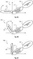
- Figs. 3a and 3b show the simulation results of steered 3D beam patterns by code-word 1 (Table 1) and code-word 2 (Table 3) separately.
- Fig. 4a shows the steered 3D beam pattern by the new code-word (Table 3), which may be the superposed beam from sub-beam 1 and sub-beam 2 using the disclosed method.
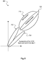
- Fig. 4b shows the power-angle spectrum of the same superposed beam.
- Fig. 3a shows code-word 1 which has the main component referred to as 301.
- Fig. 3b shows code-word 2 which has the two components referred to as 302a, 302b.
- Fig. 4a shows the superposed code-word which has superposed components 301, 302a, 302b.
- the superposition beam in Fig. 4a aggregates both beam directions of sub-beam 1 ( Fig. 3a ) and sub-beam 2 ( Fig. 3b ) precisely pursuant to the predetermined target value/threshold.
- Fig. 4b it can also be observed that the major two power lobes 401, 402 of the superposed beam are exactly reflecting in the main directions of sub-beam 1 (-30°) 301 and sub-beam 2 (60°) 302a, 302b.
- Fig. 4b further shows that the side lobes after the superposition are more than 10dB lower than the main lobes, which has only almost no performance impacts.
- a first sub-method as described in the following is related to concurrent UE beam sweeping and serving cell DL data demodulation.
- a second sub-method described below is related to neighbor cell Interference TX beam nulling in UE RX side.
- sub-method 1 i.e. UE beam sweeping and serving cell DL data demodulation performed independently, concurrently and simultaneously with one another.
- PDSCH carries the DL data traffic.
- BM CSI-RS is used for serving cell beam tracking.
- SSB is used for serving cell initial acquisition (RRC_IDLE) and then neighboring cell measurement (RRC_CONNECTED).
- QCL quasi co-location
- these three channels can be from different TX beams from different gNB TRPs but scheduled to be at the same time by the network (e.g.
- UEs it is beneficial for UEs to be able to do concurrently processing of serving cell PDSCH demodulation (KPI for DL throughput) and in parallel to apply RX beam sweeping (either CSI-RS based beam sweeping for serving cell beam tracking purpose or SSB based beam sweeping to neighboring cells measurement for handover purpose).
- KPI serving cell PDSCH demodulation
- RX beam sweeping either CSI-RS based beam sweeping for serving cell beam tracking purpose or SSB based beam sweeping to neighboring cells measurement for handover purpose.
- This sub-method is shown in Figs. 5a, 5b and 5c . Note that only 2D space model is shown but it can be easily extended to 3D space model. Note that UE beam sweeping in this figure can be CSI-RS based serving cell beam tracking, or SSB based RRM intra-frequency neighboring cell measurement. And the sweeping beam can be changed in a time-multiplexed manner.
- UE RX receives multiple sub-beams 501, 502, 503, 510 containing different signals through a single ADC in a single antenna array.
- UE RX receives multiple sub-beams 501, 502, 503, 510 containing different signals through a single ADC in a single antenna array.
- Use-case A The NR DL signals from different sub-beams are TDMed or FDMed.
- the sweeping beam 501, 502, 503 in Figs. 5a, 5b, 5c is for CSI-RS based serving cell beam tracking, while the constant beam 510 in Figs. 5a, 5b, 5c is for PDSCH serving cell demodulation.
- Use-case B The NR DL signals from different sub-beams are NOT TDMed or FDMed.
- the sweeping beam 501, 502, 503 in Figs. 5a, 5b, 5c is for SSB based neighboring cell measurement and the constant beam 510 in Figs. 5a, 5b, 5c is for PDSCH serving cell demodulation.
- inter-beam interferences exist.
- baseband can explore interference cancellation algorithms similarly as in LTE cell-edge scenarios to cancel the interferences.
- an implementation is disclosed to dynamically split the gains among superposed sub-beams, so that interference can be run-time controlled. The split can be based on the run-time channel quality measurement of each sub-beam. Note that gain splitting is supported by the disclosed algorithm (see formula (8.1) and formula (8.2)).
- the procedure of dynamical gain split for intra-array inter-beam interference control in use-case B is shown in Fig. 6 .
- Fig. 6 is an example of dynamical gain split for intra-array inter-beam interference control according to the disclosure.
- TH2 is a SINR threshold as the minimal the channel quality for neighboring cell measurement (e.g. a typical value is -6dB).
- TH1 is the SINR threshold as the minimal channel quality for serving cell PDSCH demodulation (e.g. a typical value is the DMRS SINR mapped to 10% PDSCH BLER).
- the scaling policy in Fig. 6 prioritizes the gain scaling of beam 1 over beam 2.
- the priority setting can also be more flexible by adjusting TH1 and TH2 based on inputs of higher layer information or other modem parameters: For example, when UE is in high mobility scenario while at the same time the neighboring cell data base is still empty, neighboring cell measurement has to be prioritized over DL PDSCH demodulation in order to prepare for handover and avoid call drop. In this case, TH1 can be reduced while TH2 can be increased. As a result, based on the framework in Fig. 6 higher gains will be allocated to beam 2 than beam 1.
- sub-method 1 can be extended to dynamically generate two UE RX sub-beams at the same time in different directions from single antenna array, where one sub-beam is for NR PDSCH reception and another sub-beam is for NR PDCCH reception.
- the dynamic generation of the two UE RX sub-beams may have the meaning that both (or more) UE RX sub-beams may independently be directed in different directions and may independently change their direction and may apply independent gradients of direction. This is crucial in case PDSCH beam and PDCCH beam are scheduled by gNB to be FDMed but in the same OFDM symbols: note that in current 3GPP NR slot structure, it is a still valid corner case. This avoids performance drop on UE side in such corner case when the UE has only one activated antenna array at a time.
- sub-method 2 i.e. neighbor cell Interference TX beam nulling in UE RX side.
- a narrow neighbor gNR TX interference beam from a neighboring cell
- the interference beam can be the serving gNb TX beam for another UE which is co-located.
- it makes sense to null the interference beam in UE RX side.
- a sub-method (sub-method 2) is disclosed to dynamically null the interference beam.
- sweeping sub-beam 701 is directed to top direction, while serving beam 710 and interference beam 720 point to another direction.
- neither serving beam 710 nor interference beam 720 is detected; RSRP is low and SINR is low.
- sweeping sub-beam 702 is directed closer to serving beam 710 and interference beam 720.
- a good serving beam 710 portion is detected; RSRP is high and SINR is high.
- sweeping sub-beam 703 is directed in the same direction as serving beam 710 and interference beam 720.
- a bad serving beam 710 portion is detected; RSRP is high and SINR is low.
- sweeping sub-beam 704 is directed close but not in same direction as serving beam 710 and interference beam 720.
- a good serving beam 710 portion is detected; RSRP is high and SINR is high.
- the two sweeping beams 702, 704 from times t2 and t4 according to Figs. 7b and 7d are superposed.
- each superposed sub-beam receives highly correlated signal (same baseband signal from the same gNB TRP).
- the received analog signals from different sub-beams may still have different propagation paths. This may lead to a phase delta among those correlated signals before combining them and feeding them into a single ADC. Such phase delta may lead to self-cancellation of signals after analogy combining due to strong correlation (e.g. when the phase delta is pi, then imagery part are totally cancelled).
- phase delta is zero because gNB TX are co-located, same for UE RX, to make the disclosed sub-method 2 be 100% robust against such issue
- the common phase of received signal may be compensated from each superposed sub-beam separately, so that the received coherent signals from different sub-beams have a common phase reference before being combined in front of a single ADC. This may be done in two steps:
- UE baseband measures the absolute phase of received signals (e.g. based on reference signals) from each swept sub-beam 701, 702, 703, 704.
- ⁇ ⁇ p in formula (9) is the common phase estimated during RX beam sweeping steps before applying superposition: each swept sub-beam p is associated with a separate common phase estimation (the estimation can be based on reference signals).
- the updated code-word in formula (9) is further mapped into the new code-word using formula (7.1) and formula (7.2) (or formula 8.1 and formula 8.2 if gain splitting is also considered).
- the new beam associated to the newly mapped code-word is equivalent with the superposition of those updated sub-beams which ensures all received signals from those sub-beams have the common phase basis.
- the UE can support concurrent reception of multiple DL channels which are FDMed but not QCLed (e.g. a paging PDSCH and a SSB which are FDMed within same OFDM symbols). This can be done by concurrently steering multiple UE beams from the same antenna array while each UE beam is associated to a different DL channel.
- UE can further adaptively split the gains among those channels based KPI parameters estimated from each connectivity: e.g. DL BLER, DL SINR, DL RSRP, or a joint considerations.
- the UE can support concurrent multi-connectivity operation while each connectivity is operating in a different carrier frequency within mmWave bands, and each connectivity is communicating with a base station transmission receiver point (TRP) in a different location:
- TRP base station transmission receiver point
- UE can concurrently steer multiple UE beams from the same antenna array while each UE beam is associated to one connectivity.
- UE can adaptively split the gains among those concurrent UE beams based on the KPI parameters estimated from each connectivity: e.g. DL BLER, DL CQI, DL RSRP, UL BLER or channel types (PDCCH > PDSCH), or a joint considerations.
- the UE can support FDD operation in mmWave bands while DL and UL are communicating with gNB but using different UE beams for UL and DL.
- UE can concurrently steer two UE beams from the same antenna array while one UE beam is associated to DL reception and another different UE beam is associated to UL transmission.
- UE can adaptively split the gains among those concurrent UE beams based on the KPI parameters estimated from each connectivity: e.g. DL BLER vs. UL BLER, or channel types (PDCCH>PUCCH> PUSCH with UCI > PSCCH > PUSCH without UCI), or a joint considerations.
- Fig. 9 is a block diagram illustrating an antenna array 900 for UE TX analog beamforming according to the disclosure.
- the antenna array 900 can be used for analog beamforming in both RX and TX direction.
- the antenna array 900 comprises a plurality of antenna elements 911, 921, 931.
- Each antenna element 911, 921, 931 is configured to transmit a respective analog signal 910, 920, 930 (y(1,t), y(2,t), y(N,t)).
- the antenna elements 911, 921, 931 are adjustable based on a code-word 212, 222, 232 which comprises respective phase configurations ⁇ p (1), ⁇ p (2), ⁇ p (N) of the plurality of antenna elements 911, 921, 931, e.g. as described above with respect to Fig. 2 .
- the code-word may be the same code-word or a different code-word as described above with respect to Fig. 2 .
- the code-word is based on a superposition of a predetermined set of basic code-words, e.g. basic code-words 1001, 1002, 1003 as described below with respect to Fig. 10 .
- Each basic code-word associates with a corresponding sub-beam.
- a main radiation lobe of the corresponding sub-beam points in a predefined spatial direction.
- the antenna elements 911, 921, 931 may be configured to transmit analog signals in a millimeter wave band.
- the code-word may comprise respective gain configurations g p (1), g p (2), g p (N) of the plurality of antenna elements 911, 921, 931.
- the antenna array 900 further comprises a plurality of weighting elements 913, 923, 933 to apply the code-word 212, 222, 232 to the plurality of antenna elements 911, 921, 931.
- the antenna array 900 further comprises an analog splitter 940 configured to split a composite beam signal s(t) 941 into subcomponents before being transmitted by the antenna elements 911, 921, 931.
- a digital-to-analog converter (DAC) 950 may be used to generate the composite beam signal s(t) 941.
- DAC digital-to-analog converter
- the subcomponents of the composite beam signal 941 may include two or more independent sub-beams at the same time instance.
- a first superposed sub-beam may comprise serving cell Physical Downlink Shared Channel, PDSCH, signals from a base station and a second superposed sub-beam may comprise serving cell Channel State Information Reference Signal, CSI-RS, synchronization signal block, SSB or Physical Downlink Control Channel, PDCCH, signals from the same base station.
- CSI-RS serving cell Physical Downlink Shared Channel
- SSB serving cell Channel State Information Reference Signal
- PDCCH Physical Downlink Control Channel
- each sub-beam receives physical downlink control channel, PDCCH, or physical downlink shared channel, PDSCH signals from different connectivities in different carrier frequencies but both within 5G NR frequency range 2, FR2.
- the different connectivities may be provided by different base stations.
- Each connectivity may be associated to a respective SIM card.
- each sub-beam transmits physical uplink control channel, PUCCH, or physical uplink shared channel, PUSCH signals to different connectivities in different carrier frequencies but both within 5G NR frequency range 2, FR2.
- the different connectivities may be provided by different base stations in mmWave bands.
- Each connectivity may be associated to a respective SIM card.
- the code-word is adapted based on splitting a gain of the code-word between the gain configurations of the at least two sub-beams.
- the gain split may be based on uplink block error, UL BLER, measurement for each connectivity.
- the UL BLER may be determined based on counting a number of PUSCH NACKs indicated by the respective base station.
- the disclosed methods described above may also be applied with the antenna array 900 for UE TX analog beamforming as shown in Fig. 9 .
- Fig. 10 is a block diagram illustrating a UE circuit 1000 comprising an antenna array 1010 for analog beamforming according to the disclosure.
- the UE circuit 1000 comprises an antenna array 1010 which is adjustable based on a code-word 1004; and a controller 1020 configured to provide the code-word 1004 based on a superposition of a predetermined set of basic code-words 1001, 1002, 1003.
- Each basic code-word 1001, 1002, 1003 associates with a corresponding sub-beam and a main radiation lobe of the corresponding sub-beam points in a predefined spatial direction.
- the antenna array 1010 may correspond to an antenna array 200 as described above with respect to Fig. 2 or to an antenna array 900 as described above with respect to Fig. 9 .
- the antenna array 1010 can be used for analog beamforming in both RX and TX direction.
- the antenna array 1010 comprises a plurality of antenna elements, e.g. antenna elements 211, 221, 231 as described above with respect to Fig. 2 .
- the antenna elements can work independently of one another, and concurrently and simultaneously.
- Each antenna element 211, 221, 231 is configured to receive a respective analog signal r(1,t), r(2,t), r(N,t).
- the antenna elements 211, 221, 231 are adjustable based on a code-word 1004, e.g. a code-word 212, 222, 232 as described above with respect to Fig.
- the code-word 1004 is based on a superposition of a predetermined set of basic code-words 1001, 1002, 1003. Each basic code-word 1001, 1002, 1003 associates with a corresponding sub-beam. A main radiation lobe of the corresponding sub-beam points in a predefined spatial direction.
- the antenna elements 211, 221, 231 may be configured to receive analog signals in a millimeter wave band.
- the code-word 1004 may comprise respective gain configurations g p (1), g p (2), g p (N) of the plurality of antenna elements 211, 221, 231.
- the antenna array 200 further comprises a plurality of weighting elements, e.g. weighting elements 213, 223, 233 as described above with respect to Fig. 2 to apply the code-word 1004 to the plurality of antenna elements 211, 221, 231.
- the antenna array 1010 may form a composite beam s(t) 241 comprising two or more independent sub-beams at the same time instance.
- a first superposed sub-beam may comprise serving cell Physical Downlink Shared Channel, PDSCH, signals from a base station; and a second superposed sub-beam may comprise serving cell Channel State Information Reference Signal, CSI-RS, or Physical Downlink Control Channel, PDCCH, signals or serving cell SSB from the same base station.
- the serving cell PDSCH signals and the serving cell CSI-RS or PDCCH signals or SSB may be non-quasi co-located with the serving cell PDSCH signals.
- the serving cell PDSCH signals and the CSI-RS or PDCCH signals or the SSB may be included in the same OFDM symbol.
- a first superposed sub-beam may comprise serving cell PDSCH signals from a base station; and a second superposed sub-beam may comprise neighboring cell synchronization signal block, SSB, signals from another base station.
- SSB neighboring cell synchronization signal block
- a first superposed sub-beam may cover a first sub-set of radiation patterns comprising PDSCH, signals; and a second superposed sub-beam may cover a second sub-set of radiation patterns comprising the same PDSCH signals.
- Each basic code-word 1001, 1002, 1003 may comprise respective phase configurations ⁇ p (1), ⁇ p (2), ⁇ p (N) of the antenna array 1010 as shown in Fig. 10 .
- Each basic code-word may comprise respective gain configurations g p (1), g p (2), g p (N)) of the antenna array 1010 as shown in Fig. 10 .
- At least two sub-beams may comprise different downlink signals.
- the controller 1020 may be configured to adapt the code-word based on splitting a gain of the code-word between the gain configurations of the at least two sub-beams.
- the gain splitting may be based on channel qualities of the at least two sub-beams.
- the channel qualities may be based on reference signals of the at least two sub-beams.
- the channel qualities can be based on UL BLER measurement, e.g. UE counting the number of PUSCH NACKs which are indicated by base station.
- the gain splitting may be based on UE internal information about a neighboring cell database.
- the gain splitting may be based on mobility information based on UE internal estimates or based on external sensors.
- the controller 1020 may be configured to select the sub-beams based on a beam sweeping over a set of candidate sub-beams.
- the controller 1020 may be configured to determine for each swept candidate sub-beam: a received signal power, a received interference-plus-noise, and a received absolute common phase.
- the controller 1020 may be configured to perform the beam sweeping based on PDSCH DMRS subcarrier signals or based on PDSCH data subcarrier signals or based on the CSI-RS resources which are co-quasi-collocated with PDSCH.
- the controller 1020 may be configured to select a candidate sub-beam for superposition if a receive power (or a received SINR or both) or a received quality of the candidate sub-beam is above a predefined threshold.
- a basic code-word 1001, 1002, 1003 of each selected candidate sub-beam may be offset by a common phase value.
- the antenna array may form a composite beam s(t) 241 comprising two or more independent sub-beams at the same time instance, e.g. as described above with respect to Fig. 2 .
- a first superposed sub-beam may comprise serving cell Physical Downlink Shared Channel, PDSCH, signals from a base station and a second superposed sub-beam may comprise serving cell Channel State Information Reference Signal, CSI-RS, synchronization signal block, SSB or Physical Downlink Control Channel, PDCCH, signals from the same base station.
- CSI-RS serving cell Physical Downlink Shared Channel
- SSB serving cell Channel State Information Reference Signal
- PDCCH Physical Downlink Control Channel
- each sub-beam receives physical downlink control channel, PDCCH, or physical downlink shared channel, PDSCH signals from different connectivities in different carrier frequencies but both within 5G NR frequency range 2, FR2.
- the different connectivities may be provided by different base stations.
- Each connectivity may be associated to a respective SIM card.
- each sub-beam transmits physical uplink control channel, PUCCH, or physical uplink shared channel, PUSCH signals to different connectivities in different carrier frequencies but both within 5G NR frequency range 2, FR2.
- the different connectivities may be provided by different base stations in mmWave bands.
- Each connectivity may be associated to a respective SIM card.
- 3GPP provides in specification for 5G NR and TS 38.104 section 5.2 the list of bands in which NR (New Radio) can operate. As per 3GPP release 15, these frequency bands are designated for different frequency ranges (FR) and current specification (Release) defines them as FR1 and FR2.
- FR1 is defined ranging from 450 MHz to 6000 MHz
- FR2 is defined ranging from 24250 MHz to 52600 MHz.
- the code-word is adapted based on splitting a gain of the code-word between the gain configurations of the at least two sub-beams.
- the gain split may be based on uplink block error, UL BLER, measurement for each connectivity.
- the UL BLER may be determined based on counting a number of PUSCH NACKs indicated by the respective base station.
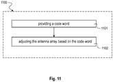
- Fig. 11 is a schematic diagram illustrating a method 1100 for adjusting an antenna array according to the disclosure.
- the method 1100 may be applied with an antenna array 200 described above with respect to Fig. 2 or an antenna array 900 described above with respect to Fig. 9 or an antenna array 1010 described above with respect to Fig. 10 .
- the method 1100 comprises: providing 1101 a code-word based on a superposition of a predetermined set of basic code-words, wherein each basic code-word associates with a corresponding sub-beam, wherein a main radiation lobe of the corresponding sub-beam points in a predefined spatial direction, e.g. as described above with respect to Fig. 10 ; and adjusting 1102 the antenna array based on the code-word.
- Each basic code-word may comprise respective phase configurations ⁇ p (1), ⁇ p (2), ⁇ p (N) of the antenna array.
- Each basic code-word may comprise respective gain configurations g p (1), g p (2), g p (N) of the antenna array.
- At least two sub-beams may be configured to comprise different downlink signals.
- the code-word may be adapted based on splitting a gain of the code-word between the gain configurations of the at least two sub-beams.
- the gain splitting may be based on channel qualities of the at least two sub-beams.
- the channel qualities may be based on reference signals of the at least two sub-beams.
- the channel qualities may be based on uplink block error, UL BLER, measurements, e.g. by UE counting the number of PUSCH NACKs which are indicated by the base station.
- the gain splitting may be based on UE internal information about a neighboring cell database.
- the gain splitting may be based on mobility information based on UE internal estimates or based on external sensors.
- the method 1100 may further comprise: selecting the sub-beams based on a beam sweeping over a set of candidate sub-beams.
- the method 1100 may further comprise: determining for each swept candidate sub-beam: a received signal power, a received interference-plus-noise, and a received absolute common phase.
- the method 1100 may further comprise: performing the beam sweeping based on PDSCH DMRS subcarrier signals or based on PDSCH data subcarrier signals or based on CSI-RS signals which are indicated to be QCLed with PDSCH.
- the method 1100 may further comprise: selecting a candidate sub-beam for superposition if a receive power of the candidate sub-beam is above a predefined threshold.
- a basic code-word of each selected candidate sub-beam may be offset by a common phase value.
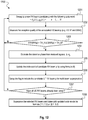
- Fig. 12 is a schematic diagram illustrating a procedure for interference beam nulling 1200 according to the disclosure.
- the procedure 1200 describes the beam nulling as exemplarily illustrated in Figs. 7a, 7b, 7c, 7d and 8 in terms of a method.
- measuring the reception quality of the associated RX beam p is performed, e.g. RSRP and SINR.
- a check is performed if RSRP(p)>TH_A and SINR(p)>TH_B.
- TH_A and TH_B are a lower and a higher threshold. If no, the procedure returns to block 1201, if yes, a fourth block 1204 is performed estimating the common phase from received signals, ⁇ p . Then, in a fifth block 1205 updating the code-word of candidate RX beam p is performed by using formula (9) described above. In a succeeding sixth block 1206 a flag is setup to include the candidate UE RX beam p for multi-beam superposition. Afterwards, in a seventh block 1207, a check is performed if all UE RX beams have already been swept. If no, the procedure 1200 returns to block 1201, if yes, in an eighth block 1208 the selected RX beam candidates are superposed with updated code-words by formula (7.1, 7.2) or (8.1, 8.2) as described above.
- DSP Digital Signal Processors
- ASIC application specific integrated circuit
- Embodiments described in this disclosure can be implemented in digital electronic circuitry, or in computer hardware, firmware, software, or in combinations thereof, e.g. in available hardware of mobile devices or in new hardware dedicated for processing the methods described herein.
- the present disclosure also supports a computer program product including computer executable code or computer executable instructions that, when executed, causes at least one computer to execute the performing and computing blocks described herein, in particular the methods described above with respect to Figs. 5 to 8 and 11 and the computing blocks described above with respect to Figs. 2 , 9 and 10 .
- a computer program product may include a non-transient readable storage medium storing program code thereon for use by a processor, the program code comprising instructions for performing the methods or the computing blocks as described above.
- Example 1 is an antenna array circuitry for analog beamforming, the antenna array circuitry comprising: a plurality of antenna elements, wherein each antenna element is configured to receive a respective analog signal (r(1,t), r(2,t), r(N,t)), wherein the plurality of antenna elements is adjustable based on a code-word, wherein the code-word comprises respective phase configurations ( ⁇ p (1), ⁇ p (2), ⁇ p (N)) of the plurality of antenna elements, wherein the code-word is based on a superposition of a predetermined set of basic code-words, wherein each basic code-word associates with a corresponding sub-beam, wherein a main radiation lobe of the corresponding sub-beam points in a predefined spatial direction.
- Example 2 the subject matter of Example 1 can optionally include that the plurality of antenna elements is configured to receive analog signals in a millimeter wave band.
- Example 3 the subject matter of any one of Examples 1-2 can optionally include that the code-word comprises respective gain configurations (g p (1), g p (2), g p (N))) of the plurality of antenna elements.
- Example 4 the subject matter of any one of Examples 1-2 can optionally include: a plurality of weighting elements configured to apply the code-word to the plurality of antenna elements; and an analog adder configured to add outputs of the plurality of antenna elements to form a composite beam (s(t)).
- Example 5 the subject matter of any one of Examples 1-2 can optionally include that the antenna array circuitry is configured to form a composite beam comprising at least two independent sub-beams at the same time instance.
- Example 6 the subject matter of Example 5 can optionally include that a first superposed sub-beam is configured to comprise serving cell Physical Downlink Shared Channel, PDSCH, signals from a base station; and that a second superposed sub-beam is configured to comprise serving cell Channel State Information Reference Signal, CSI-RS, synchronization signal block, SSB or Physical Downlink Control Channel, PDCCH, signals from the same base station.
- a first superposed sub-beam is configured to comprise serving cell Physical Downlink Shared Channel, PDSCH, signals from a base station; and that a second superposed sub-beam is configured to comprise serving cell Channel State Information Reference Signal, CSI-RS, synchronization signal block, SSB or Physical Downlink Control Channel, PDCCH, signals from the same base station.
- CSI-RS serving cell Channel State Information Reference Signal
- SSB synchronization signal block
- PDCCH Physical Downlink Control Channel
- Example 7 the subject matter of Example 5 can optionally include that each sub-beam receives physical downlink control channel, PDCCH, or physical downlink shared channel, PDSCH signals from different connectivities in different carrier frequencies but both within 5G NR frequency range 2, FR2, that the different connectivities are provided by different base stations, and that multiple connectivities are associated to different base stations or to different transmit-receive points, TRPs, of a same base station.
- PDCCH physical downlink control channel
- PDSCH signals from different connectivities in different carrier frequencies but both within 5G NR frequency range 2, FR2
- the different connectivities are provided by different base stations
- multiple connectivities are associated to different base stations or to different transmit-receive points, TRPs, of a same base station.
- each sub-beam receives physical downlink control channel, PDCCH, or physical downlink shared channel, PDSCH signals from different connectivities in different carrier frequencies but both within 5G NR frequency range 2, FR2, and that the different connectivities are provided by different base stations, wherein multiple connectivities are associated to different base stations or to different transmit-receive points, TRPs, of a same base station.
- PDCCH physical downlink control channel
- PDSCH signals from different connectivities in different carrier frequencies but both within 5G NR frequency range 2, FR2
- FR2 physical downlink control channel
- PDSCH signals from different connectivities in different carrier frequencies but both within 5G NR frequency range 2, FR2
- the different connectivities are provided by different base stations, wherein multiple connectivities are associated to different base stations or to different transmit-receive points, TRPs, of a same base station.
- TDD operation time multiplexed
- Example 8 the subject matter of Example 5 can optionally include that each sub-beam transmits physical uplink control channel, PUCCH, or physical uplink shared channel, PUSCH signals to different connectivities in different carrier frequencies but both within 5G NR frequency range 2, FR2, and that the different connectivities are provided by different base stations in mmWave bands, each connectivity associated to a respective SIM card.
- PUCCH physical uplink control channel
- PUSCH physical uplink shared channel
- Example 9 the subject matter of any one of Examples 7-8 can optionally include that the code-word is adapted based on splitting a gain of the code-word between the gain configurations of the at least two sub-beams, that the gain split for user equipment transmission, UE TX, is based on uplink block error rate, UL BLER, measurement for each connectivity, that the UL BLER is determined based on counting a number of PUSCH NACKs indicated by the respective base station within a predetermined time window, and that the gain split for user equipment reception, UE RX, is based on downlink block error rate, DL BLER, measurement or downlink channel quality measurement for each connectivity.
- Example 10 the subject matter of Example 6 can optionally include that the serving cell CSI-RS, SSB or PDCCH signals are non-quasi co-located with the serving cell PDSCH signals.
- Example 11 the subject matter of Example 6 can optionally include that the serving cell PDSCH signals and the CSI-RS, SSB or PDCCH signals are comprised in a same OFDM symbol.
- Example 12 the subject matter of Example 5 can optionally include that a first superposed sub-beam is configured to comprise serving cell PDSCH signals from a base station; and that a second superposed sub-beam is configured to comprise neighboring cell synchronization signal block, SSB, signals from another base station.
- a first superposed sub-beam is configured to comprise serving cell PDSCH signals from a base station
- a second superposed sub-beam is configured to comprise neighboring cell synchronization signal block, SSB, signals from another base station.
- Example 13 the subject matter of Example 5 can optionally include that a first superposed sub-beam is configured to cover a first sub-set of radiation patterns comprising PDSCH, signals; and that a second superposed sub-beam is configured to cover a second sub-set of radiation patterns comprising the same PDSCH signals.
- Example 14 is a user equipment, UE, circuit, comprising: an antenna array circuitry, wherein the antenna array circuitry is adjustable based on a code-word; and a controller configured to provide the code-word based on a superposition of a predetermined set of basic code-words, wherein each basic code-word associates with a corresponding sub-beam, wherein a main radiation lobe of the corresponding sub-beam points in a predefined spatial direction.
- Example 15 the subject matter of Example 14 can optionally include that each basic code-word comprises respective phase configurations ( ⁇ p (1), ⁇ p (2), ⁇ p (N)) of the antenna array circuitry.
- each basic code-word comprises respective gain configurations (g p (1), g p (2), g p (N))) of the antenna array circuitry.
- Example 17 the subject matter of Example 16 can optionally include that at least two sub-beams are configured to comprise different downlink signals.
- Example 18 the subject matter of Example 17 can optionally include that the controller is configured to adapt the code-word based on splitting a gain of the code-word between the gain configurations of the at least two sub-beams.
- Example 19 the subject matter of Example 18 can optionally include that the gain splitting is based on channel qualities of the at least two sub-beams.
- Example 20 the subject matter of Example 19 can optionally include that the channel qualities are based on reference signals of the at least two sub-beams.
- Example 21 the subject matter of Example 20 can optionally include that the channel qualities are based on uplink block error, UL BLER, measurements.
- Example 22 the subject matter of Example 18 can optionally include that the gain splitting is based on UE internal information about a neighboring cell database.
- Example 23 the subject matter of Example 18 can optionally include that the gain splitting is based on mobility information based on UE internal estimates or based on external sensors.
- Example 24 the subject matter of any one of Examples 14-15 can optionally include that the controller is configured to select the sub-beams based on a beam sweeping over a set of candidate sub-beams.
- Example 25 the subject matter of Example 24 can optionally include that the controller is configured to determine for each swept candidate sub-beam: a received signal power, a received interference-plus-noise, and a received absolute common phase.
- Example 26 the subject matter of Example 25 can optionally include that the controller is configured to perform the beam sweeping based on PDSCH DMRS subcarrier signals or based on PDSCH data subcarrier signals or based on channel state information reference signal, CSI-RS, resources which are quasi collocated with PDSCH signals.
- the controller is configured to perform the beam sweeping based on PDSCH DMRS subcarrier signals or based on PDSCH data subcarrier signals or based on channel state information reference signal, CSI-RS, resources which are quasi collocated with PDSCH signals.
- Example 27 the subject matter of Example 24 can optionally include that the controller is configured to select a candidate sub-beam for superposition if a receive quality of the candidate sub-beam is above a predefined threshold.
- Example 28 the subject matter of Example 24 can optionally include that a basic code-word of each selected candidate sub-beam is offset by a common phase value.
- Example 29 is a method for adjusting an antenna array circuitry, the method comprising: providing a code-word based on a superposition of a predetermined set of basic code-words, wherein each basic code-word associates with a corresponding sub-beam, wherein a main radiation lobe of the corresponding sub-beam points in a predefined spatial direction; and adjusting the antenna array circuitry based on the code-word.
- Example 30 the subject matter of Example 29 can optionally include that each basic code-word comprises respective phase configurations ( ⁇ p (1), ⁇ p (2), ⁇ p (N)) of the antenna array circuitry.
- each basic code-word comprises respective gain configurations (g p (1), g p (2), g p (N))) of the antenna array circuitry.
- Example 32 the subject matter of Example 31 can optionally include that at least two sub-beams are configured to comprise different downlink signals.
- Example 33 the subject matter of Example 32 can optionally include: adapting the code-word based on splitting a gain of the code-word between the gain configurations of the at least two sub-beams.
- Example 34 the subject matter of Example 33 can optionally include that the gain splitting is based on channel qualities of the at least two sub-beams.
- Example 35 the subject matter of Example 34 can optionally include that the channel qualities are based on reference signals of the at least two sub-beams.
- Example 36 the subject matter of Example 33 can optionally include that the gain splitting is based on UE internal information about a neighboring cell database.
- Example 37 the subject matter of Example 33 can optionally include that the gain splitting is based on mobility information based on UE internal estimates or based on external sensors.
- Example 38 the subject matter of any one of Examples 29-30 can optionally include: selecting at least two sub-beams based on a beam sweeping over a set of candidate sub-beams.
- Example 39 the subject matter of Example 38 can optionally include: determining for each swept candidate sub-beam: a received signal power, a received interference-plus-noise, and a received absolute common phase.
- Example 40 the subject matter of Example 39 can optionally include: performing the beam sweeping based on PDSCH DMRS subcarrier signals or based on PDSCH data subcarrier signals or based on channel state information reference signals, CSI-RS, which are indicated to be quasi-collocated with PDSCH signals.
- Example 41 the subject matter of Example 38 can optionally include: selecting a candidate sub-beam for superposition if a receive power of the candidate sub-beam is above a predefined threshold.
- Example 42 the subject matter of Example 38 can optionally include that a basic code-word of each selected candidate sub-beam is offset by a common phase value.
- Example 43 is a device for adjusting an antenna array circuitry, the device comprising: means for providing a code-word based on a superposition of a predetermined set of basic code-words, wherein each basic code-word associates with a corresponding sub-beam, wherein a main radiation lobe of the corresponding sub-beam points in a predefined spatial direction; and means for adjusting the antenna array circuitry based on the code-word.
- Example 44 the subject matter of Example 43 can optionally include that each basic code-word comprises respective phase configurations ( ⁇ p (1), ⁇ p (2), ⁇ p (N)) of the antenna array circuitry.
- Example 45 the subject matter of any one of Examples 43-44 can optionally include that each basic code-word comprises respective gain configurations (g p (1), g p (2), g p (N))) of the antenna array circuitry.
- Example 46 is a computer readable non-transitory medium on which computer instructions are stored which when executed by a computer cause the computer to perform the method of any one of Examples 29 to 42.
- Example 47 is a system, comprising: an antenna array circuitry comprising a plurality of antenna elements, wherein the antenna elements are adjustable based on a code-word; a controller configured to provide the code-word based on a superposition of a predetermined set of basic code-words, wherein each basic code-word associates with a corresponding sub-beam, wherein a main radiation lobe of the corresponding sub-beam points in a predefined spatial direction; a plurality of weighting elements configured to apply the code-word to the plurality of antenna elements; and an analog adder configured to add outputs of the plurality of antenna elements to form a composite beam (s(t)).
- an antenna array circuitry comprising a plurality of antenna elements, wherein the antenna elements are adjustable based on a code-word
- a controller configured to provide the code-word based on a superposition of a predetermined set of basic code-words, wherein each basic code-word associates with a corresponding sub-beam, wherein
- Example 48 the subject matter of Example 47 can optionally include that the composite beam comprises at least two independent sub-beams at the same time instance.
- Example 49 is a method of dynamical user equipment beamforming in mmWave bands within one antenna, where the formed beam is the superposition of multiple sub-beams whose main radiation lobes are in different spatial directions.
- Example 50 the subject matter of Example 49 can optionally include that the beam forming is achieved by dynamically selecting a set of code-words each associated to a pre-optimized sub-beam and map them into a new code-word, wherein a code-word consists of a set of phase shifter settings and a set of gain settings while each pair of phase shifter and gain setting is applied per antenna element within one antenna array circuitry.
- Example 51 the subject matter of any one of Examples 49-50 can optionally include that at the same time instance, one superposed sub-beam carries serving cell PDSCH signals from a base station, while another superposed sub-beam carries serving cell beam management CSI-RS signals in the same OFDM symbol from the same base station but not quasi co-located (QCLed) with its PDSCH.
- one superposed sub-beam carries serving cell PDSCH signals from a base station
- another superposed sub-beam carries serving cell beam management CSI-RS signals in the same OFDM symbol from the same base station but not quasi co-located (QCLed) with its PDSCH.
- QLed quasi co-located
- Example 52 the subject matter of any one of Examples 49-50 can optionally include that at the same time instance, one superposed sub-beam carries serving cell PDSCH signals from one base station while another superposed sub-beam carries PDCCH signals from the same base station in the same OFDM symbol but not co-located (QCLed) with its PDSCH.
- Example 53 the subject matter of any one of Examples 49-50 can optionally include that at the same time instance, one superposed sub-beam carries serving cell PDSCH signals from one base station TRP (Transmit-Receive Point) while another superposed sub-beam carries neighboring cell SSB signals from a different base station TRP.
- TRP Transmit-Receive Point
- Example 54 the subject matter of any one of Examples 51-53 can optionally include that UE dynamically splits the gain portions between the superposed two sub-beams carrying different downlink signals.
- Example 55 the subject matter of Example 54 can optionally include that the gain splitting is based on the channel quality measurements from reference signals in different sub-beams.
- Example 56 the subject matter of Example 54 can optionally include that the gain splitting is based on UE modem internal information of neighboring cell database.
- Example 57 the subject matter of Example 54 can optionally include that the gain splitting is based on mobility information from UE modem internal estimates or be based on mobility information from external sensors.
- Example 58 the subject matter of any one of Examples 49-50 can optionally include that at the same time instance, one superposed sub-beam covers a sub-set of spatial coverage of base station TRP transmission radian pattern transmitting downlink PDSCH signals, while another superposed sub-beam covers a different sub-set of spatial coverage of the same base station TRP transmission radian pattern transmitting the same PDSCH downlink signals.
- Example 59 the subject matter of Example 58 can optionally include that the sub-beams which are superposed based on Example 49 or Example 50 are selected by first sweeping a set of narrow sub-beam candidates.
- Example 60 the subject matter of Example 59 can optionally include that during candidate sub-beam sweeping, for each swept sub-beam candidate, UE measures the received useful signal power, the received interference plus noise power, and the absolute common phase of the received useful signal.
- Example 61 the subject matter of Example 60 can optionally include that the measurement is based on PDSCH DMRS sub-carrier signals.
- Example 62 the subject matter of Example 60 can optionally include that the measurement is based on PDSCH data sub-carrier signals.
- Example 63 the subject matter of Example 59 can optionally include that a candidate sub-beam is selected to be superposed only if the measured received power are higher than a pre-defined threshold, meanwhile the measured signal noise interference ratio (SINR) is higher than another predefined threshold.
- SINR measured signal noise interference ratio
- Example 64 the subject matter of Example 58 can optionally include that the code-word of each selected superposed sub-beam, which is used to determine the superposition code-word, is offset by a common phase value estimated during the RX beam sweeping steps in Example 60, when the selected sub-beam is applied.
Abstract
Description
- The disclosure relates to techniques for analog beamforming applicable in 5G NR mmWave communications, in particular an antenna array circuitry and a user equipment (UE) circuit comprising such antenna array circuitry. The disclosure further relates to devices and methods of dynamical multi-beam superposition with adaptive gain split within single antenna array and their applications for UE performance optimizations in 5G NR mmWave communications.
- Analog beam forming is one major feature introduced by 5G
NR mmWave communications 100 as exemplarily shown inFig. 1 where UE 110 communicates with serving gNB 120 by forming one ormore antenna beams gNB 130. Analog beamforming is achieved by antenna arrays (also named as antenna panels). Currently it is assumed that there is one formed analog beam at the same time per antenna array (antenna panel), or 2 formed analog beams (one Vertical, V beam and one Horizontal, H beam) when considering dual-polarizations. However, H/V beams have dependency with each other, e.g. V/H beams need to provide UE the antenna diversity for MIMO operations, so they cannot be in totally different directions. Therefore, when UE needs concurrent operation of multiple independent beams in different directions, it needs more than 1 antenna array to be operating at the same time. This requirement results in multiple antenna array hardware, i.e. increased hardware cost, increased power consumption. Besides, multiple antenna arrays may not fit into the limited space of a cell phone. - The accompanying drawings are included to provide a further understanding of embodiments and are incorporated in and constitute a part of this specification. The drawings illustrate embodiments and together with the description serve to explain principles of embodiments. Other embodiments and many of the intended advantages of embodiments will be readily appreciated as they become better understood by reference to the following detailed description.
-
Fig. 1 is an exemplary schematic diagram illustrating a 5G NRmmWave communications system 100 where UEs (User Equipments) 110 communicate with gNBs (or base stations) 120, 130 by applying analog beam forming. -
Fig. 2 is an exemplary block diagram illustrating anantenna array 200 for UE RX analog beamforming according to the disclosure. -
Fig. 3a is an exemplary3D radiation pattern 300a diagram of an exemplaryfirst sub-beam 301. -
Fig. 3b is an exemplary3D radiation pattern 300b diagram of an exemplarysecond sub-beam -
Fig. 4a is an exemplary3D radiation pattern 400a of a superposed beam resulting from superposition of first 301 and second 302a, 302b sub-beams as shown inFig. 3 . -
Fig. 4b is an exemplarypower angle spectrum 400b of the superposed beam shown inFig. 4a . -
Figs. 5a, 5b, 5c areexemplary radiation patterns -
Fig. 6 is an example of dynamical gain split for intra-array inter-beam interference control according to the disclosure. -
Figs. 7a, 7b, 7c, 7d illustrate exemplary different blocks of a method of narrow interference beam nulling by concurrent intra-array multi-beam superposition according to the disclosure. -
Fig. 8 illustrates an exemplary resulting block of a method of narrow interference beam nulling as shown above with respect toFigs. 7a, 7b, 7c, 7d . -
Fig. 9 is an exemplary block diagram illustrating an antenna array for UE TX analog beamforming according to the disclosure. -
Fig. 10 is an exemplary block diagram illustrating aUE circuit 1000 comprising anantenna array 1010 for analog beamforming according to the disclosure. -
Fig. 11 is an exemplary schematic diagram illustrating amethod 1100 for adjusting an antenna array according to the disclosure. -
Fig. 12 is an exemplary schematic diagram illustrating a procedure for interference beam nulling according to the disclosure. - In the following detailed description, reference is made to the accompanying drawings, which form a part thereof, and in which is shown by way of illustration specific aspects in which the invention may be practiced. It is understood that other aspects may be utilized and structural or logical changes may be made without departing from the scope of the present invention. The following detailed description, therefore, is not to be taken in a limiting sense, and the scope of the present invention is defined by the appended claims.
- The following terms, abbreviations and notations will be used herein:
- UE:
- User Equipment
- LTE:
- Long Term Evolution
- mmWave:
- millimeter-wave
- 5G NR:
- 3GPP fifth generation new radio specifications
- RX:
- Receive
- TX:
- Transmit
- PDSCH:
- Physical Downlink shared channel
- PDCCH:
- Physical Downlink control channel
- PUSCH:
- Physical Uplink shared channel
- PUCCH:
- Physical Uplink control channel
- CSI-RS:
- Channel state information reference signals
- TDM:
- time division multiplex
- FDM:
- frequency division multiplex
- SSB:
- synchronization signal block
- RAN:
- radio access network
- OFDM:
- orthogonal frequency division multiplex
- gNB:
- base station according to 5G NR terminology
- FW:
- firmware
- HW:
- hardware
- SINR:
- signal plus interference to noise ratio
- RSRP:
- received signal receive power
- QCL:
- quasi-collocation
- TRP:
- transmit-receive point
- KPI:
- Key performance indicator
- DMRS:
- Demodulation reference signal
- BLER:
- block error ratio
- ADC:
- analog-to-digital converter
- BLER:
- block error rate
- It is understood that comments made in connection with a described method may also hold true for a corresponding device configured to perform the method and vice versa. For example, if a specific method step is described, a corresponding device may include a unit to perform the described method step, even if such a unit is not explicitly described or illustrated in the figures. Further, it is understood that the features of the various exemplary aspects described herein may be combined with each other, unless specifically noted otherwise.
- The techniques described herein may be implemented in wireless communication networks, in particular communication networks based on mobile communication standards such as 5G new radio (NR), in particular for millimeter-wave data rate. The techniques may also be applied in LTE networks, in particular LTE-A and/or OFDM and successor standards. The methods are also applicable for high speed communication standards from the 802.11 family according to the WiFi alliance, e.g. 802.11ad and successor standards. The methods and devices described below may be implemented in electronic devices such as cellular handsets and mobile or wireless devices or User Equipment communicating with access points and/or base stations. The described devices may include integrated circuits and/or passives and may be manufactured according to various technologies. For example, the circuits may be designed as logic integrated circuits, ASICs, analog integrated circuits, mixed signal integrated circuits, optical circuits, memory circuits and/or integrated passives.
- The techniques described herein may be implemented in antenna arrays, e.g. antenna arrays that may be represented by the
antenna array model 200 for UE RX analog beamforming shown inFig. 2 and/or theantenna model 900 for UE RX analog beamforming shown inFig. 9 . - In the system model of
Fig. 2 ,N is the number ofantenna elements antenna array 200. r(k,t),k=1,2,...,N is the receivedanalog signal antenna element vector antenna elements antenna array 200 is called one code-word (a phase vector + optionally a gain vector). For each code-word p, the analog beam-formedsignal 241 at receiver side is then represented in the following form:
antenna element - A fundamental concept of the disclosure presented in the following is to generate multiple beams (i.e. more than one) that work independently, while collaborate concurrently and simultaneously, with one another in covering different directions or angles at the same time by a single antenna array. When UE DL needs to demodulate data traffic from the serving cell PDSCH beam, the UE can at the same time test other candidate beams (e.g. RX beam sweeping) or apply measurement of intra-frequency neighboring cells in different beam directions without interrupting the DL PDSCH demodulation. When a serving cell beam is interfered by a narrow interference beam from a neighbor cell, the interference beam can be nulled in UE receiver side without degrading beam coverage from the serving cell.
- First, a method to dynamically superpose a set of pre-optimized sub-beams within one antenna array is provided. The method dynamically selects and maps a set of pre-optimized code-words into a new code-word, where each pre-optimized code-word is associated with a pre-optimized narrow sub-beam in a different direction. The mapping is performed in such a way that the beam formed by the new code-word is equivalent with analog superposition of those sub-beams. The mapping not only considers phase per antenna element but also optionally the gains. Furthermore, consider the total gain per antenna array is limited, the proposed mapping method supports to split different gains for different sub-beams so that trade-off between different sub-beams can be made (e.g. adaptive to channel qualities per sub-beam). This approach does not need HW changes of the classic antenna array as described in the Background section. It achieves analog multi-beam superposition, but avoids additional HW costs of additional phase shifters or additional HW costs of analog combiner within the antenna array.
- Based on the basic method, key sub-methods as described in the following are introduced to optimize for 5G NR mmWave UE operations.
- A first sub-method is to dynamically superpose a sweeping UE RX sub-beam on top of a constant UE RX sub-beam in a same antenna array, so that UE can apply NR serving cell PDSCH demodulation and NR UE beam sweeping (e.g. CSI-RS based serving beam tracking or SSB based neighboring cell measurement) at the same time without interrupting serving cell DL PDSCH demodulation. Note that in this presented sub-method, compared with classic multi-antenna-array RX operations, hereby the UE RX receives multiple sub-beams of different signals through a single ADC in a single antenna array. In case the signals from different sub-beams are TDMed or FDMed (e.g. CSI-RS based serving beam tracking + PDSCH serving cell demodulation), then there is no inter-beam interference. In case the signals from different sub-beams are neither TDMed nor FDMed (e.g. SSB based neighboring cell measurement + PDSCH serving cell demodulation), inter-beam interference exists. Hereby, the gains can be dynamically split among superposed sub-beams, so that inter-beam interference can be run-time controlled. The split may be based on the run-time channel quality measurement of each sub-beam. Remind that gain splitting is supported by the presented algorithm (see formula (8.1) and formula (8.2)).
- Further note that, this sub-method can be extended to dynamically generate two UE RX sub-beams at the same time in different directions from single antenna array, where one sub-beam is for NR PDSCH reception and another sub-beam is for NR PDCCH reception. This is extremely helpful in case PDSCH beam and a different PDCCH beam are scheduled by gNB to be FDMed but in the same OFDM symbols. Note that in current 3GPP NR slot structure, this is still a valid corner case. The method avoids DL demodulation performance drop in UE side in such corner case when the UE has only one activated antenna array at a time.
- A second sub-method is to null a narrow neighboring cell beam which is partially overlapping with a serving cell beam. It is done by first detecting the narrow interference beam through UR RX beam sweeping, and then superpose multiple narrow beams within the coverage of serving cell beam but not in the coverage of the narrow interference beam.
- First, all the solutions described above may be solved on UE side without needing concurrent operation of multiple antenna arrays. This reduces the power consumption and cost of modem based UEs.
- Second, the disclosed method significantly reduces the number of per-optimized code-words before product development because only a set of per-optimized code-words reflecting a set of basic sub-beams need to be stored. Run-time superposition of those basic sub-beams can make UE adapted to different scenarios: e.g. superposition of a couple of neighboring narrow beams leads to a wider beam. This reduces the code-word memory and also significantly reduces the lab characterization time for pre-optimized code-words.
- Furthermore, by using the disclosed method, the sub-beams which are superposed are fully synchronized, so the final formed beam after superposition has little inter-beam impairments compared with concurrent multiple antenna array operations which are not perfectly synchronized. This is especially important for UE TX operation which needs strictly time synchronization among TX beams, otherwise the finally formed TX beam can be totally different than expectation.
- In the methods, devices and systems described in the following, synchronization signal blocks (SSBs) may be used. In order to connect to the network UEs need to perform initial cell search. The objective of initial cell search is to find a strong cell for potential connection, obtain an estimate of frame timing, obtain cell identifications and find reference signals for demodulation. For this purpose Primary Synchronization Signals (PSS) and Secondary Synchronization Signals (SSS) are used. PSS and SSS are transmitted in synchronization signal blocks together with the Physical Broadcast Channel (PBCH). The blocks are transmitted per slot at a fixed slot location. During initial cell search the UE correlates received signals and synchronization signal sequences by means of matched filters and performs the following steps: 1. Find Primary Sync Sequence and obtain symbol and frame timing. 2. Find Secondary Sync Sequence and detect CP length and FDD/TDD duplexing method and obtain exact frame timing from matched filter results for PSS and SSS and obtain cell identity from reference signal sequence index. 3. Decode PBCH and obtain basic system information. The Physical Broadcast Channel (PBCH) provides basic system information to UEs. Any UE must decode the information on the PBCH in order to access the cell.
- In the following, embodiments are described with reference to the drawings, wherein like reference numerals are generally utilized to refer to like elements throughout. In the following description, for purposes of explanation, numerous specific details are set forth in order to provide a thorough understanding of one or more aspects of embodiments. However, it may be evident to a person skilled in the art that one or more aspects of the embodiments may be practiced with a lesser degree of these specific details. The following description is therefore not to be taken in a limiting sense.
- The various aspects summarized may be embodied in various forms. The following description shows by way of illustration various combinations and configurations in which the aspects may be practiced. It is understood that the described aspects and/or embodiments are merely examples, and that other aspects and/or embodiments may be utilized and structural and functional modifications may be made without departing from the scope of the present disclosure.
-
Fig. 2 is a block diagram illustrating anantenna array 200 for UE RX analog beamforming according to the disclosure. The antenna array can be implemented by an antenna array circuitry or generally speaking by an antenna array device. The antenna array circuitry may be part of a radio frequency circuitry, e.g. an RF circuitry of a user equipment. The antenna array circuitry may be used for receiving and processing antenna signals from multiple antenna elements. - The
antenna array 200 can be used for analog beamforming in both RX and TX direction. Theantenna array 200 comprises a plurality ofantenna elements antenna element respective analog signal antenna elements word antenna elements - The
antenna elements antenna elements antenna array 200 further comprises a plurality ofweighting elements word antenna elements antenna array 200 further comprises ananalog adder 240 configured to add outputs of the plurality ofantenna elements respective weighting elements digital converter 250 to provide a digital representation of s(t). - Based on the system model in formula (1), the naive analog superposition of M sub-beams (p = 1,2...,M) is formulated in the following form. Note that for generality, in our math model, the gains per antenna element can be different (gp (k),k = 1,2,...,N,gp (k) > 0), although sometimes in a low-cost product implementation they are constant.

- Hereby the following method is disclosed to achieve superposition of M sub-beams without any additional HW complexity. First, we represent the finally formed beam after superposition in the following form.


- Note that the newly calculated code-word in (7.1) and (7.2) (θ'(k) and optionally g'(k) in case the gains per antenna element is assumed to be different) exactly represents the new beam which is the analog superposition of M sub-beams. The newly calculated code-word can be programmed as normal code-word in the normal antenna array HW.
- Furthermore, in certain scenarios, the sub-beams may have different SINR requirements but the total gain within an antenna array is limited. In this case it is more efficient to distribute different gains for different sub-beams. In our method, this can be done easily by updating formula (7.1) and (7.2) considering a different gain scaling factor per sub-beam. The updated formula is then shown in (8.1) and (8.2) where Fp is the gain scaling factor for sub-beam p and


- For real product implementation, formula (7.1)/(7.2) and (8.1)/(8.2) can be approximated by a look up tables or polynomial approximations by DSP FW, without additional HW changes. The overall computation load is also very low because the computation is required during UE beam-reconfigurations (semi-statistically). For each reconfiguration, the computation complexity scales with number of antenna element N which is also very low: typical values for N in a UE antenna array is 4, 8, 12 or 16. Therefore the proposed method is very practical to be implemented in a real UE modem product.
- The disclosed method becomes efficient if the sub-beams to be superposed are carefully selected, which have as less overlapping as possible to avoid cross-talk. Therefore, narrow pre-optimized sub-beams with good directivity are preferred. Sometimes overlapped side-lobes cannot be avoided but usually they are 10dB lower than main lobe and the performance impact is minor.
- For low-cost antenna panels (arrays) which only allows run-time reconfiguration of phase shifters but keeps constant gains during run-time, simply skip formula (7.2) and formula (8.2), and let gp (k) = 1 in formula (7.1) and (8.1). Then the method still holds, including flexibly gain split among superposed sub-beams reflected in formula (8.1).
- The
antenna array 200 inFig. 2 was modeled by Matlab. A tool was implemented to visualize the steered beams from the model. The disclosed multi-beam superposition method was implemented in the simulation environment to prove the concepts. In the following example the simulation results of the superposition of 2 beams are shown with different directions using the disclosed method. - The simulation is based on a 1D Antenna array model with 16 antenna elements. Two sub-beams pointing to different directions (-30° and 60°) are to be superposed. The corresponding code-words of the two sub-beams are shown in Table 1 and Table 2.
Table 1. Code-word for sub-beam 1: -30° Phase / π 0 0.5 1 1.5 0 0.5 1 1.5 Gain / 1 0.0338 0.1305 0.2771 0.4539 0.6368 0.8013 0.9251 0.9915 Phase / π 0 0.5 1 1.5 0 0.5 1 1.5 Gain / 1 0.9915 0.9251 0.8013 0.6368 0.4539 0.2771 0.1305 0.0338 Table 2. Code-word for sub-beam 2: +60° Phase / π 1.0718 0.2058 1.3397 0.4737 1.6077 0.7417 1.8756 1.0096 Gain / 1 0.9915 0.9251 0.8013 0.6368 0.4539 0.2771 0.1305 0.0338 Phase / π 0 1.134 0.2679 1.4019 0.5359 1.6699 0.8038 1.9378 Gain / 1 0.0338 0.1305 0.2771 0.4539 0.6368 0.8013 0.9251 0.9915 - Based on formula (7.1) and formula (7.2), the code-word associated to the superposed beam from
sub-beam Table 3. New code-word associate to superposed beam by formula 7.1 and formula 7.2 Phase / π 0 0.817 0.634 - 0.549 0.268 0.0849 0.9019 0.2811 Gain / 1 0.0675 0.1419 0.2265 0.897 0.8484 0.4226 1.7631 1.5322 Phase / π -0.464 0.3529 0.8301 0.0131 0.1961 0.6208 0.5622 0.7452 Gain / 1 0.2231 1.6561 1.3798 0.0526 0.7408 0.5148 0.0507 0.0485 -
Figs. 3a and 3b show the simulation results of steered 3D beam patterns by code-word 1 (Table 1) and code-word 2 (Table 3) separately.Fig. 4a shows the steered 3D beam pattern by the new code-word (Table 3), which may be the superposed beam fromsub-beam 1 andsub-beam 2 using the disclosed method.Fig. 4b shows the power-angle spectrum of the same superposed beam. -
Fig. 3a shows code-word 1 which has the main component referred to as 301.Fig. 3b shows code-word 2 which has the two components referred to as 302a, 302b.Fig. 4a shows the superposed code-word which has superposedcomponents - From the above exemplary simulation figures it can be observed that, by using the disclosed method, the superposition beam in
Fig. 4a aggregates both beam directions of sub-beam 1 (Fig. 3a ) and sub-beam 2 (Fig. 3b ) precisely pursuant to the predetermined target value/threshold. InFig. 4b it can also be observed that the major twopower lobes Fig. 4b further shows that the side lobes after the superposition are more than 10dB lower than the main lobes, which has only almost no performance impacts. - Based on the fundamental method disclosed above, following sub-methods are disclosed to optimize the single antenna array UE operation for 5G NR mmWave communications. A first sub-method as described in the following is related to concurrent UE beam sweeping and serving cell DL data demodulation. A second sub-method described below is related to neighbor cell Interference TX beam nulling in UE RX side.
- In the following,
sub-method 1 is described, i.e. UE beam sweeping and serving cell DL data demodulation performed independently, concurrently and simultaneously with one another. In 5G NR, PDSCH carries the DL data traffic. BM CSI-RS is used for serving cell beam tracking. SSB is used for serving cell initial acquisition (RRC_IDLE) and then neighboring cell measurement (RRC_CONNECTED). When quasi co-location (QCL) information is not on hold (meaning not QCLed, as indicated by the network), these three channels can be from different TX beams from different gNB TRPs but scheduled to be at the same time by the network (e.g. by early discussion with network vendors, both sides agreed that it is possible that the PDSCH and BM CSI-RS used for UE beam sweeping can be scheduled in a same OFDM symbol). Therefore, It is beneficial for UEs to be able to do concurrently processing of serving cell PDSCH demodulation (KPI for DL throughput) and in parallel to apply RX beam sweeping (either CSI-RS based beam sweeping for serving cell beam tracking purpose or SSB based beam sweeping to neighboring cells measurement for handover purpose). - Hereby, sub-method 1 dynamically superposes (time-multiplexed) different UE RX beams (>=1) on top of a constant UE RX beam within a same antenna array, so that UE can do serving cell PDSCH demodulation and RX beam sweeping at the same time, without interrupting the serving cell PDSCH demodulation. One example of this sub-method is shown in
Figs. 5a, 5b and 5c . Note that only 2D space model is shown but it can be easily extended to 3D space model. Note that UE beam sweeping in this figure can be CSI-RS based serving cell beam tracking, or SSB based RRM intra-frequency neighboring cell measurement. And the sweeping beam can be changed in a time-multiplexed manner. - In this disclosed sub-method as shown in
Figs. 5a, 5b and 5c , UE RX receivesmultiple sub-beams - Use-case A: The NR DL signals from different sub-beams are TDMed or FDMed. For example, the
sweeping beam Figs. 5a, 5b, 5c is for CSI-RS based serving cell beam tracking, while theconstant beam 510 inFigs. 5a, 5b, 5c is for PDSCH serving cell demodulation. In this use-case, there is no inter-beam interference. - Use-case B: The NR DL signals from different sub-beams are NOT TDMed or FDMed. For example, the
sweeping beam Figs. 5a, 5b, 5c is for SSB based neighboring cell measurement and theconstant beam 510 inFigs. 5a, 5b, 5c is for PDSCH serving cell demodulation. In this use-case, inter-beam interferences exist. In this case, baseband can explore interference cancellation algorithms similarly as in LTE cell-edge scenarios to cancel the interferences. As a further enhancement, an implementation is disclosed to dynamically split the gains among superposed sub-beams, so that interference can be run-time controlled. The split can be based on the run-time channel quality measurement of each sub-beam. Note that gain splitting is supported by the disclosed algorithm (see formula (8.1) and formula (8.2)). As one example, the procedure of dynamical gain split for intra-array inter-beam interference control in use-case B is shown inFig. 6 . -
Fig. 6 is an example of dynamical gain split for intra-array inter-beam interference control according to the disclosure. - In a
first block 601 the channel quality ofDL demodulation beam 1 is measured, e.g. serving cell PDSCH DMRS RSRP1 and SINR1. In asecond block 602, the channel quality ofneighboring cell beam 2 is measured, e.g. neighboring cell SSB RSRP2 and SINR2. Then a checkingblock 603 follows which checks if the condition SINR1>=TH1 is fulfilled. If yes, in afourth block 604, the gain boosting factor F2 ofbeam 2 is determined so that F2 * SINR2 >= TH2. If no, in afifth block 605, the gain boosting factor F1 ofbeam 1 is determined so that F1 * SINR1 >= TH1. Then, in asixth block 606, new gain forbeam 1 andbeam 2 is determined so that F2 + F1 == F_total and finally in aseventh block 607, the superposition new code-word is generated with new scaling factors according to formula (8.1) and formula (8.2). - In
Fig. 6 , TH2 is a SINR threshold as the minimal the channel quality for neighboring cell measurement (e.g. a typical value is -6dB). TH1 is the SINR threshold as the minimal channel quality for serving cell PDSCH demodulation (e.g. a typical value is the DMRS SINR mapped to 10% PDSCH BLER). InFig. 6 , consider neighboring cell measurement is usually more robust than serving cell demodulation, the scaling policy inFig. 6 prioritizes the gain scaling ofbeam 1 overbeam 2. - In this framework of
Fig. 6 , the priority setting can also be more flexible by adjusting TH1 and TH2 based on inputs of higher layer information or other modem parameters: For example, when UE is in high mobility scenario while at the same time the neighboring cell data base is still empty, neighboring cell measurement has to be prioritized over DL PDSCH demodulation in order to prepare for handover and avoid call drop. In this case, TH1 can be reduced while TH2 can be increased. As a result, based on the framework inFig. 6 higher gains will be allocated tobeam 2 thanbeam 1. - Further note that, sub-method 1 can be extended to dynamically generate two UE RX sub-beams at the same time in different directions from single antenna array, where one sub-beam is for NR PDSCH reception and another sub-beam is for NR PDCCH reception. The dynamic generation of the two UE RX sub-beams may have the meaning that both (or more) UE RX sub-beams may independently be directed in different directions and may independently change their direction and may apply independent gradients of direction. This is crucial in case PDSCH beam and PDCCH beam are scheduled by gNB to be FDMed but in the same OFDM symbols: note that in current 3GPP NR slot structure, it is a still valid corner case. This avoids performance drop on UE side in such corner case when the UE has only one activated antenna array at a time.
- In the following,
sub-method 2 is described, i.e. neighbor cell Interference TX beam nulling in UE RX side. In 5G NR network deployment, it may happen that a narrow neighbor gNR TX interference beam (from a neighboring cell) is partially overlapping with a wider serving gNR TX beam (the interference beam can be the serving gNb TX beam for another UE which is co-located). In this case, it makes sense to null the interference beam in UE RX side. Hereby a sub-method (sub-method 2) is disclosed to dynamically null the interference beam. It is done by first detecting the interference beam by UE RX beam sweeping with interference measurement (RSRP and SINR) and then superposing multiple narrow sub-beams within the coverage of serving cell beam but not in the coverage of the interference beam. The concept of this disclosed sub-method 2 is shown inFigs. 7a, 7b, 7c, 7d and8 . - In the scenario of
Fig. 7a that corresponds to time t1,sweeping sub-beam 701 is directed to top direction, while servingbeam 710 andinterference beam 720 point to another direction. In this scenario, neither servingbeam 710 norinterference beam 720 is detected; RSRP is low and SINR is low. In the scenario ofFig. 7b that corresponds to time t2,sweeping sub-beam 702 is directed closer to servingbeam 710 andinterference beam 720. In this scenario, agood serving beam 710 portion is detected; RSRP is high and SINR is high.. In the scenario ofFig. 7c that corresponds to time t3,sweeping sub-beam 703 is directed in the same direction as servingbeam 710 andinterference beam 720. In this scenario, abad serving beam 710 portion is detected; RSRP is high and SINR is low. In the scenario ofFig. 7d that corresponds to time t4,sweeping sub-beam 704 is directed close but not in same direction as servingbeam 710 andinterference beam 720. In this scenario, agood serving beam 710 portion is detected; RSRP is high and SINR is high. In the scenario ofFig. 8 , the twosweeping beams Figs. 7b and 7d are superposed. - In
Figs. 7a, 7b, 7c, 7d and8 , compared withprevious sub-method 1 where the received RF signals from different sub-beams are un-correlated (different baseband signals from different gNB TRPs), insub-method 2 each superposed sub-beam receives highly correlated signal (same baseband signal from the same gNB TRP). With certain low probability, the received analog signals from different sub-beams may still have different propagation paths. This may lead to a phase delta among those correlated signals before combining them and feeding them into a single ADC. Such phase delta may lead to self-cancellation of signals after analogy combining due to strong correlation (e.g. when the phase delta is pi, then imagery part are totally cancelled). Also note that this problem does not happen in classic multiple-array multiple operations because different beams are fed into separated ADCs in different antenna arrays and they are well separated before baseband channel estimation and equalization. Although in most cases such phase delta is zero because gNB TX are co-located, same for UE RX, to make the disclosed sub-method 2 be 100% robust against such issue, the common phase of received signal may be compensated from each superposed sub-beam separately, so that the received coherent signals from different sub-beams have a common phase reference before being combined in front of a single ADC. This may be done in two steps: - First, during beam sweeping steps (e.g. t1, t2, t3, t4 steps in
Figs. 7a, 7b, 7c, 7d ), UE baseband measures the absolute phase of received signals (e.g. based on reference signals) from each sweptsub-beam sub-beam 
- Note that Δθp in formula (9) is the common phase estimated during RX beam sweeping steps before applying superposition: each swept sub-beam p is associated with a separate common phase estimation (the estimation can be based on reference signals). The updated code-word in formula (9) is further mapped into the new code-word using formula (7.1) and formula (7.2) (or formula 8.1 and formula 8.2 if gain splitting is also considered). By doing this, the new beam associated to the newly mapped code-word is equivalent with the superposition of those updated sub-beams which ensures all received signals from those sub-beams have the common phase basis. This approach solves previously mentioned self-cancellation issue of correlated signals with phase deltas.
- In the following, further use cases are described that may be applied with
sub-method 1 orsub-method 2 as described above. - As one option, for UE capable with single antenna array activated per time, the UE can support concurrent reception of multiple DL channels which are FDMed but not QCLed (e.g. a paging PDSCH and a SSB which are FDMed within same OFDM symbols). This can be done by concurrently steering multiple UE beams from the same antenna array while each UE beam is associated to a different DL channel. UE can further adaptively split the gains among those channels based KPI parameters estimated from each connectivity: e.g. DL BLER, DL SINR, DL RSRP, or a joint considerations.
- As a further extension, for UE capable with single antenna array activated per time, the UE can support concurrent multi-connectivity operation while each connectivity is operating in a different carrier frequency within mmWave bands, and each connectivity is communicating with a base station transmission receiver point (TRP) in a different location: One example is in mmWave band multi-sim scenarios. According to this scenario, UE can concurrently steer multiple UE beams from the same antenna array while each UE beam is associated to one connectivity. Furthermore, UE can adaptively split the gains among those concurrent UE beams based on the KPI parameters estimated from each connectivity: e.g. DL BLER, DL CQI, DL RSRP, UL BLER or channel types (PDCCH > PDSCH), or a joint considerations.
- As another further extension, for UE capable with single antenna array activated per time, the UE can support FDD operation in mmWave bands while DL and UL are communicating with gNB but using different UE beams for UL and DL. According to this scenario, UE can concurrently steer two UE beams from the same antenna array while one UE beam is associated to DL reception and another different UE beam is associated to UL transmission. Furthermore, UE can adaptively split the gains among those concurrent UE beams based on the KPI parameters estimated from each connectivity: e.g. DL BLER vs. UL BLER, or channel types (PDCCH>PUCCH> PUSCH with UCI > PSCCH > PUSCH without UCI), or a joint considerations.
-
Fig. 9 is a block diagram illustrating anantenna array 900 for UE TX analog beamforming according to the disclosure. - The
antenna array 900 can be used for analog beamforming in both RX and TX direction. Theantenna array 900 comprises a plurality ofantenna elements antenna element respective analog signal antenna elements word antenna elements Fig. 2 . The code-word may be the same code-word or a different code-word as described above with respect toFig. 2 . The code-word is based on a superposition of a predetermined set of basic code-words, e.g. basic code-words Fig. 10 . Each basic code-word associates with a corresponding sub-beam. A main radiation lobe of the corresponding sub-beam points in a predefined spatial direction. - The
antenna elements antenna elements antenna array 900 further comprises a plurality ofweighting elements word antenna elements antenna array 900 further comprises ananalog splitter 940 configured to split a composite beam signal s(t) 941 into subcomponents before being transmitted by theantenna elements - The subcomponents of the
composite beam signal 941 may include two or more independent sub-beams at the same time instance. - A first superposed sub-beam may comprise serving cell Physical Downlink Shared Channel, PDSCH, signals from a base station and a second superposed sub-beam may comprise serving cell Channel State Information Reference Signal, CSI-RS, synchronization signal block, SSB or Physical Downlink Control Channel, PDCCH, signals from the same base station.
- In an implementation form, each sub-beam receives physical downlink control channel, PDCCH, or physical downlink shared channel, PDSCH signals from different connectivities in different carrier frequencies but both within 5G
NR frequency range 2, FR2. The different connectivities may be provided by different base stations. Each connectivity may be associated to a respective SIM card. - In an implementation form, each sub-beam transmits physical uplink control channel, PUCCH, or physical uplink shared channel, PUSCH signals to different connectivities in different carrier frequencies but both within 5G
NR frequency range 2, FR2. The different connectivities may be provided by different base stations in mmWave bands. Each connectivity may be associated to a respective SIM card. - In an implementation form, the code-word is adapted based on splitting a gain of the code-word between the gain configurations of the at least two sub-beams. The gain split may be based on uplink block error, UL BLER, measurement for each connectivity. The UL BLER may be determined based on counting a number of PUSCH NACKs indicated by the respective base station.
- The disclosed methods described above may also be applied with the
antenna array 900 for UE TX analog beamforming as shown inFig. 9 . -
Fig. 10 is a block diagram illustrating aUE circuit 1000 comprising anantenna array 1010 for analog beamforming according to the disclosure. - The
UE circuit 1000 comprises anantenna array 1010 which is adjustable based on a code-word 1004; and acontroller 1020 configured to provide the code-word 1004 based on a superposition of a predetermined set of basic code-words word - The
antenna array 1010 may correspond to anantenna array 200 as described above with respect toFig. 2 or to anantenna array 900 as described above with respect toFig. 9 . - The
antenna array 1010 can be used for analog beamforming in both RX and TX direction. Theantenna array 1010 comprises a plurality of antenna elements,e.g. antenna elements Fig. 2 . The antenna elements can work independently of one another, and concurrently and simultaneously. Eachantenna element antenna elements word 1004, e.g. a code-word Fig. 2 which comprises respective phase configurations θp(1), θp(2), θp(N) of the plurality ofantenna elements word 1004 is based on a superposition of a predetermined set of basic code-words word - The
antenna elements word 1004 may comprise respective gain configurations gp(1), gp(2), gp(N) of the plurality ofantenna elements antenna array 200 further comprises a plurality of weighting elements,e.g. weighting elements Fig. 2 to apply the code-word 1004 to the plurality ofantenna elements - The
antenna array 1010 may form a composite beam s(t) 241 comprising two or more independent sub-beams at the same time instance. - In an implementation form, a first superposed sub-beam may comprise serving cell Physical Downlink Shared Channel, PDSCH, signals from a base station; and a second superposed sub-beam may comprise serving cell Channel State Information Reference Signal, CSI-RS, or Physical Downlink Control Channel, PDCCH, signals or serving cell SSB from the same base station. The serving cell PDSCH signals and the serving cell CSI-RS or PDCCH signals or SSB may be non-quasi co-located with the serving cell PDSCH signals. In an implementation form, the serving cell PDSCH signals and the CSI-RS or PDCCH signals or the SSB may be included in the same OFDM symbol.
- In an implementation form, a first superposed sub-beam may comprise serving cell PDSCH signals from a base station; and a second superposed sub-beam may comprise neighboring cell synchronization signal block, SSB, signals from another base station.
- In an implementation form, a first superposed sub-beam may cover a first sub-set of radiation patterns comprising PDSCH, signals; and a second superposed sub-beam may cover a second sub-set of radiation patterns comprising the same PDSCH signals.
- Each basic code-
word antenna array 1010 as shown inFig. 10 . Each basic code-word may comprise respective gain configurations gp(1), gp(2), gp(N)) of theantenna array 1010 as shown inFig. 10 . - At least two sub-beams may comprise different downlink signals. The
controller 1020 may be configured to adapt the code-word based on splitting a gain of the code-word between the gain configurations of the at least two sub-beams. The gain splitting may be based on channel qualities of the at least two sub-beams. The channel qualities may be based on reference signals of the at least two sub-beams. The channel qualities can be based on UL BLER measurement, e.g. UE counting the number of PUSCH NACKs which are indicated by base station. The gain splitting may be based on UE internal information about a neighboring cell database. The gain splitting may be based on mobility information based on UE internal estimates or based on external sensors. - The
controller 1020 may be configured to select the sub-beams based on a beam sweeping over a set of candidate sub-beams. Thecontroller 1020 may be configured to determine for each swept candidate sub-beam: a received signal power, a received interference-plus-noise, and a received absolute common phase. Thecontroller 1020 may be configured to perform the beam sweeping based on PDSCH DMRS subcarrier signals or based on PDSCH data subcarrier signals or based on the CSI-RS resources which are co-quasi-collocated with PDSCH. - The
controller 1020 may be configured to select a candidate sub-beam for superposition if a receive power (or a received SINR or both) or a received quality of the candidate sub-beam is above a predefined threshold. A basic code-word - The antenna array may form a composite beam s(t) 241 comprising two or more independent sub-beams at the same time instance, e.g. as described above with respect to
Fig. 2 . - A first superposed sub-beam may comprise serving cell Physical Downlink Shared Channel, PDSCH, signals from a base station and a second superposed sub-beam may comprise serving cell Channel State Information Reference Signal, CSI-RS, synchronization signal block, SSB or Physical Downlink Control Channel, PDCCH, signals from the same base station.
- In an implementation form, each sub-beam receives physical downlink control channel, PDCCH, or physical downlink shared channel, PDSCH signals from different connectivities in different carrier frequencies but both within 5G
NR frequency range 2, FR2. The different connectivities may be provided by different base stations. Each connectivity may be associated to a respective SIM card. - In an implementation form, each sub-beam transmits physical uplink control channel, PUCCH, or physical uplink shared channel, PUSCH signals to different connectivities in different carrier frequencies but both within 5G
NR frequency range 2, FR2. The different connectivities may be provided by different base stations in mmWave bands. Each connectivity may be associated to a respective SIM card. 3GPP provides in specification for 5G NR and TS 38.104 section 5.2 the list of bands in which NR (New Radio) can operate. As per3GPP release 15, these frequency bands are designated for different frequency ranges (FR) and current specification (Release) defines them as FR1 and FR2. FR1 is defined ranging from 450 MHz to 6000 MHz, while FR2 is defined ranging from 24250 MHz to 52600 MHz. - In an implementation form, the code-word is adapted based on splitting a gain of the code-word between the gain configurations of the at least two sub-beams. The gain split may be based on uplink block error, UL BLER, measurement for each connectivity. The UL BLER may be determined based on counting a number of PUSCH NACKs indicated by the respective base station.
-
Fig. 11 is a schematic diagram illustrating amethod 1100 for adjusting an antenna array according to the disclosure. Themethod 1100 may be applied with anantenna array 200 described above with respect toFig. 2 or anantenna array 900 described above with respect toFig. 9 or anantenna array 1010 described above with respect toFig. 10 . - The
method 1100 comprises: providing 1101 a code-word based on a superposition of a predetermined set of basic code-words, wherein each basic code-word associates with a corresponding sub-beam, wherein a main radiation lobe of the corresponding sub-beam points in a predefined spatial direction, e.g. as described above with respect toFig. 10 ; and adjusting 1102 the antenna array based on the code-word. - Each basic code-word may comprise respective phase configurations θp(1), θp(2), θp(N) of the antenna array. Each basic code-word may comprise respective gain configurations gp(1), gp(2), gp(N) of the antenna array. At least two sub-beams may be configured to comprise different downlink signals.
- The code-word may be adapted based on splitting a gain of the code-word between the gain configurations of the at least two sub-beams. The gain splitting may be based on channel qualities of the at least two sub-beams. The channel qualities may be based on reference signals of the at least two sub-beams. The channel qualities may be based on uplink block error, UL BLER, measurements, e.g. by UE counting the number of PUSCH NACKs which are indicated by the base station.
- The gain splitting may be based on UE internal information about a neighboring cell database. The gain splitting may be based on mobility information based on UE internal estimates or based on external sensors.
- The
method 1100 may further comprise: selecting the sub-beams based on a beam sweeping over a set of candidate sub-beams. Themethod 1100 may further comprise: determining for each swept candidate sub-beam: a received signal power, a received interference-plus-noise, and a received absolute common phase. - The
method 1100 may further comprise: performing the beam sweeping based on PDSCH DMRS subcarrier signals or based on PDSCH data subcarrier signals or based on CSI-RS signals which are indicated to be QCLed with PDSCH. - The
method 1100 may further comprise: selecting a candidate sub-beam for superposition if a receive power of the candidate sub-beam is above a predefined threshold. A basic code-word of each selected candidate sub-beam may be offset by a common phase value. -
Fig. 12 is a schematic diagram illustrating a procedure for interference beam nulling 1200 according to the disclosure. Theprocedure 1200 describes the beam nulling as exemplarily illustrated inFigs. 7a, 7b, 7c, 7d and8 in terms of a method. In afirst block 1201 sweeping to a new RX beam candidate p with the following code-word: <θp(k), gp(k) >, k=1..N is performed. In asecond block 1202, measuring the reception quality of the associated RX beam p is performed, e.g. RSRP and SINR. In a third block 1203 a check is performed if RSRP(p)>TH_A and SINR(p)>TH_B. TH_A and TH_B are a lower and a higher threshold. If no, the procedure returns to block 1201, if yes, afourth block 1204 is performed estimating the common phase from received signals, Δθp. Then, in afifth block 1205 updating the code-word of candidate RX beam p is performed by using formula (9) described above. In a succeeding sixth block 1206 a flag is setup to include the candidate UE RX beam p for multi-beam superposition. Afterwards, in aseventh block 1207, a check is performed if all UE RX beams have already been swept. If no, theprocedure 1200 returns to block 1201, if yes, in aneighth block 1208 the selected RX beam candidates are superposed with updated code-words by formula (7.1, 7.2) or (8.1, 8.2) as described above. - The methods, devices and systems described in this disclosure may be implemented as Digital Signal Processors (DSP), micro-controllers or any other side-processor or hardware circuit on a chip or an application specific integrated circuit (ASIC). Embodiments described in this disclosure can be implemented in digital electronic circuitry, or in computer hardware, firmware, software, or in combinations thereof, e.g. in available hardware of mobile devices or in new hardware dedicated for processing the methods described herein.
- The present disclosure also supports a computer program product including computer executable code or computer executable instructions that, when executed, causes at least one computer to execute the performing and computing blocks described herein, in particular the methods described above with respect to
Figs. 5 to 8 and11 and the computing blocks described above with respect toFigs. 2 ,9 and10 . Such a computer program product may include a non-transient readable storage medium storing program code thereon for use by a processor, the program code comprising instructions for performing the methods or the computing blocks as described above. - The following examples pertain to further embodiments. Example 1 is an antenna array circuitry for analog beamforming, the antenna array circuitry comprising: a plurality of antenna elements, wherein each antenna element is configured to receive a respective analog signal (r(1,t), r(2,t), r(N,t)), wherein the plurality of antenna elements is adjustable based on a code-word, wherein the code-word comprises respective phase configurations (θp(1), θp(2), θp(N)) of the plurality of antenna elements, wherein the code-word is based on a superposition of a predetermined set of basic code-words, wherein each basic code-word associates with a corresponding sub-beam, wherein a main radiation lobe of the corresponding sub-beam points in a predefined spatial direction.
- In Example 2, the subject matter of Example 1 can optionally include that the plurality of antenna elements is configured to receive analog signals in a millimeter wave band.
- In Example 3, the subject matter of any one of Examples 1-2 can optionally include that the code-word comprises respective gain configurations (gp(1), gp(2), gp(N))) of the plurality of antenna elements.
- In Example 4, the subject matter of any one of Examples 1-2 can optionally include: a plurality of weighting elements configured to apply the code-word to the plurality of antenna elements; and an analog adder configured to add outputs of the plurality of antenna elements to form a composite beam (s(t)).
- In Example 5, the subject matter of any one of Examples 1-2 can optionally include that the antenna array circuitry is configured to form a composite beam comprising at least two independent sub-beams at the same time instance.
- In Example 6, the subject matter of Example 5 can optionally include that a first superposed sub-beam is configured to comprise serving cell Physical Downlink Shared Channel, PDSCH, signals from a base station; and that a second superposed sub-beam is configured to comprise serving cell Channel State Information Reference Signal, CSI-RS, synchronization signal block, SSB or Physical Downlink Control Channel, PDCCH, signals from the same base station.
- In Example 7, the subject matter of Example 5 can optionally include that each sub-beam receives physical downlink control channel, PDCCH, or physical downlink shared channel, PDSCH signals from different connectivities in different carrier frequencies but both within 5G
NR frequency range 2, FR2, that the different connectivities are provided by different base stations, and that multiple connectivities are associated to different base stations or to different transmit-receive points, TRPs, of a same base station. - each sub-beam receives physical downlink control channel, PDCCH, or physical downlink shared channel, PDSCH signals from different connectivities in different carrier frequencies but both within 5G
NR frequency range 2, FR2, and that the different connectivities are provided by different base stations, wherein multiple connectivities are associated to different base stations or to different transmit-receive points, TRPs, of a same base station. Note that in FR2, UE TX and UE RX are time multiplexed (TDD operation). Therefore the gain split for UE TX can be done independently from gain split for UE RX. - In Example 8, the subject matter of Example 5 can optionally include that each sub-beam transmits physical uplink control channel, PUCCH, or physical uplink shared channel, PUSCH signals to different connectivities in different carrier frequencies but both within 5G
NR frequency range 2, FR2, and that the different connectivities are provided by different base stations in mmWave bands, each connectivity associated to a respective SIM card. - In Example 9, the subject matter of any one of Examples 7-8 can optionally include that the code-word is adapted based on splitting a gain of the code-word between the gain configurations of the at least two sub-beams, that the gain split for user equipment transmission, UE TX, is based on uplink block error rate, UL BLER, measurement for each connectivity, that the UL BLER is determined based on counting a number of PUSCH NACKs indicated by the respective base station within a predetermined time window, and that the gain split for user equipment reception, UE RX, is based on downlink block error rate, DL BLER, measurement or downlink channel quality measurement for each connectivity.
- In Example 10, the subject matter of Example 6 can optionally include that the serving cell CSI-RS, SSB or PDCCH signals are non-quasi co-located with the serving cell PDSCH signals.
- In Example 11, the subject matter of Example 6 can optionally include that the serving cell PDSCH signals and the CSI-RS, SSB or PDCCH signals are comprised in a same OFDM symbol.
- In Example 12, the subject matter of Example 5 can optionally include that a first superposed sub-beam is configured to comprise serving cell PDSCH signals from a base station; and that a second superposed sub-beam is configured to comprise neighboring cell synchronization signal block, SSB, signals from another base station.
- In Example 13, the subject matter of Example 5 can optionally include that a first superposed sub-beam is configured to cover a first sub-set of radiation patterns comprising PDSCH, signals; and that a second superposed sub-beam is configured to cover a second sub-set of radiation patterns comprising the same PDSCH signals.
- Example 14 is a user equipment, UE, circuit, comprising: an antenna array circuitry, wherein the antenna array circuitry is adjustable based on a code-word; and a controller configured to provide the code-word based on a superposition of a predetermined set of basic code-words, wherein each basic code-word associates with a corresponding sub-beam, wherein a main radiation lobe of the corresponding sub-beam points in a predefined spatial direction.
- In Example 15, the subject matter of Example 14 can optionally include that each basic code-word comprises respective phase configurations (θp(1), θp(2), θp(N)) of the antenna array circuitry.
- In Example 16, the subject matter of any one of Examples 14-15 can optionally include that each basic code-word comprises respective gain configurations (gp(1), gp(2), gp(N))) of the antenna array circuitry.
- In Example 17, the subject matter of Example 16 can optionally include that at least two sub-beams are configured to comprise different downlink signals.
- In Example 18, the subject matter of Example 17 can optionally include that the controller is configured to adapt the code-word based on splitting a gain of the code-word between the gain configurations of the at least two sub-beams.
- In Example 19, the subject matter of Example 18 can optionally include that the gain splitting is based on channel qualities of the at least two sub-beams.
- In Example 20, the subject matter of Example 19 can optionally include that the channel qualities are based on reference signals of the at least two sub-beams.
- In Example 21, the subject matter of Example 20 can optionally include that the channel qualities are based on uplink block error, UL BLER, measurements.
- In Example 22, the subject matter of Example 18 can optionally include that the gain splitting is based on UE internal information about a neighboring cell database.
- In Example 23, the subject matter of Example 18 can optionally include that the gain splitting is based on mobility information based on UE internal estimates or based on external sensors.
- In Example 24, the subject matter of any one of Examples 14-15 can optionally include that the controller is configured to select the sub-beams based on a beam sweeping over a set of candidate sub-beams.
- In Example 25, the subject matter of Example 24 can optionally include that the controller is configured to determine for each swept candidate sub-beam: a received signal power, a received interference-plus-noise, and a received absolute common phase.
- In Example 26, the subject matter of Example 25 can optionally include that the controller is configured to perform the beam sweeping based on PDSCH DMRS subcarrier signals or based on PDSCH data subcarrier signals or based on channel state information reference signal, CSI-RS, resources which are quasi collocated with PDSCH signals.
- In Example 27, the subject matter of Example 24 can optionally include that the controller is configured to select a candidate sub-beam for superposition if a receive quality of the candidate sub-beam is above a predefined threshold.
- In Example 28, the subject matter of Example 24 can optionally include that a basic code-word of each selected candidate sub-beam is offset by a common phase value.
- Example 29 is a method for adjusting an antenna array circuitry, the method comprising: providing a code-word based on a superposition of a predetermined set of basic code-words, wherein each basic code-word associates with a corresponding sub-beam, wherein a main radiation lobe of the corresponding sub-beam points in a predefined spatial direction; and adjusting the antenna array circuitry based on the code-word.
- In Example 30, the subject matter of Example 29 can optionally include that each basic code-word comprises respective phase configurations (θp(1), θp(2), θp(N)) of the antenna array circuitry.
- In Example 31, the subject matter of any one of Examples 29-30 can optionally include that each basic code-word comprises respective gain configurations (gp(1), gp(2), gp(N))) of the antenna array circuitry.
- In Example 32, the subject matter of Example 31 can optionally include that at least two sub-beams are configured to comprise different downlink signals.
- In Example 33, the subject matter of Example 32 can optionally include: adapting the code-word based on splitting a gain of the code-word between the gain configurations of the at least two sub-beams.
- In Example 34, the subject matter of Example 33 can optionally include that the gain splitting is based on channel qualities of the at least two sub-beams.
- In Example 35, the subject matter of Example 34 can optionally include that the channel qualities are based on reference signals of the at least two sub-beams.
- In Example 36, the subject matter of Example 33 can optionally include that the gain splitting is based on UE internal information about a neighboring cell database.
- In Example 37, the subject matter of Example 33 can optionally include that the gain splitting is based on mobility information based on UE internal estimates or based on external sensors.
- In Example 38, the subject matter of any one of Examples 29-30 can optionally include: selecting at least two sub-beams based on a beam sweeping over a set of candidate sub-beams.
- In Example 39, the subject matter of Example 38 can optionally include: determining for each swept candidate sub-beam: a received signal power, a received interference-plus-noise, and a received absolute common phase.
- In Example 40, the subject matter of Example 39 can optionally include: performing the beam sweeping based on PDSCH DMRS subcarrier signals or based on PDSCH data subcarrier signals or based on channel state information reference signals, CSI-RS, which are indicated to be quasi-collocated with PDSCH signals.
- In Example 41, the subject matter of Example 38 can optionally include: selecting a candidate sub-beam for superposition if a receive power of the candidate sub-beam is above a predefined threshold.
- In Example 42, the subject matter of Example 38 can optionally include that a basic code-word of each selected candidate sub-beam is offset by a common phase value.
- Example 43 is a device for adjusting an antenna array circuitry, the device comprising: means for providing a code-word based on a superposition of a predetermined set of basic code-words, wherein each basic code-word associates with a corresponding sub-beam, wherein a main radiation lobe of the corresponding sub-beam points in a predefined spatial direction; and means for adjusting the antenna array circuitry based on the code-word.
- In Example 44, the subject matter of Example 43 can optionally include that each basic code-word comprises respective phase configurations (θp(1), θp(2), θp(N)) of the antenna array circuitry.
- In Example 45, the subject matter of any one of Examples 43-44 can optionally include that each basic code-word comprises respective gain configurations (gp(1), gp(2), gp(N))) of the antenna array circuitry.
- Example 46 is a computer readable non-transitory medium on which computer instructions are stored which when executed by a computer cause the computer to perform the method of any one of Examples 29 to 42.
- Example 47 is a system, comprising: an antenna array circuitry comprising a plurality of antenna elements, wherein the antenna elements are adjustable based on a code-word; a controller configured to provide the code-word based on a superposition of a predetermined set of basic code-words, wherein each basic code-word associates with a corresponding sub-beam, wherein a main radiation lobe of the corresponding sub-beam points in a predefined spatial direction; a plurality of weighting elements configured to apply the code-word to the plurality of antenna elements; and an analog adder configured to add outputs of the plurality of antenna elements to form a composite beam (s(t)).
- In Example 48, the subject matter of Example 47 can optionally include that the composite beam comprises at least two independent sub-beams at the same time instance.
- Example 49 is a method of dynamical user equipment beamforming in mmWave bands within one antenna, where the formed beam is the superposition of multiple sub-beams whose main radiation lobes are in different spatial directions.
- In Example 50, the subject matter of Example 49 can optionally include that the beam forming is achieved by dynamically selecting a set of code-words each associated to a pre-optimized sub-beam and map them into a new code-word, wherein a code-word consists of a set of phase shifter settings and a set of gain settings while each pair of phase shifter and gain setting is applied per antenna element within one antenna array circuitry.
- In Example 51, the subject matter of any one of Examples 49-50 can optionally include that at the same time instance, one superposed sub-beam carries serving cell PDSCH signals from a base station, while another superposed sub-beam carries serving cell beam management CSI-RS signals in the same OFDM symbol from the same base station but not quasi co-located (QCLed) with its PDSCH.
- In Example 52, the subject matter of any one of Examples 49-50 can optionally include that at the same time instance, one superposed sub-beam carries serving cell PDSCH signals from one base station while another superposed sub-beam carries PDCCH signals from the same base station in the same OFDM symbol but not co-located (QCLed) with its PDSCH.
- In Example 53, the subject matter of any one of Examples 49-50 can optionally include that at the same time instance, one superposed sub-beam carries serving cell PDSCH signals from one base station TRP (Transmit-Receive Point) while another superposed sub-beam carries neighboring cell SSB signals from a different base station TRP.
- In Example 54, the subject matter of any one of Examples 51-53 can optionally include that UE dynamically splits the gain portions between the superposed two sub-beams carrying different downlink signals.
- In Example 55, the subject matter of Example 54 can optionally include that the gain splitting is based on the channel quality measurements from reference signals in different sub-beams.
- In Example 56, the subject matter of Example 54 can optionally include that the gain splitting is based on UE modem internal information of neighboring cell database.
- In Example 57, the subject matter of Example 54 can optionally include that the gain splitting is based on mobility information from UE modem internal estimates or be based on mobility information from external sensors.
- In Example 58, the subject matter of any one of Examples 49-50 can optionally include that at the same time instance, one superposed sub-beam covers a sub-set of spatial coverage of base station TRP transmission radian pattern transmitting downlink PDSCH signals, while another superposed sub-beam covers a different sub-set of spatial coverage of the same base station TRP transmission radian pattern transmitting the same PDSCH downlink signals.
- In Example 59, the subject matter of Example 58 can optionally include that the sub-beams which are superposed based on Example 49 or Example 50 are selected by first sweeping a set of narrow sub-beam candidates.
- In Example 60, the subject matter of Example 59 can optionally include that during candidate sub-beam sweeping, for each swept sub-beam candidate, UE measures the received useful signal power, the received interference plus noise power, and the absolute common phase of the received useful signal.
- In Example 61, the subject matter of Example 60 can optionally include that the measurement is based on PDSCH DMRS sub-carrier signals.
- In Example 62, the subject matter of Example 60 can optionally include that the measurement is based on PDSCH data sub-carrier signals.
- In Example 63, the subject matter of Example 59 can optionally include that a candidate sub-beam is selected to be superposed only if the measured received power are higher than a pre-defined threshold, meanwhile the measured signal noise interference ratio (SINR) is higher than another predefined threshold.
- In Example 64, the subject matter of Example 58 can optionally include that the code-word of each selected superposed sub-beam, which is used to determine the superposition code-word, is offset by a common phase value estimated during the RX beam sweeping steps in Example 60, when the selected sub-beam is applied.
- In addition, while a particular feature or aspect of the disclosure may have been disclosed with respect to only one of several implementations, such feature or aspect may be combined with one or more other features or aspects of the other implementations as may be desired and advantageous for any given or particular application. Furthermore, to the extent that the terms "include", "have", "with", or other variants thereof are used in either the detailed description or the claims, such terms are intended to be inclusive in a manner similar to the term "comprise". Furthermore, it is understood that aspects of the disclosure may be implemented in discrete circuits, partially integrated circuits or fully integrated circuits or programming means. Also, the terms "exemplary", "for example" and "e.g." are merely meant as an example, rather than the best or optimal.
- Although specific aspects have been illustrated and described herein, it will be appreciated by those of ordinary skill in the art that a variety of alternate and/or equivalent implementations may be substituted for the specific aspects shown and described without departing from the scope of the present disclosure. This application is intended to cover any adaptations or variations of the specific aspects discussed herein.
- Although the elements in the following claims are recited in a particular sequence with corresponding labeling, unless the claim recitations otherwise imply a particular sequence for implementing some or all of those elements, those elements are not necessarily intended to be limited to being implemented in that particular sequence.
Claims (15)
- An antenna array circuitry for analog beamforming, the antenna array circuitry comprising:a plurality of antenna elements, wherein each antenna element is configured to receive a respective analog signal, wherein the plurality of antenna elements is adjustable based on a code-word,wherein the code-word comprises respective phase configurations of the plurality of antenna elements,wherein the code-word is based on a superposition of a predetermined set of basic code-words, wherein each basic code-word associates with a corresponding sub-beam, wherein a main radiation lobe of the corresponding sub-beam points in a predefined spatial direction.
- The antenna array circuitry of claim 1,
wherein the plurality of antenna elements is configured to receive analog signals in a millimeter wave band. - The antenna array circuitry of claim 1 or 2,
wherein the code-word comprises respective gain configurations of the plurality of antenna elements. - The antenna array circuitry of claim 1 or 2, comprising:a plurality of weighting elements configured to apply the code-word to the plurality of antenna elements; andan analog adder configured to add outputs of the plurality of antenna elements to form a composite beam.
- The antenna array circuitry of claim 1 or 2, wherein the antenna array circuitry is configured to form a composite beam comprising at least two independent sub-beams at the same time instance.
- The antenna array circuitry of claim 5,
wherein a first superposed sub-beam is configured to comprise serving cell Physical Downlink Shared Channel, PDSCH, signals from a base station; and
wherein a second superposed sub-beam is configured to comprise serving cell Channel State Information Reference Signal, CSI-RS, synchronization signal block, SSB or Physical Downlink Control Channel, PDCCH, signals from the same base station. - The antenna array circuitry of claim 5,
wherein each sub-beam receives physical downlink control channel, PDCCH, or physical downlink shared channel, PDSCH signals from different connectivities in different carrier frequencies but both within 5G NR frequency range 2, FR2,
wherein the different connectivities are provided by different base stations,
wherein multiple connectivities are associated to different base stations or to different transmit-receive points, TRPs, of a same base station. - The antenna array circuitry of claim 5,
wherein each sub-beam transmits physical uplink control channel, PUCCH, or physical uplink shared channel, PUSCH signals to different connectivities in different carrier frequencies but both within 5G NR frequency range 2, FR2,
wherein the different connectivities are provided by different base stations in mmWave bands, each connectivity associated to a respective SIM card. - The antenna array circuitry of claim 7 or 8,
wherein the code-word is adapted based on splitting a gain of the code-word between the gain configurations of the at least two sub-beams,
wherein the gain split for user equipment transmission, UE TX, is based on uplink block error rate, UL BLER, measurement for each connectivity,
wherein the UL BLER is determined based on counting a number of PUSCH NACKs indicated by the respective base station within a predetermined time window, and
wherein the gain split for user equipment reception, UE RX, is based on downlink block error rate, DL BLER, measurement or downlink channel quality measurement for each connectivity. - The antenna array circuitry of claim 6,
wherein the serving cell CSI-RS, SSB or PDCCH signals are non-quasi co-located with the serving cell PDSCH signals. - A user equipment, UE, circuit, comprising:an antenna array circuitry, wherein the antenna array circuitry is adjustable based on a code-word; anda controller configured to provide the code-word based on a superposition of a predetermined set of basic code-words, wherein each basic code-word associates with a corresponding sub-beam, wherein a main radiation lobe of the corresponding sub-beam points in a predefined spatial direction.
- The UE circuit of claim 11,
wherein each basic code-word comprises respective phase configurations of the antenna array circuitry. - A method for adjusting an antenna array circuitry, the method comprising:providing a code-word based on a superposition of a predetermined set of basic code-words, wherein each basic code-word associates with a corresponding sub-beam, wherein a main radiation lobe of the corresponding sub-beam points in a predefined spatial direction; andadjusting the antenna array circuitry based on the code-word.
- The method of claim 13,
wherein each basic code-word comprises respective phase configurations of the antenna array circuitry. - A computer readable non-transitory medium on which computer instructions are stored which when executed by a computer cause the computer to perform the method of claim 13 or 14.
Priority Applications (5)
| Application Number | Priority Date | Filing Date | Title |
|---|---|---|---|
| EP18187481.9A EP3609088A1 (en) | 2018-08-06 | 2018-08-06 | Techniques for analog beamforming |
| US17/251,228 US11424811B2 (en) | 2018-08-06 | 2019-07-31 | Techniques for analog beamforming |
| CN201980036553.3A CN112514272A (en) | 2018-08-06 | 2019-07-31 | Techniques for analog beamforming |
| BR112021000199-9A BR112021000199A2 (en) | 2018-08-06 | 2019-07-31 | Antenna Array Circuitry for Analog Beamforming, User Equipment Circuitry, and Method for Tuning an Antenna Array Circuitry |
| PCT/US2019/044338 WO2020033197A1 (en) | 2018-08-06 | 2019-07-31 | Techniques for analog beamforming |
Applications Claiming Priority (1)
| Application Number | Priority Date | Filing Date | Title |
|---|---|---|---|
| EP18187481.9A EP3609088A1 (en) | 2018-08-06 | 2018-08-06 | Techniques for analog beamforming |
Publications (1)
| Publication Number | Publication Date |
|---|---|
| EP3609088A1 true EP3609088A1 (en) | 2020-02-12 |
Family
ID=63165260
Family Applications (1)
| Application Number | Title | Priority Date | Filing Date |
|---|---|---|---|
| EP18187481.9A Withdrawn EP3609088A1 (en) | 2018-08-06 | 2018-08-06 | Techniques for analog beamforming |
Country Status (5)
| Country | Link |
|---|---|
| US (1) | US11424811B2 (en) |
| EP (1) | EP3609088A1 (en) |
| CN (1) | CN112514272A (en) |
| BR (1) | BR112021000199A2 (en) |
| WO (1) | WO2020033197A1 (en) |
Cited By (2)
| Publication number | Priority date | Publication date | Assignee | Title |
|---|---|---|---|---|
| WO2021159413A1 (en) * | 2020-02-13 | 2021-08-19 | Oppo广东移动通信有限公司 | Downlink transmission method and terminal device |
| US11817919B2 (en) | 2020-12-18 | 2023-11-14 | Nokia Technologies Oy | Beam steering apparatus and method |
Families Citing this family (1)
| Publication number | Priority date | Publication date | Assignee | Title |
|---|---|---|---|---|
| KR102338500B1 (en) * | 2021-01-06 | 2021-12-13 | 한국과학기술원 | Codebook-Based Transmit Beamforming method for Rician Fading Channels with Limited Feedback and system therefore |
Citations (2)
| Publication number | Priority date | Publication date | Assignee | Title |
|---|---|---|---|---|
| CN107070820A (en) * | 2017-04-01 | 2017-08-18 | 北京邮电大学 | Under multipath channel by footpath channel estimation methods and codebook construction method |
| EP3261266A1 (en) * | 2016-06-24 | 2017-12-27 | INTEL Corporation | Communication device and a method for beamforming |
Family Cites Families (43)
| Publication number | Priority date | Publication date | Assignee | Title |
|---|---|---|---|---|
| US4316192A (en) * | 1979-11-01 | 1982-02-16 | The Bendix Corporation | Beam forming network for butler matrix fed circular array |
| FR2721410B1 (en) * | 1994-06-16 | 1996-07-26 | Alcatel Espace | Method and system for locating transmitting ground equipment using satellites. |
| US6331837B1 (en) * | 1997-05-23 | 2001-12-18 | Genghiscomm Llc | Spatial interferometry multiplexing in wireless communications |
| US20030064753A1 (en) * | 2001-09-28 | 2003-04-03 | Kasapi Athanasios A. | System and related methods for beamforming in a multi-point communications environment |
| JP4099118B2 (en) * | 2003-08-08 | 2008-06-11 | 株式会社エヌ・ティ・ティ・ドコモ | Signal transmission apparatus and signal transmission method |
| CA2820472A1 (en) | 2006-09-06 | 2008-03-13 | Qualcomm Incorporated | Codeword permutation and reduced feedback for grouped antennas |
| DE102008059424B4 (en) * | 2008-11-27 | 2023-01-19 | IAD Gesellschaft für Informatik, Automatisierung und Datenverarbeitung mbH | Secondary radar system with dynamic sectorization of the space to be monitored using multi-antenna arrangements and methods for this |
| KR101182400B1 (en) * | 2010-12-24 | 2012-09-12 | 전자부품연구원 | Beamforming array antenna control system and method for beamforming |
| KR101809273B1 (en) * | 2011-08-12 | 2018-01-18 | 아주대학교산학협력단 | Terminal and control method thereof in a communication system |
| US20130229309A1 (en) * | 2012-03-01 | 2013-09-05 | Nokia Siemens Networks Oy | Beam alignment method utilizing omni-directional sounding and use thereof |
| KR20130127347A (en) * | 2012-05-10 | 2013-11-22 | 삼성전자주식회사 | Method and apparatus for communication on analog and digital hybrid beam-forming |
| US8644413B2 (en) * | 2012-05-29 | 2014-02-04 | Magnolia Broadband Inc. | Implementing blind tuning in hybrid MIMO RF beamforming systems |
| CN104521155B (en) * | 2012-07-31 | 2018-11-30 | 三星电子株式会社 | The communication means and equipment of beam forming are used in a wireless communication system |
| JP6127146B2 (en) | 2012-09-28 | 2017-05-10 | インターデイジタル パテント ホールディングス インコーポレイテッド | Wireless communication using multidimensional antenna configurations |
| KR102011995B1 (en) * | 2012-11-23 | 2019-08-19 | 삼성전자주식회사 | Apparatus and method for beamforming gain difference compensation according to change of transmitting and receiving beam pattern in beamforming based wireless communication system |
| KR102008467B1 (en) * | 2012-12-27 | 2019-08-07 | 삼성전자주식회사 | Uplink power control method and apparatus in a beamforming based wireless communication system |
| KR102039535B1 (en) * | 2013-10-22 | 2019-11-01 | 삼성전자 주식회사 | Method and apparatus for allocating radio resource |
| EP2887560A1 (en) * | 2013-12-18 | 2015-06-24 | Alcatel Lucent | Beamforming Apparatus, Method and Computer Program for a Transceiver |
| US9078153B1 (en) * | 2014-10-31 | 2015-07-07 | Quantenna Communications, Inc. | Wireless local area network with spatial diagnostics |
| US9698877B2 (en) * | 2015-08-02 | 2017-07-04 | Intel Corporation | Apparatus, system and method of single-user (SU) multi-in-multi-out (MIMO) communication |
| EP3444956A4 (en) * | 2016-04-12 | 2019-09-25 | Alcatel Lucent | Method and device for transmitting public control signals in millimeter wave communication system |
| GB2554631B (en) * | 2016-05-13 | 2019-11-20 | Cambium Networks Ltd | Method and apparatus for beam pattern stabilisation |
| US10141993B2 (en) * | 2016-06-16 | 2018-11-27 | Intel Corporation | Modular antenna array beam forming |
| EP3479490B1 (en) * | 2016-07-14 | 2020-10-28 | Huawei Technologies Duesseldorf GmbH | Radio transceiving device with main and auxiliary transceiver for beamforming and methods providing initial network access using such a device |
| CN107888242A (en) * | 2016-09-30 | 2018-04-06 | 索尼公司 | Wireless communications method and radio communication device |
| KR20190073547A (en) * | 2016-11-30 | 2019-06-26 | 후아웨이 테크놀러지 컴퍼니 리미티드 | Beam forming method and apparatus |
| GB2601078A (en) * | 2017-01-06 | 2022-05-18 | Skyworks Solutions Inc | Beamforming of harmonics |
| US10686251B2 (en) * | 2017-01-23 | 2020-06-16 | The Boeing Company | Wideband beam broadening for phased array antenna systems |
| US10432441B2 (en) * | 2017-02-06 | 2019-10-01 | Samsung Electronics Co., Ltd. | Transmission structures and formats for DL control channels |
| WO2018147527A1 (en) * | 2017-02-09 | 2018-08-16 | 엘지전자 주식회사 | Method and terminal for performing measurement in next generation mobile communication system |
| US10972158B2 (en) * | 2017-03-16 | 2021-04-06 | Samsung Electronics Co., Ltd. | Distributed FD-MIMO: cellular evolution for 5G and beyond |
| JP2020511850A (en) * | 2017-03-23 | 2020-04-16 | コンヴィーダ ワイヤレス, エルエルシー | Downlink measurement design in New Radio |
| CR20190505A (en) * | 2017-04-10 | 2020-03-26 | Viasat Inc | Coverage area adjustment to adapt satellite communications |
| EP3596984B1 (en) * | 2017-04-17 | 2022-07-20 | Samsung Electronics Co., Ltd. | Method and device for uplink power control |
| EP3609223B1 (en) * | 2017-04-28 | 2021-01-06 | LG Electronics Inc. -1- | Method and wireless device for performing measurement in nr for 5g |
| EP4013122A1 (en) * | 2017-05-04 | 2022-06-15 | Beijing Xiaomi Mobile Software Co., Ltd. | Beam-based measurement configuration |
| US10484078B2 (en) * | 2017-07-11 | 2019-11-19 | Movandi Corporation | Reconfigurable and modular active repeater device |
| CN111133812B (en) * | 2017-11-09 | 2022-09-27 | 上海朗帛通信技术有限公司 | Method and device used in user equipment and base station for wireless communication |
| EP3696993B1 (en) * | 2017-11-22 | 2023-03-01 | Huawei Technologies Co., Ltd. | Beam allocation method and apparatus |
| CN111742498A (en) * | 2018-02-27 | 2020-10-02 | 瑞典爱立信有限公司 | Beam management for a radio transceiver device |
| US20190297603A1 (en) * | 2018-03-23 | 2019-09-26 | Samsung Electronics Co., Ltd. | Method and apparatus for beam management for multi-stream transmission |
| KR102645643B1 (en) * | 2018-05-21 | 2024-03-11 | 삼성전자 주식회사 | Method and apparatus for reference signal transmission and reception in wireless communication system |
| EP3588805A1 (en) * | 2018-06-29 | 2020-01-01 | Intel IP Corporation | Method and apparatus for coherent receive beamforming |
-
2018
- 2018-08-06 EP EP18187481.9A patent/EP3609088A1/en not_active Withdrawn
-
2019
- 2019-07-31 US US17/251,228 patent/US11424811B2/en active Active
- 2019-07-31 BR BR112021000199-9A patent/BR112021000199A2/en unknown
- 2019-07-31 WO PCT/US2019/044338 patent/WO2020033197A1/en active Application Filing
- 2019-07-31 CN CN201980036553.3A patent/CN112514272A/en active Pending
Patent Citations (2)
| Publication number | Priority date | Publication date | Assignee | Title |
|---|---|---|---|---|
| EP3261266A1 (en) * | 2016-06-24 | 2017-12-27 | INTEL Corporation | Communication device and a method for beamforming |
| CN107070820A (en) * | 2017-04-01 | 2017-08-18 | 北京邮电大学 | Under multipath channel by footpath channel estimation methods and codebook construction method |
Cited By (2)
| Publication number | Priority date | Publication date | Assignee | Title |
|---|---|---|---|---|
| WO2021159413A1 (en) * | 2020-02-13 | 2021-08-19 | Oppo广东移动通信有限公司 | Downlink transmission method and terminal device |
| US11817919B2 (en) | 2020-12-18 | 2023-11-14 | Nokia Technologies Oy | Beam steering apparatus and method |
Also Published As
| Publication number | Publication date |
|---|---|
| US11424811B2 (en) | 2022-08-23 |
| CN112514272A (en) | 2021-03-16 |
| WO2020033197A1 (en) | 2020-02-13 |
| US20210266058A1 (en) | 2021-08-26 |
| BR112021000199A2 (en) | 2021-08-24 |
Similar Documents
| Publication | Publication Date | Title |
|---|---|---|
| US11012212B2 (en) | Method and communication apparatus for mapping reference signal in wireless communication system | |
| CN111164904B (en) | Electronic device, communication method, and storage medium in wireless communication system | |
| US11290159B2 (en) | Electronic device and communication method | |
| US11570628B2 (en) | Method and apparatus for adjusting a reception beam | |
| CN111147211B (en) | Information transmission method, device and equipment | |
| US10644732B2 (en) | Systems and methods for signaling incorporating interference avoidance or beam nulling constraints for millimeter wave communication systems | |
| US11424811B2 (en) | Techniques for analog beamforming | |
| US20140274088A1 (en) | Spatial alignment for d2d interference mitigation | |
| KR20170032308A (en) | Hybrid-beamforming method and device for supporting multi-ranks in wireless access system | |
| RU2750572C1 (en) | Signal processing method and equipment | |
| WO2021159316A1 (en) | Type II CSI Port Selection Codebook Enhancement with Partial Reciprocity | |
| US20210360649A1 (en) | Apparatuses and methods for multi-user transmissions | |
| US20120178501A1 (en) | Master-slave architecture in a closed loop transmit diversity scheme | |
| CN110830219B (en) | Resource management method and device | |
| EP3981202A1 (en) | Apparatus and methods for sidelink power control in a wireless communications system | |
| US10469223B2 (en) | Wireless node, radio node and methods for transmitting and receiving a reference signal | |
| US9525499B2 (en) | Cellular up-link harmonic spurs mitigation in Wi-Fi and Bluetooth receivers | |
| JP6207603B2 (en) | Weak channel component estimation | |
| GB2615413A (en) | Method for determining beam interfefence | |
| CN116746245A (en) | Beam training method and device and communication equipment |
Legal Events
| Date | Code | Title | Description |
|---|---|---|---|
| PUAI | Public reference made under article 153(3) epc to a published international application that has entered the european phase |
Free format text: ORIGINAL CODE: 0009012 |
|
| AK | Designated contracting states |
Kind code of ref document: A1 Designated state(s): AL AT BE BG CH CY CZ DE DK EE ES FI FR GB GR HR HU IE IS IT LI LT LU LV MC MK MT NL NO PL PT RO RS SE SI SK SM TR |
|
| AX | Request for extension of the european patent |
Extension state: BA ME |
|
| STAA | Information on the status of an ep patent application or granted ep patent |
Free format text: STATUS: REQUEST FOR EXAMINATION WAS MADE |
|
| 17P | Request for examination filed |
Effective date: 20200812 |
|
| RBV | Designated contracting states (corrected) |
Designated state(s): AL AT BE BG CH CY CZ DE DK EE ES FI FR GB GR HR HU IE IS IT LI LT LU LV MC MK MT NL NO PL PT RO RS SE SI SK SM TR |
|
| STAA | Information on the status of an ep patent application or granted ep patent |
Free format text: STATUS: THE APPLICATION HAS BEEN WITHDRAWN |
|
| 18W | Application withdrawn |
Effective date: 20210210 |