EP3608836B1 - Method for obtaining a digital fingerprint image - Google Patents
Method for obtaining a digital fingerprint image Download PDFInfo
- Publication number
- EP3608836B1 EP3608836B1 EP19189803.0A EP19189803A EP3608836B1 EP 3608836 B1 EP3608836 B1 EP 3608836B1 EP 19189803 A EP19189803 A EP 19189803A EP 3608836 B1 EP3608836 B1 EP 3608836B1
- Authority
- EP
- European Patent Office
- Prior art keywords
- image
- region
- segmented
- segmented image
- acquired
- Prior art date
- Legal status (The legal status is an assumption and is not a legal conclusion. Google has not performed a legal analysis and makes no representation as to the accuracy of the status listed.)
- Active
Links
- 238000000034 method Methods 0.000 title claims description 91
- 238000012545 processing Methods 0.000 claims description 44
- 230000011218 segmentation Effects 0.000 claims description 18
- 238000003709 image segmentation Methods 0.000 claims description 12
- 230000001419 dependent effect Effects 0.000 claims description 10
- 230000005484 gravity Effects 0.000 claims description 6
- 238000004590 computer program Methods 0.000 claims description 5
- 230000006870 function Effects 0.000 description 8
- 230000003287 optical effect Effects 0.000 description 7
- 238000004891 communication Methods 0.000 description 4
- 238000001914 filtration Methods 0.000 description 3
- 238000005259 measurement Methods 0.000 description 3
- 238000004458 analytical method Methods 0.000 description 2
- 230000000295 complement effect Effects 0.000 description 2
- 230000003247 decreasing effect Effects 0.000 description 2
- 238000005516 engineering process Methods 0.000 description 2
- 239000004065 semiconductor Substances 0.000 description 2
- 241000270295 Serpentes Species 0.000 description 1
- 238000013459 approach Methods 0.000 description 1
- 210000000481 breast Anatomy 0.000 description 1
- 230000007423 decrease Effects 0.000 description 1
- 230000007547 defect Effects 0.000 description 1
- 238000001514 detection method Methods 0.000 description 1
- 239000000284 extract Substances 0.000 description 1
- 238000003064 k means clustering Methods 0.000 description 1
- 230000003902 lesion Effects 0.000 description 1
- 238000013507 mapping Methods 0.000 description 1
- 229910044991 metal oxide Inorganic materials 0.000 description 1
- 150000004706 metal oxides Chemical class 0.000 description 1
- 230000006855 networking Effects 0.000 description 1
- 238000005457 optimization Methods 0.000 description 1
- 239000002245 particle Substances 0.000 description 1
- 238000012827 research and development Methods 0.000 description 1
- 239000010409 thin film Substances 0.000 description 1
Images

Classifications
-
- G—PHYSICS
- G06—COMPUTING; CALCULATING OR COUNTING
- G06V—IMAGE OR VIDEO RECOGNITION OR UNDERSTANDING
- G06V40/00—Recognition of biometric, human-related or animal-related patterns in image or video data
- G06V40/10—Human or animal bodies, e.g. vehicle occupants or pedestrians; Body parts, e.g. hands
- G06V40/12—Fingerprints or palmprints
- G06V40/1335—Combining adjacent partial images (e.g. slices) to create a composite input or reference pattern; Tracking a sweeping finger movement
-
- G—PHYSICS
- G06—COMPUTING; CALCULATING OR COUNTING
- G06V—IMAGE OR VIDEO RECOGNITION OR UNDERSTANDING
- G06V10/00—Arrangements for image or video recognition or understanding
- G06V10/20—Image preprocessing
- G06V10/25—Determination of region of interest [ROI] or a volume of interest [VOI]
-
- G—PHYSICS
- G06—COMPUTING; CALCULATING OR COUNTING
- G06V—IMAGE OR VIDEO RECOGNITION OR UNDERSTANDING
- G06V10/00—Arrangements for image or video recognition or understanding
- G06V10/20—Image preprocessing
- G06V10/26—Segmentation of patterns in the image field; Cutting or merging of image elements to establish the pattern region, e.g. clustering-based techniques; Detection of occlusion
-
- G—PHYSICS
- G06—COMPUTING; CALCULATING OR COUNTING
- G06V—IMAGE OR VIDEO RECOGNITION OR UNDERSTANDING
- G06V40/00—Recognition of biometric, human-related or animal-related patterns in image or video data
- G06V40/10—Human or animal bodies, e.g. vehicle occupants or pedestrians; Body parts, e.g. hands
- G06V40/12—Fingerprints or palmprints
- G06V40/13—Sensors therefor
- G06V40/1324—Sensors therefor by using geometrical optics, e.g. using prisms
-
- G—PHYSICS
- G06—COMPUTING; CALCULATING OR COUNTING
- G06V—IMAGE OR VIDEO RECOGNITION OR UNDERSTANDING
- G06V40/00—Recognition of biometric, human-related or animal-related patterns in image or video data
- G06V40/10—Human or animal bodies, e.g. vehicle occupants or pedestrians; Body parts, e.g. hands
- G06V40/12—Fingerprints or palmprints
- G06V40/1365—Matching; Classification
Definitions
- the invention relates to a method for obtaining an image of at least one fingerprint from a plurality of images acquired by an image sensor of a fingerprint capture system and a device for implementing the image. implement the process.
- fingerprints for example of the fingerprint type, of a plurality of fingers, of a palm of a hand, makes it possible to secure access to buildings or to machines. Using this technology increases security as the probability that two people have two identical fingerprints is almost zero.
- a fingerprint capture system makes it possible to obtain at least one image of at least one fingerprint.
- each fingerprint is compared with a set of reference fingerprints contained in a database.
- each fingerprint is compared to a single fingerprint. The comparison makes it possible to determine whether or not each obtained fingerprint belongs to a person referenced in the database or if the person is indeed who he claims to be.
- Some fingerprint capture systems capture a sequence of fingerprint images. This is particularly the case with certain contact fingerprint capture systems which are not configured to ensure stability of the finger (s) in front of the image sensor or not configured so that each finger is pressed. in the same way and at the same time on the fingerprint capture system. This is also the case with contactless fingerprint capture systems in front of which the finger (s) are passed without any finger touching said system.
- each finger is moving in front of the image sensor.
- This type of image capture system then uses a process for obtaining images making it possible to obtain a final image from the images of the sequence. The final image corresponds either to the image of the sequence best representing each fingerprint, or to portions of images of the sequence, each portion best representing a fingerprint.
- image sensors such as image sensors of the CCD type (charge-coupled device, in English terminology. ) or CMOS (complementary metal-oxide semiconductor, “complementary metal-oxide-semiconductor” in English terminology).
- CCD charge-coupled device
- CMOS complementary metal-oxide semiconductor
- TCM sensors TCM sensors
- the images acquired by an image sensor have different properties depending on the type of image sensor used.
- an optical sensor has a lower image acquisition frequency than a TCM sensor.
- the images acquired by an optical sensor because of their longer acquisition time, are of higher quality than the images acquired by a TCM sensor.
- the methods for obtaining images used by the fingerprint capture systems capturing a sequence of fingerprint images are generally adapted to the characteristics of the image sensor used by said system. These methods are in particular adapted to the image acquisition frequency of these sensors. Thus, a method intended to operate with images supplied by an optical sensor (respectively a TCM sensor) cannot function correctly with images supplied by a TCM sensor (respectively an optical sensor).
- WO2018 / 106987A1 describes tracking the fingerprints of a hand in a sequence of images and assigning a trust score.
- the invention relates to a method making it possible to obtain an image of at least one fingerprint from a sequence of images acquired by an image sensor of a capture system. of fingerprints making image acquisitions with a predefined image acquisition frequency dependent on said image sensor.
- the method comprises: obtaining an image, called a first segmented image, resulting from an application of an image segmentation method on a first acquired image, said segmentation method being adapted to identify regions corresponding to fingerprints in an image; for each acquired image, called second acquired image, following the first acquired image, apply a processing comprising: obtaining an image, called second segmented image, resulting from an application of the image segmentation process to the second acquired image; applying a region tracking method to the regions identified in each segmented image from the first segmented image to the second segmented image; determining a confidence score for each region identified, the confidence score of a region of the second segmented image associated with a region of a previous segmented image being a sum between the confidence score of said region of the previous image and an increment depending on the predefined image acquisition frequency, and the confidence score of a region identified in at least one segmented image preceding the second segmented image but having no corresponding region in the second segmented image being a difference between the confidence score of said region of the
- the method therefore makes it possible to adapt the evolution of the confidence score of each region as a function of the image acquisition frequency.
- the method for obtaining an image is suitable for any type of image sensor.
- the confidence score of a region detected in a previous segmented image increases when said region is detected in the second segmented image and decreases when said region is not detected in the second segmented image.
- determining that the new region corresponds to a region found in a previous segmented image, called an existing region if a criterion representative of a correlation between the new region and at least one existing region is met.
- the region tracking method does not make it possible to track a region detected in a previous segmented image in the second segmented image, it is possible to determine by an alternative method whether this region is present in the second segmented image.
- the criterion representative of a correlation between a new region and an existing region is a function of a ratio between an area of an intersection between the existing region and the new region and a minimum area value between the area of the new region and the area of the existing region and / or a function of a distance between a center of gravity of the new region and a center of gravity of the existing region.
- the duration since the acquisition of the first acquired image is greater than the predetermined duration, terminate the image acquisitions and generate information making it possible to generate an image comprising a number of areas of acquired images. at most equal to the second predetermined threshold, each zone corresponding to a region identified in the images segmented from the first segmented image to the second segmented image, each region used to define an area having a confidence score greater than the confidence scores of the zones not used to define a zone.
- the method has a maximum duration, which makes it possible to avoid that a user remains too long in front of the fingerprint capture system.
- the method nevertheless makes it possible to obtain information making it possible to generate an image, even if certain regions used to define a zone of this image have an insufficient confidence score.
- each increment is inversely proportional to the predefined image acquisition frequency.
- the confidence score of a region resulting from a sensor having a low acquisition frequency evolves faster than the confidence score of a region resulting from a sensor having a higher acquisition frequency.
- the number of images necessary to generate information making it possible to obtain an image comprising, for each admissible region, an area of an acquired image corresponding to the admissible region is therefore smaller when the image sensor used has an image acquisition frequency lower than when the image sensor used has a higher image acquisition frequency.
- the invention relates to a device making it possible to obtain an image of at least one fingerprint from a sequence of images acquired by an image sensor of a capture system. of fingerprints making image acquisitions with a predefined image acquisition frequency dependent on said image sensor.
- the device comprises: obtaining means for obtaining an image, called a first segmented image, resulting from an application of an image segmentation method on a first acquired image, said segmentation method being adapted to identify corresponding regions to footprints in an image; obtaining means for obtaining at least one image, called second segmented image, resulting from an application of the image segmentation method to at least one image acquired according to the first image acquired, called second image acquired; processing means for applying a region tracking method to the regions identified in each segmented image from the first segmented image to the second segmented image; processing means for determining a confidence score for each identified region, the confidence score of a region of the second segmented image associated with a region of a previous segmented image being a sum between the confidence score of said region of the previous image and an increment depending on the predefined image acquisition frequency, and the confidence score of a region identified in at least one segmented image preceding the second segmented image but having no corresponding region in the second segmented image being a difference between the confidence score
- the invention relates to a system comprising a device according to the second aspect.
- the invention relates to a computer program, comprising instructions for implementing, by a device, the method according to the first aspect, when said program is executed by a processor of said device.
- the invention relates to storage means, storing a computer program comprising instructions for implementing, by a device, the method according to the first aspect, when said program is executed by a processor of said device.
- the method of the invention is described in a context where a contact fingerprint capture system using a TCM sensor acquires images of a plurality of fingers.
- the method is however adapted to operate with a contact fingerprint capture system using an optical sensor or a non-contact fingerprint capture system using an optical sensor or TCM sensor.
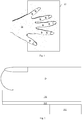
- the Fig. 1 schematically describes an example of a fingerprint capture system using the method according to the invention.
- a plurality of fingers of a hand M is placed on a fingerprint capture system 10.
- the Fig. 2 schematically illustrates in detail the fingerprint capture system 10.
- the fingerprint capture system 10 comprises a transparent blade 100 comprising an upper face on which the plurality of fingers are placed, of which only one finger D is shown in the figure. Fig. 2 .
- the fingerprint capture system 10 Located below the transparent slide 100 and glued to the underside of said slide, the fingerprint capture system 10 comprises a TCM 101 sensor.
- the TCM 101 sensor is positioned so as to generate an image of the plurality of fingers.
- the fingerprint capture system 10 further comprises a processing module 102.
- the Fig. 3 schematically illustrates an example of the hardware architecture of the processing module 102.
- the processing module 102 then comprises, connected by a communication bus 1020: a processor or CPU (“Central Processing Unit” in English) 1021; a random access memory RAM (“Random Access Memory” in English) 1022; a ROM read only memory 1023; a storage unit such as a hard disk or a storage medium reader, such as an SD (“Secure Digital”) 1024 card reader; at least one communication interface 1025 allowing the processing module 102 to receive the images acquired by the image sensor 101.
- a communication bus 1020 a processor or CPU (“Central Processing Unit” in English) 1021; a random access memory RAM (“Random Access Memory” in English) 1022; a ROM read only memory 1023; a storage unit such as a hard disk or a storage medium reader, such as an SD (“Secure Digital”) 1024 card reader; at least one communication interface 1025 allowing the processing module 102 to receive the images acquired by the image sensor 101.
- a communication bus 1020 a processor or CPU (“Central Processing Unit” in English) 1021
- Processor 1021 is capable of executing instructions loaded into RAM 1022 from ROM 1023, external memory (not shown), storage media (such as an SD card), or a communication network. When processing module 102 is powered on, processor 1021 is able to read instructions from RAM 1022 and execute them. These instructions form a computer program causing the implementation, by the processor 1021, of the method described in relation to the Fig. 4 .
- the process described in relation to the Fig. 4 can be implemented in software form by executing a set of instructions by a programmable machine, for example a DSP (“Digital Signal Processor”), a microcontroller or a GPU (graphics processor, “Graphics Processing Unit” in terminology Anglo-Saxon), or be implemented in hardware form by a machine or a dedicated component, for example an FPGA (“Field-Programmable Gate Array”) or an ASIC (“Application-Specific Integrated Circuit”).
- a programmable machine for example a DSP (“Digital Signal Processor”), a microcontroller or a GPU (graphics processor, “Graphics Processing Unit” in terminology Anglo-Saxon), or be implemented in hardware form by a machine or a dedicated component, for example an FPGA (“Field-Programmable Gate Array”) or an ASIC (“Application-Specific Integrated Circuit”).
- the Fig. 4 schematically illustrates an example of a method for obtaining images according to the invention.
- the image sensor 101 makes image acquisitions with a predefined image acquisition frequency F.
- a user wishes to be identified or authenticated, he applies a plurality of fingers to the upper face of the transparent blade 100.
- a triggering device not shown in FIG. Fig. 2 then triggers an acquisition of a sequence of images.
- the trigger device is, for example, a button that the user presses when he puts his hand on the upper face of the transparent slide 100 or a photoelectric cell which triggers the acquisition of the sequence of images when a presence at least one finger is detected on said upper face.
- the trigger device starts a timer which measures a duration d since the acquisition of the first image of a sequence of images.
- each segmented image supplied by the image sensor, and therefore the first segmented image represents each region identified by the segmentation process in the form of a mask, each pixel of a mask being represented by a same value different from a value assigned to the background pixels of the segmented image.
- the segmented image is a grayscale image where each pixel is coded on “8” bits between “0” and “255”
- each pixel of the background of the segmented image is for example associated with the value “ 0 "
- each pixel in a region is associated with the value" 200 ".
- the pixels of two distinct regions are associated with different values.
- the processing module 102 obtains an image, called a second segmented image, resulting from an application of the image segmentation method to a second image, called a second acquired image, according to the first acquired image.
- the processing module 102 applies a region tracking method to the regions identified in each segmented image from the first segmented image to the second segmented image.
- a region tracking method As we can read in the document “A. Yilmaz, O. Javed and M. Shah,“ Object tracking: a survey ”, ACM computing Surveys, Vol. 38, 2006 ” the literature abounds in object tracking methods ( ie tracking regions).
- the processing module 102 applies a method based on Kalman filtering. Kalman filtering is described in the document “RE Kalman, A new approach for linear filtering and prediction problems, journal of basic engineering, vol. 82, 1960, P. 33-45 " .
- the processing module uses a method described in the document “N.
- the processing module applies a method based on a descent of gradients described in the document "M. Bertalmio, G. Sapiro, G.
- Region tracking determines, among the regions identified in the second segmented image, which regions have a corresponding region in one or more previous segmented images of the image sequence.
- Certain regions can thus be followed over the whole sequence from the first segmented image to the second segmented image, others may appear only in certain images. This is for example the case when a finger is not pressed on the upper face of the transparent slide 100 with equal force during the acquisition of the images of the sequence.
- Step 43 for each region of the second segmented image having no corresponding region in a previous segmented image, called a new region, the processing module determines that the new region corresponds to a region found in a previous segmented image , said existing region, if a criterion representative of a correlation between the new region and at least one existing region is met. Step 43 therefore addresses any defects in the region tracking method. Indeed, regions of the second segmented image which would not have been associated with previous segmented image regions by the region tracking method can still be associated with previous segmented image regions.
- the processing module considers that the existing region is present in the second segmented image. It is therefore as if the existing region had been tracked by the region tracking method in the second segmented image.
- the processing module 102 considers that the new region corresponds to the existing region.
- C1 0.5, that is to say that the two regions must have at least 50% of area in common to be matched.
- a measure of correlation between a new region and an existing region is a function of a distance c2 between a center of gravity of the new region and a center of gravity of the existing region.
- the processing module 102 considers that the new region corresponds to the existing region.
- the distance threshold C2 10 pixels.
- the processing module 102 uses an overall measurement CG taking into account the ratio c1 and the distance c2 .
- the processing module 102 considers that the new region corresponds to the existing region.
- Step 43 makes it possible to process cases where the same finger is segmented with one, two or three phalanges depending on the images.
- the region tracking method then has difficulty tracking even though it is the same finger.
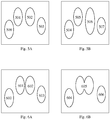
- Figs. 5A and 5B schematically illustrate a first case where a region tracking method might fail when matching regions.
- the Fig. 5A illustrates a first segmented image in which four regions have been detected by the segmentation process.
- the Fig. 5B illustrates a second segmented image directly following the first segmented image in which four regions have also been detected by the segmentation process.
- the region tracking method is capable of mapping region 500 to region 504, the region 501 with the region 505 and the region 503 with the region 507.
- the region tracking method is not capable of associating the region 502 with the region 506 because these two regions, although corresponding on the same finger, are very different.
- the region 506 in fact corresponds to two phalanges of the finger while the region 502 corresponds only to one phalanx. In this case, step 43 allows region 506 to be associated with region 502. Region 502 is then considered to be present in the second image.
- Figs. 6A and 6B schematically illustrate a second case where a region tracking method might fail when matching regions.
- the Fig. 6A illustrates a third segmented image in which four regions have been detected by the segmentation process.
- the Fig. 6B illustrates a fourth segmented image directly following the third segmented image. Only three regions were detected in the fourth image.
- the tracking method is able to map region 600 to region 604 and region 603 to region 606. But the tracking method is not able to map regions 601 and 602 to region 605. This problem occurs when two fingers are very close and their proximity induces the segmentation process in error since it does not know in this case whether it is dealing with one or two regions.
- step 43 makes it possible to associate region 605 with both region 601 and region 602. Regions 601 and 602 are then considered to be present in the fourth image.
- Step 42, or step 43 when executed, is followed by step 45.
- the processing module 102 determines a confidence score ⁇ curr for each region identified in each segmented image, the confidence score ⁇ curr for a region of the second segmented image (ie the segmented image current) associated with a region of a previous segmented image being a sum between the confidence score of said region of the previous image ⁇ pre and of a first increment ⁇ 1 ( F ) depending on the image acquisition frequency predefined F.
- ⁇ curr ⁇ pre + ⁇ 1 F
- the first increment is a decreasing function of the predefined image acquisition frequency F.
- ⁇ 1 F K 1 F
- K1 is a constant, for example equal to "2".
- step 45 the note of confidence ⁇ curr an identified region in at least one previous segmented image but having no corresponding region in the second segmented image (i. E. The current segmented image) , is a difference between the confidence score of said region of the previous image ⁇ pre and of a second increment ⁇ 2 ( F ) depending on the predefined image acquisition frequency F.
- ⁇ curr ⁇ pre - ⁇ 2 F
- the second increment is also a decreasing function of the predefined image acquisition frequency F.
- ⁇ 2 F K 2 F
- K2 is a constant, for example equal to “1”.
- a region which is present in each image of the sequence sees its rating increase more rapidly than a region which does not appear in certain images of the sequence.
- the confidence score of said new region is initialized at zero when this region is identified by the segmentation process.
- the processing module 102 determines a number N of regions, called admissible regions, identified in the segmented images from the first segmented image to the second segmented image ( ie current segmented image) having a higher confidence score. at a predetermined confidence threshold S1 .
- the predetermined confidence threshold S1 is equal to “1.5”.
- the processing module 102 compares the number of admissible regions N with a predetermined number of regions S2. When the number of admissible regions N is equal to the predetermined number of regions S2, the processing module 102 terminates the image acquisitions and generates information making it possible to obtain an image, called the final image, comprising, for each admissible region, a zone of an acquired image corresponding to the admissible region during a step 49. In one embodiment, the information generated is directly the final image. To generate the final image, the processing module 102 determines in which segmented image each of the S2 regions has obtained a maximum confidence score.
- the processing module 102 extracts from the acquired image corresponding to the segmented image, the pixels located in an area corresponding spatially to the region of the segmented image and inserts them into the final image at the same position. Pixels in the final image that do not correspond to a region are set to a preset value. The final image therefore represents fingerprints on a uniform background.
- the information generated comprises information representative of a set of pointers indicating for each pixel to be used to generate the final image, the acquired image in which to fetch said pixel and the position of said pixel in said pixel. image acquired.
- the processing module 102 compares the duration d since the acquisition of the first acquired image with a predetermined duration D corresponding to a maximum acquisition time.
- the predetermined duration D corresponds to a maximum time during which a user must leave his hand in the fingerprint capture system 10. In one embodiment, the predetermined duration D is “2” seconds. If the duration d is less than or equal to the predetermined duration D, the processing module 102 returns to step 41 during which it obtains a new second segmented image.
- the processing module 102 ends the image acquisitions and generates a final image with the regions that it has at its disposal.
- the final image then comprises a number of zones at most equal to the predetermined number of regions S2 , each zone corresponding to a region identified in the images segmented from the first segmented image to the second segmented image, each region used to define a zone having a higher confidence score than the confidence scores of the zones not used to define a zone.
- the processing module chooses a maximum of regions among the regions identified in the segmented images, without exceeding the predetermined number of regions S2.
- the chosen regions are the regions identified in the segmented images associated with the highest confidence scores. Among these selected regions, some regions may have a confidence score greater than the S1 confidence threshold, and others, a confidence score less than the S1 confidence threshold.
Landscapes
- Engineering & Computer Science (AREA)
- Physics & Mathematics (AREA)
- General Physics & Mathematics (AREA)
- Multimedia (AREA)
- Theoretical Computer Science (AREA)
- Human Computer Interaction (AREA)
- Optics & Photonics (AREA)
- Image Input (AREA)
- Collating Specific Patterns (AREA)
Description
L'invention concerne un procédé permettant d'obtenir une image d'au moins une empreinte digitale à partir d'une pluralité d'images acquises par un capteur d'images d'un système de capture d'empreintes digitales et un dispositif mettant en œuvre le procédé.The invention relates to a method for obtaining an image of at least one fingerprint from a plurality of images acquired by an image sensor of a fingerprint capture system and a device for implementing the image. implement the process.
L'utilisation d'empreintes digitales, par exemple du type empreinte d'un doigt, d'une pluralité de doigts, d'une paume de main, permet de sécuriser des accès à des bâtiments ou à des machines. Utiliser cette technologie permet de renforcer la sécurité dans la mesure où la probabilité que deux personnes aient deux empreintes digitales identiques est quasiment nulle.The use of fingerprints, for example of the fingerprint type, of a plurality of fingers, of a palm of a hand, makes it possible to secure access to buildings or to machines. Using this technology increases security as the probability that two people have two identical fingerprints is almost zero.
Un système de capture d'empreintes digitales permet d'obtenir au moins une image d'au moins une empreinte digitale. Dans le cas d'une identification, chaque empreinte est comparée avec un ensemble d'empreintes digitales de référence contenues dans une base de données. Dans le cas d'une authentification, chaque empreinte est comparée à une seule empreinte digitale. La comparaison permet de déterminer si chaque empreinte digitale obtenue appartient ou non à une personne référencée dans la base de données ou si la personne est bien celle qu'elle prétend être.A fingerprint capture system makes it possible to obtain at least one image of at least one fingerprint. In the case of identification, each fingerprint is compared with a set of reference fingerprints contained in a database. In the case of authentication, each fingerprint is compared to a single fingerprint. The comparison makes it possible to determine whether or not each obtained fingerprint belongs to a person referenced in the database or if the person is indeed who he claims to be.
Certains systèmes de capture d'empreintes digitales capturent une séquence d'images d'empreintes. C'est notamment le cas de certains systèmes de capture d'empreintes digitales par contact qui ne sont pas configurés pour assurer une stabilité du (ou des) doigt(s) devant le capteur d'images ou pas configurés pour que chaque doigt soit appuyé de la même manière et au même moment sur le système de capture d'empreintes digitales. C'est aussi le cas des systèmes de capture d'empreintes digitales sans contact devant lesquels on fait passer le (ou les) doigt(s) sans qu'aucun doigt ne touche ledit système. Durant la capture d'images, chaque doigt est en mouvement devant le capteur d'images. Ce type de système de capture d'images utilise alors un procédé d'obtention d'images permettant d'obtenir une image finale à partir des images de la séquence. L'image finale correspond soit à l'image de la séquence représentant au mieux chaque empreinte digitale, soit à des portions d'images de la séquence, chaque portion représentant au mieux une empreinte.Some fingerprint capture systems capture a sequence of fingerprint images. This is particularly the case with certain contact fingerprint capture systems which are not configured to ensure stability of the finger (s) in front of the image sensor or not configured so that each finger is pressed. in the same way and at the same time on the fingerprint capture system. This is also the case with contactless fingerprint capture systems in front of which the finger (s) are passed without any finger touching said system. During image capture, each finger is moving in front of the image sensor. This type of image capture system then uses a process for obtaining images making it possible to obtain a final image from the images of the sequence. The final image corresponds either to the image of the sequence best representing each fingerprint, or to portions of images of the sequence, each portion best representing a fingerprint.
Bon nombre de systèmes de capture d'empreintes digitales actuels utilisent des capteurs d'images, dits capteurs optiques, tels que les capteurs d'images de type CCD (dispositif à transfert de charge, « charge-coupled device » en terminologie anglo-saxonne) ou CMOS (semiconducteur metal-oxyde complémentaires, « complementary metal-oxide-semiconductor » en terminologie anglo-saxonne). D'autres types de capteurs d'images tels que les capteurs d'images de type TCM (transistors en couches minces, « thin-film transistors (TFT) » en terminologie anglo-saxonne), dits capteurs TCM, pourraient avantageusement être utilisés dans les systèmes de capture d'empreintes digitales.A good number of current fingerprint capture systems use image sensors, known as optical sensors, such as image sensors of the CCD type (charge-coupled device, in English terminology. ) or CMOS (complementary metal-oxide semiconductor, “complementary metal-oxide-semiconductor” in English terminology). Other types of image sensors such as image sensors of the TCM type (thin-film transistors (TFT) "in English terminology), called TCM sensors, could advantageously be used in fingerprint capture systems.
Les images acquises par un capteur d'images ont des propriétés différentes suivant le type de capteur d'images utilisé. Ainsi un capteur optique possède une fréquence d'acquisition d'images plus faible qu'un capteur TCM. Mais, les images acquises par un capteur optique, du fait de leur temps d'acquisition plus important, sont de qualité supérieure aux images acquises par un capteur TCM.The images acquired by an image sensor have different properties depending on the type of image sensor used. Thus an optical sensor has a lower image acquisition frequency than a TCM sensor. However, the images acquired by an optical sensor, because of their longer acquisition time, are of higher quality than the images acquired by a TCM sensor.
Les procédés d'obtention d'images utilisés par les systèmes de capture d'empreintes digitales capturant une séquence d'images d'empreintes sont en général adaptés aux caractéristiques du capteur d'image utilisés par ledit système. Ces procédés sont notamment adaptés à la fréquence d'acquisition d'images de ces capteurs. Ainsi un procédé destiné à fonctionner avec des images fournies par un capteur optique (respectivement un capteur TCM), ne peut fonctionner correctement avec des images fournies par un capteur TCM (respectivement un capteur optique).The methods for obtaining images used by the fingerprint capture systems capturing a sequence of fingerprint images are generally adapted to the characteristics of the image sensor used by said system. These methods are in particular adapted to the image acquisition frequency of these sensors. Thus, a method intended to operate with images supplied by an optical sensor (respectively a TCM sensor) cannot function correctly with images supplied by a TCM sensor (respectively an optical sensor).
Il est souhaitable de pallier ces inconvénients de l'état de la technique. Il est notamment souhaitable de proposer un procédé d'obtention d'images qui puisse s'adapter à tout type de capteurs d'images utilisé.It is desirable to overcome these drawbacks of the state of the art. It is in particular desirable to provide a method for obtaining images which can be adapted to any type of image sensor used.
Selon un premier aspect de l'invention, l'invention concerne un procédé permettant d'obtenir une image d'au moins une empreinte digitale à partir d'une séquence d'images acquises par un capteur d'images d'un système de capture d'empreintes digitales faisant des acquisitions d'images avec une fréquence d'acquisition d'images prédéfinie dépendante dudit capteur d'images. Le procédé comprend : obtenir une image, dite première image segmentée, résultant d'une application d'un procédé de segmentation d'images sur une première image acquise, ledit procédé de segmentation étant adapté pour identifier des régions correspondant à des empreintes dans une image; pour chaque image acquise, dite seconde image acquise, suivant la première image acquise appliquer un traitement comprenant: obtenir une image, dite seconde image segmentée, résultant d'une application du procédé de segmentation d'images à la seconde image acquise; appliquer un procédé de suivi de régions aux régions identifiées dans chaque image segmentée depuis la première image segmentée jusqu'à la seconde image segmentée ; déterminer une note de confiance pour chaque région identifiée, la note de confiance d'une région de la seconde image segmentée associée à une région d'une image segmentée précédente étant une somme entre la note de confiance de ladite région de l'image précédente et d'un incrément dépendant de la fréquence d'acquisition d'images prédéfinie, et la note de confiance d'une région identifiée dans au moins une image segmentée précédant la seconde image segmentée mais n'ayant pas de région correspondante dans la seconde image segmentée étant une différence entre la note de confiance de ladite région de l'image segmentée précédente et d'un deuxième incrément dépendant de la fréquence d'acquisition d'images prédéfinie et, déterminer un nombre de régions, dites régions admissibles, identifiées dans les images segmentées depuis la première image segmentée jusqu'à la deuxième image segmentée ayant une note de confiance supérieure à un premier seuil prédéterminé ; et, lorsque le nombre de régions admissibles est égal à un deuxième seuil prédéterminé, mettre fin aux acquisitions d'images et générer une information permettant d'obtenir une image comprenant, pour chaque région admissible, une zone d'une image acquise correspondant à la région admissible.According to a first aspect of the invention, the invention relates to a method making it possible to obtain an image of at least one fingerprint from a sequence of images acquired by an image sensor of a capture system. of fingerprints making image acquisitions with a predefined image acquisition frequency dependent on said image sensor. The method comprises: obtaining an image, called a first segmented image, resulting from an application of an image segmentation method on a first acquired image, said segmentation method being adapted to identify regions corresponding to fingerprints in an image; for each acquired image, called second acquired image, following the first acquired image, apply a processing comprising: obtaining an image, called second segmented image, resulting from an application of the image segmentation process to the second acquired image; applying a region tracking method to the regions identified in each segmented image from the first segmented image to the second segmented image; determining a confidence score for each region identified, the confidence score of a region of the second segmented image associated with a region of a previous segmented image being a sum between the confidence score of said region of the previous image and an increment depending on the predefined image acquisition frequency, and the confidence score of a region identified in at least one segmented image preceding the second segmented image but having no corresponding region in the second segmented image being a difference between the confidence score of said region of the previous segmented image and of a second increment depending on the predefined image acquisition frequency and, determining a number of regions, called admissible regions, identified in the images segmented from the first segmented image to the second segmented image having a confidence score greater than a first predetermined threshold; and, when the number of admissible regions is equal to a second predetermined threshold, terminating the image acquisitions and generating information making it possible to obtain an image comprising, for each admissible region, a zone of an acquired image corresponding to the eligible region.
Le procédé permet donc d'adapter l'évolution de la note de confiance de chaque région en fonction de la fréquence d'acquisition d'images. De cette manière, le procédé permettant d'obtenir une image est adapté à n'importe quel type de capteur d'images.The method therefore makes it possible to adapt the evolution of the confidence score of each region as a function of the image acquisition frequency. In this way, the method for obtaining an image is suitable for any type of image sensor.
Ainsi, la note de confiance d'une région détectée dans une image segmentée précédente croit lorsque ladite région est détectée dans la seconde image segmentée et décroit lorsque ladite région n'est pas détectée dans la seconde image segmentée.Thus, the confidence score of a region detected in a previous segmented image increases when said region is detected in the second segmented image and decreases when said region is not detected in the second segmented image.
Selon un mode de réalisation, pour chaque région de la seconde image segmentée n'ayant pas de région correspondante dans une image segmentée précédente, dite nouvelle région, déterminer que la nouvelle région correspond à une région trouvée dans une image segmentée précédente, dite région existante, si un critère représentatif d'une corrélation entre la nouvelle région et au moins une région existante est respecté.According to one embodiment, for each region of the second segmented image having no corresponding region in a previous segmented image, called a new region, determining that the new region corresponds to a region found in a previous segmented image, called an existing region , if a criterion representative of a correlation between the new region and at least one existing region is met.
Ainsi, si le procédé de suivi de région ne permet pas de suivre une région détectée dans une image segmentée précédente dans la seconde image segmentée, il est possible de déterminer par une méthode alternative si cette région est présente dans la seconde image segmentée.Thus, if the region tracking method does not make it possible to track a region detected in a previous segmented image in the second segmented image, it is possible to determine by an alternative method whether this region is present in the second segmented image.
Selon un mode de réalisation, le critère représentatif d'une corrélation entre une nouvelle région et une région existante est fonction d'un rapport entre une surface d'une intersection entre la région existante et la nouvelle région et une valeur minimum de surface entre la surface de la nouvelle région et la surface de la région existante et/ou fonction d'une distance entre un centre de gravité de la nouvelle région et un centre de gravité de la région existante.According to one embodiment, the criterion representative of a correlation between a new region and an existing region is a function of a ratio between an area of an intersection between the existing region and the new region and a minimum area value between the area of the new region and the area of the existing region and / or a function of a distance between a center of gravity of the new region and a center of gravity of the existing region.
Selon un mode de réalisation, lorsque le nombre de régions admissibles est inférieur au deuxième seuil prédéterminé, appliquer le traitement pour une nouvelle seconde image acquise si une durée depuis l'acquisition de la première image acquise est inférieure ou égale à une durée prédéterminée.According to one embodiment, when the number of admissible regions is less than the second predetermined threshold, applying the processing for a new second acquired image if a duration since the acquisition of the first acquired image is less than or equal to a predetermined duration.
Selon un mode de réalisation, si la durée depuis l'acquisition de la première image acquise est supérieure à la durée prédéterminée, mettre fin aux acquisitions d'images et générer une information permettant de générer une image comprenant un nombre de zones d'images acquises au plus égal au deuxième seuil prédéterminé, chaque zone correspondant à une région identifiée dans les images segmentées depuis la première image segmentée jusqu'à la deuxième image segmentée, chaque région utilisée pour définir une zone ayant une note de confiance supérieure aux notes de confiance des zones non utilisées pour définir une zone.According to one embodiment, if the duration since the acquisition of the first acquired image is greater than the predetermined duration, terminate the image acquisitions and generate information making it possible to generate an image comprising a number of areas of acquired images. at most equal to the second predetermined threshold, each zone corresponding to a region identified in the images segmented from the first segmented image to the second segmented image, each region used to define an area having a confidence score greater than the confidence scores of the zones not used to define a zone.
Ainsi, le procédé a une durée maximum, ce qui permet d'éviter qu'un utilisateur reste trop longtemps devant le système de capture d'empreintes digitales. Le procédé permet malgré tout d'obtenir une information permettant de générer une image, même si certaines régions utilisées pour définir une zone de cette image ont une note de confiance insuffisante.Thus, the method has a maximum duration, which makes it possible to avoid that a user remains too long in front of the fingerprint capture system. The method nevertheless makes it possible to obtain information making it possible to generate an image, even if certain regions used to define a zone of this image have an insufficient confidence score.
Selon un mode de réalisation, chaque incrément est inversement proportionnel à la fréquence d'acquisition d'images prédéfinie.According to one embodiment, each increment is inversely proportional to the predefined image acquisition frequency.
Ainsi, la note de confiance d'une région issue d'un capteur ayant une faible fréquence d'acquisition évolue plus vite que la note de confiance d'une région issue d'un capteur ayant une fréquence d'acquisition plus élevée. Le nombre d'images nécessaires pour générer une information permettant d'obtenir une image comprenant, pour chaque région admissible, une zone d'une image acquise correspondant à la région admissible est donc plus faible lorsque le capteur d'images utilisé possède une fréquence d'acquisition d'images faible que lorsque le capteur d'images utilisé possède une fréquence d'acquisition d'images plus élevée.Thus, the confidence score of a region resulting from a sensor having a low acquisition frequency evolves faster than the confidence score of a region resulting from a sensor having a higher acquisition frequency. The number of images necessary to generate information making it possible to obtain an image comprising, for each admissible region, an area of an acquired image corresponding to the admissible region is therefore smaller when the image sensor used has an image acquisition frequency lower than when the image sensor used has a higher image acquisition frequency.
Selon un deuxième aspect de l'invention, l'invention concerne un dispositif permettant d'obtenir une image d'au moins une empreinte digitale à partir d'une séquence d'images acquises par un capteur d'images d'un système de capture d'empreintes digitales faisant des acquisitions d'images avec une fréquence d'acquisition d'images prédéfinie dépendante dudit capteur d'images. Le dispositif comprend : des moyens d'obtention pour obtenir une image, dite première image segmentée, résultant d'une application d'un procédé de segmentation d'images sur une première image acquise, ledit procédé de segmentation étant adapté pour identifier des régions correspondant à des empreintes dans une image; des moyens d'obtention pour obtenir au moins une image, dite seconde image segmentée, résultant d'une application du procédé de segmentation d'images à au moins une image acquise suivant la première image acquise, dite seconde image acquise; des moyens de traitement pour appliquer un procédé de suivi de régions aux régions identifiées dans chaque image segmentée depuis la première image segmentée jusqu'à la seconde image segmentée ; des moyens de traitement pour déterminer une note de confiance pour chaque région identifiée, la note de confiance d'une région de la seconde image segmentée associée à une région d'une image segmentée précédente étant une somme entre la note de confiance de ladite région de l'image précédente et d'un incrément dépendant de la fréquence d'acquisition d'images prédéfinie, et la note de confiance d'une région identifiée dans au moins une image segmentée précédant la seconde image segmentée mais n'ayant pas de région correspondante dans la seconde image segmentée étant une différence entre la note de confiance de ladite région de l'image segmentée précédente et d'un deuxième incrément dépendant de la fréquence d'acquisition d'images prédéfinie et, des moyens de traitement pour déterminer un nombre de régions, dites régions admissibles, identifiées dans les images segmentées depuis la première image segmentée jusqu'à la deuxième image segmentée ayant une note de confiance supérieure à un premier seuil prédéterminé ; et, des moyens de traitement pour mettre fin aux acquisitions d'images lorsque le nombre de régions admissibles est égal à un deuxième seuil prédéterminé, et pour générer une information permettant d'obtenir une image comprenant, pour chaque région admissible, une zone d'une image acquise correspondant à la région admissible.According to a second aspect of the invention, the invention relates to a device making it possible to obtain an image of at least one fingerprint from a sequence of images acquired by an image sensor of a capture system. of fingerprints making image acquisitions with a predefined image acquisition frequency dependent on said image sensor. The device comprises: obtaining means for obtaining an image, called a first segmented image, resulting from an application of an image segmentation method on a first acquired image, said segmentation method being adapted to identify corresponding regions to footprints in an image; obtaining means for obtaining at least one image, called second segmented image, resulting from an application of the image segmentation method to at least one image acquired according to the first image acquired, called second image acquired; processing means for applying a region tracking method to the regions identified in each segmented image from the first segmented image to the second segmented image; processing means for determining a confidence score for each identified region, the confidence score of a region of the second segmented image associated with a region of a previous segmented image being a sum between the confidence score of said region of the previous image and an increment depending on the predefined image acquisition frequency, and the confidence score of a region identified in at least one segmented image preceding the second segmented image but having no corresponding region in the second segmented image being a difference between the confidence score of said region of the previous segmented image and of a second increment depending on the predefined image acquisition frequency and, processing means for determining a number of regions, called admissible regions, identified in the segmented images from the first segmented image to the second segmented image having a confidence score greater than one p rst predetermined threshold; and, processing means for terminating the image acquisitions when the number of admissible regions is equal to a second predetermined threshold, and for generating information making it possible to obtain an image comprising, for each admissible region, a zone of an acquired image corresponding to the eligible region.
Selon un troisième aspect de l'invention, l'invention concerne un système comprenant un dispositif selon le deuxième aspect.According to a third aspect of the invention, the invention relates to a system comprising a device according to the second aspect.
Selon un quatrième aspect, l'invention concerne un programme d'ordinateur, comprenant des instructions pour mettre en œuvre, par un dispositif, le procédé selon le premier aspect, lorsque ledit programme est exécuté par un processeur dudit dispositif.According to a fourth aspect, the invention relates to a computer program, comprising instructions for implementing, by a device, the method according to the first aspect, when said program is executed by a processor of said device.
Selon un cinquième aspect, l'invention concerne des moyens de stockage, stockant un programme d'ordinateur comprenant des instructions pour mettre en œuvre, par un dispositif, le procédé selon le premier aspect, lorsque ledit programme est exécuté par un processeur dudit dispositif.According to a fifth aspect, the invention relates to storage means, storing a computer program comprising instructions for implementing, by a device, the method according to the first aspect, when said program is executed by a processor of said device.
Les caractéristiques de l'invention mentionnées ci-dessus, ainsi que d'autres, apparaîtront plus clairement à la lecture de la description suivante d'un exemple de réalisation, ladite description étant faite en relation avec les dessins joints, parmi lesquels :
- la
Fig. 1 décrit schématiquement un exemple de système de capture d'empreintes digitales utilisant le procédé selon l'invention ; - la
Fig. 2 illustre schématiquement de manière détaillée le système de capture d'empreintes digitales ; - la
Fig. 3 illustre schématiquement un exemple d'architecture matérielle d'un module de traitement mettant en œuvre le procédé selon l'invention ; - la
Fig. 4 illustre schématiquement un exemple de procédé permettant d'obtenir des images selon l'invention ; - Les
Figs. 5A et 5B illustrent schématiquement un premier cas où un procédé de suivi de régions pourrait échouer lors d'une mise en correspondance de régions ; et, - Les
Figs. 6A et 6B illustrent schématiquement un deuxième cas où un procédé de suivi de régions pourrait échouer lors d'une mise en correspondance de régions.
- the
Fig. 1 schematically describes an example of a fingerprint capture system using the method according to the invention; - the
Fig. 2 schematically illustrates in detail the fingerprint capture system; - the
Fig. 3 schematically illustrates an example of the hardware architecture of a processing module implementing the method according to the invention; - the
Fig. 4 schematically illustrates an example of a method for obtaining images according to the invention; - The
Figs. 5A and 5B schematically illustrate a first case where a region tracking method could fail during region matching; and, - The
Figs. 6A and 6B schematically illustrate a second case where a region tracking method might fail when matching regions.
Le procédé de l'invention est décrit dans un contexte où un système de capture d'empreintes digitales par contact utilisant un capteur TCM fait des acquisitions d'images d'une pluralité de doigts. Le procédé est toutefois adapté pour fonctionner avec un système de capture d'empreintes digitales par contact utilisant un capteur optique ou un système de capture d'empreintes digitales sans contact utilisant un capteur optique ou un capteur TCM.The method of the invention is described in a context where a contact fingerprint capture system using a TCM sensor acquires images of a plurality of fingers. The method is however adapted to operate with a contact fingerprint capture system using an optical sensor or a non-contact fingerprint capture system using an optical sensor or TCM sensor.
La
Dans la
La
Le système de capture d'empreintes digitales 10 comprend une lame transparente 100 comprenant une face supérieure sur laquelle est posée la pluralité de doigts, dont seul un doigt D est représenté dans la
La
Selon l'exemple d'architecture matérielle représenté à la
Le processeur 1021 est capable d'exécuter des instructions chargées dans la RAM 1022 à partir de la ROM 1023, d'une mémoire externe (non représentée), d'un support de stockage (tel qu'une carte SD), ou d'un réseau de communication. Lorsque le module de traitement 102 est mis sous tension, le processeur 1021 est capable de lire de la RAM 1022 des instructions et de les exécuter. Ces instructions forment un programme d'ordinateur causant la mise en œuvre, par le processeur 1021, du procédé décrit en relation avec la
Le procédé décrit en relation avec la
La
Le capteur d'images 101 fait des acquisitions d'images avec une fréquence d'acquisition d'image prédéfinie F. Lorsqu'un utilisateur souhaite se faire identifier ou authentifier, il applique une pluralité de doigts sur la face supérieure de la lame transparente 100. Un dispositif de déclenchement non représenté dans la
En même temps qu'il déclenche l'acquisition de la séquence d'image, le dispositif de déclenchement démarre un minuteur qui mesure une durée d depuis l'acquisition de la première image d'une séquence d'images.At the same time as it triggers the acquisition of the image sequence, the trigger device starts a timer which measures a duration d since the acquisition of the first image of a sequence of images.
Dans une étape 40, le module de traitement 102 obtient une image, dite première image segmentée, résultant d'une application d'un procédé de segmentation d'images sur une première image acquise par le capteur d'images 101. Le procédé de segmentation est adapté pour identifier des régions correspondant à des empreintes dans une image. Le procédé de segmentation est par exemple un procédé décrit dans le document
Dans un mode de réalisation, chaque image segmentée fournie par le capteur d'images, et donc la première image segmentée, représente chaque région identifiée par le procédé de segmentation sous forme d'un masque, chaque pixel d'un masque étant représenté par une même valeur différente d'une valeur attribuée aux pixels du fond de l'image segmentée. En supposant que l'image segmentée est une image de niveaux de gris où chaque pixel est codé sur « 8 » bits entre « 0 » et « 255 », chaque pixel du fond de l'image segmentée est par exemple associé à la valeur « 0 », et chaque pixel d'une région est associé à la valeur « 200 ». Dans un mode de réalisation, les pixels de deux régions distinctes sont associés à des valeurs différentes.In one embodiment, each segmented image supplied by the image sensor, and therefore the first segmented image, represents each region identified by the segmentation process in the form of a mask, each pixel of a mask being represented by a same value different from a value assigned to the background pixels of the segmented image. Assuming that the segmented image is a grayscale image where each pixel is coded on “8” bits between “0” and “255”, each pixel of the background of the segmented image is for example associated with the value “ 0 ", and each pixel in a region is associated with the value" 200 ". In one embodiment, the pixels of two distinct regions are associated with different values.
Dans une étape 41, le module de traitement 102 obtient une image, dite seconde image segmentée, résultant d'une application du procédé de segmentation d'images à une seconde image, dite seconde image acquise, suivant la première image acquise.In a
Dans une étape 42, le module de traitement 102 applique un procédé de suivi de régions aux régions identifiées dans chaque image segmentée depuis la première image segmentée jusqu'à la seconde image segmentée. Comme on peut le lire dans le document
Dans une étape 43 optionnelle, pour chaque région de la seconde image segmentée n'ayant pas de région correspondante dans une image segmentée précédente, dite nouvelle région, le module de traitement détermine que la nouvelle région correspond à une région trouvée dans une image segmentée précédente, dite région existante, si un critère représentatif d'une corrélation entre la nouvelle région et au moins une région existante est respecté. L'étape 43 vient donc palier des éventuels défauts du procédé de suivi de régions. En effet, des régions de la seconde image segmentée qui n'auraient pas été associées à des régions d'images segmentées précédentes par le procédé de suivi de régions peuvent quand même être associées à des régions d'images segmentées précédentes. Lorsque le critère de corrélation est respecté entre une nouvelle région et une région existante, le module de traitement considère que la région existante est présente dans la seconde image segmentée. Tout se passe donc comme si la région existante avait été suivie par le procédé de suivi de région dans la seconde image segmentée.In an
Dans un mode de réalisation, un critère de corrélation entre une nouvelle région et une région existante, est fonction d'un rapport c1 entre une surface d'une intersection entre les deux régions et une valeur minimum de surface entre la surface de la nouvelle région et la surface de la région existante : ![]()
![]()
Ainsi, si la mesure c1>C1, ou C1 est un seuil prédéterminé, le module de traitement 102 considère que la nouvelle région correspond à la région existante. Dans un mode de réalisation C1=0.5, c'est-à-dire que les deux régions doivent avoir au moins 50% de surface en commun pour être mises en correspondance.Thus, if the measurement c1> C1 , or C1 is a predetermined threshold, the
Dans un mode de réalisation, une mesure de corrélation entre une nouvelle région et une région existante, est fonction d'une distance c2 entre un centre de gravité de la nouvelle région et un centre de gravité de la région existante. Ainsi, si la distance c2<C2, ou C2 est un seuil de distance prédéterminé, le module de traitement 102 considère que la nouvelle région correspond à la région existante. Dans un mode de réalisation, le seuil de distance C2=10 pixels.In one embodiment, a measure of correlation between a new region and an existing region is a function of a distance c2 between a center of gravity of the new region and a center of gravity of the existing region. Thus, if the distance c2 <C2, or C2 is a predetermined distance threshold, the
Dans un mode de réalisation, le module de traitement 102 utilise une mesure globale CG prenant en compte le rapport c1 et la distance c2. Par exemple la mesure globale CG est la suivante : ![]()
![]()
L'étape 43 permet de traiter des cas où un même doigt est segmenté avec une, deux ou trois phalanges suivant les images. Le procédé de suivi de région a alors du mal à effectuer le suivi bien que cela soit le même doigt.
Les
La
Les
La
L'étape 42, ou l'étape 43 lorsqu'elle est exécutée, est suivie d'une étape 45.
Au cours de l'étape 45, le module de traitement 102 détermine une note de confiance θcurr pour chaque région identifiée dans chaque image segmentée, la note de confiance θcurr d'une région de la seconde image segmentée (i.e. l'image segmentée courante) associée à une région d'une image segmentée précédente étant une somme entre la note de confiance de ladite région de l'image précédente θpre et d'un premier incrément Δ1(F) dépendant de la fréquence d'acquisition d'images prédéfinie F. ![]()
![]()
Le premier incrément est une fonction décroissante de la fréquence d'acquisition d'images prédéfinie F. Par exemple : ![]()
![]()
Au cours de l'étape 45, la note de confiance θcurr d'une région identifiée dans au moins une image segmentée précédente mais n'ayant pas de région correspondante dans la seconde image segmentée (i.e. l'image segmentée courante), est une différence entre la note de confiance de ladite région de l'image précédente θpre et d'un deuxième incrément Δ2(F) dépendant de la fréquence d'acquisition d'images prédéfinie F. ![]()
![]()
Le deuxième incrément est lui aussi une fonction décroissante de la fréquence d'acquisition d'images prédéfinie F. Par exemple : ![]()
![]()
Ainsi, une région qui est présente dans chaque image de la séquence voit sa note augmenter plus rapidement qu'une région qui n'apparaît pas dans certaines images de la séquence.Thus, a region which is present in each image of the sequence sees its rating increase more rapidly than a region which does not appear in certain images of the sequence.
On note que pour chaque nouvelle région qui apparaît dans une image segmentée mais qui n'a pas de région correspondante dans une image segmentée précédente, la note de confiance de ladite nouvelle région est initialisée à zéro lorsque cette région est identifiée par le procédé de segmentation.Note that for each new region which appears in a segmented image but which does not have a corresponding region in a previous segmented image, the confidence score of said new region is initialized at zero when this region is identified by the segmentation process. .
Dans une étape 46, le module de traitement 102 détermine un nombre N de régions, dites régions admissibles, identifiées dans les images segmentées depuis la première image segmentée jusqu'à la deuxième image segmentée (i.e. image segmentée courante) ayant une note de confiance supérieure à un seuil de confiance prédéterminé S1. Par exemple, dans un mode de réalisation, le seuil de confiance prédéterminé S1 est égal à « 1.5 ».In a
Dans une étape 47, le module de traitement 102 compare le nombre de régions admissibles N avec un nombre de régions prédéterminé S2. Lorsque le nombre de régions admissibles N est égal au nombre de régions prédéterminé S2, le module de traitement 102 met fin aux acquisitions d'images et génère une information permettant d'obtenir une image, dite image finale, comprenant, pour chaque région admissible, une zone d'une image acquise correspondant à la région admissible lors d'une étape 49. Dans un mode de réalisation, l'information générée est directement l'image finale. Pour générer l'image finale, le module de traitement 102 détermine dans quelle image segmentée chacune des S2 régions a obtenu une note de confiance maximale. Lorsque, pour chaque région, une image segmentée a été déterminée, le module de traitement 102 extrait de l'image acquise correspondant à l'image segmentée, les pixels situés dans une zone correspondant spatialement à la région de l'image segmentée et les insère dans l'image finale à la même position. Les pixels de l'image finale qui ne correspondent pas à une région sont mis à une valeur prédéfinie. L'image finale représente donc des empreintes sur un fond uniforme.In a step 47, the
Dans un mode de réalisation, l'information générée comprend une information représentative d'un ensemble de pointeurs indiquant pour chaque pixel à utiliser pour générer l'image finale, l'image acquise dans laquelle aller chercher ledit pixel et la position dudit pixel dans ladite image acquise.In one embodiment, the information generated comprises information representative of a set of pointers indicating for each pixel to be used to generate the final image, the acquired image in which to fetch said pixel and the position of said pixel in said pixel. image acquired.
Lorsque le nombre de régions admissibles N est inférieur au nombre de régions prédéterminé S2, le module de traitement 102 compare la durée d depuis l'acquisition de la première image acquise à une durée D prédéterminée correspondant à un temps d'acquisition maximum. La durée prédéterminée D correspond à un temps maximum durant lequel un utilisateur doit laisser sa main dans le système de capture d'empreintes digitales 10. Dans un mode de réalisation, la durée prédéterminée D est de « 2 » secondes. Si la durée d est inférieure ou égale à la durée prédéterminée D, le module de traitement 102 retourne à l'étape 41 au cours de laquelle il obtient une nouvelle seconde image segmentée.When the number of admissible regions N is less than the predetermined number of regions S2, the
Si d > D, lors de l'étape 49, le module de traitement 102 met fin aux acquisitions d'images et génère une image finale avec les régions qu'il a à sa disposition. L'image finale comprend alors un nombre de zones au plus égal au nombre de régions prédéterminé S2, chaque zone correspondant à une région identifiée dans les images segmentées depuis la première image segmentée jusqu'à la deuxième image segmentée, chaque région utilisée pour définir une zone ayant une note de confiance supérieure aux notes de confiance des zones non utilisées pour définir une zone. En d'autres termes, le module de traitement choisit un maximum de régions parmi les régions identifiées dans les images segmentées, sans dépasser le nombre de régions prédéterminé S2. Les régions choisies sont les régions identifiées dans les images segmentées associées aux notes de confiance les plus élevées. Parmi ces régions choisies, certaines régions peuvent avoir une note de confiance supérieure au seuil de confiance S1, et d'autres, une note de confiance inférieure au seuil de confiance S1.If d> D, during
Claims (10)
- Method for obtaining an image of at least one fingerprint from a sequence of images acquired by an image sensor of a fingerprint capture system (10) making acquisitions of images with a predefined image acquisition frequency dependent on said image sensor, characterized in that the method comprises:obtaining (40) an image, referred to as the first segmented image, resulting from an application of an image segmentation method to a first acquired image, said segmentation method being suitable for identifying regions corresponding to prints in an image;for each acquired image, referred to as the second acquired image, following the first acquired image, applying a processing comprising:obtaining (41) an image, referred to as the second segmented image, resulting from an application of the image segmentation method to the second acquired image;applying (42) a region-tracking method to the regions identified in each segmented image from the first segmented image to the second segmented image;determining (45) a confidence mark for each region identified, the confidence mark of a region of the second segmented image associated with a region of a previous segmented image being a sum between the confidence mark of said region of the previous image and an increment dependent on the predefined image acquisition frequency, and the confidence mark of a region identified in at least one segmented image preceding the second segmented image but not having a corresponding region in the second segmented image being a difference between the confidence mark of said region of the previous segmented image and a second increment dependent on the predefined image acquisition frequency; anddetermining (46) a number of regions, referred to as admissible regions, identified in the segmented images from the first segmented image to the second segmented image having a confidence mark higher than a first predetermined threshold; and,when the number of admissible regions is equal to a second predetermined threshold, ending the acquisitions of images and generating information for obtaining an image comprising, for each admissible region, a zone of an acquired image corresponding to the admissible region.
- Method according to Claim 1, characterized in that, for each region of the second segmented image not having a corresponding region in a previous segmented image, referred to as a new region, determining (43) that the new region corresponds to a region found in a previous segmented image, referred to as an existing region, if a criterion representing a correlation between the new region and at least one existing region is met.
- Method according to Claim 2, characterized in that the criterion representing a correlation between a new region and an existing region is dependent on a ratio between a surface area of an intersection between the existing region and the new region and a minimum surface-area value between the surface area of the new region and the surface area of the existing region and/or dependent on a distance between a centre of gravity of the new region and a centre of gravity of the existing region.
- Method according to Claim 1, 2 or 3, characterized in that, when the number of admissible regions is below the second predetermined threshold, applying the processing for a new second acquired image if a period of time since the acquisition of the first acquired image is less than or equal to a predetermined period of time.
- Method according to Claim 4, characterized in that, if the period of time since the acquisition of the first acquired image is greater than the predetermined period of time, ending the acquisitions of images and generating information for generating an image comprising a number of acquired image zones at most equal to the second predetermined threshold, each zone corresponding to an identified region in the segmented images from the first segmented image to the second segmented image, each region used for defining a zone having a confidence mark higher than the confidence marks of the zones not used for defining a zone.
- Method according to any one of the preceding claims, characterized in that each increment is inversely proportional to the predefined image acquisition frequency.
- Device for obtaining an image of at least one fingerprint from a sequence of images acquired by an image sensor of a fingerprint capture system (10) making acquisitions of images with a predefined image acquisition frequency dependent on said image sensor, characterized in that the device comprises:obtaining means for obtaining (40) an image, referred to as the first segmented image, resulting from an application of an image segmentation method to a first acquired image, said segmentation method being suitable for identifying regions corresponding to prints in an image;obtaining means for obtaining (41) at least one image, referred to as the second segmented image, resulting from an application of the image segmentation method to at least one image acquired following the first acquired image, referred to as the second acquired image;processing means for applying (42) a region-tracking method to the regions identified in each segmented image from the first segmented image to the second segmented image;processing means for determining (45) a confidence mark for each identified region, the confidence mark of a region of the second segmented image associated with a region of a previous segmented image being a sum between the confidence mark of said region of the previous image and an increment dependent on the predefined image acquisition frequency, and the confidence mark of a region identified in at least one segmented image preceding the second segmented image but not having a corresponding region in the second segmented image being a difference between the confidence mark of said region of the previous segmented image and a second increment dependent on the predefined image acquisition frequency; andprocessing means for determining (46) a number of regions, referred to as admissible regions, identified in the segmented images from the first segmented image to the second segmented image having a confidence mark higher than a first predetermined threshold; andprocessing means for ending the acquisitions of images when the number of admissible regions is equal to a second predetermined threshold, and for generating information for obtaining an image comprising, for each admissible region, a zone of an acquired image corresponding to the admissible region.
- System comprising a device according to Claim 7.
- Computer program, characterized in that it comprises instructions for implementing, by means of a device (102), the method according to any one of Claims 1 to 6, when said program is executed by a processor (1021) of said device.
- Storage means, characterized in that they store a computer program comprising instructions for implementing, by means of a device (102), the method according to any one of Claims 1 to 6, when said program is executed by a processor (1021) of said device.
Priority Applications (1)
| Application Number | Priority Date | Filing Date | Title |
|---|---|---|---|
| PL19189803T PL3608836T3 (en) | 2018-08-10 | 2019-08-02 | Method for obtaining a digital fingerprint image |
Applications Claiming Priority (1)
| Application Number | Priority Date | Filing Date | Title |
|---|---|---|---|
| FR1857448A FR3084943B1 (en) | 2018-08-10 | 2018-08-10 | PROCESS FOR OBTAINING A FINGERPRINT IMAGE |
Publications (2)
| Publication Number | Publication Date |
|---|---|
| EP3608836A1 EP3608836A1 (en) | 2020-02-12 |
| EP3608836B1 true EP3608836B1 (en) | 2021-01-06 |
Family
ID=65494230
Family Applications (1)
| Application Number | Title | Priority Date | Filing Date |
|---|---|---|---|
| EP19189803.0A Active EP3608836B1 (en) | 2018-08-10 | 2019-08-02 | Method for obtaining a digital fingerprint image |
Country Status (5)
| Country | Link |
|---|---|
| US (1) | US10963666B2 (en) |
| EP (1) | EP3608836B1 (en) |
| ES (1) | ES2848974T3 (en) |
| FR (1) | FR3084943B1 (en) |
| PL (1) | PL3608836T3 (en) |
Families Citing this family (3)
| Publication number | Priority date | Publication date | Assignee | Title |
|---|---|---|---|---|
| FR3102600B1 (en) * | 2019-10-24 | 2021-10-08 | Idemia Identity & Security France | Method of segmenting an input image representing at least one biometric fingerprint using a convolutional neural network |
| FR3117235B1 (en) * | 2020-12-09 | 2024-01-05 | Idemia Identity & Security France | METHOD AND DEVICE FOR SELECTING A FINGERPRINT IMAGE FROM A SEQUENCE OF IMAGES FOR AUTHENTICATION OR IDENTIFICATION |
| EP4287148A1 (en) * | 2022-05-30 | 2023-12-06 | By Techdesign S.L. | Contactless fingerprint biometric system |
Family Cites Families (3)
| Publication number | Priority date | Publication date | Assignee | Title |
|---|---|---|---|---|
| US10339362B2 (en) * | 2016-12-08 | 2019-07-02 | Veridium Ip Limited | Systems and methods for performing fingerprint based user authentication using imagery captured using mobile devices |
| KR102434562B1 (en) * | 2015-06-30 | 2022-08-22 | 삼성전자주식회사 | Method and apparatus for detecting fake fingerprint, method and apparatus for recognizing fingerprint |
| MA48606A (en) * | 2016-12-08 | 2020-03-18 | Veridium Ip Ltd | SYSTEMS AND METHODS FOR PERFORMING FINGERPRINT-BASED USER AUTHENTICATION USING CAPTURED IMAGES USING MOBILE DEVICES |
-
2018
- 2018-08-10 FR FR1857448A patent/FR3084943B1/en not_active Expired - Fee Related
-
2019
- 2019-08-01 US US16/529,312 patent/US10963666B2/en active Active
- 2019-08-02 EP EP19189803.0A patent/EP3608836B1/en active Active
- 2019-08-02 ES ES19189803T patent/ES2848974T3/en active Active
- 2019-08-02 PL PL19189803T patent/PL3608836T3/en unknown
Non-Patent Citations (1)
| Title |
|---|
| None * |
Also Published As
| Publication number | Publication date |
|---|---|
| US10963666B2 (en) | 2021-03-30 |
| US20200050821A1 (en) | 2020-02-13 |
| FR3084943A1 (en) | 2020-02-14 |
| FR3084943B1 (en) | 2021-04-16 |
| EP3608836A1 (en) | 2020-02-12 |
| ES2848974T3 (en) | 2021-08-13 |
| PL3608836T3 (en) | 2021-06-14 |
Similar Documents
| Publication | Publication Date | Title |
|---|---|---|
| EP3608836B1 (en) | Method for obtaining a digital fingerprint image | |
| EP3637379B1 (en) | Method and apparatus for detecting fradulent documents | |
| EP2786314B1 (en) | Method and device for following an object in a sequence of at least two images | |
| EP2902943A1 (en) | Method for validating the use of a real finger as a support for a fingerprint | |
| CA3000153A1 (en) | Analysis process for a structure document capable of being deformed | |
| EP2771841A1 (en) | Anti-fraud device | |
| EP3401837B1 (en) | Device for capturing fingerprints | |
| EP3214601B1 (en) | Image enhancement method applicable to fingerprint images | |
| FR3011960A1 (en) | METHOD FOR IDENTIFICATION FROM A SPATIAL AND SPECTRAL OBJECT MODEL | |
| FR2979727A1 (en) | IDENTIFICATION BY RECOGNITION OF IRIS | |
| EP2474937B1 (en) | Electronic authentication method of a handwritten signature, module and corresponding computer program | |
| EP3264329B1 (en) | A method and a device for detecting fraud by examination using two different focal lengths during automatic face recognition | |
| EP3073416B1 (en) | Device for checking the veracity of a fingerprint | |
| EP1646967B1 (en) | Method for measuring the proximity of two contours and system for automatic target identification | |
| EP3471016A1 (en) | Method for detecting a presence of a body part carrying a fingerprint on a fingerprint sensor | |
| EP3567521B1 (en) | Iris biometric recognition method | |
| EP3836014A1 (en) | Method of tracking an element, associated electronic device and computer program product | |
| EP3881222A1 (en) | Method for automatically detecting facial impersonation | |
| EP3320481B1 (en) | Method for verifying the veracity of a finger | |
| EP3579141A1 (en) | Method for processing a fingerprint impression image | |
| EP4136565A1 (en) | Method for detecting an attack by presentation for fingerprints | |
| EP4099200A1 (en) | Method and device for biometric identification and/or authentication | |
| EP4012669A1 (en) | Method and device for selecting a digital fingerprint image in an image sequence for authentication or identification | |
| EP2481011A1 (en) | Method for detecting a fake finger for fingerprint acquisition software | |
| WO2007068748A1 (en) | Method of characterizing a region of interest in an image, signal representative of an image, method of comparing images, corresponding devices and computer program |
Legal Events
| Date | Code | Title | Description |
|---|---|---|---|
| PUAI | Public reference made under article 153(3) epc to a published international application that has entered the european phase |
Free format text: ORIGINAL CODE: 0009012 |
|
| STAA | Information on the status of an ep patent application or granted ep patent |
Free format text: STATUS: REQUEST FOR EXAMINATION WAS MADE |
|
| 17P | Request for examination filed |
Effective date: 20190806 |
|
| AK | Designated contracting states |
Kind code of ref document: A1 Designated state(s): AL AT BE BG CH CY CZ DE DK EE ES FI FR GB GR HR HU IE IS IT LI LT LU LV MC MK MT NL NO PL PT RO RS SE SI SK SM TR |
|
| AX | Request for extension of the european patent |
Extension state: BA ME |
|
| GRAP | Despatch of communication of intention to grant a patent |
Free format text: ORIGINAL CODE: EPIDOSNIGR1 |
|
| STAA | Information on the status of an ep patent application or granted ep patent |
Free format text: STATUS: GRANT OF PATENT IS INTENDED |
|
| INTG | Intention to grant announced |
Effective date: 20200910 |
|
| GRAS | Grant fee paid |
Free format text: ORIGINAL CODE: EPIDOSNIGR3 |
|
| GRAA | (expected) grant |
Free format text: ORIGINAL CODE: 0009210 |
|
| STAA | Information on the status of an ep patent application or granted ep patent |
Free format text: STATUS: THE PATENT HAS BEEN GRANTED |
|
| AK | Designated contracting states |
Kind code of ref document: B1 Designated state(s): AL AT BE BG CH CY CZ DE DK EE ES FI FR GB GR HR HU IE IS IT LI LT LU LV MC MK MT NL NO PL PT RO RS SE SI SK SM TR |
|
| REG | Reference to a national code |
Ref country code: GB Ref legal event code: FG4D Free format text: NOT ENGLISH |
|
| REG | Reference to a national code |
Ref country code: AT Ref legal event code: REF Ref document number: 1353136 Country of ref document: AT Kind code of ref document: T Effective date: 20210115 Ref country code: CH Ref legal event code: EP |
|
| REG | Reference to a national code |
Ref country code: DE Ref legal event code: R096 Ref document number: 602019002076 Country of ref document: DE |
|
| REG | Reference to a national code |
Ref country code: IE Ref legal event code: FG4D Free format text: LANGUAGE OF EP DOCUMENT: FRENCH |
|
| REG | Reference to a national code |
Ref country code: NL Ref legal event code: FP |
|
| REG | Reference to a national code |
Ref country code: AT Ref legal event code: MK05 Ref document number: 1353136 Country of ref document: AT Kind code of ref document: T Effective date: 20210106 |
|
| REG | Reference to a national code |
Ref country code: LT Ref legal event code: MG9D |
|
| PG25 | Lapsed in a contracting state [announced via postgrant information from national office to epo] |
Ref country code: FI Free format text: LAPSE BECAUSE OF FAILURE TO SUBMIT A TRANSLATION OF THE DESCRIPTION OR TO PAY THE FEE WITHIN THE PRESCRIBED TIME-LIMIT Effective date: 20210106 Ref country code: GR Free format text: LAPSE BECAUSE OF FAILURE TO SUBMIT A TRANSLATION OF THE DESCRIPTION OR TO PAY THE FEE WITHIN THE PRESCRIBED TIME-LIMIT Effective date: 20210407 Ref country code: BG Free format text: LAPSE BECAUSE OF FAILURE TO SUBMIT A TRANSLATION OF THE DESCRIPTION OR TO PAY THE FEE WITHIN THE PRESCRIBED TIME-LIMIT Effective date: 20210406 Ref country code: HR Free format text: LAPSE BECAUSE OF FAILURE TO SUBMIT A TRANSLATION OF THE DESCRIPTION OR TO PAY THE FEE WITHIN THE PRESCRIBED TIME-LIMIT Effective date: 20210106 Ref country code: PT Free format text: LAPSE BECAUSE OF FAILURE TO SUBMIT A TRANSLATION OF THE DESCRIPTION OR TO PAY THE FEE WITHIN THE PRESCRIBED TIME-LIMIT Effective date: 20210506 Ref country code: NO Free format text: LAPSE BECAUSE OF FAILURE TO SUBMIT A TRANSLATION OF THE DESCRIPTION OR TO PAY THE FEE WITHIN THE PRESCRIBED TIME-LIMIT Effective date: 20210406 Ref country code: LT Free format text: LAPSE BECAUSE OF FAILURE TO SUBMIT A TRANSLATION OF THE DESCRIPTION OR TO PAY THE FEE WITHIN THE PRESCRIBED TIME-LIMIT Effective date: 20210106 |
|
| REG | Reference to a national code |
Ref country code: ES Ref legal event code: FG2A Ref document number: 2848974 Country of ref document: ES Kind code of ref document: T3 Effective date: 20210813 |
|
| PG25 | Lapsed in a contracting state [announced via postgrant information from national office to epo] |
Ref country code: SE Free format text: LAPSE BECAUSE OF FAILURE TO SUBMIT A TRANSLATION OF THE DESCRIPTION OR TO PAY THE FEE WITHIN THE PRESCRIBED TIME-LIMIT Effective date: 20210106 Ref country code: RS Free format text: LAPSE BECAUSE OF FAILURE TO SUBMIT A TRANSLATION OF THE DESCRIPTION OR TO PAY THE FEE WITHIN THE PRESCRIBED TIME-LIMIT Effective date: 20210106 Ref country code: AT Free format text: LAPSE BECAUSE OF FAILURE TO SUBMIT A TRANSLATION OF THE DESCRIPTION OR TO PAY THE FEE WITHIN THE PRESCRIBED TIME-LIMIT Effective date: 20210106 Ref country code: LV Free format text: LAPSE BECAUSE OF FAILURE TO SUBMIT A TRANSLATION OF THE DESCRIPTION OR TO PAY THE FEE WITHIN THE PRESCRIBED TIME-LIMIT Effective date: 20210106 |
|
| PG25 | Lapsed in a contracting state [announced via postgrant information from national office to epo] |
Ref country code: IS Free format text: LAPSE BECAUSE OF FAILURE TO SUBMIT A TRANSLATION OF THE DESCRIPTION OR TO PAY THE FEE WITHIN THE PRESCRIBED TIME-LIMIT Effective date: 20210506 |
|
| REG | Reference to a national code |
Ref country code: DE Ref legal event code: R097 Ref document number: 602019002076 Country of ref document: DE |
|
| PG25 | Lapsed in a contracting state [announced via postgrant information from national office to epo] |
Ref country code: EE Free format text: LAPSE BECAUSE OF FAILURE TO SUBMIT A TRANSLATION OF THE DESCRIPTION OR TO PAY THE FEE WITHIN THE PRESCRIBED TIME-LIMIT Effective date: 20210106 Ref country code: CZ Free format text: LAPSE BECAUSE OF FAILURE TO SUBMIT A TRANSLATION OF THE DESCRIPTION OR TO PAY THE FEE WITHIN THE PRESCRIBED TIME-LIMIT Effective date: 20210106 Ref country code: SM Free format text: LAPSE BECAUSE OF FAILURE TO SUBMIT A TRANSLATION OF THE DESCRIPTION OR TO PAY THE FEE WITHIN THE PRESCRIBED TIME-LIMIT Effective date: 20210106 |
|
| PLBE | No opposition filed within time limit |
Free format text: ORIGINAL CODE: 0009261 |
|
| STAA | Information on the status of an ep patent application or granted ep patent |
Free format text: STATUS: NO OPPOSITION FILED WITHIN TIME LIMIT |
|
| REG | Reference to a national code |
Ref country code: DE Ref legal event code: R079 Ref document number: 602019002076 Country of ref document: DE Free format text: PREVIOUS MAIN CLASS: G06K0009000000 Ipc: G06V0010000000 |
|
| PG25 | Lapsed in a contracting state [announced via postgrant information from national office to epo] |
Ref country code: DK Free format text: LAPSE BECAUSE OF FAILURE TO SUBMIT A TRANSLATION OF THE DESCRIPTION OR TO PAY THE FEE WITHIN THE PRESCRIBED TIME-LIMIT Effective date: 20210106 Ref country code: SK Free format text: LAPSE BECAUSE OF FAILURE TO SUBMIT A TRANSLATION OF THE DESCRIPTION OR TO PAY THE FEE WITHIN THE PRESCRIBED TIME-LIMIT Effective date: 20210106 Ref country code: RO Free format text: LAPSE BECAUSE OF FAILURE TO SUBMIT A TRANSLATION OF THE DESCRIPTION OR TO PAY THE FEE WITHIN THE PRESCRIBED TIME-LIMIT Effective date: 20210106 |
|
| 26N | No opposition filed |
Effective date: 20211007 |
|
| PG25 | Lapsed in a contracting state [announced via postgrant information from national office to epo] |
Ref country code: AL Free format text: LAPSE BECAUSE OF FAILURE TO SUBMIT A TRANSLATION OF THE DESCRIPTION OR TO PAY THE FEE WITHIN THE PRESCRIBED TIME-LIMIT Effective date: 20210106 |
|
| PG25 | Lapsed in a contracting state [announced via postgrant information from national office to epo] |
Ref country code: SI Free format text: LAPSE BECAUSE OF FAILURE TO SUBMIT A TRANSLATION OF THE DESCRIPTION OR TO PAY THE FEE WITHIN THE PRESCRIBED TIME-LIMIT Effective date: 20210106 |
|
| PG25 | Lapsed in a contracting state [announced via postgrant information from national office to epo] |
Ref country code: MC Free format text: LAPSE BECAUSE OF FAILURE TO SUBMIT A TRANSLATION OF THE DESCRIPTION OR TO PAY THE FEE WITHIN THE PRESCRIBED TIME-LIMIT Effective date: 20210106 |
|
| REG | Reference to a national code |
Ref country code: BE Ref legal event code: MM Effective date: 20210831 |
|
| PG25 | Lapsed in a contracting state [announced via postgrant information from national office to epo] |
Ref country code: IS Free format text: LAPSE BECAUSE OF FAILURE TO SUBMIT A TRANSLATION OF THE DESCRIPTION OR TO PAY THE FEE WITHIN THE PRESCRIBED TIME-LIMIT Effective date: 20210506 Ref country code: LU Free format text: LAPSE BECAUSE OF NON-PAYMENT OF DUE FEES Effective date: 20210802 |
|
| PG25 | Lapsed in a contracting state [announced via postgrant information from national office to epo] |
Ref country code: IE Free format text: LAPSE BECAUSE OF NON-PAYMENT OF DUE FEES Effective date: 20210802 Ref country code: BE Free format text: LAPSE BECAUSE OF NON-PAYMENT OF DUE FEES Effective date: 20210831 |
|
| REG | Reference to a national code |
Ref country code: CH Ref legal event code: PL |
|
| PG25 | Lapsed in a contracting state [announced via postgrant information from national office to epo] |
Ref country code: LI Free format text: LAPSE BECAUSE OF NON-PAYMENT OF DUE FEES Effective date: 20220831 Ref country code: CH Free format text: LAPSE BECAUSE OF NON-PAYMENT OF DUE FEES Effective date: 20220831 |
|
| P01 | Opt-out of the competence of the unified patent court (upc) registered |
Effective date: 20230428 |
|
| PG25 | Lapsed in a contracting state [announced via postgrant information from national office to epo] |
Ref country code: CY Free format text: LAPSE BECAUSE OF FAILURE TO SUBMIT A TRANSLATION OF THE DESCRIPTION OR TO PAY THE FEE WITHIN THE PRESCRIBED TIME-LIMIT Effective date: 20210106 |
|
| PG25 | Lapsed in a contracting state [announced via postgrant information from national office to epo] |
Ref country code: HU Free format text: LAPSE BECAUSE OF FAILURE TO SUBMIT A TRANSLATION OF THE DESCRIPTION OR TO PAY THE FEE WITHIN THE PRESCRIBED TIME-LIMIT; INVALID AB INITIO Effective date: 20190802 |
|
| PGFP | Annual fee paid to national office [announced via postgrant information from national office to epo] |
Ref country code: NL Payment date: 20230721 Year of fee payment: 5 |
|
| PGFP | Annual fee paid to national office [announced via postgrant information from national office to epo] |
Ref country code: IT Payment date: 20230720 Year of fee payment: 5 Ref country code: GB Payment date: 20230720 Year of fee payment: 5 Ref country code: ES Payment date: 20230901 Year of fee payment: 5 |
|
| PGFP | Annual fee paid to national office [announced via postgrant information from national office to epo] |
Ref country code: PL Payment date: 20230724 Year of fee payment: 5 Ref country code: FR Payment date: 20230720 Year of fee payment: 5 Ref country code: DE Payment date: 20230720 Year of fee payment: 5 |
|
| PG25 | Lapsed in a contracting state [announced via postgrant information from national office to epo] |
Ref country code: MK Free format text: LAPSE BECAUSE OF FAILURE TO SUBMIT A TRANSLATION OF THE DESCRIPTION OR TO PAY THE FEE WITHIN THE PRESCRIBED TIME-LIMIT Effective date: 20210106 |