EP3599687A1 - Modular control device - Google Patents
Modular control device Download PDFInfo
- Publication number
- EP3599687A1 EP3599687A1 EP19187969.1A EP19187969A EP3599687A1 EP 3599687 A1 EP3599687 A1 EP 3599687A1 EP 19187969 A EP19187969 A EP 19187969A EP 3599687 A1 EP3599687 A1 EP 3599687A1
- Authority
- EP
- European Patent Office
- Prior art keywords
- control device
- module
- modular control
- functional extension
- base module
- Prior art date
- Legal status (The legal status is an assumption and is not a legal conclusion. Google has not performed a legal analysis and makes no representation as to the accuracy of the status listed.)
- Pending
Links
- 238000004378 air conditioning Methods 0.000 description 4
- 238000001816 cooling Methods 0.000 description 2
- 238000009423 ventilation Methods 0.000 description 2
- 230000003213 activating effect Effects 0.000 description 1
- 238000001514 detection method Methods 0.000 description 1
- 238000005516 engineering process Methods 0.000 description 1
- 239000000945 filler Substances 0.000 description 1
- 238000009434 installation Methods 0.000 description 1
Images


Classifications
-
- H—ELECTRICITY
- H02—GENERATION; CONVERSION OR DISTRIBUTION OF ELECTRIC POWER
- H02G—INSTALLATION OF ELECTRIC CABLES OR LINES, OR OF COMBINED OPTICAL AND ELECTRIC CABLES OR LINES
- H02G3/00—Installations of electric cables or lines or protective tubing therefor in or on buildings, equivalent structures or vehicles
- H02G3/02—Details
- H02G3/08—Distribution boxes; Connection or junction boxes
- H02G3/12—Distribution boxes; Connection or junction boxes for flush mounting
- H02G3/121—Distribution boxes; Connection or junction boxes for flush mounting in plain walls
-
- H—ELECTRICITY
- H04—ELECTRIC COMMUNICATION TECHNIQUE
- H04L—TRANSMISSION OF DIGITAL INFORMATION, e.g. TELEGRAPHIC COMMUNICATION
- H04L12/00—Data switching networks
- H04L12/28—Data switching networks characterised by path configuration, e.g. LAN [Local Area Networks] or WAN [Wide Area Networks]
- H04L12/2803—Home automation networks
- H04L12/2807—Exchanging configuration information on appliance services in a home automation network
-
- H—ELECTRICITY
- H01—ELECTRIC ELEMENTS
- H01H—ELECTRIC SWITCHES; RELAYS; SELECTORS; EMERGENCY PROTECTIVE DEVICES
- H01H11/00—Apparatus or processes specially adapted for the manufacture of electric switches
- H01H11/0006—Apparatus or processes specially adapted for the manufacture of electric switches for converting electric switches
-
- H—ELECTRICITY
- H01—ELECTRIC ELEMENTS
- H01H—ELECTRIC SWITCHES; RELAYS; SELECTORS; EMERGENCY PROTECTIVE DEVICES
- H01H2300/00—Orthogonal indexing scheme relating to electric switches, relays, selectors or emergency protective devices covered by H01H
- H01H2300/03—Application domotique, e.g. for house automation, bus connected switches, sensors, loads or intelligent wiring
-
- H—ELECTRICITY
- H02—GENERATION; CONVERSION OR DISTRIBUTION OF ELECTRIC POWER
- H02G—INSTALLATION OF ELECTRIC CABLES OR LINES, OR OF COMBINED OPTICAL AND ELECTRIC CABLES OR LINES
- H02G3/00—Installations of electric cables or lines or protective tubing therefor in or on buildings, equivalent structures or vehicles
- H02G3/02—Details
- H02G3/08—Distribution boxes; Connection or junction boxes
- H02G3/14—Fastening of cover or lid to box
-
- H—ELECTRICITY
- H02—GENERATION; CONVERSION OR DISTRIBUTION OF ELECTRIC POWER
- H02G—INSTALLATION OF ELECTRIC CABLES OR LINES, OR OF COMBINED OPTICAL AND ELECTRIC CABLES OR LINES
- H02G3/00—Installations of electric cables or lines or protective tubing therefor in or on buildings, equivalent structures or vehicles
- H02G3/02—Details
- H02G3/08—Distribution boxes; Connection or junction boxes
- H02G3/18—Distribution boxes; Connection or junction boxes providing line outlets
-
- Y—GENERAL TAGGING OF NEW TECHNOLOGICAL DEVELOPMENTS; GENERAL TAGGING OF CROSS-SECTIONAL TECHNOLOGIES SPANNING OVER SEVERAL SECTIONS OF THE IPC; TECHNICAL SUBJECTS COVERED BY FORMER USPC CROSS-REFERENCE ART COLLECTIONS [XRACs] AND DIGESTS
- Y02—TECHNOLOGIES OR APPLICATIONS FOR MITIGATION OR ADAPTATION AGAINST CLIMATE CHANGE
- Y02B—CLIMATE CHANGE MITIGATION TECHNOLOGIES RELATED TO BUILDINGS, e.g. HOUSING, HOUSE APPLIANCES OR RELATED END-USER APPLICATIONS
- Y02B90/00—Enabling technologies or technologies with a potential or indirect contribution to GHG emissions mitigation
- Y02B90/20—Smart grids as enabling technology in buildings sector
-
- Y—GENERAL TAGGING OF NEW TECHNOLOGICAL DEVELOPMENTS; GENERAL TAGGING OF CROSS-SECTIONAL TECHNOLOGIES SPANNING OVER SEVERAL SECTIONS OF THE IPC; TECHNICAL SUBJECTS COVERED BY FORMER USPC CROSS-REFERENCE ART COLLECTIONS [XRACs] AND DIGESTS
- Y04—INFORMATION OR COMMUNICATION TECHNOLOGIES HAVING AN IMPACT ON OTHER TECHNOLOGY AREAS
- Y04S—SYSTEMS INTEGRATING TECHNOLOGIES RELATED TO POWER NETWORK OPERATION, COMMUNICATION OR INFORMATION TECHNOLOGIES FOR IMPROVING THE ELECTRICAL POWER GENERATION, TRANSMISSION, DISTRIBUTION, MANAGEMENT OR USAGE, i.e. SMART GRIDS
- Y04S20/00—Management or operation of end-user stationary applications or the last stages of power distribution; Controlling, monitoring or operating thereof
- Y04S20/14—Protecting elements, switches, relays or circuit breakers
Definitions
- the present invention relates to control devices such as e.g. regular light switches, smart switches or home control interfaces. More particularly, the present invention relates to a modular control device comprising a base module to which easily functionality can be added by means of easily fixable, removable, interchangeable and re-fixable functional extension modules, lij
- Sensor are devices or systems whose purpose is to detect events or changes in their environment and send the information to a remote device, such as e.g. an electric or electronic device, but also a computer, a tablet, a smart phone, a gateway of a home automation system, or the like.
- a sensor is always used with other electronics, whether as simple as a light or as complex as a computer.
- Sensors have been used for some time now, e.g. in combination with alarm systems and/or for presence detection. However, nowadays sensors become more and more important to make our homes more smart.
- Many sensors for use in houses are available on the market, such as e.g. temperature sensors, acoustic sensors, VOC sensors, CO 2 sensors, ...
- Sensors can be used as standalone devices but can also be incorporated in a home automation system.
- the sensors are typically connected to a central hub or gateway to control electric or electronic devices, such as e.g. an HVAC system, blinds, lighting systems, ....
- sensors in home are sensors only have a limited life cycle. Further, sensor technology also rapidly evolves. Therefore, sensors need to be changed or replaced quite often. In current sensor systems, the whole system needs to be replaced, which is time consuming and expensive. Moreover, in a lot of cases a user can not do this him- or herself, but needs to ask for the help of an installer, which again increases the cost.
- the present invention provides a modular control device.
- the modular control device comprises a base module adapted for being mounted on a wall or a ceiling and at least one functional extension module adapted for being removably connected to the base module via a connection interface.
- the connection interface allows current to be provided from the base module to the at least one functional extension module.
- the modular control device furthermore comprises means for sending information a remote device such as e.g. a mobile phone, a tablet or a computer.
- An advantage of a modular device according to embodiments of the invention is that it facilitates the replacement of one or more functional extension modules, whenever this would be necessary because of the need for new or other functional extension modules or because of the failure of the present functional modules.
- the replacement of the one or more functional extension modules can be done by the user him- or herself and does not need the interference of an installer. This makes it much cheaper than existing systems and devices, as only the relevant functional extension module needs to be replaced and not the complete system or device.
- the base module may comprise a mounting box for being mounted in a wall.
- a device identification such as e.g. a MAC address of the base module is located in the mounting box.
- the modular control device may, according to embodiments of the invention, be adapted for controlling an electric or electronic device, such as e.g. a lighting device, an HVAC system, blinds, or the like. Therefore, the means for sending information of the modular control device may further be adapted to send information from the at least one functional extension module to the at least one electric or electronic device, i.e. for activating and/or controlling the at least one electric or electronic device.
- an electric or electronic device such as e.g. a lighting device, an HVAC system, blinds, or the like. Therefore, the means for sending information of the modular control device may further be adapted to send information from the at least one functional extension module to the at least one electric or electronic device, i.e. for activating and/or controlling the at least one electric or electronic device.
- connection interface may further be adapted for allowing data to be exchanged between the base module and the at least one functional extension module.
- the modular control device may be a standalone device.
- the base module may, for example, be a regular light switch or a smart switch.
- the connection interface may comprises an extension board with at least two extension board parts.
- the modular control device may further comprise a cover plate adapted for being removably connected to the extension board and for carrying the base module and the at least one functional extension module.
- the at least one functional extension module may be adapted for being removably connected to the cover plate by means of, for example, snaps, magnets, USB-C or the like.
- the modular control device may be part of a home automation system.
- the base module may comprise a home automation system interface such as e.g. a display, gateway, interconnection box or the like.
- the home automation system interface may comprise at least one recess and the at least one functional extension module may comprise at least one protrusion mechanically fitting the at least one recess in the home automation system interface, the home automation system interface being adapted for exchanging power and data between the functional extension module and the base module.
- the home automation system interface may comprise at least one protrusion and the at least one functional extension module may comprise at least one recess for receiving the at least one protrusion of the home automation system interface, the home automation system interface being adapted for exchanging power and data between the functional extension module and the base module.
- the at least one protrusion may be hidden in the home automation system interface such that, when removably fixing the at least one functional extension module to the home automation system interface, the at least one functional extension module is at least partially sunk in the home automation system interface.
- a breadboard may be formed in at least part of the home automation interface, the breadboard comprising perforations in which small protrusions on the at least one functional extension module fit
- An advantage hereof is that the perforations in the breadboard can also serve as ventilation for cooling down the different components of the modular control device.
- connection interface may be a USB port.
- the at least one functional extension module may comprise at least one of a sensor module, a USB hub, a USB charger, a USB powerbank, a WiFi repeater, an intercom module , a babyphone module, or the like.
- part A being connected to part B is not limited to part A being in direct contact to part B, but also includes indirect contact between part A and part B, in other words also includes the case where intermediate parts are present in between part A and part B.
- the present invention provides a modular control device a base module adapted for being mounted on a wall or a ceiling, and at least one functional extension module adapted for being removably connected to the base module via a connection interface, the connection interface allowing current to be provided from the base module to the at least one functional extension module.
- the modular control device furthermore comprises means for sending information to a remote device, such as e.g. a mobile phone, a tablet or a computer.
- a remote device such as e.g. a mobile phone, a tablet or a computer.
- functional extension module is meant a module for being added to the base module to add a functionality to the control device.
- An advantage of a modular control device is that it facilitates the replacement of one or more functional extension modules, whenever this would be necessary because of the need for new or other functional extension modules or because of the failure of the present functional modules.
- the replacement of the one or more functional extension modules can be done by the user him- or herself and does not need the interference of an installer.
- the at least one functional extension module is not integrated in the modular control device, but remains a module separated from the control device.
- the at least one functional extension module is watertight, and can function on its own. Because of that, replacing one or more functional extension modules can be done by simply removing the current functional extension module and providing the new functional extension module.
- Power supply to the modular control device does not have to be interrupted for the interchange, removal or addition of a functional extension module, or in other words, the modular control device is such that the at least one functional extension module is hot-pluggable. Further, no other parts of the modular control devices have to be removed when replacing, adding or removing a functional extension module.
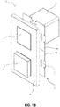
- FIGs. 1A and 1B schematically illustrate embodiments of a first implementation of a modular control device 10 according to the invention.
- the modular control device 10 is intended for being mounted on a wall or on a ceiling.
- the modular control device 10 may be a standalone device.
- standalone device is meant a device that is not part of a further system, such as for example a home automation system, and which can function fully independently.
- the modular control device 10 comprises a base module 1.
- the base module 1 may, for example, be a regular switch or a smart switch. According to a first embodiment of the first implementation, but not limited thereto, the base module 1 may be a switch.
- the switch 1 comprises a mounting box 2 for being placed in the wall or ceiling and housing the required electronics of the switch, smart switch or base module 1 in general. Also, in this mounting box 2 the device identification of the base module 1 is present. This couples the base module 1, and thus the modular control device 10, to a particular location.
- the modular control device 10 furthermore comprises at least one functional extension module 3.
- functional extension module 3 is meant a module for being added to the base module 1 to add a functionality to the control device 10.
- the functional extension module 3 can be any suitable functional extension module 3 as known by a person skilled in the art such as, for example but not limited to, a switch, a sensor module, a USB hub, a USB charger, a USB powerbank, a WiFi repeater, an intercom module, or the like.
- the senor module can comprise any suitable sensor device known by a person skilled in the art, such as for example but not limited to a VOC sensor, a CO2 sensor, a temperature sensor, an acoustic sensor, a relative humidity sensor or the like.
- the at least one functional extension module 3 is adapted for being removably connected to the base module 1 via a connection interface 4.
- This connection should in all cases both be mechanical and electrical, and allows current to be provided to the at least one functional extension module 3.
- the connection interface 4 is further adapted to allow data to be exchanged between the base module 1 and the at least one functional extension module 3.
- the connection interface may comprise an extension board 4.
- the extension board 4 provides place for the at least one functional extension module 3 and the base module 1.
- the extension board 4 may be fixed to the mounting box 2 in any suitable way as known by a person skilled in the art, such as e.g. by standard screws, or by a snap mechanism, or by a hook or clamp mechanism that is tightened with a screw onto the mounting box 2.
- the modular control device 10 furthermore comprises a cover plate 6 to finish it off.
- the cover plate 6 may be clicked onto the extension board 4 by means of any suitable click system.
- the click system may comprise snaps 7 on the extension board 4 that can be snapped into recesses on the back of the cover plate 6 (not shown).
- any other suitable fixing mechanism known by a person skilled in the art may be used.
- the cover plate 6 is removably connected to the extension board 4, so that it can be removed at any time, for example, when additional functional extension modules 3 have to be added and another cover plate 6 is required.
- the cover plate 6 may comprise as many openings 8 as required by the number of functional extension modules 3 present.
- the functional extension module 3 can be provided onto the cover plate 6 in different ways. According to embodiments of the invention, the functional extension module 3 may be removably connected by e.g. a snap mechanism, magnets, or any other suitable connection as known by a person skilled in the art, e.g. special connector ... Important to note is that the functional module 3 can be removably connected either to the cover plate 6 or directly onto the connection interface, in the example given to the extension board 4, and that the formed connection between the at least one functional extension module 3 and the base module 1 is both electrical and mechanical.
- a snap mechanism e.g. a snap mechanism, magnets, or any other suitable connection as known by a person skilled in the art, e.g. special connector ...
- the functional module 3 can be removably connected either to the cover plate 6 or directly onto the connection interface, in the example given to the extension board 4, and that the formed connection between the at least one functional extension module 3 and the base module 1 is both electrical and mechanical.
- the at least one functional extension module 3 can be connected to the extension board 4 by means of a snap connection.
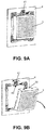
- Figs. 9A and 9B schematically illustrate part of the extension board 4 with a functional extension module 3.
- the at least one functional module 3 may comprise snap hooks 30 which grip behind an edge 40 of the extension board 4.
- a small lip 41 may be provided on the extension board. By pushing back the small lip 41, the extension board 4 is twisted backwards and the functional extension module 3 is thereby released.
- the extension board 4 may have two extension board parts 4a, 4b, one extension board part 4a for the base module 1 and one extension board part 4b for the functional extension module 3.
- the extension board 4 may have any suitable number of extension board parts 4a, 4b, 4c, ... as required for a particular user.
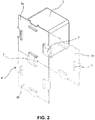
- An example is illustrated in Fig. 2 .
- the different parts 4a, 4b, 4c, ... can be mechanically connected, e.g. clicked together, in a way similar to pieces of a puzzle, as can be seen from the figures.
- the different extension board parts 4a, 4b, 4c, ... are further electrically connected. Therefore electrical connection 5 extend from one extension board part to another.
- Extension board parts 4a, 4b, 4c, ... can be connected together in both horizontal and vertical directions.
- the modular control device 10 furthermore comprises means for sending information to a remote device, such as e.g. a smart phone, a tablet, a computer or a gateway.
- a remote device such as e.g. a smart phone, a tablet, a computer or a gateway.
- the functional extension module 3 is a temperature or humidity sensor
- the sensed value may be sent to, for example, a smart phone so that a user can see if, e.g. air conditioning should be activated.
- these sensed values may be sent to a remote gateway, which then can activate the air conditioning so as to optimise the values of temperature and/or humidity. So, in general, information can be sent to a remote device so as to allow a user or an electric or electronic device to take action.
- the means for sending information may be further adapted to directly send information to an electric or electronic device, such as a lighting device, blinds, an HVAC system or the like, so as to activate and/or control these electric or electronic devices.
- an electric or electronic device such as a lighting device, blinds, an HVAC system or the like
- a modular control device 10 according to the first implementation can be provided in existing homes.
- a regular switch can be replaced by a modular control device 10 according to embodiments of the first implementation of the invention.
- an existing light switch or smart switch can be extended with additional functionalities by means of adding functional extension modules 3.
- the existing internal electronics should be replaced once by suitable electronics. This may preferably be done by an installer.
- the new electronics then allow to add the extension board for providing current to the functional extension module 3 and for allowing data exchange between the base module 1 and the functional extension module 3.
- the device identification is, as already mentioned above, is located in the mounting box 2 of the base module 1, once this base module 1 is installed, the location of the modular control device 10 is fixed.
- a functional extension module 3 is added to the base module 1, this functional extension module 3 is automatically linked to that specific location of the modular control device, because of the connection interface 4 that allows current and data to be exchanged between the base module 1 and the at least one functional extension module 4.
- An advantage of a modular control device 10 according to the first implementation is that functional extension module 3 can easily be fixed to and removed from the base module 1 over and over again. This makes it very easy to remove a functional extension module 3 when it doesn't work anymore or whenever a new functionality is required.
- the functional extension modules 3 are interchangeable between base modules 1 located in different rooms or at different locations within a room. In other words, each room or each location within a room has to be provided with a base module 1.
- functional extension modules 3 can be changed from one base module 1 to the other, depending on the needs of a user. Because the device identification of the base module 1 is located in the mounting box 2 of the base module 1, whenever a new functional extension module 3 is fixed to the base module 1 at whatever location, that new functional extension module 3 is automatically added to that location.
- Figs. 3 to 7 schematically illustrate embodiments of a second implementation of a modular control device 10 according to the invention.
- the modular control device 10 according to these embodiments is preferably intended for being mounted on a wall.
- the modular control device 10 may be part of a home automation system.
- the modular control device 10 comprises a base module 1, which may, for example, comprise a home automation system interface 1 such as e.g. a display or the like.
- the base module 1 comprises a mounting box 2 for mounting in the wall and comprising electronics for driving the modular control device 10. Similar as for the embodiments described above, the device identification is present in the mounting box 2 of the base module 1.
- the modular control device 10 also comprises at least one functional extension module 3.
- functional extension module 3 is meant a module for being added to the base module 1 to add a functionality to the control device 10.
- the at least one functional extension module 3 can be any suitable functional extension module 3 as known by a person skilled in the art such as, for example but not limited to, a sensor module, a USB hub, a USB charger, a USB powerbank, a WiFi repeater, an intercom module, a babyphone module or the like.
- the senor module can comprise any suitable sensor device known by a person skilled in the art, such as for example but not limited to a VOC sensor, a CO2 sensor, a temperature sensor, an acoustic sensor, a relative humidity sensor or the like.
- the modular control device 10 comprises a base module 1, in the example given a display 1, and at least one functional extension module 3.
- the display 1 may comprise a mounting box 2 for being placed in the wall and for housing the required electronics of the display or the home automation system interface 1 in general.
- the display 1 may comprise a recess (not shown in Figs. 4A to 4C ) and the functional extension module 3 may comprise a protrusion 11 that fits into the recess of the display 1 for removably fixing the functional extension module 3 to the base module 1.
- the at least one functional extension module 3 may preferably but not necessarily have a rectangular shape with a length equal to the width of the display 1.
- the shape of the modular control device 10 is a rectangle or a square. It has to be noted that, although in the example given in Fig. 3A to 3C , one functional extension module 3 is provided at a lower side of the display 1, this is not intended to limit the invention in any way. Functional extension modules can also be provided at all other sides of the display 1 and also a functional extension module 3 can be provided at more than one side of the display 1 a the same time.
- the modular control device 10 may comprise a base module 1 and a plurality of functional extension modules 3, in the example given four.
- the modular control device 10 may comprise a base module 1 and a plurality of functional extension modules 3, in the example given four.
- Fig. 5 there are three functional extension modules 3a, 3b, 3c that are directly connected or fixed to the base module 1 via protrusions 11 on the functional extension modules 3a, 3b, 3c. and recesses 12 in the bases module 1.
- Another functional extension module 3d may indirectly be connected to the base module 1, via connection to another functional extension module 3c. This increases the number of functional extension modules 3 that can be added to one base module 1.
- functional extension module 3c may additionally comprise a recess 13 for receiving the protrusion 11 of functional extension module 3d.
- a further embodiment is illustrated, in which the functional extension modules 3 have the shape of blocks, which have a plurality of small protrusions 11 that fit into small recesses 12 in the base module 1.
- dummy or filler pieces 14 may be provided such that the modular control device 10 has a nice rectangular or square shape in case there are not enough functional extension modules 3 fixed to the base module 1 to obtain such nice rectangular or square shape.
- the shape and size of the protrusions 11 and the recesses 12 can differ from embodiment to embodiment.
- This size and shape can, according to embodiments of the invention, depend on the kind of functional extension device but the protrusions 11 and recesses 12 can have any suitable shape and size.
- the protrusions and recesses should be such that they provide both a mechanical and an electrical connection between the at least one functional extension module 3 and the base module 1.
- the base module 1 may be configured to have a front side 1a and a back side 1b in between which the connection interface 4 is formed by kind of a connector block 1c that is part of the base module 1.
- the connector block 1c may have any suitable shape but has at least one protrusion 11 which are hidden in the base module 1.
- the at least one functional extension module 3 may then comprise a recess 13 for fitting the protrusion 11 on the connector block 1c in the base module 1.
- the hidden protrusions 11 may be such that, when the functional extension module(s) 3 is/are removably connected to the base module 1, the functional extension module(s) 3 is/are at least partially sunk in the base module 1.
- the at least one functional extension module 3 may be fully hidden in the base module 1.
- all functional extension modules 3 are provided such that they are fully hidden in the base module 1.
- at least part of the functional extension module 3 may come out of the base module 1 so as to ease cooling of the components or to make access to the functional extension module 3 possible.
- a breadboard 16 may be formed onto the base module 1 onto which the functional extension modules 3 can be removably connected. Therefore, the functional extension modules 3 may be provided with protrusions (not shown in the figure) for fitting into the small recesses 12 provided in the breadboard 16.
- Base module functionalities can be present at e.g. the lower part of the breadboard 16. This may, for example, be physical buttons of, for example, a light switch.
- Fig. 8 illustrates a further embodiment that can be used in the first implementation as well as in the second implementation described above.
- the connection interface 4 may be formed by a USB port on the base module 1.
- the functional extension module 3 then comprises a USB socket to be able to connect to the USB port 4 on the base module 1.
- information collected from the functional extension modules is sent to the electric or electronic device, such as lighting means, blinds, an alarm system, a HVAC system, or the like.
- Information can further be sent to a remote device such as, for example, a computer, a mobile phone, a display, a gateway of a home automation system or the like.
- Modular control devices 10 are preferably, but not limited to, used in new built houses.
- the user makes the choice to provide base modules 1 throughout the house. Whenever, at any time, the user wants to add functionalities, this can be done by simply connecting the required functional extension modules 3 to the base module 1.
- the connection with the electronics of the base module 1 through the connection interface 4 provides current to the functional extension module 3 and allows communicating with the home automation system (e.g. central control of data, output for example via an app on a smartphone or tablet).
- the home automation system e.g. central control of data, output for example via an app on a smartphone or tablet.
- one or more functional extension modules 3 can be removed from the base module 1 and can be fixed to another base module 1 in another room or at another location in the same room.
- Fixing and removing a functional extension module is very easy, and can be done fast, e.g. when the functional extension module 3 doesn't work anymore or whenever a new functionality is required.
- the functional extension modules are interchangeable between base modules located in different rooms or at different locations within a room. In other words, each room or each location within a room has to be provided with a base module. And from then on, functional extension modules can be changed from one base module to the other, depending on the needs of a user.
- any suitable number of functional extension modules 3 can be fixed to the base module 1 as required by a user.
- the functional extension modules 3 provided to the base module 1 can all be same functional extension modules 3 or can all be different functional extension modules 3. Any mix of same and different functional extension modules 3 is also possible.
- the modular control device 10 furthermore comprises means for sending information to a remote device, such as e.g. a smart phone, a tablet, a computer or a gateway.
- a remote device such as e.g. a smart phone, a tablet, a computer or a gateway.
- the functional extension module 3 is a temperature or humidity sensor
- the sensed value may be sent to, for example, a smart phone so that a user can see if, e.g. air conditioning should be activated.
- these sensed values may be sent to a remote gateway, which then can activate the air conditioning so as to optimise the values of temperature and/or humidity. So, in general, information can be sent to a remote device so as to allow a user or an electric or electronic device to take action.
- the means for sending information may be further adapted to directly send information to an electric or electronic device, such as a lighting device, blinds, an HVAC system or the like, so as to activate and/or control these electric or electronic devices.
- an electric or electronic device such as a lighting device, blinds, an HVAC system or the like
- a big advantage of a modular control device 10 according to embodiments of the invention is that a user can start with a simple base module 1 and can add, interchange, remove, re-add, ... functional extension modules 3 at any time and whenever required. This means that a user can start with a rather cheap system and can extend that system at its own tempo. It is further also possible to use temporary connected functional modules, such as e.g. power banks. They can be removed when needed and be fixed to the base module 1 again after use.
Landscapes
- Engineering & Computer Science (AREA)
- Automation & Control Theory (AREA)
- Computer Networks & Wireless Communication (AREA)
- Signal Processing (AREA)
- Architecture (AREA)
- Civil Engineering (AREA)
- Structural Engineering (AREA)
- Selective Calling Equipment (AREA)
Abstract
Description
- The present invention relates to control devices such as e.g. regular light switches, smart switches or home control interfaces. More particularly, the present invention relates to a modular control device comprising a base module to which easily functionality can be added by means of easily fixable, removable, interchangeable and re-fixable functional extension modules, lij
- Sensor are devices or systems whose purpose is to detect events or changes in their environment and send the information to a remote device, such as e.g. an electric or electronic device, but also a computer, a tablet, a smart phone, a gateway of a home automation system, or the like. A sensor is always used with other electronics, whether as simple as a light or as complex as a computer. The use of sensors in our homes is not new. Sensors have been used for some time now, e.g. in combination with alarm systems and/or for presence detection. However, nowadays sensors become more and more important to make our homes more smart. Many sensors for use in houses are available on the market, such as e.g. temperature sensors, acoustic sensors, VOC sensors, CO2 sensors, ...
- Sensors can be used as standalone devices but can also be incorporated in a home automation system. In a home automation system, the sensors are typically connected to a central hub or gateway to control electric or electronic devices, such as e.g. an HVAC system, blinds, lighting systems, ....
- A disadvantage of using sensors in home is that such sensors only have a limited life cycle. Further, sensor technology also rapidly evolves. Therefore, sensors need to be changed or replaced quite often. In current sensor systems, the whole system needs to be replaced, which is time consuming and expensive. Moreover, in a lot of cases a user can not do this him- or herself, but needs to ask for the help of an installer, which again increases the cost.
- It is an object of embodiments of the present invention to provide a modular control device for controlling electric or electronic devices, to which new functionalities can easily be added or removed.
- The above objective is accomplished by a device according to embodiments of the present invention.
- The present invention provides a modular control device. The modular control device comprises a base module adapted for being mounted on a wall or a ceiling and at least one functional extension module adapted for being removably connected to the base module via a connection interface. The connection interface allows current to be provided from the base module to the at least one functional extension module. The modular control device furthermore comprises means for sending information a remote device such as e.g. a mobile phone, a tablet or a computer.
- An advantage of a modular device according to embodiments of the invention is that it facilitates the replacement of one or more functional extension modules, whenever this would be necessary because of the need for new or other functional extension modules or because of the failure of the present functional modules. The replacement of the one or more functional extension modules can be done by the user him- or herself and does not need the interference of an installer. This makes it much cheaper than existing systems and devices, as only the relevant functional extension module needs to be replaced and not the complete system or device.
- According to embodiments of the invention, the base module may comprise a mounting box for being mounted in a wall. According to such embodiments, a device identification such as e.g. a MAC address of the base module is located in the mounting box.
- The modular control device may, according to embodiments of the invention, be adapted for controlling an electric or electronic device, such as e.g. a lighting device, an HVAC system, blinds, or the like. Therefore, the means for sending information of the modular control device may further be adapted to send information from the at least one functional extension module to the at least one electric or electronic device, i.e. for activating and/or controlling the at least one electric or electronic device.
- The connection interface may further be adapted for allowing data to be exchanged between the base module and the at least one functional extension module.
- According to particular embodiments, the modular control device may be a standalone device. According so such embodiments, the base module may, for example, be a regular light switch or a smart switch. The connection interface may comprises an extension board with at least two extension board parts. A modular control device according to
claim 7, the connection board comprising a plurality of extension board parts, wherein the plurality of extension board parts are mechanically and electrically interconnected. - The modular control device may further comprise a cover plate adapted for being removably connected to the extension board and for carrying the base module and the at least one functional extension module. The at least one functional extension module may be adapted for being removably connected to the cover plate by means of, for example, snaps, magnets, USB-C or the like.
- According to further embodiments, the modular control device may be part of a home automation system. According to such embodiments, the base module may comprise a home automation system interface such as e.g. a display, gateway, interconnection box or the like.
- According to embodiments of the invention, the home automation system interface may comprise at least one recess and the at least one functional extension module may comprise at least one protrusion mechanically fitting the at least one recess in the home automation system interface, the home automation system interface being adapted for exchanging power and data between the functional extension module and the base module.
- According to further embodiments, the home automation system interface may comprise at least one protrusion and the at least one functional extension module may comprise at least one recess for receiving the at least one protrusion of the home automation system interface, the home automation system interface being adapted for exchanging power and data between the functional extension module and the base module.
- According to still further embodiments, the at least one protrusion may be hidden in the home automation system interface such that, when removably fixing the at least one functional extension module to the home automation system interface, the at least one functional extension module is at least partially sunk in the home automation system interface.
- According to still further embodiments, a breadboard may be formed in at least part of the home automation interface, the breadboard comprising perforations in which small protrusions on the at least one functional extension module fit
- An advantage hereof is that the perforations in the breadboard can also serve as ventilation for cooling down the different components of the modular control device.
- According to embodiments of the invention, the connection interface may be a USB port.
- The at least one functional extension module may comprise at least one of a sensor module, a USB hub, a USB charger, a USB powerbank, a WiFi repeater, an intercom module , a babyphone module, or the like.
- It has to be noted that same reference signs in the different figures refer to same, similar or analogous elements.
-
Figs. 1A and1B schematically illustrate a modular control device according to an embodiment of a first implementation of the invention. -
Fig. 2 schematically illustrates an example of an extension board that can be used in a modular control device according to embodiments of the first implementation of the invention. -
Figs. 3A to 3C schematically illustrate a modular control device according to an embodiment of a second implementation of the invention. -
Fig. 4 schematically illustrate a modular control device according to an embodiment of a second implementation of the invention. -
Figs. 5A to 5D schematically illustrate a modular control device according to an embodiment of a second implementation of the invention. -
Figs. 6A to 6C schematically illustrate a modular control device according to an embodiment of a second implementation of the invention. -
Figs. 7A and 7B schematically illustrate a modular control device according to an embodiment of a second implementation of the invention. -
Figs. 8A and 8B schematically illustrate a modular control device according to an embodiment of a second implementation of the invention. -
Figs. 9A and 9B schematically illustrate part of the extension board with a functional extension module according to an embodiment of the invention. - In the description different embodiments will be used to describe the invention. Therefore reference will be made to different drawings. It has to be understood that these drawings are intended to be non-limiting, the invention is only limited by the claims. The drawings are thus for illustrative purposes, the size of some of the elements in the drawings may be exaggerated for clarity purposes.
- The term "comprising" is not to be interpreted as limiting the invention in any way. The term "comprising", used in the claims, is not intended to be restricted to what means is described thereafter; it does not exclude other elements, parts or steps.
- The term "connected" as used in the claims and in the description has not to be interpreted as being restricted to direct connections, unless otherwise specified. Thus, part A being connected to part B is not limited to part A being in direct contact to part B, but also includes indirect contact between part A and part B, in other words also includes the case where intermediate parts are present in between part A and part B.
- Not all embodiments of the invention comprise all features of the invention. In the following description and claims, any of the claimed embodiments can be used in any combination.
- The present invention provides a modular control device a base module adapted for being mounted on a wall or a ceiling, and at least one functional extension module adapted for being removably connected to the base module via a connection interface, the connection interface allowing current to be provided from the base module to the at least one functional extension module. The modular control device furthermore comprises means for sending information to a remote device, such as e.g. a mobile phone, a tablet or a computer. With functional extension module is meant a module for being added to the base module to add a functionality to the control device.
- An advantage of a modular control device according to embodiments of the invention is that it facilitates the replacement of one or more functional extension modules, whenever this would be necessary because of the need for new or other functional extension modules or because of the failure of the present functional modules. The replacement of the one or more functional extension modules can be done by the user him- or herself and does not need the interference of an installer. Further, the at least one functional extension module is not integrated in the modular control device, but remains a module separated from the control device. The at least one functional extension module is watertight, and can function on its own. Because of that, replacing one or more functional extension modules can be done by simply removing the current functional extension module and providing the new functional extension module. Power supply to the modular control device does not have to be interrupted for the interchange, removal or addition of a functional extension module, or in other words, the modular control device is such that the at least one functional extension module is hot-pluggable. Further, no other parts of the modular control devices have to be removed when replacing, adding or removing a functional extension module.
- The fact that the functional extension modules can easily be interchanged, removed or added, makes a modular control device according to embodiments of the invention much cheaper than existing systems and devices, as only the relevant functional extension module needs to be replaced and not the complete system or device.
- The present invention will hereinafter be described by means of different embodiments. It has to be understood that these embodiments are only for the ease of understanding the invention and are not intended to limit the invention in any way.
-
Figs. 1A and1B schematically illustrate embodiments of a first implementation of amodular control device 10 according to the invention. Themodular control device 10 is intended for being mounted on a wall or on a ceiling. - According to this first implementation, the
modular control device 10 may be a standalone device. With standalone device is meant a device that is not part of a further system, such as for example a home automation system, and which can function fully independently. - The
modular control device 10 comprises abase module 1. Thebase module 1 may, for example, be a regular switch or a smart switch. According to a first embodiment of the first implementation, but not limited thereto, thebase module 1 may be a switch. Theswitch 1 comprises a mountingbox 2 for being placed in the wall or ceiling and housing the required electronics of the switch, smart switch orbase module 1 in general. Also, in thismounting box 2 the device identification of thebase module 1 is present. This couples thebase module 1, and thus themodular control device 10, to a particular location. - The
modular control device 10 furthermore comprises at least onefunctional extension module 3. Withfunctional extension module 3 is meant a module for being added to thebase module 1 to add a functionality to thecontrol device 10. Thefunctional extension module 3 can be any suitablefunctional extension module 3 as known by a person skilled in the art such as, for example but not limited to, a switch, a sensor module, a USB hub, a USB charger, a USB powerbank, a WiFi repeater, an intercom module, or the like. In case of a sensor module, the senor module can comprise any suitable sensor device known by a person skilled in the art, such as for example but not limited to a VOC sensor, a CO2 sensor, a temperature sensor, an acoustic sensor, a relative humidity sensor or the like. - The at least one
functional extension module 3 is adapted for being removably connected to thebase module 1 via aconnection interface 4. This connection should in all cases both be mechanical and electrical, and allows current to be provided to the at least onefunctional extension module 3. In particular cases, theconnection interface 4 is further adapted to allow data to be exchanged between thebase module 1 and the at least onefunctional extension module 3. In the example given, the connection interface may comprise anextension board 4. Further, theextension board 4 provides place for the at least onefunctional extension module 3 and thebase module 1. Theextension board 4 may be fixed to the mountingbox 2 in any suitable way as known by a person skilled in the art, such as e.g. by standard screws, or by a snap mechanism, or by a hook or clamp mechanism that is tightened with a screw onto the mountingbox 2. - The
modular control device 10 furthermore comprises acover plate 6 to finish it off. Thecover plate 6 may be clicked onto theextension board 4 by means of any suitable click system. For example, the click system may comprisesnaps 7 on theextension board 4 that can be snapped into recesses on the back of the cover plate 6 (not shown). However, any other suitable fixing mechanism known by a person skilled in the art may be used. Important is that thecover plate 6 is removably connected to theextension board 4, so that it can be removed at any time, for example, when additionalfunctional extension modules 3 have to be added and anothercover plate 6 is required. Thecover plate 6 may comprise asmany openings 8 as required by the number offunctional extension modules 3 present. - The
functional extension module 3 can be provided onto thecover plate 6 in different ways. According to embodiments of the invention, thefunctional extension module 3 may be removably connected by e.g. a snap mechanism, magnets, or any other suitable connection as known by a person skilled in the art, e.g. special connector ... Important to note is that thefunctional module 3 can be removably connected either to thecover plate 6 or directly onto the connection interface, in the example given to theextension board 4, and that the formed connection between the at least onefunctional extension module 3 and thebase module 1 is both electrical and mechanical. - For example, the at least one
functional extension module 3 can be connected to theextension board 4 by means of a snap connection. This is illustrated inFigs. 9A and 9B , which schematically illustrate part of theextension board 4 with afunctional extension module 3. Therefore, the at least onefunctional module 3 may comprise snap hooks 30 which grip behind anedge 40 of theextension board 4. Asmall lip 41 may be provided on the extension board. By pushing back thesmall lip 41, theextension board 4 is twisted backwards and thefunctional extension module 3 is thereby released. - In its most simple shape, the
extension board 4 may have twoextension board parts extension board part 4a for thebase module 1 and oneextension board part 4b for thefunctional extension module 3. However, according to embodiments of the invention, theextension board 4 may have any suitable number ofextension board parts Fig. 2 . Thedifferent parts extension board parts electrical connection 5 extend from one extension board part to another.Extension board parts - The
modular control device 10 furthermore comprises means for sending information to a remote device, such as e.g. a smart phone, a tablet, a computer or a gateway. For example, when thefunctional extension module 3 is a temperature or humidity sensor, the sensed value may be sent to, for example, a smart phone so that a user can see if, e.g. air conditioning should be activated. Still further, these sensed values may be sent to a remote gateway, which then can activate the air conditioning so as to optimise the values of temperature and/or humidity. So, in general, information can be sent to a remote device so as to allow a user or an electric or electronic device to take action. - According to still further embodiments, the means for sending information may be further adapted to directly send information to an electric or electronic device, such as a lighting device, blinds, an HVAC system or the like, so as to activate and/or control these electric or electronic devices.
- A
modular control device 10 according to the first implementation can be provided in existing homes. In such cases, a regular switch can be replaced by amodular control device 10 according to embodiments of the first implementation of the invention. Or in other words, an existing light switch or smart switch can be extended with additional functionalities by means of addingfunctional extension modules 3. To make the existing switch or smart switch extendable, the existing internal electronics should be replaced once by suitable electronics. This may preferably be done by an installer. The new electronics then allow to add the extension board for providing current to thefunctional extension module 3 and for allowing data exchange between thebase module 1 and thefunctional extension module 3. As the device identification is, as already mentioned above, is located in themounting box 2 of thebase module 1, once thisbase module 1 is installed, the location of themodular control device 10 is fixed. That means that, whenever afunctional extension module 3 is added to thebase module 1, thisfunctional extension module 3 is automatically linked to that specific location of the modular control device, because of theconnection interface 4 that allows current and data to be exchanged between thebase module 1 and the at least onefunctional extension module 4. An advantage of amodular control device 10 according to the first implementation is thatfunctional extension module 3 can easily be fixed to and removed from thebase module 1 over and over again. This makes it very easy to remove afunctional extension module 3 when it doesn't work anymore or whenever a new functionality is required. Moreover, thefunctional extension modules 3 are interchangeable betweenbase modules 1 located in different rooms or at different locations within a room. In other words, each room or each location within a room has to be provided with abase module 1. And from then on,functional extension modules 3 can be changed from onebase module 1 to the other, depending on the needs of a user. Because the device identification of thebase module 1 is located in themounting box 2 of thebase module 1, whenever a newfunctional extension module 3 is fixed to thebase module 1 at whatever location, that newfunctional extension module 3 is automatically added to that location. - Further, whenever
new extension modules 3 with new functionalities become available on the market, only such newfunctional extension module 3 has to be bought and it can directly be used with thepresent base modules 1 in the house. - Because no electronics have to be touched, as adding a new
functional extension module 3 to abase module 1 only requires fixing, e.g. clicking, the newfunctional extension module 3 to thebase module 1, also no intervening of an installer is required and this can all be done by the user him- or herself. -
Figs. 3 to 7 schematically illustrate embodiments of a second implementation of amodular control device 10 according to the invention. Themodular control device 10 according to these embodiments is preferably intended for being mounted on a wall. According to this second implementation, themodular control device 10 may be part of a home automation system. - The
modular control device 10 comprises abase module 1, which may, for example, comprise a homeautomation system interface 1 such as e.g. a display or the like. Thebase module 1 comprises a mountingbox 2 for mounting in the wall and comprising electronics for driving themodular control device 10. Similar as for the embodiments described above, the device identification is present in themounting box 2 of thebase module 1. - Further, the
modular control device 10 also comprises at least onefunctional extension module 3. Withfunctional extension module 3 is meant a module for being added to thebase module 1 to add a functionality to thecontrol device 10. The at least onefunctional extension module 3 can be any suitablefunctional extension module 3 as known by a person skilled in the art such as, for example but not limited to, a sensor module, a USB hub, a USB charger, a USB powerbank, a WiFi repeater, an intercom module, a babyphone module or the like. In case of a sensor module, the senor module can comprise any suitable sensor device known by a person skilled in the art, such as for example but not limited to a VOC sensor, a CO2 sensor, a temperature sensor, an acoustic sensor, a relative humidity sensor or the like. - Hereinafter, different embodiments of the second implementation will be discussed.
-
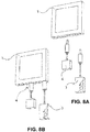
Figs. 3A to 3C schematically illustrate a first embodiment of the second implementation. Themodular control device 10 comprises abase module 1, in the example given adisplay 1, and at least onefunctional extension module 3. Thedisplay 1 may comprise amounting box 2 for being placed in the wall and for housing the required electronics of the display or the homeautomation system interface 1 in general. Thedisplay 1 may comprise a recess (not shown inFigs. 4A to 4C ) and thefunctional extension module 3 may comprise aprotrusion 11 that fits into the recess of thedisplay 1 for removably fixing thefunctional extension module 3 to thebase module 1. For aesthetical reasons, the at least onefunctional extension module 3 may preferably but not necessarily have a rectangular shape with a length equal to the width of thedisplay 1. In that way, when thefunctional extension module 3 is fixed onto thedisplay 1, the shape of themodular control device 10 is a rectangle or a square. It has to be noted that, although in the example given inFig. 3A to 3C , onefunctional extension module 3 is provided at a lower side of thedisplay 1, this is not intended to limit the invention in any way. Functional extension modules can also be provided at all other sides of thedisplay 1 and also afunctional extension module 3 can be provided at more than one side of the display 1 a the same time. - According to a further embodiment of the second implementation, which is illustrated in
Fig. 4 , themodular control device 10 may comprise abase module 1 and a plurality offunctional extension modules 3, in the example given four. As can be seen inFig. 5 there are threefunctional extension modules 3a, 3b, 3c that are directly connected or fixed to thebase module 1 viaprotrusions 11 on thefunctional extension modules 3a, 3b, 3c. and recesses 12 in thebases module 1. Anotherfunctional extension module 3d may indirectly be connected to thebase module 1, via connection to another functional extension module 3c. This increases the number offunctional extension modules 3 that can be added to onebase module 1. For the purpose of fixing the fourthfunctional extension module 3d, functional extension module 3c may additionally comprise arecess 13 for receiving theprotrusion 11 offunctional extension module 3d. - In
Fig. 5A to 5D , a further embodiment is illustrated, in which thefunctional extension modules 3 have the shape of blocks, which have a plurality ofsmall protrusions 11 that fit intosmall recesses 12 in thebase module 1. For aesthetic reasons, dummy orfiller pieces 14 may be provided such that themodular control device 10 has a nice rectangular or square shape in case there are not enoughfunctional extension modules 3 fixed to thebase module 1 to obtain such nice rectangular or square shape. - As can be seen from
Figs. 4A to 4C ,Fig. 5 andFig. 6 the shape and size of theprotrusions 11 and therecesses 12 can differ from embodiment to embodiment. This size and shape can, according to embodiments of the invention, depend on the kind of functional extension device but theprotrusions 11 and recesses 12 can have any suitable shape and size. However, according to the invention, only one requirement has to be met and that is that the protrusions and recesses should be such that they provide both a mechanical and an electrical connection between the at least onefunctional extension module 3 and thebase module 1. - A further embodiment of the second implementation is illustrated in
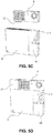
Fig. 6A to 6C . According to these embodiments, thebase module 1 may be configured to have a front side 1a and aback side 1b in between which theconnection interface 4 is formed by kind of a connector block 1c that is part of thebase module 1. The connector block 1c may have any suitable shape but has at least oneprotrusion 11 which are hidden in thebase module 1. The at least onefunctional extension module 3 may then comprise arecess 13 for fitting theprotrusion 11 on the connector block 1c in thebase module 1. The hiddenprotrusions 11 may be such that, when the functional extension module(s) 3 is/are removably connected to thebase module 1, the functional extension module(s) 3 is/are at least partially sunk in thebase module 1. According to embodiments of the invention, the at least onefunctional extension module 3 may be fully hidden in thebase module 1. Preferably, allfunctional extension modules 3 are provided such that they are fully hidden in thebase module 1. However, in some cases and depending on the type offunctional extension modules 3 used, e.g. when more ventilation is required because thefunctional extension module 3 comprises components that heat up during use, or whenever access to afunctional extension module 3 is required, at least part of thefunctional extension module 3 may come out of thebase module 1 so as to ease cooling of the components or to make access to thefunctional extension module 3 possible. - Still another embodiment of the second implementation is illustrated in
Fig. 7A and 7B . According to this embodiment, abreadboard 16 may be formed onto thebase module 1 onto which thefunctional extension modules 3 can be removably connected. Therefore, thefunctional extension modules 3 may be provided with protrusions (not shown in the figure) for fitting into thesmall recesses 12 provided in thebreadboard 16. Base module functionalities can be present at e.g. the lower part of thebreadboard 16. This may, for example, be physical buttons of, for example, a light switch. -
Fig. 8 illustrates a further embodiment that can be used in the first implementation as well as in the second implementation described above. According to this embodiment, theconnection interface 4 may be formed by a USB port on thebase module 1. Thefunctional extension module 3 then comprises a USB socket to be able to connect to theUSB port 4 on thebase module 1. In all of the above described embodiments, information collected from the functional extension modules is sent to the electric or electronic device, such as lighting means, blinds, an alarm system, a HVAC system, or the like. Information can further be sent to a remote device such as, for example, a computer, a mobile phone, a display, a gateway of a home automation system or the like. -
Modular control devices 10 according embodiments of the second implementation are preferably, but not limited to, used in new built houses. The user makes the choice to providebase modules 1 throughout the house. Whenever, at any time, the user wants to add functionalities, this can be done by simply connecting the requiredfunctional extension modules 3 to thebase module 1. The connection with the electronics of thebase module 1 through theconnection interface 4 provides current to thefunctional extension module 3 and allows communicating with the home automation system (e.g. central control of data, output for example via an app on a smartphone or tablet). After first installation, whenever required, one or morefunctional extension modules 3 can be removed from thebase module 1 and can be fixed to anotherbase module 1 in another room or at another location in the same room. Fixing and removing a functional extension module is very easy, and can be done fast, e.g. when thefunctional extension module 3 doesn't work anymore or whenever a new functionality is required. Moreover, the functional extension modules are interchangeable between base modules located in different rooms or at different locations within a room. In other words, each room or each location within a room has to be provided with a base module. And from then on, functional extension modules can be changed from one base module to the other, depending on the needs of a user. - Further, whenever new extension modules with new functionalities become available on the market, only such new functional extension module has to be bought and it can directly be used with the present base modules in the house.
- According to all embodiments of the invention described above, any suitable number of
functional extension modules 3 can be fixed to thebase module 1 as required by a user. According to embodiments of the invention, thefunctional extension modules 3 provided to thebase module 1 can all be samefunctional extension modules 3 or can all be differentfunctional extension modules 3. Any mix of same and differentfunctional extension modules 3 is also possible. - The
modular control device 10 furthermore comprises means for sending information to a remote device, such as e.g. a smart phone, a tablet, a computer or a gateway. For example, when thefunctional extension module 3 is a temperature or humidity sensor, the sensed value may be sent to, for example, a smart phone so that a user can see if, e.g. air conditioning should be activated. Still further, these sensed values may be sent to a remote gateway, which then can activate the air conditioning so as to optimise the values of temperature and/or humidity. So, in general, information can be sent to a remote device so as to allow a user or an electric or electronic device to take action. - According to still further embodiments, the means for sending information may be further adapted to directly send information to an electric or electronic device, such as a lighting device, blinds, an HVAC system or the like, so as to activate and/or control these electric or electronic devices.
- A big advantage of a
modular control device 10 according to embodiments of the invention is that a user can start with asimple base module 1 and can add, interchange, remove, re-add, ...functional extension modules 3 at any time and whenever required. This means that a user can start with a rather cheap system and can extend that system at its own tempo. It is further also possible to use temporary connected functional modules, such as e.g. power banks. They can be removed when needed and be fixed to thebase module 1 again after use.
Claims (15)
- A modular control device (10) comprising:- a base module (1) adapted for being mounted on a wall or a ceiling,- at least one functional extension module (3) adapted for being removably connected to the base module (1) via a connection interface (4), the connection interface (4) allowing current to be provided from the base module (1) to the at least one functional extension module (3), and- means for sending information to a remote device.
- A modular control device (10) according to claim 1, the base module (1) comprising a mounting box (2) for being mounted in a wall, wherein a device identification of the base module (1) is located in the mounting box (2).
- A modular control device (10) according to claim 1 or 2, wherein the means for sending information is further adapted to send information from the at least one functional extension module (3) to at least one electric or electronic device so as to activate and/or control the at least one electric or electronic device.
- A modular control device (10) according to any of the previous claims, wherein the connection interface (4) is further adapted for allowing data to be exchanged between the base module (1) and the at least one functional extension module (3).
- A modular control device (10) according to any of the previous claims, wherein the modular control device (10) is a standalone device.
- A modular control device (10) according to claim 5, wherein the connection interface (4) comprises an extension board with at least two extension board parts (4a, 4b, 4c).
- A modular control device (10) according to claim 6, the connection board (4) comprising a plurality of extension board parts (4a, 4b, 4c), wherein the plurality of extension board parts (4a, 4b, 4c) are mechanically and electrically interconnected.
- A modular control device (10) according to claim 6 or 7, further comprising a cover plate (6) adapted for being removably connected to the extension board (4) and for carrying the base module (1) and the at least one functional extension module (3).
- A modular control device (10) according to claim 8, wherein the at least one functional extension module (3) is adapted for being removably connected to the cover plate (6).
- A modular control device (10) according to any of claims 1 to 4, wherein the modular control device (10) is part of a home automation system.
- A modular control device (10) according to claim 10, wherein the base module (1) comprises a home automation system interface.
- A modular control device (10) according to claim 11, the home automation system interface (1) comprising at least one recess (12) and the at least one functional extension module (3) comprising at least one protrusion (11) mechanically fitting the at least one recess (13) in the home automation system interface (1)
- A modular control device (10) according to claim 11, the home automation system interface (1) comprising at least one protrusion (15) and the at least one functional extension module (3) comprising at least one recess (13) for receiving the at least one protrusion (15) of the home automation system interface (1).
- A modular control device (10) according to claim 13, wherein the at least one protrusion (15) is hidden in the home automation system interface (1) such that, when removably fixing the at least one functional extension module (3) to the home automation system interface (1), the at least one functional extension module (3) is at least partially sunk in the home automation system interface (1).
- A modular control device (10) according to claim 11, wherein a breadboard (16) is formed in at least part of the home automation interface (1), the breadboard (16) comprising perforations in which small protrusions (11) on the at least one functional extension module (3) fit.
Applications Claiming Priority (1)
| Application Number | Priority Date | Filing Date | Title |
|---|---|---|---|
| BE20185531A BE1026486B1 (en) | 2018-07-24 | 2018-07-24 | Modular control device |
Publications (1)
| Publication Number | Publication Date |
|---|---|
| EP3599687A1 true EP3599687A1 (en) | 2020-01-29 |
Family
ID=63914723
Family Applications (1)
| Application Number | Title | Priority Date | Filing Date |
|---|---|---|---|
| EP19187969.1A Pending EP3599687A1 (en) | 2018-07-24 | 2019-07-24 | Modular control device |
Country Status (2)
| Country | Link |
|---|---|
| EP (1) | EP3599687A1 (en) |
| BE (1) | BE1026486B1 (en) |
Cited By (1)
| Publication number | Priority date | Publication date | Assignee | Title |
|---|---|---|---|---|
| GR1010443B (en) * | 2022-08-11 | 2023-04-07 | Codebender R&D Hellas Μονοπροσωπη Ι.Κ.Ε., | Potable self-secured power distributor for experimental electronic circuit arrangement devices |
Citations (7)
| Publication number | Priority date | Publication date | Assignee | Title |
|---|---|---|---|---|
| EP0344609A2 (en) * | 1988-06-01 | 1989-12-06 | Gebrüder Merten Gmbh & Co. Kg | Digital signal transmission system for domestic application |
| EP0452658A1 (en) * | 1990-04-03 | 1991-10-23 | Gebrüder Merten Gmbh & Co. Kg | Connection unit for domestic applications |
| DE19943570A1 (en) * | 1998-09-14 | 2000-04-06 | Grothe & Soehne Gmbh & Co Kg A | Communication station at house, or flat door with one or more bell pushbuttons as functional module connectable to other such modules |
| EP1993180A2 (en) * | 2007-05-12 | 2008-11-19 | Abb Ag | Sensor unit for mounting in an installation box |
| EP2043123A2 (en) * | 2007-09-25 | 2009-04-01 | Albrecht Jung GmbH & Co. KG | Electric/electronic installation device |
| EP2645501A1 (en) * | 2012-03-28 | 2013-10-02 | Gira Giersiepen GmbH & Co. Kg | System module for electroinstallation technology for buildings and door communication technology |
| US9940884B1 (en) * | 2012-08-31 | 2018-04-10 | Sergey Musolin | Automated dimmer wall switch with a color multi-touch LCD/LED display |
-
2018
- 2018-07-24 BE BE20185531A patent/BE1026486B1/en active IP Right Grant
-
2019
- 2019-07-24 EP EP19187969.1A patent/EP3599687A1/en active Pending
Patent Citations (7)
| Publication number | Priority date | Publication date | Assignee | Title |
|---|---|---|---|---|
| EP0344609A2 (en) * | 1988-06-01 | 1989-12-06 | Gebrüder Merten Gmbh & Co. Kg | Digital signal transmission system for domestic application |
| EP0452658A1 (en) * | 1990-04-03 | 1991-10-23 | Gebrüder Merten Gmbh & Co. Kg | Connection unit for domestic applications |
| DE19943570A1 (en) * | 1998-09-14 | 2000-04-06 | Grothe & Soehne Gmbh & Co Kg A | Communication station at house, or flat door with one or more bell pushbuttons as functional module connectable to other such modules |
| EP1993180A2 (en) * | 2007-05-12 | 2008-11-19 | Abb Ag | Sensor unit for mounting in an installation box |
| EP2043123A2 (en) * | 2007-09-25 | 2009-04-01 | Albrecht Jung GmbH & Co. KG | Electric/electronic installation device |
| EP2645501A1 (en) * | 2012-03-28 | 2013-10-02 | Gira Giersiepen GmbH & Co. Kg | System module for electroinstallation technology for buildings and door communication technology |
| US9940884B1 (en) * | 2012-08-31 | 2018-04-10 | Sergey Musolin | Automated dimmer wall switch with a color multi-touch LCD/LED display |
Cited By (1)
| Publication number | Priority date | Publication date | Assignee | Title |
|---|---|---|---|---|
| GR1010443B (en) * | 2022-08-11 | 2023-04-07 | Codebender R&D Hellas Μονοπροσωπη Ι.Κ.Ε., | Potable self-secured power distributor for experimental electronic circuit arrangement devices |
Also Published As
| Publication number | Publication date |
|---|---|
| BE1026486A1 (en) | 2020-02-17 |
| BE1026486B1 (en) | 2020-02-25 |
Similar Documents
| Publication | Publication Date | Title |
|---|---|---|
| CN110741514B (en) | Modular intelligent quick-connect apparatus for electrical devices | |
| US20210372645A1 (en) | Multipurpose multifunction device | |
| US8742892B1 (en) | Method and apparatus for assigning and imprinting touch icons of a touch pad | |
| CN107223218B (en) | Power control system for retrofitting into a building | |
| EP2751874B1 (en) | Electric box safety redesign | |
| US20160191268A1 (en) | Interchangeable Modular Home Automation System | |
| US20160156378A1 (en) | Electronic Smart Device Holder | |
| CN106132124A (en) | The Smart Home box of split-type structural | |
| EP3599687A1 (en) | Modular control device | |
| EP3258326B1 (en) | Automated control system for homes | |
| EP3565127A1 (en) | Integration device for integrating function modules | |
| US20230419672A1 (en) | Configurable modular devices and other systems and methods | |
| CA2902518A1 (en) | Integrated cover plate and sensor system | |
| TWM542228U (en) | Touch switch capable of increasing functions | |
| US20210271273A1 (en) | Thermostat | |
| JP2021052290A (en) | Radio communication apparatus, and wiring equipment system | |
| EP3610610B1 (en) | Modular multifunctional home automation device adapted to be inserted as an element in an electrical box | |
| KR101102580B1 (en) | Device for controlling outlet and method for the same | |
| WO2021059711A1 (en) | Wireless communication device, network system and network provision method | |
| JP2015204476A (en) | House information panel, power supply device and interphone device for apartment house | |
| CN116529597A (en) | System and method for configuring modular air quality sensing capability | |
| JP2021106121A (en) | Usb receptacle | |
| WO2022117511A1 (en) | Systems and methods for configuring modular air quality sensing capabilities | |
| JP2015097354A (en) | Network system |
Legal Events
| Date | Code | Title | Description |
|---|---|---|---|
| PUAI | Public reference made under article 153(3) epc to a published international application that has entered the european phase |
Free format text: ORIGINAL CODE: 0009012 |
|
| STAA | Information on the status of an ep patent application or granted ep patent |
Free format text: STATUS: THE APPLICATION HAS BEEN PUBLISHED |
|
| AK | Designated contracting states |
Kind code of ref document: A1 Designated state(s): AL AT BE BG CH CY CZ DE DK EE ES FI FR GB GR HR HU IE IS IT LI LT LU LV MC MK MT NL NO PL PT RO RS SE SI SK SM TR |
|
| AX | Request for extension of the european patent |
Extension state: BA ME |
|
| STAA | Information on the status of an ep patent application or granted ep patent |
Free format text: STATUS: REQUEST FOR EXAMINATION WAS MADE |
|
| 17P | Request for examination filed |
Effective date: 20200729 |
|
| RBV | Designated contracting states (corrected) |
Designated state(s): AL AT BE BG CH CY CZ DE DK EE ES FI FR GB GR HR HU IE IS IT LI LT LU LV MC MK MT NL NO PL PT RO RS SE SI SK SM TR |
|
| STAA | Information on the status of an ep patent application or granted ep patent |
Free format text: STATUS: EXAMINATION IS IN PROGRESS |
|
| 17Q | First examination report despatched |
Effective date: 20220223 |
|
| P01 | Opt-out of the competence of the unified patent court (upc) registered |
Effective date: 20230526 |
|
| GRAP | Despatch of communication of intention to grant a patent |
Free format text: ORIGINAL CODE: EPIDOSNIGR1 |
|
| STAA | Information on the status of an ep patent application or granted ep patent |
Free format text: STATUS: GRANT OF PATENT IS INTENDED |
|
| INTG | Intention to grant announced |
Effective date: 20240228 |