EP3598341B1 - Implementation of biometric authentication using a viewfinder - Google Patents
Implementation of biometric authentication using a viewfinder Download PDFInfo
- Publication number
- EP3598341B1 EP3598341B1 EP19194828.0A EP19194828A EP3598341B1 EP 3598341 B1 EP3598341 B1 EP 3598341B1 EP 19194828 A EP19194828 A EP 19194828A EP 3598341 B1 EP3598341 B1 EP 3598341B1
- Authority
- EP
- European Patent Office
- Prior art keywords
- user
- cameras
- view
- biometric
- field
- Prior art date
- Legal status (The legal status is an assumption and is not a legal conclusion. Google has not performed a legal analysis and makes no representation as to the accuracy of the status listed.)
- Active
Links
- 238000000034 method Methods 0.000 claims description 98
- 230000004044 response Effects 0.000 claims description 40
- 230000008569 process Effects 0.000 claims description 39
- 230000008859 change Effects 0.000 claims description 32
- 230000000977 initiatory effect Effects 0.000 claims description 9
- 230000001965 increasing effect Effects 0.000 claims description 5
- 230000001815 facial effect Effects 0.000 description 44
- 230000000007 visual effect Effects 0.000 description 28
- 230000004913 activation Effects 0.000 description 14
- 230000036961 partial effect Effects 0.000 description 8
- 238000006073 displacement reaction Methods 0.000 description 6
- 230000006870 function Effects 0.000 description 6
- 238000005259 measurement Methods 0.000 description 6
- 230000002411 adverse Effects 0.000 description 5
- 238000012790 confirmation Methods 0.000 description 5
- 230000007423 decrease Effects 0.000 description 5
- 238000004891 communication Methods 0.000 description 4
- 238000005516 engineering process Methods 0.000 description 4
- 238000012986 modification Methods 0.000 description 4
- 230000004048 modification Effects 0.000 description 4
- 230000035807 sensation Effects 0.000 description 4
- 230000021317 sensory perception Effects 0.000 description 4
- 230000001149 cognitive effect Effects 0.000 description 3
- 230000003111 delayed effect Effects 0.000 description 3
- 238000001514 detection method Methods 0.000 description 3
- 238000009432 framing Methods 0.000 description 3
- 230000002829 reductive effect Effects 0.000 description 3
- 230000007704 transition Effects 0.000 description 3
- 238000013459 approach Methods 0.000 description 2
- 230000008901 benefit Effects 0.000 description 2
- 230000000295 complement effect Effects 0.000 description 2
- 238000004590 computer program Methods 0.000 description 2
- 238000010586 diagram Methods 0.000 description 2
- 230000000694 effects Effects 0.000 description 2
- 230000000670 limiting effect Effects 0.000 description 2
- 238000005192 partition Methods 0.000 description 2
- 238000012546 transfer Methods 0.000 description 2
- 208000033748 Device issues Diseases 0.000 description 1
- 241001422033 Thestylus Species 0.000 description 1
- 230000001133 acceleration Effects 0.000 description 1
- 230000003213 activating effect Effects 0.000 description 1
- 238000004458 analytical method Methods 0.000 description 1
- 238000013475 authorization Methods 0.000 description 1
- 230000006399 behavior Effects 0.000 description 1
- 230000003247 decreasing effect Effects 0.000 description 1
- 230000001934 delay Effects 0.000 description 1
- 230000001419 dependent effect Effects 0.000 description 1
- 230000002708 enhancing effect Effects 0.000 description 1
- 238000011156 evaluation Methods 0.000 description 1
- 230000003993 interaction Effects 0.000 description 1
- 238000007726 management method Methods 0.000 description 1
- 230000003287 optical effect Effects 0.000 description 1
- 230000010355 oscillation Effects 0.000 description 1
- 230000008447 perception Effects 0.000 description 1
- 238000012545 processing Methods 0.000 description 1
- 230000009467 reduction Effects 0.000 description 1
- 230000003252 repetitive effect Effects 0.000 description 1
- 238000000926 separation method Methods 0.000 description 1
Images


Classifications
-
- G—PHYSICS
- G06—COMPUTING; CALCULATING OR COUNTING
- G06F—ELECTRIC DIGITAL DATA PROCESSING
- G06F21/00—Security arrangements for protecting computers, components thereof, programs or data against unauthorised activity
- G06F21/30—Authentication, i.e. establishing the identity or authorisation of security principals
- G06F21/31—User authentication
- G06F21/32—User authentication using biometric data, e.g. fingerprints, iris scans or voiceprints
-
- G—PHYSICS
- G06—COMPUTING; CALCULATING OR COUNTING
- G06V—IMAGE OR VIDEO RECOGNITION OR UNDERSTANDING
- G06V40/00—Recognition of biometric, human-related or animal-related patterns in image or video data
- G06V40/10—Human or animal bodies, e.g. vehicle occupants or pedestrians; Body parts, e.g. hands
- G06V40/12—Fingerprints or palmprints
-
- G—PHYSICS
- G06—COMPUTING; CALCULATING OR COUNTING
- G06F—ELECTRIC DIGITAL DATA PROCESSING
- G06F18/00—Pattern recognition
-
- G—PHYSICS
- G06—COMPUTING; CALCULATING OR COUNTING
- G06F—ELECTRIC DIGITAL DATA PROCESSING
- G06F21/00—Security arrangements for protecting computers, components thereof, programs or data against unauthorised activity
- G06F21/30—Authentication, i.e. establishing the identity or authorisation of security principals
- G06F21/45—Structures or tools for the administration of authentication
-
- G—PHYSICS
- G06—COMPUTING; CALCULATING OR COUNTING
- G06F—ELECTRIC DIGITAL DATA PROCESSING
- G06F3/00—Input arrangements for transferring data to be processed into a form capable of being handled by the computer; Output arrangements for transferring data from processing unit to output unit, e.g. interface arrangements
- G06F3/01—Input arrangements or combined input and output arrangements for interaction between user and computer
- G06F3/048—Interaction techniques based on graphical user interfaces [GUI]
- G06F3/0481—Interaction techniques based on graphical user interfaces [GUI] based on specific properties of the displayed interaction object or a metaphor-based environment, e.g. interaction with desktop elements like windows or icons, or assisted by a cursor's changing behaviour or appearance
-
- G—PHYSICS
- G06—COMPUTING; CALCULATING OR COUNTING
- G06F—ELECTRIC DIGITAL DATA PROCESSING
- G06F3/00—Input arrangements for transferring data to be processed into a form capable of being handled by the computer; Output arrangements for transferring data from processing unit to output unit, e.g. interface arrangements
- G06F3/01—Input arrangements or combined input and output arrangements for interaction between user and computer
- G06F3/048—Interaction techniques based on graphical user interfaces [GUI]
- G06F3/0487—Interaction techniques based on graphical user interfaces [GUI] using specific features provided by the input device, e.g. functions controlled by the rotation of a mouse with dual sensing arrangements, or of the nature of the input device, e.g. tap gestures based on pressure sensed by a digitiser
- G06F3/0488—Interaction techniques based on graphical user interfaces [GUI] using specific features provided by the input device, e.g. functions controlled by the rotation of a mouse with dual sensing arrangements, or of the nature of the input device, e.g. tap gestures based on pressure sensed by a digitiser using a touch-screen or digitiser, e.g. input of commands through traced gestures
-
- G—PHYSICS
- G06—COMPUTING; CALCULATING OR COUNTING
- G06F—ELECTRIC DIGITAL DATA PROCESSING
- G06F9/00—Arrangements for program control, e.g. control units
- G06F9/06—Arrangements for program control, e.g. control units using stored programs, i.e. using an internal store of processing equipment to receive or retain programs
- G06F9/44—Arrangements for executing specific programs
- G06F9/451—Execution arrangements for user interfaces
-
- G—PHYSICS
- G06—COMPUTING; CALCULATING OR COUNTING
- G06T—IMAGE DATA PROCESSING OR GENERATION, IN GENERAL
- G06T7/00—Image analysis
- G06T7/70—Determining position or orientation of objects or cameras
-
- G—PHYSICS
- G06—COMPUTING; CALCULATING OR COUNTING
- G06V—IMAGE OR VIDEO RECOGNITION OR UNDERSTANDING
- G06V10/00—Arrangements for image or video recognition or understanding
- G06V10/20—Image preprocessing
- G06V10/24—Aligning, centring, orientation detection or correction of the image
-
- G—PHYSICS
- G06—COMPUTING; CALCULATING OR COUNTING
- G06V—IMAGE OR VIDEO RECOGNITION OR UNDERSTANDING
- G06V10/00—Arrangements for image or video recognition or understanding
- G06V10/98—Detection or correction of errors, e.g. by rescanning the pattern or by human intervention; Evaluation of the quality of the acquired patterns
-
- G—PHYSICS
- G06—COMPUTING; CALCULATING OR COUNTING
- G06V—IMAGE OR VIDEO RECOGNITION OR UNDERSTANDING
- G06V40/00—Recognition of biometric, human-related or animal-related patterns in image or video data
- G06V40/10—Human or animal bodies, e.g. vehicle occupants or pedestrians; Body parts, e.g. hands
- G06V40/16—Human faces, e.g. facial parts, sketches or expressions
-
- G—PHYSICS
- G06—COMPUTING; CALCULATING OR COUNTING
- G06V—IMAGE OR VIDEO RECOGNITION OR UNDERSTANDING
- G06V40/00—Recognition of biometric, human-related or animal-related patterns in image or video data
- G06V40/10—Human or animal bodies, e.g. vehicle occupants or pedestrians; Body parts, e.g. hands
- G06V40/18—Eye characteristics, e.g. of the iris
-
- G—PHYSICS
- G06—COMPUTING; CALCULATING OR COUNTING
- G06V—IMAGE OR VIDEO RECOGNITION OR UNDERSTANDING
- G06V40/00—Recognition of biometric, human-related or animal-related patterns in image or video data
- G06V40/60—Static or dynamic means for assisting the user to position a body part for biometric acquisition
- G06V40/67—Static or dynamic means for assisting the user to position a body part for biometric acquisition by interactive indications to the user
-
- G—PHYSICS
- G06—COMPUTING; CALCULATING OR COUNTING
- G06V—IMAGE OR VIDEO RECOGNITION OR UNDERSTANDING
- G06V40/00—Recognition of biometric, human-related or animal-related patterns in image or video data
- G06V40/70—Multimodal biometrics, e.g. combining information from different biometric modalities
-
- H—ELECTRICITY
- H04—ELECTRIC COMMUNICATION TECHNIQUE
- H04L—TRANSMISSION OF DIGITAL INFORMATION, e.g. TELEGRAPHIC COMMUNICATION
- H04L63/00—Network architectures or network communication protocols for network security
- H04L63/08—Network architectures or network communication protocols for network security for authentication of entities
- H04L63/0861—Network architectures or network communication protocols for network security for authentication of entities using biometrical features, e.g. fingerprint, retina-scan
-
- H—ELECTRICITY
- H04—ELECTRIC COMMUNICATION TECHNIQUE
- H04L—TRANSMISSION OF DIGITAL INFORMATION, e.g. TELEGRAPHIC COMMUNICATION
- H04L9/00—Cryptographic mechanisms or cryptographic arrangements for secret or secure communications; Network security protocols
- H04L9/32—Cryptographic mechanisms or cryptographic arrangements for secret or secure communications; Network security protocols including means for verifying the identity or authority of a user of the system or for message authentication, e.g. authorization, entity authentication, data integrity or data verification, non-repudiation, key authentication or verification of credentials
- H04L9/3226—Cryptographic mechanisms or cryptographic arrangements for secret or secure communications; Network security protocols including means for verifying the identity or authority of a user of the system or for message authentication, e.g. authorization, entity authentication, data integrity or data verification, non-repudiation, key authentication or verification of credentials using a predetermined code, e.g. password, passphrase or PIN
- H04L9/3231—Biological data, e.g. fingerprint, voice or retina
-
- H—ELECTRICITY
- H04—ELECTRIC COMMUNICATION TECHNIQUE
- H04N—PICTORIAL COMMUNICATION, e.g. TELEVISION
- H04N23/00—Cameras or camera modules comprising electronic image sensors; Control thereof
- H04N23/60—Control of cameras or camera modules
- H04N23/61—Control of cameras or camera modules based on recognised objects
- H04N23/611—Control of cameras or camera modules based on recognised objects where the recognised objects include parts of the human body
-
- H—ELECTRICITY
- H04—ELECTRIC COMMUNICATION TECHNIQUE
- H04N—PICTORIAL COMMUNICATION, e.g. TELEVISION
- H04N23/00—Cameras or camera modules comprising electronic image sensors; Control thereof
- H04N23/60—Control of cameras or camera modules
- H04N23/63—Control of cameras or camera modules by using electronic viewfinders
- H04N23/631—Graphical user interfaces [GUI] specially adapted for controlling image capture or setting capture parameters
- H04N23/632—Graphical user interfaces [GUI] specially adapted for controlling image capture or setting capture parameters for displaying or modifying preview images prior to image capturing, e.g. variety of image resolutions or capturing parameters
-
- G—PHYSICS
- G06—COMPUTING; CALCULATING OR COUNTING
- G06T—IMAGE DATA PROCESSING OR GENERATION, IN GENERAL
- G06T2207/00—Indexing scheme for image analysis or image enhancement
- G06T2207/10—Image acquisition modality
- G06T2207/10016—Video; Image sequence
Definitions
- the present disclosure relates generally to biometric authentication, and more specifically to interfaces and techniques for enrollment and authentication of biometric features.
- Biometric authentication for instance of a face, iris, or fingerprint, using electronic devices is a convenient and efficient method of authenticating users of the electronic devices. Biometric authentication allows a device to quickly and easily verify the identity of any number of users.
- US 2013/336545 A1 discloses a mobile device able to capture a plurality of different biometric identifiers of a subject.
- US 9 716 825 B1 discloses a user interface for camera effects.
- an electronic device transitions between user interfaces for capturing photos based on data received from a first camera and a second camera.
- the electronic device provides enhanced zooming capabilities that result in visual pleasing results for a displayed digital viewfinder and for captured videos.
- the electronic device provides user interfaces for transitioning a digital viewfinder between a first camera with an applied digital zoom to a second camera with no digital zoom.
- the electronic device prepares to capture media at various magnification levels.
- US 8 254 647 B1 discloses techniques for assessing image quality of captured facial images.
- An example method includes capturing an image, generating a facial detection confidence score based in part on a likelihood that a representation of at least a portion of a face is included in the image, generating a facial landmark detection confidence score based at least in part on a likelihood that representations of facial landmarks are accurately identified in the image, and generating a geometric consistency score based at least in part on a difference between a point of intersection between a nose base and a line segment that passes through each eye and a midpoint of the line segment.
- Some techniques for implementing biometric authentication using electronic devices are generally cumbersome.
- some existing techniques such as those directed to facial recognition, require a user to almost perfectly align a biometric feature in a same manner during both enrollment and each iteration of authentication. Deviation from the alignment of the biometric feature often results in a false negative result.
- a user is, optionally, required to unnecessarily perform multiple iterations of biometric authentication, or is, optionally, discouraged from using the biometric authentication altogether.
- some existing techniques rely solely on a two-dimensional representation of a biometric feature.
- authentication of a user is, optionally, limited by virtue of a failure to analyze one or more three-dimensional characteristics of the biometric feature and also optionally requires a user to unnecessarily perform additional iterations of biometric authentication.
- existing techniques require more time than necessary, wasting both user time and device energy. This latter consideration is particularly significant in the operation of battery-operated devices.
- the present technique provides electronic devices with faster, more efficient methods and interfaces for implementing biometric authentication.
- Such methods and interfaces optionally complement or replace other methods for implementing biometric authentication.
- Such methods and interfaces reduce the cognitive burden on a user and produce a more efficient human-machine interface.
- Such methods and interfaces conserve power and increase the time between battery charges.
- Such methods and interfaces also reduce the number of unnecessary, extraneous, or repetitive input required at computing devices, such as smartphones and smartwatches.
- Executable instructions for performing these functions are, optionally, included in a non-transitory computer-readable storage medium or other computer program product configured for execution by one or more processors. Executable instructions for performing these functions are, optionally, included in a transitory computer-readable storage medium or other computer program product configured for execution by one or more processors.
- devices are provided with faster, more efficient methods and interfaces for implementing biometric authentication, thereby increasing the effectiveness, efficiency, and user satisfaction with such devices.
- Such methods and interfaces optionally complement or replace other methods for implementing biometric authentication.
- first means "first,” “second,” etc. to describe various elements, these elements should not be limited by the terms. These terms are only used to distinguish one element from another.
- a first touch could be termed a second touch, and, similarly, a second touch could be termed a first touch, without departing from the scope of the various described embodiments.
- the first touch and the second touch are both touches, but they are not the same touch.
- the device is a portable communications device, such as a mobile telephone, that also contains other functions, such as PDA and/or music player functions.
- portable multifunction devices include, without limitation, the iPhone ® , iPod Touch ® , and iPad ® devices from Apple Inc. of Cupertino, California.
- Other portable electronic devices such as laptops or tablet computers with touch-sensitive surfaces (e.g., touch screen displays and/or touchpads), are, optionally, used.
- the device is not a portable communications device, but is a desktop computer with a touch-sensitive surface (e.g., a touch screen display and/or a touchpad).
- an electronic device that includes a display and a touch-sensitive surface is described. It should be understood, however, that the electronic device optionally includes one or more other physical user-interface devices, such as a physical keyboard, a mouse, and/or a joystick.
- the device typically supports a variety of applications, such as one or more of the following: a drawing application, a presentation application, a word processing application, a website creation application, a disk authoring application, a spreadsheet application, a gaming application, a telephone application, a video conferencing application, an e-mail application, an instant messaging application, a workout support application, a photo management application, a digital camera application, a digital video camera application, a web browsing application, a digital music player application, and/or a digital video player application.
- applications such as one or more of the following: a drawing application, a presentation application, a word processing application, a website creation application, a disk authoring application, a spreadsheet application, a gaming application, a telephone application, a video conferencing application, an e-mail application, an instant messaging application, a workout support application, a photo management application, a digital camera application, a digital video camera application, a web browsing application, a digital music player application, and/or a digital video player application.
- the various applications that are executed on the device optionally use at least one common physical user-interface device, such as the touch-sensitive surface.
- One or more functions of the touch-sensitive surface as well as corresponding information displayed on the device are, optionally, adjusted and/or varied from one application to the next and/or within a respective application.
- a common physical architecture (such as the touch-sensitive surface) of the device optionally supports the variety of applications with user interfaces that are intuitive and transparent to the user.
- the term "intensity" of a contact on a touch-sensitive surface refers to the force or pressure (force per unit area) of a contact (e.g., a finger contact) on the touch-sensitive surface, or to a substitute (proxy) for the force or pressure of a contact on the touch-sensitive surface.
- the intensity of a contact has a range of values that includes at least four distinct values and more typically includes hundreds of distinct values (e.g., at least 256).
- Intensity of a contact is, optionally, determined (or measured) using various approaches and various sensors or combinations of sensors. For example, one or more force sensors underneath or adjacent to the touch-sensitive surface are, optionally, used to measure force at various points on the touch-sensitive surface.
- force measurements from multiple force sensors are combined (e.g., a weighted average) to determine an estimated force of a contact.
- a pressure-sensitive tip of a stylus is, optionally, used to determine a pressure of the stylus on the touch-sensitive surface.
- the size of the contact area detected on the touch-sensitive surface and/or changes thereto, the capacitance of the touch-sensitive surface proximate to the contact and/or changes thereto, and/or the resistance of the touch-sensitive surface proximate to the contact and/or changes thereto are, optionally, used as a substitute for the force or pressure of the contact on the touch-sensitive surface.
- the substitute measurements for contact force or pressure are used directly to determine whether an intensity threshold has been exceeded (e.g., the intensity threshold is described in units corresponding to the substitute measurements).
- the substitute measurements for contact force or pressure are converted to an estimated force or pressure, and the estimated force or pressure is used to determine whether an intensity threshold has been exceeded (e.g., the intensity threshold is a pressure threshold measured in units of pressure).
- intensity of a contact as an attribute of a user input allows for user access to additional device functionality that is, in some circumstances, otherwise not be accessible by the user on a reduced-size device with limited real estate for displaying affordances (e.g., on a touch-sensitive display) and/or receiving user input (e.g., via a touch-sensitive display, a touch-sensitive surface, or a physical/mechanical control such as a knob or a button).
- the term "tactile output” refers to physical displacement of a device relative to a previous position of the device, physical displacement of a component (e.g., a touch-sensitive surface) of a device relative to another component (e.g., housing) of the device, or displacement of the component relative to a center of mass of the device that will be detected by a user with the user's sense of touch.
- a component e.g., a touch-sensitive surface
- another component e.g., housing
- the tactile output generated by the physical displacement will be interpreted by the user as a tactile sensation corresponding to a perceived change in physical characteristics of the device or the component of the device.
- a touch-sensitive surface e.g., a touch-sensitive display or trackpad
- movement of a touch-sensitive surface is, optionally, interpreted by the user as a "down click" or "up click" of a physical actuator button.
- a user will feel a tactile sensation such as an "down click” or “up click” even when there is no movement of a physical actuator button associated with the touch-sensitive surface that is physically pressed (e.g., displaced) by the user's movements.
- movement of the touch-sensitive surface is, optionally, interpreted or sensed by the user as "roughness" of the touch-sensitive surface, even when there is no change in smoothness of the touch-sensitive surface. While such interpretations of touch by a user will be subject to the individualized sensory perceptions of the user, there are many sensory perceptions of touch that are common to a large majority of users.
- a tactile output when a tactile output is described as corresponding to a particular sensory perception of a user (e.g., an "up click,” a “down click,” “roughness"), unless otherwise stated, the generated tactile output corresponds to physical displacement of the device or a component thereof that will generate the described sensory perception for a typical (or average) user.
- Using tactile outputs to provide haptic feedback to a user enhances the operability of the device and makes the user-device interface more efficient (e.g., by helping the user to provide proper inputs and reducing user mistakes when operating/interacting with the device) which, additionally, reduces power usage and improves battery life of the device by enabling the user to use the device more quickly and efficiently.
- a tactile output pattern specifies characteristics of a tactile output, such as the amplitude of the tactile output, the shape of a movement waveform of the tactile output, the frequency of the tactile output, and/or the duration of the tactile output.
- the tactile outputs can invoke different haptic sensations in a user holding or touching the device. While the sensation of the user is based on the user's perception of the tactile output, most users will be able to identify changes in waveform, frequency, and amplitude of tactile outputs generated by the device. Thus, the waveform, frequency and amplitude can be adjusted to indicate to the user that different operations have been performed.
- tactile outputs with tactile output patterns that are designed, selected, and/or engineered to simulate characteristics (e.g., size, material, weight, stiffness, smoothness, etc.); behaviors (e.g., oscillation, displacement, acceleration, rotation, expansion, etc.); and/or interactions (e.g., collision, adhesion, repulsion, attraction, friction, etc.) of objects in a given environment (e.g., a user interface that includes graphical features and objects, a simulated physical environment with virtual boundaries and virtual objects, a real physical environment with physical boundaries and physical objects, and/or a combination of any of the above) will, in some circumstances, provide helpful feedback to users that reduces input errors and increases the efficiency of the user's operation of the device.
- characteristics e.g., size, material, weight, stiffness, smoothness, etc.
- behaviors e.g., oscillation, displacement, acceleration, rotation, expansion, etc.
- interactions e.g., collision, adhesion, repulsion, attraction, friction, etc.
- tactile outputs are, optionally, generated to correspond to feedback that is unrelated to a simulated physical characteristic, such as an input threshold or a selection of an object. Such tactile outputs will, in some circumstances, provide helpful feedback to users that reduces input errors and increases the efficiency of the user's operation of the device.
- a tactile output with a suitable tactile output pattern serves as a cue for the occurrence of an event of interest in a user interface or behind the scenes in a device.
- the events of interest include activation of an affordance (e.g., a real or virtual button, or toggle switch) provided on the device or in a user interface, success or failure of a requested operation, reaching or crossing a boundary in a user interface, entry into a new state, switching of input focus between objects, activation of a new mode, reaching or crossing an input threshold, detection or recognition of a type of input or gesture, etc.
- an affordance e.g., a real or virtual button, or toggle switch
- tactile outputs are provided to serve as a warning or an alert for an impending event or outcome that would occur unless a redirection or interruption input is timely detected.
- Tactile outputs are also used in other contexts to enrich the user experience, improve the accessibility of the device to users with visual or motor difficulties or other accessibility needs, and/or improve efficiency and functionality of the user interface and/or the device.
- Tactile outputs are optionally accompanied with audio outputs and/or visible user interface changes, which further enhance a user's experience when the user interacts with a user interface and/or the device, and facilitate better conveyance of information regarding the state of the user interface and/or the device, and which reduce input errors and increase the efficiency of the user's operation of the device.
- FIGS. 9A-9AE illustrate exemplary user interfaces for instructional tutorial for enrolling a biometric feature on an electronic device (e.g., device 100, device 300, device 500, or device 700), in accordance with some embodiments.
- the user interfaces in these figures are used to illustrate the processes described below, including the processes in FIG. 10 .
- FIG. 9A illustrates an electronic device 900 (e.g., portable multifunction device 100, device 300, device 500, or device 700).
- electronic device 900 is a smartphone.
- electronic device 900 can be a different type of electronic device, such as a wearable device (e.g., a smartwatch).
- Electronic device 900 has a display 901, one or more input devices (e.g., touchscreen of display 901, a button, a microphone), and a wireless communication radio.
- the electronic device includes a plurality of cameras. In some examples, the electronic device includes only one camera.
- the electronic device includes one or more biometric sensors (e.g., biometric sensor 903) which, optionally, include a camera, such as an infrared camera, a thermographic camera, or a combination thereof.
- the one or more biometric sensors 903 are the one or more biometric sensors 703.
- the device further includes a light-emitting device (e.g., light projector). such as an IR flood light, a structured light projector, or a combination thereof. The light-emitting device is, optionally, used to illuminate the biometric feature (e.g., the face) during capture of biometric data of biometric features by the one or more biometric sensors.
- face authentication introduction interface 905 is similar to the face authentication tutorial interface 732 described above in connection with FIG. 7S.
- face authentication introduction interface 905 includes face graphic 902, which is, optionally, the same as or similar to glyph 720, described above with respect to face authentication tutorial interface 732.
- device 900 optionally also display success-state instructional progress meter 907, which is, optionally, the same or similar to success-state instructional progress meter 744 in FIG. 7P-7Q.
- Face authentication introduction interface 905 also includes a start button 904 (e.g., a start affordance). As shown in FIG.
- device 900 detects activation (e.g., selection) of start affordance 904.
- activation is, optionally, a user input at contact area 906 on start affordance 904.
- This user input will, in some circumstances, correspond to a request to begin face authentication set-up (e.g., start face enrollment).
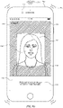
- Face alignment interface 908 includes positioning element 910, which is a framing circle or brackets that, in some examples, indicates an alignment boundary.
- the positioning element 910 identifies an inner display portion 912 and an outer display portion 912.
- the electronic device determines a biometric feature of a user is properly aligned when substantially positioned in the inner display portion 912 in a predetermined manner.
- positioning element 910 partitions inner display portion 912 from outer display portion 914.
- face alignment interface 908 also includes a text prompt 916 instructing the user to position his or her face inside of positioning element 910 (e.g., within inner display portion 812).
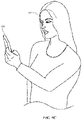
- a user positions the electronic device 900 substantially in front of the user's face 917.
- the user holds device 900 at approximately a same height as his or her face, such that the face is in the field of view of the biometric sensor 903.
- Face alignment interface 908 includes a digital viewfinder showing a preview of image data captured by biometric sensor 903.
- the preview of image data is a live preview that continuously updates (e.g., changes over time) as the field of view of these cameras changes (e.g., if device 900 is moved or if the user moves closer/farther away from the cameras).
- the digital viewfinder includes user facial image 918, as well as positioning element 910 superimposed on the field of view of the cameras. As described above, positioning element 910 partitions inner display portion 912 from surrounding outer display portion 914.
- device 900 visually obscures (e.g., shades, darkens or blurs) outer display portion 914, as shown in FIG. 9D .
- proper enrollment of a user's facial features for authentication requires that the user's face be positioned in a predetermined manner and/or within a predetermined range of distances from the cameras of device 900.
- alignment of a user's face with the cameras of device 900 requires the user to be neither too close nor too far away from the device.
- the electronic device 900 determines that the face of the user is too close or too far, the electronic device displays text prompt 920 in the face alignment interface 908 instructing the user to position their face an acceptable distance (e.g., 20-40mm) from device 900.
- an acceptable distance e.g. 20-40mm
- device 900 detects that the user's face is too far away from the cameras on the device (e.g., user facial image 918 is within positioning element 910, but does not substantially fill inner display portion 912).
- the electronic device prompts the user to move his or her face closer to the device.
- the device generates one or more outputs, such as audio output 922 (e.g., a series of beeps or other audio output) and tactile output tactile output 924 (e.g., a series of vibrations or other tactile output) to notify the user of improper alignment.
- audio output 922 e.g., a series of beeps or other audio output
- tactile output tactile output 924 e.g., a series of vibrations or other tactile output
- audio output 922 and/or tactile output tactile output 924 have a magnitude and repetition rate (e.g., frequency) that changes based on the distance between device 900 and the user's face.
- the output frequency and/or magnitude optionally increases as the user's face moves closer to the acceptable range of distances (e.g., 20-40mm) from the device.
- the output's frequency and/or magnitude optionally decrease as the user's face moves further away from the acceptable range of distances.
- device 900 continuously changes (e.g., updates) the frequency and/or magnitude of audio output 922 and/or tactile output tactile output 924 as it detects changes in distance between the user's face and biometric sensor 903.
- device 900 provides these outputs as long as the user's face is outside the acceptable range of distances from the device.
- audio output 922 and tactile output 924 is accompanied by a corresponding visual output on display 700. These ongoing audio, tactile, and/or visual outputs optionally provides intuitive hints as to how a user is to correctly align his or her face with the cameras, reducing the time required to perform successful facial alignment.
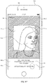
- FIG. 9E illustrates face alignment interface 908 in the case where the user's face is positioned too close to device 900 (e.g., a substantial portion of user facial image 918 falls within outer display portion 914).
- alignment interface 908 also includes text prompt 920, which instructs the user to position his or her face at an acceptable distance from device 900.
- the electronic device instructs the user to move his or her face closer to the device.
- device 900 optionally generates an ongoing audio output 922 and/or tactile output tactile output 924 in response to detecting that the user's face is too close to the camera(s).
- device 900 changes the frequency and/or magnitude of these outputs as it detects changes in distance between the user's face and the cameras.
- FIG. 9F illustrates face alignment interface 908 in the case that user's face is positioned at an acceptable distance from device 900, but is out of frame (e.g., too far to the right or left).
- face 918 is, optionally, positioned such that a substantial portion of the face 918 lies outside of positioning element 910 within outer display portion 914.
- device 900 optionally displays text prompt 926 on alignment interface 908, instructing the user to position his or her face within positioning element 910 (e.g., such that user image 918 is displayed within inner display area 912).
- the electronic device 900 displays face alignment interface 908 in response to determining that a user's face is positioned outside a range of predetermined angles relative to the electronic device.
- the electronic device 900 is positioned at a low angle relative to the electronic device (e.g., the electronic device is aligned with a chin of the user) such that the electronic device cannot properly obtain (e.g., capture biometric data).
- the electronic device 900 blurs at least a portion of face alignment interface 908, such as the inner display portion 912 and outer display portion 914.
- the electronic device further outputs a prompt 986 instructing the user to position his or her face within positioning element 910 (e.g., such that user image 918 is displayed within inner display area 912 and at the proper angle).
- a prompt 986 instructing the user to position his or her face within positioning element 910 (e.g., such that user image 918 is displayed within inner display area 912 and at the proper angle).
- the user raises the device 900 until the electronic device is within the predetermined range of angles.
- the electronic device 900 gradually decreases the blur of displayed elements. In this manner, the electronic device indicates to the user that the angle of the electronic device relative to the user is approaching the acceptable range of angles. In some examples, the electronic device is too high relative to the user such that the electronic device is not within the predetermined range of angles.
- the electronic device optionally decreases or increases blur of displayed objects as the electronic device is moved relative to the user.
- device 900 if the device detects that an alignment error persists for a predetermined amount of time, device 900 optionally displays accessibility options affordance 928 on face alignment interface 908, as shown in FIG. 9G .
- device 900 optionally displays accessibility options affordance 928 if it does not detect a user face at an acceptable distance from the device and/or within the positioning element at a predetermined time after starting alignment (e.g., after start button 904 is selected).
- the predetermined amount of time is, optionally, 10 seconds, 15 seconds, 30 seconds, or any other suitable amount of time.
- device 900 optionally displays accessibility options affordance after a certain number of enrollment attempts have failed.
- device 900 optionally displays additional options or hints and/or initiate alternative facial enrollment processes in response to detecting selection of accessibility options affordance 928.
- activation of accessibility options affordance 928 enables the user to proceed with biometric enrollment without first correcting the alignment error.
- the quality of facial feature enrollment for the face authentication methods described herein at least partially depends on the lighting conditions under which the user's facial data is captured. For example, strong backlighting or direct exposure on the user's face will, in some circumstances, adversely affect the quality of enrollment.
- device 900 in response to detecting adverse lighting conditions, device 900 optionally displays text prompt 930 on alignment interface 908, which indicates adverse lighting to the user.
- Text prompt 930 is, optionally, accompanied by an audio, visual and/or tactile output 932.
- Output 932 is, optionally, the same as output 922 and/or 924 described in connection with the alignment errors discussed above. In some embodiments, outputs are error-specific; output 932 is, optionally, therefore be a different audio, visual, and/or tactile output than outputs 922 and 924.
- the quality of facial feature enrollment also partially depends on the angle at which the user's face is orientated relative to one or more cameras of device 900 (e.g., biometric sensor 903).
- one or more optical sensors of device 900 must be able to capture image data of the user's face at a particular angle or within a predetermined range of angles. Even provided that the user's face is within the acceptable range of distances described above, face authentication enrollment can be adversely affected if device 900 is positioned to high above or too far below the user's face.
- device 900 requires the user's face to be positioned within a predetermined range of angles relative to one or more of its cameras when detecting successful alignment conditions.
- device 900 blurs the image data displayed in the digital viewfinder of alignment interface 808 in response to detecting that the user's face is outside of this predetermined range of angles relative to biometric sensor 903.
- the amount of blurring optionally depends on the difference between the detected angle of elevation of the user's face relative to the camera and one or more threshold angles that bound the predetermined angle range. For example, device 900 blurs the preview image to a greater extent the higher or lower device 900 is positioned relative to the face of the user. If device 900 detects a change in the angle of elevation bringing its cameras into closer alignment with the user's face, it optionally lessens the amount of blurring as the angle of elevation changes (e.g., in a continuous gradient).
- the preview image is not blurred if the angle of elevation between device 900 and the user's face is actively changing (e.g., the user is moving device 900 relative to his or her face). Blurring is, optionally, delayed until device 900 determines that the angle between the user's face and one or more of its cameras has been outside the predetermined angle range for a set period of time (e.g., 1 second, 2 seconds, 5 seconds, or any suitable time period). In some embodiments, only a portion of the preview image (e.g., outer display portion 914) is blurred, while the entire preview image is, optionally, blurred in other embodiments.
- a set period of time e.g. 1 second, 2 seconds, 5 seconds, or any suitable time period.
- only a portion of the preview image e.g., outer display portion 914
- the entire preview image is, optionally, blurred in other embodiments.
- Blurring the preview image in this manner optionally prompts the user to more quickly position device 900 at a desirable angle relative to his or her face, reducing the amount of time spent during the alignment process.
- device 900 optionally issues generates a tactile and/or output to inform the user that his or her face is positioned at a suitable angle relative to biometric sensor 903.
- FIG. 9N the user's face is properly positioned relative to biometric sensor 903.
- face 918 is displayed substantially within alignment element 910 and inner display portion 912.
- face 918 also occupies a substantial portion of inner display portion 912, indicating that the user's face is within the threshold range of distances from device 900.
- device 900 issues audio output 934 and tactile output 936 to indicate successful alignment of the user's face with the cameras.
- outputs 934 and 936 are different from outputs 922, 924, and 932, which are issued in response to detecting alignment errors.
- device 900 captures and stores one or more images of the user's face upon successful alignment with the cameras.
- device 900 visually emphasizes inner display portion 912 in which face 918 is displayed.
- device 900 further obscures the outer display portion 914 by blacking out or further blurring the image in the outer portion of the digital viewfinder preview while continuing to display the part of the digital viewfinder preview in inner display portion 914 (e.g., inside positioning element 910).
- device 900 further visually emphasizes the contents of inner display portion 912 by enlarging or zooming in on the image within inner display portion 912.
- the device further emphasizes the inner display portion 912 by changing the appearance of positioning element 910.
- device 900 optionally changes the appearance of the alignment element by "rounding" the corners of the alignment element as shown in FIG. 9P , and/or by merging the corners of the alignment element 910 into a circular positioning element 941 surrounding face 918, as shown in FIG. 9Q .
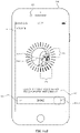
- device 900 in response to detecting that the user's face is oriented such that the above-referenced alignment criteria are met, device 900 initiates the face authentication enrollment process by displaying (e.g., replacing display of alignment interface 908 with) face enrollment interface 938.
- face enrollment interface 938 has similar or identical visual characteristics as face authentication enrollment interface 756 described above in connection with FIG. 7S or enrollment interface 1104 described below in connection with FIG. 11A.
- face enrollment interface 938 includes user facial image 939 displayed within positioning element 941.
- user facial image 939 is a live preview of image data captured by biometric sensor 903.
- Face enrollment interface 938 also optionally includes enrollment progress meter 940 that surrounds user facial image 939 and positioning element 941.
- enrollment progress meter 940 is composed of a set of progress elements (e.g., 940a, 940b, and 940c) that extend radially outward from user facial image 939 and, in some examples, enclose it in a circular pattern.
- Face enrollment interface 938 optionally includes orientation guide 942, .
- the orientation guide includes a set of curved lines (e.g., crosshairs) that appear to extend out of the plane of display 901 in a virtual z-dimension, intersecting over the center of user facial image 939.
- orientation guide provides a sense of the three-dimensional orientation of the user's face even though face image 939 is two-dimensional.
- orientation guide 942 assists the user in the face enrollment process by making rotations and/or tilts of the user's head relative to device 900 more visually apparent.
- Face enrollment interface 938 also includes text prompt 944, which optionally instructs the user to begin tilting their head, for instance, in a circle to perform enrollment.
- the quality of enrollment is decreased if device 900 moves too much relative to the user's face once the enrollment process is initiated (e.g., the device should remain still while the user moves slowly rotates/tilts his or her face).
- device 900 detects excess movement of its one or more cameras with respect to the user's face. This excess movement is, optionally, a significant change in orientation and/or position of the user's face relative to device 900 consistent with movement of the device itself, and that prevents reliable alignment and/or enrollment.
- device 900 issues visual prompt 946 on enrollment interface 938 instructing the user to reduce movement of the device (e.g., prompting the user to hold the device still during the enrollment process).
- Device 900 optionally also concurrently generates visual and/or auditory output 948.
- movement of the device itself is measured by accelerometer 168 rather than biometric sensor 903.
- Movement of the device is optionally also measured by a magnetometer, inertial measurement unit, or the like, of device 900.
- device 900 optionally exits the face enrollment process if one more alignment errors are detected during enrollment. In some examples, if, during the enrollment process, the device 900 detects one or more alignment errors, the electronic device exits the enrollment process (e.g., ceases to display face enrollment interface 938), and initiates (e.g., transitions to) an alignment process in which, optionally, the device displays alignment interface 908-2.
- the electronic device exits the enrollment process (e.g., ceases to display face enrollment interface 938), and initiates (e.g., transitions to) an alignment process in which, optionally, the device displays alignment interface 908-2.
- alignment interface 908-2 and its components optionally has similar or identical visual characteristics as the initial alignment interface 908 described above with respect to FIGS. 9B-9O . In the example of FIG.
- device 900 has determined that the face of the user is out of the frame, and as a result, the device 900 displays user facial image 918-2 within inner display portion 912-2, out of position compared to the successful alignment depicted in FIG. 9O .
- the device outputs an indication of the alignment error such as text prompt 950, which indicates that user facial image 918-2 is not properly aligned within positioning element 910.
- the alignment error is, optionally, a failure to meet any of the other alignment criteria discussed above (e.g., distance from the device, angle of orientation, adverse lighting etc.).
- text prompt 950 instruct the user move the device and/or their face into the acceptable range of distances, or correct the angle of orientation.
- the alignment error is, optionally, different from the criteria above such that a small change in alignment will not cause the device to exit the face enrollment process.
- the device visually de-emphasizes inner display portion 912-2 by revealing the portion of the image preview displayed in outer display portion 914-2 and displaying positioning element 910-2 as shown in FIG. 9U .
- device 900 lightens or unblurs the preview image in the outer display portion 914-2 to assist the user in re-aligning their face relative to biometric sensor 903.
- de-emphasizing inner display portion 912-2 reveals that a substantial portion of user facial image 918-2 is positioned outside of the positioning element 910-2 in outer display portion 914-2.
- device 900 again detects that the user's face is properly aligned with biometric sensor 903. In response, device 900 outputs audio output 934-2 and/or tactile output 936-2 indicating successful alignment. In some examples, audio output 934-2 and tactile output 934-6 have similar characteristics as audio output 934 and tactile output 936, respectively, as described with reference to FIG. 9O . In some examples, device 900 then resumes the enrollment process. For example, device 900 emphasizes inner portion 912-2 and facial image 918-2 in the manner discussed above with respect to inner display portion 912 and facial image 918-2 in FIGS. 9P-9O . In some embodiments, device 900 resumes the enrollment process at the point in which the electronic device detected the alignment error (e.g., face enrollment interface 938 is displayed a second time with enrollment progress meter 940 advanced to the same state as when the alignment error was detected).
- the alignment error e.g., face enrollment interface 938 is displayed a second time with enrollment progress meter 940 advanced to the same state as when the alignment error
- accessibility options affordance 928-2 if the device does not detect that proper alignment has been established (e.g., reestablished) within a predetermined time period, device 900 displays accessibility options affordance 928-2, as shown in FIG. 9V .
- accessibility options provide an option to proceed with the enrollment process without all alignment conditions met, as described below.
- the accessibility options provide an option to set up biometric (e.g., face) authentication with only partial enrollment (e.g., a scan of only a portion of the user's face).
- accessibility enrollment interface 954 In response to detecting activation (e.g., selection) of accessibility options button 928-2 (e.g., by tap gesture 952), the device displays accessibility enrollment interface 954, illustrated in FIG. 9W .
- One or more features of accessibility enrollment interface 954 has similar or identical visual characteristics to corresponding features of enrollment interface 938.
- face enrollment interface 954 includes user facial image 939-2 displayed within positioning element 941-2.
- user facial image 939-2 is a live preview of image data captured by biometric sensor 903-2.
- Accessibility enrollment interface 954 also optionally includes enrollment progress meter 940-2 that surrounds user facial image 939-2 and positioning element 941-2. As described above in connection with FIG.
- enrollment progress meter 940-2 is composed of a set of progress elements (e.g., 940-2a, 940-2b, and 940-2c) that extend radially outward from user facial image 939-2 and, in some examples, enclose it in a circular pattern.
- Accessibility enrollment interface 954 optionally includes orientation guide 942-2, In some examples, the orientation guide includes a set of curved lines (e.g., crosshairs) that appear to extend out of the plane of display 901 in a virtual z-dimension, intersecting over the center of user facial image 939-2.
- accessibility interface 954 optionally includes a text prompt (e.g., prompt 956) that provides written instructions for successfully completing the enrollment process.
- accessibility enrollment interface 954 also includes completion affordance 956, activation of which allows the user to exit the enrollment process and proceed to set up face authentication using only a partial scan of their facial features.
- completion affordance 956 activation of which allows the user to exit the enrollment process and proceed to set up face authentication using only a partial scan of their facial features.
- partial scans are, in some circumstances, helpful for a user having a condition that prohibits the user from tilting his or her head in all directions otherwise required for enrollment.
- Face enrollment confirmation interface 960 In response to activation (e.g., selection) of completion affordance 956 (e.g., by a user input 958 shown in FIG. 9X ), the device displays face enrollment confirmation interface 960, illustrated in FIG. 9Y .
- Face enrollment confirmation interface includes facial image 939-3, which, in the example of FIG. 9Y , has similar visual characteristics to user facial image 939-2. Facial image 939-3 is, optionally, surrounded by enrollment progress meter 962, which is displayed in the successful authentication state described above in connection with FIGS. 7P and 7Q.
- Face enrollment confirmation interface also includes partial scan enrollment affordance 964, which allows the user to enroll the gathered facial data for use in device authentication.
- Face enrollment confirmation interface 960 also includes a back affordance 966, which allows the user to navigate back to accessibility enrollment interface 954.
- the device detects a user input 968 corresponding to activation (e.g., selection) of back affordance 966.
- device 900 displays (e.g., for a second time) accessibility enrollment interface 954.
- device 900 detects movement (e.g., rotation and/or tilting) of the user's face relative to biometric sensor 903.
- FIG. 9AA device 900 detects that the user's face has tilted in a particular direction (e.g., downwards and/or to the right towards meter portion 970). As described below in further detail with respect to FIGS.
- device 900 updates user facial image 939-2 based on the detected movement, and updates the position of orientation guide 942-2 to indicate that the user's head has tilted and/or rotated in three-dimensional space.
- device 900 captures image data of a portion of the user's face (e.g., the left side of the face) and concurrently changes the appearance of a corresponding portion (e.g., meter portion 970) of enrollment progress meter 940-2.
- device 900 elongates and or changes color of one or more progress elements in meter portion 970 to indicate that the portion of the user's face is currently being enrolled (as described in more detail with respect to FIGS. 7I-7K and 11B-11H).
- device 900 maintains the display (e.g., does not change the appearance) of meter portion 972, since meter portion 972 corresponds to a facial orientation that has not yet been enrolled.
- device 900 detects a change in orientation of the user's face relative to its one or more cameras (e.g., the user's face has tilted upwards) and updates user facial image 939-2 and orientation guide 942-2 accordingly.
- device 900 transitions the state of the progress elements in meter portion 972 to an "enrolled" state as described in more detail below with respect to FIGS. 11B-I (e.g., by shading or changing the color and/or line width of the progress elements).
- device 900 again detects activation (e.g., selection) of done affordance 956 (e.g., by user input 958-2).
- device 900 In response to detecting activation of completion affordance 956, device 900 returns to displaying face enrollment confirmation interface 960 as shown in FIG. 9AC . Since a portion of the user's face has been successfully enrolled, device 900 displays enrollment success indicator 974, for instance, proximate to the user facial image 939-3. In the example of FIG. 9AC , enrollment success indicator 974 indicates orientations of the user's face that have been successfully enrolled. In some examples, the enrollment success indicator 974 is a circular bar. Accordingly, in some examples, enrollment success indicator 974 indicates (e.g., is located at) positions where enrollment progress meter transitioned to the success state during enrollment.
- partial scan enrollment affordance 964 is selectable. As shown in FIG. 9AD , device 900 detects activation (e.g., selection) of partial scan enrollment affordance 964 (e.g., by user input 976). In response to detecting activation of partial scan enrollment affordance 964, device 900 displays enrollment-complete interface 978, illustrated in FIG. 9AE Enrollment completion interface 978 includes text prompt 980, indicating to the user that the enrollment process is complete and face authentication has been securely set-up. Enrollment-complete interface 978 include optionally a generic face graphic 982 at a location that was previous occupied by user facial image 939-3. In some examples, enrollment complete interface 978 also includes a done affordance, activation of which causes the electronic device to exit face authentication set-up.
- FIG. 10 is a flow diagram illustrating a method for aligning a biometric feature on the display of an electronic device in accordance with some embodiments.
- Method 1000 is performed at a device (e.g., 100, 300, 500, 900) with a display, one or more input devices (e.g., a touchscreen, a mic, a camera), and a wireless communication radio (e.g., a Bluetooth connection, WiFi connection, a mobile broadband connection such as a 4G LTE connection).
- the display is a touch-sensitive display.
- the display is not a touch sensitive display.
- the electronic device includes a plurality of cameras. In some embodiments, the electronic device includes only one camera.
- the device includes one or more biometric sensors which, optionally, include a camera, such as a infrared camera, a thermographic camera, or a combination thereof.
- the device further includes a light-emitting device, such as an IR flood light a structured light projector, or a combination thereof.
- the light-emitting device is, optionally, used to illuminate the biometric feature (e.g., the face) during capture of biometric data of the biometric features by the one or more biometric sensors.
- method 1000 provides an intuitive way for aligning a biometric feature on the display of an electronic device.
- the method reduces the cognitive burden on a user for enrolling a biometric feature on the device, thereby creating a more efficient human-machine interface.
- the device displays (1002), on the display, a first user interface (e.g., 905).
- a first user interface e.g., 905
- the first user interface is, optionally, the enrollment introduction user interface as described above with respect to method 700.
- the device While displaying the first user interface, the device detects (1004) the occurrence of a condition that corresponds to initiating a biometric enrollment process for enrolling a respective type of biometric feature (e.g., 917).
- a condition that corresponds to initiating a biometric enrollment process for enrolling a respective type of biometric feature (e.g., 917).
- the occurrence of a condition is, optionally, an input (e.g., 906 on start affordance 904) that corresponds to a request to "start enrollment.”
- the device In response to detecting the occurrence of a condition that corresponds to initiating the biometric enrollment process (e.g., user input selecting initiation of enrollment), the device displays (1006), on the display, a digital viewfinder (e.g., display portions 912 and 914) including a preview of image data (e.g., user facial image 918) captured by the one or more cameras (e.g., 903).
- the preview of image data encompasses a first portion of a field of view of the one or more cameras (e.g., outer portion of field of view 914) and a second portion of the field of view of the one or more cameras (e.g., inner portion of field of view 912).
- the second portion of the field of view (e.g., 914) is (1008) a portion of the field of view that encloses (or partially encloses) the first portion of the field of view (e.g., 912).
- the inner portion of the field of view is, optionally, divided from outer portion by an alignment element (e.g., positioning element 910).
- the preview of image data optionally changes over time as the content in the field of view of the one or more cameras (e.g., 903) changes.
- Displaying a preview of the image captured by the biometric sensors provides the user with feedback about the position and orientation of his or her biometric features relative to the biometric sensors of the device, enabling the user to properly align his or her biometric features with the sensors more quickly and efficiently.
- Providing improved visual feedback to the user enhances the operability of the device and makes the user-device interface more efficient (e.g., by helping the user to provide proper inputs and reducing user mistakes when operating/interacting with the device), which, additionally, reduces power usage and improves battery life of the device by enabling the user to use the device more quickly and efficiently.
- the device concurrently displays (1010), with the preview of image data, an alignment element (e.g., positioning element 910) that indicates a portion of the preview (e.g., 912) in which the user's face (e.g., 918) should be placed in order to proceed with the biometric enrollment.
- an alignment element e.g., positioning element 910 that indicates a portion of the preview (e.g., 912) in which the user's face (e.g., 918) should be placed in order to proceed with the biometric enrollment.
- the alignment element is, optionally, a framing circle or framing brackets that are displayed in a central portion of the preview image (e.g., 912) to prompt the user to move the device or their face into alignment with the central portion of the preview image.
- Displaying an alignment element that frames a particular portion of the digital viewfinder provides the user with feedback about the position of his or her biometric features relative to a potion of the biometric sensor's field of view corresponding to proper alignment of the biometric feature. This in turn enables the user to properly position his or her biometric features relative to the sensors more quickly and efficiently.
- Providing improved visual feedback to the user enhances the operability of the device and makes the user-device interface more efficient (e.g., by helping the user to provide proper inputs and reducing user mistakes when operating/interacting with the device), which, additionally, reduces power usage and improves battery life of the device by enabling the user to use the device more quickly and efficiently
- the device determines (1014) whether a biometric feature of the respective type (e.g., 917) that meets alignment criteria has been detected in the field of view of the one or more cameras (e.g., 903). Determining whether the user's biometric features are properly aligned with the biometric sensors improves the quality of subsequent biometric enrollment (e.g., according to methods 1200 and/or 1400) by ensuring that image data corresponding to particular portions and/or orientations of the biometric feature are captured during enrollment. This in turn improves the ability of the device to match a user's biometric feature with the captured data during biometric authentication at the device.
- a biometric feature of the respective type e.g., 917
- alignment criteria e.g., 903
- Determining whether the user's biometric features are properly aligned with the biometric sensors improves the quality of subsequent biometric enrollment (e.g., according to methods 1200 and/or 1400) by ensuring that image data corresponding to particular portions and/or orientation
- Performing an optimized operation when a set of conditions has been met without requiring further user input user enhances the operability of the device and makes the user-device interface more efficient (e.g., by helping the user to provide proper inputs and reducing user mistakes when operating/interacting with the device), which, additionally, reduces power usage and improves battery life of the device by enabling the user to use the device more quickly and efficiently.
- the device in response (1016) to detecting the biometric feature of the respective type (e.g., 917) that meets alignment criteria, the device outputs (1018) a tactile output of a first type (e.g., 934, 936, 934-2, 936-2, e.g., the tactile output is an output corresponding to successful alignment).
- a tactile output of a first type e.g., 934, 936, 934-2, 936-2, e.g., the tactile output is an output corresponding to successful alignment.
- Providing improved tactile feedback to the user enhances the operability of the device and makes the user-device interface more efficient (e.g., by helping the user to provide proper inputs during biometric enrollment and reducing user mistakes when operating/interacting with the device), which, additionally, reduces power usage and improves battery life of the device by enabling the user to use the device more quickly and efficiently.
- the device in response (1016) to detecting the biometric feature of the respective type that meets alignment criteria, stores (1020) image data corresponding to the biometric feature (e.g., 917). In some embodiments, on successful alignment, the device captures data associated with the biometric feature. Storing biometric (e.g., image) data in response to detecting successful alignment of the biometric feature allows the device to automatically capture data that be referenced during a subsequent biometric authorization attempt.
- Performing an optimized operation when a set of conditions has been met without requiring further user input user enhances the operability of the device and makes the user-device interface more efficient (e.g., by helping the user to provide proper inputs and reducing user mistakes when operating/interacting with the device), which, additionally, reduces power usage and improves battery life of the device by enabling the user to use the device more quickly and efficiently.
- the alignment criteria includes (1024) a requirement that at least a portion of the biometric feature (e.g., 917) is within the first portion of the field of view (e.g., inner display portion 912, 912-2) of the one or more cameras.
- the electronic device determines whether the image data includes data corresponding to the biometric feature that satisfies the alignment criteria.
- the alignment criteria include (1050) lighting conditions criteria.
- alignment criteria require that lighting conditions of the electronic device are adequate for capturing image data during biometric feature enrollment, including a requirement that at least a first threshold amount of light is detected and/or that no more than a second threshold amount of light is detected (e.g., by 903).
- the alignment criteria include (1052) a requirement that a portion of the biometric feature (e.g., a portion of 917) is oriented relative to the electronic device in a predetermined manner.
- the alignment criteria optionally includes a requirement that the user gaze is directed toward at least one of the one or more cameras (e.g., 903) of the electronic device or the display (e.g., 901) of the electronic device.
- the requirement that a portion of the biometric feature (e.g., a portion of user facial image 918) is oriented relative to the electronic device in a predetermined manner is a requirement that the biometric feature (e.g., 917) is positioned within a threshold angle (e.g., angle of elevation) relative to the one or more biometric sensors (e.g., 903).
- the alignment criteria require that the biometric feature (e.g., 917) is positioned relative to the biometric sensors (e.g., 903) in a predetermined manner such that the biometric sensors can capture biometric data corresponding to the biometric feature at a particular angle, or within a range of angles.
- the device blurs the display of the electronic device (e.g., display portions 912 and/or 914), for instance, based on the degree to which the biometric feature (e.g., 917) is outside of a predefined range of angles with respect to the one or more biometric sensors (e.g., 903).
- the alignment criteria include (1042) a requirement that the biometric feature (e.g., 917) is within a first threshold distance from the one or more biometric sensors (e.g., 903, e.g., the biometric feature is not too far from the biometric sensors) and a requirement that the biometric feature is not within a second threshold distance from the one or more biometric sensors (e.g., the biometric feature is not too close to the biometric sensors) (1026).
- a requirement that the biometric feature e.g., 917 is within a first threshold distance from the one or more biometric sensors (e.g., 903, e.g., the biometric feature is not too far from the biometric sensors)
- a requirement that the biometric feature is not within a second threshold distance from the one or more biometric sensors (e.g., the biometric feature is not too close to the biometric sensors) (1026).
- the device detects (1044), by the one or more cameras (e.g., 903), a change in distance of the biometric feature (e.g., 917) from the first distance to a second distance from the electronic device that is not within the predetermined range of distances from the electronic device.
- the device In response to detecting the change in distance, the device generates (1046) an output (e.g., an audio, tactile, and/or visual outputs 922, 924) having a value of an output characteristic (e.g., a magnitude or amplitude, or a frequency or repetition rate) that varies based on a distance of the biometric feature from the predetermined range of distances.
- an output characteristic e.g., a magnitude or amplitude, or a frequency or repetition rate
- the electronic device issues an ongoing audio output (e.g., 924, e.g., a series of beeps) having a frequency that increases as the distance between the biometric feature (e.g., 917) and the electronic device approaches a target distance (or range of distances) from the electronic device. For example, the rate of beeping optionally increases.
- the frequency of the audio output optionally decreases as the distance between the biometric feature and the electronic moves further away from the target distance (or range of distances) from the electronic device.
- the rate of beeping optionally decreases.
- similar feedback is generated with tactile outputs (e.g., output 924) or visual outputs. Issuing an audio, tactile, and/or visual output that varies based on the distance between the biometric feature and the device provides ongoing feedback to the user about the position of his or her biometric features relative to a range of distances from the biometric sensors corresponding to proper alignment. This in turn reduces the amount of time alignment interfaces are displayed and reduces the number of user inputs that are required during the alignment process.
- Providing improved audio, tactile and/or visual feedback to the user therefore enhances the operability of the device and makes the user-device interface more efficient (e.g., by helping the user to provide proper inputs and reducing user mistakes when operating/interacting with the device), which, additionally, reduces power usage and improves battery life of the device by enabling the user to use the device more quickly and efficiently
- the device emphasizes (1028) the first portion of the field of view (e.g., inner display portion 912 in FIG. 9J ) of the one or more cameras relative to the second portion of the field of view (e.g., outer display portion 914 in FIG 9J ) of the one or more cameras (e.g., darken, blur, and/or black out the second portion of the field of view without darkening, blurring, and/or blacking out the first portion of the field of view of the one or more cameras).
- the first portion of the field of view e.g., inner display portion 912 in FIG. 9J
- the second portion of the field of view e.g., outer display portion 914 in FIG 9J
- the alignment criteria include a requirement that a face of user (e.g., 917) is aligned with the camera (e.g., 903) in a predetermined alignment, or an eye of the user is aligned with the camera in a predetermined alignment.
- Providing a visual effect that emphasizes a portion of the display upon detecting successful alignment of the user's biometric features with the biometric sensors allows the user to quickly recognize that the current position of his or her biometric features is optimal for a subsequent biometric enrollment process (e.g., according to methods 1200 and/or 1400).
- Providing improved visual feedback when a set of conditions has been met without requiring further user input enhances the operability of the device and makes the user-device interface more efficient (e.g., by helping the user to provide proper inputs and reducing user mistakes when operating/interacting with the device), which, additionally, reduces power usage and improves battery life of the device by enabling the user to use the device more quickly and efficiently.
- the device darkens (1030) a portion of the digital viewfinder that corresponds to the second portion of the field of view (e.g., 914 in FIG. 9J ) of the one or more cameras (e.g., 903). Darkening in this manner includes dimming or lowering brightness of the portion of the digital viewfinder that corresponds to the second portion of the field of view.
- the device ceases to display (1032) the portion of the digital viewfinder that corresponds to the second portion of the field of view (e.g., second display portion 914) of the one or more cameras.
- the portion of the viewfinder corresponding to the second portion of the field of view includes blacking out the second portion of the field of view and/or replacing the display of the second portion of the field of view with display of other content.
- the device enlarges (1034) display of the first portion of the field of view (e.g., inner display portion 912) of the one or more cameras on the display.
- enlarging display of the first portion includes enlarging display of some or all of first the portion of the field of view.
- enlarging display of the first portion of the field of view includes zooming in on the first portion of the field of view.
- emphasizing the first portion of the field of view (e.g., 912) of the one or more cameras relative to the second portion of the field of view (e.g., 914) of the one or more cameras includes shrinking or hiding some or all of first portion.
- the device shrinks the first portion prior to enlarging display of first portion and/or shrinks the first portion after enlarging display of the first portion (e.g., to provide a zoom in and zoom out effect).
- the device modifies (1036) the alignment element (e.g., 910).
- modifying the alignment element includes removing the alignment element.
- modifying the alignment element includes changing the shape and/or color of the alignment element (e.g., from 910 to 910-2 FIGS. 9J-9K ).
- the device modifies (1038) a shape of the alignment element from a first shape to a second shape.
- the first shape (1040) is substantially rectangular and the second shape is substantially circular.
- the first shape and/or second shape is, optionally, any other shape or portion of a shape.
- a shape is, optionally, a segmented shape, such as a segmented rectangle (e.g., a rectangle that is missing a portion of one or more sides).
- the device after emphasizing the first portion of the field of view (e.g., 912) of the one or more cameras relative to the second portion of the field of view (e.g., 914) of the one or more cameras (e.g., 903), the device detects (1054) that the biometric feature of the respective type that meets alignment criteria (e.g., 917) is no longer detected in the field of view of the one or more cameras.
- the device outputting an indication of an alignment error (e.g., 950). For example, for correctable errors, the device identifies the error and prompts the user to correct the error.
- the device For uncorrectable errors, the device only identifies the error. Errors are identified by text and a tactile output (e.g., 950, 924, 925). In some embodiments, errors are identified using auditory outputs, such as those provided for accessibility purposes. In some embodiments, the criteria for detecting that the biometric feature is no longer detected in the field of view of the one or more cameras is the same as the criteria for determining that the biometric feature meets the alignment criteria.
- the alignment criteria are different from the criteria for detecting that the biometric feature is no longer detected in the field of view of the one or more cameras (e.g., once the biometric feature is aligned with the one or more cameras, the biometric feature can be moved slightly out of alignment without the device exiting the biometric enrollment process and outputting an indication of an alignment error). Outputting an indication that the user's biometric feature is no longer aligned with the biometric sensor provides feedback allowing the user to quickly recognize that the position and/or orientation of his or her biometric feature has deviated from previously established alignment.
- This feedback prompts the user to quickly reposition his or her biometric feature to re-establish proper alignment with the biometric sensor, reducing amount of time that alignment user interfaces are displayed, reducing the number of inputs required at these alignment user interfaces, and improving the quality of biometric feature enrollment.
- Providing improved audio, tactile and/or visual feedback to the user therefore enhances the operability of the device and makes the user-device interface more efficient (e.g., by helping the user to provide proper inputs and reducing user mistakes when operating/interacting with the device), which, additionally, reduces power usage and improves battery life of the device by enabling the user to use the device more quickly and efficiently.
- outputting an indication of an alignment error includes outputting (1056) a tactile output of a second type (e.g., 951).
- the tactile output is an output corresponding to a loss of successful alignment.
- tactile outputs are error-specific, and, in some embodiments, auditory output is additionally or alternatively provided.
- outputting the indication of the alignment error includes (1058) deemphasizing the first portion of the field of view of the one or more cameras (e.g., 912-2) relative to the second portion of the field of view of the one or more cameras (e.g., 914-2).
- the device optionally, lightens, unblurs, and/or reveals the second portion of the field of view relative to the first portion of the field of view of the one or more cameras.
- the electronic device lightens and unblurs the second portion of the field of view to deemphasize the first portion relative to the second portion.
- the device resumes the biometric enrollment process from where the enrollment process was prior to outputting the indication of the alignment error (e.g., the enrollment progress up to the point when the alignment error was detected, is preserved).
- a progress indicator e.g., 940
- the progress indicator disappears when the indication of the alignment error is output, but is redisplayed (e.g., 940-2) when the biometric feature is properly aligned with the one or more biometric sensors.
- the progress indicator when the progress indicator is redisplayed it includes an indication of the progress made in enrolling the biometric feature prior to outputting the indication of the alignment error.
- Providing a visual effect that de-emphasizes a portion of the display upon detecting an alignment error allows the user to quickly recognize that the position and/or orientation of his or her biometric feature has deviated from previously established alignment.
- This feedback prompts the user to quickly reposition his or her biometric feature to re-establish proper alignment with the biometric sensor, which reducing amount of time that alignment user interfaces are displayed, reduces the number of inputs required at these alignment user interfaces, and improves the quality of subsequent biometric feature enrollment (e.g., according to methods 1200 and/or 1400).
- Providing improved visual feedback when a set of conditions has been met without requiring further user input enhances the operability of the device and makes the user-device interface more efficient (e.g., by helping the user to provide proper inputs and reducing user mistakes when operating/interacting with the device), which, additionally, reduces power usage and improves battery life of the device by enabling the user to use the device more quickly and efficiently.
- the device in accordance with (1062) a determination that the alignment error is an alignment error of a first type (e.g., the biometric feature is too far from or too close to the electronic device), the device outputs (1064) (e.g., displays) a prompt (e.g., 920) to move the biometric feature to correct the alignment error of the first type. For example, the device prompts the user to move closer to or move further away from the electronic device, respectively.
- a prompt e.g., 920
- the device in accordance with a determination (1062) that the alignment error is an alignment error of a second type (e.g., the biometric feature is out of the first portion of the field of view), the device outputs (1064) (e.g., displays) a prompt (e.g., 950) to move the biometric feature to correct the alignment error of the second type.
- the device prompts the user to move the biometric feature into the first portion of the field of view.
- the device forgoes (1068) outputting a prompt (e.g., 926) to move the biometric feature to correct the alignment error of the first type.
- the second portion of the field of view e.g., 914-2) is modified (e.g., blurred) in response to determining that the alignment error is an alignment error of a second type.
- the alignment error of the first type is (1074) that a portion of the biometric feature (e.g., portion of 917 shown in 939, 918-2) is oriented outside of the first portion of the field of view (e.g., 912, 912-2).
- the device outputs (1076) a prompt (e.g., 950) to move the portion of the biometric feature into the first portion of the field of view to prompt the user to correct the alignment error of the first type.
- a prompt with instructions on how to correct the alignment error provides feedback that allows the user to quickly recognize how to reposition his or her biometric features in order to re-establish proper alignment and proceed with the enrollment process.
- the alignment error of the first type is (1078) that a distance between a portion of the biometric feature (e.g., 917) and the one or more biometric sensors (e.g., 903) is within a threshold distance (e.g., the biometric feature is too close to the one or more biometric sensors).
- the device outputs (1080) a prompt (e.g., 920) to move the biometric feature away from the electronic device to prompt the user to correct the alignment error of the first type.
- the alignment error of the first type is (1082) that a distance between a portion of the biometric feature (e.g., 917) and the one or more biometric sensors (e.g., 903) exceeds a threshold distance (e.g., the biometric feature is too far from the one or more biometric sensors).
- the device outputs (1084) a prompt (e.g., 920) to move the biometric feature closer to the electronic device to prompt the user to correct the alignment error of the first type.
- the alignment error of the first type is that an angle of the biometric feature (e.g., 917) relative to the one or more biometric sensors (e.g., 903) is outside of a predefined range of angles (e.g., angles of elevation) relative to the one or more biometric sensors.
- the biometric feature is, in some circumstances, too high.
- the one or more biometric sensors is, in some circumstances, too low.
- the device outputs a prompt to move the biometric feature to adjust the angle (e.g., angle of elevation) of the biometric feature relative to the one or more biometric sensors.
- the device in accordance with a determination that the error condition of the first type persists for a threshold time period (1086), displays (1088) an accessibility interface (e.g., 908) that enables the user to proceed with the biometric enrollment without correcting the error condition.
- an accessibility interface e.g., 908
- the device enables a user to proceed with biometric enrollment without moving the biometric feature (e.g., 917) relative to the device such that the error condition is corrected or without tilting the biometric feature to capture images of a different side of the biometric feature.
- the device enables a user to proceed with biometric enrollment in this manner if the biometric feature is improperly aligned for a predetermined amount of time and/or in response to a predetermined number of failed requests.
- the device after outputting the alignment error, in accordance with a determination that a biometric feature of the respective type (e.g., 917) that meets alignment criteria has been detected in the field of view of the one or more cameras (e.g., 903), the device again emphasizes (1070) the first portion of the field of view (e.g., 912-2) of the one or more cameras relative to the second portion of the field of view (e.g., 914-2) of the one or more cameras.
- a biometric feature of the respective type e.g., 917
- the device again emphasizes (1070) the first portion of the field of view (e.g., 912-2) of the one or more cameras relative to the second portion of the field of view (e.g., 914-2) of the one or more cameras.
- the device darkens, blurs, and/or blacks out the second portion of the field of view of the one or more cameras (e.g., 914-2) without darkening, blurring, and/or blacking out the first portion of the field of view of the one or more cameras (e.g., 912-2).
- the device after outputting the alignment error, and in accordance with a determination that a biometric feature of the respective type that meets alignment criteria (e.g., 917) has been detected in the field of view of the one or more cameras (e.g., 903), the device outputs (1072) a tactile output of the first type (e.g., 936). In some embodiments, however, the device outputs a tactile output of a third type different than the first type and the second type.
- the device maintains (1090) display of the digital viewfinder without emphasizing the first portion of the field of view (e.g., 912, 912-2) of the one or more cameras relative to the second portion of the field (e.g., 914, 914-2) of view of the one or more cameras (e.g., 903).
- the device detects (1092) a change in orientation and/or position of the biometric feature (e.g., 917) relative to the one or more biometric sensors (e.g., 903).
- the device detects, optionally, a change in position, a change in orientation, or both a change in orientation and position.
- the device in response to detecting (1094) the change in orientation and/or position of the biometric feature (e.g., 917) relative to the one or more biometric sensors (e.g., 903), and in accordance with a determination that device movement criteria have been met (e.g., the device is physically moving more than the threshold amount in a manner that prevents reliable alignment / enrollment), the device outputs (1096) a prompt (e.g., 946, 948, a visual, tactile or audible alert) to reduce movement of the electronic device.
- a prompt e.g., 946, 948, a visual, tactile or audible alert
- the device detects reduced movement of the device and in response to detecting the reduced movement of the device the device ceases to output the prompt.
- movement of the device is determined based on the one or more biometric sensors (e.g., 903).
- the change in orientation and/or position of the biometric feature relative to the one or more biometric sensors is consistent with movement of the device around the biometric feature rather than movement of the biometric feature in view of the one or more biometric sensors.
- the movement of the device is determined based on one or more orientation sensors of the device, such as an accelerometer (e.g., 168), a magnetometer, an inertial measurement unit, or the like, that are separate from the one or more biometric sensors.
- the device displays an enrollment progress indicator (e.g., 940) for enrollment of the biometric feature (e.g., as described in greater detail with reference to method 1200 and FIGS. 11A-11E).
- an enrollment progress indicator e.g., 940
- Displaying the enrollment progress indicator optionally includes first emphasizing the first portion of the field of view (e.g., 912, 912-2) of the one or more cameras relative to the second portion of the field of view (e.g., 914, 914-2) of the one or more cameras as described above. Displaying the progress indicator during enrollment in this manner encourages the user to look at the display of the electronic device during the enrollment to improve the ability to detect when gaze is directed at the display, and thus whether or not the user is paying attention to the device.
- first emphasizing the first portion of the field of view e.g., 912, 912-2
- the second portion of the field of view e.g., 914, 914-2
- Encouraging the user to look at the display of the electronic device enhances the operability of the device and makes the user-device interface more efficient (e.g., by ensuring that the gaze of the user is directed at the display and thereby ensuring that the biometric feature of the user is properly enrolled) which, additionally, reduces power usage and improves battery life of the device by enabling the user to use the device more quickly and efficiently.
- the device in accordance with a determination that the biometric feature (e.g., 917) is outside of the predefined range of angles (e.g., angles of elevation relative to the one or more biometric sensors 903), the device obscures (e.g., blurs, darks, or desaturates) at least a portion of the preview of the image data (e.g., display portions 912, 912-2, 914 and/or 914-2).
- the device obscures (e.g., blurs, darks, or desaturates) at least a portion of the preview of the image data (e.g., display portions 912, 912-2, 914 and/or 914-2).
- the device delays obscuring the portion of the preview of the image data (e.g., for at least a predetermined time period such as 1 second, 2 seconds, or 5 seconds after detecting that the biometric feature is within the first portion of the field of view and within the threshold distance of the one or more biometric sensors) so that the portion of the preview of the image data is not obscured if the user is actively shifting the orientation of the biometric feature relative to the one or more biometric sensors (e.g., 903).
- the obscuring is delayed as long as the angle of the biometric feature is changing. In some embodiments, the obscuring is delayed until the angle of the biometric feature has been continuously outside of the predefined range of angles for at least the predetermined time period.
- only a portion of the preview is obscured (e.g., 912 or 914, 912-2 or 914-2). In some embodiments, all of the preview is obscured (e.g., 912 and 914, 912-2 and 914-2). Obscuring the digital viewfinder when the biometric sensors are positioned too high above or too far below the user's biometric feature allows the user to quickly recognize that his or her biometric feature is out of alignment. This in turn prompts the user to change the angle of elevation between the device and his or her biometric feature until proper alignment is established.
- Providing improved visual feedback when a set of conditions has been met enhances the operability of the device and makes the user-device interface more efficient (e.g., by helping the user to provide proper inputs and reducing user mistakes when operating/interacting with the device), which, additionally, reduces power usage and improves battery life of the device by enabling the user to use the device more quickly and efficiently.
- the device detects a change in the angle of the biometric feature (e.g., 917) with respect to the one or more biometric sensors (e.g., 903).
- the device In response to detecting the change in the angle of the biometric feature with respect to the one or more biometric sensors, and in accordance with a determination that the change in angle moves the biometric feature closer to the predefined range of angles without moving the biometric feature into the predefined range of angles, the device reduces an amount of the obscuring of the portion of the preview of the image data (e.g., 912 or 914, 912-2 or 914-2) while continuing to obscure the portion of the preview of the image data.
- an amount of the obscuring of the portion of the preview of the image data e.g., 912 or 914, 912-2 or 914-2
- the amount by which the obscuring of the portion of the preview of the image data is reduced depends on an amount of the change in the angle of the biometric feature with respect to the one or more biometric sensors (e.g., the more the biometric feature moves toward the one or more biometric sensors, the greater the reduction in the amount of obscuring).
- the device ceases to obscure the portion of the preview of the image data.
- the device when the change in angle of the biometric feature moves the biometric feature into the predefined range of angles, the device generates a tactile and/or audio output to inform the user that the angle of the biometric feature is within the predefined range of angles (e.g., 934, 936). Reducing obscuration of the digital viewfinder as the user's biometric feature moves closer to the pre-defined angle range allows the user to quickly recognize a set of positions that correspond to successful alignment of the biometric feature. This in turn prompts the user to change the angle of elevation between the device and his or her biometric feature until proper alignment is established.
- the predefined range of angles e.g. 934, 936
- Providing improved visual feedback when a set of conditions has been met enhances the operability of the device and makes the user-device interface more efficient (e.g., by helping the user to provide proper inputs and reducing user mistakes when operating/interacting with the device), which, additionally, reduces power usage and improves battery life of the device by enabling the user to use the device more quickly and efficiently.
- the device in response to detecting the change in angle of the biometric feature (e.g., 917) with respect to the one or more biometric sensors (e.g., 903), and in accordance with a determination that the change in angle moves the biometric feature further away from the predefined range of angles, the device increases an amount of the obscuring of the portion of the preview of the image data (e.g., 912 or 914, 912-2 or 914-2).
- the amount by which the obscuring of the portion of the preview of the image data is increased depends on an amount of the change in the angle of the biometric feature with respect to the one or more biometric sensors (e.g., the more the biometric feature moves away the one or more biometric sensors, the greater the increase in the amount of obscuring).
- obscuring includes blurring the preview of the image data
- reducing the amount of the obscuring of the portion of the preview of the image data includes reducing an amount of blurring of the preview of the image data (e.g., by reducing a blur radius or other blur parameter).
- increasing the amount of the obscuring of the portion of the preview of the image data includes increasing a blur radius or other blur parameter.
- this gathered data can include personal information data that uniquely identifies or can be used to contact or locate a specific person.
- personal information data can include demographic data, location-based data, telephone numbers, email addresses, home addresses, or any other identifying information.
- the present disclosure recognizes that the use of such personal information data, in the present technology, can be used to the benefit of users.
- the personal information data can be used to deliver targeted content that is of greater interest to the user. Accordingly, use of such personal information data enables calculated control of the delivered content. Further, other uses for personal information data that benefit the user are also contemplated by the present disclosure.
- the present disclosure further contemplates that the entities responsible for the collection, analysis, disclosure, transfer, storage, or other use of such personal information data will comply with well-established privacy policies and/or privacy practices.
- such entities should implement and consistently use privacy policies and practices that are generally recognized as meeting or exceeding industry or governmental requirements for maintaining personal information data private and secure.
- personal information from users should be collected for legitimate and reasonable uses of the entity and not shared or sold outside of those legitimate uses. Further, such collection should occur only after receiving the informed consent of the users.
- such entities would take any needed steps for safeguarding and securing access to such personal information data and ensuring that others with access to the personal information data adhere to their privacy policies and procedures. Further, such entities can subject themselves to evaluation by third parties to certify their adherence to widely accepted privacy policies and practices.
- the present disclosure also contemplates embodiments in which users selectively block the use of, or access to, personal information data. That is, the present disclosure contemplates that hardware and/or software elements can be provided to prevent or block access to such personal information data.
- the present technology can be configured to allow users to select to "opt in” or "opt out” of participation in the collection of personal information data during registration for services.
- users can select not to provide location information for targeted content delivery services.
- users can select to not provide precise location information, but permit the transfer of location zone information.
- the present disclosure broadly covers use of personal information data to implement one or more various disclosed embodiments, the present disclosure also contemplates that the various embodiments can also be implemented without the need for accessing such personal information data. That is, the various embodiments of the present technology are not rendered inoperable due to the lack of all or a portion of such personal information data.
- content can be selected and delivered to users by inferring preferences based on non-personal information data or a bare minimum amount of personal information, such as the content being requested by the device associated with a user, other non-personal information available to the content delivery services, or publically available information.
Description
- The present disclosure relates generally to biometric authentication, and more specifically to interfaces and techniques for enrollment and authentication of biometric features.
- Biometric authentication, for instance of a face, iris, or fingerprint, using electronic devices is a convenient and efficient method of authenticating users of the electronic devices. Biometric authentication allows a device to quickly and easily verify the identity of any number of users.
-
US 2013/336545 A1 discloses a mobile device able to capture a plurality of different biometric identifiers of a subject. -
US 9 716 825 B1 -
US 8 254 647 B1 discloses techniques for assessing image quality of captured facial images. An example method includes capturing an image, generating a facial detection confidence score based in part on a likelihood that a representation of at least a portion of a face is included in the image, generating a facial landmark detection confidence score based at least in part on a likelihood that representations of facial landmarks are accurately identified in the image, and generating a geometric consistency score based at least in part on a difference between a point of intersection between a nose base and a line segment that passes through each eye and a midpoint of the line segment. - Some techniques for implementing biometric authentication using electronic devices, however, are generally cumbersome. For example, some existing techniques, such as those directed to facial recognition, require a user to almost perfectly align a biometric feature in a same manner during both enrollment and each iteration of authentication. Deviation from the alignment of the biometric feature often results in a false negative result. As a result, a user is, optionally, required to unnecessarily perform multiple iterations of biometric authentication, or is, optionally, discouraged from using the biometric authentication altogether. As another example, some existing techniques rely solely on a two-dimensional representation of a biometric feature. As a result, authentication of a user is, optionally, limited by virtue of a failure to analyze one or more three-dimensional characteristics of the biometric feature and also optionally requires a user to unnecessarily perform additional iterations of biometric authentication. In view of the foregoing drawbacks, existing techniques require more time than necessary, wasting both user time and device energy. This latter consideration is particularly significant in the operation of battery-operated devices.
- Accordingly, the present technique provides electronic devices with faster, more efficient methods and interfaces for implementing biometric authentication. Such methods and interfaces optionally complement or replace other methods for implementing biometric authentication. Such methods and interfaces reduce the cognitive burden on a user and produce a more efficient human-machine interface. For battery-operated computing devices, such methods and interfaces conserve power and increase the time between battery charges. Such methods and interfaces also reduce the number of unnecessary, extraneous, or repetitive input required at computing devices, such as smartphones and smartwatches.
- The invention is defined by the independent claims. The dependent claims define advantageous embodiments. These embodiments and additional non-claimed embodiments, which are examples of related techniques to help understand the claimed invention, are further described below.
- Executable instructions for performing these functions are, optionally, included in a non-transitory computer-readable storage medium or other computer program product configured for execution by one or more processors. Executable instructions for performing these functions are, optionally, included in a transitory computer-readable storage medium or other computer program product configured for execution by one or more processors.
- Thus, devices are provided with faster, more efficient methods and interfaces for implementing biometric authentication, thereby increasing the effectiveness, efficiency, and user satisfaction with such devices. Such methods and interfaces optionally complement or replace other methods for implementing biometric authentication.
- For a better understanding of the various described embodiments, reference should be made to the Description of Embodiments below, in conjunction with the following drawings in which like reference numerals refer to corresponding parts throughout the figures.
-
FIGS. 9A-9AE illustrate exemplary user interfaces for aligning a biometric feature for enrollment. -
FIGS. 10A-10F are a flow diagram illustrating methods of aligning a biometric feature for enrollment. - The following description sets forth exemplary methods, parameters, and the like. It should be recognized, however, that such description is not intended as a limitation on the scope of the present disclosure but is instead provided as a description of exemplary embodiments.
- There is a need for electronic devices that provide efficient methods and interfaces for implementing biometric authentication of biometric features. For example, there is a need for electronic devices that provide a convenient and efficient method for enrolling one or more portions of a biometric feature. For another example, there is a need for electronic devices that provide a quick and intuitive technique for selectively accessing secure data in accordance with biometric authentication. For another example, there is a need for electronic devices that provide a quick and intuitive technique for enabling a function of a device in accordance with biometric authentication. Such techniques can reduce the cognitive burden on a user who enrolls a biometric feature and/or biometrically authenticates with a device, thereby enhancing overall productivity. Further, such techniques can reduce processor and battery power otherwise wasted on redundant user inputs.
- Although the following description uses terms "first," "second," etc. to describe various elements, these elements should not be limited by the terms. These terms are only used to distinguish one element from another. For example, a first touch could be termed a second touch, and, similarly, a second touch could be termed a first touch, without departing from the scope of the various described embodiments. The first touch and the second touch are both touches, but they are not the same touch.
- The terminology used in the description of the various described embodiments herein is for the purpose of describing particular embodiments only and is not intended to be limiting. As used in the description of the various described embodiments and the appended claims, the singular forms "a," "an," and "the" are intended to include the plural forms as well, unless the context clearly indicates otherwise. It will also be understood that the term "and/or" as used herein refers to and encompasses any and all possible combinations of one or more of the associated listed items. It will be further understood that the terms "includes," "including," "comprises," and/or "comprising," when used in this specification, specify the presence of stated features, integers, steps, operations, elements, and/or components, but do not preclude the presence or addition of one or more other features, integers, steps, operations, elements, components, and/or groups thereof.
- The term "if' is, optionally, construed to mean "when" or "upon" or "in response to determining" or "in response to detecting," depending on the context. Similarly, the phrase "if it is determined" or "if [a stated condition or event] is detected" is, optionally, construed to mean "upon determining" or "in response to determining" or "upon detecting [the stated condition or event]" or "in response to detecting [the stated condition or event]," depending on the context.
- Embodiments of electronic devices, user interfaces for such devices, and associated processes for using such devices are described. In some embodiments, the device is a portable communications device, such as a mobile telephone, that also contains other functions, such as PDA and/or music player functions. Exemplary embodiments of portable multifunction devices include, without limitation, the iPhone®, iPod Touch®, and iPad® devices from Apple Inc. of Cupertino, California. Other portable electronic devices, such as laptops or tablet computers with touch-sensitive surfaces (e.g., touch screen displays and/or touchpads), are, optionally, used. It should also be understood that, in some embodiments, the device is not a portable communications device, but is a desktop computer with a touch-sensitive surface (e.g., a touch screen display and/or a touchpad).
- In the discussion that follows, an electronic device that includes a display and a touch-sensitive surface is described. It should be understood, however, that the electronic device optionally includes one or more other physical user-interface devices, such as a physical keyboard, a mouse, and/or a joystick.
- The device typically supports a variety of applications, such as one or more of the following: a drawing application, a presentation application, a word processing application, a website creation application, a disk authoring application, a spreadsheet application, a gaming application, a telephone application, a video conferencing application, an e-mail application, an instant messaging application, a workout support application, a photo management application, a digital camera application, a digital video camera application, a web browsing application, a digital music player application, and/or a digital video player application.
- The various applications that are executed on the device optionally use at least one common physical user-interface device, such as the touch-sensitive surface. One or more functions of the touch-sensitive surface as well as corresponding information displayed on the device are, optionally, adjusted and/or varied from one application to the next and/or within a respective application. In this way, a common physical architecture (such as the touch-sensitive surface) of the device optionally supports the variety of applications with user interfaces that are intuitive and transparent to the user.
- As used in the specification and claims, the term "intensity" of a contact on a touch-sensitive surface refers to the force or pressure (force per unit area) of a contact (e.g., a finger contact) on the touch-sensitive surface, or to a substitute (proxy) for the force or pressure of a contact on the touch-sensitive surface. The intensity of a contact has a range of values that includes at least four distinct values and more typically includes hundreds of distinct values (e.g., at least 256). Intensity of a contact is, optionally, determined (or measured) using various approaches and various sensors or combinations of sensors. For example, one or more force sensors underneath or adjacent to the touch-sensitive surface are, optionally, used to measure force at various points on the touch-sensitive surface. In some implementations, force measurements from multiple force sensors are combined (e.g., a weighted average) to determine an estimated force of a contact. Similarly, a pressure-sensitive tip of a stylus is, optionally, used to determine a pressure of the stylus on the touch-sensitive surface. Alternatively, the size of the contact area detected on the touch-sensitive surface and/or changes thereto, the capacitance of the touch-sensitive surface proximate to the contact and/or changes thereto, and/or the resistance of the touch-sensitive surface proximate to the contact and/or changes thereto are, optionally, used as a substitute for the force or pressure of the contact on the touch-sensitive surface. In some implementations, the substitute measurements for contact force or pressure are used directly to determine whether an intensity threshold has been exceeded (e.g., the intensity threshold is described in units corresponding to the substitute measurements). In some implementations, the substitute measurements for contact force or pressure are converted to an estimated force or pressure, and the estimated force or pressure is used to determine whether an intensity threshold has been exceeded (e.g., the intensity threshold is a pressure threshold measured in units of pressure). Using the intensity of a contact as an attribute of a user input allows for user access to additional device functionality that is, in some circumstances, otherwise not be accessible by the user on a reduced-size device with limited real estate for displaying affordances (e.g., on a touch-sensitive display) and/or receiving user input (e.g., via a touch-sensitive display, a touch-sensitive surface, or a physical/mechanical control such as a knob or a button).
- As used in the specification and claims, the term "tactile output" refers to physical displacement of a device relative to a previous position of the device, physical displacement of a component (e.g., a touch-sensitive surface) of a device relative to another component (e.g., housing) of the device, or displacement of the component relative to a center of mass of the device that will be detected by a user with the user's sense of touch. For example, in situations where the device or the component of the device is in contact with a surface of a user that is sensitive to touch (e.g., a finger, palm, or other part of a user's hand), the tactile output generated by the physical displacement will be interpreted by the user as a tactile sensation corresponding to a perceived change in physical characteristics of the device or the component of the device. For example, movement of a touch-sensitive surface (e.g., a touch-sensitive display or trackpad) is, optionally, interpreted by the user as a "down click" or "up click" of a physical actuator button. In some cases, a user will feel a tactile sensation such as an "down click" or "up click" even when there is no movement of a physical actuator button associated with the touch-sensitive surface that is physically pressed (e.g., displaced) by the user's movements. As another example, movement of the touch-sensitive surface is, optionally, interpreted or sensed by the user as "roughness" of the touch-sensitive surface, even when there is no change in smoothness of the touch-sensitive surface. While such interpretations of touch by a user will be subject to the individualized sensory perceptions of the user, there are many sensory perceptions of touch that are common to a large majority of users. Thus, when a tactile output is described as corresponding to a particular sensory perception of a user (e.g., an "up click," a "down click," "roughness"), unless otherwise stated, the generated tactile output corresponds to physical displacement of the device or a component thereof that will generate the described sensory perception for a typical (or average) user. Using tactile outputs to provide haptic feedback to a user enhances the operability of the device and makes the user-device interface more efficient (e.g., by helping the user to provide proper inputs and reducing user mistakes when operating/interacting with the device) which, additionally, reduces power usage and improves battery life of the device by enabling the user to use the device more quickly and efficiently.
- In some embodiments, a tactile output pattern specifies characteristics of a tactile output, such as the amplitude of the tactile output, the shape of a movement waveform of the tactile output, the frequency of the tactile output, and/or the duration of the tactile output.
- When tactile outputs with different tactile output patterns are generated by a device (e.g., via one or more tactile output generators that move a moveable mass to generate tactile outputs), the tactile outputs can invoke different haptic sensations in a user holding or touching the device. While the sensation of the user is based on the user's perception of the tactile output, most users will be able to identify changes in waveform, frequency, and amplitude of tactile outputs generated by the device. Thus, the waveform, frequency and amplitude can be adjusted to indicate to the user that different operations have been performed. As such, tactile outputs with tactile output patterns that are designed, selected, and/or engineered to simulate characteristics (e.g., size, material, weight, stiffness, smoothness, etc.); behaviors (e.g., oscillation, displacement, acceleration, rotation, expansion, etc.); and/or interactions (e.g., collision, adhesion, repulsion, attraction, friction, etc.) of objects in a given environment (e.g., a user interface that includes graphical features and objects, a simulated physical environment with virtual boundaries and virtual objects, a real physical environment with physical boundaries and physical objects, and/or a combination of any of the above) will, in some circumstances, provide helpful feedback to users that reduces input errors and increases the efficiency of the user's operation of the device. Additionally, tactile outputs are, optionally, generated to correspond to feedback that is unrelated to a simulated physical characteristic, such as an input threshold or a selection of an object. Such tactile outputs will, in some circumstances, provide helpful feedback to users that reduces input errors and increases the efficiency of the user's operation of the device.
- In some embodiments, a tactile output with a suitable tactile output pattern serves as a cue for the occurrence of an event of interest in a user interface or behind the scenes in a device. Examples of the events of interest include activation of an affordance (e.g., a real or virtual button, or toggle switch) provided on the device or in a user interface, success or failure of a requested operation, reaching or crossing a boundary in a user interface, entry into a new state, switching of input focus between objects, activation of a new mode, reaching or crossing an input threshold, detection or recognition of a type of input or gesture, etc. In some embodiments, tactile outputs are provided to serve as a warning or an alert for an impending event or outcome that would occur unless a redirection or interruption input is timely detected. Tactile outputs are also used in other contexts to enrich the user experience, improve the accessibility of the device to users with visual or motor difficulties or other accessibility needs, and/or improve efficiency and functionality of the user interface and/or the device. Tactile outputs are optionally accompanied with audio outputs and/or visible user interface changes, which further enhance a user's experience when the user interacts with a user interface and/or the device, and facilitate better conveyance of information regarding the state of the user interface and/or the device, and which reduce input errors and increase the efficiency of the user's operation of the device.
-
FIGS. 9A-9AE illustrate exemplary user interfaces for instructional tutorial for enrolling a biometric feature on an electronic device (e.g.,device 100, device 300, device 500, or device 700), in accordance with some embodiments. The user interfaces in these figures are used to illustrate the processes described below, including the processes inFIG. 10 . -
FIG. 9A illustrates an electronic device 900 (e.g.,portable multifunction device 100, device 300, device 500, or device 700). In the non-limiting exemplary embodiment illustrated inFIGS. 9A-9AE electronic device 900 is a smartphone. In other embodiments,electronic device 900 can be a different type of electronic device, such as a wearable device (e.g., a smartwatch).Electronic device 900 has adisplay 901, one or more input devices (e.g., touchscreen ofdisplay 901, a button, a microphone), and a wireless communication radio. In some examples, the electronic device includes a plurality of cameras. In some examples, the electronic device includes only one camera. In some examples, the electronic device includes one or more biometric sensors (e.g., biometric sensor 903) which, optionally, include a camera, such as an infrared camera, a thermographic camera, or a combination thereof. In some examples, the one or morebiometric sensors 903 are the one or more biometric sensors 703. In some examples, the device further includes a light-emitting device (e.g., light projector). such as an IR flood light, a structured light projector, or a combination thereof. The light-emitting device is, optionally, used to illuminate the biometric feature (e.g., the face) during capture of biometric data of biometric features by the one or more biometric sensors. - As illustrated in
FIG. 9A ,device 900 displays a faceauthentication introduction interface 905. In some embodiments, faceauthentication introduction interface 905 is similar to the face authentication tutorial interface 732 described above in connection with FIG. 7S. By way of example, faceauthentication introduction interface 905 includes face graphic 902, which is, optionally, the same as or similar to glyph 720, described above with respect to face authentication tutorial interface 732. Additionally or alternatively,device 900 optionally also display success-state instructional progress meter 907, which is, optionally, the same or similar to success-state instructional progress meter 744 in FIG. 7P-7Q. Faceauthentication introduction interface 905 also includes a start button 904 (e.g., a start affordance). As shown inFIG. 9A ,device 900 detects activation (e.g., selection) ofstart affordance 904. For example, activation is, optionally, a user input atcontact area 906 onstart affordance 904. This user input will, in some circumstances, correspond to a request to begin face authentication set-up (e.g., start face enrollment). - In some examples, in response to detecting user selection of
start button 904,device 900 displays facealignment interface 908 as shown inFIG. 9B .Face alignment interface 908 includespositioning element 910, which is a framing circle or brackets that, in some examples, indicates an alignment boundary. In some examples, thepositioning element 910 identifies aninner display portion 912 and anouter display portion 912. In some examples, the electronic device determines a biometric feature of a user is properly aligned when substantially positioned in theinner display portion 912 in a predetermined manner. In some examples,positioning element 910 partitionsinner display portion 912 fromouter display portion 914. In general, if the user's face is positioned relative tobiometric sensor 903 such that a portion of the image of the user appears inouter display portion 914, the user's face will, in some circumstances, not be properly aligned with the cameras. As such, facealignment interface 908 also includes a text prompt 916 instructing the user to position his or her face inside of positioning element 910 (e.g., within inner display portion 812). - With reference to
FIG. 9C , in some examples, during the alignment process, a user positions theelectronic device 900 substantially in front of the user'sface 917. In some examples, the user holdsdevice 900 at approximately a same height as his or her face, such that the face is in the field of view of thebiometric sensor 903. - As illustrated in
FIG. 9D , once the user has initiated alignment process, the device displays a face alignment interface 908 (recall that the user optionally initiates the enrollment process by activating an affordance 904).Face alignment interface 908 includes a digital viewfinder showing a preview of image data captured bybiometric sensor 903. In some embodiments, the preview of image data is a live preview that continuously updates (e.g., changes over time) as the field of view of these cameras changes (e.g., ifdevice 900 is moved or if the user moves closer/farther away from the cameras). The digital viewfinder includes userfacial image 918, as well aspositioning element 910 superimposed on the field of view of the cameras. As described above,positioning element 910 partitionsinner display portion 912 from surroundingouter display portion 914. To provide further visual separation between inner display portion 912 (where userfacial image 918 is to be positioned) andouter display portion 914,device 900 visually obscures (e.g., shades, darkens or blurs)outer display portion 914, as shown inFIG. 9D . - In general, proper enrollment of a user's facial features for authentication requires that the user's face be positioned in a predetermined manner and/or within a predetermined range of distances from the cameras of
device 900. In some examples, alignment of a user's face with the cameras ofdevice 900 requires the user to be neither too close nor too far away from the device. Thus, if theelectronic device 900 determines that the face of the user is too close or too far, the electronic device displays text prompt 920 in theface alignment interface 908 instructing the user to position their face an acceptable distance (e.g., 20-40mm) fromdevice 900. In the example ofFIG. 9D ,device 900 detects that the user's face is too far away from the cameras on the device (e.g., userfacial image 918 is withinpositioning element 910, but does not substantially fill inner display portion 912). In some examples, the electronic device prompts the user to move his or her face closer to the device. In some examples, the device generates one or more outputs, such as audio output 922 (e.g., a series of beeps or other audio output) and tactile output tactile output 924 (e.g., a series of vibrations or other tactile output) to notify the user of improper alignment. In some embodiments,audio output 922 and/or tactile outputtactile output 924 have a magnitude and repetition rate (e.g., frequency) that changes based on the distance betweendevice 900 and the user's face. For example, the output frequency and/or magnitude optionally increases as the user's face moves closer to the acceptable range of distances (e.g., 20-40mm) from the device. Conversely, the output's frequency and/or magnitude optionally decrease as the user's face moves further away from the acceptable range of distances. In this case,device 900 continuously changes (e.g., updates) the frequency and/or magnitude ofaudio output 922 and/or tactile outputtactile output 924 as it detects changes in distance between the user's face andbiometric sensor 903. In some embodiments,device 900 provides these outputs as long as the user's face is outside the acceptable range of distances from the device. In some embodiments,audio output 922 andtactile output 924 is accompanied by a corresponding visual output on display 700. These ongoing audio, tactile, and/or visual outputs optionally provides intuitive hints as to how a user is to correctly align his or her face with the cameras, reducing the time required to perform successful facial alignment. -
FIG. 9E illustratesface alignment interface 908 in the case where the user's face is positioned too close to device 900 (e.g., a substantial portion of userfacial image 918 falls within outer display portion 914). In this case,alignment interface 908 also includes text prompt 920, which instructs the user to position his or her face at an acceptable distance fromdevice 900. In some examples, the electronic device instructs the user to move his or her face closer to the device. As described above in connection withFIG. 9D ,device 900 optionally generates anongoing audio output 922 and/or tactile outputtactile output 924 in response to detecting that the user's face is too close to the camera(s). In particular,device 900 changes the frequency and/or magnitude of these outputs as it detects changes in distance between the user's face and the cameras. -
FIG. 9F illustratesface alignment interface 908 in the case that user's face is positioned at an acceptable distance fromdevice 900, but is out of frame (e.g., too far to the right or left). For example,face 918 is, optionally, positioned such that a substantial portion of theface 918 lies outside ofpositioning element 910 withinouter display portion 914. In this case,device 900 optionally displays text prompt 926 onalignment interface 908, instructing the user to position his or her face within positioning element 910 (e.g., such thatuser image 918 is displayed within inner display area 912). - With reference to
FIGS 9G-9L , in some examples, theelectronic device 900 displays facealignment interface 908 in response to determining that a user's face is positioned outside a range of predetermined angles relative to the electronic device. As shown inFIG. 9G , theelectronic device 900 is positioned at a low angle relative to the electronic device (e.g., the electronic device is aligned with a chin of the user) such that the electronic device cannot properly obtain (e.g., capture biometric data). With reference toFIG. 9H , in response to determining that theelectronic device 900 is outside the range of predetermined angles, theelectronic device 900 blurs at least a portion offace alignment interface 908, such as theinner display portion 912 andouter display portion 914. In some examples, the electronic device further outputs a prompt 986 instructing the user to position his or her face within positioning element 910 (e.g., such thatuser image 918 is displayed withininner display area 912 and at the proper angle). InFIGS. 91 and9K , the user raises thedevice 900 until the electronic device is within the predetermined range of angles. As the user raises the electronic device, with reference toFIGS. 9J and9K , theelectronic device 900 gradually decreases the blur of displayed elements. In this manner, the electronic device indicates to the user that the angle of the electronic device relative to the user is approaching the acceptable range of angles. In some examples, the electronic device is too high relative to the user such that the electronic device is not within the predetermined range of angles. Similarly to the described example, the electronic device optionally decreases or increases blur of displayed objects as the electronic device is moved relative to the user. - In some examples, if the device detects that an alignment error persists for a predetermined amount of time,
device 900 optionally displays accessibility options affordance 928 onface alignment interface 908, as shown inFIG. 9G . For example,device 900 optionally displays accessibility options affordance 928 if it does not detect a user face at an acceptable distance from the device and/or within the positioning element at a predetermined time after starting alignment (e.g., afterstart button 904 is selected). In some embodiments, the predetermined amount of time is, optionally, 10 seconds, 15 seconds, 30 seconds, or any other suitable amount of time. Similarly,device 900 optionally displays accessibility options affordance after a certain number of enrollment attempts have failed. As discussed in more detail below,device 900 optionally displays additional options or hints and/or initiate alternative facial enrollment processes in response to detecting selection of accessibility options affordance 928. In some embodiments, activation of accessibility options affordance 928 enables the user to proceed with biometric enrollment without first correcting the alignment error. - In general, the quality of facial feature enrollment for the face authentication methods described herein at least partially depends on the lighting conditions under which the user's facial data is captured. For example, strong backlighting or direct exposure on the user's face will, in some circumstances, adversely affect the quality of enrollment. Turning now to
FIG. 9H , in response to detecting adverse lighting conditions,device 900 optionally displays text prompt 930 onalignment interface 908, which indicates adverse lighting to the user. Text prompt 930 is, optionally, accompanied by an audio, visual and/ortactile output 932.Output 932 is, optionally, the same asoutput 922 and/or 924 described in connection with the alignment errors discussed above. In some embodiments, outputs are error-specific;output 932 is, optionally, therefore be a different audio, visual, and/or tactile output thanoutputs - In general, the quality of facial feature enrollment also partially depends on the angle at which the user's face is orientated relative to one or more cameras of device 900 (e.g., biometric sensor 903). In particular, one or more optical sensors of
device 900 must be able to capture image data of the user's face at a particular angle or within a predetermined range of angles. Even provided that the user's face is within the acceptable range of distances described above, face authentication enrollment can be adversely affected ifdevice 900 is positioned to high above or too far below the user's face. Thus, in some embodiments,device 900 requires the user's face to be positioned within a predetermined range of angles relative to one or more of its cameras when detecting successful alignment conditions. - In some embodiments,
device 900 blurs the image data displayed in the digital viewfinder of alignment interface 808 in response to detecting that the user's face is outside of this predetermined range of angles relative tobiometric sensor 903. In some examples, the amount of blurring optionally depends on the difference between the detected angle of elevation of the user's face relative to the camera and one or more threshold angles that bound the predetermined angle range. For example,device 900 blurs the preview image to a greater extent the higher orlower device 900 is positioned relative to the face of the user. Ifdevice 900 detects a change in the angle of elevation bringing its cameras into closer alignment with the user's face, it optionally lessens the amount of blurring as the angle of elevation changes (e.g., in a continuous gradient). In some embodiments, the preview image is not blurred if the angle of elevation betweendevice 900 and the user's face is actively changing (e.g., the user is movingdevice 900 relative to his or her face). Blurring is, optionally, delayed untildevice 900 determines that the angle between the user's face and one or more of its cameras has been outside the predetermined angle range for a set period of time (e.g., 1 second, 2 seconds, 5 seconds, or any suitable time period). In some embodiments, only a portion of the preview image (e.g., outer display portion 914) is blurred, while the entire preview image is, optionally, blurred in other embodiments. Blurring the preview image in this manner optionally prompts the user to more quickly positiondevice 900 at a desirable angle relative to his or her face, reducing the amount of time spent during the alignment process. In some embodiments,device 900 optionally issues generates a tactile and/or output to inform the user that his or her face is positioned at a suitable angle relative tobiometric sensor 903. - In
FIG. 9N , the user's face is properly positioned relative tobiometric sensor 903. In this case,face 918 is displayed substantially withinalignment element 910 andinner display portion 912. As shown inFIG. 9N , face 918 also occupies a substantial portion ofinner display portion 912, indicating that the user's face is within the threshold range of distances fromdevice 900. In response to detecting a face that meets the above-described alignment criteria,device 900 issuesaudio output 934 andtactile output 936 to indicate successful alignment of the user's face with the cameras. In general, outputs 934 and 936 are different fromoutputs device 900 captures and stores one or more images of the user's face upon successful alignment with the cameras. - In some examples, after detecting successful alignment,
device 900 visually emphasizesinner display portion 912 in which face 918 is displayed. In the example ofFIG. 9P ,device 900 further obscures theouter display portion 914 by blacking out or further blurring the image in the outer portion of the digital viewfinder preview while continuing to display the part of the digital viewfinder preview in inner display portion 914 (e.g., inside positioning element 910). In some embodiments,device 900 further visually emphasizes the contents ofinner display portion 912 by enlarging or zooming in on the image withininner display portion 912. - In some examples, the device further emphasizes the
inner display portion 912 by changing the appearance ofpositioning element 910. In particular,device 900 optionally changes the appearance of the alignment element by "rounding" the corners of the alignment element as shown inFIG. 9P , and/or by merging the corners of thealignment element 910 into acircular positioning element 941 surroundingface 918, as shown inFIG. 9Q . - Turning now to the example of
FIG. 9R , in response to detecting that the user's face is oriented such that the above-referenced alignment criteria are met,device 900 initiates the face authentication enrollment process by displaying (e.g., replacing display ofalignment interface 908 with) faceenrollment interface 938. In some embodiments, faceenrollment interface 938 has similar or identical visual characteristics as face authentication enrollment interface 756 described above in connection with FIG. 7S or enrollment interface 1104 described below in connection with FIG. 11A. In the example ofFIG. 9R , faceenrollment interface 938 includes userfacial image 939 displayed withinpositioning element 941. In the example ofFIG. 9R , userfacial image 939 is a live preview of image data captured bybiometric sensor 903.Face enrollment interface 938 also optionally includesenrollment progress meter 940 that surrounds userfacial image 939 andpositioning element 941. As described above in connection with FIG. 7S and FIGS 11A-11H,enrollment progress meter 940 is composed of a set of progress elements (e.g., 940a, 940b, and 940c) that extend radially outward from userfacial image 939 and, in some examples, enclose it in a circular pattern.Face enrollment interface 938 optionally includesorientation guide 942, . In some examples, the orientation guide includes a set of curved lines (e.g., crosshairs) that appear to extend out of the plane ofdisplay 901 in a virtual z-dimension, intersecting over the center of userfacial image 939. In some examples, orientation guide provides a sense of the three-dimensional orientation of the user's face even thoughface image 939 is two-dimensional. In this case,orientation guide 942 assists the user in the face enrollment process by making rotations and/or tilts of the user's head relative todevice 900 more visually apparent.Face enrollment interface 938 also includes text prompt 944, which optionally instructs the user to begin tilting their head, for instance, in a circle to perform enrollment. - Generally, the quality of enrollment is decreased if
device 900 moves too much relative to the user's face once the enrollment process is initiated (e.g., the device should remain still while the user moves slowly rotates/tilts his or her face). In the example ofFIG. 9S ,device 900 detects excess movement of its one or more cameras with respect to the user's face. This excess movement is, optionally, a significant change in orientation and/or position of the user's face relative todevice 900 consistent with movement of the device itself, and that prevents reliable alignment and/or enrollment. In response,device 900 issuesvisual prompt 946 onenrollment interface 938 instructing the user to reduce movement of the device (e.g., prompting the user to hold the device still during the enrollment process).Device 900 optionally also concurrently generates visual and/orauditory output 948. In some embodiments, movement of the device itself is measured by accelerometer 168 rather thanbiometric sensor 903. Movement of the device is optionally also measured by a magnetometer, inertial measurement unit, or the like, ofdevice 900. - Successful enrollment typically requires that alignment of the user's face relative to the cameras on
device 900 be maintained throughout the enrollment process. Thus, in some examples,device 900 optionally exits the face enrollment process if one more alignment errors are detected during enrollment. In some examples, if, during the enrollment process, thedevice 900 detects one or more alignment errors, the electronic device exits the enrollment process (e.g., ceases to display face enrollment interface 938), and initiates (e.g., transitions to) an alignment process in which, optionally, the device displays alignment interface 908-2. In the examples ofFIGS. 9T-9U , alignment interface 908-2 and its components optionally has similar or identical visual characteristics as theinitial alignment interface 908 described above with respect toFIGS. 9B-9O . In the example ofFIG. 9T-U ,device 900 has determined that the face of the user is out of the frame, and as a result, thedevice 900 displays user facial image 918-2 within inner display portion 912-2, out of position compared to the successful alignment depicted inFIG. 9O . In some embodiments, the device outputs an indication of the alignment error such astext prompt 950, which indicates that user facial image 918-2 is not properly aligned withinpositioning element 910. This example is merely illustrative. In some embodiments, the alignment error is, optionally, a failure to meet any of the other alignment criteria discussed above (e.g., distance from the device, angle of orientation, adverse lighting etc.). In such cases, text prompt 950 instruct the user move the device and/or their face into the acceptable range of distances, or correct the angle of orientation. In other some embodiments, the alignment error is, optionally, different from the criteria above such that a small change in alignment will not cause the device to exit the face enrollment process. In response to detecting the one or more alignment errors, the device visually de-emphasizes inner display portion 912-2 by revealing the portion of the image preview displayed in outer display portion 914-2 and displaying positioning element 910-2 as shown inFIG. 9U . For example,device 900 lightens or unblurs the preview image in the outer display portion 914-2 to assist the user in re-aligning their face relative tobiometric sensor 903. In the example ofFIG. 9U , de-emphasizing inner display portion 912-2 reveals that a substantial portion of user facial image 918-2 is positioned outside of the positioning element 910-2 in outer display portion 914-2. - In some embodiments,
device 900 again detects that the user's face is properly aligned withbiometric sensor 903. In response,device 900 outputs audio output 934-2 and/or tactile output 936-2 indicating successful alignment. In some examples, audio output 934-2 and tactile output 934-6 have similar characteristics asaudio output 934 andtactile output 936, respectively, as described with reference toFIG. 9O . In some examples,device 900 then resumes the enrollment process. For example,device 900 emphasizes inner portion 912-2 and facial image 918-2 in the manner discussed above with respect toinner display portion 912 and facial image 918-2 inFIGS. 9P-9O . In some embodiments,device 900 resumes the enrollment process at the point in which the electronic device detected the alignment error (e.g., faceenrollment interface 938 is displayed a second time withenrollment progress meter 940 advanced to the same state as when the alignment error was detected). - In some examples, if the device does not detect that proper alignment has been established (e.g., reestablished) within a predetermined time period,
device 900 displays accessibility options affordance 928-2, as shown inFIG. 9V . In some examples, accessibility options provide an option to proceed with the enrollment process without all alignment conditions met, as described below. In some embodiments, the accessibility options provide an option to set up biometric (e.g., face) authentication with only partial enrollment (e.g., a scan of only a portion of the user's face). - In response to detecting activation (e.g., selection) of accessibility options button 928-2 (e.g., by tap gesture 952), the device displays
accessibility enrollment interface 954, illustrated inFIG. 9W . One or more features ofaccessibility enrollment interface 954 has similar or identical visual characteristics to corresponding features ofenrollment interface 938. For example, inFIG. 9W , faceenrollment interface 954 includes user facial image 939-2 displayed within positioning element 941-2. In some embodiments, user facial image 939-2 is a live preview of image data captured by biometric sensor 903-2.Accessibility enrollment interface 954 also optionally includes enrollment progress meter 940-2 that surrounds user facial image 939-2 and positioning element 941-2. As described above in connection with FIG. 7S and FIGS 11A-11H, enrollment progress meter 940-2 is composed of a set of progress elements (e.g., 940-2a, 940-2b, and 940-2c) that extend radially outward from user facial image 939-2 and, in some examples, enclose it in a circular pattern.Accessibility enrollment interface 954 optionally includes orientation guide 942-2, In some examples, the orientation guide includes a set of curved lines (e.g., crosshairs) that appear to extend out of the plane ofdisplay 901 in a virtual z-dimension, intersecting over the center of user facial image 939-2. Likeface enrollment interface 938,accessibility interface 954 optionally includes a text prompt (e.g., prompt 956) that provides written instructions for successfully completing the enrollment process. In some examples,accessibility enrollment interface 954 also includescompletion affordance 956, activation of which allows the user to exit the enrollment process and proceed to set up face authentication using only a partial scan of their facial features. In some examples, partial scans are, in some circumstances, helpful for a user having a condition that prohibits the user from tilting his or her head in all directions otherwise required for enrollment. - In response to activation (e.g., selection) of completion affordance 956 (e.g., by a
user input 958 shown inFIG. 9X ), the device displays faceenrollment confirmation interface 960, illustrated inFIG. 9Y . Face enrollment confirmation interface includes facial image 939-3, which, in the example ofFIG. 9Y , has similar visual characteristics to user facial image 939-2. Facial image 939-3 is, optionally, surrounded byenrollment progress meter 962, which is displayed in the successful authentication state described above in connection with FIGS. 7P and 7Q. Face enrollment confirmation interface also includes partialscan enrollment affordance 964, which allows the user to enroll the gathered facial data for use in device authentication. Faceenrollment confirmation interface 960 also includes aback affordance 966, which allows the user to navigate back toaccessibility enrollment interface 954. - As illustrated in
FIG. 9Z , the device detects auser input 968 corresponding to activation (e.g., selection) ofback affordance 966. In response to detecting the user input,device 900 displays (e.g., for a second time)accessibility enrollment interface 954. While displayingaccessibility enrollment interface 954,device 900 detects movement (e.g., rotation and/or tilting) of the user's face relative tobiometric sensor 903. In the case ofFIG. 9AA ,device 900 detects that the user's face has tilted in a particular direction (e.g., downwards and/or to the right towards meter portion 970). As described below in further detail with respect to FIGS. 11B-11H,device 900 updates user facial image 939-2 based on the detected movement, and updates the position of orientation guide 942-2 to indicate that the user's head has tilted and/or rotated in three-dimensional space. In response to detecting movement of the user's face,device 900 captures image data of a portion of the user's face (e.g., the left side of the face) and concurrently changes the appearance of a corresponding portion (e.g., meter portion 970) of enrollment progress meter 940-2. In some embodiments,device 900 elongates and or changes color of one or more progress elements inmeter portion 970 to indicate that the portion of the user's face is currently being enrolled (as described in more detail with respect to FIGS. 7I-7K and 11B-11H). In some embodiments,device 900 maintains the display (e.g., does not change the appearance) ofmeter portion 972, sincemeter portion 972 corresponds to a facial orientation that has not yet been enrolled. - As illustrated in
FIG. 9AB , in some examples,device 900 detects a change in orientation of the user's face relative to its one or more cameras (e.g., the user's face has tilted upwards) and updates user facial image 939-2 and orientation guide 942-2 accordingly. By way of example, because image data at the facial orientation corresponding tometer portion 972 has been successfully enrolled,device 900 transitions the state of the progress elements inmeter portion 972 to an "enrolled" state as described in more detail below with respect to FIGS. 11B-I (e.g., by shading or changing the color and/or line width of the progress elements). As shown inFIG. 9AB ,device 900 again detects activation (e.g., selection) of done affordance 956 (e.g., by user input 958-2). - In response to detecting activation of
completion affordance 956,device 900 returns to displaying faceenrollment confirmation interface 960 as shown inFIG. 9AC . Since a portion of the user's face has been successfully enrolled,device 900 displaysenrollment success indicator 974, for instance, proximate to the user facial image 939-3. In the example ofFIG. 9AC ,enrollment success indicator 974 indicates orientations of the user's face that have been successfully enrolled. In some examples, theenrollment success indicator 974 is a circular bar. Accordingly, in some examples,enrollment success indicator 974 indicates (e.g., is located at) positions where enrollment progress meter transitioned to the success state during enrollment. - In some examples, because
accessibility enrollment interface 960 allows the user to set up face authentication with only a partial enrollment of their facial features, partialscan enrollment affordance 964 is selectable. As shown inFIG. 9AD ,device 900 detects activation (e.g., selection) of partial scan enrollment affordance 964 (e.g., by user input 976). In response to detecting activation of partialscan enrollment affordance 964,device 900 displays enrollment-complete interface 978, illustrated inFIG. 9AE Enrollment completion interface 978 includes text prompt 980, indicating to the user that the enrollment process is complete and face authentication has been securely set-up. Enrollment-complete interface 978 include optionally a generic face graphic 982 at a location that was previous occupied by user facial image 939-3. In some examples, enrollmentcomplete interface 978 also includes a done affordance, activation of which causes the electronic device to exit face authentication set-up. -
FIG. 10 is a flow diagram illustrating a method for aligning a biometric feature on the display of an electronic device in accordance with some embodiments.Method 1000 is performed at a device (e.g., 100, 300, 500, 900) with a display, one or more input devices (e.g., a touchscreen, a mic, a camera), and a wireless communication radio (e.g., a Bluetooth connection, WiFi connection, a mobile broadband connection such as a 4G LTE connection). In some embodiments, the display is a touch-sensitive display. In some embodiments, the display is not a touch sensitive display. In some embodiments, the electronic device includes a plurality of cameras. In some embodiments, the electronic device includes only one camera. In some examples, the device includes one or more biometric sensors which, optionally, include a camera, such as a infrared camera, a thermographic camera, or a combination thereof. In some examples, the device further includes a light-emitting device, such as an IR flood light a structured light projector, or a combination thereof. The light-emitting device is, optionally, used to illuminate the biometric feature (e.g., the face) during capture of biometric data of the biometric features by the one or more biometric sensors. Some operations in method 2000 are, optionally, combined, the orders of some operations are, optionally, changed, and some operations are, optionally, omitted. - As described below,
method 1000 provides an intuitive way for aligning a biometric feature on the display of an electronic device. The method reduces the cognitive burden on a user for enrolling a biometric feature on the device, thereby creating a more efficient human-machine interface. For battery-operated computing devices, enabling a user to enroll a biometric feature faster and more efficiently conserves power and increases the time between battery charges. - The device displays (1002), on the display, a first user interface (e.g., 905). For example, the first user interface is, optionally, the enrollment introduction user interface as described above with respect to method 700.
- While displaying the first user interface, the device detects (1004) the occurrence of a condition that corresponds to initiating a biometric enrollment process for enrolling a respective type of biometric feature (e.g., 917). For example, the occurrence of a condition is, optionally, an input (e.g., 906 on start affordance 904) that corresponds to a request to "start enrollment."
- In response to detecting the occurrence of a condition that corresponds to initiating the biometric enrollment process (e.g., user input selecting initiation of enrollment), the device displays (1006), on the display, a digital viewfinder (e.g.,
display portions 912 and 914) including a preview of image data (e.g., user facial image 918) captured by the one or more cameras (e.g., 903). In some embodiments, the preview of image data encompasses a first portion of a field of view of the one or more cameras (e.g., outer portion of field of view 914) and a second portion of the field of view of the one or more cameras (e.g., inner portion of field of view 912). In some embodiments, the second portion of the field of view (e.g., 914) is (1008) a portion of the field of view that encloses (or partially encloses) the first portion of the field of view (e.g., 912). In some embodiments, the inner portion of the field of view is, optionally, divided from outer portion by an alignment element (e.g., positioning element 910). In some embodiments, the preview of image data optionally changes over time as the content in the field of view of the one or more cameras (e.g., 903) changes. Displaying a preview of the image captured by the biometric sensors provides the user with feedback about the position and orientation of his or her biometric features relative to the biometric sensors of the device, enabling the user to properly align his or her biometric features with the sensors more quickly and efficiently. Providing improved visual feedback to the user enhances the operability of the device and makes the user-device interface more efficient (e.g., by helping the user to provide proper inputs and reducing user mistakes when operating/interacting with the device), which, additionally, reduces power usage and improves battery life of the device by enabling the user to use the device more quickly and efficiently. - In some embodiments, the device concurrently displays (1010), with the preview of image data, an alignment element (e.g., positioning element 910) that indicates a portion of the preview (e.g., 912) in which the user's face (e.g., 918) should be placed in order to proceed with the biometric enrollment. For example, the alignment element is, optionally, a framing circle or framing brackets that are displayed in a central portion of the preview image (e.g., 912) to prompt the user to move the device or their face into alignment with the central portion of the preview image. Displaying an alignment element that frames a particular portion of the digital viewfinder provides the user with feedback about the position of his or her biometric features relative to a potion of the biometric sensor's field of view corresponding to proper alignment of the biometric feature. This in turn enables the user to properly position his or her biometric features relative to the sensors more quickly and efficiently. Providing improved visual feedback to the user enhances the operability of the device and makes the user-device interface more efficient (e.g., by helping the user to provide proper inputs and reducing user mistakes when operating/interacting with the device), which, additionally, reduces power usage and improves battery life of the device by enabling the user to use the device more quickly and efficiently
- In some embodiments, after initiating the biometric enrollment process (1012), the device determines (1014) whether a biometric feature of the respective type (e.g., 917) that meets alignment criteria has been detected in the field of view of the one or more cameras (e.g., 903). Determining whether the user's biometric features are properly aligned with the biometric sensors improves the quality of subsequent biometric enrollment (e.g., according to methods 1200 and/or 1400) by ensuring that image data corresponding to particular portions and/or orientations of the biometric feature are captured during enrollment. This in turn improves the ability of the device to match a user's biometric feature with the captured data during biometric authentication at the device. Performing an optimized operation when a set of conditions has been met without requiring further user input user enhances the operability of the device and makes the user-device interface more efficient (e.g., by helping the user to provide proper inputs and reducing user mistakes when operating/interacting with the device), which, additionally, reduces power usage and improves battery life of the device by enabling the user to use the device more quickly and efficiently.
- In some embodiments, in response (1016) to detecting the biometric feature of the respective type (e.g., 917) that meets alignment criteria, the device outputs (1018) a tactile output of a first type (e.g., 934, 936, 934-2, 936-2, e.g., the tactile output is an output corresponding to successful alignment). Issuing a tactile output upon detecting that the biometric feature is properly aligned with the biometric sensors provides the user with feedback indicating successful alignment, which prompts the user to maintain the biometric feature in that alignment throughout a subsequent biometric enrollment process (e.g., methods 1200 and/or 1400). Providing improved tactile feedback to the user enhances the operability of the device and makes the user-device interface more efficient (e.g., by helping the user to provide proper inputs during biometric enrollment and reducing user mistakes when operating/interacting with the device), which, additionally, reduces power usage and improves battery life of the device by enabling the user to use the device more quickly and efficiently.
- In some embodiments, in response (1016) to detecting the biometric feature of the respective type that meets alignment criteria, the device stores (1020) image data corresponding to the biometric feature (e.g., 917). In some embodiments, on successful alignment, the device captures data associated with the biometric feature. Storing biometric (e.g., image) data in response to detecting successful alignment of the biometric feature allows the device to automatically capture data that be referenced during a subsequent biometric authorization attempt. Performing an optimized operation when a set of conditions has been met without requiring further user input user enhances the operability of the device and makes the user-device interface more efficient (e.g., by helping the user to provide proper inputs and reducing user mistakes when operating/interacting with the device), which, additionally, reduces power usage and improves battery life of the device by enabling the user to use the device more quickly and efficiently.
- In some embodiments, the alignment criteria includes (1024) a requirement that at least a portion of the biometric feature (e.g., 917) is within the first portion of the field of view (e.g.,
inner display portion 912, 912-2) of the one or more cameras. For example, in some embodiments, the electronic device determines whether the image data includes data corresponding to the biometric feature that satisfies the alignment criteria. In some embodiments, the alignment criteria include (1050) lighting conditions criteria. In some embodiments, alignment criteria require that lighting conditions of the electronic device are adequate for capturing image data during biometric feature enrollment, including a requirement that at least a first threshold amount of light is detected and/or that no more than a second threshold amount of light is detected (e.g., by 903). - In some embodiments, the alignment criteria include (1052) a requirement that a portion of the biometric feature (e.g., a portion of 917) is oriented relative to the electronic device in a predetermined manner. In examples where the biometric feature is a face of a user, the alignment criteria optionally includes a requirement that the user gaze is directed toward at least one of the one or more cameras (e.g., 903) of the electronic device or the display (e.g., 901) of the electronic device. In some embodiments, the requirement that a portion of the biometric feature (e.g., a portion of user facial image 918) is oriented relative to the electronic device in a predetermined manner is a requirement that the biometric feature (e.g., 917) is positioned within a threshold angle (e.g., angle of elevation) relative to the one or more biometric sensors (e.g., 903). In some embodiments, the alignment criteria require that the biometric feature (e.g., 917) is positioned relative to the biometric sensors (e.g., 903) in a predetermined manner such that the biometric sensors can capture biometric data corresponding to the biometric feature at a particular angle, or within a range of angles. In some examples, the device blurs the display of the electronic device (e.g.,
display portions 912 and/or 914), for instance, based on the degree to which the biometric feature (e.g., 917) is outside of a predefined range of angles with respect to the one or more biometric sensors (e.g., 903). - In some embodiments, the alignment criteria include (1042) a requirement that the biometric feature (e.g., 917) is within a first threshold distance from the one or more biometric sensors (e.g., 903, e.g., the biometric feature is not too far from the biometric sensors) and a requirement that the biometric feature is not within a second threshold distance from the one or more biometric sensors (e.g., the biometric feature is not too close to the biometric sensors) (1026).
- In some embodiments, while the biometric feature (e.g., 917) is at a first distance from the electronic device that is not within the predetermined range of distances from the electronic device, the device detects (1044), by the one or more cameras (e.g., 903), a change in distance of the biometric feature (e.g., 917) from the first distance to a second distance from the electronic device that is not within the predetermined range of distances from the electronic device. In response to detecting the change in distance, the device generates (1046) an output (e.g., an audio, tactile, and/or
visual outputs 922, 924) having a value of an output characteristic (e.g., a magnitude or amplitude, or a frequency or repetition rate) that varies based on a distance of the biometric feature from the predetermined range of distances. In some embodiments, the electronic device issues an ongoing audio output (e.g., 924, e.g., a series of beeps) having a frequency that increases as the distance between the biometric feature (e.g., 917) and the electronic device approaches a target distance (or range of distances) from the electronic device. For example, the rate of beeping optionally increases. Conversely, the frequency of the audio output (e.g., 922) optionally decreases as the distance between the biometric feature and the electronic moves further away from the target distance (or range of distances) from the electronic device. For example, the rate of beeping optionally decreases. In some embodiments, similar feedback is generated with tactile outputs (e.g., output 924) or visual outputs. Issuing an audio, tactile, and/or visual output that varies based on the distance between the biometric feature and the device provides ongoing feedback to the user about the position of his or her biometric features relative to a range of distances from the biometric sensors corresponding to proper alignment. This in turn reduces the amount of time alignment interfaces are displayed and reduces the number of user inputs that are required during the alignment process. Providing improved audio, tactile and/or visual feedback to the user therefore enhances the operability of the device and makes the user-device interface more efficient (e.g., by helping the user to provide proper inputs and reducing user mistakes when operating/interacting with the device), which, additionally, reduces power usage and improves battery life of the device by enabling the user to use the device more quickly and efficiently - After initiating the biometric enrollment process, in accordance with a determination that a biometric feature of the respective type (e.g., 917) that meets alignment criteria has been detected in the field of view of the one or more cameras (e.g., 903) (1022), the device emphasizes (1028) the first portion of the field of view (e.g.,
inner display portion 912 inFIG. 9J ) of the one or more cameras relative to the second portion of the field of view (e.g.,outer display portion 914 inFIG 9J ) of the one or more cameras (e.g., darken, blur, and/or black out the second portion of the field of view without darkening, blurring, and/or blacking out the first portion of the field of view of the one or more cameras). For example, the alignment criteria include a requirement that a face of user (e.g., 917) is aligned with the camera (e.g., 903) in a predetermined alignment, or an eye of the user is aligned with the camera in a predetermined alignment. Providing a visual effect that emphasizes a portion of the display upon detecting successful alignment of the user's biometric features with the biometric sensors allows the user to quickly recognize that the current position of his or her biometric features is optimal for a subsequent biometric enrollment process (e.g., according to methods 1200 and/or 1400). Providing improved visual feedback when a set of conditions has been met without requiring further user input enhances the operability of the device and makes the user-device interface more efficient (e.g., by helping the user to provide proper inputs and reducing user mistakes when operating/interacting with the device), which, additionally, reduces power usage and improves battery life of the device by enabling the user to use the device more quickly and efficiently. - In some embodiments, the device darkens (1030) a portion of the digital viewfinder that corresponds to the second portion of the field of view (e.g., 914 in
FIG. 9J ) of the one or more cameras (e.g., 903). Darkening in this manner includes dimming or lowering brightness of the portion of the digital viewfinder that corresponds to the second portion of the field of view. - In some embodiments, the device ceases to display (1032) the portion of the digital viewfinder that corresponds to the second portion of the field of view (e.g., second display portion 914) of the one or more cameras. For example, ceasing to display the portion of the viewfinder corresponding to the second portion of the field of view includes blacking out the second portion of the field of view and/or replacing the display of the second portion of the field of view with display of other content.
- In some embodiments, the device enlarges (1034) display of the first portion of the field of view (e.g., inner display portion 912) of the one or more cameras on the display. In some embodiments, enlarging display of the first portion includes enlarging display of some or all of first the portion of the field of view. In some embodiments, enlarging display of the first portion of the field of view includes zooming in on the first portion of the field of view. In some embodiments, emphasizing the first portion of the field of view (e.g., 912) of the one or more cameras relative to the second portion of the field of view (e.g., 914) of the one or more cameras includes shrinking or hiding some or all of first portion. In some embodiments, the device shrinks the first portion prior to enlarging display of first portion and/or shrinks the first portion after enlarging display of the first portion (e.g., to provide a zoom in and zoom out effect).
- In some embodiments, the device modifies (1036) the alignment element (e.g., 910). For example, in some embodiments, modifying the alignment element includes removing the alignment element. In some embodiments, modifying the alignment element includes changing the shape and/or color of the alignment element (e.g., from 910 to 910-2
FIGS. 9J-9K ). For example, the device modifies (1038) a shape of the alignment element from a first shape to a second shape. In some embodiments, the first shape (1040) is substantially rectangular and the second shape is substantially circular. Alternatively, the first shape and/or second shape is, optionally, any other shape or portion of a shape. In some embodiments, a shape is, optionally, a segmented shape, such as a segmented rectangle (e.g., a rectangle that is missing a portion of one or more sides). - In some embodiments, after emphasizing the first portion of the field of view (e.g., 912) of the one or more cameras relative to the second portion of the field of view (e.g., 914) of the one or more cameras (e.g., 903), the device detects (1054) that the biometric feature of the respective type that meets alignment criteria (e.g., 917) is no longer detected in the field of view of the one or more cameras. In response to detecting that the biometric feature of the respective type that meets alignment criteria is no longer detected in the field of view of the one or more cameras, the device outputting an indication of an alignment error (e.g., 950). For example, for correctable errors, the device identifies the error and prompts the user to correct the error. For uncorrectable errors, the device only identifies the error. Errors are identified by text and a tactile output (e.g., 950, 924, 925). In some embodiments, errors are identified using auditory outputs, such as those provided for accessibility purposes. In some embodiments, the criteria for detecting that the biometric feature is no longer detected in the field of view of the one or more cameras is the same as the criteria for determining that the biometric feature meets the alignment criteria. In some embodiments the alignment criteria are different from the criteria for detecting that the biometric feature is no longer detected in the field of view of the one or more cameras (e.g., once the biometric feature is aligned with the one or more cameras, the biometric feature can be moved slightly out of alignment without the device exiting the biometric enrollment process and outputting an indication of an alignment error). Outputting an indication that the user's biometric feature is no longer aligned with the biometric sensor provides feedback allowing the user to quickly recognize that the position and/or orientation of his or her biometric feature has deviated from previously established alignment. This feedback prompts the user to quickly reposition his or her biometric feature to re-establish proper alignment with the biometric sensor, reducing amount of time that alignment user interfaces are displayed, reducing the number of inputs required at these alignment user interfaces, and improving the quality of biometric feature enrollment. Providing improved audio, tactile and/or visual feedback to the user therefore enhances the operability of the device and makes the user-device interface more efficient (e.g., by helping the user to provide proper inputs and reducing user mistakes when operating/interacting with the device), which, additionally, reduces power usage and improves battery life of the device by enabling the user to use the device more quickly and efficiently.
- In some embodiments, outputting an indication of an alignment error includes outputting (1056) a tactile output of a second type (e.g., 951). For example, the tactile output is an output corresponding to a loss of successful alignment. In some embodiments, tactile outputs are error-specific, and, in some embodiments, auditory output is additionally or alternatively provided.
- In some embodiments, outputting the indication of the alignment error includes (1058) deemphasizing the first portion of the field of view of the one or more cameras (e.g., 912-2) relative to the second portion of the field of view of the one or more cameras (e.g., 914-2). For example, the device, optionally, lightens, unblurs, and/or reveals the second portion of the field of view relative to the first portion of the field of view of the one or more cameras. In some embodiments, the electronic device lightens and unblurs the second portion of the field of view to deemphasize the first portion relative to the second portion. In some embodiments, if the biometric feature (e.g., 917) is successfully aligned after receiving the alignment error, the device resumes the biometric enrollment process from where the enrollment process was prior to outputting the indication of the alignment error (e.g., the enrollment progress up to the point when the alignment error was detected, is preserved). In some embodiments, a progress indicator (e.g., 940) that indicated enrollment progress disappears when the indication of the alignment error is output, but is redisplayed (e.g., 940-2) when the biometric feature is properly aligned with the one or more biometric sensors. In some cases, when the progress indicator is redisplayed it includes an indication of the progress made in enrolling the biometric feature prior to outputting the indication of the alignment error. Providing a visual effect that de-emphasizes a portion of the display upon detecting an alignment error allows the user to quickly recognize that the position and/or orientation of his or her biometric feature has deviated from previously established alignment. This feedback prompts the user to quickly reposition his or her biometric feature to re-establish proper alignment with the biometric sensor, which reducing amount of time that alignment user interfaces are displayed, reduces the number of inputs required at these alignment user interfaces, and improves the quality of subsequent biometric feature enrollment (e.g., according to methods 1200 and/or 1400). Providing improved visual feedback when a set of conditions has been met without requiring further user input enhances the operability of the device and makes the user-device interface more efficient (e.g., by helping the user to provide proper inputs and reducing user mistakes when operating/interacting with the device), which, additionally, reduces power usage and improves battery life of the device by enabling the user to use the device more quickly and efficiently.
- In some embodiments, in accordance with (1062) a determination that the alignment error is an alignment error of a first type (e.g., the biometric feature is too far from or too close to the electronic device), the device outputs (1064) (e.g., displays) a prompt (e.g., 920) to move the biometric feature to correct the alignment error of the first type. For example, the device prompts the user to move closer to or move further away from the electronic device, respectively.
- In some embodiments, in accordance with a determination (1062) that the alignment error is an alignment error of a second type (e.g., the biometric feature is out of the first portion of the field of view), the device outputs (1064) (e.g., displays) a prompt (e.g., 950) to move the biometric feature to correct the alignment error of the second type. For example, the device prompts the user to move the biometric feature into the first portion of the field of view. In this case, the device forgoes (1068) outputting a prompt (e.g., 926) to move the biometric feature to correct the alignment error of the first type. In some embodiments, the second portion of the field of view (e.g., 914-2) is modified (e.g., blurred) in response to determining that the alignment error is an alignment error of a second type.
- For example, the alignment error of the first type is (1074) that a portion of the biometric feature (e.g., portion of 917 shown in 939, 918-2) is oriented outside of the first portion of the field of view (e.g., 912, 912-2). In this case, the device outputs (1076) a prompt (e.g., 950) to move the portion of the biometric feature into the first portion of the field of view to prompt the user to correct the alignment error of the first type. Providing a prompt with instructions on how to correct the alignment error provides feedback that allows the user to quickly recognize how to reposition his or her biometric features in order to re-establish proper alignment and proceed with the enrollment process. This in turn reduces the amount of time in which the device displays alignment interfaces and reduces the number of user inputs required at these alignment interfaces. Providing improved visual feedback when a set of conditions has been met enhances the operability of the device and makes the user-device interface more efficient (e.g., by helping the user to provide proper inputs and reducing user mistakes when operating/interacting with the device), which, additionally, reduces power usage and improves battery life of the device by enabling the user to use the device more quickly and efficiently.
- In another example, the alignment error of the first type is (1078) that a distance between a portion of the biometric feature (e.g., 917) and the one or more biometric sensors (e.g., 903) is within a threshold distance (e.g., the biometric feature is too close to the one or more biometric sensors). In this case, the device outputs (1080) a prompt (e.g., 920) to move the biometric feature away from the electronic device to prompt the user to correct the alignment error of the first type.
- In another example, the alignment error of the first type is (1082) that a distance between a portion of the biometric feature (e.g., 917) and the one or more biometric sensors (e.g., 903) exceeds a threshold distance (e.g., the biometric feature is too far from the one or more biometric sensors). In this case, the device outputs (1084) a prompt (e.g., 920) to move the biometric feature closer to the electronic device to prompt the user to correct the alignment error of the first type.
- In another example, the alignment error of the first type is that an angle of the biometric feature (e.g., 917) relative to the one or more biometric sensors (e.g., 903) is outside of a predefined range of angles (e.g., angles of elevation) relative to the one or more biometric sensors. For example, the biometric feature is, in some circumstances, too high. In another example, the one or more biometric sensors is, in some circumstances, too low. In this case, the device outputs a prompt to move the biometric feature to adjust the angle (e.g., angle of elevation) of the biometric feature relative to the one or more biometric sensors.
- In some embodiments, in accordance with a determination that the error condition of the first type persists for a threshold time period (1086), the device displays (1088) an accessibility interface (e.g., 908) that enables the user to proceed with the biometric enrollment without correcting the error condition. For example, in some embodiments, the device enables a user to proceed with biometric enrollment without moving the biometric feature (e.g., 917) relative to the device such that the error condition is corrected or without tilting the biometric feature to capture images of a different side of the biometric feature. In some embodiments, the device enables a user to proceed with biometric enrollment in this manner if the biometric feature is improperly aligned for a predetermined amount of time and/or in response to a predetermined number of failed requests.
- In some embodiments, after outputting the alignment error, in accordance with a determination that a biometric feature of the respective type (e.g., 917) that meets alignment criteria has been detected in the field of view of the one or more cameras (e.g., 903), the device again emphasizes (1070) the first portion of the field of view (e.g., 912-2) of the one or more cameras relative to the second portion of the field of view (e.g., 914-2) of the one or more cameras. For example, optimally the device darkens, blurs, and/or blacks out the second portion of the field of view of the one or more cameras (e.g., 914-2) without darkening, blurring, and/or blacking out the first portion of the field of view of the one or more cameras (e.g., 912-2).
- In some embodiments, after outputting the alignment error, and in accordance with a determination that a biometric feature of the respective type that meets alignment criteria (e.g., 917) has been detected in the field of view of the one or more cameras (e.g., 903), the device outputs (1072) a tactile output of the first type (e.g., 936). In some embodiments, however, the device outputs a tactile output of a third type different than the first type and the second type.
- In accordance with a determination that a biometric feature of the respective type (e.g., 917) that meets alignment criteria has not been detected in the field of view of the one or more cameras (e.g., a face or eye of a user has not been detected in the predetermined alignment), the device maintains (1090) display of the digital viewfinder without emphasizing the first portion of the field of view (e.g., 912, 912-2) of the one or more cameras relative to the second portion of the field (e.g., 914, 914-2) of view of the one or more cameras (e.g., 903).
- In some embodiments, the device detects (1092) a change in orientation and/or position of the biometric feature (e.g., 917) relative to the one or more biometric sensors (e.g., 903). For example, the device detects, optionally, a change in position, a change in orientation, or both a change in orientation and position.
- In some embodiments, in response to detecting (1094) the change in orientation and/or position of the biometric feature (e.g., 917) relative to the one or more biometric sensors (e.g., 903), and in accordance with a determination that device movement criteria have been met (e.g., the device is physically moving more than the threshold amount in a manner that prevents reliable alignment / enrollment), the device outputs (1096) a prompt (e.g., 946, 948, a visual, tactile or audible alert) to reduce movement of the electronic device. In some embodiments, the device detects reduced movement of the device and in response to detecting the reduced movement of the device the device ceases to output the prompt. In some embodiments, movement of the device is determined based on the one or more biometric sensors (e.g., 903). For example, the change in orientation and/or position of the biometric feature relative to the one or more biometric sensors is consistent with movement of the device around the biometric feature rather than movement of the biometric feature in view of the one or more biometric sensors. In some embodiments, the movement of the device is determined based on one or more orientation sensors of the device, such as an accelerometer (e.g., 168), a magnetometer, an inertial measurement unit, or the like, that are separate from the one or more biometric sensors.
- In some embodiments, while the biometric feature (e.g., 917) is within a first portion of a field of view (e.g., 912) of the one or more biometric sensors (e.g., 903) and is within a threshold distance of the one or more biometric sensors, and in accordance with a determination that the biometric feature is within of a predefined range of angles (e.g., angles of elevation relative to the one or more biometric sensors), the device displays an enrollment progress indicator (e.g., 940) for enrollment of the biometric feature (e.g., as described in greater detail with reference to method 1200 and FIGS. 11A-11E). Displaying the enrollment progress indicator optionally includes first emphasizing the first portion of the field of view (e.g., 912, 912-2) of the one or more cameras relative to the second portion of the field of view (e.g., 914, 914-2) of the one or more cameras as described above. Displaying the progress indicator during enrollment in this manner encourages the user to look at the display of the electronic device during the enrollment to improve the ability to detect when gaze is directed at the display, and thus whether or not the user is paying attention to the device. Encouraging the user to look at the display of the electronic device enhances the operability of the device and makes the user-device interface more efficient (e.g., by ensuring that the gaze of the user is directed at the display and thereby ensuring that the biometric feature of the user is properly enrolled) which, additionally, reduces power usage and improves battery life of the device by enabling the user to use the device more quickly and efficiently.
- In some embodiments, in accordance with a determination that the biometric feature (e.g., 917) is outside of the predefined range of angles (e.g., angles of elevation relative to the one or more biometric sensors 903), the device obscures (e.g., blurs, darks, or desaturates) at least a portion of the preview of the image data (e.g.,
display portions 912, 912-2, 914 and/or 914-2). In some embodiments, the device delays obscuring the portion of the preview of the image data (e.g., for at least a predetermined time period such as 1 second, 2 seconds, or 5 seconds after detecting that the biometric feature is within the first portion of the field of view and within the threshold distance of the one or more biometric sensors) so that the portion of the preview of the image data is not obscured if the user is actively shifting the orientation of the biometric feature relative to the one or more biometric sensors (e.g., 903). In some embodiments, the obscuring is delayed as long as the angle of the biometric feature is changing. In some embodiments, the obscuring is delayed until the angle of the biometric feature has been continuously outside of the predefined range of angles for at least the predetermined time period. In some embodiments, only a portion of the preview is obscured (e.g., 912 or 914, 912-2 or 914-2). In some embodiments, all of the preview is obscured (e.g., 912 and 914, 912-2 and 914-2). Obscuring the digital viewfinder when the biometric sensors are positioned too high above or too far below the user's biometric feature allows the user to quickly recognize that his or her biometric feature is out of alignment. This in turn prompts the user to change the angle of elevation between the device and his or her biometric feature until proper alignment is established. Providing improved visual feedback when a set of conditions has been met enhances the operability of the device and makes the user-device interface more efficient (e.g., by helping the user to provide proper inputs and reducing user mistakes when operating/interacting with the device), which, additionally, reduces power usage and improves battery life of the device by enabling the user to use the device more quickly and efficiently. - In some embodiments, while the portion of the preview of the image data (e.g., 912 or 914) is obscured, the device detects a change in the angle of the biometric feature (e.g., 917) with respect to the one or more biometric sensors (e.g., 903). In response to detecting the change in the angle of the biometric feature with respect to the one or more biometric sensors, and in accordance with a determination that the change in angle moves the biometric feature closer to the predefined range of angles without moving the biometric feature into the predefined range of angles, the device reduces an amount of the obscuring of the portion of the preview of the image data (e.g., 912 or 914, 912-2 or 914-2) while continuing to obscure the portion of the preview of the image data. In some embodiments, the amount by which the obscuring of the portion of the preview of the image data is reduced depends on an amount of the change in the angle of the biometric feature with respect to the one or more biometric sensors (e.g., the more the biometric feature moves toward the one or more biometric sensors, the greater the reduction in the amount of obscuring). In accordance with a determination that the change in angle moves the biometric feature into the predefined range of angles, the device ceases to obscure the portion of the preview of the image data. In some embodiments, when the change in angle of the biometric feature moves the biometric feature into the predefined range of angles, the device generates a tactile and/or audio output to inform the user that the angle of the biometric feature is within the predefined range of angles (e.g., 934, 936). Reducing obscuration of the digital viewfinder as the user's biometric feature moves closer to the pre-defined angle range allows the user to quickly recognize a set of positions that correspond to successful alignment of the biometric feature. This in turn prompts the user to change the angle of elevation between the device and his or her biometric feature until proper alignment is established. Providing improved visual feedback when a set of conditions has been met enhances the operability of the device and makes the user-device interface more efficient (e.g., by helping the user to provide proper inputs and reducing user mistakes when operating/interacting with the device), which, additionally, reduces power usage and improves battery life of the device by enabling the user to use the device more quickly and efficiently.
- In some embodiments, in response to detecting the change in angle of the biometric feature (e.g., 917) with respect to the one or more biometric sensors (e.g., 903), and in accordance with a determination that the change in angle moves the biometric feature further away from the predefined range of angles, the device increases an amount of the obscuring of the portion of the preview of the image data (e.g., 912 or 914, 912-2 or 914-2). In some embodiments, the amount by which the obscuring of the portion of the preview of the image data is increased depends on an amount of the change in the angle of the biometric feature with respect to the one or more biometric sensors (e.g., the more the biometric feature moves away the one or more biometric sensors, the greater the increase in the amount of obscuring).
- In some embodiments, obscuring includes blurring the preview of the image data, and reducing the amount of the obscuring of the portion of the preview of the image data includes reducing an amount of blurring of the preview of the image data (e.g., by reducing a blur radius or other blur parameter). In some embodiments, increasing the amount of the obscuring of the portion of the preview of the image data includes increasing a blur radius or other blur parameter.
- The foregoing description, for purpose of explanation, has been described with reference to specific embodiments. However, the illustrative discussions above are not intended to be exhaustive or to limit the invention to the precise forms disclosed. Many modifications and variations are possible in view of the above teachings. The embodiments were chosen and described in order to best explain the principles of the techniques and their practical applications. Others skilled in the art are thereby enabled to best utilize the techniques and various embodiments with various modifications as are suited to the particular use contemplated.
- Although the disclosure and examples have been fully described with reference to the accompanying drawings, it is to be noted that various changes and modifications will become apparent to those skilled in the art. Such changes and modifications are to be understood as being included within the scope of the disclosure and examples as defined by the claims.
- As described above, one aspect of the present technology is the gathering and use of data available from various sources to improve the delivery to users of invitational content or any other content that can be of interest to them. The present disclosure contemplates that in some instances, this gathered data can include personal information data that uniquely identifies or can be used to contact or locate a specific person. Such personal information data can include demographic data, location-based data, telephone numbers, email addresses, home addresses, or any other identifying information.
- The present disclosure recognizes that the use of such personal information data, in the present technology, can be used to the benefit of users. For example, the personal information data can be used to deliver targeted content that is of greater interest to the user. Accordingly, use of such personal information data enables calculated control of the delivered content. Further, other uses for personal information data that benefit the user are also contemplated by the present disclosure.
- The present disclosure further contemplates that the entities responsible for the collection, analysis, disclosure, transfer, storage, or other use of such personal information data will comply with well-established privacy policies and/or privacy practices. In particular, such entities should implement and consistently use privacy policies and practices that are generally recognized as meeting or exceeding industry or governmental requirements for maintaining personal information data private and secure. For example, personal information from users should be collected for legitimate and reasonable uses of the entity and not shared or sold outside of those legitimate uses. Further, such collection should occur only after receiving the informed consent of the users. Additionally, such entities would take any needed steps for safeguarding and securing access to such personal information data and ensuring that others with access to the personal information data adhere to their privacy policies and procedures. Further, such entities can subject themselves to evaluation by third parties to certify their adherence to widely accepted privacy policies and practices.
- Despite the foregoing, the present disclosure also contemplates embodiments in which users selectively block the use of, or access to, personal information data. That is, the present disclosure contemplates that hardware and/or software elements can be provided to prevent or block access to such personal information data. For example, in the case of advertisement delivery services, the present technology can be configured to allow users to select to "opt in" or "opt out" of participation in the collection of personal information data during registration for services. In another example, users can select not to provide location information for targeted content delivery services. In yet another example, users can select to not provide precise location information, but permit the transfer of location zone information.
- Therefore, although the present disclosure broadly covers use of personal information data to implement one or more various disclosed embodiments, the present disclosure also contemplates that the various embodiments can also be implemented without the need for accessing such personal information data. That is, the various embodiments of the present technology are not rendered inoperable due to the lack of all or a portion of such personal information data. For example, content can be selected and delivered to users by inferring preferences based on non-personal information data or a bare minimum amount of personal information, such as the content being requested by the device associated with a user, other non-personal information available to the content delivery services, or publically available information.
Claims (15)
- A method, comprising:
at an electronic device with one or more cameras and a display;displaying, on the display, a first user interface;while displaying the first user interface, detecting the occurrence of a condition that corresponds to initiating a biometric enrollment process for enrolling a respective type of biometric feature;in response to detecting the occurrence of a condition that corresponds to initiating the biometric enrollment process, displaying, on the display, a digital viewfinder including a preview of image data captured by the one or more cameras, wherein the preview of image data includes a first portion of the field of view of the one or more cameras and a second portion of the field of view of the one or more cameras, wherein the second portion of the field of view of the one or more cameras surrounds the first portion of the field of view of the one or more cameras; andafter initiating the biometric enrollment process, and while detecting a biometric feature of the respective type in the field of view of the one or more cameras:in accordance with a determination that the biometric feature of the respective type meets alignment criteria, including that the biometric feature is substantially within the first portion, emphasizing the first portion of the field of view of the one or more cameras relative to the second portion of the field of view of the one or more cameras,
wherein emphasizing the first portion of the field of view of the one or more cameras relative to the second portion of the field of view of the one or more cameras includes visually obscuring a portion of the digital viewfinder that corresponds to the second portion of the field of view of the one or more cameras; andin accordance with a determination that the biometric feature of the respective type does not meet alignment criteria, maintaining display of the digital viewfinder without emphasizing the first portion of the field of view of the one or more cameras relative to the second portion of the field of view of the one or more cameras. - The method of claim 1, wherein emphasizing the first portion of the field of view of the one or more cameras relative to the second portion of the field of view of the one or more cameras includes ceasing to display a portion of the digital viewfinder that corresponds to the second portion of the field of view of the one or more cameras.
- The method of any of claims 1-2, further comprising:
in response to detecting the occurrence of a condition that corresponds to initiating the biometric enrollment process, concurrently displaying with the preview of image data, an alignment element that indicates a portion of the preview in which the user's face should be placed in order to proceed with the biometric enrollment. - The method of claim 3, wherein emphasizing the first portion of the field of view of the one or more cameras relative to the second portion of the field of view of the one or more cameras includes modifying the alignment element.
- The method of any of claims 1-4, wherein the alignment criteria include a requirement that at least a portion of the biometric feature is within the first portion of the field of view of the one or more cameras.
- The method of any of claims 1-5, wherein the alignment criteria include a requirement that the biometric feature is within a first threshold distance from the one or more biometric sensors and a requirement that the biometric feature is not within a second threshold distance from the one or more biometric sensors.
- The method of any of claims 1-6, further comprising:after emphasizing the first portion of the field of view of the one or more cameras relative to the second portion of the field of view of the one or more cameras, detecting that the biometric feature of the respective type that meets alignment criteria is no longer detected in the field of view of the one or more cameras; andin response to detecting that the biometric feature of the respective type that meets alignment criteria is no longer detected in the field of view of the one or more cameras, outputting an indication of an alignment error.
- The method of claim 7, wherein outputting the indication of the alignment error includes deemphasizing the first portion of the field of view of the one or more cameras relative to the second portion of the field of view of the one or more cameras.
- The method of any of claims 7-8, further comprising:
after outputting the indication of the alignment error:
in accordance with a determination that a biometric feature of the respective type that meets alignment criteria has been detected in the field of view of the one or more cameras, emphasizing the first portion of the field of view of the one or more cameras relative to the second portion of the field of view of the one or more cameras. - The method of any of claims 7-9, wherein outputting the indication of the alignment error comprises:in accordance with a determination that the alignment error is an alignment error of a first type, outputting a prompt to move the biometric feature to correct the alignment error of the first type; andin accordance with a determination that the alignment error is an alignment error of a second type, outputting a prompt to move the biometric feature to correct the alignment error of the second type.
- The method of any of claims 1-10, while the biometric feature is within a first portion of a field of view of the one or more biometric sensors and is within a threshold distance of the one or more biometric sensors, the method further comprising:in accordance with a determination that the biometric feature is within a predefined range of angles, displaying an enrollment progress indicator for enrollment of the biometric feature; andin accordance with a determination that the biometric feature is outside of the predefined range of angles, obscuring at least a portion of the preview of the image data.
- The method of claim 11, method further comprising:while the portion of the preview of the image data is obscured, detecting a change in the angle of the biometric feature with respect to the one or more biometric sensors; andin response to detecting the change in the angle of the biometric feature with respect to the one or more biometric sensors:in accordance with a determination that the change in angle moves the biometric feature closer to the predefined range of angles without moving the biometric feature into the predefined range of angles, reducing an amount of the obscuring of the portion of the preview of the image data while continuing to obscure the portion of the preview of the image data; andin accordance with determination that the change in angle moves the biometric feature into the predefined range of angles, ceasing to obscure the portion of the preview of the image data.
- The method of claim 12, further comprising:
in response to detecting the change in the angle of the biometric feature with respect to the one or more biometric sensors:
in accordance with a determination that the change in angle moves the biometric feature further away from the predefined range of angles, increasing an amount of the obscuring of the portion of the preview of the image data. - A computer-readable storage medium storing one or more programs configured to be executed by one or more processors of an electronic device with one or more cameras and a display, the one or more programs including instructions for performing the method of any of claims 1-13.
- An electronic device, comprising:one or more cameras;a display;one or more processors; andmemory storing one or more programs configured to be executed by the one or more processors, the one or more programs including instructions for performing the method of any of claims 1-13.
Applications Claiming Priority (9)
| Application Number | Priority Date | Filing Date | Title |
|---|---|---|---|
| US201762556413P | 2017-09-09 | 2017-09-09 | |
| US201762557130P | 2017-09-11 | 2017-09-11 | |
| DKPA201770712A DK201770712A1 (en) | 2017-09-09 | 2017-09-22 | Implementation of biometric authentication |
| DKPA201770715A DK179696B1 (en) | 2017-09-09 | 2017-09-22 | Implementation of biometric authentication |
| DKPA201770713A DK201770713A1 (en) | 2017-09-09 | 2017-09-22 | Implementation of biometric authentication |
| DKPA201770714A DK179695B1 (en) | 2017-09-09 | 2017-09-22 | Implementation of biometric authentication |
| US201762581025P | 2017-11-02 | 2017-11-02 | |
| PCT/US2018/015603 WO2018226265A1 (en) | 2017-09-09 | 2018-01-26 | Implementation of biometric authentication |
| EP18713408.5A EP3461291B1 (en) | 2017-09-09 | 2018-01-26 | Implementation of a biometric enrollment user interface |
Related Parent Applications (2)
| Application Number | Title | Priority Date | Filing Date |
|---|---|---|---|
| EP18713408.5A Division EP3461291B1 (en) | 2017-09-09 | 2018-01-26 | Implementation of a biometric enrollment user interface |
| EP18713408.5A Division-Into EP3461291B1 (en) | 2017-09-09 | 2018-01-26 | Implementation of a biometric enrollment user interface |
Publications (2)
| Publication Number | Publication Date |
|---|---|
| EP3598341A1 EP3598341A1 (en) | 2020-01-22 |
| EP3598341B1 true EP3598341B1 (en) | 2022-11-23 |
Family
ID=65479764
Family Applications (4)
| Application Number | Title | Priority Date | Filing Date |
|---|---|---|---|
| EP19160344.8A Active EP3514729B1 (en) | 2017-09-09 | 2018-01-26 | Implementation of biometric authentication without explicit authentication request from the user |
| EP20198076.0A Active EP3779780B1 (en) | 2017-09-09 | 2018-01-26 | Implementation of biometric authentication with first and second form of authentication |
| EP19194828.0A Active EP3598341B1 (en) | 2017-09-09 | 2018-01-26 | Implementation of biometric authentication using a viewfinder |
| EP18713408.5A Active EP3461291B1 (en) | 2017-09-09 | 2018-01-26 | Implementation of a biometric enrollment user interface |
Family Applications Before (2)
| Application Number | Title | Priority Date | Filing Date |
|---|---|---|---|
| EP19160344.8A Active EP3514729B1 (en) | 2017-09-09 | 2018-01-26 | Implementation of biometric authentication without explicit authentication request from the user |
| EP20198076.0A Active EP3779780B1 (en) | 2017-09-09 | 2018-01-26 | Implementation of biometric authentication with first and second form of authentication |
Family Applications After (1)
| Application Number | Title | Priority Date | Filing Date |
|---|---|---|---|
| EP18713408.5A Active EP3461291B1 (en) | 2017-09-09 | 2018-01-26 | Implementation of a biometric enrollment user interface |
Country Status (5)
| Country | Link |
|---|---|
| EP (4) | EP3514729B1 (en) |
| JP (1) | JP6719011B2 (en) |
| KR (2) | KR102060618B1 (en) |
| CN (6) | CN109858224A (en) |
| AU (4) | AU2018279788B2 (en) |
Families Citing this family (30)
| Publication number | Priority date | Publication date | Assignee | Title |
|---|---|---|---|---|
| KR20230116073A (en) | 2007-09-24 | 2023-08-03 | 애플 인크. | Embedded authentication systems in an electronic device |
| US8600120B2 (en) | 2008-01-03 | 2013-12-03 | Apple Inc. | Personal computing device control using face detection and recognition |
| US9002322B2 (en) | 2011-09-29 | 2015-04-07 | Apple Inc. | Authentication with secondary approver |
| US9898642B2 (en) | 2013-09-09 | 2018-02-20 | Apple Inc. | Device, method, and graphical user interface for manipulating user interfaces based on fingerprint sensor inputs |
| US10043185B2 (en) | 2014-05-29 | 2018-08-07 | Apple Inc. | User interface for payments |
| US20160358133A1 (en) | 2015-06-05 | 2016-12-08 | Apple Inc. | User interface for loyalty accounts and private label accounts for a wearable device |
| US9940637B2 (en) | 2015-06-05 | 2018-04-10 | Apple Inc. | User interface for loyalty accounts and private label accounts |
| DK179186B1 (en) | 2016-05-19 | 2018-01-15 | Apple Inc | REMOTE AUTHORIZATION TO CONTINUE WITH AN ACTION |
| US10621581B2 (en) | 2016-06-11 | 2020-04-14 | Apple Inc. | User interface for transactions |
| DK201670622A1 (en) | 2016-06-12 | 2018-02-12 | Apple Inc | User interfaces for transactions |
| US9842330B1 (en) | 2016-09-06 | 2017-12-12 | Apple Inc. | User interfaces for stored-value accounts |
| US10496808B2 (en) | 2016-10-25 | 2019-12-03 | Apple Inc. | User interface for managing access to credentials for use in an operation |
| AU2018279788B2 (en) * | 2017-09-09 | 2019-11-21 | Apple Inc. | Implementation of biometric authentication |
| KR102185854B1 (en) | 2017-09-09 | 2020-12-02 | 애플 인크. | Implementation of biometric authentication |
| KR102301599B1 (en) | 2017-09-09 | 2021-09-10 | 애플 인크. | Implementation of biometric authentication |
| US11170085B2 (en) | 2018-06-03 | 2021-11-09 | Apple Inc. | Implementation of biometric authentication |
| US11100349B2 (en) | 2018-09-28 | 2021-08-24 | Apple Inc. | Audio assisted enrollment |
| US10860096B2 (en) | 2018-09-28 | 2020-12-08 | Apple Inc. | Device control using gaze information |
| US11328352B2 (en) | 2019-03-24 | 2022-05-10 | Apple Inc. | User interfaces for managing an account |
| CN112307451A (en) * | 2019-07-31 | 2021-02-02 | 华为技术有限公司 | Multi-mode identity recognition method and equipment |
| US20230011095A1 (en) * | 2020-01-15 | 2023-01-12 | Hewlett-Packard Development Company, L.P. | Authentication system |
| US11816194B2 (en) | 2020-06-21 | 2023-11-14 | Apple Inc. | User interfaces for managing secure operations |
| US11893976B2 (en) | 2020-07-06 | 2024-02-06 | Samsung Electronics Co., Ltd. | Electronic device and operation method thereof |
| KR20220005228A (en) * | 2020-07-06 | 2022-01-13 | 삼성전자주식회사 | Electronic device and operation method thereof |
| KR20220064765A (en) * | 2020-11-12 | 2022-05-19 | 삼성전자주식회사 | Method for authenticating a user and electronic device thereof |
| US11494996B2 (en) * | 2020-11-30 | 2022-11-08 | International Business Machines Corporation | Dynamic interaction deployment within tangible mixed reality |
| TWI768704B (en) * | 2021-02-05 | 2022-06-21 | 宏碁股份有限公司 | Method and computer program product for calculating a focus of attention |
| KR20230041507A (en) * | 2021-09-17 | 2023-03-24 | 사회복지법인 삼성생명공익재단 | Method, Computer Program and System For Self-diagnosis of Neuropathy |
| US11846971B2 (en) * | 2021-10-27 | 2023-12-19 | International Business Machines Corporation | Unexpected device usage detection and adaptation |
| US20230199041A1 (en) * | 2021-12-21 | 2023-06-22 | Nevolane Business Gmbh | Remote collaboration platform |
Family Cites Families (45)
| Publication number | Priority date | Publication date | Assignee | Title |
|---|---|---|---|---|
| US3859005A (en) | 1973-08-13 | 1975-01-07 | Albert L Huebner | Erosion reduction in wet turbines |
| US4826405A (en) | 1985-10-15 | 1989-05-02 | Aeroquip Corporation | Fan blade fabrication system |
| WO1999038149A1 (en) | 1998-01-26 | 1999-07-29 | Wayne Westerman | Method and apparatus for integrating manual input |
| US7688306B2 (en) | 2000-10-02 | 2010-03-30 | Apple Inc. | Methods and apparatuses for operating a portable device based on an accelerometer |
| US7218226B2 (en) | 2004-03-01 | 2007-05-15 | Apple Inc. | Acceleration-based theft detection system for portable electronic devices |
| US6677932B1 (en) | 2001-01-28 | 2004-01-13 | Finger Works, Inc. | System and method for recognizing touch typing under limited tactile feedback conditions |
| US6570557B1 (en) | 2001-02-10 | 2003-05-27 | Finger Works, Inc. | Multi-touch system and method for emulating modifier keys via fingertip chords |
| US7657849B2 (en) | 2005-12-23 | 2010-02-02 | Apple Inc. | Unlocking a device by performing gestures on an unlock image |
| TWI359381B (en) * | 2007-12-25 | 2012-03-01 | Htc Corp | Method for unlocking a locked computing device and |
| KR101549556B1 (en) * | 2009-03-06 | 2015-09-03 | 엘지전자 주식회사 | Mobile terminal and control method thereof |
| TWI416366B (en) * | 2009-10-12 | 2013-11-21 | Htc Corp | Method, electronic apparatus and computer program product for creating biologic feature data |
| CN103053167B (en) | 2010-08-11 | 2016-01-20 | 苹果公司 | Scanning projector and the image capture module mapped for 3D |
| CN102004908B (en) * | 2010-11-30 | 2012-10-17 | 汉王科技股份有限公司 | Self-adapting face identification method and device |
| US9229489B2 (en) * | 2011-05-03 | 2016-01-05 | Facebook, Inc. | Adjusting mobile device state based on user intentions and/or identity |
| US20160025993A1 (en) | 2014-07-28 | 2016-01-28 | Apple Inc. | Overlapping pattern projector |
| US9177130B2 (en) * | 2012-03-15 | 2015-11-03 | Google Inc. | Facial feature detection |
| US8254647B1 (en) * | 2012-04-16 | 2012-08-28 | Google Inc. | Facial image quality assessment |
| WO2013169849A2 (en) | 2012-05-09 | 2013-11-14 | Industries Llc Yknots | Device, method, and graphical user interface for displaying user interface objects corresponding to an application |
| US8842888B2 (en) * | 2012-06-15 | 2014-09-23 | Aoptix Technologies, Inc. | User interface for combined biometric mobile device |
| US9202099B2 (en) | 2012-06-29 | 2015-12-01 | Apple Inc. | Fingerprint sensing and enrollment |
| KR102001913B1 (en) * | 2012-09-27 | 2019-07-19 | 엘지전자 주식회사 | Mobile Terminal and Operating Method for the Same |
| JP5964190B2 (en) * | 2012-09-27 | 2016-08-03 | 京セラ株式会社 | Terminal device |
| AU2013368443B2 (en) | 2012-12-29 | 2016-03-24 | Apple Inc. | Device, method, and graphical user interface for transitioning between touch input to display output relationships |
| KR101443021B1 (en) * | 2013-03-08 | 2014-09-22 | 주식회사 슈프리마 | Apparatus and method for registering face, and Apparatus for guiding pose, and Apparatus for recognizing face |
| US10270748B2 (en) * | 2013-03-22 | 2019-04-23 | Nok Nok Labs, Inc. | Advanced authentication techniques and applications |
| US9898642B2 (en) * | 2013-09-09 | 2018-02-20 | Apple Inc. | Device, method, and graphical user interface for manipulating user interfaces based on fingerprint sensor inputs |
| CN104579670A (en) * | 2013-10-28 | 2015-04-29 | 腾讯科技(深圳)有限公司 | Mobile terminal authentication method and mobile terminal |
| AU2015214298B2 (en) * | 2014-02-10 | 2018-05-10 | Google Llc | Smart camera user interface |
| US10162955B2 (en) * | 2014-03-13 | 2018-12-25 | Lg Electronics Inc. | Mobile terminal and method for controlling same |
| US10318016B2 (en) * | 2014-06-03 | 2019-06-11 | Harman International Industries, Incorporated | Hands free device with directional interface |
| KR102236279B1 (en) * | 2014-06-17 | 2021-04-02 | 엘지전자 주식회사 | Mobile terminal and method for controlling the same |
| CA3186147A1 (en) * | 2014-08-28 | 2016-02-28 | Kevin Alan Tussy | Facial recognition authentication system including path parameters |
| US9465930B2 (en) * | 2014-08-29 | 2016-10-11 | Dropbox, Inc. | Fingerprint gestures |
| US9734379B2 (en) * | 2014-09-03 | 2017-08-15 | Fingerprint Cards Ab | Guided fingerprint enrollment |
| US9412169B2 (en) * | 2014-11-21 | 2016-08-09 | iProov | Real-time visual feedback for user positioning with respect to a camera and a display |
| SE1451598A1 (en) * | 2014-12-19 | 2016-06-20 | Fingerprint Cards Ab | Improved guided fingerprint enrolment |
| US10111093B2 (en) * | 2015-01-09 | 2018-10-23 | Qualcomm Incorporated | Mobile device to provide continuous and discrete user authentication |
| US9654978B2 (en) * | 2015-02-03 | 2017-05-16 | Qualcomm Incorporated | Asset accessibility with continuous authentication for mobile devices |
| KR102338864B1 (en) * | 2015-02-12 | 2021-12-13 | 삼성전자주식회사 | Electronic device and method for registration finger print |
| US20160364600A1 (en) * | 2015-06-10 | 2016-12-15 | Microsoft Technology Licensing, Llc | Biometric Gestures |
| US10210318B2 (en) * | 2015-12-09 | 2019-02-19 | Daon Holdings Limited | Methods and systems for capturing biometric data |
| US10009536B2 (en) * | 2016-06-12 | 2018-06-26 | Apple Inc. | Applying a simulated optical effect based on data received from multiple camera sensors |
| CN106156566A (en) * | 2016-07-29 | 2016-11-23 | 努比亚技术有限公司 | implicit authentication apparatus and method |
| CN106485123A (en) * | 2016-10-17 | 2017-03-08 | 信利光电股份有限公司 | A kind of cold screen awakening method and intelligent terminal |
| AU2018279788B2 (en) * | 2017-09-09 | 2019-11-21 | Apple Inc. | Implementation of biometric authentication |
-
2018
- 2018-01-26 AU AU2018279788A patent/AU2018279788B2/en active Active
- 2018-01-26 CN CN201910070375.8A patent/CN109858224A/en active Pending
- 2018-01-26 EP EP19160344.8A patent/EP3514729B1/en active Active
- 2018-01-26 CN CN201880001546.5A patent/CN109769397A/en active Pending
- 2018-01-26 CN CN201910109868.8A patent/CN109829281A/en active Pending
- 2018-01-26 CN CN201910744886.3A patent/CN111274562B/en active Active
- 2018-01-26 EP EP20198076.0A patent/EP3779780B1/en active Active
- 2018-01-26 KR KR1020197003374A patent/KR102060618B1/en active IP Right Grant
- 2018-01-26 KR KR1020197003836A patent/KR102056032B1/en active IP Right Grant
- 2018-01-26 EP EP19194828.0A patent/EP3598341B1/en active Active
- 2018-01-26 CN CN202011283478.1A patent/CN112749377A/en active Pending
- 2018-01-26 CN CN202011020666.5A patent/CN112507307A/en active Pending
- 2018-01-26 EP EP18713408.5A patent/EP3461291B1/en active Active
-
2019
- 2019-06-07 JP JP2019107235A patent/JP6719011B2/en active Active
-
2020
- 2020-02-21 AU AU2020201306A patent/AU2020201306B2/en active Active
- 2020-06-26 AU AU2020204256A patent/AU2020204256B2/en active Active
- 2020-09-25 AU AU2020239783A patent/AU2020239783B2/en active Active
Also Published As
| Publication number | Publication date |
|---|---|
| CN109858224A (en) | 2019-06-07 |
| CN112507307A (en) | 2021-03-16 |
| AU2020201306B2 (en) | 2020-03-26 |
| AU2020239783A1 (en) | 2020-10-22 |
| CN111274562B (en) | 2021-08-31 |
| KR20190029639A (en) | 2019-03-20 |
| EP3461291A1 (en) | 2019-04-03 |
| KR102060618B1 (en) | 2019-12-30 |
| AU2018279788A1 (en) | 2019-03-28 |
| AU2018279788B2 (en) | 2019-11-21 |
| EP3461291B1 (en) | 2022-09-28 |
| CN111274562A (en) | 2020-06-12 |
| EP3779780A1 (en) | 2021-02-17 |
| AU2020204256B2 (en) | 2021-10-21 |
| EP3598341A1 (en) | 2020-01-22 |
| JP2019192266A (en) | 2019-10-31 |
| EP3514729A1 (en) | 2019-07-24 |
| AU2020201306A1 (en) | 2020-03-12 |
| AU2020204256A1 (en) | 2020-07-16 |
| EP3779780B1 (en) | 2024-02-28 |
| KR20190029628A (en) | 2019-03-20 |
| JP6719011B2 (en) | 2020-07-08 |
| KR102056032B1 (en) | 2019-12-13 |
| AU2020239783B2 (en) | 2021-03-11 |
| CN109769397A (en) | 2019-05-17 |
| CN112749377A (en) | 2021-05-04 |
| CN109829281A (en) | 2019-05-31 |
| EP3514729B1 (en) | 2022-09-28 |
Similar Documents
| Publication | Publication Date | Title |
|---|---|---|
| EP3598341B1 (en) | Implementation of biometric authentication using a viewfinder | |
| AU2022279466B2 (en) | Implementation of biometric authentication | |
| US11393258B2 (en) | Implementation of biometric authentication | |
| EP3745303B1 (en) | Implementation of biometric authentication with error condition detection and display of an error indication | |
| US10521579B2 (en) | Implementation of biometric authentication | |
| US20220342972A1 (en) | Implementation of biometric authentication | |
| WO2018226265A1 (en) | Implementation of biometric authentication | |
| KR20190029742A (en) | Implementation of biometric authentication | |
| AU2019200360B2 (en) | Implementation of biometric authentication | |
| KR102396472B1 (en) | Implementation of biometric authentication | |
| DK180320B1 (en) | Implementation of biometric authentication | |
| AU2022203027A1 (en) | Implementation of biometric authentication |
Legal Events
| Date | Code | Title | Description |
|---|---|---|---|
| PUAI | Public reference made under article 153(3) epc to a published international application that has entered the european phase |
Free format text: ORIGINAL CODE: 0009012 |
|
| STAA | Information on the status of an ep patent application or granted ep patent |
Free format text: STATUS: THE APPLICATION HAS BEEN PUBLISHED |
|
| AC | Divisional application: reference to earlier application |
Ref document number: 3461291 Country of ref document: EP Kind code of ref document: P |
|
| AK | Designated contracting states |
Kind code of ref document: A1 Designated state(s): AL AT BE BG CH CY CZ DE DK EE ES FI FR GB GR HR HU IE IS IT LI LT LU LV MC MK MT NL NO PL PT RO RS SE SI SK SM TR |
|
| STAA | Information on the status of an ep patent application or granted ep patent |
Free format text: STATUS: REQUEST FOR EXAMINATION WAS MADE |
|
| 17P | Request for examination filed |
Effective date: 20200721 |
|
| RBV | Designated contracting states (corrected) |
Designated state(s): AL AT BE BG CH CY CZ DE DK EE ES FI FR GB GR HR HU IE IS IT LI LT LU LV MC MK MT NL NO PL PT RO RS SE SI SK SM TR |
|
| STAA | Information on the status of an ep patent application or granted ep patent |
Free format text: STATUS: EXAMINATION IS IN PROGRESS |
|
| STAA | Information on the status of an ep patent application or granted ep patent |
Free format text: STATUS: EXAMINATION IS IN PROGRESS |
|
| REG | Reference to a national code |
Ref country code: HK Ref legal event code: DE Ref document number: 40020408 Country of ref document: HK |
|
| 17Q | First examination report despatched |
Effective date: 20201015 |
|
| GRAJ | Information related to disapproval of communication of intention to grant by the applicant or resumption of examination proceedings by the epo deleted |
Free format text: ORIGINAL CODE: EPIDOSDIGR1 |
|
| GRAP | Despatch of communication of intention to grant a patent |
Free format text: ORIGINAL CODE: EPIDOSNIGR1 |
|
| GRAP | Despatch of communication of intention to grant a patent |
Free format text: ORIGINAL CODE: EPIDOSNIGR1 |
|
| STAA | Information on the status of an ep patent application or granted ep patent |
Free format text: STATUS: GRANT OF PATENT IS INTENDED |
|
| INTG | Intention to grant announced |
Effective date: 20220630 |
|
| GRAS | Grant fee paid |
Free format text: ORIGINAL CODE: EPIDOSNIGR3 |
|
| GRAA | (expected) grant |
Free format text: ORIGINAL CODE: 0009210 |
|
| STAA | Information on the status of an ep patent application or granted ep patent |
Free format text: STATUS: THE PATENT HAS BEEN GRANTED |
|
| AC | Divisional application: reference to earlier application |
Ref document number: 3461291 Country of ref document: EP Kind code of ref document: P |
|
| AK | Designated contracting states |
Kind code of ref document: B1 Designated state(s): AL AT BE BG CH CY CZ DE DK EE ES FI FR GB GR HR HU IE IS IT LI LT LU LV MC MK MT NL NO PL PT RO RS SE SI SK SM TR |
|
| REG | Reference to a national code |
Ref country code: GB Ref legal event code: FG4D |
|
| REG | Reference to a national code |
Ref country code: DE Ref legal event code: R079 Ref document number: 602018043518 Country of ref document: DE Free format text: PREVIOUS MAIN CLASS: G06K0009000000 Ipc: G06V0010000000 |
|
| REG | Reference to a national code |
Ref country code: CH Ref legal event code: EP |
|
| REG | Reference to a national code |
Ref country code: AT Ref legal event code: REF Ref document number: 1533597 Country of ref document: AT Kind code of ref document: T Effective date: 20221215 Ref country code: DE Ref legal event code: R096 Ref document number: 602018043518 Country of ref document: DE |
|
| REG | Reference to a national code |
Ref country code: IE Ref legal event code: FG4D |
|
| REG | Reference to a national code |
Ref country code: NL Ref legal event code: FP |
|
| REG | Reference to a national code |
Ref country code: LT Ref legal event code: MG9D |
|
| REG | Reference to a national code |
Ref country code: AT Ref legal event code: MK05 Ref document number: 1533597 Country of ref document: AT Kind code of ref document: T Effective date: 20221123 |
|
| PG25 | Lapsed in a contracting state [announced via postgrant information from national office to epo] |
Ref country code: SE Free format text: LAPSE BECAUSE OF FAILURE TO SUBMIT A TRANSLATION OF THE DESCRIPTION OR TO PAY THE FEE WITHIN THE PRESCRIBED TIME-LIMIT Effective date: 20221123 Ref country code: PT Free format text: LAPSE BECAUSE OF FAILURE TO SUBMIT A TRANSLATION OF THE DESCRIPTION OR TO PAY THE FEE WITHIN THE PRESCRIBED TIME-LIMIT Effective date: 20230323 Ref country code: NO Free format text: LAPSE BECAUSE OF FAILURE TO SUBMIT A TRANSLATION OF THE DESCRIPTION OR TO PAY THE FEE WITHIN THE PRESCRIBED TIME-LIMIT Effective date: 20230223 Ref country code: LT Free format text: LAPSE BECAUSE OF FAILURE TO SUBMIT A TRANSLATION OF THE DESCRIPTION OR TO PAY THE FEE WITHIN THE PRESCRIBED TIME-LIMIT Effective date: 20221123 Ref country code: FI Free format text: LAPSE BECAUSE OF FAILURE TO SUBMIT A TRANSLATION OF THE DESCRIPTION OR TO PAY THE FEE WITHIN THE PRESCRIBED TIME-LIMIT Effective date: 20221123 Ref country code: ES Free format text: LAPSE BECAUSE OF FAILURE TO SUBMIT A TRANSLATION OF THE DESCRIPTION OR TO PAY THE FEE WITHIN THE PRESCRIBED TIME-LIMIT Effective date: 20221123 Ref country code: AT Free format text: LAPSE BECAUSE OF FAILURE TO SUBMIT A TRANSLATION OF THE DESCRIPTION OR TO PAY THE FEE WITHIN THE PRESCRIBED TIME-LIMIT Effective date: 20221123 |
|
| PG25 | Lapsed in a contracting state [announced via postgrant information from national office to epo] |
Ref country code: RS Free format text: LAPSE BECAUSE OF FAILURE TO SUBMIT A TRANSLATION OF THE DESCRIPTION OR TO PAY THE FEE WITHIN THE PRESCRIBED TIME-LIMIT Effective date: 20221123 Ref country code: PL Free format text: LAPSE BECAUSE OF FAILURE TO SUBMIT A TRANSLATION OF THE DESCRIPTION OR TO PAY THE FEE WITHIN THE PRESCRIBED TIME-LIMIT Effective date: 20221123 Ref country code: LV Free format text: LAPSE BECAUSE OF FAILURE TO SUBMIT A TRANSLATION OF THE DESCRIPTION OR TO PAY THE FEE WITHIN THE PRESCRIBED TIME-LIMIT Effective date: 20221123 Ref country code: IS Free format text: LAPSE BECAUSE OF FAILURE TO SUBMIT A TRANSLATION OF THE DESCRIPTION OR TO PAY THE FEE WITHIN THE PRESCRIBED TIME-LIMIT Effective date: 20230323 Ref country code: HR Free format text: LAPSE BECAUSE OF FAILURE TO SUBMIT A TRANSLATION OF THE DESCRIPTION OR TO PAY THE FEE WITHIN THE PRESCRIBED TIME-LIMIT Effective date: 20221123 Ref country code: GR Free format text: LAPSE BECAUSE OF FAILURE TO SUBMIT A TRANSLATION OF THE DESCRIPTION OR TO PAY THE FEE WITHIN THE PRESCRIBED TIME-LIMIT Effective date: 20230224 |
|
| PGFP | Annual fee paid to national office [announced via postgrant information from national office to epo] |
Ref country code: DE Payment date: 20230127 Year of fee payment: 6 |
|
| P01 | Opt-out of the competence of the unified patent court (upc) registered |
Effective date: 20230517 |
|
| PG25 | Lapsed in a contracting state [announced via postgrant information from national office to epo] |
Ref country code: SM Free format text: LAPSE BECAUSE OF FAILURE TO SUBMIT A TRANSLATION OF THE DESCRIPTION OR TO PAY THE FEE WITHIN THE PRESCRIBED TIME-LIMIT Effective date: 20221123 Ref country code: RO Free format text: LAPSE BECAUSE OF FAILURE TO SUBMIT A TRANSLATION OF THE DESCRIPTION OR TO PAY THE FEE WITHIN THE PRESCRIBED TIME-LIMIT Effective date: 20221123 Ref country code: EE Free format text: LAPSE BECAUSE OF FAILURE TO SUBMIT A TRANSLATION OF THE DESCRIPTION OR TO PAY THE FEE WITHIN THE PRESCRIBED TIME-LIMIT Effective date: 20221123 Ref country code: DK Free format text: LAPSE BECAUSE OF FAILURE TO SUBMIT A TRANSLATION OF THE DESCRIPTION OR TO PAY THE FEE WITHIN THE PRESCRIBED TIME-LIMIT Effective date: 20221123 Ref country code: CZ Free format text: LAPSE BECAUSE OF FAILURE TO SUBMIT A TRANSLATION OF THE DESCRIPTION OR TO PAY THE FEE WITHIN THE PRESCRIBED TIME-LIMIT Effective date: 20221123 |
|
| REG | Reference to a national code |
Ref country code: DE Ref legal event code: R097 Ref document number: 602018043518 Country of ref document: DE |
|
| PG25 | Lapsed in a contracting state [announced via postgrant information from national office to epo] |
Ref country code: SK Free format text: LAPSE BECAUSE OF FAILURE TO SUBMIT A TRANSLATION OF THE DESCRIPTION OR TO PAY THE FEE WITHIN THE PRESCRIBED TIME-LIMIT Effective date: 20221123 Ref country code: AL Free format text: LAPSE BECAUSE OF FAILURE TO SUBMIT A TRANSLATION OF THE DESCRIPTION OR TO PAY THE FEE WITHIN THE PRESCRIBED TIME-LIMIT Effective date: 20221123 |
|
| REG | Reference to a national code |
Ref country code: CH Ref legal event code: PL |
|
| PG25 | Lapsed in a contracting state [announced via postgrant information from national office to epo] |
Ref country code: LU Free format text: LAPSE BECAUSE OF NON-PAYMENT OF DUE FEES Effective date: 20230126 |
|
| PLBE | No opposition filed within time limit |
Free format text: ORIGINAL CODE: 0009261 |
|
| STAA | Information on the status of an ep patent application or granted ep patent |
Free format text: STATUS: NO OPPOSITION FILED WITHIN TIME LIMIT |
|
| REG | Reference to a national code |
Ref country code: BE Ref legal event code: MM Effective date: 20230131 |
|
| PG25 | Lapsed in a contracting state [announced via postgrant information from national office to epo] |
Ref country code: LI Free format text: LAPSE BECAUSE OF NON-PAYMENT OF DUE FEES Effective date: 20230131 Ref country code: CH Free format text: LAPSE BECAUSE OF NON-PAYMENT OF DUE FEES Effective date: 20230131 |
|
| 26N | No opposition filed |
Effective date: 20230824 |
|
| PG25 | Lapsed in a contracting state [announced via postgrant information from national office to epo] |
Ref country code: SI Free format text: LAPSE BECAUSE OF FAILURE TO SUBMIT A TRANSLATION OF THE DESCRIPTION OR TO PAY THE FEE WITHIN THE PRESCRIBED TIME-LIMIT Effective date: 20221123 Ref country code: FR Free format text: LAPSE BECAUSE OF NON-PAYMENT OF DUE FEES Effective date: 20230131 Ref country code: BE Free format text: LAPSE BECAUSE OF NON-PAYMENT OF DUE FEES Effective date: 20230131 |
|
| PGFP | Annual fee paid to national office [announced via postgrant information from national office to epo] |
Ref country code: GB Payment date: 20231207 Year of fee payment: 7 |
|
| PG25 | Lapsed in a contracting state [announced via postgrant information from national office to epo] |
Ref country code: IE Free format text: LAPSE BECAUSE OF NON-PAYMENT OF DUE FEES Effective date: 20230126 |
|
| PGFP | Annual fee paid to national office [announced via postgrant information from national office to epo] |
Ref country code: NL Payment date: 20231215 Year of fee payment: 7 |