EP3596582B1 - Time reversal interface generating an acoustic lubrication - Google Patents
Time reversal interface generating an acoustic lubrication Download PDFInfo
- Publication number
- EP3596582B1 EP3596582B1 EP18724958.6A EP18724958A EP3596582B1 EP 3596582 B1 EP3596582 B1 EP 3596582B1 EP 18724958 A EP18724958 A EP 18724958A EP 3596582 B1 EP3596582 B1 EP 3596582B1
- Authority
- EP
- European Patent Office
- Prior art keywords
- interface
- actuator
- acoustic
- database
- function
- Prior art date
- Legal status (The legal status is an assumption and is not a legal conclusion. Google has not performed a legal analysis and makes no representation as to the accuracy of the status listed.)
- Active
Links
- 238000005461 lubrication Methods 0.000 title claims description 62
- 230000004044 response Effects 0.000 claims description 43
- 230000000694 effects Effects 0.000 claims description 37
- 238000000034 method Methods 0.000 claims description 34
- 238000006073 displacement reaction Methods 0.000 claims description 27
- 230000000638 stimulation Effects 0.000 claims description 25
- 210000000056 organ Anatomy 0.000 claims description 11
- 230000002209 hydrophobic effect Effects 0.000 claims description 4
- 239000011148 porous material Substances 0.000 claims description 2
- 230000003247 decreasing effect Effects 0.000 claims 1
- 230000006870 function Effects 0.000 description 52
- 239000000463 material Substances 0.000 description 8
- 230000008569 process Effects 0.000 description 8
- 230000001050 lubricating effect Effects 0.000 description 6
- 238000004088 simulation Methods 0.000 description 6
- 238000005452 bending Methods 0.000 description 5
- 230000000875 corresponding effect Effects 0.000 description 5
- 230000005284 excitation Effects 0.000 description 5
- 230000001276 controlling effect Effects 0.000 description 4
- 239000011521 glass Substances 0.000 description 4
- 230000035807 sensation Effects 0.000 description 4
- 239000000758 substrate Substances 0.000 description 4
- 238000012544 monitoring process Methods 0.000 description 3
- 238000003825 pressing Methods 0.000 description 3
- 230000009467 reduction Effects 0.000 description 3
- 230000035945 sensitivity Effects 0.000 description 3
- 240000008042 Zea mays Species 0.000 description 2
- 210000001015 abdomen Anatomy 0.000 description 2
- 238000009825 accumulation Methods 0.000 description 2
- 230000009471 action Effects 0.000 description 2
- 239000000853 adhesive Substances 0.000 description 2
- 230000001070 adhesive effect Effects 0.000 description 2
- 238000012790 confirmation Methods 0.000 description 2
- 238000013016 damping Methods 0.000 description 2
- 230000007423 decrease Effects 0.000 description 2
- 239000006260 foam Substances 0.000 description 2
- 238000004519 manufacturing process Methods 0.000 description 2
- 230000000750 progressive effect Effects 0.000 description 2
- 238000004026 adhesive bonding Methods 0.000 description 1
- 230000003321 amplification Effects 0.000 description 1
- 238000000418 atomic force spectrum Methods 0.000 description 1
- 238000012550 audit Methods 0.000 description 1
- 230000008901 benefit Effects 0.000 description 1
- 230000005540 biological transmission Effects 0.000 description 1
- 239000003990 capacitor Substances 0.000 description 1
- 239000000919 ceramic Substances 0.000 description 1
- 230000008859 change Effects 0.000 description 1
- 230000002596 correlated effect Effects 0.000 description 1
- 230000001066 destructive effect Effects 0.000 description 1
- 238000001514 detection method Methods 0.000 description 1
- 230000005672 electromagnetic field Effects 0.000 description 1
- 238000001914 filtration Methods 0.000 description 1
- 230000002452 interceptive effect Effects 0.000 description 1
- 239000002184 metal Substances 0.000 description 1
- 238000003199 nucleic acid amplification method Methods 0.000 description 1
- 230000003287 optical effect Effects 0.000 description 1
- 239000004033 plastic Substances 0.000 description 1
- 229920003023 plastic Polymers 0.000 description 1
- 229920003229 poly(methyl methacrylate) Polymers 0.000 description 1
- 239000004417 polycarbonate Substances 0.000 description 1
- 229920000515 polycarbonate Polymers 0.000 description 1
- 239000004926 polymethyl methacrylate Substances 0.000 description 1
- 239000005373 porous glass Substances 0.000 description 1
- 230000001902 propagating effect Effects 0.000 description 1
- 230000003746 surface roughness Effects 0.000 description 1
- 238000011144 upstream manufacturing Methods 0.000 description 1
Images


Classifications
-
- G—PHYSICS
- G06—COMPUTING; CALCULATING OR COUNTING
- G06F—ELECTRIC DIGITAL DATA PROCESSING
- G06F3/00—Input arrangements for transferring data to be processed into a form capable of being handled by the computer; Output arrangements for transferring data from processing unit to output unit, e.g. interface arrangements
- G06F3/01—Input arrangements or combined input and output arrangements for interaction between user and computer
- G06F3/016—Input arrangements with force or tactile feedback as computer generated output to the user
-
- B—PERFORMING OPERATIONS; TRANSPORTING
- B06—GENERATING OR TRANSMITTING MECHANICAL VIBRATIONS IN GENERAL
- B06B—METHODS OR APPARATUS FOR GENERATING OR TRANSMITTING MECHANICAL VIBRATIONS OF INFRASONIC, SONIC, OR ULTRASONIC FREQUENCY, e.g. FOR PERFORMING MECHANICAL WORK IN GENERAL
- B06B1/00—Methods or apparatus for generating mechanical vibrations of infrasonic, sonic, or ultrasonic frequency
- B06B1/02—Methods or apparatus for generating mechanical vibrations of infrasonic, sonic, or ultrasonic frequency making use of electrical energy
- B06B1/0207—Driving circuits
- B06B1/0215—Driving circuits for generating pulses, e.g. bursts of oscillations, envelopes
-
- H—ELECTRICITY
- H04—ELECTRIC COMMUNICATION TECHNIQUE
- H04B—TRANSMISSION
- H04B11/00—Transmission systems employing sonic, ultrasonic or infrasonic waves
-
- H—ELECTRICITY
- H04—ELECTRIC COMMUNICATION TECHNIQUE
- H04B—TRANSMISSION
- H04B13/00—Transmission systems characterised by the medium used for transmission, not provided for in groups H04B3/00 - H04B11/00
- H04B13/005—Transmission systems in which the medium consists of the human body
Definitions
- the present invention relates to a time reversal interface capable of generating acoustic lubrication, which can in particular be implemented in a touch interface, for example to simulate a texture effect.
- the interface according to the invention can also be implemented in the context of micromanipulation, optics, biology, etc.
- the tactile simulation interfaces are used for example in the field of man-machine interfaces. They can also be used in the fields of optics, acoustics, chemistry, and automated manufacturing ...
- a tactile stimulation interface can for example be implemented in smartphones, screens, switchboards. edges, shelves ...
- a tactile interface is for example capable of reproducing tactile information, such as a texture, a relief, a roughness varying in time and / or space, an illusion of pressing on a flexible material, of pressing a key, depending on the information present on the screen and / or the operation performed by the user.
- ultrasonic vibrations are generated in a plate; by correlating the amplitude of the vibrations with the movement of a finger on the surface of the plate, the user has the illusion of a textured surface. It is in fact a question of varying the coefficient of friction between the finger and the plate, one speaks then about acoustic lubrication or "squeeze film".
- the modulation of the level of lubrication as a function of the position of the finger, more particularly the alternation of areas with a high then a low coefficient of friction, is perceived by the user as a texture.
- the friction reduction produces a noticeable effect only when the finger is moving on the surface.
- the interface comprises a glass plate and actuators arranged in contact with and at the periphery of the glass plate. Piezoelectric actuators propagate acoustic waves in a glass plate. This device makes it possible to produce a pulse of a few ⁇ s at a desired point on the surface, the pulse having a high amplitude, for example of the order of 10 ⁇ m.
- This document proposes to repeat the method of focusing by time reversal in order to form a train of displacement pulses in order to offer an intensified stimulation.
- this repetition of pulses does not make it possible to obtain a noticeable acoustic lubricating effect.
- the document WO20013 / 182611 describes a tactile stimulation interface in which the forces to be applied are calculated by a time reversal process.
- an aim of the present invention to offer an interface capable of generating a significant acoustic lubrication effect, in particular a tactile stimulation interface allowing for example a simulation of a texture.
- An interface comprising a surface, at least one actuator capable of applying a force to the surface, and means for controlling said actuator implementing a time reversal method associated with a convolution by a continuous function representative of the effect of desired acoustic lubrication.
- the discontinuous nature of the pulses generated at the focus point by the time reversal process is transformed into continuous displacement by convolving the impulse responses returned from the time reversal process into a focus point by a continuous function.
- Continuous movement at the point of focus locally simulates the desired effect.
- the representative function can be a sinusoidal function, a square function, a sawtooth function, or even a random function.
- Convolution by a continuous function reduces the amplitude at the focal point, if this is insufficient to be perceived, it is sufficient to generate a lubricating effect.
- the inventors have succeeded in generating an acoustic lubrication effect by implementing a time reversal process.
- the stimulation is localized, it is then possible to generate different levels of friction at the level of several fingers.
- the pulses produced by this method are of high amplitudes, for example of the order of 1 ⁇ m. It is then not necessary to use a surface having a low attenuation. The lubrication levels can then vary more quickly, the simulated textures are then finer.
- the actuators implemented in an interface applying a time reversal method can be arranged with great freedom.
- they are arranged at the level of the edges of the surface, and then do not interfere with the visibility of a screen which would be placed under the surface.
- the level of lubrication generated is modulated, thus the level of friction varies during the movement of the finger, for example to confirm to the user that he is indeed following the correct path on the surface, or to simulate a texture.
- the subject of the present invention is therefore an interface comprising a surface, at least one actuator intended to apply a force to said surface, and control means of said at least one actuator, said control means being intended to send to the actuator signals corresponding to the forces to be applied to said surface, said forces being determined by a time reversal process, in which the control means comprise a database of returned impulse responses, a database of acoustic lubrication effects comprising at least one continuous function representative of an effect lubrication system, and means for convolving an impulse response returned to a continuous function, and in which the control means are configured, to produce acoustic lubrication in at least a given area of the surface, to generate at least one signal formed from a convolution of a returned impulse response determined from the database of returned impulse responses to a continuous function of the database of acoustic lubrication effects.
- control means are configured to control said at least one actuator so that different acoustic lubrications are generated in at least areas of the surface simultaneously.
- the acoustic lubrication effects database has at least one sinusoidal function.
- the interface comprises means for detecting the contact of at least one object with the surface and means for monitoring the relative displacement of said object and of the surface.
- the means for detecting the contact of at least one object with the surface and / or the means for monitoring the relative movement of said object and the surface may be of the capacitive type, so as to produce acoustic lubrication only at the level of the surface. contact between object and surface.
- the interface can comprise means for detecting the force of contact between at least one object and the surface, and the control means can be configured to modulate the effect of acoustic lubrication as a function of said force of contact. contact.
- the tactile stimulation interface can advantageously include several actuators.
- the surface is for example carried by a plate, the actuator (s) being located in contact with the plate at the level of at least one edge thereof.
- the plate is advantageously transparent.
- a subject of the present invention is also a tactile stimulation interface comprising an interface according to the invention, the surface being intended to be explored tactile by at least one organ of a user.
- control means are advantageously configured to modulate the effect of acoustic lubrication as a function of the relative displacement of said member and of said surface so as to simulate a texture effect.
- control means can also be advantageously configured, from the database of returned impulse responses, to send to the actuator signals corresponding to the forces to be applied to said surface so as to stimulate the said organ in a tactile manner. given.
- the tactile stimulation interface can comprise means for at least reducing the adhesion of said organ to the surface due to an accumulation of humidity.
- Steps a) to d) are advantageously carried out simultaneously for the first zone and for at least a second zone distinct from the first zone, and during step d) the signal sent to said actuator is advantageously the sum of the signal generated for the first zone. first zone and the signal generated for the second zone.
- the returned impulse response is chosen from a database.
- the returned impulse response is determined by interpolation between at least two returned impulse responses chosen from a database.
- the method may include a step prior to step a) of detecting a contact zone between the organ and the finger, and, during step a ), the returned impulse response can be determined for said contact area.
- the control method may include a step, upstream of step d), of modulating the effect of acoustic lubrication as a function of the relative displacement of a member in contact with the surface.
- the force exerted by the member on the surface is measured and is taken into account in order to modulate the effect of acoustic lubrication.
- a tactile surface is intended to be touched by the pulp of one finger or of several fingers for the sake of simplicity.
- the surface of the interface according to the invention is capable of applying stimulation to any part of the operator's body sensitive to the sense of touch.
- focal point is understood to mean the point where the acoustic waves are focused and which is the site of a large amplitude displacement of the surface and by “stimulation zone” the zone where it is desired to generate ultrasonic lubrication. .
- the acoustic lubricating effect requires movement between the fingers and the surface.
- it is the finger which is moved relative to the surface.
- the tactile interface I1 comprises a frame 2, an element 3 provided with a surface 4 held on the frame 2, and on which for example one or more fingers can come into contact, and actuators 6 fixed on the element 3 and capable of applying a mechanical stress to the surface 4, the stress being oriented transversely with respect to the surface.
- the suspended part of the surface 4 forms a surface intended to be explored by touch.
- the surface 4 is intended to support one or more objects.
- Element 3 is, in the example shown, in the form of a plate.
- the frame forms a rigid support for the plate 3.
- a damping material 9 is interposed between the plate 3 and the rigid support.
- the damping material 9 is an adhesive foam, which in addition to attenuating the vibrations in the plate 3 and maintains the plate 3 on the frame.
- the actuators 6 are fixed, for example by gluing on the face 11 of the element 3 opposite the surface 4. In the example shown, the actuators are mounted along the edge of the element 3. In another example, the actuators can be arranged at any point of the element 3. In addition, the actuators could be on the touch surface 4.
- the surface 4 is intended to be the seat of bending waves or transverse waves generated by the stresses applied by the actuators. According to the invention, the bending waves are focused so as to produce tactile stimulation at the point of focus.
- the element carrying the surface 4 is for example a transparent rigid substrate or not.
- the substrate can be flat or curved.
- the substrate can include one or more materials. In addition, it can have a thickness between 0.1 mm and 5 mm.
- the element carrying the surface 4 is for example a transparent plate made of glass, polycarbonate, PMMA, or non-transparent plate made of metal, ceramic, plastic or the like.
- a transparent substrate makes it possible for example to adapt the interface to a screen, for example to the screen of a touchscreen tablet.
- the actuators are piezoelectric actuators. They comprise a piezoelectric material and two electrodes on either side of the piezoelectric material allowing a potential difference to be applied to it.
- the application of a potential difference across the piezoelectric actuator produces on the surface of the plate forces tangent to the plate. This force curves the surface of the plate. This results in a displacement in the direction perpendicular to the plane of the surface.
- the actuators can be electromagnetic.
- a force perpendicular to the plane of the surface is produced by the action of an electromagnetic field on a magnet.
- the magnet or coil is integral with the surface.
- the interface comprises thirty-two actuators arranged along the edges of the surface 4, however this number is not limiting.
- the interface also includes a control unit intended to generate signals to the actuators so that they apply forces to the surface so as to generate bending waves at a given focal point.
- the forces applied by the actuators 6 on the surface 4 are calculated by a time reversal process, which allows the actuators to generate constructively interfering waves at one or more given point (s) of the surface and at a desired instant. .
- the user feels, not the waves propagating in the plate but the impulse produced at the point (s) and at the desired instant due to the constructive interference.
- the gain of the actuators is adjusted so that the amplitude everywhere else, outside the point of focus, is such that the vibration is not perceived.
- Contrast which denotes the ratio of the amplitude at the point of focus to the root mean square amplitude at any other point is therefore a critical quantity that should be maximized to produce a clearly perceived stimulation at the point of focus without creating any stimulus. at another point.
- the adhesive foam present in the example serves, on the one hand, to hold the plate on its support and, on the other hand, to attenuate the vibrations thereof.
- This attenuation makes it possible to reduce the attenuation constant ⁇ and therefore to reduce the focusing repetition period T r without altering the repeated focusing contrast ⁇ , in accordance with the expression given below.
- This attenuation can also be adjusted by an appropriate choice of material for the plate or by adding a film to its surface.
- the surface is such that it limits or even prevents the adhesion of the skin to the surface due to the accumulation of humidity.
- the plate bearing the surface is made of a porous material, for example porous glass, or with a surface condition limiting the effective contact surface with the finger.
- the surface undergoes a hydrophobic treatment or is covered with a hydrophobic film.
- the thickness of the film for example between a few tens and a few hundred ⁇ m, is such that the film has little or no effect on the transmission of the stimulation from the surface to the finger.
- the film is for example glued or deposited on the surface.
- the interface also comprises a control unit UC intended to generate signals to the actuators so that they apply forces to the surface 4, in order to vary the level of friction at one or more focal points, for example with a view to reproduce or simulate a texture, which can be a roughness or a softer texture.
- a control unit UC intended to generate signals to the actuators so that they apply forces to the surface 4, in order to vary the level of friction at one or more focal points, for example with a view to reproduce or simulate a texture, which can be a roughness or a softer texture.
- control unit implements a time reversal method determining the impulse responses returned in order to generate a displacement of a given point on the surface, called a focal point, and a convolution of these impulse responses returned by a signal. continued.
- the interface also comprises a control unit UC intended to generate signals to the actuators so that they apply forces to the surface 4 so as to generate bending waves at a given focal point.
- the forces applied by the actuators 6 on the surface 4 are calculated by a time reversal process, which allows the actuators to generate constructive traveling waves at one or more given point (s) of the surface and at a desired instant.
- the user feels, not the passage of a traveling wave, but the amplitude reached at the point (s) and at the desired instant due to the constructive interference.
- the gain of the actuators is adjusted so that the amplitude everywhere else, outside the focus point, is less than the touch sensitivity threshold.
- the tactile sensitivity threshold designates the lowest perceptible vibratory amplitude. It depends on the contact conditions and the frequency but is around 10 ⁇ m. We can therefore amplify or attenuate the displacement of the surface so that only the amplitude reached at the focal points is greater than this threshold and therefore is perceptible. The surface thus appears motionless except at the focal points.
- the interface advantageously comprises means 10 for detecting the presence of the user's fingers on the interface in order to generate acoustic lubrication at the areas of contact of the finger or fingers with the surface.
- the acoustic lubrication can then only be generated during exploration by the fingers.
- the electrical consumption of the interface can then be reduced, which is particularly advantageous in the case of tactile stimulation interfaces applied to portable devices. It may be, for example, capacitive or optical type means.
- the interface also includes means for monitoring the position of the finger or fingers 12.
- the plate carrying the surface forming one of the plates of a variable capacitance capacitor and the pulp of the finger forms the other plate. It is furthermore possible to determine the direction and the direction in which the user intends to move his finger on the surface, which makes it possible to avoid a delay effect in the simulation.
- force sensors can be used to measure the tangential forces produced by the sliding of the finger on the surface. These forces are produced by friction and are in the opposite direction to the movement. The forces exerted by the finger on the plate are transmitted from the plate to its support. It is then possible to have such force sensors at the interface between the plate and its support.
- the principle of the time reversal of waves is based on the invariance of the wave propagation equation by time reversal and on the principle of reciprocity.
- y q , t ) be the out-of-plane displacement of the surface recorded during time t at a point of coordinates ( x a , y a ) after a pulse signal has been emitted by an actuator at ( x q , y q ).
- y q , t ) the impulse response between points a and q .
- T the duration of the reversal window
- ⁇ the constant vibration attenuation time in the plate
- T c the characteristic time of the plate or modal density of the plate in seconds, or mode clean by Hz
- B f max - f min the pass band, in hertz of the signals emitted by the actuators.
- the successive focalizations are repeated with a period T r ⁇ ⁇ .
- the impulse responses h Anl (t) can be obtained, either experimentally by actually recording the impulse responses, or by simulation, or analytically when the geometry remains simple.
- a database of the impulse responses returned at various points on the surface is then produced; this database is used to generate the signals sent to the actuators. It can be at all points of the surface or according to a very tight mesh, in order to offer a great resolution in the stimulation.
- a database of the impulse responses is produced at a given number of points on the surface, for example distributed in the form of a grid or on an outline of the surface. The impulse responses between the points of the grid are then determined, for example by interpolation, which thus makes it possible to determine an impulse response at any point on the surface, and to reduce the production time of the database and its size.
- the interpolation can be done according to different methods, for example it can be a question of a Fourier interpolation, of the “Compressed Sensing” method, the methods of fundamental solutions, or a method based on a variational form of l 'propagation equation.
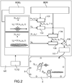
- FIG. 2 On the figure 2 , one can see a schematic representation of the method for generating signals to actuators of a touchscreen interface according to the invention.
- a schematic example of a touchscreen interface is shown, it implements 7 actuators.
- control unit simultaneously generates lubrication zones a and b for two fingers D1 and D2.
- the control unit has an acoustic lubrication effects database BDEL with continuous functions representative of acoustic lubrication effects.
- the lubrication effect obtained for each of these functions is different.
- the lubrication effect is linked to the amplitude, that is to say to the envelope of the vibration.
- the lubricating effect only lasts a short time, because the pattern has changed or because the finger moves and there is no longer any need to lubricate.
- the lubrication is maintained.
- each focal point is determined by its coordinates in the frame (x, y) designated (xa, ya) and (xb, yb).
- the presence of the finger is detected, for example by detecting the contact of the finger or fingers with the surface, so as to generate lubrication only in the presence of fingers.
- the signal to be sent to each actuator is determined.
- a search is made in the database BDRI for the impulse responses returned, the impulse response returned to point a. Either the response exists, because it has been determined beforehand, or it is determined by spatial interpolation as has been explained above (step 100). This response is designated hq (xa, ya, T-t).
- Each impulse response is then convolved to the continuous lubrication function Ua (step 102).
- step 104 the returned impulse response is convolved to the continuous lubrication function Ub.
- the convolution of the waveform Ua with a returned impulse response corresponds to a filtering of this waveform so that one obtains, after propagation in the medium, a displacement conforming to this waveform at the desired point.
- a signal corresponding to the sum of the signals calculated for each point (step 108) is sent to an actuator. This set of operations is carried out simultaneously for all the actuators on the surface.
- a signal amplification step 110 takes place.
- each actuator receives a continuous signal and applies a continuous force to the surface, this results in a continuous displacement at the focusing points a and b.
- the continuous function used for convolution can vary, so different continuous functions can be associated with the same area and one of them is selected for convolution based on parameters such as time, a display on the screen, an operator action ...
- a new continuous function can be established by combining at least two functions of the database.
- the control unit uses the information about the surface displacement to generate the signals to the actuators.
- the control unit takes into account the information on the movement of the surface and detects the movement of the finger to generate the signals to the actuators.
- the maximum frequency of each continuous function is such that it prevents resonance of the surface.
- different lubrications can be generated in different areas of the surface.
- the continuous function is typically a sinusoid of ultrasonic frequency, called the carrier frequency, amplitude modulated by a function whose frequency is within the tactile sensitivity band, ie preferably less than ⁇ 1 kHz.
- the carrier frequency is ideally in the ultrasonic range, preferably greater than 20 kHz and can reach up to several tens, or even several hundreds of kHz.
- the frequency of the continuous function does not correspond to a resonant frequency of the surface.
- the continuous function representative of the desired lubrication can alternatively be a square or sawtooth function, or even a random function.
- the high half-period of a square function applies a lubricating effect to the finger in contact with the surface, which decreases the friction.
- lubrication is lower.
- no lubrication is generated, the natural friction of the surface material is applied to the finger. The finger which moves on the surface then undergoes two very distinct frictions
- the convolution to the function Ua generates a signal to the actuator or actuators to generate at the point of focus a displacement of variable amplitude over time.
- the level of lubrication is then modulated over time.
- M (t) can be a continuous function making it possible, by modulating the level of lubrication during the movement of the finger from the surface, to simulate a texture. Indeed, by choosing the type of modulation, you can simulate any type of texture. For example, one can simulate a rough surface or a polished surface.
- the actuator or actuators are advantageously arranged at the level of the edges of the surface so as not to obstruct the visibility of the screen. If the surface is not transparent, the actuator (s) could be placed anywhere on the surface.
- the tactile stimulation interface according to the present invention has the advantage of being able, on the one hand, to restore a texture as has been described above, and on the other hand to simulate a relief, a confirmation click or a stiffness. local using the actuators and the returned impulse response database.
- the interface according to the present invention can be implemented, for example, in touch tablets in screens, in dashboards, in multifunction touch telephones.
- the interface according to the present invention can also be implemented in the field of micromanipulation, optics, biology, etc.
Landscapes
- Engineering & Computer Science (AREA)
- General Engineering & Computer Science (AREA)
- Computer Networks & Wireless Communication (AREA)
- Signal Processing (AREA)
- Theoretical Computer Science (AREA)
- Mechanical Engineering (AREA)
- Human Computer Interaction (AREA)
- Physics & Mathematics (AREA)
- General Physics & Mathematics (AREA)
- User Interface Of Digital Computer (AREA)
- Electrophonic Musical Instruments (AREA)
Description
La présente invention se rapporte à une interface à retournement temporel apte à générer une lubrification acoustique, pouvant être notamment mise en œuvre dans une interface tactile, par exemple pour simuler un effet de texture. L'interface selon l'invention peut également être mise en œuvre dans le cadre de la micromanipulation, de l'optique, de la biologie,...The present invention relates to a time reversal interface capable of generating acoustic lubrication, which can in particular be implemented in a touch interface, for example to simulate a texture effect. The interface according to the invention can also be implemented in the context of micromanipulation, optics, biology, etc.
Les interfaces de simulation tactile sont utilisées par exemple dans le domaine des interfaces homme-machines. Elles peuvent également être utilisées dans les domaines de l'optique, de l'acoustique, de la chimie, et de la fabrication automatisée... Une interface de stimulation tactile peut par exemple être mise en œuvre dans des smartphones, écrans, tableau de bords, tablettes...The tactile simulation interfaces are used for example in the field of man-machine interfaces. They can also be used in the fields of optics, acoustics, chemistry, and automated manufacturing ... A tactile stimulation interface can for example be implemented in smartphones, screens, switchboards. edges, shelves ...
Une interface tactile est par exemple apte à restituer une information tactile, telle qu'une texture, un relief, une rugosité variable dans le temps et/ou l'espace, une illusion d'appuyer sur un matériau souple, de presser une touche, en fonction des informations présentes sur l'écran et/ou de l'opération effectuée par l'utilisateur.A tactile interface is for example capable of reproducing tactile information, such as a texture, a relief, a roughness varying in time and / or space, an illusion of pressing on a flexible material, of pressing a key, depending on the information present on the screen and / or the operation performed by the user.
On cherche en particulier à restituer la sensation d'une texture lors de l'exploration tactile d'une surface.In particular, we seek to restore the sensation of a texture during the tactile exploration of a surface.
Pour cela, on génère des vibrations ultrasonores dans une plaque ; en corrélant l'amplitude des vibrations au mouvement d'un doigt à la surface de la plaque, l'utilisateur a l'illusion d'une surface texturée. Il s'agit en fait de faire varier le coefficient de friction entre le doigt et la plaque, on parle alors de lubrification acoustique ou de « squeeze film ». La modulation du niveau de lubrification en fonction de la position du doigt, plus particulièrement l'alternance de zones à fort puis faible coefficient de friction, est perçue par l'utilisateur comme une texture. La réduction de friction produit un effet perceptible uniquement lorsque le doigt est en mouvement sur la surface.For this, ultrasonic vibrations are generated in a plate; by correlating the amplitude of the vibrations with the movement of a finger on the surface of the plate, the user has the illusion of a textured surface. It is in fact a question of varying the coefficient of friction between the finger and the plate, one speaks then about acoustic lubrication or "squeeze film". The modulation of the level of lubrication as a function of the position of the finger, more particularly the alternation of areas with a high then a low coefficient of friction, is perceived by the user as a texture. The friction reduction produces a noticeable effect only when the finger is moving on the surface.
Une telle technique est par exemple décrite dans le document
Afin de produire ces vibrations, une interface de l'état de la technique met en œuvre un réseau d'actionneurs, par exemple piézoélectriques ou électrostatiques, qui appliquent un mouvement à la surface de l'interface. Or, afin de produire un effet perceptible et simuler une réduction de friction, l'amplitude des vibrations produites est au moins de l'ordre du micromètre. Pour atteindre une telle amplitude, la surface de la plaque est mise en résonance en pilotant les actionneurs avec un signal harmonique de fréquence correspondant à une fréquence propre de la surface. Cette excitation, identique pour tous les actionneurs, a plusieurs inconvénients :
- D'une part, toute la surface est mise en vibration par les actionneurs. Il en résulte que tous les doigts en contact avec la surface perçoivent sensiblement le même stimulus, en effet cette sensation dépend de la position des doigts par rapport aux nœuds et ventres de vibrations, mais cette position n'est pas contrôlable. Il n'est donc pas possible, dans le cas où au moins deux doigts sont en contact avec la surface, d'ajuster l'amplitude de vibration au niveau de chaque doigt et donc de stimuler une texture différente pour chaque doigt.
- D'autre part, pour que les ondes produites dans la plaque par les différents actionneurs s'additionnent constructivement, les actionneurs sont placés en des points de la surface vibrant en phase. A une fréquence propre de la plaque, les contributions de deux actionneurs excités avec le même signal mais situés en des points vibrant en opposition de phase interfèrent de façon destructive, résultant en une excitation nulle. Le pilotage avec un signal unique impose donc des contraintes sur l'emplacement des actionneurs selon le mode propre excité.
- De plus, les modes propres d'une plaque présentent une alternance de ventres de vibration ayant une amplitude maximale, et de nœuds ayant une amplitude nulle. L'excitation modale produit donc un champ de vibration et donc une réduction du coefficient de friction non homogène sur la surface.
- Par ailleurs, pour obtenir une forte amplitude à une fréquence propre, l'atténuation des vibrations dans la surface doit être faible. Or cette faible atténuation implique un temps de réponse du système long, ce qui limite la finesse des textures tactiles pouvant être restituées.
- On the one hand, the entire surface is put into vibration by the actuators. It follows that all the fingers in contact with the surface perceive substantially the same stimulus, in fact this sensation depends on the position of the fingers with respect to the nodes and bellies of vibrations, but this position is not controllable. It is therefore not possible, in the case where at least two fingers are in contact with the surface, to adjust the amplitude of vibration at the level of each finger and therefore to stimulate a different texture for each finger.
- On the other hand, so that the waves produced in the plate by the different actuators add up constructively, the actuators are placed at points of the surface vibrating in phase. At a natural frequency of the plate, the contributions of two actuators excited with the same signal but located at points vibrating in phase opposition interfere destructively, resulting in zero excitation. Control with a single signal therefore imposes constraints on the location of the actuators according to the energized eigenmode.
- Moreover, the eigen modes of a plate present an alternation of bellies of vibration having a maximum amplitude, and of nodes having a zero amplitude. The modal excitation therefore produces a vibration field and therefore a reduction in the non-homogeneous coefficient of friction on the surface.
- Furthermore, to obtain a high amplitude at a natural frequency, the attenuation of vibrations in the surface must be low. However, this low attenuation implies a long system response time, which limits the fineness of the tactile textures that can be restored.
Par ailleurs, il existe des interfaces tactiles utilisant le procédé de retournement temporel, par exemple décrites dans le document
Ce document propose de répéter le procédé de focalisation par retournement temporel afin de former un train d'impulsions de déplacement afin d'offrir une stimulation intensifiée. Mais cette répétition d'impulsions ne permet pas d'obtenir un effet de lubrification acoustique notable.This document proposes to repeat the method of focusing by time reversal in order to form a train of displacement pulses in order to offer an intensified stimulation. However, this repetition of pulses does not make it possible to obtain a noticeable acoustic lubricating effect.
Le document
C'est par conséquent un but de la présente invention d'offrir une interface apte à générer un effet de lubrification acoustique notable, notamment une interface de stimulation tactile permettant par exemple une simulation d'une texture.It is consequently an aim of the present invention to offer an interface capable of generating a significant acoustic lubrication effect, in particular a tactile stimulation interface allowing for example a simulation of a texture.
Le but énoncé ci-dessus est atteint par les revendications attachées à cette description, qui définissent la présente invention.The object stated above is achieved by the claims attached to this description, which define the present invention.
On propose une interface comportant une surface, au moins un actionneur apte à appliquer un effort sur la surface, et des moyens de commande dudit actionneur mettant en œuvre un procédé de retournement temporel associé à une convolution par une fonction continue représentative de l'effet de lubrification acoustique souhaité.An interface is proposed comprising a surface, at least one actuator capable of applying a force to the surface, and means for controlling said actuator implementing a time reversal method associated with a convolution by a continuous function representative of the effect of desired acoustic lubrication.
La nature discontinue des impulsions générées au point de focalisation par le procédé de retournement temporel est transformée en déplacement continu en convoluant les réponses impulsionnelles retournées du procédé de retournement temporel en un point de focalisation par une fonction continue. Le déplacement continu au point de focalisation simule de manière localisée l'effet souhaité. Par exemple, la fonction représentative peut être une fonction sinusoïdale, une fonction carrée, en dent de scie, voire une fonction aléatoire.The discontinuous nature of the pulses generated at the focus point by the time reversal process is transformed into continuous displacement by convolving the impulse responses returned from the time reversal process into a focus point by a continuous function. Continuous movement at the point of focus locally simulates the desired effect. For example, the representative function can be a sinusoidal function, a square function, a sawtooth function, or even a random function.
La convolution par une fonction continue réduit l'amplitude au point de focalisation, si celle-ci est insuffisante pour être perçue, elle est suffisante pour générer un effet de lubrification.Convolution by a continuous function reduces the amplitude at the focal point, if this is insufficient to be perceived, it is sufficient to generate a lubricating effect.
En d'autres termes, les inventeurs ont réussi à générer un effet de lubrification acoustique en mettant en œuvre un procédé de retournement temporel.In other words, the inventors have succeeded in generating an acoustic lubrication effect by implementing a time reversal process.
Dans le cas d'une interface tactile, en mettant en œuvre un procédé de retournement temporel, la stimulation est localisée, il est alors possible de générer au niveau de plusieurs doigts des niveaux de friction différents.In the case of a tactile interface, by implementing a time reversal method, the stimulation is localized, it is then possible to generate different levels of friction at the level of several fingers.
De plus, les impulsions produites par ce procédé sont de fortes amplitudes, par exemple de l'ordre de 1 µm. Il n'est alors pas nécessaire d'utiliser une surface présentant une faible atténuation. Les niveaux de lubrification peuvent alors varier plus rapidement, les textures simulées sont alors plus fines.In addition, the pulses produced by this method are of high amplitudes, for example of the order of 1 μm. It is then not necessary to use a surface having a low attenuation. The lubrication levels can then vary more quickly, the simulated textures are then finer.
De manière très avantageuse, les actionneurs mis en œuvre dans une interface appliquant un procédé de retournement temporel, peuvent être disposés avec une grande liberté. De préférence ils sont disposés au niveau des bords de la surface, et ne gênent alors pas la visibilité d'un écran qui serait disposé sous la surface.Very advantageously, the actuators implemented in an interface applying a time reversal method, can be arranged with great freedom. Preferably, they are arranged at the level of the edges of the surface, and then do not interfere with the visibility of a screen which would be placed under the surface.
Dans un mode avantageux, le niveau de lubrification générée est modulé, ainsi le niveau de friction varie au cours du déplacement du doigt, par exemple pour confirmer à l'utilisateur qu'il suit effectivement le bon chemin sur la surface, ou pour simuler une texture.In an advantageous mode, the level of lubrication generated is modulated, thus the level of friction varies during the movement of the finger, for example to confirm to the user that he is indeed following the correct path on the surface, or to simulate a texture.
La présente invention a alors pour objet une interface comportant une surface, au moins un actionneur destiné à appliquer un effort sur ladite surface, et des moyens de commande dudit au moins un actionneur, lesdits moyens de commande étant destinés à envoyer à l'actionneur des signaux correspondant aux efforts à appliquer à ladite surface, lesdits efforts étant déterminés par un procédé de retournement temporel, dans laquelle les moyens de commande comportent une base de données de réponses impulsionnelles retournées, une base de données des effets de lubrification acoustique comportant au moins une fonction continue représentative d'un effet de lubrification acoustique, et des moyens de convolution d'une réponse impulsionnelle retournée à une fonction continue, et dans laquelle les moyens de commande sont configurés, pour produire une lubrification acoustique dans au moins une zone donnée de la surface, à générer au moins un signal formé à partir d'une convolution d'une réponse impulsionnelle retournée déterminée à partir de la base de données de réponses impulsionnelles retournées à une fonction continue de la base de données des effets de lubrification acoustique.The subject of the present invention is therefore an interface comprising a surface, at least one actuator intended to apply a force to said surface, and control means of said at least one actuator, said control means being intended to send to the actuator signals corresponding to the forces to be applied to said surface, said forces being determined by a time reversal process, in which the control means comprise a database of returned impulse responses, a database of acoustic lubrication effects comprising at least one continuous function representative of an effect lubrication system, and means for convolving an impulse response returned to a continuous function, and in which the control means are configured, to produce acoustic lubrication in at least a given area of the surface, to generate at least one signal formed from a convolution of a returned impulse response determined from the database of returned impulse responses to a continuous function of the database of acoustic lubrication effects.
Dans un exemple avantageux, les moyens de commande sont configurés pour commander ledit au moins un actionneur de sorte que des lubrifications acoustiques différentes soient générer dans au moins zones de la surface simultanément.In an advantageous example, the control means are configured to control said at least one actuator so that different acoustic lubrications are generated in at least areas of the surface simultaneously.
Par exemple, la base de données des effets de lubrification acoustique comporte au moins une fonction sinusoïdale.For example, the acoustic lubrication effects database has at least one sinusoidal function.
Avantageusement, l'interface comporte des moyens de détection du contact d'au moins un objet avec la surface et des moyens de suivi du déplacement relatif dudit objet et de la surface. Les moyens de détection du contact d'au moins un objet avec la surface et/ou les moyens de suivi du déplacement relatif dudit objet et de la surface peuvent être de type capacitif, de sorte à ne produire une lubrification acoustique qu'au niveau du contact entre l'objet et la surface.Advantageously, the interface comprises means for detecting the contact of at least one object with the surface and means for monitoring the relative displacement of said object and of the surface. The means for detecting the contact of at least one object with the surface and / or the means for monitoring the relative movement of said object and the surface may be of the capacitive type, so as to produce acoustic lubrication only at the level of the surface. contact between object and surface.
Selon une caractéristique additionnelle, l'interface peut comporter des moyens de détection de la force de contact entre au moins un objet et la surface, et les moyens de commande peuvent être configurés pour moduler l'effet de lubrification acoustique en fonction de ladite force de contact.According to an additional characteristic, the interface can comprise means for detecting the force of contact between at least one object and the surface, and the control means can be configured to modulate the effect of acoustic lubrication as a function of said force of contact. contact.
L'interface de stimulation tactile peut avantageusement comporter plusieurs actionneurs.The tactile stimulation interface can advantageously include several actuators.
La surface est par exemple portée par une plaque, le ou les actionneurs étant situés en contact avec la plaque au niveau d'au moins un bord de celle-ci. La plaque est avantageusement transparente.The surface is for example carried by a plate, the actuator (s) being located in contact with the plate at the level of at least one edge thereof. The plate is advantageously transparent.
La présente invention a également pour objet une interface de stimulation tactile comportant une interface selon l'invention, la surface étant destinée à être explorée tactilement par au moins un organe d'un utilisateur.A subject of the present invention is also a tactile stimulation interface comprising an interface according to the invention, the surface being intended to be explored tactile by at least one organ of a user.
Les moyens de commande sont avantageusement configurés pour moduler l'effet de lubrification acoustique en fonction du déplacement relatif dudit organe et de ladite surface de sorte à simuler un effet de texture.The control means are advantageously configured to modulate the effect of acoustic lubrication as a function of the relative displacement of said member and of said surface so as to simulate a texture effect.
Les moyens de commande peuvent également être avantageusement configurés, à partir de la base de données de réponses impulsionnelles retournées, pour envoyer à l'actionneur des signaux correspondant à des efforts à appliquer à ladite surface de sorte à stimuler tactilement ledit organe selon un motif tactile donné.The control means can also be advantageously configured, from the database of returned impulse responses, to send to the actuator signals corresponding to the forces to be applied to said surface so as to stimulate the said organ in a tactile manner. given.
Selon une caractéristique additionnelle, l'interface de stimulation tactile peut comporter des moyens pour au moins réduire l'adhérence dudit organe à la surface due à une accumulation d'humidité.According to an additional characteristic, the tactile stimulation interface can comprise means for at least reducing the adhesion of said organ to the surface due to an accumulation of humidity.
La présente invention a également pour objet un procédé de commande d'une interface selon l'invention, de sorte générer au moins un effet de lubrification acoustique dans au moins une première zone donnée, comportant les étapes :
- a) détermination d'une réponse impulsionnelle retournée,
- b) sélection d'une fonction continue en fonction de l'effet de lubrification acoustique souhaité,
- c) convolution de ladite réponse impulsionnelle retournée à ladite fonction continue,
- d) génération d'un signal sur la base du résultat de ladite convolution et envoi dudit signal audit au moins un actionneur et génération d'impulsions.
- a) determination of a returned impulse response,
- b) selection of a continuous function according to the desired acoustic lubrication effect,
- c) convolution of said impulse response returned to said continuous function,
- d) generating a signal based on the result of said convolution and sending said signal to said at least one actuator and generating pulses.
Les étapes a) à d) sont avantageusement réalisées simultanément pour la première zone et pour au moins une deuxième zone distincte de la première zone, et lors de l'étape d) le signal envoyé audit actionneur est avantageusement la somme du signal généré pour la première zone et le signal généré pour la deuxième zone.Steps a) to d) are advantageously carried out simultaneously for the first zone and for at least a second zone distinct from the first zone, and during step d) the signal sent to said actuator is advantageously the sum of the signal generated for the first zone. first zone and the signal generated for the second zone.
Dans un exemple de réalisation, lors de l'étape a), la réponse impulsionnelle retournée est choisie dans une base de données.In an exemplary embodiment, during step a), the returned impulse response is chosen from a database.
Dans un autre exemple de réalisation, lors de l'étape a), la réponse impulsionnelle retournée est déterminée par interpolation entre au moins deux réponses impulsionnelles retournées choisies dans une base de données.In another exemplary embodiment, during step a), the returned impulse response is determined by interpolation between at least two returned impulse responses chosen from a database.
Dans le cas où l'interface est une interface de stimulation tactile, le procédé peut comporter une étape préalable à l'étape a) de détection d'une zone contact entre l'organe et le doigt, et, lors de l'étape a), la réponse impulsionnelle retournée peut être déterminée pour ladite zone de contact.In the case where the interface is a tactile stimulation interface, the method may include a step prior to step a) of detecting a contact zone between the organ and the finger, and, during step a ), the returned impulse response can be determined for said contact area.
Le procédé de commande peut comporter une étape, en amont de l'étape d), de modulation de l'effet de lubrification acoustique en fonction du déplacement relatif d'un organe en contact avec la surface.The control method may include a step, upstream of step d), of modulating the effect of acoustic lubrication as a function of the relative displacement of a member in contact with the surface.
Avantageusement, la force exercée par l'organe sur la surface est mesurée et est prise en compte pour moduler l'effet de lubrification acoustique.Advantageously, the force exerted by the member on the surface is measured and is taken into account in order to modulate the effect of acoustic lubrication.
La présente invention sera mieux comprise sur la base de la description qui va suivre et des dessins en annexe sur lesquels:
- la
figure 1A est une vue de dessus d'un exemple de réalisation d'une interface de stimulation tactile, - la
figure 1B est une vue en coupe de lafigure 1A selon le plan A-A, - la
figure 1C est une vue de détail de lafigure 1B au niveau d'un actionneur, - la
figure 2 est une représentation schématique d'un organigramme du procédé de génération de signaux de commande des actionneurs d'une interface tactile selon l'invention, - les
figures 3A à 3C sont des exemples de fonctions continues représentatives de la simulation souhaitée.
- the
figure 1A is a top view of an exemplary embodiment of a tactile stimulation interface, - the
figure 1B is a sectional view of thefigure 1A according to plan AA, - the
figure 1C is a detail view of thefigure 1B at the level of an actuator, - the
figure 2 is a schematic representation of a flowchart of the method for generating control signals for the actuators of a touchscreen interface according to the invention, - the
figures 3A to 3C are examples of continuous functions representative of the desired simulation.
Dans la description qui va suivre, l'invention sera décrite principalement dans l'application à une interface de stimulation tactile. Mais l'invention s'applique à une interface destinée par exemple à manipuler des objets.In the description which follows, the invention will be described mainly in the application to a tactile stimulation interface. But the invention applies to an interface intended for example to handle objects.
Dans la description qui va suivre, on considérera qu'une surface tactile est destinée à être touchée par la pulpe d'un doigt ou de plusieurs doigts à des fins de simplicité. Mais la surface de l'interface selon l'invention est apte à appliquer une stimulation à toute partie du corps de l'opérateur sensible au sens du toucher.In the description which follows, it will be considered that a tactile surface is intended to be touched by the pulp of one finger or of several fingers for the sake of simplicity. However, the surface of the interface according to the invention is capable of applying stimulation to any part of the operator's body sensitive to the sense of touch.
On entend par « point de focalisation », le point où les ondes acoustiques sont focalisées et qui est le siège d'un déplacement de grande amplitude de la surface et par « zone de stimulation » la zone où l'on souhaite générer une lubrification ultrasonique.The term “focal point” is understood to mean the point where the acoustic waves are focused and which is the site of a large amplitude displacement of the surface and by “stimulation zone” the zone where it is desired to generate ultrasonic lubrication. .
L'effet de lubrification acoustique requiert un déplacement entre les doigts et la surface. Dans la description qui va suivre, c'est le doigt qui est déplacé par rapport à la surface. Un système dans lequel ce serait la surface qui serait déplacée par rapport au doigt fixe ou toute autre partie du corps, ou dans lequel la surface et le doigt ou toute autre partie du corps seraient mobiles, entre dans le cadre de la présente invention.The acoustic lubricating effect requires movement between the fingers and the surface. In the description which follows, it is the finger which is moved relative to the surface. A system in which the surface is displaced relative to the fixed finger or any other part of the body, or in which the surface and the finger or any other part of the body are movable, falls within the scope of the present invention.
Sur les
L'interface tactile I1 comporte un cadre 2, un élément 3 muni d'une surface 4 maintenue sur le cadre 2, et sur laquelle par exemple un ou des doigts peuvent venir en contact, et des actionneurs 6 fixés sur l'élément 3 et aptes à appliquer une contrainte mécanique à la surface 4, la contrainte étant orientée transversalement par rapport à la surface. La partie suspendue de la surface 4 forme une surface destinée à être explorée tactilement. Dans le cas d'une interface de manipulation d'objet, la surface 4 est destinée à supporter un ou des objets.The tactile interface I1 comprises a
L'élément 3 est, dans l'exemple représenté, sous forme d'une plaque.
Le cadre forme un support rigide pour la plaque 3. De manière avantageuse, un matériau amortissant 9, est interposé entre la plaque 3 et le support rigide. Avantageusement le matériau amortissant 9 est une mousse adhésive, qui en plus d'atténuer les vibrations dans la plaque 3 et maintient la plaque 3 sur le cadre.The frame forms a rigid support for the
Les actionneurs 6 sont fixés, par exemple par collage sur la face 11 de l'élément 3 opposée à la surface 4. Dans l'exemple représenté, les actionneurs sont montés le long du bord de l'élément 3. Dans un autre exemple, les actionneurs peuvent être disposés en tout point de l'élément 3. En outre les actionneurs pourraient être sur la surface tactile 4.The
La surface 4 est destinée à être le siège d'ondes de flexion ou ondes transversales générées par les contraintes appliquées par les actionneurs. Selon l'invention, les ondes de flexion sont focalisées de sorte à produire une stimulation tactile au point de focalisation.The
L'élément portant la surface 4 est par exemple un substrat rigide transparent ou non. Le substrat peut être plan ou incurvé. Le substrat peut comporter un ou plusieurs matériaux. En outre il peut avoir une épaisseur comprise entre 0,1 mm et 5 mm.The element carrying the
Par exemple, l'élément portant la surface 4 est par exemple une plaque transparente en verre, en polycarbonate, en PMMA, ou non-transparente en métal, en céramique, plastique ou autre.For example, the element carrying the
La mise en œuvre d'un substrat transparent permet par exemple d'adapter l'interface à un écran, par exemple à l'écran d'une tablette tactile.The use of a transparent substrate makes it possible for example to adapt the interface to a screen, for example to the screen of a touchscreen tablet.
Dans l'exemple représenté, les actionneurs sont des actionneurs piézoélectriques. Ils comportent un matériau piézoélectrique et deux électrodes de part et d'autre du matériau piézoélectrique permettant de lui appliquer une différence de potentiel. L'application d'une différence de potentiel aux bornes de l'actionneur piézoélectrique produit à la surface de la plaque des efforts tangents à la plaque. Cet effort courbe la surface de la plaque. Il en résulte un déplacement dans la direction perpendiculaire au plan de la surface.In the example shown, the actuators are piezoelectric actuators. They comprise a piezoelectric material and two electrodes on either side of the piezoelectric material allowing a potential difference to be applied to it. The application of a potential difference across the piezoelectric actuator produces on the surface of the plate forces tangent to the plate. This force curves the surface of the plate. This results in a displacement in the direction perpendicular to the plane of the surface.
En variante, les actionneurs peuvent être électromagnétiques. Dans ce cas un effort perpendiculaire au plan de la surface est produit par l'action d'un champ électromagnétique sur un aimant. L'aimant ou la bobine est solidaires de la surface.Alternatively, the actuators can be electromagnetic. In this case, a force perpendicular to the plane of the surface is produced by the action of an electromagnetic field on a magnet. The magnet or coil is integral with the surface.
Dans l'exemple représenté, l'interface comporte trente-deux actionneurs disposés le long des bords de la surface 4, cependant ce nombre n'est pas limitatif. On peut par exemple prévoir 1, 10 ou plusieurs dizaines d'actionneurs, par exemple 40, répartis sur le support.In the example shown, the interface comprises thirty-two actuators arranged along the edges of the
L'interface comporte également une unité de commande destinée à générer des signaux aux actionneurs afin qu'ils appliquent des efforts à la surface de sorte à générer des ondes de flexion en un point de focalisation donné.The interface also includes a control unit intended to generate signals to the actuators so that they apply forces to the surface so as to generate bending waves at a given focal point.
Les efforts appliqués par les actionneurs 6 sur la surface 4 sont calculés par un procédé de retournement temporel, ce qui permet aux actionneurs de générer des ondes interférant de façon constructives en un ou plusieurs point(s) donnés de la surface et à un instant souhaité. L'utilisateur ressent, non pas les ondes se propageant dans la plaque mais l'impulsion produite au(x) point(s) et à l'instant souhaité due à l'interférence constructive. Le gain des actionneurs est réglé de sorte que l'amplitude partout ailleurs, en dehors du point de focalisation, soit telle qu'on ne perçoive pas la vibration. Le contraste, qui désigne le rapport de l'amplitude au point de focalisation par l'amplitude quadratique moyenne en tout autre point est donc une grandeur critique qu'il convient de maximiser pour produire une stimulation clairement perçue au point de focalisation sans créer de stimulus en un autre point. Dans l'exemple présenté, le contraste pour une focalisation unique vaut C=43 et l'amplitude au point de focalisation atteint a=14 µm.The forces applied by the
La mousse adhésive présente dans l'exemple sert, d'une part à maintenir la plaque sur son support et d'autre part à atténuer les vibrations de celle-ci. Cette atténuation permet de réduire la constante d'atténuation τ et donc de diminuer la période de répétition de focalisation Tr sans altérer le contraste de focalisation répétée Ĉ, conformément à l'expression donnée plus bas. Cette atténuation peut être également ajustée par un choix approprié de matériau pour la plaque ou par l'ajout d'un film à sa surface.The adhesive foam present in the example serves, on the one hand, to hold the plate on its support and, on the other hand, to attenuate the vibrations thereof. This attenuation makes it possible to reduce the attenuation constant τ and therefore to reduce the focusing repetition period T r without altering the repeated focusing contrast Ĉ , in accordance with the expression given below. This attenuation can also be adjusted by an appropriate choice of material for the plate or by adding a film to its surface.
De manière avantageuse, la surface est telle qu'elle limite, voire empêche l'adhérence de la peau à la surface due à l'accumulation d'humidité. Par exemple, on peut envisager que la plaque portant la surface soit en un matériau poreux, par exemple en verre poreux, ou avec un état de surface limitant la surface de contact effective avec le doigt. Par exemple la surface subit un traitement hydrophobe ou est recouverte d'un film hydrophobe. L'épaisseur du film, par exemple entre quelques dizaines et quelques centaines de µm, est telle que le film n'a pas ou peu d'effet sur la transmission de la stimulation de la surface au doigt. Le film est par exemple collé ou déposé sur la surface.Advantageously, the surface is such that it limits or even prevents the adhesion of the skin to the surface due to the accumulation of humidity. For example, it is conceivable that the plate bearing the surface is made of a porous material, for example porous glass, or with a surface condition limiting the effective contact surface with the finger. For example, the surface undergoes a hydrophobic treatment or is covered with a hydrophobic film. The thickness of the film, for example between a few tens and a few hundred μm, is such that the film has little or no effect on the transmission of the stimulation from the surface to the finger. The film is for example glued or deposited on the surface.
L'interface comporte également une unité de commande UC destinée à générer des signaux aux actionneurs afin qu'ils appliquent des efforts à la surface 4, afin de faire varier en un ou plusieurs points de focalisation le niveau de friction, par exemple en vue de reproduire ou simuler une texture, qui peut être une rugosité ou une texture plus douce.The interface also comprises a control unit UC intended to generate signals to the actuators so that they apply forces to the
Pour cela, l'unité de commande met en œuvre un procédé de retournement temporel déterminant des réponses impulsionnelles retournées afin de générer un déplacement d'un point donné de la surface, appelé point de focalisation et une convolution de ces réponses impulsionnelles retournées par un signal continu.To do this, the control unit implements a time reversal method determining the impulse responses returned in order to generate a displacement of a given point on the surface, called a focal point, and a convolution of these impulse responses returned by a signal. continued.
L'interface comporte également une unité de commande UC destinée à générer des signaux aux actionneurs afin qu'ils appliquent des efforts à la surface 4 de sorte à générer des ondes de flexion en un point de focalisation donné.The interface also comprises a control unit UC intended to generate signals to the actuators so that they apply forces to the
Les efforts appliqués par les actionneurs 6 sur la surface 4 sont calculés par un procédé de retournement temporel, ce qui permet aux actionneurs de générer des ondes progressives constructives en un ou plusieurs point(s) donnés de la surface et à un instant souhaité. L'utilisateur ressent, non pas le passage d'une onde progressive, mais l'amplitude atteinte au(x) point(s) et à l'instant souhaité due à l'interférence constructive. Le gain des actionneurs est réglé de sorte que l'amplitude partout ailleurs, en dehors du point de focalisation, soit inférieure au seuil de sensibilité tactile. Le seuil de sensibilité tactile désigne la plus faible amplitude vibratoire perceptible. Il dépend des conditions de contact et de la fréquence mais se situe autour de 10 µm. On peut donc amplifier ou atténuer le déplacement de la surface de sorte que seule l'amplitude atteinte aux points de focalisation soit supérieure à ce seuil et donc soit perceptible. La surface semble ainsi immobile excepté aux points de focalisation.The forces applied by the
L'interface comporte avantageusement des moyens de détection 10 de la présence des doigts de l'utilisateur sur l'interface afin de générer une lubrification acoustique aux zones de contact du ou des doigts avec la surface. La lubrification acoustique peut alors n'être générée qu'au cours d'exploration par les doigts. La consommation électrique de l'interface peut alors être réduite ce qui est particulièrement intéressant dans le cas d'interfaces de stimulation tactile appliquées à des appareils portables. Il peut s'agir par exemple de moyens de type capacitif ou optique. L'interface comporte également des moyens de suivi de la position du ou des doigts 12.The interface advantageously comprises means 10 for detecting the presence of the user's fingers on the interface in order to generate acoustic lubrication at the areas of contact of the finger or fingers with the surface. The acoustic lubrication can then only be generated during exploration by the fingers. The electrical consumption of the interface can then be reduced, which is particularly advantageous in the case of tactile stimulation interfaces applied to portable devices. It may be, for example, capacitive or optical type means. The interface also includes means for monitoring the position of the finger or fingers 12.
Dans le cas d'une détection capacitive, la plaque portant la surface formant une des plaques d'un condensateur à capacité variable et la pulpe du doigt forme l'autre plaque. Il est en outre possible de déterminer la direction et le sens dans lesquels l'utilisateur a l'intention de déplacer son doigt sur la surface, ce qui permet d'éviter un effet retard dans la simulation. Pour cela, on peut mettre en œuvre des capteurs de force pour mesurer les efforts tangentiels produits par le glissement du doigt sur la surface. Ces efforts sont produits par la friction et sont de direction opposée au mouvement. Les efforts exercés par le doigt sur la plaque sont transmis de la plaque à son support. On peut alors disposer de tels capteurs de force à l'interface entre la plaque et son support.In the case of capacitive detection, the plate carrying the surface forming one of the plates of a variable capacitance capacitor and the pulp of the finger forms the other plate. It is furthermore possible to determine the direction and the direction in which the user intends to move his finger on the surface, which makes it possible to avoid a delay effect in the simulation. For this, force sensors can be used to measure the tangential forces produced by the sliding of the finger on the surface. These forces are produced by friction and are in the opposite direction to the movement. The forces exerted by the finger on the plate are transmitted from the plate to its support. It is then possible to have such force sensors at the interface between the plate and its support.
Nous allons décrire brièvement le principe du procédé de retournement temporel.We will briefly describe the principle of the time reversal process.
Le principe du retournement temporel des ondes repose sur l'invariance de l'équation de propagation d'ondes par renversement du temps et sur le principe de réciprocité.The principle of the time reversal of waves is based on the invariance of the wave propagation equation by time reversal and on the principle of reciprocity.
Soit h(xa |xq,ya |yq,t) le déplacement hors plan de la surface enregistré au cours du temps t en un point de coordonnées (xa,ya ) après qu'un signal impulsionnel a été émis par un actionneur en (xq,yq ). On appelle h(xa |xq,ya |yq,t) la réponse impulsionnelle entre les points a et q.Let h ( x a | x q , y a | y q , t ) be the out-of-plane displacement of the surface recorded during time t at a point of coordinates ( x a , y a ) after a pulse signal has been emitted by an actuator at ( x q , y q ). We call h ( x a | x q , y a | y q , t ) the impulse response between points a and q .
En considérant que la réponse du système plaque et actionneur est linéaire, si l'actionneur situé en q émet non plus une impulsion mais un signal sq (t), le déplacement au point a est alors donné par: u(xa,ya,t)= h(xa |xq,ya |yq,t) ⊗ sq (t) avec ⊗ l'opérateur de convolution.Considering that the response of the plate and actuator system is linear, if the actuator located at q no longer emits an impulse but a signal s q ( t ) , the displacement at point a is then given by: u ( x a , y a , t ) = h ( x a | x q , y a | y q , t ) ⊗ s q ( t ) with ⊗ the convolution operator.
Ainsi, si l'actionneur situé en q émet, non plus une impulsion mais la réponse impulsionnelle retournée temporellement depuis l'instant T jusqu'à l'instant initial t = 0, soit ![]()

![]()
Le déplacement est ainsi le résultat de l'intégrale du produit de deux fonctions qui ne sont a priori pas corrélées dont le résultat est donc de moyenne nulle. On a en un point b et un instant t quelconque un déplacement de moyenne nulle qui constitue une vibration de fond présente sur l'ensemble de la plaque. En revanche, à l'instant t = T correspondant à la fin de la phase d'émission par l'actionneur, on obtient au point a un déplacement : ![]()
![]()
On intègre cette fois une quantité strictement positive. Le résultat est un déplacement non nul de grande amplitude. Ce déplacement est obtenu uniquement au point a et à l'instant T, d'où la focalisation des ondes dans l'espace et dans le temps.This time we integrate a strictly positive quantity. The result is a large amplitude non-zero displacement. This displacement is obtained only at point a and at time T, hence the focusing of the waves in space and time.
Dans le cas où Q actionneurs sont utilisés, leurs contributions s'additionnent pour donner : 
Le contraste est défini comme le rapport entre le déplacement au point de focalisation au temps T et l'écart type de ce déplacement en un point quelconque b. Il est obtenu par la relation : 
Avec Q le nombre d'actionneurs, T la durée de la fenêtre de retournement, τ la constant de temps d'atténuation des vibrations dans la plaque et Tc le temps caractéristique de la plaque ou densité modale de la plaque en secondes, ou mode propre par Hz et B = fmax - fmin la bande passante, en hertz des signaux émis par les actionneurs.With Q the number of actuators, T the duration of the reversal window, τ the constant vibration attenuation time in the plate and T c the characteristic time of the plate or modal density of the plate in seconds, or mode clean by Hz and B = f max - f min the pass band, in hertz of the signals emitted by the actuators.
Dès lors que la focalisation est répétée dans le temps avec une période Tr, le contraste est affecté selon la relation : ![]()
![]()
Pour préserver le contraste, les focalisations successives sont répétées avec une période Tr ≥ τ. To preserve the contrast, the successive focalizations are repeated with a period T r ≥ τ.
La fréquence moyenne des signaux définie la résolution maximale atteignable par la relation : 
Avec Rs la résolution spatiale, ou largeur à mi-hauteur du point de focalisation, ![]()
![]()
Les réponses impulsionnelles hAnl(t) peuvent être obtenues, soit de façon expérimentale en enregistrant effectivement les réponses impulsionnelles, soit par simulation, soit de manière analytique lorsque la géométrie reste simple.The impulse responses h Anl (t) can be obtained, either experimentally by actually recording the impulse responses, or by simulation, or analytically when the geometry remains simple.
On réalise ensuite une base de données des réponses impulsionnelles retournées en différents points de la surface, cette base de données est utilisée pour générer les signaux envoyés aux actionneurs. Il peut s'agir de tous points de la surface ou selon un maillage très serré, afin d'offrir une grande résolution dans la stimulation. En variante et de manière particulièrement avantageuse, on réalise une base de données des réponses impulsionnelles en un nombre de points donnés de la surface, par exemple répartis sous la forme d'une grille ou sur un contour de la surface. On détermine ensuite les réponses impulsionnelles entre les points de la grille, par exemple par interpolation, ce qui permet ainsi de déterminer une réponse impulsionnelle en tout point de la surface, et de réduire le temps de réalisation de la base de données et sa taille. L'interpolation peut se faire suivant différentes méthodes, par exemple il peut s'agir d'une interpolation de Fourier, de la méthode « Compressed Sensing », les méthodes des solutions fondamentales, ou une méthode s'appuyant sur une forme variationnelle de l'équation de propagation.A database of the impulse responses returned at various points on the surface is then produced; this database is used to generate the signals sent to the actuators. It can be at all points of the surface or according to a very tight mesh, in order to offer a great resolution in the stimulation. As a variant and in a particularly advantageous manner, a database of the impulse responses is produced at a given number of points on the surface, for example distributed in the form of a grid or on an outline of the surface. The impulse responses between the points of the grid are then determined, for example by interpolation, which thus makes it possible to determine an impulse response at any point on the surface, and to reduce the production time of the database and its size. The interpolation can be done according to different methods, for example it can be a question of a Fourier interpolation, of the “Compressed Sensing” method, the methods of fundamental solutions, or a method based on a variational form of l 'propagation equation.
Sur la
Dans l'exemple représenté, l'unité de commande génère simultanément des zones de lubrification a et b pour deux doigts D1 et D2.In the example shown, the control unit simultaneously generates lubrication zones a and b for two fingers D1 and D2.
On souhaite générer une première lubrification dans la zone a et une deuxième lubrification dans la zone b.It is desired to generate a first lubrication in zone a and a second lubrication in zone b.
L'unité de commande comporte une base de données des effets de lubrification acoustique BDEL comportant des fonctions continues représentatives d'effets de lubrification acoustique.The control unit has an acoustic lubrication effects database BDEL with continuous functions representative of acoustic lubrication effects.
La première lubrification est représentée par la fonction continue Ua = U(xa, ya, t) qui est une fonction « sinus fenêtré » (« sine burst » en terminologie anglo-saxonne), et la deuxième lubrification est représentée par la fonction continue Ub = U(xb, yb, t) qui est une fonction sinusoïdale. L'effet de lubrification obtenu pour chacune de ces fonctions est différent.The first lubrication is represented by the continuous function Ua = U (xa, ya, t) which is a “window sine burst” function, and the second lubrication is represented by the continuous function Ub = U (xb, yb, t) which is a sinusoidal function. The lubrication effect obtained for each of these functions is different.
L'effet de lubrification est lié à l'amplitude, c'est à dire à l'enveloppe de la vibration. Dans le cas de la fonction Ua, l'effet de lubrification ne dure qu'un court instant, parce que le motif a changé ou parce que le doigt bouge et qu'il n'y a plus lieu de lubrifier. Dans le cas de la fonction Ub, la lubrification est maintenue.The lubrication effect is linked to the amplitude, that is to say to the envelope of the vibration. In the case of the Ua function, the lubricating effect only lasts a short time, because the pattern has changed or because the finger moves and there is no longer any need to lubricate. In the case of the Ub function, the lubrication is maintained.
L'emplacement de chaque point de focalisation est déterminé par ses coordonnées dans le repère (x, y) désignées (xa, ya) et (xb, yb).The location of each focal point is determined by its coordinates in the frame (x, y) designated (xa, ya) and (xb, yb).
Dans une première étape, on détecte la présence du doigt, par exemple en détectant le contact du ou des doigts avec le surface, de sorte à ne générer une lubrification qu'en présence de doigts.In a first step, the presence of the finger is detected, for example by detecting the contact of the finger or fingers with the surface, so as to generate lubrication only in the presence of fingers.
Dans une étape suivante, le signal à envoyer à chaque actionneur est déterminé.In a following step, the signal to be sent to each actuator is determined.
Pour la zone a et la première lubrification Ua : tout d'abord on recherche dans la base de données BDRI des réponses impulsionnelles retournées, la réponse impulsionnelle retournée au point a. Soit la réponse existe, car elle a été déterminée préalablement, soit elle est déterminée par interpolation spatiale comme cela a été expliqué ci-dessus (étape 100). Cette réponse est désignée hq(xa, ya, T-t).For zone a and the first lubrication Ua: first of all, a search is made in the database BDRI for the impulse responses returned, the impulse response returned to point a. Either the response exists, because it has been determined beforehand, or it is determined by spatial interpolation as has been explained above (step 100). This response is designated hq (xa, ya, T-t).
Chaque réponse impulsionnelle est ensuite convoluée à la fonction de lubrification continue Ua (étape 102).Each impulse response is then convolved to the continuous lubrication function Ua (step 102).
Les mêmes étapes sont réalisées pour la zone b (étapes 104 et 106), la réponse impulsionnelle retournée est convoluée à la fonction de lubrification continue Ub.The same steps are carried out for zone b (
La convolution de la forme d'onde Ua avec une réponse impulsionnelle retournée correspond à un filtrage de cette forme d'onde de sorte que l'on obtienne, après propagation dans le milieu un déplacement conforme à cette forme d'onde au point souhaité.The convolution of the waveform Ua with a returned impulse response corresponds to a filtering of this waveform so that one obtains, after propagation in the medium, a displacement conforming to this waveform at the desired point.
Un signal correspondant à la somme des signaux calculés pour chaque point (étape 108) est envoyé à un actionneur. Cet ensemble d'opérations est réalisé simultanément pour tous les actionneurs de la surface.A signal corresponding to the sum of the signals calculated for each point (step 108) is sent to an actuator. This set of operations is carried out simultaneously for all the actuators on the surface.
De manière très avantageuse, une étape d'amplification 110 du signal a lieu.Very advantageously, a
Ainsi chaque actionneur reçoit un signal continu et applique un effort continu à la surface, il en résulte un déplacement continu aux points de focalisation a et b.Thus each actuator receives a continuous signal and applies a continuous force to the surface, this results in a continuous displacement at the focusing points a and b.
La fonction continue utilisée pour la convolution peut varier, ainsi des fonctions continues différentes peuvent être associées à une même zone et l'une d'elles est sélectionnée pour la convolution en fonction de paramètres tels que le temps, un affichage sur l'écran, une action de l'opérateur... En outre, une nouvelle fonction continue peut être établie en combinant au moins deux fonctions de la base de données.The continuous function used for convolution can vary, so different continuous functions can be associated with the same area and one of them is selected for convolution based on parameters such as time, a display on the screen, an operator action ... In addition, a new continuous function can be established by combining at least two functions of the database.
Comme cela a été mentionné ci-dessus, le déplacement du ou des doigts sur la surface est suivi, voire le déplacement du doigt est prédit, les signaux envoyés aux actionneurs sont donc recalculés en continu pour générer une lubrification acoustique sur le chemin de déplacement du ou des doigts. Dans le cas où le doigt est fixe et la surface est déplacée, l'unité de commande utilise les informations sur le déplacement de la surface pour générer les signaux aux actionneurs. Dans le cas où le ou les doigts sont mobiles et la surface est déplacée, l'unité de commande prend en compte les informations sur le déplacement de la surface et détecte le déplacement du doigt pour générer les signaux aux actionneurs.As mentioned above, the movement of the finger (s) on the surface is tracked, or even the movement of the finger is predicted, the signals sent to the actuators are therefore continuously recalculated to generate an acoustic lubrication on the movement path of the or fingers. In the event that the finger is stationary and the surface is moved, the control unit uses the information about the surface displacement to generate the signals to the actuators. In the event that the finger (s) are movable and the surface is moved, the control unit takes into account the information on the movement of the surface and detects the movement of the finger to generate the signals to the actuators.
Ainsi un effet de lubrification différent peut être généré pour chaque doigt dans les zones a et b, le coefficient de frottement entre le doigt et la surface est alors réduit.Thus a different lubricating effect can be generated for each finger in zones a and b, the coefficient of friction between the finger and the surface is then reduced.
De manière avantageuse, la fréquence maximale de chaque fonction continue est telle qu'elle évite la mise en résonance de la surface. Ainsi des lubrifications différentes peuvent être générées dans des zones différentes de la surface.Advantageously, the maximum frequency of each continuous function is such that it prevents resonance of the surface. Thus different lubrications can be generated in different areas of the surface.
La fonction continue est typiquement une sinusoïde de fréquence ultrasonore, dite fréquence porteuse, modulée en amplitude par une fonction dont la fréquence est comprise dans la bande de sensibilité tactile, i.e. de préférence inférieure à <1kHz. La fréquence porteuse est idéalement dans la gamme ultrasonore, de préférence supérieure à 20kHz et peut atteindre jusqu'à plusieurs dizaines, voire plusieurs centaines de kHz. Préférentiellement, la fréquence de la fonction continue ne correspond pas à une fréquence de résonance de la surface. La fonction continue peut écrire comme le produit d'une porteuse P par une fonction de modulation M, soit U(t) = P(t) × M(t). The continuous function is typically a sinusoid of ultrasonic frequency, called the carrier frequency, amplitude modulated by a function whose frequency is within the tactile sensitivity band, ie preferably less than <1 kHz. The carrier frequency is ideally in the ultrasonic range, preferably greater than 20 kHz and can reach up to several tens, or even several hundreds of kHz. Preferably, the frequency of the continuous function does not correspond to a resonant frequency of the surface. The continuous function can write as the product of a carrier P by a modulation function M, that is U ( t ) = P (t) × M (t).
La fonction continue représentative de la lubrification souhaitée peut être en variante une fonction carrée, en dent de scie, voire une fonction aléatoire.The continuous function representative of the desired lubrication can alternatively be a square or sawtooth function, or even a random function.
Par exemple, dans le cas d'une fonction carrée telle que représentée sur la
Sur la
Dans le cas d'une fonction en dent de scie telle que représentée sur la
La convolution à la fonction Ua génère un signal à l'actionneur ou aux actionneurs de générer au point de focalisation d'un déplacement d'amplitude variable au cours du temps. Le niveau de lubrification est alors modulé au cours du temps.The convolution to the function Ua generates a signal to the actuator or actuators to generate at the point of focus a displacement of variable amplitude over time. The level of lubrication is then modulated over time.
De manière avantageuse, on peut envisager de moduler le niveau de lubrification au cours du déplacement, ce qui a pour effet de moduler le coefficient de frottement. En choisissant une modulation adaptée, il est possible de transmettre un signal de confirmation à l'utilisateur qu'il est sur le bon chemin. En effet cette modulation du coefficient de frottement maintient une certaine attention de l'utilisateur et rassure celui-ci.Advantageously, it is possible to envisage modulating the level of lubrication during movement, which has the effect of modulating the coefficient of friction. By choosing a suitable modulation, it is possible to send a confirmation signal to the user that he is on the right path. Indeed this modulation of the coefficient of friction maintains a certain attention of the user and reassures the latter.
On peut envisager de tenir compte de l'intensité de la ou des forces d'appui des doigts sur la surface pour moduler l'effet de lubrification, par exemple on peut envisager que, plus l'intensité de la force exercée par un doigt sur la surface est importante, plus le niveau de lubrification est important.It is possible to consider taking into account the intensity of the force (s) pressing the fingers on the surface in order to modulate the lubrication effect, for example it can be envisaged that, the greater the intensity of the force exerted by a finger on the surface. the larger the surface, the higher the lubrication level.
Comme cela a été mentionné ci-dessus, la fonction continue peut écrire comme le produit d'une porteuse P par une fonction de modulation M, soit U(t) = P(t) × M(t). De manière très avantageuse, M(t) peut être une fonction continue permettant, en modulant le niveau de lubrification au cours du déplacement du doigt de la surface, de simuler une texture. En effet, en choisissant le type de modulation, on peut simuler tout type de texture. Par exemple, on peut simuler une surface rugueuse ou une surface polie.As mentioned above, the continuous function can write as the product of a carrier P by a modulation function M, that is U ( t ) = P (t) × M (t). Very advantageously, M (t) can be a continuous function making it possible, by modulating the level of lubrication during the movement of the finger from the surface, to simulate a texture. Indeed, by choosing the type of modulation, you can simulate any type of texture. For example, one can simulate a rough surface or a polished surface.
Par exemple, si M(t) évolue lentement la texture est perçue comme une ondulation de la surface. Lorsque les évolutions de M(t) sont rapides, l'utilisateur perçoit une granulosité plus fine. Pour un velours, on aurait une sinusoïde lente, une surface rugueuse peut être un signal aléatoire présentant des variations rapides. Une surface polie, donc constamment lisse correspond à une fonction M(t) constante à une valeur élevée.For example, if M (t) evolves slowly the texture is perceived as an undulation of the surface. When the changes in M (t) are rapid, the user perceives a finer graininess. For a velvet, we would have a slow sine wave, a rough surface can be a random signal with rapid variations. A polished surface, therefore constantly smooth, corresponds to a function M (t) constant at a high value.
Dans l'application à un écran tactile, le ou les actionneurs sont avantageusement disposés au niveau des bords de la surface afin de ne pas gêner la visibilité de l'écran. Dans le cas où la surface ne serait pas transparente, le ou les actionneurs pourraient être disposés à tout endroit de la surface.In the application to a touch screen, the actuator or actuators are advantageously arranged at the level of the edges of the surface so as not to obstruct the visibility of the screen. If the surface is not transparent, the actuator (s) could be placed anywhere on the surface.
L'interface de stimulation tactile selon la présente invention présente l'avantage de pouvoir, d'une part restituer une texture comme cela a été décrit ci-dessus, et d'autre part de simuler un relief, un clic de confirmation ou une raideur locale en utilisant les actionneurs et la base de données de réponses impulsionnelles retournées.The tactile stimulation interface according to the present invention has the advantage of being able, on the one hand, to restore a texture as has been described above, and on the other hand to simulate a relief, a confirmation click or a stiffness. local using the actuators and the returned impulse response database.
L'interface selon la présente invention peut être mise en œuvre par exemple dans les tablettes tactiles dans des écrans, dans des tableaux de bord, des téléphones tactiles multifonctions.The interface according to the present invention can be implemented, for example, in touch tablets in screens, in dashboards, in multifunction touch telephones.
L'interface selon la présente invention peut également être mise en œuvre dans le domaine de la micromanipulation, de l'optique, de la biologie,...The interface according to the present invention can also be implemented in the field of micromanipulation, optics, biology, etc.
Claims (15)
- An interface including a surface (4), at least one actuator (6) intended to apply a strain to said surface (4), and means for controlling said at least one actuator, said control means being intended to send to the actuator (6) signals corresponding to the strains to be applied to said surface, said strains being determined by a time reversal method, the control means including a database of reversed pulse responses, characterized in that the control means also including a database of the acoustic lubrication effects including at least one continuous function representative of an acoustic lubrication effect, and means for convoluting a reversed pulse response by a continuous function, and wherein the control means are configured, to produce an acoustic lubrication in at least one given area of the surface, to generate at least one signal formed from a convolution of a reversed pulse response determined from the database of reversed pulse responses by a continuous function of the database of the acoustic lubrication effects.
- The interface according to claim 1, wherein the control means are configured to control said at least one actuator so that different acoustic lubrications are simultaneously generated in at least two areas of the surface.
- The interface according to claim 1 or 2, wherein the database of the acoustic lubrication effects includes at least one sine function.
- The interface according to one of claims 1 to 3, including means for detecting the contact of at least one object with the surface and means for tracking the relative displacement of said object and of the surface, the means for detecting the contact of at least one object with the surface and/or the means for tracking the relative displacement of said object and of the surface being advantageously of the capacitive type, so as to only produce an acoustic lubrication at the contact between the object and the surface.
- The interface according to one of claims 1 to 4, including means for detecting the contact force between at least one object and the surface and wherein the control means are configured to modulate the acoustic lubrication effect as a function of said contact force.
- The interface according to one of claims 1 to 5, including several actuators (6).
- The interface according to one of claims 1 to 6, wherein the surface is carried by a plate, the actuator(s) (6) being located in contact with the plate at least at an edge thereof, the plate being advantageously transparent.
- A tactile stimulation interface including an interface according to one of claims 1 to 7, the surface (4) being intended to be tactilely explored by at least one user's organ.
- The tactile stimulation interface according to the previous claim, wherein the control means are configured to modulate the acoustic lubrication effect as a function of the relative displacement of said organ and of said surface so as to simulate a texture effect.
- The tactile stimulation interface according to claim 8 or 9, wherein the control means are also configured, from the database of reversed pulse responses, to send to the actuator (6) signals corresponding to strains to be applied to said surface so as to tactilely stimulate said organ according to a given tactile pattern and/or the tactile stimulation interface include means for at least decreasing the adhesion of said organ to the surface due to a moisture build-up, said means being formed by a plate in porous material, which brings the surface, or by a hydrophobic treatment applied to the surface or a hydrophobic film covering said surface.
- A method for controlling an interface according to one of claims 1 to 10, so as to generate at least one acoustic lubrication effect in at least one first given area, including the steps of:a) determining a reversed pulse response,b) selecting a continuous function as a function of the desired acoustic lubrication effect,c) convoluting said reversed pulse response by said continuous function,d) generating a signal based on the result of said convolution and sending said signal to said at least one actuator and generating pulses.
- The control method according to claim 11, wherein steps a) to d) are simultaneously performed for the first area and for at least one second area distinct from the first area, and wherein during step d) the signal sent to said actuator is the sum of the signal generated for the first area and of the signal generated for the second area.
- The control method according to claim 11 or 12, wherein during step a), the reversed pulse response is chosen from a database, or wherein, during step a), the reversed pulse response is determined by interpolation between at least two reversed pulse responses chosen from a database.
- The control method according to one of claims 11 to 13, the interface being a tactile stimulation interface, said method including a step prior to step a) of detecting a contact area between the organ and the finger, and wherein, during step a), the reversed pulse response is determined for said contact area, the method advantageously including a step, before step d), of modulating the acoustic lubrication effect as a function of the relative displacement of an organ in contact with the surface.
- The control method according to claim 14, wherein the force exerted by the organ on the surface is measured and is taken into account to modulate the acoustic lubrication effect.
Applications Claiming Priority (2)
| Application Number | Priority Date | Filing Date | Title |
|---|---|---|---|
| FR1753536A FR3065547B1 (en) | 2017-04-24 | 2017-04-24 | TEMPERATURE-REVERSING INTERFACE GENERATING ACOUSTIC LUBRICATION |
| PCT/FR2018/051012 WO2018197794A1 (en) | 2017-04-24 | 2018-04-23 | Time reversal interface generating an acoustic lubrication |
Publications (2)
| Publication Number | Publication Date |
|---|---|
| EP3596582A1 EP3596582A1 (en) | 2020-01-22 |
| EP3596582B1 true EP3596582B1 (en) | 2021-04-21 |
Family
ID=59253720
Family Applications (1)
| Application Number | Title | Priority Date | Filing Date |
|---|---|---|---|
| EP18724958.6A Active EP3596582B1 (en) | 2017-04-24 | 2018-04-23 | Time reversal interface generating an acoustic lubrication |
Country Status (5)
| Country | Link |
|---|---|
| US (1) | US11235351B2 (en) |
| EP (1) | EP3596582B1 (en) |
| CN (1) | CN110546594B (en) |
| FR (1) | FR3065547B1 (en) |
| WO (1) | WO2018197794A1 (en) |
Families Citing this family (5)
| Publication number | Priority date | Publication date | Assignee | Title |
|---|---|---|---|---|
| FR3091188B1 (en) * | 2018-12-31 | 2021-11-12 | Hap2U | Method of creating a haptic effect using focused ultrasonic waves |
| FR3095543B1 (en) * | 2019-04-25 | 2022-02-25 | Hap2U | 3D controller with haptic feedback |
| FR3098323B1 (en) * | 2019-07-05 | 2021-07-16 | Hap2U | 3D control device for capacitive touch interface |
| FR3127066B1 (en) * | 2021-09-13 | 2023-09-08 | Commissariat Energie Atomique | DEVICE WITH RECONFIGURABLE SURFACE, IN PARTICULAR DISPLAY FOR DISPLAYING BRAILLE CHARACTERS |
| CN114428551B (en) * | 2021-12-29 | 2024-02-06 | 南京信息工程大学 | Device for generating local vibration on touch screen and control method |
Family Cites Families (11)
| Publication number | Priority date | Publication date | Assignee | Title |
|---|---|---|---|---|
| FR2882881B1 (en) * | 2005-03-01 | 2015-09-25 | Commissariat Energie Atomique | METHOD AND DEVICES FOR TRANSMITTING TOUCH INFORMATION |
| US9612659B2 (en) * | 2008-01-04 | 2017-04-04 | Tactus Technology, Inc. | User interface system |
| US9430074B2 (en) * | 2008-01-04 | 2016-08-30 | Tactus Technology, Inc. | Dynamic tactile interface |
| US9274612B2 (en) * | 2008-01-04 | 2016-03-01 | Tactus Technology, Inc. | User interface system |
| US8427433B2 (en) * | 2008-10-17 | 2013-04-23 | Honeywell International Inc. | Tactile-feedback touch screen |
| US9588684B2 (en) * | 2009-01-05 | 2017-03-07 | Tactus Technology, Inc. | Tactile interface for a computing device |
| WO2010105011A1 (en) * | 2009-03-12 | 2010-09-16 | Immersion Corporation | Systems and methods for friction displays and additional haptic effects |
| FR2991791B1 (en) * | 2012-06-06 | 2014-08-08 | Commissariat Energie Atomique | TEMPERATURE TOUCH STIMULATING INTERFACE |
| FR2992120B1 (en) * | 2012-06-15 | 2014-07-18 | Commissariat Energie Atomique | ACTUATOR FOR ULTRASONIC MOTOR AND ULTRASONIC MOTOR COMPRISING AT LEAST ONE ACTUATOR |
| DE102015200037A1 (en) * | 2015-01-05 | 2016-07-07 | Volkswagen Aktiengesellschaft | Operating device with improved haptic feedback |
| US20170038842A1 (en) * | 2015-08-03 | 2017-02-09 | Tactus Technology, Inc. | System for enhancing stylus feedback |
-
2017
- 2017-04-24 FR FR1753536A patent/FR3065547B1/en active Active
-
2018
- 2018-04-23 CN CN201880026769.7A patent/CN110546594B/en active Active
- 2018-04-23 US US16/607,235 patent/US11235351B2/en active Active
- 2018-04-23 WO PCT/FR2018/051012 patent/WO2018197794A1/en unknown
- 2018-04-23 EP EP18724958.6A patent/EP3596582B1/en active Active
Non-Patent Citations (1)
| Title |
|---|
| None * |
Also Published As
| Publication number | Publication date |
|---|---|
| FR3065547B1 (en) | 2019-07-12 |
| CN110546594B (en) | 2023-05-12 |
| FR3065547A1 (en) | 2018-10-26 |
| US11235351B2 (en) | 2022-02-01 |
| WO2018197794A1 (en) | 2018-11-01 |
| CN110546594A (en) | 2019-12-06 |
| US20210291227A1 (en) | 2021-09-23 |
| EP3596582A1 (en) | 2020-01-22 |
Similar Documents
| Publication | Publication Date | Title |
|---|---|---|
| EP3596582B1 (en) | Time reversal interface generating an acoustic lubrication | |
| EP2859428B1 (en) | Time-reversal tactile stimulation interface | |
| EP3566115B1 (en) | Touch interface including a force sensor | |
| EP2150882B1 (en) | Method for locating a touch on a surface and device for implementing this method | |
| EP3586215B1 (en) | Interface providing localised friction modulation by acoustic lubrication | |
| EP3729241A1 (en) | Areal device offering improved localized deformation | |
| WO2012069722A2 (en) | System for detecting and locating a disturbance in a medium, and corresponding method and computer program | |
| Hudin et al. | Localized tactile stimulation by time-reversal of flexural waves: Case study with a thin sheet of glass | |
| WO2019122762A1 (en) | Areal device offering improved localized deformation | |
| WO2021044085A2 (en) | Method and device for producing a key-click effect on a haptic interface | |
| EP3942392B1 (en) | Touch interface offering improved localised vibrotactile feedback | |
| WO2018219822A1 (en) | Method for controlling a mobile device | |
| WO2018197793A1 (en) | Tactile stimulation interface using time reversal and providing enhanced sensations | |
| EP3229980B1 (en) | Vibrating device comprising embedded mechanical reflectors for defining an active plate mode propagation area and mobile apparatus comprising the device | |
| WO2022090091A1 (en) | Three-dimensional touch interface providing haptic feedback | |
| FR3115617A1 (en) | Haptic feedback tactile device with spatialized textures |
Legal Events
| Date | Code | Title | Description |
|---|---|---|---|
| STAA | Information on the status of an ep patent application or granted ep patent |
Free format text: STATUS: UNKNOWN |
|
| STAA | Information on the status of an ep patent application or granted ep patent |
Free format text: STATUS: THE INTERNATIONAL PUBLICATION HAS BEEN MADE |
|
| PUAI | Public reference made under article 153(3) epc to a published international application that has entered the european phase |
Free format text: ORIGINAL CODE: 0009012 |
|
| STAA | Information on the status of an ep patent application or granted ep patent |
Free format text: STATUS: REQUEST FOR EXAMINATION WAS MADE |
|
| 17P | Request for examination filed |
Effective date: 20191017 |
|
| AK | Designated contracting states |
Kind code of ref document: A1 Designated state(s): AL AT BE BG CH CY CZ DE DK EE ES FI FR GB GR HR HU IE IS IT LI LT LU LV MC MK MT NL NO PL PT RO RS SE SI SK SM TR |
|
| AX | Request for extension of the european patent |
Extension state: BA ME |
|
| DAV | Request for validation of the european patent (deleted) | ||
| DAX | Request for extension of the european patent (deleted) | ||
| GRAP | Despatch of communication of intention to grant a patent |
Free format text: ORIGINAL CODE: EPIDOSNIGR1 |
|
| STAA | Information on the status of an ep patent application or granted ep patent |
Free format text: STATUS: GRANT OF PATENT IS INTENDED |
|
| INTG | Intention to grant announced |
Effective date: 20201120 |
|
| GRAS | Grant fee paid |
Free format text: ORIGINAL CODE: EPIDOSNIGR3 |
|
| GRAA | (expected) grant |
Free format text: ORIGINAL CODE: 0009210 |
|
| STAA | Information on the status of an ep patent application or granted ep patent |
Free format text: STATUS: THE PATENT HAS BEEN GRANTED |
|
| AK | Designated contracting states |
Kind code of ref document: B1 Designated state(s): AL AT BE BG CH CY CZ DE DK EE ES FI FR GB GR HR HU IE IS IT LI LT LU LV MC MK MT NL NO PL PT RO RS SE SI SK SM TR |
|
| REG | Reference to a national code |
Ref country code: GB Ref legal event code: FG4D Free format text: NOT ENGLISH |
|
| REG | Reference to a national code |
Ref country code: CH Ref legal event code: EP |
|
| REG | Reference to a national code |
Ref country code: DE Ref legal event code: R096 Ref document number: 602018015892 Country of ref document: DE Ref country code: IE Ref legal event code: FG4D Free format text: LANGUAGE OF EP DOCUMENT: FRENCH |
|
| REG | Reference to a national code |
Ref country code: AT Ref legal event code: REF Ref document number: 1385341 Country of ref document: AT Kind code of ref document: T Effective date: 20210515 |
|
| REG | Reference to a national code |
Ref country code: LT Ref legal event code: MG9D |
|
| REG | Reference to a national code |
Ref country code: AT Ref legal event code: MK05 Ref document number: 1385341 Country of ref document: AT Kind code of ref document: T Effective date: 20210421 |
|
| REG | Reference to a national code |
Ref country code: NL Ref legal event code: MP Effective date: 20210421 |
|
| PG25 | Lapsed in a contracting state [announced via postgrant information from national office to epo] |
Ref country code: FI Free format text: LAPSE BECAUSE OF FAILURE TO SUBMIT A TRANSLATION OF THE DESCRIPTION OR TO PAY THE FEE WITHIN THE PRESCRIBED TIME-LIMIT Effective date: 20210421 Ref country code: LT Free format text: LAPSE BECAUSE OF FAILURE TO SUBMIT A TRANSLATION OF THE DESCRIPTION OR TO PAY THE FEE WITHIN THE PRESCRIBED TIME-LIMIT Effective date: 20210421 Ref country code: HR Free format text: LAPSE BECAUSE OF FAILURE TO SUBMIT A TRANSLATION OF THE DESCRIPTION OR TO PAY THE FEE WITHIN THE PRESCRIBED TIME-LIMIT Effective date: 20210421 Ref country code: NL Free format text: LAPSE BECAUSE OF FAILURE TO SUBMIT A TRANSLATION OF THE DESCRIPTION OR TO PAY THE FEE WITHIN THE PRESCRIBED TIME-LIMIT Effective date: 20210421 Ref country code: AT Free format text: LAPSE BECAUSE OF FAILURE TO SUBMIT A TRANSLATION OF THE DESCRIPTION OR TO PAY THE FEE WITHIN THE PRESCRIBED TIME-LIMIT Effective date: 20210421 Ref country code: BG Free format text: LAPSE BECAUSE OF FAILURE TO SUBMIT A TRANSLATION OF THE DESCRIPTION OR TO PAY THE FEE WITHIN THE PRESCRIBED TIME-LIMIT Effective date: 20210721 |
|
| PG25 | Lapsed in a contracting state [announced via postgrant information from national office to epo] |
Ref country code: PT Free format text: LAPSE BECAUSE OF FAILURE TO SUBMIT A TRANSLATION OF THE DESCRIPTION OR TO PAY THE FEE WITHIN THE PRESCRIBED TIME-LIMIT Effective date: 20210823 Ref country code: SE Free format text: LAPSE BECAUSE OF FAILURE TO SUBMIT A TRANSLATION OF THE DESCRIPTION OR TO PAY THE FEE WITHIN THE PRESCRIBED TIME-LIMIT Effective date: 20210421 Ref country code: RS Free format text: LAPSE BECAUSE OF FAILURE TO SUBMIT A TRANSLATION OF THE DESCRIPTION OR TO PAY THE FEE WITHIN THE PRESCRIBED TIME-LIMIT Effective date: 20210421 Ref country code: LV Free format text: LAPSE BECAUSE OF FAILURE TO SUBMIT A TRANSLATION OF THE DESCRIPTION OR TO PAY THE FEE WITHIN THE PRESCRIBED TIME-LIMIT Effective date: 20210421 Ref country code: NO Free format text: LAPSE BECAUSE OF FAILURE TO SUBMIT A TRANSLATION OF THE DESCRIPTION OR TO PAY THE FEE WITHIN THE PRESCRIBED TIME-LIMIT Effective date: 20210721 Ref country code: PL Free format text: LAPSE BECAUSE OF FAILURE TO SUBMIT A TRANSLATION OF THE DESCRIPTION OR TO PAY THE FEE WITHIN THE PRESCRIBED TIME-LIMIT Effective date: 20210421 Ref country code: GR Free format text: LAPSE BECAUSE OF FAILURE TO SUBMIT A TRANSLATION OF THE DESCRIPTION OR TO PAY THE FEE WITHIN THE PRESCRIBED TIME-LIMIT Effective date: 20210722 Ref country code: IS Free format text: LAPSE BECAUSE OF FAILURE TO SUBMIT A TRANSLATION OF THE DESCRIPTION OR TO PAY THE FEE WITHIN THE PRESCRIBED TIME-LIMIT Effective date: 20210821 |
|
| PG25 | Lapsed in a contracting state [announced via postgrant information from national office to epo] |
Ref country code: LU Free format text: LAPSE BECAUSE OF NON-PAYMENT OF DUE FEES Effective date: 20210423 |
|
| REG | Reference to a national code |
Ref country code: BE Ref legal event code: MM Effective date: 20210430 |
|
| REG | Reference to a national code |
Ref country code: DE Ref legal event code: R097 Ref document number: 602018015892 Country of ref document: DE |
|
| PG25 | Lapsed in a contracting state [announced via postgrant information from national office to epo] |
Ref country code: EE Free format text: LAPSE BECAUSE OF FAILURE TO SUBMIT A TRANSLATION OF THE DESCRIPTION OR TO PAY THE FEE WITHIN THE PRESCRIBED TIME-LIMIT Effective date: 20210421 Ref country code: ES Free format text: LAPSE BECAUSE OF FAILURE TO SUBMIT A TRANSLATION OF THE DESCRIPTION OR TO PAY THE FEE WITHIN THE PRESCRIBED TIME-LIMIT Effective date: 20210421 Ref country code: SK Free format text: LAPSE BECAUSE OF FAILURE TO SUBMIT A TRANSLATION OF THE DESCRIPTION OR TO PAY THE FEE WITHIN THE PRESCRIBED TIME-LIMIT Effective date: 20210421 Ref country code: LI Free format text: LAPSE BECAUSE OF NON-PAYMENT OF DUE FEES Effective date: 20210430 Ref country code: MC Free format text: LAPSE BECAUSE OF FAILURE TO SUBMIT A TRANSLATION OF THE DESCRIPTION OR TO PAY THE FEE WITHIN THE PRESCRIBED TIME-LIMIT Effective date: 20210421 Ref country code: CH Free format text: LAPSE BECAUSE OF NON-PAYMENT OF DUE FEES Effective date: 20210430 Ref country code: DK Free format text: LAPSE BECAUSE OF FAILURE TO SUBMIT A TRANSLATION OF THE DESCRIPTION OR TO PAY THE FEE WITHIN THE PRESCRIBED TIME-LIMIT Effective date: 20210421 Ref country code: CZ Free format text: LAPSE BECAUSE OF FAILURE TO SUBMIT A TRANSLATION OF THE DESCRIPTION OR TO PAY THE FEE WITHIN THE PRESCRIBED TIME-LIMIT Effective date: 20210421 Ref country code: RO Free format text: LAPSE BECAUSE OF FAILURE TO SUBMIT A TRANSLATION OF THE DESCRIPTION OR TO PAY THE FEE WITHIN THE PRESCRIBED TIME-LIMIT Effective date: 20210421 Ref country code: SM Free format text: LAPSE BECAUSE OF FAILURE TO SUBMIT A TRANSLATION OF THE DESCRIPTION OR TO PAY THE FEE WITHIN THE PRESCRIBED TIME-LIMIT Effective date: 20210421 |
|
| PLBE | No opposition filed within time limit |
Free format text: ORIGINAL CODE: 0009261 |
|
| STAA | Information on the status of an ep patent application or granted ep patent |
Free format text: STATUS: NO OPPOSITION FILED WITHIN TIME LIMIT |
|
| 26N | No opposition filed |
Effective date: 20220124 |
|
| PG25 | Lapsed in a contracting state [announced via postgrant information from national office to epo] |
Ref country code: IE Free format text: LAPSE BECAUSE OF NON-PAYMENT OF DUE FEES Effective date: 20210423 |
|
| PG25 | Lapsed in a contracting state [announced via postgrant information from national office to epo] |
Ref country code: IS Free format text: LAPSE BECAUSE OF FAILURE TO SUBMIT A TRANSLATION OF THE DESCRIPTION OR TO PAY THE FEE WITHIN THE PRESCRIBED TIME-LIMIT Effective date: 20210821 Ref country code: AL Free format text: LAPSE BECAUSE OF FAILURE TO SUBMIT A TRANSLATION OF THE DESCRIPTION OR TO PAY THE FEE WITHIN THE PRESCRIBED TIME-LIMIT Effective date: 20210421 |
|
| PG25 | Lapsed in a contracting state [announced via postgrant information from national office to epo] |
Ref country code: IT Free format text: LAPSE BECAUSE OF FAILURE TO SUBMIT A TRANSLATION OF THE DESCRIPTION OR TO PAY THE FEE WITHIN THE PRESCRIBED TIME-LIMIT Effective date: 20210421 Ref country code: BE Free format text: LAPSE BECAUSE OF NON-PAYMENT OF DUE FEES Effective date: 20210430 |
|
| GBPC | Gb: european patent ceased through non-payment of renewal fee |
Effective date: 20220423 |
|
| PG25 | Lapsed in a contracting state [announced via postgrant information from national office to epo] |
Ref country code: GB Free format text: LAPSE BECAUSE OF NON-PAYMENT OF DUE FEES Effective date: 20220423 |
|
| PG25 | Lapsed in a contracting state [announced via postgrant information from national office to epo] |
Ref country code: CY Free format text: LAPSE BECAUSE OF FAILURE TO SUBMIT A TRANSLATION OF THE DESCRIPTION OR TO PAY THE FEE WITHIN THE PRESCRIBED TIME-LIMIT Effective date: 20210421 |
|
| PG25 | Lapsed in a contracting state [announced via postgrant information from national office to epo] |
Ref country code: HU Free format text: LAPSE BECAUSE OF FAILURE TO SUBMIT A TRANSLATION OF THE DESCRIPTION OR TO PAY THE FEE WITHIN THE PRESCRIBED TIME-LIMIT; INVALID AB INITIO Effective date: 20180423 |
|
| PGFP | Annual fee paid to national office [announced via postgrant information from national office to epo] |
Ref country code: FR Payment date: 20230424 Year of fee payment: 6 Ref country code: DE Payment date: 20230418 Year of fee payment: 6 |
|
| PG25 | Lapsed in a contracting state [announced via postgrant information from national office to epo] |
Ref country code: MK Free format text: LAPSE BECAUSE OF FAILURE TO SUBMIT A TRANSLATION OF THE DESCRIPTION OR TO PAY THE FEE WITHIN THE PRESCRIBED TIME-LIMIT Effective date: 20210421 |