EP3596312B1 - Snubbered blades with improved flutter resistance - Google Patents
Snubbered blades with improved flutter resistance Download PDFInfo
- Publication number
- EP3596312B1 EP3596312B1 EP18710616.6A EP18710616A EP3596312B1 EP 3596312 B1 EP3596312 B1 EP 3596312B1 EP 18710616 A EP18710616 A EP 18710616A EP 3596312 B1 EP3596312 B1 EP 3596312B1
- Authority
- EP
- European Patent Office
- Prior art keywords
- snubber
- blades
- airfoil
- blade
- pressure side
- Prior art date
- Legal status (The legal status is an assumption and is not a legal conclusion. Google has not performed a legal analysis and makes no representation as to the accuracy of the status listed.)
- Active
Links
- 238000013016 damping Methods 0.000 description 5
- 230000007423 decrease Effects 0.000 description 4
- 238000001816 cooling Methods 0.000 description 1
- 238000004519 manufacturing process Methods 0.000 description 1
- 230000000737 periodic effect Effects 0.000 description 1
- 239000007787 solid Substances 0.000 description 1
Images

Classifications
-
- F—MECHANICAL ENGINEERING; LIGHTING; HEATING; WEAPONS; BLASTING
- F01—MACHINES OR ENGINES IN GENERAL; ENGINE PLANTS IN GENERAL; STEAM ENGINES
- F01D—NON-POSITIVE DISPLACEMENT MACHINES OR ENGINES, e.g. STEAM TURBINES
- F01D5/00—Blades; Blade-carrying members; Heating, heat-insulating, cooling or antivibration means on the blades or the members
- F01D5/12—Blades
- F01D5/22—Blade-to-blade connections, e.g. for damping vibrations
- F01D5/24—Blade-to-blade connections, e.g. for damping vibrations using wire or the like
-
- F—MECHANICAL ENGINEERING; LIGHTING; HEATING; WEAPONS; BLASTING
- F01—MACHINES OR ENGINES IN GENERAL; ENGINE PLANTS IN GENERAL; STEAM ENGINES
- F01D—NON-POSITIVE DISPLACEMENT MACHINES OR ENGINES, e.g. STEAM TURBINES
- F01D5/00—Blades; Blade-carrying members; Heating, heat-insulating, cooling or antivibration means on the blades or the members
- F01D5/12—Blades
- F01D5/22—Blade-to-blade connections, e.g. for damping vibrations
- F01D5/225—Blade-to-blade connections, e.g. for damping vibrations by shrouding
-
- F—MECHANICAL ENGINEERING; LIGHTING; HEATING; WEAPONS; BLASTING
- F05—INDEXING SCHEMES RELATING TO ENGINES OR PUMPS IN VARIOUS SUBCLASSES OF CLASSES F01-F04
- F05D—INDEXING SCHEME FOR ASPECTS RELATING TO NON-POSITIVE-DISPLACEMENT MACHINES OR ENGINES, GAS-TURBINES OR JET-PROPULSION PLANTS
- F05D2240/00—Components
- F05D2240/20—Rotors
- F05D2240/30—Characteristics of rotor blades, i.e. of any element transforming dynamic fluid energy to or from rotational energy and being attached to a rotor
- F05D2240/301—Cross-sectional characteristics
-
- F—MECHANICAL ENGINEERING; LIGHTING; HEATING; WEAPONS; BLASTING
- F05—INDEXING SCHEMES RELATING TO ENGINES OR PUMPS IN VARIOUS SUBCLASSES OF CLASSES F01-F04
- F05D—INDEXING SCHEME FOR ASPECTS RELATING TO NON-POSITIVE-DISPLACEMENT MACHINES OR ENGINES, GAS-TURBINES OR JET-PROPULSION PLANTS
- F05D2260/00—Function
- F05D2260/96—Preventing, counteracting or reducing vibration or noise
- F05D2260/961—Preventing, counteracting or reducing vibration or noise by mistuning rotor blades or stator vanes with irregular interblade spacing, airfoil shape
Definitions
- the present invention relates to rotating blades in a turbomachine, and in particular, to a row of snubbered blades with alternate frequency mistuning for improved flutter resistance.
- Turbomachines such as gas turbine engines include multiple stages of flow directing elements along a hot gas path in a turbine section of the gas turbine engine.
- Each turbine stage comprises a circumferential row of stationary vanes and a circumferential row of rotating blades arranged along an axial direction of the turbine section.
- Each row of blades may be mounted on a respective rotor disc, with the blades extending radially outward from the rotor disc into the hot gas path.
- a blade includes an airfoil extending span-wise along the radial direction from a root portion to a tip of the airfoil.
- Typical turbine blades at each stage are designed to be identical aerodynamically and mechanically. These identical blades are assembled together into the rotor disc to form a bladed rotor system.
- the bladed rotor system vibrates in system modes. This vibration may be more severe in large blades, such as in low pressure turbine stages.
- An important source of damping in the modes is from aerodynamic forces acting on the blades when the blades vibrate. Under certain conditions, the aerodynamic damping in some of the modes may become negative, which may cause the blades to flutter. When this happens, the vibratory response of the system tends to grow exponentially until the blades either reach a limit cycle or break. Even if the blades achieve a limit cycle, their amplitudes can still be large enough to cause the blades to fail from high cycle fatigue.
- blades may be provided with tip-shrouds or snubbers.
- the difference between a snubber and a tip-shroud is that a tip-shroud is disposed over the tip of the airfoil, while a snubber is generally disposed away from the tip, typically attached at a mid-span of the airfoil.
- FIG. 1 illustrates turbine blades with tip-shrouds 90
- FIG. 2-3 illustrate turbine blades with mid-span shrouds or snubbers 30.
- tip-shrouds and snubbers work on the same principle: An airfoil is typically installed on the rotor disk with a pre-twist. During engine operation, the airfoil tends to untwist due to centrifugal forces. The tip-shroud or snubber, which is attached to the airfoil, comes into contact with adjacent tip-shrouds or snubbers, due to the rotation of the blades, to form a ring when the blades reach a certain rotational speed. The ring provides a constraint that causes the frequencies of the blades to increase, which decreases the tendency of the blades to flutter.
- aspects of the present invention are directed to snubbered blades with alternate frequency mistuning for improved flutter resistance.
- a bladed rotor system for a turbomachine according to claim 1 is provided.
- the natural frequency of a blade in the second set differs from the natural frequency of a blade in the first set by a predetermined amount.
- Blades of the first set and the second set are positioned alternately in the row of blades, to provide a frequency mistuning to stabilize flutter of the blades.
- a blade according to claim 6 is provided for a row of blades in a turbomachine.
- the blade is designed to be identical to a first set of blades or a second set of blades in the row.
- the blades of the second set are distinguished from the blades of the first set by a geometry of the snubber that is unique to the respective set, in which: the snubbers of the second set are attached to the respective airfoils at a different span-wise height than that of the snubbers of the first set.
- the natural frequency of a blade in the second set differs from the natural frequency of a blade in the first set by a predetermined amount.
- Blades of the first set and the second set are positioned alternately in the row of blades, to provide a frequency mistuning to stabilize flutter of the blades.
- the direction A denotes an axial direction parallel to an axis of the turbine engine
- the directions R and C respectively denote a radial direction and a circumferential direction with respect to said axis of the turbine engine.
- Illustrated embodiments of the present invention are directed to snubbered turbine blades in a turbine section of a gas turbine engine.
- the embodiments herein are merely exemplary.
- aspects of the present invention may be incorporated in fan blades at the entry of a compressor section of an aviation gas turbine engine.
- alternate frequency mistuning can cause system modes to be distorted, so that the resulting new, mistuned system modes are stable, i.e., they all have positive aerodynamic damping. It is therefore desirable to be able to design blades with a certain amount of predetermined alternate mistuning. Alternate mistuning may be implemented in blades by having the blades in the blade row alternate between high and low frequencies in periodic fashion in the circumferential direction. So far, alternate mistuning of blades has been implemented by modifying the mass and/or geometry of the airfoil in alternate blades in a blade row.
- Embodiments of the present invention are based on the principle of modifying a geometry of the snubber for a set of blades in the blade row, so that said set of blades are mistuned, having a different frequency in relation to the rest of the blades in the blade row.
- Modifying the snubber geometry may involve modifying the radial (span-wise) location of snubbers.
- a circumferential row of blades 14 mounted on a rotor disc 12 may comprises a first set H of blades 14 and a second set L of blades 14.
- the airfoils 16 in the first set H and the second L set of blades 14 may have essentially identical cross-sectional geometry about the rotation axis 22. That is, the airfoil cross-sectional shape as well as the angle of the airfoil chord with the rotation axis 22 may be substantially constant across the first set H and the second set L of blades 14. Further, in the context of the illustrated embodiments, it may be assumed that each blade 14 of the blade row has essentially identical fir-tree attachments (blade root) for mounting the blade 14 on the rotor disc 12.
- the blades 14 of the second set L are distinguished from the blades 14 of the first set H by a geometry of the snubber 30 that is unique to the respective set H or L.
- the snubbers 30 of the second set L are attached to the respective airfoils 16 at a different span-wise or radial height than that of the snubbers 30 of the first set H, which may change the free length of the airfoils 16 from the point of snubber attachment 34 to the airfoil tip 20.
- the natural frequency of a blade 14 in the second set L differs from the natural frequency of a blade 14 in the first set H by a predetermined amount.
- the blades 14 in the second set L are mistuned, having a lower frequency than the blades 14 of the first set H.
- the blades 14 of the first set H and the second set L may be alternately arranged in the blade row, to provide frequency mistuning to stabilize flutter of the blades 14.
- a snubber is understood to be a shroud which is attached at a mid-span region of a blade airfoil.
- a mid-span region may be understood to be any region located between the root and the tip of the airfoil.
- mid-span snubbers may be located between 40-70% of the span of the airfoil as measured from the root.
- the bladed rotor system 10 includes a circumferential row of blades 14 mounted on a rotor disc 12.
- Each blade 14 comprises an airfoil 16 extending span-wise along a radial direction from a root portion 18 to an airfoil tip 20.
- the airfoil 16 may comprise a generally concave pressure side 2 and a generally convex suction side 4, joined at a leading edge 6 and at a trailing edge (not shown).
- a radially inner end of the airfoil 16 is coupled to a root 18 at a platform 24.
- the root 18 has a fir-tree shape, which fits into a correspondingly shaped slot 26 in a rotor disk 12.
- the blade 14 may be provided with a circumferentially extending snubber 30 attached to the airfoil 16 at a mid-span region of the airfoil 16.
- the platforms 24 of adjacent blades 14 in the blade row abut each other to form an inner flowpath boundary for a hot gas, and the airfoils 16 extend radially outward across the flowpath.
- Each snubber 30 comprises a pressure side snubber portion 30a extending from the pressure side 2 of the respective airfoil 16 to a pressure side snubber edge 42, and a suction side snubber portion 30b extending from the suction side 4 of the respective airfoil 16 to a suction side snubber edge 44.
- Each blade airfoil 16 may be twisted about its span-wise axis.
- the blades 14 rotate about a rotation axis 22, whereby centrifugal and aerodynamic forces untwist each blade airfoil 16 in the blade row so that the pressure side snubber edge 42 of each snubber 30 abuts the suction side snubber edge 44 of a neighboring snubber 30, to form a ring.
- the abutting contact between neighboring snubbers 30 helps to limit the untwisting of the blade and establish the blade's precise orientation during operation.
- the snubber ring provides a constraint that causes the frequencies of the blades to increase, which decreases the tendency of the blades to flutter.
- a geometry of the snubber 30 may be modified for a set L of blades in the blade row, so that said set of blades L are mistuned in relation to the remaining blades H in the blade row.
- this is achieved by moving the location of the point of attachment 34 of the airfoil 16 and snubber 30 to a radially lower height for blades 14 in the second set L, in relation to that of the blades 14 in the first set H.
- each blade 14 of the first set H is adjacent, on either side, to a neighboring blade 14 of the second set L.
- the shift in position of the point of attachment 34 between the adjacent blades 14 is depicted as ⁇ r.
- a free length r e2 of the airfoils 16 in the second set L is larger than a free length r e1 of the airfoils 16 in the first set H.
- the free length of an airfoil 16 being may be defined as a radial distance between the airfoil tip 20 and a point of attachment 34 of the airfoil 16 with the associated snubber 30. Because of the difference in free lengths of the adjacent airfoils 16, the blades 14 in the second row L have a slightly lower frequency than the blades 14 in the first set H.
- the total radial height r from the root to the airfoil tip is typically constant for each airfoil 16 across the first and second sets of blades.
- snubbers 30 of adjacent blades 14 of the row of blades meet at a constant radial height r r . This may be achieved by designing adjacent snubbers 30 with alternate orientations in relation to the radial direction.
- the pressure side snubber portion 30a and the suction side snubber portion 30b of the snubbers 30 in the second set L are oriented differently than the pressure side snubber portion 30a and the suction side snubber portion 30b of the snubbers 30 in the first set H.
- the pressure side snubber portion 30a and the suction side snubber portion 30b of each snubber 30 in the first set H extends radially inwardly from the point of attachment 34 toward the respective snubber edges 42, 44.
- the pressure side snubber portion 30a and the suction side snubber portion 30b of each snubber 30 in the second set L extends radially outwardly from the point of attachment 34 toward the respective snubber edges 42, 44.
- the pressure side and suction side snubber portions 30a, 30b are oriented straight, pointing radially inward or outward. That is, the pressure side snubber portion 30a and the suction side snubber portion 30b of each snubber 30 in the first set H extends radially inwardly from the point of attachment 34 along a linear profile. Correspondingly, the pressure side snubber portion 30a and the suction side snubber portion 30b of each snubber 30 in the second set L extends radially outwardly from the point of attachment 34 along a linear profile.
- the above configuration is exemplary and other snubber geometries may be considered.
- the snubbers 30 may have a curved profile extending radially outward or radially inward.
- the pressure side snubber portion 30a and the suction side snubber portion 30b of each snubber 30 in the first set H is curved radially inward from the point of attachment 34.
- the pressure side snubber portion 30a and the suction side snubber portion 30b of each snubber 30 in the second set L is curved radially outward from the point of attachment 34.
- the snubbers 30 in the first set H and the second set L may have the same mean radial thickness.
- the snubber geometries may be modified to achieve a mistuning of about 1.5 - 2 % above manufacturing tolerances.
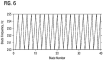
- FIG. 6 graphically illustrates alternate mistuning in a row of 40 turbine blades.
- the odd number blades have a frequency of 250Hz
- the even numbered blades have a frequency of 255 Hz.
- the difference in blade frequencies is 5 Hz. Consequently, the frequency of even numbered blades is 2% than the frequency of odd numbered blades, i.e., the amount of mistuning is 2%.
- the cross-sectional geometry of the airfoils about the rotation axis are essentially the same for both the high-frequency blades H and the low frequency blades L. This makes it easier to design the airfoil to have optimum aerodynamic efficiency since a uniform airfoil geometry has to be considered.
- the illustrated embodiments make it possible to employ alternate mistuning for blades with hollow airfoils, for example, containing internal cooling channels.
- the design of hollow airfoils is more constrained than the design of solid airfoils.
- the use of mistuned snubbers provide a possibility for implementing alternate mistuning for such hollow blades without compromising the aero-efficiency.
Landscapes
- Engineering & Computer Science (AREA)
- Mechanical Engineering (AREA)
- General Engineering & Computer Science (AREA)
- Turbine Rotor Nozzle Sealing (AREA)
- Structures Of Non-Positive Displacement Pumps (AREA)
Description
- The present invention relates to rotating blades in a turbomachine, and in particular, to a row of snubbered blades with alternate frequency mistuning for improved flutter resistance.
- Turbomachines, such as gas turbine engines include multiple stages of flow directing elements along a hot gas path in a turbine section of the gas turbine engine. Each turbine stage comprises a circumferential row of stationary vanes and a circumferential row of rotating blades arranged along an axial direction of the turbine section. Each row of blades may be mounted on a respective rotor disc, with the blades extending radially outward from the rotor disc into the hot gas path. A blade includes an airfoil extending span-wise along the radial direction from a root portion to a tip of the airfoil.
- Typical turbine blades at each stage are designed to be identical aerodynamically and mechanically. These identical blades are assembled together into the rotor disc to form a bladed rotor system. During engine operation, the bladed rotor system vibrates in system modes. This vibration may be more severe in large blades, such as in low pressure turbine stages. An important source of damping in the modes is from aerodynamic forces acting on the blades when the blades vibrate. Under certain conditions, the aerodynamic damping in some of the modes may become negative, which may cause the blades to flutter. When this happens, the vibratory response of the system tends to grow exponentially until the blades either reach a limit cycle or break. Even if the blades achieve a limit cycle, their amplitudes can still be large enough to cause the blades to fail from high cycle fatigue.
- In order to increase the blade natural frequency and decrease the tendency of the blades to flutter, blades may be provided with tip-shrouds or snubbers. The difference between a snubber and a tip-shroud is that a tip-shroud is disposed over the tip of the airfoil, while a snubber is generally disposed away from the tip, typically attached at a mid-span of the airfoil.
FIG. 1 illustrates turbine blades with tip-shrouds 90, whileFIG. 2-3 illustrate turbine blades with mid-span shrouds orsnubbers 30. Both tip-shrouds and snubbers work on the same principle: An airfoil is typically installed on the rotor disk with a pre-twist. During engine operation, the airfoil tends to untwist due to centrifugal forces. The tip-shroud or snubber, which is attached to the airfoil, comes into contact with adjacent tip-shrouds or snubbers, due to the rotation of the blades, to form a ring when the blades reach a certain rotational speed. The ring provides a constraint that causes the frequencies of the blades to increase, which decreases the tendency of the blades to flutter. - From
document EP 2 385 217 A2 a blade having asymmetrical mid-span structure portions and related bladed wheel structure for vibration damping is known. From documentUS 2011/142654 A1 a turbine blade damping device with controlled loading is known. From documentUS 2017/058681 A1 a removable attachable snubber assembly is known. All cited documents show different snubber designs for turbine blades. - However, there remains a room for improvement to better address the problem of blade vibration.
- Briefly, aspects of the present invention are directed to snubbered blades with alternate frequency mistuning for improved flutter resistance.
- According a first aspect of the present invention, a bladed rotor system for a turbomachine according to claim 1 is provided. Thereby the natural frequency of a blade in the second set differs from the natural frequency of a blade in the first set by a predetermined amount. Blades of the first set and the second set are positioned alternately in the row of blades, to provide a frequency mistuning to stabilize flutter of the blades.
- According a second aspect of the present invention, a blade according to
claim 6 is provided for a row of blades in a turbomachine. The blade is designed to be identical to a first set of blades or a second set of blades in the row. The blades of the second set are distinguished from the blades of the first set by a geometry of the snubber that is unique to the respective set, in which: the snubbers of the second set are attached to the respective airfoils at a different span-wise height than that of the snubbers of the first set. Thereby, the natural frequency of a blade in the second set differs from the natural frequency of a blade in the first set by a predetermined amount. Blades of the first set and the second set are positioned alternately in the row of blades, to provide a frequency mistuning to stabilize flutter of the blades. - The invention is shown in more detail by help of figures. The figures show preferred configurations and do not limit the scope of the invention.
-
FIG. 1 illustrates a row of rotating blades with tip-shrouds; -
FIG. 2 illustrates a row of rotating blades with snubbers; -
FIG. 3 is a perspective view of an individual blade with a snubber attached to mid-span of the blade airfoil; -
FIG. 4 is a schematic illustration of an axial end view of a bladed rotor system having alternately mistuned snubbers in accordance with an embodiment of the invention; -
FIG. 5 is a schematic illustration of an axial end view of a bladed rotor system having alternately mistuned snubbers in accordance with another embodiment of the invention; and -
FIG. 6 graphically illustrates alternate mistuning in a row of turbine blades. - In the following detailed description of the preferred embodiments, reference is made to the accompanying drawings that form a part hereof, and in which is shown by way of illustration, and not by way of limitation, a specific embodiment in which the invention may be practiced. It is to be understood that other embodiments may be utilized and that changes may be made without departing from the scope of the present invention.
- In the drawings, the direction A denotes an axial direction parallel to an axis of the turbine engine, while the directions R and C respectively denote a radial direction and a circumferential direction with respect to said axis of the turbine engine.
- Illustrated embodiments of the present invention are directed to snubbered turbine blades in a turbine section of a gas turbine engine. However, the embodiments herein are merely exemplary. Alternately, for example and without limitation, aspects of the present invention may be incorporated in fan blades at the entry of a compressor section of an aviation gas turbine engine.
- It has been found that alternate frequency mistuning can cause system modes to be distorted, so that the resulting new, mistuned system modes are stable, i.e., they all have positive aerodynamic damping. It is therefore desirable to be able to design blades with a certain amount of predetermined alternate mistuning. Alternate mistuning may be implemented in blades by having the blades in the blade row alternate between high and low frequencies in periodic fashion in the circumferential direction. So far, alternate mistuning of blades has been implemented by modifying the mass and/or geometry of the airfoil in alternate blades in a blade row.
- Embodiments of the present invention are based on the principle of modifying a geometry of the snubber for a set of blades in the blade row, so that said set of blades are mistuned, having a different frequency in relation to the rest of the blades in the blade row. Modifying the snubber geometry may involve modifying the radial (span-wise) location of snubbers. In accordance with the illustrated embodiments depicted in
FIG. 4-5 , a circumferential row of blades 14 mounted on arotor disc 12 may comprises a first set H of blades 14 and a second set L of blades 14. Theairfoils 16 in the first set H and the second L set of blades 14 may have essentially identical cross-sectional geometry about therotation axis 22. That is, the airfoil cross-sectional shape as well as the angle of the airfoil chord with therotation axis 22 may be substantially constant across the first set H and the second set L of blades 14. Further, in the context of the illustrated embodiments, it may be assumed that each blade 14 of the blade row has essentially identical fir-tree attachments (blade root) for mounting the blade 14 on therotor disc 12. The blades 14 of the second set L are distinguished from the blades 14 of the first set H by a geometry of thesnubber 30 that is unique to the respective set H or L. In particular, thesnubbers 30 of the second set L are attached to therespective airfoils 16 at a different span-wise or radial height than that of thesnubbers 30 of the first set H, which may change the free length of theairfoils 16 from the point ofsnubber attachment 34 to theairfoil tip 20. Thereby the natural frequency of a blade 14 in the second set L differs from the natural frequency of a blade 14 in the first set H by a predetermined amount. In the illustrated examples, the blades 14 in the second set L are mistuned, having a lower frequency than the blades 14 of the first set H. The blades 14 of the first set H and the second set L may be alternately arranged in the blade row, to provide frequency mistuning to stabilize flutter of the blades 14. - In the context of the specification, a snubber is understood to be a shroud which is attached at a mid-span region of a blade airfoil. A mid-span region may be understood to be any region located between the root and the tip of the airfoil. In one example, mid-span snubbers may be located between 40-70% of the span of the airfoil as measured from the root.
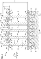
- Referring now to
FIG. 4 , a portion ofbladed rotor system 10 is illustrated in accordance with one embodiment of the present invention. Thebladed rotor system 10 includes a circumferential row of blades 14 mounted on arotor disc 12. Each blade 14 comprises anairfoil 16 extending span-wise along a radial direction from aroot portion 18 to anairfoil tip 20. As known to one skilled in the art, theairfoil 16 may comprise a generallyconcave pressure side 2 and a generallyconvex suction side 4, joined at aleading edge 6 and at a trailing edge (not shown). A radially inner end of theairfoil 16 is coupled to aroot 18 at aplatform 24. In the illustrated embodiment, theroot 18 has a fir-tree shape, which fits into a correspondingly shapedslot 26 in arotor disk 12. In order to increase the blade natural frequency and decrease the tendency to flutter, the blade 14 may be provided with acircumferentially extending snubber 30 attached to theairfoil 16 at a mid-span region of theairfoil 16. Theplatforms 24 of adjacent blades 14 in the blade row abut each other to form an inner flowpath boundary for a hot gas, and theairfoils 16 extend radially outward across the flowpath. - Each
snubber 30 comprises a pressureside snubber portion 30a extending from thepressure side 2 of therespective airfoil 16 to a pressureside snubber edge 42, and a suctionside snubber portion 30b extending from thesuction side 4 of therespective airfoil 16 to a suctionside snubber edge 44. Eachblade airfoil 16 may be twisted about its span-wise axis. During engine operation, the blades 14 rotate about arotation axis 22, whereby centrifugal and aerodynamic forces untwist eachblade airfoil 16 in the blade row so that the pressureside snubber edge 42 of eachsnubber 30 abuts the suctionside snubber edge 44 of a neighboringsnubber 30, to form a ring. The abutting contact between neighboringsnubbers 30 helps to limit the untwisting of the blade and establish the blade's precise orientation during operation. The snubber ring provides a constraint that causes the frequencies of the blades to increase, which decreases the tendency of the blades to flutter. - In accordance with the illustrated embodiment, a geometry of the
snubber 30 may be modified for a set L of blades in the blade row, so that said set of blades L are mistuned in relation to the remaining blades H in the blade row. In this embodiment, this is achieved by moving the location of the point ofattachment 34 of theairfoil 16 andsnubber 30 to a radially lower height for blades 14 in the second set L, in relation to that of the blades 14 in the first set H. As shown, each blade 14 of the first set H is adjacent, on either side, to a neighboring blade 14 of the second set L. The shift in position of the point ofattachment 34 between the adjacent blades 14 is depicted as Δr. As a result, a free length re2 of theairfoils 16 in the second set L is larger than a free length re1 of theairfoils 16 in the first set H. The free length of anairfoil 16 being may be defined as a radial distance between theairfoil tip 20 and a point ofattachment 34 of theairfoil 16 with the associatedsnubber 30. Because of the difference in free lengths of theadjacent airfoils 16, the blades 14 in the second row L have a slightly lower frequency than the blades 14 in the first set H. The total radial height r from the root to the airfoil tip is typically constant for eachairfoil 16 across the first and second sets of blades. - In a preferred embodiment,
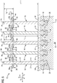
snubbers 30 of adjacent blades 14 of the row of blades meet at a constant radial height rr. This may be achieved by designingadjacent snubbers 30 with alternate orientations in relation to the radial direction. In the illustrated embodiment, the pressureside snubber portion 30a and the suctionside snubber portion 30b of thesnubbers 30 in the second set L are oriented differently than the pressureside snubber portion 30a and the suctionside snubber portion 30b of thesnubbers 30 in the first set H. In particular, the pressureside snubber portion 30a and the suctionside snubber portion 30b of eachsnubber 30 in the first set H extends radially inwardly from the point ofattachment 34 toward the respective snubber edges 42, 44. Correspondingly, the pressureside snubber portion 30a and the suctionside snubber portion 30b of eachsnubber 30 in the second set L extends radially outwardly from the point ofattachment 34 toward the respective snubber edges 42, 44. - In the embodiment illustrated in
FIG. 4 , the pressure side and suctionside snubber portions side snubber portion 30a and the suctionside snubber portion 30b of eachsnubber 30 in the first set H extends radially inwardly from the point ofattachment 34 along a linear profile. Correspondingly, the pressureside snubber portion 30a and the suctionside snubber portion 30b of eachsnubber 30 in the second set L extends radially outwardly from the point ofattachment 34 along a linear profile. However, the above configuration is exemplary and other snubber geometries may be considered. For example, in an alternate embodiment shown inFIG. 5 , thesnubbers 30 may have a curved profile extending radially outward or radially inward. As shown in this example, the pressureside snubber portion 30a and the suctionside snubber portion 30b of eachsnubber 30 in the first set H is curved radially inward from the point ofattachment 34. Correspondingly, the pressureside snubber portion 30a and the suctionside snubber portion 30b of eachsnubber 30 in the second set L is curved radially outward from the point ofattachment 34. In each of the illustrated embodiments, thesnubbers 30 in the first set H and the second set L may have the same mean radial thickness. - As an example, to effectively stabilize flutter, the snubber geometries may be modified to achieve a mistuning of about 1.5 - 2 % above manufacturing tolerances.
FIG. 6 graphically illustrates alternate mistuning in a row of 40 turbine blades. Herein, the odd number blades have a frequency of 250Hz, while the even numbered blades have a frequency of 255 Hz. In this example, the difference in blade frequencies is 5 Hz. Consequently, the frequency of even numbered blades is 2% than the frequency of odd numbered blades, i.e., the amount of mistuning is 2%. - As illustrated above, the cross-sectional geometry of the airfoils about the rotation axis are essentially the same for both the high-frequency blades H and the low frequency blades L. This makes it easier to design the airfoil to have optimum aerodynamic efficiency since a uniform airfoil geometry has to be considered. Moreover, the illustrated embodiments make it possible to employ alternate mistuning for blades with hollow airfoils, for example, containing internal cooling channels. The design of hollow airfoils is more constrained than the design of solid airfoils. The use of mistuned snubbers provide a possibility for implementing alternate mistuning for such hollow blades without compromising the aero-efficiency.
Claims (8)
- A bladed rotor system (10) for a turbomachine, comprising:a circumferential row of blades (14) mounted on a rotor disc (12), each blade (14) comprising:an airfoil (16) extending span-wise along a radial direction from a root portion (18) to an airfoil tip (20); anda circumferentially extending snubber (30) attached to the airfoil (16) at a mid-span region of the airfoil (16),wherein in operation, snubbers (30) of adjacent blades (14) abut circumferentially,wherein the row of blades (14) comprises a first set (H) of blades (14) and a second set (L) of blades (14), wherein the blades (14) of the second set (L) are distinguished from the blades (14) of the first set (H) by a geometry of the snubber (30) that is unique to the respective set (H, L), in which:
the snubbers (30) of the second set (L) are attached to the respective airfoils (16) at a different span-wise height than that of the snubbers (30) of the first set (H), whereby the natural frequency of a blade (14) in the second set (L) differs from the natural frequency of a blade (14) in the first set (H) by a predetermined amount,wherein blades (14) of the first set (H) and the second set (L) are positioned alternately in the row of blades (14), to provide a frequency mistuning to stabilize flutter of the blades (14),wherein a free length (re2) of the airfoils (16) in the second set (L) is larger than a free length (re1) of the airfoils (16) in the first set (H),the free length (re1, re2) of an airfoil (16) being defined as a radial distance between the airfoil tip (20) and a point of attachment (34) of the airfoil (16) with the associated snubber (30),wherein each snubber (30) comprises a pressure side snubber portion (30a) extending from a pressure side (2) of the respective airfoil (16) and a suction side snubber portion (30b) extending from a suction side (4) of the respective airfoil (16),wherein the pressure side snubber portion (30a) and the suction side snubber portion (30b) of the snubbers (30) in the second set (L) are oriented differently than the pressure side snubber portion (30a) and the suction side snubber portion (30b) of the snubbers (30) in the first set (H), such that snubbers (30) of adjacent blades (14) of the row of blades meet at a constant radial height (rr), andcharacterised in thatthe pressure side snubber portion (30a) and the suction side snubber portion (30b) of each snubber (30) in the first set (H) extends radially inwardly from said point of attachment (34), andthe pressure side snubber portion (30a) and the suction side snubber portion (30b) of each snubber (30) in the second set (L) extends radially outwardly from said point of attachment (34). - The bladed rotor system (10) according to claim 1, wherein the airfoils (16) in the first (H) and second (L) set having substantially identical cross-sectional geometry about a rotation axis (22).
- The bladed rotor system (10) according to claim 1, wherein the pressure side snubber portion (30a) and the suction side snubber portion (30b) of each snubber (30) in each of the first (H) and second (L) sets extends radially inwardly or outwardly from said point of attachment (34) along a linear profile.
- The bladed rotor system (10) according to claim 1, whereinthe pressure side snubber portion (30a) and the suction side snubber portion (30b) of each snubber (30) in the first set (H) is curved radially inward from said point of attachment (34), andthe pressure side snubber portion (30a) and the suction side snubber portion (30b) of each snubber (30) in the second set (L) is curved radially outward from said point of attachment (34).
- The bladed rotor system (10) according to claim 1, wherein the snubbers (30) in the first set (H) and the second set (L) have the same mean radial thickness.
- A blade (14) for a row of blades in a bladed rotor system (10) for a turbomachine according to any of the previous claims 1 to 5, the blade (14) comprising:an airfoil (16) extending span-wise along a radial direction from a root portion (18) to an airfoil tip (20); anda circumferentially extending snubber (30) attached to the airfoil (16) at a mid-span region of the airfoil,wherein the blade (14) is designed to be identical to blades (14) in the row, wherein the blade (14) comprising a snubber (30), wherein the snubber (30) comprises a pressure side snubber portion (30a) extending from a pressure side (2) of the airfoil (16) and a suction side snubber portion (30b) extending from a suction side (4) of the airfoil (16), andcharacterised in that the pressure side snubber portion (30a) and the suction side snubber portion (30b) of the snubber extend radially outwardly from a point of attachment (34) of the airfoil (16) to the snubber (30).
- The blade (14) according to claim 6, wherein the pressure side snubber portion (30a) and the suction side snubber portion (30b) of the snubber (30) extend radially outwardly from said point of attachment (34) along a straight profile.
- The blade (14) according to claim 6, wherein the pressure side snubber portion (30a) and the suction side snubber portion (30b) of the snubber (30) curve outward from said point of attachment (34).
Applications Claiming Priority (2)
| Application Number | Priority Date | Filing Date | Title |
|---|---|---|---|
| US201762470446P | 2017-03-13 | 2017-03-13 | |
| PCT/US2018/019707 WO2018169668A1 (en) | 2017-03-13 | 2018-02-26 | Snubbered blades with improved flutter resistance |
Publications (2)
| Publication Number | Publication Date |
|---|---|
| EP3596312A1 EP3596312A1 (en) | 2020-01-22 |
| EP3596312B1 true EP3596312B1 (en) | 2021-12-15 |
Family
ID=61622705
Family Applications (1)
| Application Number | Title | Priority Date | Filing Date |
|---|---|---|---|
| EP18710616.6A Active EP3596312B1 (en) | 2017-03-13 | 2018-02-26 | Snubbered blades with improved flutter resistance |
Country Status (5)
| Country | Link |
|---|---|
| US (1) | US20200032659A1 (en) |
| EP (1) | EP3596312B1 (en) |
| JP (1) | JP6955021B2 (en) |
| CN (1) | CN110382824B (en) |
| WO (1) | WO2018169668A1 (en) |
Families Citing this family (3)
| Publication number | Priority date | Publication date | Assignee | Title |
|---|---|---|---|---|
| US11767760B2 (en) * | 2020-11-04 | 2023-09-26 | Honeywell International Inc. | Geometric approach to stress reduced intra-flow path shrouds for tuning modal responses in ram air turbine rotors |
| EP4112884A1 (en) * | 2021-07-01 | 2023-01-04 | Doosan Enerbility Co., Ltd. | Blade for a turbomachine, blade assembly, and turbine |
| DE102022200711A1 (en) | 2022-01-24 | 2023-07-27 | Siemens Energy Global GmbH & Co. KG | Partially coated turbine blade, rotor and method |
Family Cites Families (7)
| Publication number | Priority date | Publication date | Assignee | Title |
|---|---|---|---|---|
| US1618284A (en) * | 1925-05-22 | 1927-02-22 | Westinghouse Electric & Mfg Co | Turbine-blade bracing |
| US3045969A (en) * | 1958-09-26 | 1962-07-24 | Escher Wyss Ag | Vibration damping device for turbo-machine |
| JP3618252B2 (en) * | 1999-04-19 | 2005-02-09 | 株式会社大林組 | Event square with a large roof |
| US8540488B2 (en) * | 2009-12-14 | 2013-09-24 | Siemens Energy, Inc. | Turbine blade damping device with controlled loading |
| RU2010117972A (en) * | 2010-05-06 | 2011-11-20 | Дженерал Электрик Компани (US) | WRAPPED WHEEL AND SHOVEL |
| US20150089809A1 (en) * | 2013-09-27 | 2015-04-02 | General Electric Company | Scaling to custom-sized turbomachine airfoil method |
| US9957818B2 (en) * | 2015-08-28 | 2018-05-01 | Siemens Energy, Inc. | Removably attachable snubber assembly |
-
2018
- 2018-02-26 JP JP2019550196A patent/JP6955021B2/en active Active
- 2018-02-26 CN CN201880018114.5A patent/CN110382824B/en active Active
- 2018-02-26 WO PCT/US2018/019707 patent/WO2018169668A1/en unknown
- 2018-02-26 EP EP18710616.6A patent/EP3596312B1/en active Active
- 2018-02-26 US US16/491,259 patent/US20200032659A1/en not_active Abandoned
Non-Patent Citations (1)
| Title |
|---|
| None * |
Also Published As
| Publication number | Publication date |
|---|---|
| JP6955021B2 (en) | 2021-10-27 |
| CN110382824A (en) | 2019-10-25 |
| JP2020510159A (en) | 2020-04-02 |
| CN110382824B (en) | 2022-06-07 |
| EP3596312A1 (en) | 2020-01-22 |
| US20200032659A1 (en) | 2020-01-30 |
| WO2018169668A1 (en) | 2018-09-20 |
Similar Documents
| Publication | Publication Date | Title |
|---|---|---|
| EP2942481B1 (en) | Rotor for a gas turbine engine | |
| EP1111188B1 (en) | Swept airfoil with barrel shaped leading edge | |
| US8591195B2 (en) | Turbine blade with pressure side stiffening rib | |
| US8221083B2 (en) | Asymmetrical rotor blade fir-tree attachment | |
| EP3880936B1 (en) | Bladed rotor system and method of servicing a bladed rotor system | |
| EP3596312B1 (en) | Snubbered blades with improved flutter resistance | |
| US20170191367A1 (en) | Variable stator vane undercut button | |
| EP2581556A2 (en) | Variable vanes with non uniform lean | |
| US11353038B2 (en) | Compressor rotor for supersonic flutter and/or resonant stress mitigation | |
| WO2018175356A1 (en) | Alternately mistuned blades with modified under-platform dampers | |
| EP3596311B1 (en) | Shrouded blades with improved flutter resistance | |
| EP3456920B1 (en) | Mistuned rotor for gas turbine engine | |
| EP3765713B1 (en) | Mistuning of turbine blades with one or more internal cavities | |
| JP2004263602A (en) | Nozzle blade, moving blade, and turbine stage of axial-flow turbine | |
| JP2020159275A (en) | Turbine stator blade and turbine |
Legal Events
| Date | Code | Title | Description |
|---|---|---|---|
| STAA | Information on the status of an ep patent application or granted ep patent |
Free format text: STATUS: UNKNOWN |
|
| STAA | Information on the status of an ep patent application or granted ep patent |
Free format text: STATUS: THE INTERNATIONAL PUBLICATION HAS BEEN MADE |
|
| PUAI | Public reference made under article 153(3) epc to a published international application that has entered the european phase |
Free format text: ORIGINAL CODE: 0009012 |
|
| STAA | Information on the status of an ep patent application or granted ep patent |
Free format text: STATUS: REQUEST FOR EXAMINATION WAS MADE |
|
| 17P | Request for examination filed |
Effective date: 20190911 |
|
| AK | Designated contracting states |
Kind code of ref document: A1 Designated state(s): AL AT BE BG CH CY CZ DE DK EE ES FI FR GB GR HR HU IE IS IT LI LT LU LV MC MK MT NL NO PL PT RO RS SE SI SK SM TR |
|
| AX | Request for extension of the european patent |
Extension state: BA ME |
|
| DAV | Request for validation of the european patent (deleted) | ||
| DAX | Request for extension of the european patent (deleted) | ||
| STAA | Information on the status of an ep patent application or granted ep patent |
Free format text: STATUS: EXAMINATION IS IN PROGRESS |
|
| 17Q | First examination report despatched |
Effective date: 20201201 |
|
| RAP1 | Party data changed (applicant data changed or rights of an application transferred) |
Owner name: SIEMENS ENERGY GLOBAL GMBH & CO. KG |
|
| GRAP | Despatch of communication of intention to grant a patent |
Free format text: ORIGINAL CODE: EPIDOSNIGR1 |
|
| STAA | Information on the status of an ep patent application or granted ep patent |
Free format text: STATUS: GRANT OF PATENT IS INTENDED |
|
| INTG | Intention to grant announced |
Effective date: 20210803 |
|
| GRAS | Grant fee paid |
Free format text: ORIGINAL CODE: EPIDOSNIGR3 |
|
| GRAA | (expected) grant |
Free format text: ORIGINAL CODE: 0009210 |
|
| STAA | Information on the status of an ep patent application or granted ep patent |
Free format text: STATUS: THE PATENT HAS BEEN GRANTED |
|
| AK | Designated contracting states |
Kind code of ref document: B1 Designated state(s): AL AT BE BG CH CY CZ DE DK EE ES FI FR GB GR HR HU IE IS IT LI LT LU LV MC MK MT NL NO PL PT RO RS SE SI SK SM TR |
|
| REG | Reference to a national code |
Ref country code: GB Ref legal event code: FG4D Ref country code: CH Ref legal event code: EP |
|
| REG | Reference to a national code |
Ref country code: IE Ref legal event code: FG4D Ref country code: DE Ref legal event code: R096 Ref document number: 602018028164 Country of ref document: DE |
|
| REG | Reference to a national code |
Ref country code: AT Ref legal event code: REF Ref document number: 1455637 Country of ref document: AT Kind code of ref document: T Effective date: 20220115 |
|
| REG | Reference to a national code |
Ref country code: LT Ref legal event code: MG9D |
|
| REG | Reference to a national code |
Ref country code: NL Ref legal event code: MP Effective date: 20211215 |
|
| PG25 | Lapsed in a contracting state [announced via postgrant information from national office to epo] |
Ref country code: RS Free format text: LAPSE BECAUSE OF FAILURE TO SUBMIT A TRANSLATION OF THE DESCRIPTION OR TO PAY THE FEE WITHIN THE PRESCRIBED TIME-LIMIT Effective date: 20211215 Ref country code: LT Free format text: LAPSE BECAUSE OF FAILURE TO SUBMIT A TRANSLATION OF THE DESCRIPTION OR TO PAY THE FEE WITHIN THE PRESCRIBED TIME-LIMIT Effective date: 20211215 Ref country code: FI Free format text: LAPSE BECAUSE OF FAILURE TO SUBMIT A TRANSLATION OF THE DESCRIPTION OR TO PAY THE FEE WITHIN THE PRESCRIBED TIME-LIMIT Effective date: 20211215 Ref country code: BG Free format text: LAPSE BECAUSE OF FAILURE TO SUBMIT A TRANSLATION OF THE DESCRIPTION OR TO PAY THE FEE WITHIN THE PRESCRIBED TIME-LIMIT Effective date: 20220315 |
|
| REG | Reference to a national code |
Ref country code: AT Ref legal event code: MK05 Ref document number: 1455637 Country of ref document: AT Kind code of ref document: T Effective date: 20211215 |
|
| PG25 | Lapsed in a contracting state [announced via postgrant information from national office to epo] |
Ref country code: SE Free format text: LAPSE BECAUSE OF FAILURE TO SUBMIT A TRANSLATION OF THE DESCRIPTION OR TO PAY THE FEE WITHIN THE PRESCRIBED TIME-LIMIT Effective date: 20211215 Ref country code: NO Free format text: LAPSE BECAUSE OF FAILURE TO SUBMIT A TRANSLATION OF THE DESCRIPTION OR TO PAY THE FEE WITHIN THE PRESCRIBED TIME-LIMIT Effective date: 20220315 Ref country code: LV Free format text: LAPSE BECAUSE OF FAILURE TO SUBMIT A TRANSLATION OF THE DESCRIPTION OR TO PAY THE FEE WITHIN THE PRESCRIBED TIME-LIMIT Effective date: 20211215 Ref country code: HR Free format text: LAPSE BECAUSE OF FAILURE TO SUBMIT A TRANSLATION OF THE DESCRIPTION OR TO PAY THE FEE WITHIN THE PRESCRIBED TIME-LIMIT Effective date: 20211215 Ref country code: GR Free format text: LAPSE BECAUSE OF FAILURE TO SUBMIT A TRANSLATION OF THE DESCRIPTION OR TO PAY THE FEE WITHIN THE PRESCRIBED TIME-LIMIT Effective date: 20220316 |
|
| PG25 | Lapsed in a contracting state [announced via postgrant information from national office to epo] |
Ref country code: NL Free format text: LAPSE BECAUSE OF FAILURE TO SUBMIT A TRANSLATION OF THE DESCRIPTION OR TO PAY THE FEE WITHIN THE PRESCRIBED TIME-LIMIT Effective date: 20211215 |
|
| PG25 | Lapsed in a contracting state [announced via postgrant information from national office to epo] |
Ref country code: SM Free format text: LAPSE BECAUSE OF FAILURE TO SUBMIT A TRANSLATION OF THE DESCRIPTION OR TO PAY THE FEE WITHIN THE PRESCRIBED TIME-LIMIT Effective date: 20211215 Ref country code: SK Free format text: LAPSE BECAUSE OF FAILURE TO SUBMIT A TRANSLATION OF THE DESCRIPTION OR TO PAY THE FEE WITHIN THE PRESCRIBED TIME-LIMIT Effective date: 20211215 Ref country code: RO Free format text: LAPSE BECAUSE OF FAILURE TO SUBMIT A TRANSLATION OF THE DESCRIPTION OR TO PAY THE FEE WITHIN THE PRESCRIBED TIME-LIMIT Effective date: 20211215 Ref country code: PT Free format text: LAPSE BECAUSE OF FAILURE TO SUBMIT A TRANSLATION OF THE DESCRIPTION OR TO PAY THE FEE WITHIN THE PRESCRIBED TIME-LIMIT Effective date: 20220418 Ref country code: ES Free format text: LAPSE BECAUSE OF FAILURE TO SUBMIT A TRANSLATION OF THE DESCRIPTION OR TO PAY THE FEE WITHIN THE PRESCRIBED TIME-LIMIT Effective date: 20211215 Ref country code: EE Free format text: LAPSE BECAUSE OF FAILURE TO SUBMIT A TRANSLATION OF THE DESCRIPTION OR TO PAY THE FEE WITHIN THE PRESCRIBED TIME-LIMIT Effective date: 20211215 Ref country code: CZ Free format text: LAPSE BECAUSE OF FAILURE TO SUBMIT A TRANSLATION OF THE DESCRIPTION OR TO PAY THE FEE WITHIN THE PRESCRIBED TIME-LIMIT Effective date: 20211215 |
|
| PG25 | Lapsed in a contracting state [announced via postgrant information from national office to epo] |
Ref country code: PL Free format text: LAPSE BECAUSE OF FAILURE TO SUBMIT A TRANSLATION OF THE DESCRIPTION OR TO PAY THE FEE WITHIN THE PRESCRIBED TIME-LIMIT Effective date: 20211215 Ref country code: AT Free format text: LAPSE BECAUSE OF FAILURE TO SUBMIT A TRANSLATION OF THE DESCRIPTION OR TO PAY THE FEE WITHIN THE PRESCRIBED TIME-LIMIT Effective date: 20211215 |
|
| REG | Reference to a national code |
Ref country code: DE Ref legal event code: R097 Ref document number: 602018028164 Country of ref document: DE |
|
| PG25 | Lapsed in a contracting state [announced via postgrant information from national office to epo] |
Ref country code: MC Free format text: LAPSE BECAUSE OF FAILURE TO SUBMIT A TRANSLATION OF THE DESCRIPTION OR TO PAY THE FEE WITHIN THE PRESCRIBED TIME-LIMIT Effective date: 20211215 Ref country code: IS Free format text: LAPSE BECAUSE OF FAILURE TO SUBMIT A TRANSLATION OF THE DESCRIPTION OR TO PAY THE FEE WITHIN THE PRESCRIBED TIME-LIMIT Effective date: 20220415 |
|
| REG | Reference to a national code |
Ref country code: CH Ref legal event code: PL |
|
| PLBE | No opposition filed within time limit |
Free format text: ORIGINAL CODE: 0009261 |
|
| STAA | Information on the status of an ep patent application or granted ep patent |
Free format text: STATUS: NO OPPOSITION FILED WITHIN TIME LIMIT |
|
| REG | Reference to a national code |
Ref country code: BE Ref legal event code: MM Effective date: 20220228 |
|
| PG25 | Lapsed in a contracting state [announced via postgrant information from national office to epo] |
Ref country code: LU Free format text: LAPSE BECAUSE OF NON-PAYMENT OF DUE FEES Effective date: 20220226 Ref country code: DK Free format text: LAPSE BECAUSE OF FAILURE TO SUBMIT A TRANSLATION OF THE DESCRIPTION OR TO PAY THE FEE WITHIN THE PRESCRIBED TIME-LIMIT Effective date: 20211215 Ref country code: AL Free format text: LAPSE BECAUSE OF FAILURE TO SUBMIT A TRANSLATION OF THE DESCRIPTION OR TO PAY THE FEE WITHIN THE PRESCRIBED TIME-LIMIT Effective date: 20211215 |
|
| 26N | No opposition filed |
Effective date: 20220916 |
|
| GBPC | Gb: european patent ceased through non-payment of renewal fee |
Effective date: 20220315 |
|
| PG25 | Lapsed in a contracting state [announced via postgrant information from national office to epo] |
Ref country code: SI Free format text: LAPSE BECAUSE OF FAILURE TO SUBMIT A TRANSLATION OF THE DESCRIPTION OR TO PAY THE FEE WITHIN THE PRESCRIBED TIME-LIMIT Effective date: 20211215 |
|
| PG25 | Lapsed in a contracting state [announced via postgrant information from national office to epo] |
Ref country code: FR Free format text: LAPSE BECAUSE OF NON-PAYMENT OF DUE FEES Effective date: 20220228 |
|
| PG25 | Lapsed in a contracting state [announced via postgrant information from national office to epo] |
Ref country code: LI Free format text: LAPSE BECAUSE OF NON-PAYMENT OF DUE FEES Effective date: 20220228 Ref country code: IE Free format text: LAPSE BECAUSE OF NON-PAYMENT OF DUE FEES Effective date: 20220226 Ref country code: GB Free format text: LAPSE BECAUSE OF NON-PAYMENT OF DUE FEES Effective date: 20220315 Ref country code: CH Free format text: LAPSE BECAUSE OF NON-PAYMENT OF DUE FEES Effective date: 20220228 |
|
| PG25 | Lapsed in a contracting state [announced via postgrant information from national office to epo] |
Ref country code: BE Free format text: LAPSE BECAUSE OF NON-PAYMENT OF DUE FEES Effective date: 20220228 |
|
| PG25 | Lapsed in a contracting state [announced via postgrant information from national office to epo] |
Ref country code: IT Free format text: LAPSE BECAUSE OF FAILURE TO SUBMIT A TRANSLATION OF THE DESCRIPTION OR TO PAY THE FEE WITHIN THE PRESCRIBED TIME-LIMIT Effective date: 20211215 |
|
| P01 | Opt-out of the competence of the unified patent court (upc) registered |
Effective date: 20231222 |
|
| PG25 | Lapsed in a contracting state [announced via postgrant information from national office to epo] |
Ref country code: MK Free format text: LAPSE BECAUSE OF FAILURE TO SUBMIT A TRANSLATION OF THE DESCRIPTION OR TO PAY THE FEE WITHIN THE PRESCRIBED TIME-LIMIT Effective date: 20211215 Ref country code: CY Free format text: LAPSE BECAUSE OF FAILURE TO SUBMIT A TRANSLATION OF THE DESCRIPTION OR TO PAY THE FEE WITHIN THE PRESCRIBED TIME-LIMIT Effective date: 20211215 |
|
| PGFP | Annual fee paid to national office [announced via postgrant information from national office to epo] |
Ref country code: DE Payment date: 20240228 Year of fee payment: 7 |