EP3594690B1 - System for processing lateral flow assay devices - Google Patents
System for processing lateral flow assay devices Download PDFInfo
- Publication number
- EP3594690B1 EP3594690B1 EP19193656.6A EP19193656A EP3594690B1 EP 3594690 B1 EP3594690 B1 EP 3594690B1 EP 19193656 A EP19193656 A EP 19193656A EP 3594690 B1 EP3594690 B1 EP 3594690B1
- Authority
- EP
- European Patent Office
- Prior art keywords
- analyzer
- lateral flow
- flow assay
- sample
- test elements
- Prior art date
- Legal status (The legal status is an assumption and is not a legal conclusion. Google has not performed a legal analysis and makes no representation as to the accuracy of the status listed.)
- Active
Links
- 238000003556 assay Methods 0.000 title claims description 128
- 238000012545 processing Methods 0.000 title description 12
- 238000001514 detection method Methods 0.000 claims description 60
- 238000012360 testing method Methods 0.000 claims description 60
- 238000006243 chemical reaction Methods 0.000 claims description 38
- 238000004458 analytical method Methods 0.000 claims description 33
- 239000012530 fluid Substances 0.000 claims description 33
- 238000003860 storage Methods 0.000 claims description 24
- 230000007246 mechanism Effects 0.000 claims description 21
- 239000010409 thin film Substances 0.000 claims description 20
- 238000000034 method Methods 0.000 claims description 10
- 238000007704 wet chemistry method Methods 0.000 claims description 10
- 238000003018 immunoassay Methods 0.000 claims description 9
- 230000008569 process Effects 0.000 claims description 7
- 239000000523 sample Substances 0.000 description 96
- 239000003153 chemical reaction reagent Substances 0.000 description 67
- 239000012491 analyte Substances 0.000 description 17
- 239000000463 material Substances 0.000 description 15
- 238000013461 design Methods 0.000 description 14
- 239000000758 substrate Substances 0.000 description 14
- 239000007788 liquid Substances 0.000 description 12
- 230000027455 binding Effects 0.000 description 11
- 230000008901 benefit Effects 0.000 description 9
- 230000000712 assembly Effects 0.000 description 8
- 238000000429 assembly Methods 0.000 description 8
- 238000005259 measurement Methods 0.000 description 7
- 241001474791 Proboscis Species 0.000 description 6
- 238000011068 loading method Methods 0.000 description 6
- 102000004169 proteins and genes Human genes 0.000 description 6
- 108090000623 proteins and genes Proteins 0.000 description 6
- 230000002829 reductive effect Effects 0.000 description 6
- 210000004369 blood Anatomy 0.000 description 5
- 239000008280 blood Substances 0.000 description 5
- -1 calibration Substances 0.000 description 5
- 238000005516 engineering process Methods 0.000 description 5
- 230000002285 radioactive effect Effects 0.000 description 5
- 239000004793 Polystyrene Substances 0.000 description 4
- 238000010348 incorporation Methods 0.000 description 4
- 238000011534 incubation Methods 0.000 description 4
- 239000004816 latex Substances 0.000 description 4
- 229920000126 latex Polymers 0.000 description 4
- 230000003287 optical effect Effects 0.000 description 4
- 210000002381 plasma Anatomy 0.000 description 4
- 239000004033 plastic Substances 0.000 description 4
- 229920003023 plastic Polymers 0.000 description 4
- 229920000058 polyacrylate Polymers 0.000 description 4
- 229920000642 polymer Polymers 0.000 description 4
- 229920002223 polystyrene Polymers 0.000 description 4
- 239000011148 porous material Substances 0.000 description 4
- 230000000717 retained effect Effects 0.000 description 4
- 239000000020 Nitrocellulose Substances 0.000 description 3
- FJWGYAHXMCUOOM-QHOUIDNNSA-N [(2s,3r,4s,5r,6r)-2-[(2r,3r,4s,5r,6s)-4,5-dinitrooxy-2-(nitrooxymethyl)-6-[(2r,3r,4s,5r,6s)-4,5,6-trinitrooxy-2-(nitrooxymethyl)oxan-3-yl]oxyoxan-3-yl]oxy-3,5-dinitrooxy-6-(nitrooxymethyl)oxan-4-yl] nitrate Chemical compound O([C@@H]1O[C@@H]([C@H]([C@H](O[N+]([O-])=O)[C@H]1O[N+]([O-])=O)O[C@H]1[C@@H]([C@@H](O[N+]([O-])=O)[C@H](O[N+]([O-])=O)[C@@H](CO[N+]([O-])=O)O1)O[N+]([O-])=O)CO[N+](=O)[O-])[C@@H]1[C@@H](CO[N+]([O-])=O)O[C@@H](O[N+]([O-])=O)[C@H](O[N+]([O-])=O)[C@H]1O[N+]([O-])=O FJWGYAHXMCUOOM-QHOUIDNNSA-N 0.000 description 3
- 239000000427 antigen Substances 0.000 description 3
- 108091007433 antigens Proteins 0.000 description 3
- 102000036639 antigens Human genes 0.000 description 3
- 238000000576 coating method Methods 0.000 description 3
- 229920001577 copolymer Polymers 0.000 description 3
- 239000011888 foil Substances 0.000 description 3
- 238000002347 injection Methods 0.000 description 3
- 239000007924 injection Substances 0.000 description 3
- 239000002184 metal Substances 0.000 description 3
- 229910052751 metal Inorganic materials 0.000 description 3
- 229920001220 nitrocellulos Polymers 0.000 description 3
- 150000007523 nucleic acids Chemical class 0.000 description 3
- 229920000515 polycarbonate Polymers 0.000 description 3
- 239000004417 polycarbonate Substances 0.000 description 3
- 239000000243 solution Substances 0.000 description 3
- 239000000126 substance Substances 0.000 description 3
- 210000001519 tissue Anatomy 0.000 description 3
- YBJHBAHKTGYVGT-ZKWXMUAHSA-N (+)-Biotin Chemical group N1C(=O)N[C@@H]2[C@H](CCCCC(=O)O)SC[C@@H]21 YBJHBAHKTGYVGT-ZKWXMUAHSA-N 0.000 description 2
- 241000894006 Bacteria Species 0.000 description 2
- 108090000790 Enzymes Proteins 0.000 description 2
- 102000004190 Enzymes Human genes 0.000 description 2
- 241001465754 Metazoa Species 0.000 description 2
- 239000004698 Polyethylene Substances 0.000 description 2
- 239000004743 Polypropylene Substances 0.000 description 2
- 206010036790 Productive cough Diseases 0.000 description 2
- PPBRXRYQALVLMV-UHFFFAOYSA-N Styrene Chemical compound C=CC1=CC=CC=C1 PPBRXRYQALVLMV-UHFFFAOYSA-N 0.000 description 2
- 230000009471 action Effects 0.000 description 2
- 230000008859 change Effects 0.000 description 2
- 239000003795 chemical substances by application Substances 0.000 description 2
- 239000011248 coating agent Substances 0.000 description 2
- 238000004891 communication Methods 0.000 description 2
- 238000010276 construction Methods 0.000 description 2
- 229920001971 elastomer Polymers 0.000 description 2
- 239000000806 elastomer Substances 0.000 description 2
- 229920001600 hydrophobic polymer Polymers 0.000 description 2
- 230000006872 improvement Effects 0.000 description 2
- 238000001746 injection moulding Methods 0.000 description 2
- 230000002452 interceptive effect Effects 0.000 description 2
- 238000004519 manufacturing process Methods 0.000 description 2
- 239000003550 marker Substances 0.000 description 2
- 239000011104 metalized film Substances 0.000 description 2
- 150000002739 metals Chemical class 0.000 description 2
- 239000000203 mixture Substances 0.000 description 2
- 102000039446 nucleic acids Human genes 0.000 description 2
- 108020004707 nucleic acids Proteins 0.000 description 2
- 230000036961 partial effect Effects 0.000 description 2
- 239000013610 patient sample Substances 0.000 description 2
- 229920000728 polyester Polymers 0.000 description 2
- 229920000573 polyethylene Polymers 0.000 description 2
- 229920001155 polypropylene Polymers 0.000 description 2
- 239000000376 reactant Substances 0.000 description 2
- 210000003802 sputum Anatomy 0.000 description 2
- 208000024794 sputum Diseases 0.000 description 2
- 239000000725 suspension Substances 0.000 description 2
- 210000002700 urine Anatomy 0.000 description 2
- QNRATNLHPGXHMA-XZHTYLCXSA-N (r)-(6-ethoxyquinolin-4-yl)-[(2s,4s,5r)-5-ethyl-1-azabicyclo[2.2.2]octan-2-yl]methanol;hydrochloride Chemical compound Cl.C([C@H]([C@H](C1)CC)C2)CN1[C@@H]2[C@H](O)C1=CC=NC2=CC=C(OCC)C=C21 QNRATNLHPGXHMA-XZHTYLCXSA-N 0.000 description 1
- ZCYVEMRRCGMTRW-UHFFFAOYSA-N 7553-56-2 Chemical compound [I] ZCYVEMRRCGMTRW-UHFFFAOYSA-N 0.000 description 1
- 102000002260 Alkaline Phosphatase Human genes 0.000 description 1
- 108020004774 Alkaline Phosphatase Proteins 0.000 description 1
- 108091023037 Aptamer Proteins 0.000 description 1
- 108090001008 Avidin Proteins 0.000 description 1
- ZAMOUSCENKQFHK-UHFFFAOYSA-N Chlorine atom Chemical compound [Cl] ZAMOUSCENKQFHK-UHFFFAOYSA-N 0.000 description 1
- RYGMFSIKBFXOCR-UHFFFAOYSA-N Copper Chemical compound [Cu] RYGMFSIKBFXOCR-UHFFFAOYSA-N 0.000 description 1
- 229920000089 Cyclic olefin copolymer Polymers 0.000 description 1
- YCKRFDGAMUMZLT-UHFFFAOYSA-N Fluorine atom Chemical compound [F] YCKRFDGAMUMZLT-UHFFFAOYSA-N 0.000 description 1
- 108010001336 Horseradish Peroxidase Proteins 0.000 description 1
- 108010021625 Immunoglobulin Fragments Proteins 0.000 description 1
- 102000008394 Immunoglobulin Fragments Human genes 0.000 description 1
- 206010062717 Increased upper airway secretion Diseases 0.000 description 1
- 239000005089 Luciferase Substances 0.000 description 1
- 108060001084 Luciferase Proteins 0.000 description 1
- 108091034117 Oligonucleotide Proteins 0.000 description 1
- OAICVXFJPJFONN-UHFFFAOYSA-N Phosphorus Chemical compound [P] OAICVXFJPJFONN-UHFFFAOYSA-N 0.000 description 1
- 239000004952 Polyamide Substances 0.000 description 1
- 239000004642 Polyimide Substances 0.000 description 1
- XUIMIQQOPSSXEZ-UHFFFAOYSA-N Silicon Chemical compound [Si] XUIMIQQOPSSXEZ-UHFFFAOYSA-N 0.000 description 1
- BQCADISMDOOEFD-UHFFFAOYSA-N Silver Chemical compound [Ag] BQCADISMDOOEFD-UHFFFAOYSA-N 0.000 description 1
- NINIDFKCEFEMDL-UHFFFAOYSA-N Sulfur Chemical compound [S] NINIDFKCEFEMDL-UHFFFAOYSA-N 0.000 description 1
- 229920006362 Teflon® Polymers 0.000 description 1
- 241000700605 Viruses Species 0.000 description 1
- JLCPHMBAVCMARE-UHFFFAOYSA-N [3-[[3-[[3-[[3-[[3-[[3-[[3-[[3-[[3-[[3-[[3-[[5-(2-amino-6-oxo-1H-purin-9-yl)-3-[[3-[[3-[[3-[[3-[[3-[[5-(2-amino-6-oxo-1H-purin-9-yl)-3-[[5-(2-amino-6-oxo-1H-purin-9-yl)-3-hydroxyoxolan-2-yl]methoxy-hydroxyphosphoryl]oxyoxolan-2-yl]methoxy-hydroxyphosphoryl]oxy-5-(5-methyl-2,4-dioxopyrimidin-1-yl)oxolan-2-yl]methoxy-hydroxyphosphoryl]oxy-5-(6-aminopurin-9-yl)oxolan-2-yl]methoxy-hydroxyphosphoryl]oxy-5-(6-aminopurin-9-yl)oxolan-2-yl]methoxy-hydroxyphosphoryl]oxy-5-(6-aminopurin-9-yl)oxolan-2-yl]methoxy-hydroxyphosphoryl]oxy-5-(6-aminopurin-9-yl)oxolan-2-yl]methoxy-hydroxyphosphoryl]oxyoxolan-2-yl]methoxy-hydroxyphosphoryl]oxy-5-(5-methyl-2,4-dioxopyrimidin-1-yl)oxolan-2-yl]methoxy-hydroxyphosphoryl]oxy-5-(4-amino-2-oxopyrimidin-1-yl)oxolan-2-yl]methoxy-hydroxyphosphoryl]oxy-5-(5-methyl-2,4-dioxopyrimidin-1-yl)oxolan-2-yl]methoxy-hydroxyphosphoryl]oxy-5-(5-methyl-2,4-dioxopyrimidin-1-yl)oxolan-2-yl]methoxy-hydroxyphosphoryl]oxy-5-(6-aminopurin-9-yl)oxolan-2-yl]methoxy-hydroxyphosphoryl]oxy-5-(6-aminopurin-9-yl)oxolan-2-yl]methoxy-hydroxyphosphoryl]oxy-5-(4-amino-2-oxopyrimidin-1-yl)oxolan-2-yl]methoxy-hydroxyphosphoryl]oxy-5-(4-amino-2-oxopyrimidin-1-yl)oxolan-2-yl]methoxy-hydroxyphosphoryl]oxy-5-(4-amino-2-oxopyrimidin-1-yl)oxolan-2-yl]methoxy-hydroxyphosphoryl]oxy-5-(6-aminopurin-9-yl)oxolan-2-yl]methoxy-hydroxyphosphoryl]oxy-5-(4-amino-2-oxopyrimidin-1-yl)oxolan-2-yl]methyl [5-(6-aminopurin-9-yl)-2-(hydroxymethyl)oxolan-3-yl] hydrogen phosphate Polymers Cc1cn(C2CC(OP(O)(=O)OCC3OC(CC3OP(O)(=O)OCC3OC(CC3O)n3cnc4c3nc(N)[nH]c4=O)n3cnc4c3nc(N)[nH]c4=O)C(COP(O)(=O)OC3CC(OC3COP(O)(=O)OC3CC(OC3COP(O)(=O)OC3CC(OC3COP(O)(=O)OC3CC(OC3COP(O)(=O)OC3CC(OC3COP(O)(=O)OC3CC(OC3COP(O)(=O)OC3CC(OC3COP(O)(=O)OC3CC(OC3COP(O)(=O)OC3CC(OC3COP(O)(=O)OC3CC(OC3COP(O)(=O)OC3CC(OC3COP(O)(=O)OC3CC(OC3COP(O)(=O)OC3CC(OC3COP(O)(=O)OC3CC(OC3COP(O)(=O)OC3CC(OC3COP(O)(=O)OC3CC(OC3COP(O)(=O)OC3CC(OC3CO)n3cnc4c(N)ncnc34)n3ccc(N)nc3=O)n3cnc4c(N)ncnc34)n3ccc(N)nc3=O)n3ccc(N)nc3=O)n3ccc(N)nc3=O)n3cnc4c(N)ncnc34)n3cnc4c(N)ncnc34)n3cc(C)c(=O)[nH]c3=O)n3cc(C)c(=O)[nH]c3=O)n3ccc(N)nc3=O)n3cc(C)c(=O)[nH]c3=O)n3cnc4c3nc(N)[nH]c4=O)n3cnc4c(N)ncnc34)n3cnc4c(N)ncnc34)n3cnc4c(N)ncnc34)n3cnc4c(N)ncnc34)O2)c(=O)[nH]c1=O JLCPHMBAVCMARE-UHFFFAOYSA-N 0.000 description 1
- 230000004308 accommodation Effects 0.000 description 1
- DHKHKXVYLBGOIT-UHFFFAOYSA-N acetaldehyde Diethyl Acetal Natural products CCOC(C)OCC DHKHKXVYLBGOIT-UHFFFAOYSA-N 0.000 description 1
- 150000001241 acetals Chemical class 0.000 description 1
- 210000004381 amniotic fluid Anatomy 0.000 description 1
- 102000005936 beta-Galactosidase Human genes 0.000 description 1
- 108010005774 beta-Galactosidase Proteins 0.000 description 1
- 239000005082 bioluminescent agent Substances 0.000 description 1
- 229960002685 biotin Drugs 0.000 description 1
- 235000020958 biotin Nutrition 0.000 description 1
- 239000011616 biotin Substances 0.000 description 1
- 210000000601 blood cell Anatomy 0.000 description 1
- 210000001124 body fluid Anatomy 0.000 description 1
- 230000015556 catabolic process Effects 0.000 description 1
- 210000004027 cell Anatomy 0.000 description 1
- 230000001413 cellular effect Effects 0.000 description 1
- 238000005119 centrifugation Methods 0.000 description 1
- 229910010293 ceramic material Inorganic materials 0.000 description 1
- 239000005081 chemiluminescent agent Substances 0.000 description 1
- 229910052801 chlorine Inorganic materials 0.000 description 1
- 239000000460 chlorine Substances 0.000 description 1
- 239000003086 colorant Substances 0.000 description 1
- 238000002967 competitive immunoassay Methods 0.000 description 1
- 229910052802 copper Inorganic materials 0.000 description 1
- 239000010949 copper Substances 0.000 description 1
- 230000002596 correlated effect Effects 0.000 description 1
- 230000000875 corresponding effect Effects 0.000 description 1
- 238000006731 degradation reaction Methods 0.000 description 1
- 230000001419 dependent effect Effects 0.000 description 1
- 238000011161 development Methods 0.000 description 1
- 238000010790 dilution Methods 0.000 description 1
- 239000012895 dilution Substances 0.000 description 1
- 238000009826 distribution Methods 0.000 description 1
- 239000000975 dye Substances 0.000 description 1
- 230000005670 electromagnetic radiation Effects 0.000 description 1
- 230000008030 elimination Effects 0.000 description 1
- 238000003379 elimination reaction Methods 0.000 description 1
- 238000004049 embossing Methods 0.000 description 1
- 230000007613 environmental effect Effects 0.000 description 1
- 230000002255 enzymatic effect Effects 0.000 description 1
- 238000001952 enzyme assay Methods 0.000 description 1
- 150000002148 esters Chemical class 0.000 description 1
- 230000001747 exhibiting effect Effects 0.000 description 1
- 239000000945 filler Substances 0.000 description 1
- 239000010408 film Substances 0.000 description 1
- 239000007850 fluorescent dye Substances 0.000 description 1
- 229910052731 fluorine Inorganic materials 0.000 description 1
- 239000011737 fluorine Substances 0.000 description 1
- 230000002496 gastric effect Effects 0.000 description 1
- 239000011521 glass Substances 0.000 description 1
- PCHJSUWPFVWCPO-UHFFFAOYSA-N gold Chemical compound [Au] PCHJSUWPFVWCPO-UHFFFAOYSA-N 0.000 description 1
- 229910052737 gold Inorganic materials 0.000 description 1
- 239000010931 gold Substances 0.000 description 1
- 238000010438 heat treatment Methods 0.000 description 1
- 229920001519 homopolymer Polymers 0.000 description 1
- 230000001939 inductive effect Effects 0.000 description 1
- 238000002329 infrared spectrum Methods 0.000 description 1
- 230000010354 integration Effects 0.000 description 1
- 229910052740 iodine Inorganic materials 0.000 description 1
- 239000011630 iodine Substances 0.000 description 1
- 150000002500 ions Chemical class 0.000 description 1
- 238000002372 labelling Methods 0.000 description 1
- 239000003446 ligand Substances 0.000 description 1
- 230000000670 limiting effect Effects 0.000 description 1
- 210000002751 lymph Anatomy 0.000 description 1
- 239000006249 magnetic particle Substances 0.000 description 1
- 239000011159 matrix material Substances 0.000 description 1
- 238000002156 mixing Methods 0.000 description 1
- 238000012986 modification Methods 0.000 description 1
- 230000004048 modification Effects 0.000 description 1
- 210000003097 mucus Anatomy 0.000 description 1
- 208000026435 phlegm Diseases 0.000 description 1
- 239000005080 phosphorescent agent Substances 0.000 description 1
- 239000011574 phosphorus Substances 0.000 description 1
- 229910052698 phosphorus Inorganic materials 0.000 description 1
- 239000013502 plastic waste Substances 0.000 description 1
- 229920003229 poly(methyl methacrylate) Polymers 0.000 description 1
- 229920002647 polyamide Polymers 0.000 description 1
- 229920001721 polyimide Polymers 0.000 description 1
- 229920000098 polyolefin Polymers 0.000 description 1
- 229920002635 polyurethane Polymers 0.000 description 1
- 239000004814 polyurethane Substances 0.000 description 1
- 238000010791 quenching Methods 0.000 description 1
- 230000000171 quenching effect Effects 0.000 description 1
- 230000035484 reaction time Effects 0.000 description 1
- 230000009467 reduction Effects 0.000 description 1
- 210000003296 saliva Anatomy 0.000 description 1
- 210000000582 semen Anatomy 0.000 description 1
- 210000002966 serum Anatomy 0.000 description 1
- 239000010703 silicon Substances 0.000 description 1
- 229910052710 silicon Inorganic materials 0.000 description 1
- 229920005573 silicon-containing polymer Polymers 0.000 description 1
- 229920002379 silicone rubber Polymers 0.000 description 1
- 229910052709 silver Inorganic materials 0.000 description 1
- 239000004332 silver Substances 0.000 description 1
- 150000003384 small molecules Chemical class 0.000 description 1
- 239000007790 solid phase Substances 0.000 description 1
- 230000009870 specific binding Effects 0.000 description 1
- 230000002269 spontaneous effect Effects 0.000 description 1
- 230000007480 spreading Effects 0.000 description 1
- 238000003892 spreading Methods 0.000 description 1
- 239000011593 sulfur Substances 0.000 description 1
- 229910052717 sulfur Inorganic materials 0.000 description 1
- 230000002459 sustained effect Effects 0.000 description 1
- 210000001138 tear Anatomy 0.000 description 1
- 210000000605 viral structure Anatomy 0.000 description 1
- 238000001429 visible spectrum Methods 0.000 description 1
- 238000005406 washing Methods 0.000 description 1
- 239000002699 waste material Substances 0.000 description 1
Images


Classifications
-
- G—PHYSICS
- G01—MEASURING; TESTING
- G01N—INVESTIGATING OR ANALYSING MATERIALS BY DETERMINING THEIR CHEMICAL OR PHYSICAL PROPERTIES
- G01N33/00—Investigating or analysing materials by specific methods not covered by groups G01N1/00 - G01N31/00
- G01N33/48—Biological material, e.g. blood, urine; Haemocytometers
- G01N33/50—Chemical analysis of biological material, e.g. blood, urine; Testing involving biospecific ligand binding methods; Immunological testing
- G01N33/53—Immunoassay; Biospecific binding assay; Materials therefor
- G01N33/543—Immunoassay; Biospecific binding assay; Materials therefor with an insoluble carrier for immobilising immunochemicals
- G01N33/54366—Apparatus specially adapted for solid-phase testing
- G01N33/54386—Analytical elements
- G01N33/54387—Immunochromatographic test strips
- G01N33/54388—Immunochromatographic test strips based on lateral flow
-
- G—PHYSICS
- G01—MEASURING; TESTING
- G01N—INVESTIGATING OR ANALYSING MATERIALS BY DETERMINING THEIR CHEMICAL OR PHYSICAL PROPERTIES
- G01N35/00—Automatic analysis not limited to methods or materials provided for in any single one of groups G01N1/00 - G01N33/00; Handling materials therefor
- G01N35/00029—Automatic analysis not limited to methods or materials provided for in any single one of groups G01N1/00 - G01N33/00; Handling materials therefor provided with flat sample substrates, e.g. slides
- G01N35/00069—Automatic analysis not limited to methods or materials provided for in any single one of groups G01N1/00 - G01N33/00; Handling materials therefor provided with flat sample substrates, e.g. slides whereby the sample substrate is of the bio-disk type, i.e. having the format of an optical disk
-
- G—PHYSICS
- G01—MEASURING; TESTING
- G01N—INVESTIGATING OR ANALYSING MATERIALS BY DETERMINING THEIR CHEMICAL OR PHYSICAL PROPERTIES
- G01N33/00—Investigating or analysing materials by specific methods not covered by groups G01N1/00 - G01N31/00
- G01N33/48—Biological material, e.g. blood, urine; Haemocytometers
- G01N33/50—Chemical analysis of biological material, e.g. blood, urine; Testing involving biospecific ligand binding methods; Immunological testing
- G01N33/53—Immunoassay; Biospecific binding assay; Materials therefor
- G01N33/543—Immunoassay; Biospecific binding assay; Materials therefor with an insoluble carrier for immobilising immunochemicals
- G01N33/54366—Apparatus specially adapted for solid-phase testing
- G01N33/54386—Analytical elements
-
- G—PHYSICS
- G01—MEASURING; TESTING
- G01N—INVESTIGATING OR ANALYSING MATERIALS BY DETERMINING THEIR CHEMICAL OR PHYSICAL PROPERTIES
- G01N35/00—Automatic analysis not limited to methods or materials provided for in any single one of groups G01N1/00 - G01N33/00; Handling materials therefor
- G01N35/10—Devices for transferring samples or any liquids to, in, or from, the analysis apparatus, e.g. suction devices, injection devices
Description
- This application generally relates to the field of analytical chemistry and more particularly to an automated clinical diagnostic apparatus that supports lateral flow assay devices to permit coordinated testing thereof, either alone, or in combination with other analytical test elements and chemistry systems.
- Current automated laboratory instruments for the analysis of immunoassays are relatively complex, difficult to use, have lower reliability than their general chemistry counterparts, and have high production costs due to the many mechanisms that are typically required for assay processing. These assay processing mechanisms include those involving wet reagent storage with strict storage conditions, those that perform precise incubation, mechanisms to wash unbound materials effectively, as well as mechanisms for precise metering of assay and signal reagents and precise measurement of very low levels of signal.
- To that end, many high volume immunoassay systems utilize micro-plates, individual wells or cuvettes either with solid phase coatings that capture antibody reactions to the walls of the vessel or with coated magnetic particles that capture antigens in solution and then are pulled to the walls by magnetic force. These systems must store wet reagents for long periods of time and under well controlled environmental conditions. Current technology is usually limited to single test measurements or are used with a test "cocktail" in which the measurement of multi-analytes is measured in total. No real multiplexing capability presently exists for assay specific measurement. The large liquid volume of expensive rare reagents used in standard immunoassay tests has significant impact to the cost of testing. Immunochemistry is also procedurally complex requiring frequent calibration, an understanding of the complex operations, and tight control of reagent storage conditions.
- There has been significant evolution in terms of eliminating certain hardware from automated "wet" chemistry analytical systems. For example,
U.S. Patent No. 7,250,303 to Jakubowicz et al. , (corresponding toUS 2008/145939 A1 ) describes a combinational analyzer in which pluralities of disposable metering tips are used in order to eliminate wash modules and on board fluidic systems that were previously required. This elimination of hardware enabled integration of the above noted wet chemistry hardware with additional systems for permitting the testing of so-called dry slide or thin film analytical test elements within the same apparatus. These latter analytical test elements, as generally described byU.S. Patent No. 3,992,158 to Przbylowicz et al. , are generally defined by an integral multi-layered support structure onto which sample fluid can be added and in which results can be obtained to detect various changes in the condition of the sample to yield analytical results. The above noted test elements are relatively compact and therefore a plurality of these elements can be stored for use on board an automated analyzer, such as the above-noted version. In this analyzer, a predetermined volume of sample fluid is added from a sample supply using a metering mechanism having a proboscis wherein the sample is dispensed onto the slide test element at a dispensing station of the analyzer. Upon dispensing, the sample is affected by a porous spreading layer relative to a reagent layer of the slide element in which an analyte of interest can react. The slide element includes the reagent layer as well as a reflective intermediate layer, wherein reaction results can be detected through a change in electromagnetic radiation or through a colorimetric change, by way of example. - According to the above reference and following the addition of a predetermined volume of patient sample, the slide elements are incrementally shuttled into an incubator that is defined by a set of concentric rings, the rings being independently rotatable about a center axis. The slide elements are caused to pass through an ion selective electrode station and/or a colorimetric station provided on separate rings of the incubator. A wash module can also be optionally included in the center of the incubator or elsewhere within the automated clinical analyzer, as needed.
- Following incubation/test, the slide elements can be disposed of by shuttling them into an exit chute or other similar waste port. Significant throughput has been achieved using dry slide test element technology in regard to certain analyte tests that are amenable to this format. The addition of immunoassays expands the overall menu of tests that can be handled, including those requiring a plurality of tests to be performed on a single sample as performed in a test cuvette or similar form of assay supporting structure.
- As noted, the use of so-called "wet" chemistry technology for the conduction and detection of immunoassays, though providing good throughput and satisfactory test results, is relatively limited given the overall expense and complexity involved. As a result, there is a general need in the field to provide additional assay measurement/analysis techniques that reduce overall complexity while further enabling the capability of performing multiple tests on a single element.
- According to the invention, there is provided an automated analyzer as recited in claim 1. Particular embodiments are recited in the dependent claims.
- A number of advantages are provided by providing a lateral flow assay device for analytical purposes, as herein described.
- First, a consistent format is created across all chemistries, this format being better aligned with that a of so-called "dry" chemistry format. The foregoing alignment further permits instrument simplification. Because the lateral flow assay devices described herein can coexist, for example, with current dry slide test element technology, significant reductions in size (i.e., a smallest analyzer foot print) and cost improvement are each achieved.
- Still further, common reagent storage using a cartridge format, also similar to conventional dry slide test element technology, can provide users with a convenient and efficient single point for entry.
- In addition, the herein described lateral flow assay devices provide test multiplexing within a single lateral flow assay device. As a result, there are a reduced number of assay protocols for simpler scheduling. This advantage can therefore obviate the need, in some instances, of an automated clinical analyzer having wet chemistry analytical systems. In fact, an analyzer can be designed that solely supports the use of lateral flow assay devices, as described herein.
- Another significant advantage provided is that the herein described lateral flow assay device does not require the separate addition of wet reagents. That is, dry reagents are already incorporated into the structure of the lateral flow assay device, thereby allowing for room temperature storage of these devices and enabling extended shelf life.
- Additionally, only very low sample volumes of sample and/or other fluids are required. Therefore, applications of the herein described lateral flow assay devices may include the direct use of whole blood, thereby providing reduced overall processing times in that no centrifugation is required.
- Yet another direct advantage provided is that of significantly reduced turnaround time for testing. By employing the herein described lateral flow assay devices, in an automated clinical analyzer, overall reaction times that are traditionally as high as one hour can be effectively reduced to a range covering only approximately five to ten minutes. Still further, the herein described lateral flow device can be used for both automated clinical analyzer as well as point-of-care analyzer applications. Preferably, the lateral flow assay device can include the same dimensions for each type of application.
- Still another advantage realized herein is that the use of the herein described lateral flow assay devices creates lower overall costs in instrumentation. Part complexity can be reduced by as much as 50%, as compared, for example, to integrated or combinational analyzers by employing the herein described lateral flow assay devices therein. For example and as noted previously, the herein described lateral flow assay devices can be stored at room temperature and therefore do not require refrigerated storage assemblies, as required by wet chemistry analytical systems. Additional savings are realized in terms of overall plastic waste, which is significantly reduced according to the present invention.
- By enabling multiplexing on a single lateral flow assay device, multiple assays can be run simultaneously on a single device, thereby creating lower cost per test and significantly higher effective throughput. In fact, and approaching general chemistry throughputs, multiplexing can significantly increase throughput by the effective multiplexing factor and can be as high as 10 times (or more). In the meantime, the herein described lateral flow assay devices otherwise permit random access in terms of testing as used on an automated clinical analyzer, other than the enabled multiplexing that is permissible on a single device.
- The included lateral flow assay device further can enable the incorporation of various internal controls, thereby providing at least one means to ensure calibration, quality of the result and the ability to track any assay degradation over time, each being integrated within the test element itself. These features further provide means for their incorporation with other intelligent reliability systems, such as provided on automated clinical analyzers.
- Still another advantage is that of factory or wet calibration - stability that allows a factory calibration to simplify user operation. At a minimum, the foregoing increases calibration intervals to typical general chemistry intervals.
- Yet still another advantage herein realized is that of commonality of formats between point-of-care (POC) and mainframe assays, providing development improvement. As such, an assay can be enabled to be used in both types of applications (POC and mainframe), providing higher production volumes and economies of scale. The foregoing therefore ensures quality results and equal performance in both the POC and mainframe markets.
- Still another advantage is that thin film slide elements and lateral flow assay devices can now be simultaneously used on a single analyzer, wherein the form factor of the lateral flow assay devices permits their use interchangeably with thin film dry slide elements and using an expansive number of already existing apparatus that can easily accommodate same. Versatility is significantly enhanced wherein systems can be realized that can incorporate thin-film analytical test elements, lateral flow assay devices as described herein and conventional wet chemistry systems or portions thereof in a single unit.
- These and other advantages and features will be readily apparent from the following Detailed Description, which should be read in conjunction with the accompanying drawings.
-
-
FIG. 1 depicts a top plan view, partially broken away, of a prior art automated clinical analyzer; -
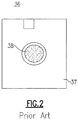
FIG. 2 is a top plan view of a known thin film analytical test element used in the automated clinical analyzer ofFig. 1 ; -
FIG. 3 is a top plan view of a known lateral flow assay device; -
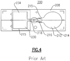
FIG. 4 depicts a top plan view of another known lateral flow assay device; -
FIG. 5 is a top plan view of a lateral flow assay device made in accordance with an exemplary embodiment; -
FIG. 6 is a top plan view of an automated clinical analyzer that is configured to interchangeably utilize both lateral flow assay devices and thin film analytical slide test elements; -
FIG. 7 depicts a partial front perspective view of the automated clinical analyzer ofFig. 6 and more specifically the incubator assembly thereof; -
FIG. 8 is an enlarged top view of the automated clinical analyzer ofFigs. 6 and7 , depicting the loading/staging of a lateral flow assay device for use therein; -
FIG. 9 is an enlarged top view of a portion of the automated clinical analyzer ofFigs. 6-8 , illustrating the metering of sample onto a lateral flow assay device at a dispensing station of the analyzer; -
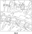
FIG. 10 illustrates an enlarged top view of a portion of the automated clinical analyzer ofFigs. 6-9 , depicting the loading of a lateral flow assay device into an outer ring of the incubator assembly; -
FIG. 11 illustrates another enlarged top view of a portion of the automated clinical analyzer ofFigs. 6-10 , depicting the movement of the lateral flow assay device from the outer ring depicted inFig. 10 to an inner ring of the incubator assembly; -
FIG. 12 illustrates the loading of the lateral flow assay device from the incubator assembly to a testing station of the automated clinical analyzer; -
FIG. 13 is an enlarged version ofFig. 12 , illustrating the alignment of the detection/testing instrument of the automated clinical analyzer relative to the lateral flow assay device; -
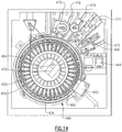
FIG. 14 is a top view of a portion of another automated clinical analyzer, including an incubator assembly made in accordance with another exemplary embodiment; -
FIG. 15 is a top view of a portion of yet another automated clinical analyzer, and particularly another alternative incubator assembly design; and -
FIG. 16 is a partial top perspective view of a wash operation in an automated clinical analyzer involving a lateral flow assay device and in accordance with another embodiment. - The following exemplary embodiment relates to the configuration and design of at least one lateral flow assay device for use in a mainframe automated clinical analyzer. More specifically, this particular embodiment describes the enablement of a plurality of lateral flow assay devices in conjunction with an automated clinical analyzer that is typically configured to receive and process dry slide analytical test elements, a lateral flow assay device that can be used in an automated clinical analyzer and a related method involving interchangeable use of dry slide test elements and lateral flow assay devices in an automated clinical analyzer. It should be noted, however, that this description is intended to be exemplary of the incorporation of certain lateral flow assay devices into an automated clinical analyzer and/or a point-of-care (POC) analyzer. To that end, it will be readily apparent to one of sufficient skill that the inventive concepts herein described are equally applicable to a myriad of other lateral flow assay device designs and use in various other types of automated, as well as POC diagnostic clinical analyzers. Still further, the automated clinical analyzers described herein can be configured, for example, to handle lateral flow assay devices without requiring the separate inclusion of dry slide analytical elements as a stand-alone assembly and alternatively to include other analytical systems in addition to those for the handling of lateral flow assay devices, as described herein, such as a conventional wet chemistry analytical system.
- It should further be noted that the accompanying drawings are not necessarily presented to scale and therefore no narrowing interpretation should be made in terms of dimensions depicted.
- In terms of defining certain of the terms that follow, the term "analyte" is used as a synonym of the term "marker" and intended to minimally encompass any chemical or biological substance that is measured quantitatively or qualitatively and can include small molecules, proteins, antibodies, DNA, RNA, nucleic acids, virus components or intact viruses, bacteria components or intact bacteria, cellular components or intact cells and complexes and derivatives thereof.
- As used in this specification and the appended claims, the singular forms "a", "an" and "the" are intended to further include plural referents unless the context clearly dictates otherwise.
- The term "about" as used in connection with a numerical value throughout the description and the claims denotes an interval of accuracy, familiar and acceptable to a person skilled in the art. The interval governing this term is preferably ± 10 %.
- The term "sample" herein means a volume of a liquid, solution or suspension, intended to be subjected to qualitative or quantitative determination of any of its properties, such as the presence or absence of a component, the concentration of a component, etc. Typical samples in the context of the present invention as described herein are human or animal bodily fluids such as blood, plasma, serum, lymph, urine, saliva, semen, amniotic fluid, gastric fluid, phlegm, sputum, mucus, tears, stool, etc. Other types of samples are derived from human or animal tissue samples where the tissue sample has been processed into a liquid, solution, or suspension to reveal particular tissue components for examination. The embodiments of the present invention are applicable to all bodily samples, but preferably to samples of whole blood, urine or sputum.
- The term "lateral flow assay device" as discussed herein refers to any device that receives fluid, such as sample, and includes a laterally disposed fluid transport or flow path along which various stations or sites are provided for supporting various reagents, filters and the like through which sample traverses under the influence of capillary or other applied forces.
- The terms "automated clinical analyzer", "clinical diagnostic apparatus" or "clinical analyzer" as discussed herein, refer to any apparatus enabling the scheduling and processing of various analytical test elements, such as thin-film or "dry slide" test elements and/or lateral flow assay devices, as discussed herein and in which a plurality of test elements can be initially loaded for processing. This apparatus further includes a plurality of components/systems configured for loading, incubating and testing/evaluating a plurality of analytical test elements in automated or semi-automated fashion and in which test elements are automatically dispensed from at least one contained storage supply, such as a cartridge, without user intervention. Clinical diagnostic apparatus as defined herein can further include desktop and point of care (POC) type devices, as opposed to mainframe versions.
- The terms "zone", "area" and "site" are used in the context of this description, examples and claims to define parts of the fluid flow path on a substrate, either in prior art devices or in at least one device according to an embodiment of the invention.
- The term "reaction" is used to define any reaction, which takes place between components of a sample and at least one reagent or reagents on or in the substrate, or between two or more components present in the sample. The term "reaction" is in particular used to define the reaction, taking place between an analyte and a reagent as part of the qualitative or quantitative determination of the analyte.
- The terms "substrate" or "support" refers to the carrier or matrix to which a sample is added, and on or in which the determination is performed, or where the reaction between analyte and reagent takes place.
- Prior to discussing the inventive concepts, certain background is first provided with reference to
Fig. 1 depicting one version of a known integrated or "combinational" automatedclinical analyzer 10. By "combinational", what is meant is that the analyzer is equipped to handle conventional immunoassays or chemistry assays, as well as testing of thin film analytical test elements. Thisexemplary analyzer 10 is defined by a housing or enclosure (not shown) that is appropriately sized to retain a plurality of components that are now briefly described. Generally, theanalyzer 10 is configured to commonly retain two separate analytical systems that can be used in tandem; namely, a so-called "dry" chemistryanalytical system 80 and a "wet" (immunoassay-based or chemistry-based) analytical module orsystem 90. - More specifically, the
analyzer 10 includes a primary sample supply orhandler 14 that retains a plurality ofprimary sample containers 18 and aprimary metering mechanism 22 that includes ametering transport rail 26 and ametering truck 30 which is movable along the transport rail between a number of stations. Among the stations disposed along the linear travel path of themetering mechanism 22 are ametering station 68 for afirst incubator assembly 34. At thismetering station 68, a quantity of sample can be deposited onto a dry slide (thin film)element 36 which is then shuttled into thefirst incubator assembly 34. Thetest element 36 is further shown inFig. 2 and is defined by asubstrate 37 having aporous center section 38 defining a multi-layered reaction area that receives a volume of sample, which is aspirated thereupon using a pipette or other dispensing apparatus. Specifics relating to this latter test component are described in greater detail inU.S. Patent No. 3,992,158 to Przbylowicz et al. - The
first incubator assembly 34 includes at least one read station (not shown) including a testing device for correlated analyte detection, such as a reflectometer or an electrometer (not shown). According to this version, an auxiliarysample handling apparatus 40 is disposed in relation to thefirst incubator assembly 34 and includes a tip supply for maintaining a plurality of disposable metering tips. The foregoing comprises the dry chemistryanalytical system 80 of thisanalyzer 10. - Still referring to
Fig. 1 , asecondary metering mechanism 42 includes a secondary metering mechanism having ametering truck 44 similar to themetering truck 30 for thedry chemistry portion 80 of theanalyzer 10, which is also movable along themetering transport rail 26, areagent wheel 52 which includes a plurality of reagent containers or packs 54 containing at least one reagent, asecond incubator assembly 56, amicro-tip supply 60, and areaction vessel conveyor 58 carrying a plurality ofreaction vessels 64. Each of the foregoing components define thewet chemistry portion 90 of theanalyzer 10. - As noted, each of the dry and
wet chemistry systems sample handling apparatus 40. Themovable truck 30 of theprimary metering mechanism 22 is shuttled along themetering transport rail 26 to a predetermined station that enables a tip to be picked up using the probocsis thereof in a commonly known manner. Themovable truck 30 is then driven to theprimary sample handler 14 and the probocsis and attached metering tip are lowered into an alignedsample receptacle 18. A predetermined volume of sample is drawn under vacuum and aspirated into the confines of the metering tip. Themetering truck 30 carrying the metering tip with aspirated sample is then shuttled along thetransport rail 26 from theprimary sample handler 14 to themetering station 68. At thisstation 68, a dry slide (thin film)analytical test element 36 has been positioned as discharged from a vertically disposed storage cartridge (not shown) carrying a plurality of these elements. - A volumetric portion of the sample contained within the metering tip is then dispensed onto the dry
slide test element 36, which is arranged to be loaded usingpusher blade assembly 39, into thefirst incubator assembly 34. The sample is metered onto, for example, a potentiometric or colorimetric slide element which is then incubated for a predetermined time, in which the provided test instrumentation determines the results (analyte concentration, detection, etc.). Additional details relating to the incubation and testing of dry slide elements are described, for example, inU.S. Patent No. 4,296,069 . - Sequentially and following the above-noted metering step according to this known version, the metering tip is then advanced to the auxiliary
sample handling apparatus 40. At thisapparatus 40, the dispense end of the metering tip is heat-sealed enabling the metering tip to thereafter be used as an auxiliary sample container for use with thewet chemistry system 90. The sealed metering tip is retained within a housing in relation to thesecondary metering mechanism 42 wherein a plurality of sealed metering tips are stored. - As to the conduction of "wet" assays and if sample is required, a micro-tip is picked up from the
micro-tip supply 60 by thesecondary metering mechanism 42 using themetering truck 44 and the attached proboscis (not shown). The micro-tip is sized to fit within the confines of a sealed metering tip serving as an auxiliary sample retainer. Themetering truck 44 is then moved into position relative to theauxiliary sample supply 40. Once sample has been aspirated from the auxiliary sample retainer (sealed metering tip), themovable metering truck 44 is located in relation to areaction vessel 64, and specifically a reaction chamber thereof for dispensing of the sample. An exemplary reaction vessel is described inU.S. Patent Application Publication No. 2003/0003591 A1 . Once sample has been dispensed into a reaction chamber of thereaction vessel 64, the micro-tip can be discarded by the apparatus. - Reagents for the conducted wet assay are brought to the
reaction vessel 64 from the reagent container 54, which is rotated to a predetermined aspiration position by thereagent wheel 52 that retains the separate reagent containers 54 in a refrigerated state. An unsealed metering tip is picked up using the probocsis by themovable metering truck 44 of thesecondary metering mechanism 42. Themovable truck 44 is then shuttled to an aspiration position of thereagent wheel 52. In this position, reagent fluid is aspirated into the attached metering tip. Themetering truck 44 is then shuttled to a metering position relative to thereaction vessel 64 and reagent is dispensed into the reaction chamber. The tip can actually be fitted within the reaction chamber containing the sample to aid in mixing of reagent and sample, if needed. The metering tip is subsequently disposed of following its use. Additional quantities of other reagents or other fluids (e.g., calibration, dilution, wash, etc.) are similarly handled using disposable metering tips for conducting the assay, which is subsequently incubated in theincubator 56 including a read station (not shown) having a detection instrument disposed therein, such as a spectrophotometer, for obtaining results. Additional background and detail in regard to integrated or so-called "combinational" automated clinical analyzers, such as those described according toFig. 1 and variants thereof, is provided for example inU.S. Patent Nos. 7,250,303 and7,855,084 B2 . - With the foregoing background and now referring to
Fig. 3 , a known exemplary lateralflow assay device 100 for purposes of this embodiment is herein described. The lateralflow assay device 100 in accordance with this embodiment is defined by aplanar substrate 108 preferably made from a suitable non-porous material, though porous materials can be alternatively provided, as discussed infra. A plurality ofprojections 112, such as micropillars, extend upwardly from a top or upper surface of thesubstrate 108 the projections preferably forming the defined area shown by the borderingline 115. In other versions and as discussed in a later section, flow channels can be cut into the surface of the substrate in which the projections extend from a bottom surface of the channel. According to this particular assay device design, asample addition area 118 at one side of thedevice 100 extends to anadjacent reagent zone 120 disposed in relation to the sample addition area, further extending at least onedetection area 124 and awicking area 130. - A defined fluid flow path is created from the
sample addition area 118 extending to thewicking area 130 that is at least partially open. In another embodiment, the flow path is entirely open. By "open" what is meant is that there is no lid or cover at a capillary distance. Thus a lid, if present as a physical protection for the flow path, does not contribute to the capillary flow in the flow path. An open lateral flow path is described, for example, in the following published applications:WO 2003/103835 ,WO 2005/089082 ;WO 2005/118139 ;WO 2006/137785 ; andWO 2007/149042 . The extendingprojections 112 have a height (H), diameter (D) and a distance or distances between the projections (t1, t2) such, that lateral capillary flow of an applied fluid, such as plasma, preferably human plasma, in the zone is achieved. These relationships are discussed inUS 2006/0285996 . In addition to optimizing the above-mentioned height, diameter and a distance or distances between the projections, theprojections 112 may be given a desired chemical, biological or physical functionality, e.g. by modifying the surface of the projections for purposes, for example, of the reagent area(s) and detection area(s) of the device. In one embodiment, the projections have a height in the interval of about 15 to about 150 µm, preferably about 30 to about 100 µm, a diameter of about 10 to about 160 µm, preferably 40 to about 100 µm, and a gap or gaps between the projections of about 3 to about 200 µm, preferably 5 to 50 µm or 10 to about 50 µm from each other. The flow channel between thesample addition area 118 and thewicking area 130 may have a length of about 5 to about 500 mm, preferably about 10 to about 100 mm, and a width of about 0.3 to about 10 mm, preferably about 0.3 to about 3 mm, preferably about 0.5 to 1.5, and preferably about 0.5 to 1.2 mm. Theprojections 112 according to this device design are substantially cylindrical in configuration and cross section. However, their specific design can easily be varied to those of different shapes (e.g., rhombic, hexagonal, etc) and sizes to augment flow, as well as to filter materials. - Referring to
Fig. 4 , there is depicted another known lateralflow assay device 200 is defined by anon-porous substrate 208 having a sample addition area orzone 214 disposed at one end that forms a portion of a lateral fluid flow path extending through areagent zone 216 containing a detection conjugate or other reagent and further extending to adetection zone 218 and further extending to awicking zone 230 defining the opposite end of the fluid flow path. Optionally, the lateral fluid flow path may also include additional separate zones containing reagents or detection conjugate, as well other zones, areas or sites along this path that can be utilized used for washing of the sample and any bound or unbound components thereof. - According to this particular embodiment, a plurality of
projections 212 extend upwardly from the top surface of thesubstrate 208 substantially defining the active portions defined within the borderingline 215 of this device wherein the projections are specifically designed dimensionally in terms of their height and diameters, as well as with relative interpillar spacings, so as to solely promote spontaneous lateral capillary flow along the defined fluid flow path between thesample addition area 214 and thewicking zone 230. As discussed infra, this design is referred to as an "open" system or device, meaning that side walls and a cover are not necessarily required to assist in the creation of capillary force. It will further be noted that a cover or lid can be optionally included; for example, a cover can be added to the device as needed, the cover being spaced in relation to theprojections 212 so as not contribute to the lateral capillary flow of a sample liquid. It is has been determined, however, that the addition of a hydrophilic foil orlayer 234 directly onto at least a portion of thewicking area 230 alone does contribute to the overall flow rate (process time) of an aspirated sample. - An exemplary design of another lateral
flow assay device 300, which is herein described for purposes of the present invention is provided inFig. 5 . Though thisparticular assay device 300 is referred to throughout the remainder of this description in terms of an exemplary embodiment, it will be readily apparent that other device designs and possible variants of these designs could also be similarly configured for interrelationships in a clinical analyzer, as herein discussed. Theexemplary assay device 300 is defined by asubstrate 304 that includes a liquidsample addition zone 308 that receives sample from a liquid dispenser. The sample is typically deposited onto the top of the zone. Thesample addition zone 308 is capable of transporting the liquid sample from the point when the sample is deposited to areagent zone 312, through an optional filter and reagent addition zone (not shown), preferably through capillary flow. The capillary flow inducing structure can include porous materials, such as nitrocellulose, or preferably through projections, such as micro-pillars as previously described. A filler material (not shown) can be also be placed within thesample addition zone 308 to filter particulates from the sample or to filter blood cells from blood so that plasma can travel through thedevice 300. - Located between the
sample addition zone 308 and adetection zone 318 is areagent zone 312. Thereagent zone 312 can include reagent(s) integrated into this analytical element and are generally reagents useful in the reaction --- binding partners such as antibodies or antigens for immunoassays, substrates for enzyme assays, probes for molecular diagnostic assays, or are auxiliary materials such as materials that stabilize the integrated reagents, materials that suppress interfering reactions, and the like. Generally, one of the reagents useful in the reaction bears a detectable signal as discussed herein. In some cases, the reagents may react with the analyte directly or through a cascade of reactions to form a detectable signal such as a colored or fluorescent molecule. In one preferred embodiment, the reagent zone includes conjugate material. The term "conjugate" means any moiety bearing both a detection element and a binding partner. - For purposes of this description, a detection element is an agent which is detectable with respect to its physical distribution and/or the intensity of the signal it delivers, such as but not limited to luminescent molecules (e.g., fluorescent agents, phosphorescent agents, chemiluminescent agents, bioluminescent agents and the like), colored molecules, molecules producing colors upon reaction, enzymes, radioisotopes, ligands exhibiting specific binding and the like. The detection element also referred to as a label is preferably chosen from chromophores, fluorophores, radioactive labels and enzymes. Suitable labels are available from commercial suppliers, providing a wide range of dyes for the labeling of antibodies, proteins and nucleic acids. There are, for example, fluorophores spanning practically the entire visible and infrared spectrum. Suitable fluorescent or phosphorescent labels include for instance, but are not limited to, fluoroceins, Cy3, Cy5 and the like. Suitable chemoluminescent labels include but are not limited to luminal, cyalume and the like.
- Similarly, radioactive labels are commercially available, or detection elements can be synthesized so that they incorporate a radioactive label. Suitable radioactive labels include but are not limited to radioactive iodine and phosphorus; e.g., 125I and 32P.
- Suitable enzymatic labels include but are not limited to horseradish peroxidase, beta-galactosidase, luciferase, alkaline phosphatase and the like. Two labels are "distinguishable" when they can be individually detected and preferably quantified simultaneously, without significantly disturbing, interfering or quenching each other. Two or more labels may be used, for example, when multiple analytes or markers are being detected.
- The binding partner is a material that can form a complex that can be used to determine the presence of or an amount of an analyte. For example, in a "sandwich" assay, the binding partner in the conjugate can form a complex including the analyte and the conjugate and that complex can further bind to another binding partner, also called a capture element, integrated into the detection zone. In a competitive immunoassay, the analyte will interfere with binding of the binding partner in the conjugate to another binding partner, also called a capture element, integrated into the detection zone. Example binding partners included in conjugates include antibodies, antigens, analyte or analyte-mimics, protein, etc.
- Optionally located in the fluid flow path, before or after the
reagent zone 312 and before thedetection zone 318 is a reagent addition zone (not shown). The reagent addition zone can allow the addition of a reagent externally from thedevice 300. For example, the reagent addition zone may be used to add an interrupting reagent that can be used to wash the sample and other unbound components present in the fluid flow path into awicking zone 324. In a preferred embodiment, the reagent addition zone is located after thereagent zone 312. - Downstream from the
reagent zone 312 and along the folded fluid path defined by theflow channel 317 is thedetection zone 318 which is in fluid communication with the reagent zone. Thedetection zone 318 may include projections or micropillars, such as those as described above. Also as noted above, these projections are preferably integrally molded into the substrate from an optical plastic material such as Zeonor, such through an injection molding or embossing process. The width in the flow path in thedetection zone 318 is typically on the order of 0.5 - 4mm and preferably on the order of about 2mm, although others can be prepared on the order of about 1mm, provided sufficient signal for a suitable detection instrument, such as a fluorimeter, can be read even if the reagent plume does not cover the entire width of the detection zone. - The
detection zone 318 is where any detectable signal can be read. In a preferred embodiment and attached to the projections in thedetection zone 318 are capture elements. The capture elements can hold binding partners for the conjugate or complexes containing the conjugate, as described above. For example, if the analyte is a specific protein, the conjugate may be an antibody that will specifically bind that protein to a detection element such as fluorescence probe. The capture element could then be another antibody that also specifically binds to that protein. In another example, if the marker or analyte is DNA, the capture molecule can be, but is not limited to, synthetic oligonucleotides, analogues, thereof, or specific antibodies. Other suitable capture elements include antibodies, antibody fragments, aptamers, and nucleic acid sequences, specific for the analyte to be detected. A non-limiting example of a suitable capture element is a molecule that bears avidin functionality that would bind to a conjugate containing a biotin functionality. The detection zone can include multiple detection zones. The multiple detection zones can be used assays that include one or more markers. In the event of multiple detection zones, the capture elements can include multiple capture elements, such as first and second capture elements. The conjugate can be pre-deposited on the assay device, such as by coating in the reagent zone. Similarly, the capture elements can be pre-deposited on the assay device on the detection zone. Preferably, both the detection and capture elements are pre-deposited on the assay device, or on the reaction zone and detection zone, respectively. - Capture elements, such as antibodies in the detection zone (such as by coating); and a labeled conjugate material that is also capable of participating in reactions that will enable determination of a concentration of analyte, are preferably deposited on the device in the reagent zone, wherein the labeled conjugate material carries a label for detection in the detection zone.
- After the sample has been delivered to the
sample addition zone 308, it will encounter thereagent zone 312. After the sample has flowed through and interacted with thereagent zone 312 and optionally the reagent addition zone, the sample and a reagent plume will be contained in the fluid flow. The reagent plume can contain any of the reagent materials that have been dissolved in thereaction zone 312 or those added through the optional reagent addition zone. The reagent plume can include the conjugate having both the detection element and binding partner, in which case it is often referred to as a conjugate plume. - Downstream from the
detection zone 318 along the folded fluid path is thewicking zone 324 in fluid communication with the detection zone. Thewicking zone 324 is an area of theassay device 300 with the capacity of receiving liquid sample and any other material in the flow path, e.g. unbound reagents, wash fluids, etc. Thewicking zone 324 provides a capillary force to continue moving the liquid sample through and out the detection zone of the assay device. The wicking zone can include a porous material such as nitrocellulose or preferably is a non-porous structure defined by projections as described previously. The wicking zone can further include non-capillary fluid driving means, such as using evaporative heating or a pump. Further details of wicking zones as used in lateral now assay devices according to the present invention are found in patent publicationsUS 2005/0042766 andUS 2006/0239859 . - Preferably, the entirety of the flow path including the sample addition zone, the detection zone and the wicking zone includes projections substantially vertical in relation to the substrate, and having a height, diameter and reciprocal spacing capable of creating lateral capillary flow of the sample in the flow path.
- Components of the lateral flow assay devices (i.e., a physical structure of the device whether or not a discrete piece from other parts of the device) described herein can be prepared from copolymers, blends, laminates, metallized foils, metallized films or metals. Alternatively, device components can be prepared from copolymers, blends, laminates, metallized foils, metallized films or metals deposited one of the following materials: polyolefins, polyesters, styrene containing polymers, polycarbonate, acrylic polymers, chlorine containing polymers, acetal homopolymers and copolymers, cellulosics and their esters, cellulose nitrate, fluorine containing polymers, polyamides, polyimides, polymethylmethacrylates, sulfur containing polymers, polyurethanes, silicon containing polymers, glass, and ceramic materials. Alternatively, components of the device can be made with a plastic, elastomer, latex, silicon chip, or metal; the elastomer can comprise polyethylene, polypropylene, polystyrene, polyacrylates, silicon elastomers, or latex. Alternatively, components of the device can be prepared from latex, polystyrene latex or hydrophobic polymers; the hydrophobic polymer can comprise polypropylene, polyethylene, or polyester. Alternatively, components of the device can comprise TEFLON®, polystyrene, polyacrylate, or polycarbonate. Alternatively, device components are made from plastics which are capable of being embossed, milled or injection molded or from surfaces of copper, silver and gold films upon which may be adsorbed various long chain alkanethiols. The structures of plastic which are capable of being milled or injection molded can comprise a polystyrene, a polycarbonate, or a polyacrylate. In a particularly preferred embodiment, the lateral flow assay devices are injection molded from a cyclo olefin polymer, such as those sold under the name Zeonor®. Preferred injection molding techniques are described in
U.S. Patent Nos. 6,372,542 ,6,811,736 ,6,884,370 , and6,733,682 . - The defined flow path of the assay devices described herein, including
device 300, can include open or closed paths, grooves, and capillaries. Preferably the flow path comprises a lateral flow path of adjacent projections, having a size, shape and mutual spacing such that capillary flow is sustained through the flow path. In one embodiment, the flow path is in a channel within the substrate having a bottom surface and side walls. In this embodiment, the projections protrude from the bottom surface of the channel. The side walls may or may not contribute to the capillary action of the liquid. If the sidewalls do not contribute to the capillary action of the liquid, then a gap can be provided between the outermost projections and the sidewalls to keep the liquid contained in the flow path defined by the projections. Preferably, the reagent that is used in thereaction zones 312 and the capture members or detection agent used in thedetection zones 318 is bound directly to the exterior surface of the projections used in the herein describedassay device 300. - Referring to
Fig. 6 , an automatedclinical analyzer 400 is herein described in accordance with one exemplary embodiment, the exemplary analyzer being configured for interchangeably handling and processing bothanalytical test elements 36, such as those inFig. 2 and lateralflow assay devices 300, such as those depicted inFig. 5 . More specifically, theclinical analyzer 400 is defined by a housing orenclosure 408 that retains a plurality of components. These components include asample supply 414 that retains a plurality of sample receptacles ortest tubes 416 incarrier members 418 that are moved along anendless belt 420 over an ovate transport path. Ametering mechanism 424 includes ametering rail 427 aligned with thesample supply 414 and retaining a translatablymovable metering head 429 having an attachedproboscis 430,Fig. 9 , that is vertically movable to aspirate a predetermined quantity of sample from one of thesample receptacles 416 at an aligned aspiration station. - An
incubator assembly 450 is disposed in relation to themetering rail 427, including a pair of concentric rotor assemblies that are independently rotatable about a center axis, such as through abelt drive 453. Theincubator assembly 450 according to this embodiment is defined by a plurality of independentlyrotatable rings flow assay device 300, as discussed herein. According to this embodiment, a predetermined number (N) receiving slots are provided wherein the incubator housing further includes a cover (not shown). Anelectrometer 462 is disposed adjacent one of therings 454 of theincubator 450 and a colorimeter (not shown) is disposed beneath another of the independentlyrotatable rings 459 to enable testing of thin filmanalytical test elements 36,Fig. 2 , and permit interchangeability therein, as needed. Theincubator 450 can be further equipped to permit immunorate testing of thin filmanalytical test elements 36,Fig. 2 , by movement of the slide elements to the interior of theinner ring 459. A plurality of reciprocatingpusher blade assemblies analytical test elements 36 to be radially moved between therotatable rings metering station 466 is disposed in relation to the exterior of the incubator housing adjacent a stagingstation 468 in which test elements are positioned prior to metering and loading into theincubator 450 for processing. Ashuttle mechanism 469 is disposed for moving test elements discharged from a storage cartridge (not shown) disposed in asupply slot 444 to the stagingstation 468. - One of the reciprocating
pusher blade assemblies 474 is disposed to push at least onetest element 36,Fig. 2 , from the stagingstation 468 to themetering station 466 to receive a quantity of sample and from the metering station to one of therings sample supply 414,metering mechanism 424 andincubator assembly 459, each of them are as described or substantially similar to those described in greater detail inU.S. Patent Nos. 7,250,303 and7,855,084B2 , and in which the above noted features specific to theincubator assembly 450 are further described in greater detail inU.S. Patent No. 7,312,084 and in which the pusher blade assemblies are described in general inUS Patent No. 5,093,342 . In this regard, the system described to this point is substantially similar to that previously described in terms of the dry chemistry "side" of the combinational analyzer described in the above-referenced 7,250,303 patent. - In this regard, the lateral
flow assay devices 300 are sized substantially to be equivalent to that of the previously known analytical thinfilm test elements 36,Fig. 2 . The herein described automatedclinical analyzer 400 is further configured to enhance capability of same to interchangeably incorporate and process lateralflow assay devices 300 in addition to thetest elements 36, as discussed herein. Alternatively, however, the automated clinical analyzer can be configured to separately incorporate lateral flow assay devices and thin film analytical test elements or operate as a stand-alone device that solely receives and processes lateral flow assay devices. Alternatively and according to another version, the apparatus can further be equipped with a wet chemistry analytical system, as described inU.S. Patent No. 7,250,303 . Combinations of each described variant are also contemplated within the inventive aspects discussed herein. - According to this exemplary embodiment, a detection instrument capable of detecting the perceivable signal of the
detection area 318 of the lateralflow assay device 300, and more specifically afluorimeter 470, is disposed substantially in the center of the incubator housing adjacent theinnermost ring 454 thereof and aligned to linearly scan lateralflow assay devices 300 that are caused to be positioned within anadjacent test station 480,Fig. 12 . Thefluorimeter 470 is equipped with alaser 484 used to optically scan the devices one at a time along a portion of the fluid flow path and more preferably along thelinear portion 317 of the flow channel separating thesample addition zone 308 and thewicking zone 324 and preferably containing thedetection zone 318 and depending on the construction of this element, at least onereaction zone 312. This specific positioning of the incubator is useful in that the reciprocatingpusher blade assembly 474 was previously configured to advance a dryslide test element 36 into an IR wash module previously disposed in the center of the incubator. For purposes of this embodiment, the wash module of the existing analyzer is removed with thefluorimeter 470 assuming this location. It will be readily apparent that there are various alternative positions that the above-noted detection instrument could assume. Certain of these alternatives are discussed in a later portion of this description. - The test elements/
assay devices analytical test element 36 ofFig. 2 and the lateralflow assay device 300 ofFig. 5 are substantially identical and therefore interchangeability is provided in terms of accommodation throughout processing. Each storage cartridge is disposed within at least one vertically aligned storage slot of theanalyzer 400. According to this specific embodiment, a pair ofparallel storage slots 444 are provided. - As noted, the processing of dry-slide
analytical test elements 36,Fig. 2 , is generally known and as previously described herein. The following describes the incorporation of lateralflow assay devices 300, which are dispensed one at a time from a lower opening of a storage cartridge (not shown) as retained within at least one of thesupply slots 444. Thesedevices 300 are shuttled using themechanism 469 or similar means into the stagingstation 468. From this position, the reciprocatingpusher blade assembly 474 engages a side or lateral edge of thedevice 300 in order to translatably move same. The stagingstation 468 according to this embodiment includes a pair of axially disposed slots enabling a pair ofassay devices 300 from respective storage cartridges to be retained in side by side relation and in which the reciprocatingpusher blade assembly 474 is configured to advance theassay devices 300 radially to themetering station 466, the latter having at least one opening sized to receive the proboscis and attached metering tip of themetering head 429, which can be lowered therein. - In terms of overall operation, at least one storage cartridge (not shown) can be loaded with thin film
analytical test elements 36,Fig. 2 , while at least one other storage cartridge (not shown) can be filled with a predetermined quantity of lateralflow assay devices 300, such as those previously described herein. - Referring to
Figs. 7-13 , one exemplary sequence is herein described involving the testing of at least one lateralflow assay device 300 in theclinical analyzer 400. First and referring toFig. 7 , a pair of storage cartridges (not shown) are loaded into each of thesupply slots 444 of theanalyzer 400, at least one storage cartridge containing a plurality of lateralflow assay devices 300. If selected and according toFig. 8 , a lateralflow assay device 300 can be removed from the lower end of a retained storage cartridge and shuttled laterally into a slot of the stagingstation 468 sized to retain the device, the slot being adjacent the dispensing ormetering station 466 of theanalyzer 400. From this position and referring toFig. 9 , the lateralflow assay device 300 is further shuttled using thepusher blade assembly 474,Fig. 6 , into themetering station 466 such that the lateral flow assay device is positioned within the confines of a metering block and in which thesample addition zone 308 is positioned directly beneath a metering opening. In parallel, theanalyzer 400 has already caused themetering truck 44 to pick up a disposable metering tip from a tip supply of the analyzer for attachment onto the proboscis and aspirated a quantity of sample from one of thetest receptacles 416 at thesample supply 414. Theproboscis 430, partially shown, is moved into position along themetering rail 427,Fig. 6 , according to this embodiment and lowered into the metering opening. A predetermined volume of sample (10-15 microliters) is then deposited onto thesample addition area 308 of the lateralflow assay device 300. - Based on the design of the instant lateral
flow assay device 300, the application of sample to thesample addition area 308 and particularly the upwardly extending projections spontaneously induces lateral capillary flow of the dispensed patient sample along the defined flow path. According to this element design, sample flows outwardly through an optional filter and through the defined projections of thesample addition area 308 under the capillary force created along the flow path extending through thereaction zone 312. As the fluid sample first engages the detection conjugate or other reagent, the sample begins to dissolve this conjugate, thereby creating a perceivable plume indicative of the process flow, such as a conjugate plume, as previously discussed. The sample and related material advance through the optional reaction adding zone and the definedflow channel 317 towards thedetection zone 318 and thewicking zone 324 of theassay device 300. The fluid sample continues to flow along the flow path through the channels defined therein and along each intermediate reaction area against reactants or other moieties that are bound or otherwise attached to the projections, enabling a reaction to take place, which can be detected along a defined linear path by thefluorimeter 470 or other optical or suitable test/detection instrument, as discussed herein, and in which the sample continues to advance to thewicking area 324, the latter being sized to receive the volume of fluid dispensed. - As reaction(s) are occurring based on the addition of sample to the lateral
flow assay device 300 and referring toFig. 10 , the lateral flow assay device can be radially positioned from themetering station 466 to a slot provided on theouter ring 459 of theincubator 450 after a predetermined dwell time using thepusher blade assembly 474. Following a few cycles (rotations) and as shown inFig. 11 , the lateralflow assay device 300 can be further advanced into theinner ring 454 of theincubator 450 using one of the plurality of adjacent reciprocatingpusher blade assemblies 476 that is disposed about the outer periphery of theincubator assembly 450. The lateralflow assay device 300 can further be radially advanced within theinner ring 459 to an inner radial position, depending on the number and types of tests to be performed on theassay device 300. Following a predetermined incubation time (e.g. ,5 minutes, 10 minutes, etc.) and referring toFigs. 12 and13 , thepusher blade assembly 474 can further cause the lateralflow assay device 300 to be pushed radially inward and into thetest station 480 adjacent thescanning laser 484 of thefluorimeter 470. Once situated in this station, theassay device 300 is aligned in order to permit sequential optical scanning of the contained sample and reactants along aportion 317 of the flow path that aligns thedetection area 318 of theassay device 300 with thescanning laser 484 of thefluorimeter 470 allowing analytical test or detection results can be therefore be provided in real time. In the present embodiment, thescanning laser 484 of thefluorimeter 470 takes fluorescence measurements over the reaction or detection zone in which the results are available or further analysis by prediction algorithms processed in an on-board computer. Following scanning by thefluorimeter 470, the lateralflow assay devices 300 are caused to drop one at a time through a vertically disposed exit chute (not shown) of theincubator assembly 450 and are discarded. - Other variations are possible within the framework of these described concepts. For example and referring to
Fig. 14 in which similar parts are labeled with the same reference numerals, theincubator assembly 488 can be alternatively constructed to include a separateinterior ring 490 having a predetermined number of retaining stations or slots with appropriate temperature and humidity controls, this latter ring being used specifically for lateral flow assay devices such as those previously described or other designs, for example, those having different form factors as compared to conventional thin film slideanalytical test elements 36,Fig. 2 . The assay devices can be directly loaded into theinterior ring 490 or initially loaded using the pusher blade assembly into theouter ring 454 and subsequently advanced radially inwardly using any of thepusher blade assemblies pusher blade assembly 474 can be utilized to advance assay devices from the interior ring to the readingstation 480 prior to having optical or other detection measurements made thereon. - Still other variations are also contemplated herein. For example and referring to
Fig. 15 , a separate ring and/or the testing/detection instrument (i.e., fluorimeter) can either be planar to the inner andouter rings incubator 504 or can, for example, be disposed either above or below the horizontal plane defined thereby. In this construction, for example, an elevator assembly (not shown) can be included that permits the loading and unloading of assay devices, as needed. One exemplary elevator design as used in an incubator with portions defined on different horizontal planes is described inU.S. Patent No. 5,419,871 to Muszak et al. - Still other variations are possible employing the concepts described herein. For example, a fluorimeter or other suitable detection/reading instrument can be disposed relative to an already existing ring of the incubator assembly. Other similar variations are herein contemplated herein.
- As noted, the herein described lateral flow assay devices can be designed to include features to enable additional processing, such as at least one reaction adding zone. Referring to
Fig. 16 and according to one exemplary version, a lateral flow assay device may optionally include at least one wash area adjacent the sample addition area of the device, which can be used, for example in the conduction of assays involving whole blood as a sample. Ametering head 520 can be lowered by known means to add wash fluid to a reagent adding zone of a suitable lateral flow assay device. - It will be appreciated that numerous other modifications and variations will be readily apparent to one of sufficient skill in the field that encompass the invention as defined by the following listed claims. For example, the herein described lateral flow assay devices can also be used in conjunction with point-of-care (POC) analyzers or other apparatus. According to at least one version, a lateral flow assay device could be interchangeably used in both POC and mainframe clinical analyzer applications.
Claims (9)
- An automated analyzer (400) comprising:first and second storage cartridges that retain a first plurality of analytical test elements and a second plurality of analytical test elements, respectively, in which the first plurality of analytical test elements comprise thin-film slide elements (36) having a sample addition area and the second plurality of analytical test elements comprise lateral flow assay devices (100, 200, 300), each of the lateral flow assay devices comprising a planar support having at least one sample addition area (118, 214, 308), at least one reaction area (120, 216, 312), at least one detection area (124, 218, 318) and a wicking area (130, 230, 324) fluidically interconnected along at least one lateral fluid flow path and in which fluid movement in the lateral flow assay devices occurs under capillary force from the at least one sample addition area to the wicking area, and wherein each of the plurality of lateral flow assay devices has a form factor that enables interchangeability with the thin-film slide element in the automated analyzer;a transfer mechanism (469) that sequentially removes individual analytical test elements from each of the first and second storage cartridges;a metering mechanism (424) that dispenses sample onto a sample addition area of each of the removed analytical test elements from the first and second storage cartridges;at least one incubator assembly (459) having a rotor assembly comprising a plurality of independently rotatable concentric ring members (454, 459) supported for rotation about a center axis and having a plurality of receiving stations individually sized to receive the first plurality and the second plurality of analytical test elements having sample dispensed thereon from the metering mechanism;first and second detection devices disposed and positioned in relation to the at least one incubator assembly to detect test results relative to each of the first plurality and second plurality of analytical test elements; andin which at least one of the at least one incubator assembly interchangeably handles and processes both dry slide analytical test elements and lateral flow assay devices from the first and second storage cartridges.
- The analyzer as recited in claim 1, in which each ring member has a plurality of receiving stations that receives a said analytical test element from the metering mechanism, and in which each of the plurality of concentric rings is configured to interchangeably receive each of said first and second plurality of test elements.
- The analyzer as recited in claim 1, in which at least one said ring member includes receiving stations that handle one of said first and second pluralities of test elements and the another said ring member includes receiving stations to handle the other of said first and second pluralities of test elements.
- The analyzer as recited in claim 1, further including a wet chemistry module that performs immunoassays.
- The analyzer as recited in claim 1, wherein the analyzer is one of a point of care or a mainframe analyzer.
- The analyzer as recited in claim 1, wherein each lateral flow assay device further includes a plurality of projections (112) extending from the support and disposed along at least a portion of the at least one fluid flow path, the projections being dimensionally sized and spaced to induce lateral capillary flow.
- The analyzer as recited in claim 1, in which at least one lateral flow assay device comprises a plurality of reaction areas and is configured for performing multiple assays at one time.
- The analyzer as recited in claim 1, wherein the at least one detection device comprises a fluorometer that is configured to read test results of a lateral flow assay device in the incubator assembly at the detection area thereof.
- The analyzer as recited in claim 6, wherein the projections are substantially vertical and are disposed along substantially the entire fluid flow path of the lateral flow assay device, including the wicking area.
Applications Claiming Priority (3)
| Application Number | Priority Date | Filing Date | Title |
|---|---|---|---|
| US201261658698P | 2012-06-12 | 2012-06-12 | |
| US201361793657P | 2013-03-15 | 2013-03-15 | |
| EP13171542.7A EP2674763B1 (en) | 2012-06-12 | 2013-06-11 | System for processing lateral flow assay devices |
Related Parent Applications (1)
| Application Number | Title | Priority Date | Filing Date |
|---|---|---|---|
| EP13171542.7A Division EP2674763B1 (en) | 2012-06-12 | 2013-06-11 | System for processing lateral flow assay devices |
Publications (2)
| Publication Number | Publication Date |
|---|---|
| EP3594690A1 EP3594690A1 (en) | 2020-01-15 |
| EP3594690B1 true EP3594690B1 (en) | 2021-04-07 |
Family
ID=48578892
Family Applications (2)
| Application Number | Title | Priority Date | Filing Date |
|---|---|---|---|
| EP13171542.7A Active EP2674763B1 (en) | 2012-06-12 | 2013-06-11 | System for processing lateral flow assay devices |
| EP19193656.6A Active EP3594690B1 (en) | 2012-06-12 | 2013-06-11 | System for processing lateral flow assay devices |
Family Applications Before (1)
| Application Number | Title | Priority Date | Filing Date |
|---|---|---|---|
| EP13171542.7A Active EP2674763B1 (en) | 2012-06-12 | 2013-06-11 | System for processing lateral flow assay devices |
Country Status (8)
| Country | Link |
|---|---|
| US (2) | US9389228B2 (en) |
| EP (2) | EP2674763B1 (en) |
| JP (2) | JP6345392B2 (en) |
| CN (1) | CN103480438B (en) |
| BR (1) | BR102013014526A2 (en) |
| CA (1) | CA2818332C (en) |
| ES (2) | ES2758043T3 (en) |
| RU (1) | RU2013126790A (en) |
Families Citing this family (16)
| Publication number | Priority date | Publication date | Assignee | Title |
|---|---|---|---|---|
| EP2778679B1 (en) * | 2013-03-15 | 2017-09-27 | Ortho-Clinical Diagnostics, Inc. | Rotable disk-shaped fluid sample collection device |
| CA2932269C (en) * | 2013-12-06 | 2022-01-25 | Ortho Clinical Diagnostics, Inc. | Assay device having a wash port |
| US10031085B2 (en) | 2014-07-24 | 2018-07-24 | Ortho-Clinical Diagnostics, Inc. | Point of care analytical processing system |
| US10073091B2 (en) | 2014-08-08 | 2018-09-11 | Ortho-Clinical Diagnostics, Inc. | Lateral flow assay device |
| US10071373B2 (en) | 2014-08-08 | 2018-09-11 | Ortho-Clinical Diagnostics, Inc. | Lateral-flow assay device having flow constrictions |
| US11033896B2 (en) | 2014-08-08 | 2021-06-15 | Ortho-Clinical Diagnostics, Inc. | Lateral-flow assay device with filtration flow control |
| US9638685B2 (en) | 2014-09-19 | 2017-05-02 | Tokitae Llc | Flow assay with at least one electrically-actuated fluid flow control valve and related methods |
| US10549273B2 (en) | 2014-09-19 | 2020-02-04 | Tokitae Llc | Flow assay with at least one electrically-actuated fluid flow control valve and related methods |
| WO2016130964A1 (en) | 2015-02-13 | 2016-08-18 | Abbott Laboratories | Decapping and capping apparatus, systems and methods for use in diagnostic analyzers |
| EP3322346B1 (en) | 2015-07-13 | 2020-06-24 | Ortho-Clinical Diagnostics Inc | Packaging that facilitates sample collection |
| EP3173149A1 (en) * | 2015-11-26 | 2017-05-31 | Roche Diagnostics GmbH | Determining a quantity of an analyte in a blood sample |
| WO2017100765A1 (en) * | 2015-12-11 | 2017-06-15 | Trustees Of Boston University | Detection device having capture region and detection region |
| US10451623B2 (en) * | 2016-03-29 | 2019-10-22 | Nanodetection Technology, Inc. | System for chemiluminescence-based detection of methicillin-resistant Staphylococcus aureus |
| WO2019118420A1 (en) * | 2017-12-11 | 2019-06-20 | Stc. Unm | Mild traumatic brain injury diagnostic immunochromatographic microneedle patch |
| MX2022002252A (en) * | 2019-08-29 | 2022-03-22 | Siemens Healthcare Diagnostics Inc | Device and method to evaluate a fluid sample on a single-use multianalyte consumable. |
| GB202117887D0 (en) * | 2021-12-10 | 2022-01-26 | Randox Laboratories Ltd | Apparatus and process for performing lateral flow tests |
Family Cites Families (28)
| Publication number | Priority date | Publication date | Assignee | Title |
|---|---|---|---|---|
| US3992158A (en) | 1973-08-16 | 1976-11-16 | Eastman Kodak Company | Integral analytical element |
| US4296069A (en) | 1980-06-16 | 1981-10-20 | Eastman Kodak Company | Apparatus for processing an analysis slide |
| US5073342A (en) | 1989-01-05 | 1991-12-17 | Eastman Kodak Company | Reciprocating transfer mechanism |
| US5419871A (en) | 1994-04-29 | 1995-05-30 | Muszak; Martin F. | Analyzer elevator assembly |
| JP3406411B2 (en) * | 1995-02-07 | 2003-05-12 | 富士写真フイルム株式会社 | Analytical film holding mechanism of dry analytical film cartridge |
| SE521415C2 (en) | 1998-02-17 | 2003-10-28 | Hans Goeran Evald Martin | Method for producing a gas sensor-associated detector, as well as a detector made according to the method |
| JP2002507725A (en) * | 1998-03-16 | 2002-03-12 | クイデル コーポレイション | Immunoassay device and method |
| JP4447168B2 (en) | 1998-10-14 | 2010-04-07 | オーミック・アクチボラゲット | Master and method for manufacturing the master |
| SE9903011D0 (en) | 1999-08-26 | 1999-08-26 | Aamic Ab | Methods of manufacturing a plastic product and a plastic product forming arrangement utilized for this purpose |
| DE60042244D1 (en) | 1999-09-10 | 2009-07-02 | Amic Ab | METHOD FOR PRODUCING A MATRIX |
| US20030003591A1 (en) | 2001-07-02 | 2003-01-02 | Ortho-Clinical Diagnostics, Inc. | Reaction vessel |
| US7312084B2 (en) | 2001-07-13 | 2007-12-25 | Ortho-Clinical Diagnostics, Inc. | Tandem incubator for clinical analyzer |
| US7250303B2 (en) | 2001-07-20 | 2007-07-31 | Ortho-Clinical Diagnostics, Inc. | Chemistry system for a clinical analyzer |
| SE0201738D0 (en) | 2002-06-07 | 2002-06-07 | Aamic Ab | Micro-fluid structures |
| JP5268255B2 (en) * | 2003-11-21 | 2013-08-21 | エイエヌピー テクノロジーズ, インコーポレイテッド | Asymmetric branched polymer conjugates and microarray assays |
| SE0400662D0 (en) | 2004-03-24 | 2004-03-24 | Aamic Ab | Assay device and method |
| SE527036C2 (en) | 2004-06-02 | 2005-12-13 | Aamic Ab | Controlled flow analysis device and corresponding procedure |
| SE0501418L (en) | 2005-06-20 | 2006-09-26 | Aamic Ab | Method and means for effecting liquid transport |
| US7998708B2 (en) * | 2006-03-24 | 2011-08-16 | Handylab, Inc. | Microfluidic system for amplifying and detecting polynucleotides in parallel |
| SE531948C2 (en) | 2006-06-20 | 2009-09-15 | Aamic Ab | Liquid sample analyzer including filters in direct contact with projections |
| US8507280B2 (en) * | 2006-08-18 | 2013-08-13 | Ortho-Clinical Diagnostics, Inc. | Method of normalizing surface tension of a sample fluid |
| WO2008024778A1 (en) * | 2006-08-21 | 2008-02-28 | Anp Technologies, Inc. | Automated self-contained liquid handling and detection system device |
| US7867768B2 (en) * | 2007-02-08 | 2011-01-11 | Ortho-Clinical Diagnostics, Inc. | Two dimensional sample handler |
| US20090093065A1 (en) * | 2007-09-10 | 2009-04-09 | Zhong Ding | Aspirating and dispensing small volumes of liquids |
| US20090098531A1 (en) * | 2007-09-13 | 2009-04-16 | Abbott Laboratories | Detecting hepatitis b virus |
| US8092361B2 (en) * | 2008-05-02 | 2012-01-10 | Ortho-Clinical Diagnostics, Inc. | Split spin centrifugation of test elements |
| SE533514C2 (en) * | 2008-06-16 | 2010-10-12 | Aamic Ab | Analytical apparatus and method |
| WO2010005467A2 (en) * | 2008-07-09 | 2010-01-14 | Micropoint Bioscience Inc | Analytical cartridge with fluid flow control |
-
2013
- 2013-06-10 CA CA2818332A patent/CA2818332C/en active Active
- 2013-06-11 RU RU2013126790/15A patent/RU2013126790A/en not_active Application Discontinuation
- 2013-06-11 JP JP2013122482A patent/JP6345392B2/en active Active
- 2013-06-11 ES ES13171542T patent/ES2758043T3/en active Active
- 2013-06-11 ES ES19193656T patent/ES2879245T3/en active Active
- 2013-06-11 BR BR102013014526A patent/BR102013014526A2/en not_active IP Right Cessation
- 2013-06-11 EP EP13171542.7A patent/EP2674763B1/en active Active
- 2013-06-11 EP EP19193656.6A patent/EP3594690B1/en active Active
- 2013-06-11 US US13/914,678 patent/US9389228B2/en active Active
- 2013-06-13 CN CN201310232406.8A patent/CN103480438B/en active Active
-
2016
- 2016-07-08 US US15/205,029 patent/US9709562B2/en active Active
-
2018
- 2018-03-26 JP JP2018057856A patent/JP2018100983A/en not_active Abandoned
Non-Patent Citations (1)
| Title |
|---|
| None * |
Also Published As
| Publication number | Publication date |
|---|---|
| JP2014002143A (en) | 2014-01-09 |
| ES2758043T3 (en) | 2020-05-04 |
| RU2013126790A (en) | 2014-12-20 |
| CA2818332A1 (en) | 2013-12-12 |
| US9389228B2 (en) | 2016-07-12 |
| EP2674763A3 (en) | 2017-10-25 |
| CA2818332C (en) | 2021-07-20 |
| CN103480438A (en) | 2014-01-01 |
| CN103480438B (en) | 2017-07-11 |
| US20160320382A1 (en) | 2016-11-03 |
| ES2879245T3 (en) | 2021-11-22 |
| BR102013014526A2 (en) | 2016-09-13 |
| JP6345392B2 (en) | 2018-06-20 |
| EP2674763A2 (en) | 2013-12-18 |
| EP3594690A1 (en) | 2020-01-15 |
| US20130330713A1 (en) | 2013-12-12 |
| EP2674763B1 (en) | 2019-08-28 |
| US9709562B2 (en) | 2017-07-18 |
| JP2018100983A (en) | 2018-06-28 |
Similar Documents
| Publication | Publication Date | Title |
|---|---|---|
| US9709562B2 (en) | Lateral flow assay devices for use in clinical diagnostic apparatus and configuration of clinical diagnostic apparatus for same | |
| US10031085B2 (en) | Point of care analytical processing system | |
| EP3194965B1 (en) | Lateral flow assay device | |
| FI96639C (en) | Self-sufficient immunoassay element | |
| US5167922A (en) | Assay cartridge | |
| EP2811301B1 (en) | Quality/process control of a lateral flow assay device based on flow monitoring | |
| KR101661098B1 (en) | Multiwell cuvette with integrated reaction and detection means | |
| KR20210108410A (en) | flow assay analyzer | |
| US9958361B2 (en) | Test device and methods of use |
Legal Events
| Date | Code | Title | Description |
|---|---|---|---|
| PUAI | Public reference made under article 153(3) epc to a published international application that has entered the european phase |
Free format text: ORIGINAL CODE: 0009012 |
|
| STAA | Information on the status of an ep patent application or granted ep patent |
Free format text: STATUS: THE APPLICATION HAS BEEN PUBLISHED |
|
| AC | Divisional application: reference to earlier application |
Ref document number: 2674763 Country of ref document: EP Kind code of ref document: P |
|
| AK | Designated contracting states |
Kind code of ref document: A1 Designated state(s): AL AT BE BG CH CY CZ DE DK EE ES FI FR GB GR HR HU IE IS IT LI LT LU LV MC MK MT NL NO PL PT RO RS SE SI SK SM TR |
|
| STAA | Information on the status of an ep patent application or granted ep patent |
Free format text: STATUS: REQUEST FOR EXAMINATION WAS MADE |
|
| 17P | Request for examination filed |
Effective date: 20200715 |
|
| RBV | Designated contracting states (corrected) |
Designated state(s): AL AT BE BG CH CY CZ DE DK EE ES FI FR GB GR HR HU IE IS IT LI LT LU LV MC MK MT NL NO PL PT RO RS SE SI SK SM TR |
|
| GRAP | Despatch of communication of intention to grant a patent |
Free format text: ORIGINAL CODE: EPIDOSNIGR1 |
|
| STAA | Information on the status of an ep patent application or granted ep patent |
Free format text: STATUS: GRANT OF PATENT IS INTENDED |
|
| INTG | Intention to grant announced |
Effective date: 20201027 |
|
| GRAS | Grant fee paid |
Free format text: ORIGINAL CODE: EPIDOSNIGR3 |
|
| GRAA | (expected) grant |
Free format text: ORIGINAL CODE: 0009210 |
|
| STAA | Information on the status of an ep patent application or granted ep patent |
Free format text: STATUS: THE PATENT HAS BEEN GRANTED |
|
| AC | Divisional application: reference to earlier application |
Ref document number: 2674763 Country of ref document: EP Kind code of ref document: P |
|
| AK | Designated contracting states |
Kind code of ref document: B1 Designated state(s): AL AT BE BG CH CY CZ DE DK EE ES FI FR GB GR HR HU IE IS IT LI LT LU LV MC MK MT NL NO PL PT RO RS SE SI SK SM TR |
|
| REG | Reference to a national code |
Ref country code: GB Ref legal event code: FG4D |
|
| REG | Reference to a national code |
Ref country code: AT Ref legal event code: REF Ref document number: 1380351 Country of ref document: AT Kind code of ref document: T Effective date: 20210415 Ref country code: CH Ref legal event code: EP |
|
| REG | Reference to a national code |
Ref country code: DE Ref legal event code: R096 Ref document number: 602013076855 Country of ref document: DE |
|
| REG | Reference to a national code |
Ref country code: IE Ref legal event code: FG4D |
|
| REG | Reference to a national code |
Ref country code: LT Ref legal event code: MG9D |
|
| REG | Reference to a national code |
Ref country code: SE Ref legal event code: TRGR |
|
| REG | Reference to a national code |
Ref country code: NL Ref legal event code: MP Effective date: 20210407 Ref country code: AT Ref legal event code: MK05 Ref document number: 1380351 Country of ref document: AT Kind code of ref document: T Effective date: 20210407 |
|
| PG25 | Lapsed in a contracting state [announced via postgrant information from national office to epo] |
Ref country code: FI Free format text: LAPSE BECAUSE OF FAILURE TO SUBMIT A TRANSLATION OF THE DESCRIPTION OR TO PAY THE FEE WITHIN THE PRESCRIBED TIME-LIMIT Effective date: 20210407 Ref country code: HR Free format text: LAPSE BECAUSE OF FAILURE TO SUBMIT A TRANSLATION OF THE DESCRIPTION OR TO PAY THE FEE WITHIN THE PRESCRIBED TIME-LIMIT Effective date: 20210407 Ref country code: LT Free format text: LAPSE BECAUSE OF FAILURE TO SUBMIT A TRANSLATION OF THE DESCRIPTION OR TO PAY THE FEE WITHIN THE PRESCRIBED TIME-LIMIT Effective date: 20210407 Ref country code: NL Free format text: LAPSE BECAUSE OF FAILURE TO SUBMIT A TRANSLATION OF THE DESCRIPTION OR TO PAY THE FEE WITHIN THE PRESCRIBED TIME-LIMIT Effective date: 20210407 Ref country code: AT Free format text: LAPSE BECAUSE OF FAILURE TO SUBMIT A TRANSLATION OF THE DESCRIPTION OR TO PAY THE FEE WITHIN THE PRESCRIBED TIME-LIMIT Effective date: 20210407 Ref country code: BG Free format text: LAPSE BECAUSE OF FAILURE TO SUBMIT A TRANSLATION OF THE DESCRIPTION OR TO PAY THE FEE WITHIN THE PRESCRIBED TIME-LIMIT Effective date: 20210707 |
|
| REG | Reference to a national code |
Ref country code: ES Ref legal event code: FG2A Ref document number: 2879245 Country of ref document: ES Kind code of ref document: T3 Effective date: 20211122 |
|
| PG25 | Lapsed in a contracting state [announced via postgrant information from national office to epo] |
Ref country code: RS Free format text: LAPSE BECAUSE OF FAILURE TO SUBMIT A TRANSLATION OF THE DESCRIPTION OR TO PAY THE FEE WITHIN THE PRESCRIBED TIME-LIMIT Effective date: 20210407 Ref country code: PT Free format text: LAPSE BECAUSE OF FAILURE TO SUBMIT A TRANSLATION OF THE DESCRIPTION OR TO PAY THE FEE WITHIN THE PRESCRIBED TIME-LIMIT Effective date: 20210809 Ref country code: NO Free format text: LAPSE BECAUSE OF FAILURE TO SUBMIT A TRANSLATION OF THE DESCRIPTION OR TO PAY THE FEE WITHIN THE PRESCRIBED TIME-LIMIT Effective date: 20210707 Ref country code: LV Free format text: LAPSE BECAUSE OF FAILURE TO SUBMIT A TRANSLATION OF THE DESCRIPTION OR TO PAY THE FEE WITHIN THE PRESCRIBED TIME-LIMIT Effective date: 20210407 Ref country code: PL Free format text: LAPSE BECAUSE OF FAILURE TO SUBMIT A TRANSLATION OF THE DESCRIPTION OR TO PAY THE FEE WITHIN THE PRESCRIBED TIME-LIMIT Effective date: 20210407 Ref country code: GR Free format text: LAPSE BECAUSE OF FAILURE TO SUBMIT A TRANSLATION OF THE DESCRIPTION OR TO PAY THE FEE WITHIN THE PRESCRIBED TIME-LIMIT Effective date: 20210708 Ref country code: IS Free format text: LAPSE BECAUSE OF FAILURE TO SUBMIT A TRANSLATION OF THE DESCRIPTION OR TO PAY THE FEE WITHIN THE PRESCRIBED TIME-LIMIT Effective date: 20210807 |
|
| REG | Reference to a national code |
Ref country code: DE Ref legal event code: R097 Ref document number: 602013076855 Country of ref document: DE |
|
| PG25 | Lapsed in a contracting state [announced via postgrant information from national office to epo] |
Ref country code: SM Free format text: LAPSE BECAUSE OF FAILURE TO SUBMIT A TRANSLATION OF THE DESCRIPTION OR TO PAY THE FEE WITHIN THE PRESCRIBED TIME-LIMIT Effective date: 20210407 Ref country code: RO Free format text: LAPSE BECAUSE OF FAILURE TO SUBMIT A TRANSLATION OF THE DESCRIPTION OR TO PAY THE FEE WITHIN THE PRESCRIBED TIME-LIMIT Effective date: 20210407 Ref country code: MC Free format text: LAPSE BECAUSE OF FAILURE TO SUBMIT A TRANSLATION OF THE DESCRIPTION OR TO PAY THE FEE WITHIN THE PRESCRIBED TIME-LIMIT Effective date: 20210407 Ref country code: CZ Free format text: LAPSE BECAUSE OF FAILURE TO SUBMIT A TRANSLATION OF THE DESCRIPTION OR TO PAY THE FEE WITHIN THE PRESCRIBED TIME-LIMIT Effective date: 20210407 Ref country code: DK Free format text: LAPSE BECAUSE OF FAILURE TO SUBMIT A TRANSLATION OF THE DESCRIPTION OR TO PAY THE FEE WITHIN THE PRESCRIBED TIME-LIMIT Effective date: 20210407 Ref country code: SK Free format text: LAPSE BECAUSE OF FAILURE TO SUBMIT A TRANSLATION OF THE DESCRIPTION OR TO PAY THE FEE WITHIN THE PRESCRIBED TIME-LIMIT Effective date: 20210407 Ref country code: EE Free format text: LAPSE BECAUSE OF FAILURE TO SUBMIT A TRANSLATION OF THE DESCRIPTION OR TO PAY THE FEE WITHIN THE PRESCRIBED TIME-LIMIT Effective date: 20210407 |
|
| PLBE | No opposition filed within time limit |
Free format text: ORIGINAL CODE: 0009261 |
|
| STAA | Information on the status of an ep patent application or granted ep patent |
Free format text: STATUS: NO OPPOSITION FILED WITHIN TIME LIMIT |
|
| REG | Reference to a national code |
Ref country code: BE Ref legal event code: MM Effective date: 20210630 |
|
| 26N | No opposition filed |
Effective date: 20220110 |
|
| PG25 | Lapsed in a contracting state [announced via postgrant information from national office to epo] |
Ref country code: LU Free format text: LAPSE BECAUSE OF NON-PAYMENT OF DUE FEES Effective date: 20210611 |
|
| PG25 | Lapsed in a contracting state [announced via postgrant information from national office to epo] |
Ref country code: IS Free format text: LAPSE BECAUSE OF FAILURE TO SUBMIT A TRANSLATION OF THE DESCRIPTION OR TO PAY THE FEE WITHIN THE PRESCRIBED TIME-LIMIT Effective date: 20210807 Ref country code: AL Free format text: LAPSE BECAUSE OF FAILURE TO SUBMIT A TRANSLATION OF THE DESCRIPTION OR TO PAY THE FEE WITHIN THE PRESCRIBED TIME-LIMIT Effective date: 20210407 |
|
| PG25 | Lapsed in a contracting state [announced via postgrant information from national office to epo] |
Ref country code: BE Free format text: LAPSE BECAUSE OF NON-PAYMENT OF DUE FEES Effective date: 20210630 |
|
| PGFP | Annual fee paid to national office [announced via postgrant information from national office to epo] |
Ref country code: SE Payment date: 20230314 Year of fee payment: 11 |
|
| PG25 | Lapsed in a contracting state [announced via postgrant information from national office to epo] |
Ref country code: CY Free format text: LAPSE BECAUSE OF FAILURE TO SUBMIT A TRANSLATION OF THE DESCRIPTION OR TO PAY THE FEE WITHIN THE PRESCRIBED TIME-LIMIT Effective date: 20210407 |
|
| P01 | Opt-out of the competence of the unified patent court (upc) registered |
Effective date: 20230530 |
|
| PG25 | Lapsed in a contracting state [announced via postgrant information from national office to epo] |
Ref country code: HU Free format text: LAPSE BECAUSE OF FAILURE TO SUBMIT A TRANSLATION OF THE DESCRIPTION OR TO PAY THE FEE WITHIN THE PRESCRIBED TIME-LIMIT; INVALID AB INITIO Effective date: 20130611 |
|
| PGFP | Annual fee paid to national office [announced via postgrant information from national office to epo] |
Ref country code: IT Payment date: 20230510 Year of fee payment: 11 Ref country code: IE Payment date: 20230412 Year of fee payment: 11 Ref country code: FR Payment date: 20230411 Year of fee payment: 11 Ref country code: DE Payment date: 20230418 Year of fee payment: 11 |
|
| PGFP | Annual fee paid to national office [announced via postgrant information from national office to epo] |
Ref country code: GB Payment date: 20230420 Year of fee payment: 11 Ref country code: ES Payment date: 20230707 Year of fee payment: 11 Ref country code: CH Payment date: 20230702 Year of fee payment: 11 |
|
| PG25 | Lapsed in a contracting state [announced via postgrant information from national office to epo] |
Ref country code: MK Free format text: LAPSE BECAUSE OF FAILURE TO SUBMIT A TRANSLATION OF THE DESCRIPTION OR TO PAY THE FEE WITHIN THE PRESCRIBED TIME-LIMIT Effective date: 20210407 |